1
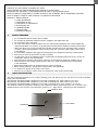
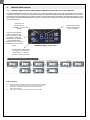
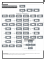
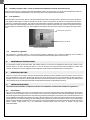
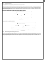
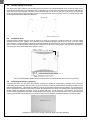
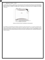
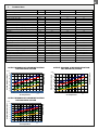
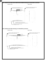
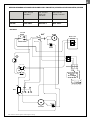
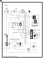
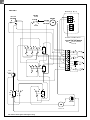
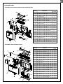
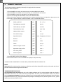
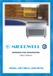
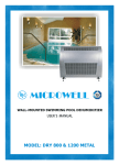
WALL-MOUNTED SWIMMING POOL DEHUMIDIFIER
USER´S & INSTALLATION MANUAL
MODEL: DRY 300 METAL/SILVER
DRY 400 METAL/SILVER
DRY 500 METAL/SILVER
2
Thank you for your decision to purchase our device.
Please read this user manual carefully before starting to use the device.
Please keep the instructions of this practical quide in order to get a quick know-how.
We do not take any responsibility or provide warranty in case of damage, loss or damnification caused by
incorrect usage or usage for other purposes, not specified in this manual.
Contents: 1. Safety measures
2. Usage specification
3. Instructions for use
4. Instructions for maintenance
5. Servicing the unit
6. Installation guide
7. Technical data
8. Warranty conditions
1.
SAFETY MEASURES
·
·
·
·
·
·
·
·
·
·
·
·
·
2.
Do not manipulate with the device with wet hands.
Do not spray any flammable substances into the equipment; this might lead to fire.
Do not clean the device with water.
The cover of the device is made of rustless steel. For cleaning and polishing the cover without making any
undesired matt blobs on its surface, use grooming and protective articles suitable for rustless metal surfaces.
Apply some drops on a dry and non-fluffy clout and then smoothly wipe it into the surface. After 2 minutes
of drying, wipe it again and polish it using a dry and clean clout (grooming article together with a clout is
in the package).
Do not clean the equipment with aggressive cleaning agents, this might lead to damage or deformations.
Never throw or insert any objects into any tube or opening.
Use this device only for the intended purpose, as described in the attached instructions for use. Do not use
components, which are not recommended.
Never block the air opening of the product. Protect the air openings from clogging by particles, hair etc.
When the device is not running correctly (smoke, smell, etc.), switch off the device by a circuit breaker
in the switchboard.
Repairs and relocations must be performed only by a service technician.
Before cleaning the device, switch off the circuit breaker in the switchboard.
Do not place any objects on the surface of the device.
When you do not intend to use the device for a longer time, switch off the circuit breaker.
USAGE SPECIFICATION
The units are designed especially for use in indoor swimming pools, spas and saunas. They can also be very useful in laundries,
drying rooms and elsewhere.
Microwell DRY 300 METAL/SILVER is designed for rooms with a swimming pool, which surface is up to 30 m².
Microwell DRY 400 METAL/SILVER is designed for rooms with a swimming pool, which surface is up to 45 m².
Microwell DRY 500 METAL/SILVER is designed for rooms with a swimming pool, which surface is up to 60 m².
The condition of using the equipment is keeping a room temperature within a range between min. 22 ° C and max. 35 C ° .
Optimal situation occurs when the room temperature is about 2-3 C ° higher than a swimming pool water-temparature.
EXHAUST GRID
UNIT COVER
HYGROSTAT
INTAKE GRID
WALL-MOUNTED SWIMMING POOL DEHUMIDIFIER - OWNER´S & INSTALLATION MANUAL
3
3.
INSTRUCTIONS FOR USE
3.1.
Humidity regulation with an inbuilt digital humidistat located in the cover of the equipment
The inbuilt humidistat is located in the cover of the device. It reads the humidiy of the incoming air, and depending on the set value,
switches on the compressor. In indoor swimming pool halls, the optimal air humidity level should range between 55% and 65 %.
Decreasing the level of humidity under the above mentioned range is not desirable, considerating the physiological aspects as well
as the aspects of providing building protection. Moreover, it increases the consumption of electrical energy. The humidistat can be
controlled by the user.
Luminous point
signals, that the
humidity is shown on
display.
Luminous point indicates
that the regulator gives
signal to heat the air. This is
applicable if LPHW and
Solenoid valve are installed.
Not illuminated point
indicates that the requested
air temperature is lower than
actual.
Luminous point signals,
that the temperature is
shown on display.
Humidistat display (front view)
Luminous point indicates that
the regulator gives signal to
dehumidify, i.e. requested
humidity is lower than actual.
Failure reporting
Er1
0-E
S-E
Memory failure. Switch off and then switch on again the electrical connection.
If the failure reporting continues, please ask us to change the component.
Sensor failure. The electrical connection of the sensor is broken off.
Please control the cable.
Sensor failure. The sensor is short-circuited. Please control the cable.
WALL-MOUNTED SWIMMING POOL DEHUMIDIFIER - OWNER´S & INSTALLATION MANUAL
4
By keeping the “set” button pressed for longer than 5 secs, the setting gets finished and you return to a mode of current
humidity display.
In case of inactiveness for longer than 30 secs, this is done automatically.
WALL-MOUNTED SWIMMING POOL DEHUMIDIFIER - OWNER´S & INSTALLATION MANUAL
5
3.2.
Humidity regulation with a back-up mechanical humidistat located in the electronic box
In the electronic box there is a back-up mechanical humidistat, which is set on the value of 70 % RH. This humidistat has a back-up
function in case of digital humidistat failure. User should not perform any regulation of this humidistat.
3.3.
Fan regulation
Under the inside cover of the unit, there is a two-positional fan mode switch. In the first position, the fan runs even if the compressor
of the appliance has stopped: continuous operation of the fan. In the second position, the fan only runs simultaneously with the
compressor: periodical duty of the fan. The continuous operation mode of the fan is preferable, since the humidity reader built in the
device continuously reads humidity, and therefore a greater accuracy is reached. At the same time, continuous operation of the fan
results in better air circulation in the room. The installation work supplier selects the mode of the fan according to the request of the
user.
Continuous duty of the fan
Periodical duty of the fan
Switch of fan operation
3.4.
Compressor regulation
The compressor´s operation starting is for securing its protection, delayed by min. 3 minutes. Depending on the humidity of
environment, it may last even longer. The user must not manipulate with the setting element of a time relay.
4.
MAINTENANCE INSTRUCTIONS
It is necessary to make sure that the intake- and exhaust outlet are not covered. It is forbidden to place towels or clothes on the
exhaust outlet, to dry them. Cleaning the device´s cover can be done only using grooming articles suitable for rustless steel
surfaces. In case there is a water dripping from the equipment, check whether a condensate pipe is not obstructed.
5.
SERVICING THE UNIT
At least once a year, it is necessary to have the unit checked and cleaned by a service specialist. This is necessary in order to secure a
long operational life of the device. Cleaning the interior parts of the device by a user is not recommended, as this may lead to a
damage on the unit. The device contains mobile elements as well as elements under electrical pressure, therefore the interior parts
can be cleaned only by a certified electrician with an appropriate knowlegde of refrigerating technology.
6.
INSTALLATION GUIDE
The unit must be installed in compliance with the local installation and electrical installation regulations !
6.1.
Unit location
The unit is to be installed on the wall or on the mobile stand. To ensure the right operations of the dehumidifier and its maximum
efficiency in terms of humidity control, it is necessary to ensure proper air circulation into and from the dehumidifier. This requires
the actual unit placement appropriately into the swimming pool hall respecting basic prerequisites of air circulation and air flow. It is
strictly forbidden to install the unit just below the ceiling. At least 200mm of a free space must be kept above the unit and at least
150mm below the unit. Each swimming pool hall is individual thus a special care needs to be taken to choose a proper dehumidifier
placement. It is forbidden to install the unit on the ground. It is also strictly forbidden to block the air inlet and outlet with any objects
(canoe, buckets, ceiling beams, etc.). For maintenance purposes please keep free space of 200mm on both sides
of the dehumidifier.
WALL-MOUNTED SWIMMING POOL DEHUMIDIFIER - OWNER´S & INSTALLATION MANUAL
6
6.2.
Equipment fixation
The equipment has a self-supporting construction and is very easy to install.
There is an installation bracket included in the equipment accessories, which must be fixed on the wall. The axis of the fixation slots
is 210 mm lower than the top edge of the device. The distance between the fixation slots is 420 mm (DRY 300 METAL/SILVER and
DRY 400 METAL/SILVER) and 360 mm (DRY 500 METAL/SILVER). When the bracket is fixed, it is possible to hang up the device
without dismounting its cover.
Model DRY 300 METAL/SILVER and DRY 400 METAL/SILVER
TOP EDGE OF THE DEVICE
SPIRIT LEVEL
BRACKET
FIXATION SLOTS
Model DRY 500 METAL/SILVER
TOP EDGE OF THE DEVICE
SPIRIT LEVEL
BRACKET
FIXATION SLOTS
6.3.
Dismounting and mounting of the cover
The cover can be dismounted after releasing two screws (DRY 300 METAL/SILVER and DRY 400 METAL/SILVER) or three screws
(DRY 500 METAL/SILVER) at the bottom of the device. Release the screws, pull the bottom part of the cover toward yourself and
then, by lifting it shortly, rake down the cover from the rear plate. To mount the cover, carry the procedure out in reverse order.
WALL-MOUNTED SWIMMING POOL DEHUMIDIFIER - OWNER´S & INSTALLATION MANUAL
7
6.4.
Position assuring of the device
The design of the device enables its safe mounting and proper fixation even if lifted accidentally. There are slots for safety screws
accessible after dismounting a front fibreglass cover, located in the top corners of the rear plate. There is an arrow that indicates
safety screw slots in the rear plate. The safety screw is fixed through a slot in the rear plate into a wall fastener. It prevents the
device from being pulled out and from falling out from a mounting bracket. At the same time, it secures a vertical position of the
device together with a device alignment with a wall.
REAR PLATE
SAFETY SCREW SLOTS
6.5.
Condensate drain
Condensed water is drained from the device by the force of gravity. It is necessary to locate the device in a way that enables
sufficient condensed water gradient. The condensate must be delivered through a siphon into the sewer or into the outside
environmemt. It is strictly forbidden to deliver the condensate back into the swimming pool, as it may be bacterially contaminated.
There is a tube for condensed water delivery located at the bottom of the device, on the left side. This tube must be pluged into
a sewerage pipe with an internal diameter of minimum 18 mm.
50
117
THREAD G ½ '’ MALE
LOCATION OF CONNECTION- FROM BACK SIDE
15
44
50 100
CONDENSATE DRAINAGE (FROM THE REAR)
PIPING WITH MINIMUM INTERNAL DIAMETER OF 18 mm
POWER SUPPLY (FROM THE REAR)
CYSY WIRE 3C x 1.5 (3C x 2.5) mm2
DRY 300 METAL/SILVER, DRY400 METAL/SILVER and DRY 500 METAL/SILVER with connections (front view)
6.6
Connecting the device to the mains
Connecting the device onto the mains and protection securing must satisfy the requirements of relevant norms. Connection
requirements are the following: 220-240 V/50Hz, protection 10A (DRY 300 METAL/SILVER and DRY 400 METAL/SILVER) and 16A
(DRY 500 METAL/SILVER) with a mains-fuse that has a current-carrying differential disconnecting capacity, not exceeding 30mA.
There is a terminal for connection to the mains, located on the left hand side of the device. The master switch of the device must be
located outside the swimming pool area, it must be bipolar and with L and N conductors´ disconnecting. The device for
disconnecting the appliance from the mains must be inbuilt to a steady point. There has to be a distance of min. 3 mm between the
contacts (when switched off) for all the poles. Connection of the device to the mains must be performed by a certified electrician.
Preparation of electric power supply, condensate drain and console mounting
WALL-MOUNTED SWIMMING POOL DEHUMIDIFIER - OWNER´S & INSTALLATION MANUAL
8
DEVICE LOCATION
Device location must be in accordance with HD 384.7.702 S1 and IEC 60364-7-702 standard.
It is recommended to locate the device outside zones 0,1 and 2.
In case the device is located into zones 2 or 1, HD and IEC standards´requirements must be satisfied.
ZONE 1, IPX4
Swimming pools which are not
cleaned by splashing water
In the distance of 1250 - 2000 mm from the swimming pool edge
in accordance with HD and IEC standards
and at least 300 mm above the floor
ZONE 2, IPX2
OUTSIDE THE ZONES
Swimming pools which
are not cleaned by
splashing water
In the distance of 2000 - 3500
mm from the swimming pool
edge. In accordance with HD and
IEC standards and at least 300
mm above the floor, in order to
secure the sufficient aircirculation. It is strictly forbidden
to install the device onto the floor.
At least 1250 mm (i.e. out of the reach of the hand)
from the side edge of the shower cabinet. It cannot
be placed above the shower cabinet.
SWIMMING POOL
In the distance of 1250 mm or less
from the swimming pool edge, the
bottom edge of the device must be
2500 mm above the swimming
pool surface.
At least 1250 mm (i.e. out of the reach of the hand) from
the side edge of the wash basin, in the minimum height of
1200 mm above ground. It cannot be placed above the
wash basin.
OUTSIDE THE ZONES
OUTSIDE THE ZONES
In the distance of at least 1500 mm
from the vertical plane around jumping
platforms, jumping boards and starting
blocks, 2500 mm above the highest
surface, where people are likely to stay.
If the unit is in the distance of less or
equal to 1250 mm horizontally from
the edge of the swimming pool, then
it must be raised up to the height of
2500 mm from the swimming pool
surface; if the pool is embedded
under the floor, then the unit must be
raised up to the height of 2500 mm
from the floor.
SWIMMING POOL
It is inevitable to locate the device outside the zones, where cleaning with splashing water is supposed. Connection of the unit to
the mains and its protection must correspond with the applicable standards. Electrical supply of the unit must be carried out by a
protective isolating transformer, or it must be protected by a current protector with a current-carrying differential disconnecting
capacity, not exceeding 30mA.
WALL-MOUNTED SWIMMING POOL DEHUMIDIFIER - OWNER´S & INSTALLATION MANUAL
9
6.7.
LPHW heater element - to order
The LPHW heater elements are supplied only to order. Connection of the hot water heater element onto the LPHW plumbing is
carried out similarly to the installation of radiators. On the feeder pipe, it is connected by a control valve and on the return pipe by a
closing screw joint. The LPHW is not supplied with a control valve and a screw joint; these are supplied by the supplier
of the heating.
50
117
THREAD G ½ '’ MALE
LOCATION OF CONNECTION- FROM BACK SIDE
15
44
50 100
CONDENSATE DRAINAGE (FROM THE REAR)
PIPING WITH MINIMUM INTERNAL DIAMETER OF 18 mm
POWER SUPPLY (FROM THE REAR)
2
CYSY WIRE 3C x 1.5 (3C x 2.5) mm
Attachment of the heater element to the distribution of the heating water
After installing the LPHW plumbing and leading the LPHW into the element under pressure, it is necessary to bleed the heater
element. The bleeding valve is located on the feeder pipe of the LPHW heater element. To secure that the LPHW heater element
works always at full heat output, blowing onto the unit by a fan must be provided even when no dehumidification is being
performed. Therefore, when using the LPHW heater element, the switch of fan operation must be switched into the position of
continuous operation.
WALL-MOUNTED SWIMMING POOL DEHUMIDIFIER - OWNER´S & INSTALLATION MANUAL
10
7.
Technical data
TECHNICAL DATA
UNITS
DRY 300 METAL/SILVER
m2
For swimming pools with max. surface
DRY 400 METAL/SILVER
DRY 500 METAL/SILVER
45
60
66
30
DEHUMIDIFICATION PERFORMANCE:
at 30 °C and 60 % RH
l/24 h
33
48
at 30 °C and 70 % RH
l/24 h
42
53
83
at 30 °C and 80 % RH
Operational temperature (standard)
Operational temperature (antifreeze stat)
l/24 h
47
58
101
Operational temperature (expansive valve)
Operational temperature (hot gas defrost)
Operating humidity range
Air flow
Noisiness (in 1 m distance)
Thermal capacity
Electrical power consumption
°C
22-35
22-42
22-35
°C
15-35
15-35
15-35
°C
22-42
22-42
22-42
°C
5-35
5-35
5-35
% RH
20-100
20-100
20-100
m /h
3
440
550
740
dB (A)
42
42
44
W
1900
1900
3500
W
700
700
1000
V/Hz/f
230/50/1
230/50/1
230/50/1
Operating current / Starting current
A
4.4 / 15.8
4.4 / 15.8
7.5 / 30
Protection
A
10
10
16
Mechanical Protection
IP
44
44
44
Conductor
mm2
CYSY 3C x 1.5
CYSY 3C x 1.5
CYSY 3C x 2.5
Pipe for condensate delivery (min. interior diameter)
Sizing (width x height x depth)
Package sizing (width x height x depth)
mm
d 18
d 18
d 18
mm
780 x 653 x 300
780 x 653 x 300
1245 x 653 x 300
mm
850 x 735 x 345
850 x 735 x 345
1315 x 735 x 345
Weight - net / in package
kg
50/56
50/56
Refrigerant - R 410 A
kg
0.5
0.5
Max. pressures in the system HP/LP
bar
28.5/8.5
28.5/8.5
28.5/8.5
Dehumidifier efficiency rate
DER
2.4
2.4
2.7
Voltage
77/86
0.75
* Measured in acoustic chamber (background noise filtered off).
80%
50
70%
40
60%
30
50%
40%
20
10
0
Dehumidification output
(l/24h)
120
Relative humidity
Dehumidification output
(l/24h)
60
OUTPUT DIAGRAM OF DEHUMIDIFICATION
DRY 500 METAL/SILVER
80%
100
70%
60%
80
50%
60
40%
Relative humidity
OUTPUT DIAGRAM OF DEHUMIDIFICATION
DRY 300 METAL/SILVER
40
20
0
15
20
25
30
35
15
(°C)
Air temperature
20
25
Air temperature
30
35
(°C)
OUTPUT DIAGRAM OF DEHUMIDIFICATION
DRY 400 METAL/SILVER
70
80%
60
70%
60%
50
50%
40
40%
30
Relative humidity
Dehumidification output
(l/24h)
80
20
10
0
15
20
25
Air temperature
30
35
(°C)
WALL-MOUNTED SWIMMING POOL DEHUMIDIFIER - OWNER´S & INSTALLATION MANUAL
11
DRY 300 METAL/SILVER and DRY 400 METAL/SILVER swimming pool dehumidifier parameters
SIDE VIEW
FRONT VIEW
SLIPPING OUT FROM A CONSOLE PREVENTING
POSITION SECURING (FROM BEHIND)
SLIPPING OUT FROM A CONSOLE PREVENTING
POSITION SECURING (FROM BEHIND)
CONSOLE
CONDENSATE DRAIN (FROM THE BEHIND)
PIPE WITH AN INTERNAL DIAMETER OF MINIMUM 18 mm
POWER SUPPLY (FROM THE BEHIND)
2
CYSY WIRE 3C x 1.5 mm
DRY 500 METAL/SILVER swimming pool dehumidifier parameters
FRONT VIEW
SIDE VIEW
SLIPPING OUT FROM A CONSOLE PREVENTING
POSITION SECURING (FROM BEHIND)
SLIPPING OUT FROM A CONSOLE PREVENTING
POSITION SECURING (FROM BEHIND)
CONSOLE
CONDENSATE DRAIN (FROM THE BEHIND)
PIPE WITH AN INTERNAL DIAMETER OF MINIMUM 18 mm
POWER SUPPLY (FROM THE BEHIND)
CYSY WIRE 3C x 2,5 mm2.
WALL-MOUNTED SWIMMING POOL DEHUMIDIFIER - OWNER´S & INSTALLATION MANUAL
12
WIRING DIAGRAM OF MODEL MICROWELL DRY 300 METAL/SILVER and DRY 400 METAL/SILVER
DRY 300/400
Standard
DRY 300/400
EASY 200 /
HYG 6001
DRY 300/400
LPHW / Solenoid
METAL
DRY 300.1
DRY 300.1
DRY 300.2
SILVER
DRY 300.1
DRY 300.1
DRY 300.2
DRY 300.1
Note: Producer reserves right to make changes on wiring.
WALL-MOUNTED SWIMMING POOL DEHUMIDIFIER - OWNER´S & INSTALLATION MANUAL
13
DRY 300.2
Note: Producer reserves right to make changes on wiring.
WALL-MOUNTED SWIMMING POOL DEHUMIDIFIER - OWNER´S & INSTALLATION MANUAL
14
WIRING DIAGRAM OF MODEL MICROWELL DRY 500 METAL/SILVER
DRY 500 Standard
DRY 500
EASY 200 /
HYG 6001
DRY 500 LPHW /
Solenoid
METAL
DRY 500.1
DRY 500.1
DRY 500.2
SILVER
DRY 500.1
DRY 500.1
DRY 500.2
DRY 500.1
Note: Producer reserves right to make changes on wiring.
WALL-MOUNTED SWIMMING POOL DEHUMIDIFIER - OWNER´S & INSTALLATION MANUAL
15
DRY 500.2
Note: Producer reserves right to make changes on wiring.
WALL-MOUNTED SWIMMING POOL DEHUMIDIFIER - OWNER´S & INSTALLATION MANUAL
16
EXPANDED VIEW
MICROWELL DRY 300 METAL/SILVER and DRY 400 METAL/SILVER
Position
1
1,1
1,2
2
3
4
5
6
7
8
9
10
11
12
13
14
15
16
17
18
19
20
21
24
25
26
Number
of pieces
Metal / Stainless stell cover
1
Digital humidistat FOX-2SH
1
Humidity sensor DS-SH104
1
Back metal sheet
1
Ventilator metal sheet
1
Metal sheet in front of the exchanger
1
Metal sheet above the exchanger
1
Metal sheet under the compressor
1
Electro-box metal sheet
1
Compressor cover
1
Evaporator tray
1
Compressor tray
1
Exchanger 400 - evaporator
1
Exchanger 650 - condenser
1
Ventilator EBM D4-E133-DL01-D6
1
Compressor DAIKING YZG-E24RAY2
1
Low pressure valve Ranco HR00001 A5R703 1
Filter 20g d4/6mm
1
Filling valve, pipe d6, thread SAE 1/4"
2
Sunction pipe d10mm
1
Pressure pipe d6mm
1
Screw ST4.8 x 38
2
Screw 3.5 x 13
9
Rubber grommet d15 DA 110/150/10
4
Rubber grommet d30 DA 230/300/20
4
Condensate pipe d18x3, 1m
1
Component
MICROWELL DRY 500 METAL/SILVER
Position
1
1,1
1,2
2
3
4
5
6
7
8
9
10
11
12
13
14
15
16
17
18
19
20
21
22
25
26
27
Component
Metal / Stainless steel cover
Digital humidistat FOX-2SH
Humidity sensor DS-SH104
Back metal sheet
Metal sheet in front of the exchanger
Metal sheet above the exchanger
Metal sheet under the compressor
Ventilator metal sheet
Electro-box metal sheet
Holding metal sheet for ventilator
Compressor cover
Evaporator tray
Compressor tray
Exchanger 720 - evaporator
Exchanger 1115 - condenser
Ventilator EBM K4E146-AB73-21
Compressor DAIKING YZG-E35RY2
Low pressure valve Ranco HR00001 A5R704
Filter 30g d6/6mm
Filling valve, pipe d6, thread SAE 1/4"
Sunction pipe d10mm
Pressure pipe d6mm
Screw ST3.5 x 13
Screw ST4.8 x 38
Rubber grommet d30 DA 230/300/20
Rubber grommet d15 DA 11d180/10
Condensate pipe d18x3, 1m
Number of
pieces
1
1
1
1
1
1
1
1
1
1
1
1
1
1
1
1
1
1
1
2
1
1
9
3
7
4
1
WALL-MOUNTED SWIMMING POOL DEHUMIDIFIER - OWNER´S & INSTALLATION MANUAL
17
8.
WARRANTY CONDITIONS
The following exceptions stated by Microwell, Ltd. apply within the warranty.
No claims will be accepted if:
1. The dehumidifier is used in an incorrect way, not as described in this manual.
2. The dehumidifier is installed in an incorrect way, not as described in this manual.
3. The dehumidifier was put to operation by an unauthorized person.
4. The air flow through the dehumidifier is out of the defined borders.
5. The unit has been exposed to a mechanical force causting scratches, blends, compressions, pipe rupture, etc.
6. The water´s pH level and/or chemical condition is out of the defined borders:
Acidity / pH level:
pH
7,4 +/- 0,4
Total alkalinity, as CaCO3
ppm
80-120
Total hardness, as CaCo3
ppm
100-300
Total melted dry mass
ppm
max. 3000
Maximal saline content
wt/wt
6%
Free chlorine range
ppm
1,0-3,0
Superchlorination
ppm
Bromine
ppm
2-3
Baquacil
ppm
25-50
Ozone
ppm
0,8-1,0
Maximum copper content
ppm
max. 2
Aquamatic single purifier
ppm
max. 2
Tarn clean purifier
ppm
max. 2
Sherwood purifier
ppm
max. 2
max. 30 ppm/max. 24 hours
7. The dehumidifier suffered frost damage.
8. The electric tension source is insufficient or improper in any other way.
IN CASE OF ANY UNCERTAINTY YOU MAY HAVE, PLEASE FEEL FREE TO CONTACT US !
NOTE:
When applying for warranty, please contact your distributor and indicate dehumidifier model, serial number and date of
purchase. Please describe the genesis of the failure.
TRANSPORT INSTRUCTIONS:
The dehumidifiers must be transported only in the original packaging and in a vertical position. Make sure that the
dehumidifier cannot turn over or fall down during transportation. Do never put the dehumidifier aside! It may lead to
serious compressor damage! No claims are accepted in case of any damage caused by transportation. When receiving
the product delivered to you, please check whether the package is not damaged. If any kind of objections occurs, please
make a proper documentation of them.
WALL-MOUNTED SWIMMING POOL DEHUMIDIFIER - OWNER´S & INSTALLATION MANUAL
MICROWELL, Ltd.
Distributed by:
SNP 2018/42
927 01 Šaľa, Slovakia
Phone: +421 31 7020 540-1
Fax: +421 31 7020 542
E-mail: [email protected]
www.microwell.eu
Version: 2014/04/09