1
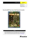
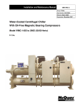
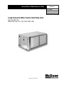
Installation & Maintenance Data
IM 526-17
Group: WSHP
Part Number: 106581303
Date: June 2006
Large Horizontal Water Source Heat Pump Units
Size 070, 090, 120
Model CDD, CDE, CDL, CDS, CME, CMG, CMS
®
©2006 McQuay International
Contents
Unit Operation . . . . . . . . . . . . . . . . . . . . . . . . . . . . . 13-15
Sequence of Operation . . . . . . . . . . . . . . . . . . . . . . . . . 14
Thermostat Connections . . . . . . . . . . . . . . . . . . . . . 16-17
Motorized Valve & Relay . . . . . . . . . . . . . . . . . . . . . . . . 18
Pump Restart Relay. . . . . . . . . . . . . . . . . . . . . . . . . . . . 19
Boilerless System Kit. . . . . . . . . . . . . . . . . . . . . . . . . . . 20
Field Installed Options on MicroTech Units . . . . . . . . . . 21
Troubleshooting WSHP . . . . . . . . . . . . . . . . . . . . . . . . . 22
Maintenance . . . . . . . . . . . . . . . . . . . . . . . . . . . . . . . . . 23
Model Nomenclature . . . . . . . . . . . . . . . . . . . . . . . . . . . . 2
Transportation & Storage . . . . . . . . . . . . . . . . . . . . . . . . . 3
Installation . . . . . . . . . . . . . . . . . . . . . . . . . . . . . . . . . . 3-6
Electrical Data . . . . . . . . . . . . . . . . . . . . . . . . . . . . . . . . . 7
Piping . . . . . . . . . . . . . . . . . . . . . . . . . . . . . . . . . . . . . . . 7
Cleaning & Flushing System . . . . . . . . . . . . . . . . . . . . . 8-9
Start-up. . . . . . . . . . . . . . . . . . . . . . . . . . . . . . . . . . . . . . 9
Operating Limits . . . . . . . . . . . . . . . . . . . . . . . . . . . . . . 10
Typical Wiring Diagrams . . . . . . . . . . . . . . . . . . . . . . 11-12
Model Nomenclature
W
CDD
1
009
D
Z
Product Catagory
W = WSHP
Coil Options
None
Product Identifier
See box below
Voltage
F = 208/23-60-3
K = 460-60-3
L = 575-60-3
N = 380-50-3
Design Series
1 = A Design
2 = B Design
3 = C Design
4 = D Design
5 = E Design
Nominal Capacity
070 = 70,000
090 = 90,000
120 = 120,000
McQuay Product Identifiers
CDD = Ceiling Mtd./DDC Control/Ext. Range/Less Board
CDE = Ceiling Mtd./DDC Control/Ext. Range
CDL = Ceiling Mtd./DDC Control/Std. Range/Less Board
CDS = Ceiling Mtd./DDC Control/Std. Range
CME = Ceiling Mtd./Mark IV/Ext. Range
CMG = Ceiling Mtd./Mark IV/Geothermal
CMS = Ceiling Mtd./Mark IV/Std. Range
Note: Installation and maintenance are to be performed only by qualified personnel who are familiar with local codes
and regulations, and are experienced with this type of equipment. Caution: Sharp edges are a potential injury hazard.
Avoid contact with them.
Page 2 / IM 526
Transportation & Storage
Upon receipt of the equipment, check carton for visible
damage. Make a notation on the shipper’s delivery ticket
before signing. If there is any evidence of rough handling,
immediately open the cartons to check for concealed damage. If any damage is found, notify the carrier within 48
hours to establish your claim and request their inspection
and a report. The Warranty Claims Department should then
be contacted.
Do not stand or transport the machines on end. For storing, each carton is marked with “up” arrows.
In the event that elevator transfer makes up-ended positioning unavoidable, absolutely ensure that the machine is
in the normal upright position for at least 24 hours before
operating.
Temporary storage at the job site must be indoors, completely sheltered from rain, snow, etc. High or low temperatures naturally associated with weather patterns will not
harm the conditioners. Excessively high temperatures,
140°F (60°C) and higher, may deteriorate certain plastic
materials and cause permanent damage.
Installation
General
1. To prevent damage, this equipment should not be
operated for supplementary heating and cooling during
the construction period.
7. The installing contractor will find it beneficial to confer
with piping, sheet metal, ceiling and electrical foremen
before installing any conditioners.
2. Inspect the carton for any specific tagging numbers
indicated by the factory per a request from the
installing contractor. At this time the voltage, phase
and capacity should be checked against the plans.
NOTE: Check the unit name plate for correct voltage with
the plans before installing the equipment. Also,
make sure all electrical ground connections are
made in accordance with local code.
3. Check the unit size against the plans to ensure unit
installation is in the correct location.
4. After removing the carton, remove the hanger kit from
the fan housing.
5. Before installation, check the available ceiling height
versus the height of the unit.
8. Remove all shipping blocks in the fan wheel.
9. We recommend that the contractor cover the conditioners with plastic film to protect the machines during
finishing of the building. This is critical while spraying
fireproofing material on bar joists, sandblasting, spray
painting and plastering.
6. Note the location and routing of water piping, condensate drain piping, and electrical wiring. The locations of
these items are clearly marked on submittal drawings.
IM 526 / Page 3
Unit Location
1. Locate the unit in an area that allows for easy removal of
the filter and access panels. Leave enough space for
service personnel to perform maintenance or repair.
Provide sufficient room to make water, electrical and
duct connections.
2. The contractor should make sure that adequate ceiling
panel access exists, including clearance for hanger
brackets, duct collars and fittings at water and electrical
connections.
3. Allow adequate room below the unit for a condensate
trap and do not locate the unit above pipes.
5. Each unit is furnished with a hanger kit. The kit is
shipped unassembled and includes hanger brackets,
rubber isolators, washers, bolts and lock washers. Lay
out the threaded rods per the dimensions in Figure 1.
Assemble the hangers to the unit as shown in Figure 2.
Securely tighten the brackets to the unit.
6. When attaching the hanger rods to the unit, a double nut
is recommended since vibration could loosen a single
nut. The installer is responsible for providing the hex nuts
when installing hanger rods.
7. Leave minimum 3" (76 mm) extra threaded rod below the
double nuts or minimum 3" (76 mm) clearance between
top of unit and ceiling above to facilitate top panel
removal for servicing
4. Each unit is suspended from the ceiling by four threaded
rods. The rods are attached to the unit corners by a hanger bracket through a rubber isolator. Caution: Do not use
rods smaller than specified below. The rods must be
securely anchored to the ceiling or to the bar joists.
8. The unit should be pitched towards the drain in both
directions to facilitate condensate removal.
Figure 1. Hanger bracket detail, sizes 070 thru 120
Figure 2. Unit sizes 070 thru 120
2"
(51 mm)
42"
(1067
mm)
Fan
Assembly
Comp
Comp
44"
(1118
mm)
Control
Box
Airflow
By McQuay
International
Coil
80" (2032 mm)
82" (2083 mm)
Page 4 / IM 526
2"
(51 mm)
By Others
5/8” Threaded Rod (By Others)
Air Balancing
Unit sizes 070 thru 120 are supplied with a variable pitch
motor sheave to aid in airflow adjustment. They are set at
the factory according to Table 1 shown below.
When the final adjustments are complete, the current
draw of the motors should be checked and compared to
the full load current rating of the motors. The amperage
must not exceed the service factor stamped on the motor
nameplate.
Upon completion of the air balance, it is a common
industry recommendation that the variable pitched motor
sheave be replaced with a properly sized fixed sheave. A
matching fixed sheave will provide longer belt and bearing
life and vibration free operation. Initially, it is best to have a
variable pitched motor sheave for the purpose of air balancing, but once the balance has been achieved, fixed
sheaves maintain balancing and alignment more effectively.
Adjustment (See Figure 3)
1. All sheaves should be mounted on the motor or driving
shaft with the setscrew “A” toward the motor
2. Be sure both driving and driven sheaves are in alignment
and that shafts are parallel.
3. Fit internal key “D” between sheave and shaft, and lock
setscrew “A” securely in place.
Adjusting
1. Loosen setscrews “B” and “C” in moving parts of sheave
and pull out external key “E”. (This key projects a small
amount to provide a grip for removing.)
Figure 3.
2. Adjust sheave pitch diameter for desired speed by opening moving parts by half or full turns from closed position. Do not open more than five full turns.
3. Replace external key “E” and securely tighten setscrews
“B” over key and setscrews “C” into keyway in fixed half
of the sheave.
4. Put on belts and adjust belt tension to 4 lbs. – 0.7 lbs.
(18N – 3N) for a 1⁄2" to 3⁄4" (13 mm to 19 mm) belt deflection height.
5. To determine the deflection distance from normal position, use a straightedge or stretch a cord from sheave to
sheave to use as a reference line. On multiple-belt drives
an adjacent undeflected belt can be used as a reference.
6. Future adjustments should be made by loosening the
belt tension and increasing or decreasing the pitch diameter of the sheave by half or full turns as required.
Readjust belt tension before starting drive.
7. Be sure that all keys are in place and that all setscrews
are tight before starting drive. Check setscrews and belt
tension after 24 hours service.
8. When new V-belts are installed on a drive, the initial tension will drop rapidly during the first few hours. Check
tension frequently during the first 24 hours of operation.
Subsequent retensioning should fall between the minimum and maximum force.
Figure 4. Drive belt adjustment
A
Span Le
ngth (t)
B
Deflec
tio
Force n
E
D
h
Key E projects to
provide a grip for
removing.
d
D
h=
C
t=
Single Groove
Table 1. 60 Hz
Unit
Size
070
090
120
Motor
HP
11⁄2
3
11⁄2
3
3
5
C
t
64
C2 –
( )
D-d
2
Where: t = Span length, inches (mm)
C = Center distance, inches (mm)
D = Larger sheave diameter, inches (mm)
d = Smaller sheave diameter, inches (m)
h = Deflection height, inches (mm)
Note: The ratio of deflection to belt span is 1:64.
Table 1B. 50 Hz
RPM
Range
756 – 902
907 –1081
698 – 832
907 –1081
756 – 901
907 –1081
Factory
Setting (RPM)
785
904
858
904
814
904
Motor Sheave
Position
4 Turns Open
5 Turns Open
11⁄2 Turns Open
5 Turns Open
3 Turns Open
5 Turns Open
Unit
Size
070
090
120
Motor
HP
11⁄2
11⁄2
3
RPM
Range
756 – 901
720 – 860
756 – 902
Factory
Motor Sheave
Setting (RPM)
Position
786
4 Turns Open
858
11⁄2 Turns Open
815
3 Turns Open
Filter Access
Each unit is shipped with a filter bracket for side filter
removal. For bottom removal push the filter up into top
bracket to gain clearance of bottom bracket and remove
the filter. Also, a sheet metal duct filter retainer can be fabricated when return air duct work is used.
IM 526 / Page 5
Ductwork & Attenuation
Discharge ductwork is normally used with these conditioners. Return air ductwork may also be required.
All ductwork should conform to industry standards of
good practice as described in the ASHRAE Systems Guide.
The discharge duct system will normally consist of a
flexible connector at the unit, a transition piece to the full
duct size, a short run of duct, an elbow without vanes, and
a trunk duct teeing into a branch duct with discharge diffusers as shown in Figure 5. The transition piece must not
have angles totaling more than 30° or severe loss of air performance can result. Do not connect the full duct size to the
unit without using a transition piece down to the size of the
discharge collar on the unit. With metal duct material, the
sides only of the elbow and entire branch duct should be
internally lined with acoustic fibrous insulation for sound
attenuation. Glass fiber duct board material is more absorbing and may permit omission of the canvas connector.
The ductwork should be laid out so that there is no line
of sight between the conditioner discharge and the
distribution diffusers.
Return air ducts can be brought in through a low side
wall filter-grille and then up through the stud pieces to a
ceiling plenum or through air ceiling filter-grilles. The ceiling
filter-grille must not be placed directly under the
conditioner.
Return air ductwork can be connected to the standard
filter rack. See Figure 6 (side filter removal shown). The filter rack can be installed for bottom filter removal or side filter removal by locating the brackets. For side filter removal
the brackets should be located on the bottom, left side, and
top. For bottom filter removal the brackets should be
mounted on the left side top and right side with the spring
clips supporting the filter.
Do not use sheet metal screws directly into the unit cabinet for connection of supply or return air ductwork, especially return air ductwork which can hit the drain pan or the
air coil.
Figure 5.
Figure 6. Filter rack/return air duct collar
Both Sides Internally Lined With
Acoustic Fibrous Glass Insulation
Transformation
Piece
Square Elbow
Trunk Duct
Discharge Collar
On Heat Pump
Canvas
Collar
Branch Duct
Internally Lined
With Acoustic
Fibrous
Insulation
Heat
Pump
Suggested Duct Layout For
Multiple Diffuser Application
Standard 2" (51 mm)
for sizes 070 thru 120
2x2 Ft.
Diffuser
(Example
Only)
Ventilation Air
Ventilation may require outside air. The temperature of the
ventilation air must be controlled so that mixture of outside
air and return air entering the conditioner does not exceed
conditioner application limits. It is also typical to close off
the ventilation air system during unoccupied periods (night
setback).
The ventilation air system is generally a separate build-
Page 6 / IM 526
ing subsystem with distribution ductwork. Simple introduction of the outside air into each return air plenum chamber
reasonably close to the conditioner air inlet is not only adequate, but recommended. Do not duct outside air directly to
the conditioner inlet. Provide sufficient distance for thorough mixing of outside and return air. See Operating Limits
on page 10.
Electrical Data
General
1. Verify the compatibility between the voltage and phase
of the available power and that shown on the unit serial
plate. Line and low voltage wiring must comply with local
codes or the National Electrical Code, whichever
applies.
2. Apply correct line voltage to the unit. A 7⁄8" (22mm) hole
and/or a 11⁄8" (29 mm) knockout is supplied on the side
of the unit. A disconnect switch near the unit is required
by code. Power to the unit must be sized correctly and
have dual element (Class RK5) fuses or an HACR circuit
breaker for branch circuit overcurrent protection. See the
nameplate for correct ratings.
3. Three phase 50 cycle units, 380/50/3, require a neutral
wire for 230/50/1 power to the fan circuit.
4. Connect the thermostat/subbase wiring with the power
“off ” to the unit.
5. Field supplied relays installed on the input terminals
W1, W2, Y1, Y2 or G may introduce electrical noise.
Never install relay coils in series with the inputs.
230 Volt Operation
All 208-230 volt single-phase and three-phase units are factory wired for 208 volt operation. For 230 phase operation,
the line voltage tap on the 24 volt transformer must be
changed. Disconnect and cap the red lead wire and interchange it with the orange lead wire on the primary of the 24
volt transformer.
Piping
1. All units should be connected to supply and return piping in a two-pipe reverse return configuration. A
reverse return system is inherently self-balancing and
requires only trim balancing where multiple quantities
of units with different flow and pressure drop characteristics exist in the same loop. Check for proper water
balance by measuring differential temperature reading
across the water connections. To insure proper water
flow, the differential flow should be 10°F to 14°F (5°C to
8°C) for units in cooling mode.
A direct return system may also work acceptably,
but proper water flow balancing is more difficult to
achieve and maintain.
2. The piping can be steel, copper or PVC.
3. Supply and return runouts usually join the unit via short
lengths of high pressure flexible hose which are sound
attenuators for both unit operating noise and hydraulic
pumping noise. One end of the hose should have a
swivel fitting to facilitate removal for service. Hard piping can also be brought directly to the unit. This option
is not recommended since no vibration or noise attenuation can be accomplished. The hard piping must
have unions to facilitate unit removal. See Figure 7 for
typical piping setup.
4. Some flexible hose threaded fittings are supplied with
sealant compound. If not, apply Teflon tape to assure a
tight seal.
5. Supply and return shutoff valves are required at each
conditioner. The return valve is used for balancing and
should have a “memory stop” so that it can always be
closed off but can only be reopened to the proper position for the flow required.
6. No unit should be connected to the supply and return
piping until the water system has been cleaned and
flushed completely. After the cleaning and flushing has
taken place, the initial connection should have all
valves wide open in preparation for water system
flushing.
7. Condensate piping can be steel, copper or PVC. Each
unit includes a condensate connection.
8. The condensate disposal piping must have a trap. The
piping must be pitched away from the unit not less than
1⁄4" per foot (21 mm per meter) (see Figure 7). Generally,
the condensate trap is made of copper and soldered
on the unit. A piece of vinyl hose from the trap to the
drain line is used for simple removal. A complete copper or PVC condensate system can also be used.
IM 526 / Page 7
Union fittings in the copper lines should be applied to
facilitate removal. Factory supplied condensate hose
assemblies have pipe thread fittings to facilitate connection of a flexible vinyl or steel braided hose.
9.
Do not locate any point in the drain system above the
drain connection of any unit.
Figure 7. Typical Piping
10. Automatic flow controlled devices must not be installed
prior to system cleaning and flushing.
11. A high point of the piping system must be vented.
12. Check local code for the need for dielectric fittings.
Figure 8.
Electrical Access Panel
Hanger Kits (4)
Flex Hoses
11⁄2"
(38 mm)
Return
Riser
11⁄2"
(38 mm)
Condensate
Riser
Ball
Valves
Optional
Cleanout
1⁄4" Per Foot
(21 mm Per
Meter)
Supply Air
Supply
Riser
Note: Do not overtorque fittings. The maximum torque without damage to fittings is 30 foot pounds. If a torque wrench is not available, use as a rule of thumb,
finger-tight plus one quarter turn. Use two wrenches to tighten the union, one to hold the line and one for simultaneous tightening of the nut.
Cleaning & Flushing System
1. Prior to first operation of any conditioner, the water circulating system must be cleaned and flushed of all construction dirt and debris.
If the conditioners are equipped with water shutoff
valves, either electric or pressure operated, the supply
and return runouts must be connected together at each
conditioner location. This will prevent the introduction of
dirt into the unit. See Figure 9.
Figure 9.
Return Runout
Supply Runout
Mains
Flexible Hose
Runouts Initially
Connected Together
2. Fill the system at the city water makeup connection with
all air vents open. After filling, close all air vents.
Page 8 / IM 526
The contractor should start main circulator with the
pressure reducing valve open. Check vents in sequence
to bleed off any trapped air, ensuring circulation through
all components of the system.
Power to the heat rejector unit should be off, and the
supplementary heat control set at 80°F (27°C).
While circulating water, the contractor should check
and repair any leaks in the piping. Drains at the lowest
point(s) in the system should be opened for initial flush
and blowdown, making sure city water fill valves are set
to make up water at the same rate. Check the pressure
gauge at pump suction and manually adjust the makeup
to hold the same positive steady pressure both before
and after opening the drain valves. Flush should continue for at least two hours, or longer if required, to see
clear, clean drain water.
3. Shut off supplemental heater and circulator pump and
open all drains and vents to completely drain down the
system. Short circuited supply and return runouts should
now be connected to the conditioner supply and return
connections. Do not use sealers at the swivel flare connections of hoses.
4. Trisodium phosphate was formerly recommended as a
cleaning agent during flushing. However, many states
and localities ban the introduction of phosphates into
their sewage systems. The current recommendation is to
simply flush longer with warm 80°F (27°C) water.
5. Refill the system with clean water. Test the water using
litmus paper for acidity, and treat as required to leave the
water slightly alkaline (pH 7.5 to 8.5). The specified percentage of antifreeze may also be added at this time.
Use commercial grade antifreeze designed for HVAC
systems only. Do not use automotive grade antifreeze.
Once the system has been filled with clean water and
antifreeze (if used), precautions should be taken to protect the system from dirty water conditions. Dirty water
will result in system wide degradation of performance
and solids may clog valves, strainers, flow regulators,
etc. Additionally, the heat exchanger may become
clogged which reduces compressor service life or caus-
es premature failure. A SystemSaver® from McQuay
International should be employed to continuously remove solids as the system operates. Contact your local
representative for further information on this device.
6. Set the loop water controller heat add setpoint to 70°F
(21°C) and the heat rejection setpoint to 85°F (29°C).
Supply power to all motors and start the circulating
pumps. After full flow has been established through all
components including the heat rejector (regardless of
season) and air vented and loop temperatures stabilized,
each of the conditioners will be ready for check, test and
start-up, air balancing, and water balancing.
Start-up
1. Open all valves to full open position and turn on power
to the conditioner.
2. Set thermostat for “Fan Only” operation by selecting
“Off” at the system switch and “On” at the fan switch.
If “Auto” fan operation is selected, the fan will cycle
with the compressor. Check for proper air delivery.
3. Set thermostat to “Cool.” If the thermostat is an automatic changeover type, simply set the cooling temperature to the coolest position. On manual changeover
types additionally select “Cool” at the system
switch.
Again, many conditioners have time delays which
protect the compressor(s) against short cycling. After a
few minutes of operation, check the discharge grilles
for cool air delivery. Measure the temperature difference between entering and leaving water. It should be
approximately 11⁄2 times greater than the heating mode
temperature difference. For example, if the cooling
temperature difference is 15°F (8°C), the heating temperature difference should have been 10°F (5°C).
Without automatic flow control valves, target a cooling
temperature difference of 10°F to 14°F (5°C to 8°C).
Adjust the combination shutoff/balancing valve in the
return line to a water flow rate which will result in the
10˚F to 14°F (5°C to 8°C) difference.
4. Set thermostat to “Heat.” If the thermostat is the automatic changeover type, set system switch to the
“Auto” position and depress the heat setting to the
warmest selection. Some conditioners have built-in
time delays which prevent the compressor from immediately starting. With most control schemes, the fan will
start immediately. After a few minutes of compressor
operation, check for warm air delivery at discharge
grille. If this is a “cold building” start-up, leave unit run-
ning until return air to the unit is at least 65°F (18°C).
Measure the temperature difference between
entering and leaving air and entering and leaving water.
With entering water of 60°F to 80°F (16°C to 27°C),
leaving water should be 6°F to 12°F (3.3°C to 6.6°C)
cooler, and the air temperature rise through the
machine should not exceed 35°F (19°C). If the air temperature exceeds 35°F (19°C), then the water flow rate
is inadequate.
5. Check the elevation and cleanliness of the condensate
line. If the air is too dry for sufficient dehumidification,
slowly pour enough water into the condensate pan to
ensure proper drainage.
6. If the conditioner does not operate, check the following
points:
a. Is supply voltage to the machine compatible?
b. Is thermostat type appropriate?
c. Is thermostat wiring correct?
7. If the conditioner operates but stops after a brief period:
a. Is there proper airflow? Check for dirty filter, incorrect fan rotation (3-phase fan motors only), or incorrect ductwork.
b. Is there proper water flow rate within temperature
limits? Check water balancing; backflush unit if dirtclogged.
8. Check for vibrating refrigerant piping, fan wheels, etc.
9. Do not lubricate the fan motor during the first year of
operation as it is prelubricated at the factory.
10. Field supplied relays installed on the input terminals
W1, W2, Y1, Y2 or G may introduce electrical noise.
Never install relay coils in series with the inputs.
IM 526 / Page 9
Operating Limits
Environment
This equipment is designed for indoor installation only.
Sheltered locations such as attics, garages, etc., generally
will not provide sufficient protection against extremes in
temperature and/or humidity, and equipment performance,
reliability, and service life may be adversely affected.
Air and water limits
Water enthalpy
Standard Units
Min. Ambient Air
Normal Ambient Air
Max. Ambient Air
Min. Ent. Air ➀ ➁
Normal Ent. Air,
dw/wb
Max. Ent. Air
db/wb ➀ ➁
Cooling
50˚F/10˚C
80˚F/27˚C
100˚F/38˚C
50˚F/10˚C
80/67˚F
27/19˚C
100/83˚F
38/28˚C
Heating
50˚F/10˚C
70˚F/21˚C
85˚F/29˚C
50˚F/10˚C
70˚F
21˚C
80˚F
27˚C
Extended Range
Units
Cooling
Heating
40˚F/5˚C
40˚F/5˚C
80˚F/27˚C 70˚F/21˚C
100˚F/38˚C 85˚F/29˚C
50˚F/10˚C 40˚F/5˚C
80/67˚F
70˚F
27/19˚C
21˚C
100/83˚F
80˚C
38/28˚C
27˚C
Extended Range
Units
Cooling
Heating
Cooling
Heating
55°F/13°C 55°F/13°C 40°F/5°C 40°F/5°C
85°F/29˚C 70˚F/21°C 85°F/29˚C 70˚F/21°C
110°F/43˚C 90°F/32°C 110°F/43˚C 90°F/32°C
Standard Units
Min. Ent. Water ➀ ➁
Normal Ent. Water
Max. Ent. Air ➀ ➁
➀ At ARI flow rate.
➁ Maximum and minimum values may not be combined. If one
value is at maximum or minimum, the other two conditions
may not exceed the normal condition for standard units.
Extended range units may combine any two maximum or
minimum conditions, but not more than two, with all other
conditions being normal conditions.
Additional Information For Initial Start-up Only
Standard units
Units are designed to start and operate in an ambient of
40°F (5°C), with entering air at 40°F (5°C), with entering
water at 70°F (21°C), with both air and water flow rates
used in the ARI Standard 320-86 rating test, for initial startup in winter.
Note: This is not a normal or continuous operating condition. It is assumed that such a start-up is for the purpose
of bringing the building space up to occupancy temperature.
Extended range units
Extended range heat pump conditioners are designed to
start and operate in an ambient of 40°F (5°C), with entering
air at 40°F (5°C), with entering water at 40°F (5°C), with both
air and water at flow rates used in the ARI Standard 320-86
rating test, for initial start-up in winter.
Note: This is not a normal or continuous operating condition. It is assumed that such a start-up is for the purpose
of bringing the building space up to occupancy temperature.
Page 10 / IM 526
Operating voltages
115/60/1 . . . .
208-230/60/1
265/60/1 . . . .
230/50/1 . . . .
460/60/3 . . . .
380/50/3 . . . .
575/60/3 . . . .
.
.
.
.
.
.
.
.
.
.
.
.
.
.
.
.
.
.
.
.
.
.
.
.
.
.
.
.
.
.
.
.
.
.
.
.
.
.
.
.
.
.
.
.
.
.
.
.
.
.
.
.
.
.
.
.
.
.
.
.
.
.
.
.
.
.
.
.
.
.
.
.
.
.
.
.
.
104
197
238
197
414
342
515
volts
volts
volts
volts
volts
volts
volts
min.;
min.;
min.;
min.;
min.;
min.;
min.;
127
253
292
253
506
418
632
volts
volts
volts
volts
volts
volts
volts
max.
max.
max.
max.
max.
max.
max.
Note: Voltages listed are to show voltage range. However,
units operating with overvoltage and undervoltage for
extended periods of time will experience premature component failure. Three phase system unbalance should not
exceed 2%.
Figure 10. Typical Mark IV/AC dual circuit wiring diagram
Notes:
1. On 208/230V size 070, 090, and 120 units, unit is factory wired for 208V
operation. If 230V power supply is used, transformer must be rewired by
disconnecting the power lead from the red transformer primary wire and
connecting the power lead to the orange transformer primary wire. Place
an insulation cap on the red transformer primary wire.
2. All temperature and pressure switches are normally closed.
IM 526 / Page 11
Figure 11. Typical MicroTech WSHP unit controller dual circuit wiring diagram – Size 070, 090, and 120
Gnd Lug
L1 L2 L3
PB1
Ext. Overloads
3 & 5 HP only
M1
22
Fan
Mtr.
T1
26
1
25
2
L1
23
T2 L2
24 (3 & 5 HP)
3 (1.5 HP
27
T1 T2 T3
1
2
2
3
M2
T1
Compr. T2
Mtr.
1 T3
19
T1
Compr. T2
Mtr.
T3
2
8
12
9
13
T2 L2
21
T3 L3
12
13
M3
Heater
(Ext. Rng. Only)
29
(50Hz only)
7
T1 L1
20
19
4
T1 L1
20
5 14
T2 L2
21
6 16
T3 L3
14
15
Heater
(Ext. Rng. Only)
10
11
BK/RD 460V
OR 230V
RD 208V
BK 575V
VT 400V
Circut
Breaker
(optional)
BL
C
M2
C
4 3 2 1
J11
J10
Auxiliary
Module
J2 1 2 1 2 3 4 5 6 7 J1
43
Aux Module CLK
Aux Module RCV
Aux Module XMT
Discharge Air Com
J5 1110 9 8 7 6 5 4 3 2 1 J6
Fan Out
24VAC
24 V Gnd
Lo Press SRC
Hi Press SIG
RV Com
RV Out
Comp Com
Comp Out
Fan Com
Red Tape End
YE
WH
RD
GN
BL
OR
55 53
56 54
BK
45
J4 1413121110 9 8 7 6 5 4 3 2 1
RM Sensor LED
Tenant Override
RM Sensor In
RM Sensor Com
Lon Talk
Lon Talk
24VAC Com
69
70
71 (See Note 1)
72 (See Note 1)
73
Remote DI SRC
Remote DI SIG
Spare Relay NC
Spare Relay Com
Spare Relay NO
Condensate
Lo Temp SRC
Lo Temp SIG
Lo PRess SIG
HP2
4 3 2 1
39
MicroTech
Controller
85
J4
42
40
84
83
Aux Module DC Com
Aux Module DC +
Aux Module SEL 2
Aux Module SEL 1
38
31
82
1 2 3 4
36
33
30
80
J8
41
BR
RV2
C BR
M3
C
BR
Disch
Air
Water
Out
LP1
37
34
YE
45
60
1 2 3 4
44
HP1
LT1
35
2
32
81
59 C
M1
RV1
C
BR
3
79
Discharge Air In
Water Out Com
Water Out In
34
32
LP2
LT2
81
3
3
78
77
T1 (75VA)
24V
44
96
C C
3 & 5 HP Only
BK
E
L
U
P
C
73
J1 1 2 3 4 5 6 7 8 9 10 1112 J2
65
64
63
62
66
67
68
1 2 3 4 5 6 7 8 9
Terminal Board #1
Page 12 / IM 526
74
3 14
5
2
75
76
1st Option
(Factory Installed
See Note 1)
Terminal Board #2
28
(50Hz Only)
Condensate
Overflow
3
1
Unit Operation
Two types of units are available: Mark IV/AC control units or
units equipped with the new MicroTech 2000 Water Source
Heat Pump Controller.
Mark IV/AC Control Units
The Mark IV/AC circuit board is an optional control system
with built-in features such as random start, compressor
time delay, night setback, load shed, shutdown, condensate overflow protection, defrost cycle, brownout, and
LED/fault outputs.
The unit has been designed for operation with a 24 volt
mercury bulb type wall thermostat or a microelectronic wall
thermostat selected by the manufacturer. Do not operate
the unit with any other type of wall thermostat.
Each unit has a printed circuit board control system. The
low voltage output from the low voltage terminal strip can
be either AC voltage or DC voltage to the wall thermostat.
This is dependent on what terminals you use. R is A/C voltage output and F is D/C voltage output to the wall stat.
The 24 volt low voltage terminal strip is set up so R-G or
F-G energizes the fan, R-Y1 or F-Y1 energizes the compressor for cooling operation, R-W1 or F-W1 energizes the
compressor and reversing valve for heating operation. The
reversing valve is energized in the heating mode. The circuit
board has a fan interlock circuit to energize the fan whenever the compressor’s on if the thermostat logic fails to do so.
Remember the output to the wall stat can be AC current
or DC current. Terminal (R) on the wall stat can be connected to terminal (R) on the PC board for AC voltage or to terminal (F) on the PC board for DC voltage.
AC current
R to G = fan only
R to Y1 = cooling
R to W1 = heat
DC current
F to G = fan only
F to Y1 = cooling
F to W1 = heat
Figure 12.
The Mark IV/AC control board has a lockout circuit to
stop compressor operation if any one of its safety switches
opens (high pressure switch and low pressure switch on
unit sizes 070 through 120). If the low temperature switch
opens, the unit will go into the cooling mode for 60 seconds
to defrost any slush in the water-to-refrigerant heat
exchanger. After 60 seconds the compressor is locked out.
If the condensate sensor detects a filled drain pan, the
compressor operation will be suspended only in the cooling
mode. The unit is reset by opening and closing the disconnect switch on the main power supply to the unit in the
event the unit compressor operation has been suspended
due to low temperature (freezestat) switch, high pressure
switch, or low pressure switch on unit sizes 070 thru 120.
The unit does not have to be reset on a condensate overflow detection.
The Mark IV/AC control circuit fault output sends a signal to an LED on a wall thermostat. Table 2 shows for which
functions the fault output is “on” (sending a signal to the
LED).
Table 2.
Indication
Normal Mode
High Pressure Fault
Low Temperature Fault*
Condensate Overflow
Brownout
Load Shed
Unoccupied Mode
Unit Shutdown
*In heating mode only
Yellow
Off
Off
Flash
On
Off
Off
On
Off
LEDs
Green
On
Off
Off
Dim
Flash
Off
On
Flash
Red
Off
Flash
Off
Off
Off
On
Off
Off
The Remote Reset feature provides the means to
remotely reset automatic lockouts generated by high-pressure and/or low-temperature (in heating) faults. When the
Mark IV board is in automatic lockout due to one of these
faults, and the cause of the fault condition has been alleviated, energizing the O-terminal for 10 seconds or more will
force the Mark IV board to clear the lockout. A unit power
cycle can also be used to clear an automatic lockout if the
conditions causing the fault have been alleviated.
The Fault Retry feature helps to minimize nuisance trips
of auomatic lockouts caused by high-pressure and/or lowtemperature (in heating) faults. This feature clears faults the
first two times they occur within a 24-hour period and triggers an automatic lockout on the 3rd fault. The retry count
is reset to zero every 24 hours.
The Mark IV/AC control circuit has built-in night setback
operation. A “grounded’ signal to the “U” terminal on the
low voltage terminal strip puts the unit into the unoccupied
mode for night setback operation. Fan operation terminates
and unit control reverts to the night setback terminal on the
thermostat, W2; day heating and cooling operation is
locked out. R-W2 energizes the compressor and reversing
valve for heating operation. Night setback operation can be
overridden for two hours by toggling the fan switch (intermittently closing the R to O terminals) on the Deluxe Auto
Changeover thermostat. Day thermostat setpoints then
control the heating and cooling operation. The Mark IV/AC
control system also accommodates load shed and shutdown operation on receipt of a “grounded” signal to the “L”
and “E” terminals, respectively, on the low voltage terminal
strip.
Fault
Output
Off
On
On
On
On
Off
Off
On
Unit
1
Unit
2
Unit
3
To
Additional
Units
Time
Clock
Chassis
Ground
To activate the unoccupied mode for units on the same clock schedule,
a single wire can be “daisy chained” between units and simply grounded through the time clock contacts. The same system can also be done
to activate the load shed and unit shutdown modes by running additional wires between units to ground.
The P and C terminals of the Mark IV/AC board are used
for pump restart. These terminals pass a voltage signal
whenever the unit compressor is turned on. This signal is
detected by a pump restart relay board providing a N.O. or
N.C. set of contacts for heat pump loop circulation pump
control. When used with the Loop Water Controller, the
relay operation accommodates turning off circulation
pumps during unoccupied periods with a safety override
dependent, at minimum, on WSHP’s need. The P and C terminals may be “daisy chained” between 200 units (See
page 18).
Field supplied relays installed on the input terminals W1,
W2, Y1, Y2 or G may introduce electrical noise. Never install
relay coils in series with the inputs.
IM 526 / Page 13
Mark IV/AC Sequence of Operation
Read Outputs
14-Position Terminal Strip
Check Timers
Pin
Designation
1
2
3
4
5
6
7
8
9
10
11
12
13
14
C
R
V
P
A
U
L
E
F
Y1
W1
G
W2
O`
Description
Ye s
Transformer ground (Ovac)
Transformer supply (24vac)
-DC power connection
Pump request output
Alarm fault output
Unoccupied input
Load shed input
Remote shutdown input
+DC power connection
Occupied cooling mode input
Occupied heating mode input
Fan only input
Unoccupied heating mode input
Tenant override input
Ye s
Ye s
Ye s
Occupied
LowTempSw?
No
Lo Shed?
N SB?
No
Ye s
Ye s
Board Status LED’s
Brown Out ?
No
No
Ye s
LED Status and Fault Output Status
Mode
Hi
Pres. Sw ?
No
Fault Output
Yellow
Green
Red
Terminal A
Off
On
Off
Energized
Unoccupied
On
On
Of
Energized
Load Shed
Off
Off
On
Energized
Condensate Overflow
On
Dim
Off
De-Energized
High/Low Pressure Fault
Off
Off
Flash
De-Energized
Low Temperature Fault*
Flash
Off
Off
De-Energized
Brownout
Off
Flash
Off
De-Energized
Emergency Shutdown
Off
Flash
Off
De-Energized
Cond.Overflow?
No
R-W1?
No
Ye s
R-Y1?
No
Stop Comp.
Flash Red LED
Stop Comp.
Stop Fan
*in heating mode only
Note: The fault output is energized when no faults exist. The fault ouput is
de-energized during faults and when unit power is off.
Flash Green LED
Stop Comp.
General Use and Information
The Mark IV/AC control board is provided with three drive terminals, R(24vac),
F(24vdc), and C(Ovac) that can be used by the end user to drive the thermostat
inputs (G, Y1, W1, and W2) and control inputs (U, L, E, and O). Any combination of
a single board drive terminal (R, F, or C) may be used to operate the Mark IV/AC
boards control or thermostat inputs. However, only one drive terminal (R, F, or C) can
be connected to any individual input terminal or damage will occur. Some of the
control inputs are used within the Water Source Heat Pump and not accessible to
the end user. For example, HP, LT, and COF are not available for use by the end user.
Htg Mode?
Ye s
No
Flash Yellow LED
Stop Comp.
Turn On Red LED
Typically the Mark IV/AC board’s R(24vac) terminal is used to drive the board’s thermostat inputs and control inputs by connecting it to the R terminal of an industry
standard thermostat. The control outputs of the standard thermostat are then connected to the Mark IV/AC board thermostat inputs and control inputs as needed. any
remaining board input(s) may be operated by additional thermostat outputs or
remote relays (dry contacts only).
All Mark IV/AC board inputs must be operated by dry contacts powered by the control board’s power terminals. No solid state devices (Triacs) may be used to operate
Mark IV/AC board inputs. No outside power source may be used to operate Mark
IV/AC board inputs.
No
R-W2?
Ye s
Start Comp.
Cooling Mode
Turn On Yellow LED
Using Drive
Terminal R (24vac)
Using Drive
Terminal F (24vdc)
Using Drive
Terminal C (ground)
Stop Comp.
De-engergized Energized D-energized Energized De-energized Energized
Place the Meters
Red (+) Lead on
Input to be
checked
U, L, E, Y1, W1,
G. W2. P
Reversing Valve On
Place the Meters
on Black (-) Lead
on C
10 to
14vac
22 to
26vac
Place the Meters
Black (-) Lead
on V
Ovdc
30 to
33vdc
Place the Meters
Black (-) Lead
on R
10 to
14vac
22 to
26vac
Time Delay
Start Comp.
Start Comp.
Page 14 / IM 526
No
New MicroTech 2000 WSHP Controller Unit
The MicroTech 2000 WSHP unit controller is a preprogrammed, pretested microprocessor which:
●
Controls unit heating and cooling functions in response
to a wall mounted comfort sensor.
●
Monitors safety controls in each heat pump and
responds accordingly.
●
Monitors discharge air temperature and leaving water
temperature at each heat pump.
●
Provides fan,
operation.
●
Provides control outputs for boilerless system electric
heat, motorized valves, fresh air damper, and other auxiliary equipment.
●
Provides operation status of all vital unit functions.
●
Provides optional night setback override for tenant
comfort.
reversing
valve,
and
compressor
The MicroTech 2000 WSHP unit controller supports a
minimum of 6 analog inputs, 4 digital inputs and 5 digital
outputs. All input and output connections to the controller
are made using Insulation Displacement Connectors (IDC).
The controller can operate a unit as either a stand-alone
device (for start-up, etc.) using factory programmed setpoints (see table below), or preferably, as part of the
MicroTech Network System through a MicroTech
Communications Gateway (MCG). On a call for constant fan
operation, the fan relay is energized. On a call for cooling,
the fan is energized (if not already on) and after a time delay
the compressor contactor is energized. On a call for heating, the fan is energized (if not already on) along with the
reversing valve and after a time delay the compressor contactor is energized.
Standard lockout circuitry causes compressor lockout if
any one of its safety switches opens. In addition, when a
low temperature fault occurs the unit will run in the cooling
mode for 60 seconds to defrost the water to refrigerant heat
exchanger coil. If the condensate sensor detects a filled
drain pan, the compressor operation will be suspended only
in the cooling mode. The unit can be reset by either disconnecting power at the disconnect, feeding power to the
unit or by use of the Monitor™* program through the
MicroTech Network System. The unit does not have to be
reset on a condensate overflow detection.
DESCRIPTION
Occupied Heating Setpoint
Occupied Cooling Setpoint
Fan - Occupied
Unoccupied Heating Setpoint
Unoccupied Cooling Setpoint
Fan - Unoccupied
Tenant Override - 1st press
Tenant Override - 2nd press
Differential
Auto / Manual
Next Filter Change (hours)
Clock Schedule
Load Shed Start Level
Tenant Setpoint Adjustment
Low Temperature Warning
High Temperature Warning
➀
➁
➂
➃
➄
A single onboard LED gives indication of the unit status
in relation to the following:
LED on
— Occupied
LED mostly off — Unoccupied
LED mostly on — Unoccupied override
LED flashing
— Fault
If the unit controller has not been assigned a logical
address, the intensity of the LED is low. If a logical address
has been assigned, the LED intensity is high.
Additional status and details are available by use of the
Monitor™ program and the MicroTech Network system
either by direct connection using a portable IBM-compatible computer or through the system computer.
The amount of user control without the use of the network is dependent on the type of comfort sensor used with
the unit. The room temperature sensor is currently available
in the following configurations:
●
With LED indication and tenant override
●
With LED indication, tenant override and setpoint differential adjustment
The LED display indicates the same conditions that the
onboard LED does. The tenant override switch allows the
tenant to switch from an unoccupied to an occupied comfort setpoint for a preprogrammed period of time. The tenant setpoint differential adjustment allows heating and cooling setpoint differentials to be modified by the tenant.
*The Monitor™ program is sold as part of the MicroTech
Network System.
NOTICE
This device complies with part 15 of the FCC Rules.
Operation is subject to the following two conditions:
1. This device must not cause harmful interference.
2. This device must accept any interference received,
including interference that may cause undesired
operation.
FACTORY PROGRAMMED SETPOINT
70°F (21°C)
74°F (23°C)
On
60°F (16°C)
85°F (29°C)
Cycle
1:00
Off
2°F (1.2°C)
Auto
600
1
Off
Off (0°F, 0°C)
55°F (13°C)
95°F (35°C)
ADJUSTABILITY RANGE
35°-120°F (1.7°-49°C) ➀ ➄
35°-120°F (1.7°-49°C) ➃ ➄
On, Cycle, Heat, Cycle/Cool On
35°-120°F (1.7°-49°C) ➀
35°-120°F (1.7°-49°C) ➂
On, Cycle
Off, 0:30 - 8:00
Off, 0:30 - 8:00
1°-10°F (0.6°-5.6°C) ➄
Manual (occupied, unoccupied, fan only, off)
100 - 5000
Up to 32
Off, 1 to 7
Off, On (3°F, 1.7°C)
35°F (1.7°C) — high not used
Low not used — 120°F (49°C)
Unoccupied heating setpoint cannot exceed high warning setpoint.
Occupied heating setpoint cannot exceed unoccupied heating setpoint.
Unoccupied cooling setpoint cannot be lower than low warning setpoint.
Occupied cooling setpoint cannot be lower than unoccupied cooling setpoint.
Occupied heating and occupied cooling setpoints must differ by at least the differential.
IM 526 / Page 15
Thermostat Connection Diagrams
Mark IV/AC Units – Unit Sizes 070-120
7-Day Programmable Electronic Thermostat (P/N 107095901)
WSHP Mark IV/AC Board Low Voltage Terminal Strip (Circuit1)
L
U
A
P
V
R
C
C W1 Y1 W2 Y2 G
E
Includes Thermostat and Wall Plate.
Refer to the installation, operation &
application guide (LIA217) for thermostat 107095901 installation details
R
Thermostat Terminals
O W2 G W1 Y1 F
Non-Programmable Electronic Thermostat (P/N 668054201)
WSHP Mark IV/AC Board Low Voltage Terminal Strip (Circuit1)
O W2 G W1 Y1 F
E
L
U
A
P
V
R
C
C W1 Y1 W2 Y2 G
R
Thermostat Terminals
O
Override (Optional)
Page 16 / IM 526
Includes Thermostat and Wall Plate.
Refer to the installation, operation &
application guide (LIA204-4) for thermostat 668054201 installation details
Mark IV/AC Units – Unit Sizes 070-120
7-Day Programmable Electronic Thermostat – 2 Circuits (P/N 107095901)
WSHP Mark IV/AC Board Low Voltage Terminal Strip (Circuit 1)
L
U
A
P
V
R
C
O W2 G W1 Y1 F
E
L
U
A
P
V
R
C
C W1 Y1 W2 Y2 G
E
R
Thermostat Terminals
O W2 G W1 Y1 F
WSHP Mark IV/AC Board Low Voltage Terminal Strip (Circuit 2)
Includes Thermostat and Wall Plate.
Refer to the installation, operation &
application guide (LIA217) for thermostat 107095901 installation details
Non-Programmable Electronic Thermostat – 2 Circuits (P/N 668054201)
WSHP Mark IV/AC Board Low Voltage Terminal Strip (Circuit 1)
L
U
A
P
V
R
C
O W2 G W1 Y1 F
E
L
U
A
P
V
R
C
C W1 Y1 W2 Y2 G
E
R
Thermostat Terminals
O W2 G W1 Y1 F
WSHP Mark IV/AC Board Low Voltage Terminal Strip (Circuit 2)
Includes Thermostat and Wall Plate.
Refer to the installation, operation &
application guide (LIA204-4) for thermostat 668054201 installation details
Optional Remote Sensor (P/N 667720401)
1. Remove cover from remote sensor housing.
2. Select an appropriate location for mounting the remote
sensor.
3. Mount remote sensor unit using hardware provided.
Thermostat
4. Install two strand shielded wire between remote sensor
and thermostat. Shielded wire must be used.
Remote Sensor
Do not run remote sensor wire in conduit with other wires.
•
Wire 1 should run between the S1 terminal on the thermostat and the S1 terminal on the remote sensor
•
Wire 2 should run between the S2 terminal on the thermostat and the S2 terminal on the remote sensor
•
Connect the shielding of the wire to the S2 terminal on
the thermostat
5. Disable the main sensor (R12) on the thermostat by
cutting it from the circuit board.
S1 S2
S1 S2
Wire 2
Wire 1
Cut R12 from
circuit board
IM 526 / Page 17
Motorized Valve & Relay for Unit Sizes 070 Thru 120
Wired as shown below the motorized valve will open on a
call for compressor operation. These 1-1⁄4" valves
are power-open power-close. Valve and auxiliary relay are
purchased separately.
Note: The wiring shown below can only be used when the “P” terminal is not being used as a pump restart signal to other equipment. If the “P” terminal must be used as a pump restart signal to
other equipment, then wire the auxiliary relay’s yellow wire to
“Y1”, white wire to “W1”, and orange wire to “C”, then the valve
will open on a call for occupied heating or cooling from the
thermostat.
Plug
11/4" or 11/2"
Valve
66" (1676 mm)
Lead Length
Black to 1
Red to 2
White to 3
Yellow to 4
Orange to 5
1
2
3
4
5
Conduit
Anti-Short
Bushing
Pin, Male
P/N 061201202 - 1/2" Valve Relay Kit
P/N 061201002 - 1-1/4" Motorized Valve
WSHP Mark IV/AC Board Low Voltage Terminal Strip (Circuit1)
O W2 G W1 Y1 F
1
Orange
2
Yellow
E
L
U
A
P
V
R
C
Time Clock
(by others)
Daisy-chain to
additional Mark IV/AC
board “U” terminals
White
3
BK
5
GN
4
BL
Auxiliary Relay
2
3
1
OR
RD
Valve
COMP Spade
Terminal (On
Circuit 1 Mark
IV/AC Board)
COMMON
Spade Terminal
(On Circuit 1
Mark IV/AC)
Compressor
Contactor
(Circuit 1)
OR
RD
Typical Motorized Valve Installation
Return Water Connection
Flexible Hose
Motorized Valve
Assembly
Conduit Assembly
To Main System
Shutoff Valve
To Low Voltage
Hole on Unit
Note: Wire motorized valve relay to circuit one (1) on all dual circuit machines sizes 070-120, as illustrated above.
Page 18 / IM 526
Pump Restart Relay Kit P/N 061419001
will change state causing a contact closure between terminal 58 and 64 signaling the loop water control (LWC) panel
to restart the loop pump if Off.
Used as an option with the Mark IV/AC board, the pump
restart relay kit provides a means to alert the loop water
controller that water flow is required by a WSHP so that the
system pump can be started. This option is typically used in
installations where the pump may be shut off when there is
no need for water flow (i.e. temperature OK, etc.). Typically
only one pump restart relay kit is required per installation as
up to 200 Mark IV/AC boards can be “daisy-chained”
together.
The pump restart relay kit is typically mounted within one
WSHP or within the LWC panel, whichever is more convenient, diagrams are provided below for each location. To
install the relay, remove the cover on the double-faced tape
provided on the relay and attach the relay either to the
inside of the LWC panel (adjacent to circuit breaker CB1
and terminal block TB3) or in the WSHP control box (in a
convenient location), then wire as shown below.
The Mark IV/AC “P” terminal is used to determine WSHP
compressor operation. Wired as shown below, when compressor operation is required, the Mark IV/AC “P” terminal
Wiring Pump Restart Relay when Installed within the LWC Panel
WSHP Mark IV/AC Board Low Voltage Terminal Strip
O W2 G W1 Y1 F
E
L
U
A
P
V
R
C
Daisy chain to other Mark
IV/AC board “P” and “C”
terminals
Pump
Restart
Relay
7
6
5
64
4
58
3
Loop
Water
Controller
Terminals
2
65
1
Wiring Pump Restart Relay when Installed within a WSHP Control Box
WSHP Mark IV/AC Board Low Voltage Terminal Strip (Circuit 1)
O W2 G W1 Y1 F
E
L
U
A
P
V
R
C
Daisy chain to other Mark
IV/AC board “P” and “C”
terminals
Pump
Restart
Relay
7
6
5
4
Power by
others
3
2
1
IM 526 / Page 19
Boilerless System Kit (BSK) – P/N 061251501 for sizes 070 - 120
The BSK field installed kits include the sheet metal enclosure with cover, wire harness, boilerless system board, auxiliary relay, and water temperature sensor. When used, one
BSK is required for each unit. To use the BSK kit you attach
the sheet metal enclosure to the unit, route the 4-wire harness through knockouts and connect to the Mark IV/AC
board, mount and connect and insulate the water temperature sensor on the water supply line, and then connect the
duct heater control contacts to the duct heater control
circuit.
If night setback (U-terminal) is used, the duct heater will
respond to the occupied W1 thermostat signal. The load
shed input (L-terminal) cannot be used for other control
functions when being used with the BSK.
The BSK is a DC voltage device, when the BSK is used the
thermostat must be wired for VDC operation, one example
is provided below (bottom of page). This example is for a 2circuit WSHP, R1 is a field supplied 24vdc relay. R1 is not
required on 1-circuit units.
9.66
(245 mm)
(007 – 042)
14.50
(368 mm)
(048 – 060)
OR
Water
Temperature
Sensor
RD
WH
WH
4
WH
BK
GR
RD
GR
3
BR
OR
5
43 Ohm
2
Boilerless
System
Board
Signal to remote
duct heater
control circuit
Orange
2
Yellow
3
White
Override
1
Normal
OR
1
RD
Wire Ends to be Field
Connected to the
Mark IV/AC Board
4-pin
Plug
1.75
(44.5 mm)
6.5 (165 mm) (007 – 042)
4.12 (105 mm) (048 – 060)
Pot 1
Auxiliary Relay
WH
YE
The BSK option for use with the Mark IV/AC control board provides the capability to control a
remote duct heater. The duct heater must be provided with a low voltage control circuit that only
requires a set of dry contacts for operation.
The contacts shown on the Boilerless System
board (terminals 1, 2, and 3) are used to control
the remote duct heater, the N.O. contacts will
close on a call for duct heater heat.
POT1 provides a means to manually adjust the
water temperature setpoint (adjustment range is
43OF to 60OF). The Normal/Override switch provides a means to manually force electric heat to
always be used in place of heat pump heat when
in the override position (default position is normal
- heat pump heat).
When the water temperature drops below the
value of POT1, then the duct heater will be used
instead of heat pump heat on a call for heat from
the low voltage thermostat (not included).
OR
WH
BR
RD
43 Ohm
+
R1
R1
WSHP Mark IV/AC Board Low
Voltage Terminal Strip Strip
C W1 Y1 W2 Y2
R
Thermostat Terminals
G
O
Page 20 / IM 526
W2 G W1 Y1
WSHP Mark IV/AC Board Low
Voltage Terminal Strip Strip
F
E
L
U
A
P
V
R
C
O
W2 G W1 Y1
F
E
L
U
A
P
V
R
C
Field Installed Options on MicroTech 2000 Units
MicroTech 2000 units can provide up to 4-outputs, that can
be configured for any of the following output control signals:
1) Scheduled Output
When using a Network Master Panel (NMP) these outputs can be assigned to one of 32 available schedules.
The output will energize when the assigned schedule is
occupied and de-energize when in unoccupied. These
outputs could be used to control lights, etc.
2) Auxiliary Heat (Skin Heat)
When using a Loop Water Controller (LWC) the
MicroTech 2000 receives loop water temperature information from the LWC and will use the Auxiliary Heat output for heating when loop water temperature is inappropriate for heat pump heating. These outputs provide a
signal that can be used to control a remote electric
heater. The output will energize on a call for electric heat
and de-energize when not required.
3) Fresh Air Damper
These outputs provide a signal that can be used to control a remote fresh air damper. The output will energize
when the unit fan is energized and de-energize when the
unit fan is de-energized.
1st Control Signal Output
4) Motorized Water Valve
These outputs provide control for a motorized water
valve that can be used to stop or divert flow away from
the WSHP when compressor operation is not needed.
The output will be energized when compressor operation
is required.
If more than one of the above control signals is required on
a single WSHP, the MicroTech 2000 Auxiliary board
(073312701) must be used and these additional output control signals will be connected to the Auxiliary board. The
Auxiliary board is provided in all 2-circuit units. 2-circuit
units only have 3-outputs available.
If the Auxiliary board is added in the field to provide additional outputs it will need to be mounted within the WSHP
control box so that J1 on the Auxiliary board can be connected to J6 on the MicroTech 2000 board without exceeding a maximum wire length of 10˝.
Also, each output is by default configured to “none” and
must be field set to one of the four signal types listed above
using the Monitor software, cable, and a PC communicating to the unit through an MCG panel.
2nd Control Signal Output
Terminals Located on
Microtech 2000 Auxiliary Board
Terminal Boards
(Located externally on the WSHP chassis)
1 2 3 4 5 6 7
(by others)
J6
4 3 2 1
E L U P C
24VAC
IMPORTANT:
To use onboard 24VAC, change
the jumper PF1 on the
MicroTech 2000 controller from
factory default pins 1 and 2 to
pins 2 and 3.
24VAC
Pilot Duty Relay
(by others)
24VAC
Pilot Duty Relay
(by others)
Use contacts as needed for option
3rd Control Signal Output
Terminals Located on
Microtech 2000 Auxiliary Board
J7
4th Control Signal Output
(by others)
4 3 2 1
Terminals Located on
Microtech 2000 Auxiliary Board
J10
(by others)
4 3 2 1
24VAC
24VAC
24VAC
Pilot Duty Relay
(by others)
Use contacts as needed for option
24VAC
Pilot Duty Relay
(by others)
Use contacts as needed for option
IM 526 / Page 21
Troubleshooting Water Source Heat Pump
Low Voltage, check power
supply voltage
Fuse may be blown, circuit
breaker is open
Wires may be loose or broken.
Replace or retighten wires
Check wiring - loose or broken
and check for bad
connection
Check capacitor
Neither Fan, nor
Compressor Runs
Check relays and contacts,
also capacitor and wiring
Check high pressure switch
and low temperature switch to
see if unit is cycling on the safety
Compressor runs
in short cycle
Unit
Check wiring - loose or broken
and check for bad
connection
Fan operates,
Compressor does not
Check to see if the reversing
valve is not hung up and is
operating correctly
Hi pressure lockout A. Cool mode, check water flow
B. Heating mode, check air flow
C. Check reversing valve for
proper valve position
Check compressor overload
make sure it is closed
Check compressor to ground,
or for internal short to ground.
Check condensate overflow
switch in cool mode of operation
Compressor attempts to start
but does not
Compressor winding may be
open. Check continuity with
ohm meter
Insufficient cooling or heating
Check compressor wiring for
defective wiring or loose
connection
Check thermostat for improper
location
Check for defective compressor
internal windings with ohm meter
Check for proper air flow. Filter
could be dirty
Check for bad compressor
capacitor
Check for lock rotor amp draw
Check blower assembly for
dirt or bad fan motor capacity
Check for low refrigerant charge
Check amp draw on blower
assembly
Page 22 / IM 526
Unit Control, check thermostat
for correct wiring or bad thermostat
Maintenance
1. Normal maintenance on all conditioners is generally limited to filter changes. Sizes 070, 090 and 120 with caps
should be oiled in accordance with the oil label on each
heat pump.
2. Filter changes are required at regular intervals. The time
period between changes will depend upon the project
requirements. Some applications such as motels produce a lot of lint from carpeting and linen changes, and
will require more frequent filter changes. It is suggested
that the filter be checked at 60-day intervals for the first
year until experience is acquired. If light cannot be seen
through the filter when held up to sunlight or a bright
light, it should be changed. A more critical standard may
be desirable.
4. Recording of performance measurements of volts,
amps, and water temperature differences (both heating
and cooling) is recommended. A comparison of logged
data with start-up and other annual data is useful as an
indicator of general equipment condition.
5. Periodic lockouts almost always are caused by air or
water problems. The lockout (shutdown) of the conditioner is a normal protective result. Check for dirt in the
water system, water flow rates, water temperatures, airflow rates (may be dirty filter), and air temperatures. If the
lockout occurs in the morning following a return from
night setback, entering air below machine limits may be
the cause.
3. The condensate drain pan should be checked annually
and cleaned and flushed as required.
IM 526 / Page 23
McQuay Training and Development
Now that you have made an investment in modern, efficient McQuay equipment, its care should be a
high priority. For training information on all McQuay HVAC products, please visit us at www.mcquay.com
and click on training, or call 540-248-9646 and ask for the Training Department.
Warranty
All McQuay equipment is sold pursuant to its standard terms and conditions of sale, including Limited
Product Warranty. Consult your local McQuay Representative for warranty details. Refer to Form
933-43285Y. To find your local McQuay Representative, go to www.mcquay.com.
This document contains the most current product information as of this printing. For the most up-to-date
product information, please go to www.mcquay.com.
Products Manufactured in an ISO Certified Facility.
®
©2006 McQuay International
•
800.432.1342
•
www.mcquay.com
IM 526 (Rev. 6/06)