1
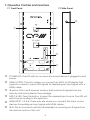
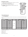
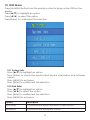
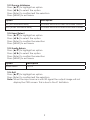
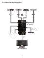
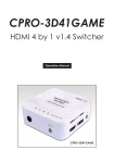
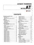
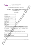
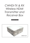
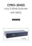
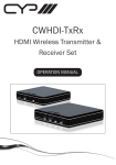
EL-41WX v1.4 Xpressview™ HDMI Wall Mountable 4-Way Switcher OPERATION MANUAL Safety Precautions Please read all instructions before attempting to unpack or install or operate this equipment, and before connecting the power supply. Please keep the following in mind as you unpack and install this equipment: Always follow basic safety precautions to reduce the risk of fire, electrical shock and injury to persons. To prevent fire or shock hazard, do not expose the unit to rain, moisture or install this product near water. Never spill liquid of any kind on or into this product. Never push an object of any kind into this product through module openings or empty slots, as you may damage parts. Do not attach the power supply cabling to building surfaces. Do not allow anything to rest on the power cabling or allow it to be abused by persons walking on it. To protect the equipment from overheating, do not block the slots and openings in the module housing that provide ventilation. Revision History Version No v1.01 Date Summary of Change 10/12/12 Updated RS-232 Command Table of Contents 1. 2. 3. 4. 5. 6. 7. Introduction.................................................................................. 1 Applications................................................................................. 1 Package Contents...................................................................... 1 System Requirements.................................................................. 1 Features........................................................................................ 2 Specifications.............................................................................. 3 Operation Controls and Functions............................................. 4 7.1 Front Panel..................................................................... 4 7.2 Site Panel....................................................................... 4 7.3 Top Panel....................................................................... 5 8. Remote Control............................................................................ 6 9. RS-232 Protocols.......................................................................... 6 9.1 Pin Assignment.............................................................. 6 9.2 Commands.................................................................... 7 10. OSD Menu.................................................................................. 8 10.1 System Info................................................................... 8 10.2 Sink Edid....................................................................... 8 10.3 Source Infoframe........................................................ 9 10.4 Input Select.................................................................. 9 10.5 Audio Return................................................................ 9 10.6 Exit................................................................................. 9 11. Connection and Installation................................................... 10 12. Acronyms................................................................................. 11 1. Introduction This is a high performance four-input & one-output HDMI v1.4 switcher with digital audio inputs and outputs. It supports an HDCP repeater function and fast switching between any of the four HDMI input ports. The system supports all 3D TV formats in addition to all HDTV formats up to 1080p 12-bit Deep Color. Furthermore, the remote control allows every user to easily control selection of sources and its wall mounted design, the installation is an easy and pain free process. 2. Applications Display 3D content Display HDMI v1.4 content Electronic retail display 3. Package Contents HDMI v1.4 3D 4 in 1 out switcher IR Extender Cable Remote Control 5V/1A power adaptor Operation manual 4. System Requirements Input source equipment with or without 3D content and HDMI connection cables. Output HDTV’s with or without 3D support and HDMI connection cables. 1 5. Features Support multiplexed HDMI 4-input and 1-output HDMI 1.4, HDCP 1.4 and CEC compliant HDMI 1.4 support: Audio Return Channel (ARC) 3D TV support CEC Fast switching on all HDMI input ports Character and icon based On-Screen Display (OSD) System information for Software version Sink EDID Source infoframe HDMI input Audio & Audio Return selection HDCP repeater support Deep Color support 36/30/24-bit, 1080p@60Hz HDMI cable distance tested with 1080p 8/12 bits resolution, the input & output distance can run up to 10 &15 meters. Audio support: HDMI 1.4 compatible audio interface Dedicated, flexible audio input/output port Dolby TrueHD DTS-HD Master Audio 7.1CH Full audio input and output support 2 6. Specifications Frequency Bandwidth Input Ports Output port HDMI Output Resolution HDMI Audio Output HDMI Cable In HDMI Cable Out IR Frequency Coaxial Audio Output Power Supply ESD Protection Dimensions (mm) Weight (g) Chassis Material Silkscreen Color Power Consumption Operating Temperature Storage Temperature Relative Humidity 2.25Gbps 4 x HDMI Female ports 1 x HDMI Female port 480i ~1080p 50/60, 1080p24, VGA~WUXGA PCM2, 5.1, 7.1CH, Dolby 5.1, DTS5.1, DD+, D-TrueHD, DTS-HD 1080p 8-bit (10M), 12-bit (10M) 1080p 8-bit (15M), 12-bit (15M) 38KHz PCM2CH, AC3 5V/1A DC (US/EU standards, CE/FCC/UL certified) Or Mini USB power Human Body Model: ± 8kV (air-gap discharge) ± 4kV (contact discharge) 93(W) x148 (D) x 31 (H) 260 Aluminum Silver 4W 0˚C ~ 40˚C / 32˚F ~ 104˚F -20˚C ~ 60˚C / -4˚F ~ 140˚F 20~60% RH (non-condensing) 3 7. Operation Controls and Functions 7.1 Front Panel 7.2 Side Panel ⑥ ① ② EL-41WX ③ ④ ⑤ ① POWER LED: The LED will turn on when the power device is plugged in with power. ② HDMI OUTPUT: This slot is where you connect an HDTV or HD display that supports or doesn’t support 3D signals for displaying an input signal with a HDMI cable. ③ IR sensor: This is an IR receiver window that receives IR signals from the remote control included in the package. ④ INPUT & LED: Press this button to select the desired input source, the LED will switch on according to the selection. ⑤ HDMI INPUT 1~3 & 4: These slots are where you connect the input source devices for sending an input signal with HDMI cables. ⑥ IR IN: This slot connects with the IR extender for receiving an IR signal from the remote control of this unit. 4 Note A. This system was tested with 24AWG cables if using cables of another type, the performance of this system may vary. B. Cable distance tested with a PS3 & 40” Samsung LED LCD TV. C. Figures provided in this manual are for reference only, actual figures may depend on the source and display used along with the cables specifications. 7.3 Top Panel ① ② ③ ④ q DC 5V: Plug the 5V DC power supply into the unit and connect the adaptor to an AC outlet. The LED will switch on when the power cable is plugged in. w USB 5V: This slot is where you can connect the mini USB cable from your PC to supply power. Note: Power supply only support either DC5V or mini USB power. e RS-232: This slot is to connect with a PC or control system with D-Sub 9pin cable for RS-232 control. For detailed RS-232 commands please refer to section 9. r COAX OUT: This slot is where you connect an amplifier for sending an audio signal with coaxial cables. When audio return function is on the audio signal will be received from the output end and when the audio return function is OFF the audio signal will be received from the input source. This device supports PCM 2CH and AC3. Note: A. The display TV or monitor must support an audio return function and the function be must turned on in order to perform properly. B. The display TV or monitor's HDMI input jack must connected to the one with an audio return function. 5 8. Remote Control ① MENU: Press to enter into menu selection, an OSD will appear from the display. ② Enter: Press to confirm the selection. ③ 1, 2, 3, 4: Press to select input port. ④ pqtu: Use these buttons to select/adjust OSD menu’s object. MENU ENTER ① ② ④ 1 2 ③ 3 4 CR-88*A 9. RS-232 Protocols 9.1 Pin Assignment The connection between Switcher and remote controller with RS-232 modem cable. PIN 1 2 3 4 5 6 7 8 9 Switcher Definition NC TxD RxD NC GND NC NC NC NC → ← Baud Rate: 19200 bps Data bit: 8 Bits Parity: None Stop Bit: 1 bit Flow Control: None 6 Remote Controller PIN Definition 1 NC 2 RxD 3 TxD 4 NC 5 GND 6 NC 7 NC 8 NC 9 NC 9.2 Commands (case-insensitive) Command Code s port 1 s port 2 s port 3 s port 4 Response >Select Input Port1 >Select Input Port2 >Select Input Port3 >Select Input Port4 s menu 0 >OSD MENU Off s menu 1 >OSD MENU On s info 0 >OSD System Information Off s menuct u s menuct d s menuct l s menuct r s menuct e s arctx 1 s arctx 0 s reset ST >OSD System Information On >MENU Cursor Up Move >MENU Cursor Down Move >MENU Cursor Left Move >MENU Cursor Right Move >MENU Cursor Enter >ARC mode is on >ARC mode is off >System Reset >Input Port? F/W Vers: 2.5v Command Code Response r port >Select port ? r arctx r fwver >ARC mode is ? >FW Version : Vx.xx s info 1 7 Description Select Input Port1 Select Input Port2 Select Input Port3 Select Input Port4 OFF : No Display On-Screen MENU ON : Display On-Screen MENU OFF : No Display On-Screen System Information ON : Display On-Screen System Information MENU Project Up Move MENU Project Down Move MENU Project Left Move MENU Project Right Move MENU Project Enter ARC Mode Is On ARC Mode Is Off System Reset Status Report Description Show Select Input Port Status Show ARC Mode Status Show Firmware Version 10. OSD Menu Press the MENU button from the remote control to bring up the OSD on the display. Press [p/q] to highlight an option Press [t/ u] to select the option Press [Enter] to confirm/exit the selection 10.1 System Info Press [p/q] to highlight an option Press [Enter] to check the input/output device information and software version. Press [MENU] to exit menu Press [Enter] to confirm/exit the selection 10.2 Sink Edid Press [p/q] to highlight an option Press [t/ u] to select the option Press [Enter] to confirm/exit the selection Press [MENU] to exit menu Option Description Block Data To check the sink Block0 and Block1's table of EDID Description To check the sink description of EDID 8 10.3 Source Infoframe Press [p/q] to highlight an option Press [t/ u] to select the option Press [Enter] to confirm/exit the selection Press [MENU] to exit menu Option Description AVI (AVI infoframe data) To check the source video infoFrame Packet AUD (Audio infoframe data) To check the source audio infoFrame Packet 10.4 Input Select Press [p/q] to highlight an option Press [t/ u] to select the option Press [Enter] to confirm the selection Press [MENU] to exit menu 10.5 Audio Return Press [p/q] to highlight an option Press [t/ u] to select the option Press [Enter] to confirm the selection Press [MENU] to exit menu Option Description Audio Return On/Off 10.6 Exit Press [p/q] to highlight an option Press [Enter] to confirm/exit the selection Note:When the input source is with 3D signal the output image will not display the OSD screen. This is due to the IC limitation. 9 11. Connection and Installation Blu-ray Player HD Receiver 1 2 HD Receiver Media Streamer HDM HDMI HD IInputs Inpu 3 4 EL-41XW E COAXIALARC Ouput IR RS232 Receiver Control Input Input AV Amplifier HDMI Output HDTV (ARC Enabled) 10 A Acronyms Acronym Complete Term HDCP High-bandwidth Digital content protection HDMI High-Definition Multimedia Interface CEC Consumer Electronics Control 11 www.cypeurope.com v1.01