1
01/01
2.13-01
SERVICE
MANUAL
Schaltpläne
/ Circuit
Diagrams,
Page
01/01
Rev.Rev.
2.13-01
SERVICE
MANUAL
Schaltpläne
/ Circuit
Diagrams,
Page
11
x50/67x
– Wildcats
(plus)
– TTX
Laminator–
TDI/STDI/XXtreme
S 45/65/95/105
– TTK/Texxtile
– S– 45/65/95/105
TTX TTX
x50/67x
– Wildcats
(plus)
– TTX
Laminator–
TDI/STDI/XXtreme
– TTK/Texxtile
Schaltpläne
/ CircuitDiagrams
Diagrams
Schaltpläne
/ Circuit
Display-Platine
Schaltplan
Display-Platine
Schaltplan
/ /
Display
Board
Diagram
.................................
Display
Board
Diagram
.................................
2 2
Display-Platine
Bestückung
Display-Platine
Bestückung
/ /
Display
Board
Components...........................
Display
Board
Components...........................
3 3
I/O-Platine:
Schaltplan
Kopfmotor
I/O-Platine:
Schaltplan
Kopfmotor
/ /
Board:
Diagram
Head
Stepper
Motor.....
I/OI/O
Board:
Diagram
Head
Stepper
Motor.....
1313
I/O-Platine:
Schaltplan
Folienmotor
I/O-Platine:
Schaltplan
Folienmotor
/ /
Board:
Diagram
Foil
Stepper
Motor........
I/OI/O
Board:
Diagram
Foil
Stepper
Motor........
1414
CPU-Platine
Schaltplan
CPU
CPU-Platine
Schaltplan
CPU
/ /
CPU
Board
Diagram
CPU
.............................
CPU
Board
Diagram
CPU
.............................
4 4
CPU-Platine
Schaltplan
Speicher
CPU-Platine
Schaltplan
Speicher
/ /
CPU
Board
Diagram
Memory........................
CPU
Board
Diagram
Memory........................
5 5
I/O-Platine:
Schaltplan
Vorschubmotor
I/O-Platine:
Schaltplan
Vorschubmotor
/ /
CPU-Platine
Schaltplan
Schnittstellen
CPU-Platine
Schaltplan
Schnittstellen
/ /
CPU
Board
Diagram
Interfaces
.....................
CPU
Board
Diagram
Interfaces
.....................
6 6
CPU-Platine Bestückung A /
CPU-Platine
Bestückung A /
CPU Board Components A ........................... 7
CPU Board Components A ........................... 7
CPU-Platine Bestückung B /
CPU-Platine Bestückung B /
CPU Board Components B ........................... 8
CPU Board Components B ........................... 8
I/O-Platine: Power Supply, Stepper, Kopf /
I/O-Platine: Power Supply, Stepper, Kopf /
I/O Board: Power Supply, Stepper, Head ...... 9
I/O Board: Power Supply, Stepper, Head ...... 9
I/O-Platine: Schaltplan Stromversorgung /
I/O-Platine: Schaltplan Stromversorgung /
I/O Board: Diagram Power Supply............... 10
I/O Board: Diagram Power Supply............... 10
I/O-Platine: Schaltplan I/O, Kopf /
I/O-Platine:
Schaltplan
KopfHead-Control...
/
I/O Board:
Diagram I/O,
I/O and
11
I/O Board: Diagram I/O and Head-Control... 11
I/O-Platine: Schaltplan Schrittmotor-Logik /
I/O-Platine:
Schaltplan
/
I/O Board:
Diagram Schrittmotor-Logik
Stepper Motor Logic.....
12
I/O Board: Diagram Stepper Motor Logic..... 12
Adapter-Platine
Schrittmotor
Schaltplan
Adapter-Platine
Schrittmotor
Schaltplan
/ /
Adapter
Board
Stepper
Motor......................
Adapter
Board
Stepper
Motor......................
1717
Adapterplatine Laminator /
Adapterplatine
Laminator /
Adapter board laminator .............................. 18
Adapter board laminator .............................. 18
Applikator-Platine Schaltplan /
Applikator-Platine Schaltplan /
Applicator Board Diagram ........................... 19
Applicator Board Diagram ........................... 19
Applikator-Platine Bestückung /
Applikator-Platine Bestückung /
Aplicator Board Components....................... 20
Aplicator Board Components....................... 20
Dispenser-Platine Schaltplan /
Dispenser-Platine Schaltplan /
Dispenser Board Diagram ........................... 21
Dispenser Board Diagram ........................... 21
Messer-Platine Schaltplan /
Messer-Platine
/
Cutter Board Schaltplan
Diagram..................................
22
Cutter Board Diagram.................................. 22
Messer-Platine Bestückung /
Messer-Platine
Cutter Board Bestückung
Components/........................... 23
Cutter Board Components ........................... 23
Operator's Handbook
0 28028
Board:
Diagram
Feed
Stepper
Motor
.....
®
I/OI/O
Board:
Diagram
Feed
Stepper
Motor
.....
1515
Monarch
9906
I/O-Platine
Bestückung
I/O-Platine
Bestückung
/ /
Board
Components................................
PrinterI/OI/OBoard
Components................................
1616
TC9906OH Rev. AB 1/11
©2010 Avery Dennison Corp. All rights reserved.
Each product and program carries a respective written warranty, the only warranty on which the
customer can rely. Avery Dennison Corp. reserves the right to make changes in the product, the
programs, and their availability at any time and without notice. Although Avery Dennison Corp.
has made every effort to provide complete and accurate information in this manual, Avery
Dennison Corp. shall not be liable for any omissions or inaccuracies. Any update will be
incorporated in a later edition of this manual.
2010 Avery Dennison Corp. All rights reserved. No part of this publication may be reproduced,
transmitted, stored in a retrieval system, or translated into any language in any form by any
means, without the prior written permission of Avery Dennison Corp.
WARNING
This equipment has been tested and found to comply with the limits for a Class A digital
device, pursuant to Part 15 of the FCC Rules. These limits are designed to provide reasonable
protection against harmful interference when the equipment is operated in a commercial
environment. This equipment generates, uses, and can radiate radio frequency energy and, if
not installed and used in accordance with the instruction manual, may cause harmful
interference to radio communications. Operation of this equipment in a residential area is likely
to cause harmful interference in which case the user will be required to correct the interference
at their own expense.
CANADIAN D.O.C. WARNING
This digital apparatus does not exceed the Class A limits for radio noise emissions from digital
apparatus set out in the Radio Interference Regulations of the Canadian Department of
Communications.
Le présent appareil numérique n’émet pas de bruits radioélectriques dépassant les limites
applicables aux appareils numériques de la classe A prescrites dans le Réglement sur le
brouillage radioélectrique édicte par le ministère des Communications du Canada.
Trademarks
Monarch and MPCL are trademarks of Avery Dennison Retail Information Services LLC.
Avery Dennison® is a trademark of Avery Dennison Corp.
TrueType is a registered trademark of Apple Computer, Inc.
Other products are trademarks or registered trademarks of their respective countries and are hereby acknowledged.
Avery Dennison Printer Systems Division
170 Monarch Lane
Miamisburg, OH 45342
TABLE OF CONTENTS
GETTING STARTED ........................................................................................................... 1-1
Audience ..................................................................................................................... 1-2
Using this Manual ......................................................................................................... 1-2
Ordering Programmer's Manuals..................................................................................... 1-2
About Monarch® MPCL™ Toolbox Utilities ...................................................................... 1-2
Connecting the Power Cable .......................................................................................... 1-3
Establishing Communications ......................................................................................... 1-3
Connecting the Communication Cable .......................................................................... 1-3
Using the Control Panel................................................................................................. 1-4
Power Save Mode ...................................................................................................... 1-4
Selecting a Function ..................................................................................................... 1-4
Exiting a Function ......................................................................................................... 1-4
LOADING SUPPLIES.......................................................................................................... 2-1
Loading Labels or Tags ................................................................................................. 2-2
Loading Labels for Optional Peel Mode ........................................................................ 2-6
Using Optional Internal Liner Take-Up ............................................................................ 2-8
Removing a Full Liner Take-Up Roll ............................................................................ 2-9
Using the Optional Tear Bar ......................................................................................... 2-10
Adjusting the Printhead Pressure Dials ......................................................................... 2-11
LOADING RIBBON ............................................................................................................. 3-1
Loading Ribbon ............................................................................................................ 3-2
SETTING SUPPLY OPTIONS............................................................................................... 4-1
Setting the Supply Type ................................................................................................ 4-3
Setting the Ribbon ........................................................................................................ 4-4
Using a High Energy Ribbon .......................................................................................... 4-5
High Energy Ribbon Limitations .................................................................................. 4-5
Setting the Speed ......................................................................................................... 4-6
Setting the Feed Mode .................................................................................................. 4-7
Setting the Backfeed ..................................................................................................... 4-8
Changing the Position Settings ...................................................................................... 4-9
Setting the Print Position............................................................................................ 4-9
Setting the Supply Position ....................................................................................... 4-10
Setting the Margin Position ....................................................................................... 4-11
Setting the Dispense Position ................................................................................... 4-12
Setting the Backfeed Distance .................................................................................. 4-13
Using Batch Separators ............................................................................................... 4-14
TOC-i
Using Skip Index......................................................................................................... 4-15
Using Rotate Image .................................................................................................... 4-16
Setting the Print Contrast ............................................................................................ 4-17
SETTING COMMUNICATIONS ............................................................................................. 5-1
Setting the Baud Rate ................................................................................................... 5-2
Setting the Word Length ................................................................................................ 5-3
Setting the Stop Bits ..................................................................................................... 5-4
Setting the Parity .......................................................................................................... 5-5
Setting the Flow Control ................................................................................................ 5-6
Resetting to Default Values ........................................................................................... 5-7
SETTING DEFAULTS ......................................................................................................... 6-1
Setting the Monetary Sign.............................................................................................. 6-2
Setting the Secondary Sign ............................................................................................ 6-3
Setting the Number of Decimal Places ............................................................................ 6-4
Setting the Slashed Zero Appearance ............................................................................. 6-5
Setting the Power-Up Mode ........................................................................................... 6-6
Changing the Prompt Set ............................................................................................... 6-7
Setting the Numeric Format ........................................................................................... 6-8
Examples.................................................................................................................. 6-8
Using Flash Storage...................................................................................................... 6-9
Using Flash Memory.................................................................................................... 6-10
Formatting Flash Memory ......................................................................................... 6-10
Checking Available Flash Memory ............................................................................. 6-11
Packing Flash Memory ............................................................................................. 6-12
Setting the Image Error Mode ...................................................................................... 6-13
Setting the Configuration Packet Mode ......................................................................... 6-14
Setting the Error Retry Mode........................................................................................ 6-15
Memory Guidelines ..................................................................................................... 6-16
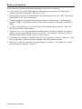
USING SCRIPTS ................................................................................................................ 7-1
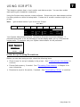
Initial Script Startup Procedures ..................................................................................... 7-1
Viewing Script Information ............................................................................................. 7-2
Downloading a Script .................................................................................................... 7-3
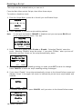
Enabling a Script .......................................................................................................... 7-4
Deleting a Script ........................................................................................................... 7-5
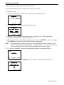
Enabling Status Polling ................................................................................................. 7-5
Enabling Status Polling ................................................................................................. 7-6
Using Immediate Commands .......................................................................................... 7-7
PRINTING ......................................................................................................................... 8-1
Printing........................................................................................................................ 8-1
ii Operator’s Handbook
Printing a Test Label ..................................................................................................... 8-2
On-Demand Mode Printing ............................................................................................. 8-2
Pausing a Batch ........................................................................................................... 8-4
Restarting a Batch ........................................................................................................ 8-4
Canceling a Paused Batch ............................................................................................. 8-4
Canceling a All Batches................................................................................................. 8-5
Repeating a Batch ........................................................................................................ 8-5
Printing TrueType® Fonts .............................................................................................. 8-6
Licensing Your Fonts .................................................................................................... 8-6
CARE & MAINTENANCE ..................................................................................................... 9-1
Clearing Label Jams ..................................................................................................... 9-1
Cleaning ...................................................................................................................... 9-2
Replacing the Printhead ................................................................................................ 9-4
DIAGNOSTICS & TROUBLESHOOTING ............................................................................. 10-1
Factory Set Password ................................................................................................. 10-1
Checking the Software Version..................................................................................... 10-2
Checking Supply Quality .............................................................................................. 10-3
Using Password Protection .......................................................................................... 10-4
Enabling the Password (System Administrators only) .................................................. 10-4
Service Diagnostics .................................................................................................... 10-4
Troubleshooting .......................................................................................................... 10-5
Error Messages .......................................................................................................... 10-6
Common Errors .......................................................................................................... 10-6
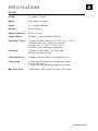
SPECIFCATIONS ..............................................................................................................A- 1
Printer ........................................................................................................................A-1
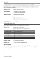
Supplies .....................................................................................................................A- 2
Ribbon Specification ....................................................................................................A- 2
About Ribbons..........................................................................................................A- 2
Cable Pinouts ..............................................................................................................A- 3
ACCESSORIES & OPTIONS .............................................................................................. B- 2
Accessories ................................................................................................................B- 2
Packaging Materials .............................................................................................. ......B- 2
Shipping the Printer .....................................................................................................B- 2
Factory-Installed Options ..............................................................................................B- 2
GLOSSARY ......................................................................................................................G- 1
INDEX ............................................................................................................................. I-1
TOC-iii
iv Operator’s Handbook
1
G E T T I N G S TA R T E D
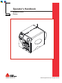
The Monarch® 9906 printer prints text, graphics, and bar codes on thermal transfer
(ribbon) and thermal direct labels or tags. The printer prints labels continuously (in one
strip) or on-demand (one label at a time).
You can print on inside edge aperture, die cut, black mark, or continuous (non-indexed)
supplies. Continuous supply must be used in continuous mode. See "Supply Type" in
Chapter 4 for more information about the supply types.
This chapter includes information about:
connecting the power cord.
connecting the communication cable.
using the printer's control panel.
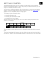
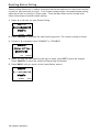
Several chapters of this manual have one or more charts showing the printer's menu
structure. For example:
Main Menu
Canc el
All
S upp ly
Online
B a tch
Entry
R epe a t
B a tch
Format
Op tions
S e tup
Scripts
Contrast
D e fau lts
Port
Settings
F la sh
Memory
RT
C lo ck
Inte rprete r
Dia gno stic s
The solid black box shows where you are; the bordered box and path show how you got
there.
The printer is packaged with a power cord and a ribbon take-up core (may already be on
take-up reel). Keep the box and packaging material in case the printer ever needs repair.
Getting Started 1-1
Audience
The Operator's Handbook is for the person who prints and applies labels.
Using this Manual
Manual content summary:
Chapter
Contents
1
Getting Started
Contains information about connecting the power cable and using the
control panel.
2
Loading Supplies
Describes how to load a roll of supply, fan-fold supply, and tag supply.
3
Loading Ribbon
Describes how to load a roll of ribbon.
4
Setting Supply
Options
Using the Supply menu to set the various supply options (supply,
ribbon, feed mode, etc.).
5
Setting
Communication
Values
Using the Port Settings menu to set the serial and parallel
communication values (baud rate, parity, etc.).
6
Setting Defaults
Using the Defaults menu to set the monetary sign, number of decimal
places, prompt set, etc.
7
Using Scripts
Using the Scripts menu to load a script, enable a script, delete a script,
etc.
8
Printing
Explains how to print labels and use the Pause menu.
9
Care & Maintenance Describes how to clear a label jam, clean the printer, and replace the
printhead.
10 Diagnostics &
Troubleshooting
Describes how to print a test label and lists common problems and
their solutions.
A
Specifications
Contains printer and supply specifications.
B
Accessories &
Options
Contains printer accessories and optional equipment.
Ordering Programmer's Manuals
The 9906 Packet Reference Manual can be downloaded from our Web site. It describes
how to create format and batch packets for printing labels, how to configure the printer
online, how to diagnose printer error messages, and how to perform other advanced
techniques.
About Monarch® MPCL™ Toolbox Utilities
The Monarch® MPCL™ Toolbox utilities are available on our Web site and are free to
download. This group of development utilities helps you configure the printer, customize
fonts, and download files. Monarch MPCL Toolbox utilities are not label production
software. Call Customer Service for information about label production software.
1-2 Operator's Handbook
Connecting the Power Cable
The power supply automatically switches between 115V or 230V. Operator settings are
not required.
1. Plug the power cable into the connection located at the back of the printer. Plug the
other end of the cable into a grounded electrical outlet.
Note:
Only use a certified power cable with proper voltage for the country of
installation.
2. Turn on the printer. Press ( I ) to turn on and ( O ) to turn off the printer.
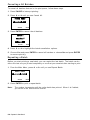
Establishing Communications
Before the printer can accept print jobs from the host, you must:
connect the communication cable to the printer (make sure printer is turned off) and to
the host.
set the communication values on the
printer to match those at the host (only
required if you are using the serial port).
Ask your System Administrator which method
to use for communication with the host:
Serial Communication 9 to 9-pin cable
(Part #126716)
Serial Port
Host USB
T ype A P or t
Optional
Parallel Port/
Ethernet Card
Host USB, Device USB
Parallel Communication (optional)
De vice USB
T ype B P or t
Pow er Cable
Connection
Ethernet (optional)
Connecting the Communication Cable
Connect the communication cable into the appropriate port. Secure the cable with the
connecting screws (serial) or spring clips (parallel).
If you are communicating with the host through the serial port, make sure the printer's
communication values match those at the host. The printer’s default values are 9600
Baud, 8 bit data frame, 1 stop bit, no parity, and DTR flow control.
Getting Started 1-3
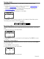
Using the Control Panel
The control panel consists of a four-line LCD display and five buttons. The top three
buttons are function buttons. The function of each button varies depending on the task.
Each button’s function is shown on the display above the button. The two bottom buttons
are navigation buttons. Use these buttons to scroll through menus.
The LCD display:
indicates power when text or other information is shown.
indicates conditions requiring immediate attention
(low battery, faults, errors) using a red background.
shows menu prompts, printer settings,
function button assignments, values, etc.
MPCL
Online
FEED
TLabel
MENU
Function
Buttons
For more information see Chapter 10,
"Diagnostics & Troubleshooting."
Na vigation
Buttons
Power Save Mode
When the printer is idle for longer than 55 minutes, it goes into power save mode, turning
off the display’s back light and all motors. The printer wakes from power save mode
when it receives a format or any button is pressed (printer performs the button’s action).
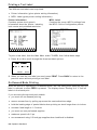
Selecting a Function
The Main Menu has several functions (operating modes). These functions are shown in
the chart below.
Main Menu
Canc el
All
Online
B a tch
Entry
R epe a t
B a tch
Format
Op tions
S e tup
Scripts
S upp ly
Contrast
D e fau lts
Port
Settings
F la sh
Memory
RT
C lo ck
Inte rprete r
To display menu options, press or .
Press SELECT when you see the menu option you need.
Dia gno stic s
The Main Menu controls the printer's setup and operation. Through the Setup Menu, you
can select a sub-menu for the supply, contrast, default, port settings, flash memory, or
real-time (RT) clock. Each of the sub-menus has several options, such as ribbon, speed,
monetary symbols, and baud rate.
Exiting a Function
There are two ways to exit an option. Pressing BACK once exits to the previous menu
and saves any changes. Pressing CANCEL exits to the previous menu; however, changes
are not saved.
1-4 Operator's Handbook
2
LOADING SUPPLIES
This chapter describes how to load:
a roll of supply
fan-fold supply
a roll of tag supply.
There are two types of supplies:
Thermal Direct
specially treated thermal supplies that do not use a ribbon for
printing
Thermal Transfer
standard supplies that require a ribbon for printing
If you are using thermal direct supplies, do not load a ribbon.
If you switch from black mark to die cut supplies, make sure the printer's supply type is
set correctly. See "Supply Type" in Chapter 4 for more information. Your System
Administrator can also send the supply setup packet to change the supply type. Refer to
the optional 9906 Packet Reference Manual for more information about sending the
supply setup packet.
Loading Supplies 2-1
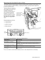
Loading Labels or Tags
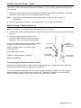
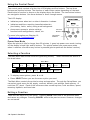
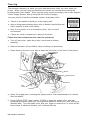
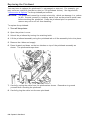
1. Open the cover.
2. Unlock the printhead by turning the retaining latch.
3. Lift the printhead assembly using the printhead tab until the assembly locks into place.
Note: User “touch parts” are yellow.
Printhead Tab
2-2 Operator's Handbook
4. Place rolled supply on the supply holder, located against the inside of the printer.
Rolled label supply unrolls from the top or the bottom; rolled tag supply unrolls from
the bottom only (tag rolls are wound face in).
Note:
Do not pick the printer up by the supply holder.
Supply Holder Guide
Supply
Holder
Place a fan-fold supply stack behind the printer, label side facing up. Lay the label
strip over the supply holder.
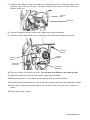
5. Adjust the supply holder guide so that it barely touches the supply, making sure the
supply moves freely.
Loading Supplies 2-3
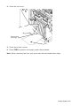
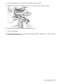
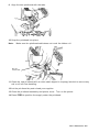
6. Push down on the supply lever to unlock the supply guides.
7. Lay the label strip across the supply guide so that a few inches extend past the front
of the printer. Tuck the supply under the nibs and supply sensor. Do not feed supply
between the supply roller and deflector.
Nibs
Supply Guide
Supply Le ver
Supply
Sensor
8. Adjust the supply guide so it barely touches the supply. Push up on the supply lever
to lock the supply guide into place.
9. Hold the printhead assembly by the printhead tab while pushing the printhead release.
Printhead
Release
Printhead
As sembl y
2-4 Operator's Handbook
10. Close the printhead by pressing down on the thumb well until you hear it click into
place.
11. Close the printer’s cover.
12. Press FEED to position the supply under the printhead.
You may need to adjust the printhead pressure dials depending on the width of
your supply. See "Adjusting the Printhead Pressure Dials” for more information.
Note:
If the printer will be unused for extended periods of time, we recommend leaving
the printhead unlatched.
Loading Supplies 2-5
Loading Labels for Optional Peel Mode
Peel mode is optional and must be purchased separately. In peel mode, the printer
separates the liner from the label. The next label is not printed until the completed one is
removed from the printer. Make sure the printer is configured for on-demand mode and
the correct supply type.
The minimum feed length is 1.5 inches for peel mode. We recommend using 0.5-inch gap
supplies in peel mode when backfeed is disabled. Hold the leading edge of peeled labels
when printing on stock longer than six inches. You must use non-perforated supplies for
peel mode.
Follow the steps for loading supplies from the previous section, close the printhead, and
follow these steps.
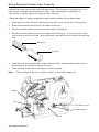
1. Remove the labels from the first 10 inches of the liner.
2. Press down on the exit cover tabs to open the exit cover on the front of the printer.
Exit Cover
3. Feed the liner over the peel roller, along the chute, and out through the lower opening
in the exit cover.
Peel Bar
Platen Roller
Low er Opening
Peel Roller
2-6 Operator's Handbook
4. Close the exit cover.
Saw -Toothed
Tear Edge
Liner
5. Close the printer’s cover.
6. Press FEED to position the supply under the printhead.
Note: When removing the liner, pull up across the saw-toothed tear edge.
Loading Supplies 2-7
Using Optional Internal Liner Take-Up
Internal liner take-up must be used with peel mode. This feature collects the liner on a
take-up reel located inside the printer’s cover. See “Setting the Feed Mode” for
instructions to set the printer for Internal Liner Take-Up.
Follow the steps for loading supplies for peel mode and then follow these steps.
1.
Press down on the exit cover tabs to open the exit cover on the front of the printer.
2.
Remove the labels from the first 18 inches of the liner.
3.
Position the liner take-up reel so the open notch is facing up.
4.
Position the liner take-up core so the open slot is facing up. Line up the slot in the
core with the notch in the reel. Slide the empty liner take-up core on the liner take-up
reel.
Open Notch
Open Slot
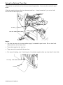
5.
Feed the liner over the peel bar, under the peel roller, under the liner take-up core
and around in a counter-clockwise direction.
7.
Place the end of the liner in the take-up core’s opening.
Note:
Fold the edge of the liner to easily insert it in the core’s open slot.
Supply
Liner
Liner Take-up Core
Liner Take-up Reel
Liner
2-8 Operator's Handbook
8.
Hold the liner in place while turning the take-up reel in a counter-clockwise direction
to remove slack in the supply liner.
9.
Close the printhead assembly until you hear it click in to place.
10. Close the printer’s cover.
11. Close the exit cover.
12. Press FEED to position the supply under the printhead.
Removing a Full Liner Take-Up Roll
Remove the liner take-up when the printer alerts you to a full roll. The liner take-up reel
holds half of a roll of supply. See “Common Errors” in Chapter 10 for more information.
1. Open the cover.
2. Unlock the printhead assembly by turning the retaining latch.
3. Press down on the exit cover tabs to open the exit cover on the front of the printer.
4. Use scissors to cut the liner in front of the take-up reel.
Cut Liner Here
5. Gently pull the full liner take-up core off the reel.
Note:
Place your fingers between the take-up core and printer wall. Gently push the
core off the reel. This eases removal and minimizes the liner telescoping from the
reel.
6. Remove the liner from the take-up core.
7. Reload supply and continue printing.
Loading Supplies 2-9
Using the Optional Tear Bar
The tear bar is optional and must be purchased separately. It can only be used with peel
mode.
Slide the supply between the tear bar and peel bar. It may be easier if you cut or fold
one corner of the supply first.
Tear Bar
Peel Bar
Notes:
The tear bar can only be used when supply is loaded for peel mode. Do not tear both
label and liner at the same time.
Tear labels against the tear bar.
Tags can not be used with the tear bar.
For ease of tearing, use 3-inch long by 1-inch wide supplies that are less than 5 mils thick.
Tear Edge
Liner
2-10 Operator's Handbook
Adjusting the Printhead Pressure Dials
The default setting is least pressure, which provides optimal printing in most cases. If
you see smudging, ribbon wrinkling, or poor print quality, you may need to adjust the
printhead pressure dials.
The two dials are located on
either edge of the printhead
assembly (inside and
outside). The dials may be
set to different positions;
however, the inside dial
should be equal to or more
pressure than the outside
dial. Use a coin or flathead
screwdriver to adjust the
dials.
Inside Printhead
Pressure Dial
Outside Printhead
Pressure Dial
Each dial has four settings:
Least pressure
Light pressure
Medium pressure
Most pressure
Least
Pressure
Most Pressure
Use the following guidelines to adjust printhead pressure.
Supply/Ribbon
Dial Settings
Wide supply (> 2 inches)
Increase both dials one step, check print quality, repeat if
necessary.
Narrow supply (≤ 2 inches)
Increase inside dial one step, check print quality, repeat if
necessary. If uneven printing occurs you may need to increase
the outside dial.
TUFF-MARK® wide (> 2 inches)
Increase both dials to the most pressure setting.
TUFF-MARK® narrow
(≤ 2 inches)
Increase the inside dial to most pressure and the outside dial to
light pressure.
Print a test label to check the printhead pressure; make adjustments as necessary.
Loading Supplies 2-11
2-12 Operator's Handbook
3
LOADING RIBBON
This chapter describes how to load a ribbon roll.
There are different ribbon requirements for the two types of supplies:
Thermal Direct
Supplies
does not use a ribbon for printing
Thermal Transfer
Supplies
requires a ribbon for printing
If you are using thermal direct supplies, do not load a ribbon.
Note:
User “touch parts” are yellow.
Loading Ribbon 3-1
Loading Ribbon
Make sure the printer is configured to use a ribbon.
To load ribbon:
1. Open the cover.
2. Unlock the printhead by turning the retaining latch.
3. Lift the printhead assembly using the printhead tab until the assembly locks into place.
4. Push the deflector tab down.
Take-up
Reel
Printhead
As sembl y
Deflector
Tab
Retaining Latch
5. Slide an empty ribbon core on the take-up reel as far as it will go.
6. Remove the new ribbon from the package. Do not wrinkle or crush the ribbon.
3-2 Operator's Handbook
7. Position the ribbon so that it unwinds in a clockwise direction. Slide the ribbon onto
the back reel as far as it will go. Carefully unwind a few inches of ribbon from the
bottom of the roll.
Take-up
Reel
Back Reel
8. Carefully feed the ribbon under both ribbon rollers and printhead.
9. Align the ribbon and make sure it is straight and centered throughout the path.
Printhead
Release
Ribbon
Roller
Ribbon
Roller
Printhead
As sembl y
Printhead
As sembl y
10. Tape the ribbon to the take-up core. Do not tape the ribbon to the take-up reel.
11. Rotate the take-up core until the leader is past the printhead.
12. Remove any slack in the ribbon by turning the take-up reel clockwise.
13. Hold the printhead assembly by the printhead tab while pushing the printhead release.
14. Close the printhead by pressing down on the thumb well until you hear it click into
place.
15. Close the printer’s cover.
Loading Ribbon 3-3
3-4 Operator's Handbook
4
S E T T I N G S U P P LY O P T I O N S
This chapter explains how to select the supply type, ribbon, speed, feed mode,
backfeed, print position, supply position, margin position, cut position, dispense position,
backfeed distance, separators, skip index mode, rotate image, and print contrast.
Main Menu
Canc el
All
Online
B a tch
Entry
R epe a t
B a tch
Format
Op tions
S e tup
Scripts
S upp ly
Contrast
D e fau lts
Port
Settings
F la sh
Memory
RT
C lo ck
Inte rprete r
S upp ly
Ty pe
Ribbon
S pee d
F eed
Mode
Back fe ed
Position ing
Dia gno stic s
Sepa rato rs
Skip Inde x
Rotate
Image
Your System Administrator may limit access to this menu to prevent changes. You are
prompted to enter a password if password protection is turned on. To continue, ask your
System Administrator for the password.
PASSWORD
*********
ENTER
BACK
The supply options are listed in the table below.
Option
Choices
Default
Supply Type
Aperture/Die Cut/Black Mark/Continuous
Die Cut
Ribbon
No/Yes/High Energy
Yes
Speed
2.5/4.0/6.0/Default
Default
Feed Mode
Continuous/On-Demand/Liner take-up
Continuous
Backfeed
Off/On
Off
Print Position
-450 to +450
0
Supply Position
-300 to 300
0
Margin Position
-99 to 99
0
Dispense Position
50 to 200
65
Backfeed Distance
10 to 100
65
Separators
No/Yes/Long
No
Skip Index
No/Yes
No
Rotate Image
No/Yes
No
To exit an option without changing the setting, press CANCEL.
Setting Supply Options 4-1
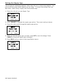
Setting the Supply Type
You can print on inside edge aperture, black mark, die cut, or continuous supplies. You
have to tell the printer which supplies you are using. To access this setting, from the
Main Menu, select Setup, Supply, then follow these steps.
1. Press or until you see Supply Type.
SUPPLY
Supply Type→
Die Cut
CHANGE
BACK
2. Press CHANGE to highlight the supply type options. The current setting is shown.
3. Press or to scroll through the supply type options.
SUPPLY
Supply Type
←
Die Cut
SET
→
CANCEL
4. When you see the supply type you need, press SET to save the change. Press
CANCEL to leave the supply type unchanged.
5. Press BACK until you return to the Home/Online screen.
SUPPLY
Supply Type→
Die Cut
CHANGE
BACK
4-2 Operator's Handbook
Setting the Ribbon
If you are using thermal direct supplies, do not load a ribbon and set the ribbon option to
No. If you are using thermal transfer supplies, load a ribbon and set the ribbon option to
Yes. If you are using high energy supplies (TUFF-MARK®), load a high energy ribbon and
set the ribbon option to High Energy. See "Using a High Energy Ribbon" for more
information.
To change the setting, from the Main Menu, select Setup, then Supply. Then, follow
these steps.
1. Press or until you see Ribbon.
SUPPLY
Ribbon →
Yes
CHANGE
BACK
2. Press CHANGE to highlight the ribbon options. The current setting is shown.
3. Press or to scroll through the ribbon options.
SUPPLY
Ribbon
Yes
SET
→
CANCEL
4. When you see the ribbon option you need, press SET to save the change. Press
CANCEL to leave the ribbon option unchanged.
5. Press BACK until you return to the Home/Online screen.
SUPPLY
Ribbon →
Yes
CHANGE
Note:
BACK
If you choose Yes, install a ribbon before printing. If you choose No, do not
install a ribbon before printing. If you choose High Energy the printer displays
the warning message, “High Energy ribbon can damage the printhead”. Press
ENTER to clear the warning.
Setting Supply Options 4-3
Using a High Energy Ribbon
High energy ribbon is an option for this printer. It enables you to print on high energy
(TUFF-MARK®) supplies.
When you select high energy ribbon for the printer setting, you are setting the printer to a
higher printing temperature. Select this setting only after you have loaded a high energy
ribbon and supplies or it may damage the printhead.
Note:
The high energy setting is lost when you turn off the printer; select a high energy
ribbon every time you turn on the printer.
High Energy Ribbon Limitations
When using the high energy ribbon option:
Use a print speed of 2.5 ips (inches per second).
Printhead warranty is reduced to 100,000 inches.
Serial bar codes cannot be printed.
Do not use peel mode.
No more than 20% of the supply should have print (black coverage).
CAUTION:
The high energy ribbon may break or stick to the supply when more than
20% of the supply contains print.
Only white high energy supply should be used for bar code printing.
Reverse fonts cannot be used.
A non-printing area of at least .1 inch (2.54 mm) must exist on the left and right edge
of the ribbon.
Do not print horizontal lines or bars.
Graphics are limited.
4-4 Operator's Handbook
Setting the Speed
You can change the print speed for bar codes or graphics. If you select "default", formats
with serial bar codes automatically print at 2.5 ips and formats with parallel bar codes
print at 6.0 ips.
Note:
If you change the speed, you must resend your formats or turn the printer off and
back on before the change takes effect.
To change the setting, from the Main Menu, select Setup, then Supply. Then, follow
these steps.
1. Press or until you see Speed.
SUPPLY
Speed →
Default
CHANGE
BACK
2. Press CHANGE to highlight the speed options. The current setting is shown.
3. Press or to scroll through the speed setting options.
SUPPLY
Speed
2.5 IPS
SET
→
CANCEL
4. When you see the speed option you need, press SET to save the change. Press
CANCEL to leave the speed option unchanged.
5. Press BACK until you return to the Home/Online screen.
SUPPLY
Speed →
2.5 IPS
CHANGE
BACK
Setting Supply Options 4-5
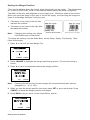
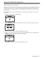
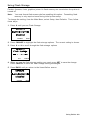
Setting the Feed Mode
You can use continuous, on-demand, or liner take-up printing. On-demand printing allows
you to remove a label before printing the next one. Liner take-up collects the liner on a
take-up reel located inside the printer’s cover. See “Using Optional Liner Take-Up” for
more information.
To change the setting, from the Main Menu, select Setup, then Supply. Then, follow
these steps.
1. Press or until you see Feed Mode.
SUPPLY
Feed Mode→
CHANGE
BACK
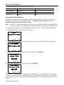
2. Press CHANGE to highlight the feed mode options. The current setting is shown.
3. Press or to scroll through the feed mode options.
SUPPLY
Feed Mode
← On-Demand →
SET
CANCEL
4. When you see the feed mode option you need, press SET to save the change. Press
CANCEL to leave the feed mode option unchanged.
5. Press BACK until you return to the Home/Online screen.
SUPPLY
Feed Mode →
On-Demand
CHANGE
4-6 Operator's Handbook
BACK
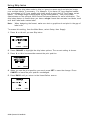
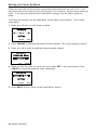
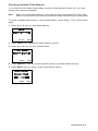
Setting the Backfeed
With backfeed turned on, the printer moves the supply backwards before printing.
To change the setting, from the Main Menu, select Setup, then Supply. Then, follow
these steps.
1. Press or until you see Backfeed.
SUPPLY
Backfeed →
Yes
CHANGE
BACK
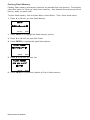
2. Press CHANGE to highlight the backfeed options. The current setting is shown.
3. Press or to scroll through the backfeed options.
SUPPLY
Backfeed
Yes
SET
→
CANCEL
4. When you see the backfeed option you need, press SET to save the change. Press
CANCEL to leave the backfeed option unchanged.
5. Press BACK until you return to the Home/Online screen.
SUPPLY
Backfeed →
Yes
CHANGE
Note:
BACK
If you choose Yes, make sure you use the Positioning menu options to set the
backfeed distance. See “Setting the Backfeed Distance” for more information.
Setting Supply Options 4-7
Changing the Position Settings
This menu includes selections to change the print, supply, margin, dispense, and
backfeed distance positions. To change these settings, from the Main Menu, select Setup,
Supply, Positioning.
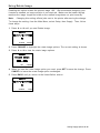
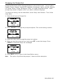
Setting the Print Position
This function adjusts the vertical data printing position. Adjust the position if the print is
too close to the top or bottom of the supply, or overtypes the pre-printed area. One dot
equals 0.0049 inch.
If the data is too close to the bottom,
increase the number.
If the data is too close to the top,
decrease the number.
1. Press or until you see Print Pos.
POSITIONING
← Print Pos →
0
CHANGE
CANCEL
2. Press CHANGE to highlight the print positioning options.
3. Press or to increment/decrement the print position.
Note:
Pressing the left function button changes the increment/decrement amount
(changes by 1, 10, or 100).
POSITIONING
Print Pos
[-450/450] 0
1
SET
CANCEL
4. When you see the print position you need, press SET to save the change. Press
CANCEL to leave the print position unchanged.
5. Press BACK until you return to the Home/Online screen.
POSITIONING
Print Pos →
0
CHANGE
Note:
BACK
Changing this setting only effects new formats sent to the printer.
4-8 Operator's Handbook
Setting the Supply Position
This function adjusts the machine to print at the vertical 0,0 point on the supply. Adjust
the supply in or out to easily remove the supply.
The adjustments are in dots (0.0049 inch).
Increase the number to feed more supply out of the chute.
Decrease the number to feed less supply out of the chute.
Note:
The supply position adjustment should only be made on initial printer setup. For
format adjustments, change the print position.
This option takes effect when you print the next label or tag. Changing supply position
may also affect print position.
1. Press or until you see Supply Pos.
POSITIONING
←
Supply Pos
→
0
CHANGE
CANCEL
2. Press CHANGE to highlight the supply positioning options. The current setting is
shown.
3. Press or to increment/decrement the supply position.
POSITIONING
Supply Pos
[-300/300] 0
1
SET
Note:
CANCEL
Pressing the left function button changes the increment/decrement amount
(changes by 1, 10, or 100).
4. When you see the supply position you need, press SET to save the change. Press
CANCEL to leave the supply position unchanged.
5. Press BACK until you return to the Home/Online screen.
POSITIONING
←
Supply Pos
→
0
CHANGE
BACK
Setting Supply Options 4-9
Setting the Margin Position
This function adjusts where the format prints horizontally on the supply. The adjustments
are in dots (0.0049 inch), which is the smallest measurement the printer recognizes.
The width of the print area depends on your supply size. Maximum width is four inches.
When you move the image to the right or left on the supply, avoid moving the image too
close to either edge, because it may not print.
If the data is too close to the left side,
increase the number.
If the data is too close to the right side,
decrease the number.
Note:
Changing this setting only effects
new formats sent to the printer.
Pri nt too far to the left
Print too far to the right
To change the setting, from the Main Menu, select Setup, Supply, Positioning. Then,
follow these steps.
1. Press or until you see Margin Pos.
POSITIONING
← Margin Pos →
0
CHANGE CANCEL
2. Press CHANGE to highlight the margin positioning options. The current setting is
shown.
3. Press or to increment/decrement the margin position.
POSITIONING
Margin Pos
[-99/99] 0
10
Note:
SET
CANCEL
Pressing the left function button changes the increment/decrement amount
(changes by 1, 10, or 100).
4. When you see the margin position you need, press SET to save the change. Press
CANCEL to leave the margin position unchanged.
5. Press BACK until you return to the Home/Online screen.
POSITIONING
← Margin Pos →
0
CHANGE
4-10 Operator's Handbook
BACK
Setting the Dispense Position
This function adjusts the stopping point of the label.
To access this setting, from the Main Menu, select Setup, Supply, then Positioning.
Follow these steps.
1. Press or until you see Dispense Pos.
POSITIONING
← Dispense Pos →
65
CHANGE
CANCEL
2. Press CHANGE to highlight the dispense positioning options. The current setting is
shown.
3. Press or to increment/decrement the dispense position.
POSITIONING
Dispense Pos
[50/200] 65
10
Note:
SET
CANCEL
Pressing the left function button changes the increment/decrement amount
(changes by 1, 10, or 100).
4. When you see the dispense position you need, press SET to save the change. Press
CANCEL to leave the dispense position unchanged.
5. Press BACK until you return to the Home/Online screen.
POSITIONING
← Dispense Pos →
65
CHANGE
BACK
Setting Supply Options 4-11
Setting the Backfeed Distance
Backfeed distance is the amount the label moves backwards. The backfeed distance
should be equal to or less than the dispense position. If the backfeed distance is greater
than the dispense position then the dispense position automatically changes to match the
backfeed distance.
If you are tearing labels, instead of peeling, the backfeed distance must be 30 dots (0.15
inches) less than the dispense position to account for improper tearing of butt cut
supplies. This causes a 30-dot non-print zone on the supply, but this prevents exposed
adhesive under the printhead.
To access this setting, from the Main Menu, select Setup, Supply, then Positioning.
Follow these steps.
1. Press until you see Backfeed Dist.
POSITIONING
←Backfeed Dist →
65
CHANGE CANCEL
2. Press CHANGE to highlight the backfeed distance options. The current setting is
shown.
3. Press or to increment/decrement the backfeed position.
POSITIONING
Backfeed Dist
[10/200] 65
10
SET
CANCEL
Note: Pressing the left function button changes the increment/decrement amount
(changes by 1, 10, or 100).
4. When you see the backfeed distance you need, press SET to save the change. Press
CANCEL to leave the backfeed distance unchanged.
5. Press BACK until you return to the Home/Online screen.
POSITIONING
←Backfeed Dist→
65
CHANGE
BACK
4-12 Operator's Handbook
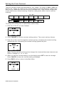
Using Batch Separators
A batch separator is an extra tag printed in between batches with a pinstripe pattern. For
continuous supply, the batch separator is always six inches long. The name of the batch
is shown on the batch separator.
Batch Separator
Note:
Changing this setting only effects new formats sent to the printer.
To change the setting, from the Main Menu, select Setup, then Supply. Then, follow
these steps.
1. Press or until you see Separators.
SUPPLY
← Separators →
No
CHANGE
CANCEL
2. Press CHANGE to highlight the separator options. The current setting is shown.
3. Press or to view the separator options.
SUPPLY
Separators
No
→
SET
CANCEL
4. When you see the separator option you need, press SET to save the change. Press
CANCEL to leave the separator option unchanged.
5. Press BACK until you return to the Home/Online screen.
SUPPLY
← Separators →
No
CHANGE
BACK
Setting Supply Options 4-13
Using Skip Index
You can use the skip index mode to skip (or ignore) a sense mark and print an image
over multiple labels, if necessary. For example, if you have 4.0" long supplies loaded,
but your image is 8.0" long, enable skip index mode to print the 8.0" long image on two
labels. The image length is determined by the format header. See your System
Administrator or the optional 9906 Packet Reference Manual for more information. The
skip index feature is useful when you have a single format that contains two labels, such
as a shelf label and a carton label.
Note:
When designing the format, make sure text or graphics do not print in the gap of
label rolls.
To access this setting, from the Main Menu, select Setup, then Supply.
1. Press or until you see Skip Index.
SUPPLY
← Skip Index →
No
CHANGE
CANCEL
2. Press CHANGE to highlight the skip index options. The current setting is shown.
3. Press or to increment/decrement the print position.
POSITIONING
Skip Index
NO
→
SET
CANCEL
4. When you see the print position you need, press SET to save the change. Press
CANCEL to leave the print position unchanged.
5. Press BACK until you return to the Home/Online screen.
SUPPLY
← Skip Index →
No
CHANGE
BACK
4-14 Operator's Handbook
Using Rotate Image
Enabling this option rotates the printed image 180°. We recommend designing your
formats as needed, so image rotation is not required. Make sure the loaded supply
matches the image length and width or the rotated image does not print correctly.
Note:
Changing this setting effects jobs sent to the printer after saving the change.
To change the setting, from the Main Menu, select Setup, then Supply. Then, follow
these steps.
1. Press or until you see Rotate Image.
SUPPLY
← Rotate Image →
No
CHANGE
CANCEL
2. Press CHANGE to highlight the rotate image options. The current setting is shown.
3. Press or to view the rotate image options.
SUPPLY
Rotate Image
No
→
SET
CANCEL
4. When you see the rotate image option you need, press SET to save the change. Press
CANCEL to leave the rotate image option unchanged.
5. Press BACK until you return to the Home/Online screen.
SUPPLY
← Rotate Image →
No
CHANGE
BACK
Setting Supply Options 4-15
Setting the Print Contrast
The print contrast controls print darkness on your supply. The range is -699 to +699; the
default is 0. Having the correct print contrast setting is important because it affects how
well your bar codes scan and how long your printhead lasts. High contrast settings may
require additional printhead cleaning, create bar code growth, and/or lead to reduced
scanning.
Main Menu
Canc el
All
Online
B a tch
Entry
R epe a t
B a tch
Format
Op tions
S e tup
Scripts
S upp ly
Contrast
D e fau lts
Port
Settings
F la sh
Memory
RT
C lo ck
Inte rprete r
Dia gno stic s
To change this setting from the Main Menu, select Setup.
1. Press or until you see Contrast.
SETUP
← Contrast →
0
CHANGE
BACK
2. Press CHANGE to view the contrast setting options. The current setting is shown.
3. Press or to scroll through the contrast options. Increasing the contrast setting
darkens the print; decreasing the contrast setting lightens the print.
SETUP
← Contrast →
0
10
SET
CANCEL
Note: Pressing the left function button changes the increment/decrement amount (can
adjust to change by 1, 10, or 100).
4. When you see the contrast setting is on the display press SET to save the change.
Press CANCEL to leave the contrast setting unchanged.
5. Press BACK until you return to the Main Menu.
SETUP
← Contrast →
0
CHANGE
BACK
4-16 Operator's Handbook
5
S E T T I N G C O M M U N I C AT I O N S
This chapter tells you how to set the serial communication values. These values
provide the link for normal online printing.
Main Menu
Canc el
All
Online
B a tch
Entry
R epe a t
B a tch
Format
Op tions
S e tup
Scripts
S upp ly
Contrast
D e fau lts
Port
Settings
F la sh
Memory
RT
C lo ck
Inte rprete r
F lo w
contro l
Rese t
Dia gno stic s
S e rial
Comm
Baud Rate
Word
Length
Stop
bits
P a rity
You need to set your Serial Comm values to match your computer's online
communications. Before entering the communication values, see your System
Administrator.
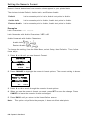
The serial communication values are in the table below.
Option
Choices
Default
Baud rate
1200/2400/4800/9600/19200/
38400/57600/115200
9600
Word length
7/8
8
Stop bits
1/2
1
Parity
None/Odd/Even
None
Flow control
None/Xon/Xoff/DTR/CTS
DTR
Reset
No/Yes
No
Setting Communications 5-1
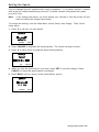
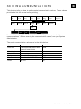
Setting the Baud Rate
Baud rate is the speed, in bits per second, at which the printer sends and receives data.
To change the setting, from the Main Menu select Setup, Port Settings, Serial Comm,
then, follow these steps.
1. Press or until you see Baud Rate.
SERIAL COMM
Baud Rate →
9600
CHANGE
BACK
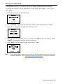
2. Press CHANGE to highlight the baud rate options. The current setting is shown.
3. Press or to scroll through the baud rate options.
SERIAL COMM
Baud Rate
←
9600
SET
→
CANCEL
4. When you see the baud rate you need, press SET to save the change. Press
CANCEL to leave the baud rate unchanged.
5. Press BACK until you return to the Home/Online screen.
SERIAL COMM
Baud Rate →
9600
CHANGE
5-2 Operator's Handbook
BACK
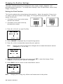
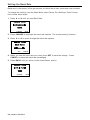
Setting the Word Length
Word length specifies the number of bits the printer uses to define a character.
To access this setting, from the Main Menu select Setup, Serial Comm. Then, follow
these steps.
1. Press or until you see Word Length.
SERIAL COMM
← Word Length →
8
CHANGE
BACK
2. Press CHANGE to highlight the word length options. The current setting is shown.
3. Press or to scroll through the word length options.
SERIAL COMM
Word Length
←
8
SET
→
CANCEL
4. When you see the word length you need, press SET to save the change. Press
CANCEL to leave the word length unchanged.
5. Press BACK until you return to the Home/Online screen.
SERIAL COMM
← Word Length →
8
CHANGE
BACK
Setting Communications 5-3
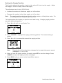
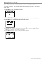
Setting the Stop Bits
A stop bit follows the data and parity bits to signal the end of a character.
To access this setting, from the Main Menu select Setup, Serial Comm. Then, follow
these steps.
1. Press or until you see Stop bits.
SERIAL COMM
← Stop bits →
1
CHANGE
BACK
2. Press CHANGE to highlight the stop bit options. The current setting is shown.
3. Press or to scroll through the desired stop bits options.
SERIAL COMM
Stop bits
←
1
SET
→
CANCEL
4. When you see the stop bits option you need, press SET to save the change. Press
CANCEL to leave the stop bits unchanged.
5. Press BACK until you return to the Home/Online screen.
SERIAL COMM
← Stop bits →
1
CHANGE
BACK
5-4 Operator's Handbook
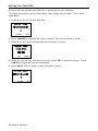
Setting the Parity
Parity checks the validity of data entering the printer. The parity bit immediately follows
the last data bit for a character. The computer adjusts the parity bit according to the
parity so the data bits in the character, with the parity bit, form an odd or even number of
bits.
To access this setting, from the Main Menu select Setup, Serial Comm. Then, follow
these steps.
1. Press or until you see Parity.
SERIAL COMM
← Parity →
None
CHANGE
BACK
2. Press CHANGE to highlight the parity options. The current setting is shown.
3. Press or to scroll through the parity options.
SERIAL COMM
Parity
←
None
SET
→
CANCEL
4. When you see the parity setting you need, press SET to save the change. Press
CANCEL to leave the parity setting unchanged.
5. Press BACK until you return to the Home/Online screen.
SERIAL COMM
← Parity →
None
CHANGE
BACK
Setting Communications 5-5
Setting the Flow Control
Data flow control is the method the printer uses to tell the computer whether it is ready to
accept data. Data Terminal Ready (DTR) flow control is the most common.
To access this setting, from the Main Menu select Setup, Serial Comm. Then, follow
these steps.
1. Press or until you see Flow control.
SERIAL COMM
Flow control →
DTR
CHANGE
BACK
2. Press CHANGE to highlight the flow control options. The current setting is shown.
3. Press or to scroll through the flow control options.
SERIAL COMM
Flow control
←
DTR
SET
→
CANCEL
4. When you see the flow control setting you need, press SET to save the change. Press
CANCEL to leave the flow control unchanged.
Note:
XON is 17; XOFF is 19. Set flow control to DTR for PC computers (unless you
have XON/XOFF software).
5. Press BACK until you return to the Home/Online screen.
SERIAL COMM
Flow control →
DTR
CHANGE
BACK
5-6 Operator's Handbook
Resetting to Default Values
Use this setting to reset the printer’s communication values to the defaults listed at the
beginning of this chapter.
To access this setting, from the Main Menu select Setup, Serial Comm. Then, follow
these steps.
1. Press or until you see Reset.
SERIAL COMM
←
Reset
→
No
ENTER
BACK
2. Press CHANGE to highlight the reset options.
SERIAL COMM
Reset
←
No
→
ENTER CANCEL
3. Press or to scroll through the reset options.
4. When you see the reset option you need, press ENTER. Press CANCEL to leave the
reset option unchanged.
Note:
Selecting "Yes," resets the baud, parity, word length, and stop bit to factory
default.
If you chose yes, to reset the values, press ENTER to verify.
SERIAL COMM
Are you sure?
←
Yes
ENTER
→
BACK
5. Press BACK until you return to the Home/Online screen.
SERIAL COMM
←
Reset
→
No
ENTER
BACK
Setting Communications 5-7
5-8 Operator's Handbook
6
S E T T I N G D E FA U LT S
This chapter explains how to select the monetary sign, secondary sign, decimal
places, slashed zero, power-up mode, prompt set, imaging errors, ignore configuration
packets, and error retry. This chapter also explains how to format flash, check the
available flash memory, and pack flash memory.
Main Menu
Canc el
All
Online
B a tch
Entry
R epe a t
B a tch
Format
Op tions
S e tup
Scripts
S upp ly
Contrast
D e fau lts
S e rial
Comm
F la sh
Memory
R T C lock
Inte rprete r
Mone ta ry
Sign
Seco nda ry
Sign
Decimal
P laces
S lashe d
Zero
Power-up
Mode
Prompt
Set
Numeric
Format
Dia gno stic s
F la sh
Storage
No Image
Error
Ignore
Config
Error
Retry
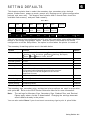
You can set your printer configurations to fit your daily operation, using either the offline
menus or the online configuration option. After an option is selected in the online
configuration or offline Setup Menu, the option is saved when the printer is turned off.
The monetary formatting options are in the table below.
Option
Choices
Default
Monetary sign
None, $ Dollar, £ Pound, ¥ Yen, Deutsche Mark, F Franc,
P Peseta, L. Lira, Kr Krona, Markka, Shilling, Rs Rupee,
Ruble, Won, Baht, ¥ Yuan, € Euro
$ Dollar
Secondary Sign
No/Yes
No
Decimal Places
0/1/2/3
2
Slashed Zero
No/Yes
No
Power-up Mode
Online/Offline
Online
Prompt Set
English/French/German/Spanish-ES/Japanese/
Portuguese/Italian/Swedish/Spanish Latin America/
Danish/Dutch/Finnish/Norwegian/Polish/Turkish/
Simplified Chinese
English
Numeric Format
Default, Arabic-Indic, Eastern Arabic
Default
Flash Storage
Disabled/Enabled
Disabled
No Image Error
Disabled/Enabled
Disabled
Ignore Config
Disabled/Enabled
Disabled
Error Retry
Disabled/Enabled
Enabled
The monetary sign, secondary sign, and decimal places options are used in conjunction
with option 42. Refer to the 9906 Packet Reference Manual for more information.
Note:
The settings for Monetary Sign, Secondary Sign, Slashed Zero, and Decimal
Places apply when a format is downloaded. Changing the settings does not
effect batches already in the printer.
You can also select None if you do not want a monetary sign to print in price fields.
Setting Defaults 6-1
Setting the Monetary Sign
To access this setting, from the Main Menu, select Setup, then Defaults.
Then, follow these steps.
1. Press or until you see Monetary Sign.
DEFAULTS
Monetary Sign →
$ Dollar
CHANGE
BACK
2. Press CHANGE to highlight the monetary sign options. The current setting is shown.
3. Press or scroll through the desired monetary sign options.
DEFAULTS
Monetary Sign
←
$ Dollar
SET
→
CANCEL
4. When you see the monetary sign option you need, press SET to save the change.
Press CANCEL to leave the monetary sign unchanged.
DEFAULTS
Monetary Sign →
$ Dollar
CHANGE
BACK
5. Press BACK until you return to the Home/Online screen.
6-2 Operator's Handbook
Setting the Secondary Sign
If you select the dollar as the monetary sign, you can print amounts less than $1.00 either
by using a dollar sign and decimal ($0.30) or by using a cent sign (30¢).
If you set the secondary sign option to No, prices under $1.00 will print like this: $ .45
If you set the secondary sign option to Yes, prices under $1.00 will print like this: 45¢
The same option applies to the appropriate secondary sign for monetary signs other than
the dollar.
To change the setting, from the Main Menu, select Setup, then Defaults. Then, follow
these steps.
1. Press or until you see Secondary Sign.
DEFAULTS
Secondary Sign→
No
CHANGE
BACK
2. Press CHANGE to highlight the secondary sign options. The current setting is shown.
3. Press or to scroll through the secondary sign settings
DEFAULTS
Secondary Sign
←
No
SET
→
CANCEL
4. When you see the secondary sign setting you need, press SET to save the change.
Press CANCEL to leave the secondary sign setting unchanged.
5. Press BACK until you return to the Home/Online screen.
DEFAULTS
Secondary Sign →
No
CHANGE
BACK
Setting Defaults 6-3
Setting the Number of Decimal Places
You can set the printer for 0, 1, 2, or 3 places after the decimal in a price field. In dollar
currency, you might print prices like this: $24.00 (2 decimal places) or like this: $24 (0
decimal places).
1. Press or until you see Decimal Places.
DEFAULTS
← Decimal Places →
2
CHANGE
BACK
2. Press CHANGE to highlight the decimal place options. The current setting is shown.
DEFAULTS
Decimal Places
←
2
→
SET
CANCEL
3. Press or to scroll through the decimal place options.
4. When you see the decimal place setting you need, press SET to save the change.
Press CANCEL to leave the decimal place setting unchanged.
DEFAULTS
← Decimal Places →
2
CHANGE
BACK
5. Press BACK until you return to the Home/Online screen.
6-4 Operator's Handbook
Setting the Slashed Zero Appearance
The slashed zero feature lets you select how you want the zero character printed; either
without a slash, 0 or, with a slash, Ø.
Standard or reduced fonts print the slashed zero character (Ø). Bold and OCR fonts print
the standard zero (0) only. The slashed zero selection does not take affect until the
format is sent to the printer again. If you change the way zero prints, you must resend
your formats.
To access this setting, from the Main Menu, select Setup, then Defaults. Then, follow
these steps.
1. Press or until you see Slash Zero.
DEFAULTS
← Slashed Zero →
No
CHANGE
BACK
2. Press CHANGE to highlight the slashed zero options. The current setting is shown.
DEFAULTS
Slashed Zero
←
No
SET
→
CANCEL
3. Press or to scroll through the slashed zero options.
4. When you see the slash zero option you need, press SET to save the change. Press
CANCEL to leave the slash zero setting unchanged.
DEFAULTS
← Slashed Zero →
No
CHANGE
BACK
5. Press BACK until you return to the Home/Online screen.
Setting Defaults 6-5
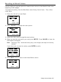
Setting the Power-Up Mode
Power-up mode lets you decide how your printer starts each time you turn it on. If you
want the printer to be ready to start printing when it is turned on, use the Online power-up
mode. If you want the operator enter data before printing, use the Offline power-up
mode.
To change the setting, from the Main Menu, select Setup, then Defaults. Then, follow
these steps.
1. Press or until you see Power-up Mode.
DEFAULTS
← Power-up Mode →
Online
CHANGE
BACK
2. Press CHANGE to highlight the power-up mode options. The current setting is shown.
3. Press or to scroll through the power-up mode options.
DEFAULTS
Power-up Mode
←
Online
SET
→
CANCEL
4. When you see the power-up mode you need, press SET to save the change. Press
CANCEL to leave the power-up mode unchanged.
DEFAULTS
← Power-up Mode →
Online
CHANGE
BACK
5. Press BACK until you return to the Home/Online screen.
6-6 Operator's Handbook
Changing the Prompt Set
Prompt set determines which language displays on the printer's menu. You can select
English, French, German, Spanish-ES, Japanese, Portuguese, Italian, Swedish, SpanishLA, Danish, Dutch, Finnish, Norwegian, Polish, or Turkish Simplified Chinese. Some
prompts may remain in English, even if you select a different language.
To change the setting, from the Main Menu, select Setup, then Defaults. Then, follow
these steps.
1. Press until you see Prompt Set.
DEFAULTS
Prompt Set
→
English
CHANGE
BACK
2. Press CHANGE to highlight the prompt set options. The current setting is shown.
DEFAULTS
Prompt Set
←
English
SET
→
CANCEL
3. Press or to scroll through the prompt set options.
4. When you see the prompt set you need, press SET to save the change. Press
CANCEL to leave the prompt set unchanged.
DEFAULTS
Prompt Set
→
English
CHANGE
BACK
5. Press BACK until you return to the Home/Online screen.
Note:
This option only affects the prompts; it does not affect what prints.
Setting Defaults 6-7
Setting the Numeric Format
Numeric format determines how numeric values appear in your printed data.
The choices include Default, Arabic-Indic, and Eastern Arabic.
Default
Latin numerals print in Latin; Arabic text prints in Arabic.
Arabic-Indic
Latin numerals print in Arabic; Arabic text prints in Arabic.
Eastern-Arabic
Latin numerals print in Arabic; Arabic text prints in Arabic.
Examples
Latin Characters: 95% cotton
Latin Numerals with Arabic Characters:
% 95 ﻗﻄﺐ
Arabic Numerals with Arabic Characters:
Arabic-Indic:
Eastern-Arabic:
To change the setting, from the Main Menu, select Setup, then Defaults. Then, follow
these steps.
1. Press or until you see Numeric Format.
DEFAULTS
← Numeric Format →
Default
CHANGE
BACK
2. Press CHANGE to highlight the numeric format options. The current setting is shown.
DEFAULTS
Numeric Format
←
Default
SET
→
CANCEL
3. Press or to scroll through the numeric format options.
4. When you see the numeric format you need, press SET to save the change. Press
CANCEL to leave the numeric format unchanged.
5. Press BACK until you return to the Home/Online screen.
Note:
This option only affects the prompts; it does not affect what prints.
6-8 Operator's Handbook
Using Flash Storage
Packets (formats, fonts, graphics) stored in flash memory are saved when the printer is
turned off.
Note:
You must format flash memory before enabling this option. Formatting flash
memory is only required once during initial printer setup.
To change the setting, from the Main Menu, select Setup, then Defaults. Then, follow
these steps.
1. Press until you see Flash Storage.
DEFAULTS
← Flash Storage →
Disabled
CHANGE
BACK
2. Press CHANGE to highlight the flash storage options. The current setting is shown.
3. Press or to scroll through the flash storage options
DEFAULTS
Flash Storage
Disabled
SET
→
CANCEL
4. When you see the flash storage setting you need, press SET to save the change.
Press CANCEL to leave the flash storage setting unchanged.
5. Press BACK until you return to the Home/Online screen.
DEFAULTS
← Flash Storage →
Disabled
CHANGE
BACK
Setting Defaults 6-9
Using Flash Memory
The flash memory options are in the table below.
Option
Choices
Default
Format Flash
No/Yes
No
Unused Flash
NA
NA
Pack Flash
No/Yes
No
Formatting Flash Memory
Before storing packets in flash memory, downloading a script, or updating the printer's
firmware, you must format the flash memory. Formatting flash memory is only
required once during initial printer setup.
Note:
When you format flash memory, the script and any downloaded TrueType® fonts
saved in the printer's flash memory are deleted and must be resent to the printer.
To format flash memory, from the Main Menu, select Setup. Then, follow these steps.
1. Press or until you see Flash Memory.
SETUP
← Flash Memory →
SELECT
BACK
2. Press SELECT to highlight the flash memory options. The current setting is shown.
FLASH MEMORY
← Format Flash →
ENTER
BACK
3. Press or until you see Format Flash, then press ENTER.
FLASH MEMORY
Format Flash
← Yes →
ENTER
BACK
4. Press or until you see Yes, then press ENTER.
FLASH MEMORY
Are you sure?
← Yes →
ENTER
BACK
The printer's flash memory is cleared and reformatted. This process may take several
minutes. The printer reboots automatically after formatting flash memory. You need to
resend any fonts you want to use to flash memory again. You return to the Home/Online
screen.
6-10 Operator's Handbook
Checking Available Flash Memory
If you receive errors when downloading a script or other packets, make sure you have
enough flash memory available.
Note:
When you format flash memory, the script and any downloaded TrueType fonts
saved in the printer's flash memory are deleted and must be resent to the printer.
To check available flash memory, from the Main Menu, select Setup. Then, follow these
steps.
1. Press or until you see Flash Memory.
SETUP
← Flash Memory →
SELECT
BACK
2. Press SELECT to highlight the flash memory options.
3. Press or until you see Unused Flash.
FLASH MEMORY
← Unused Flash →
ENTER
BACK
4. Press ENTER to view the current number (bytes) of available flash memory.
5. Press BACK until you return to the Home/Online screen.
FLASH MEMORY
Unused Flash
1006216
ENTER
6
BACK
Setting Defaults 6-11
Packing Flash Memory
Packing flash memory permanently removes any deleted files from memory. Periodically
select this option to "clean up" the printer's memory. Any deleted files are removed from
memory when you pack flash.
To pack flash memory, from the Main Menu, select Setup. Then, follow these steps.
1. Press or until you see Flash Memory.
SETUP
← Flash Memory →
SELECT
BACK
2. Press SELECT to highlight the flash memory options.
3. Press or until you see Pack Flash.
4. Press ENTER to highlight the pack flash options.
FLASH MEMORY
← Pack Flash →
ENTER
BACK
5. Press or until you see Yes.
FLASH MEMORY
Are you sure?
← Yes →
ENTER
BACK
6. Press ENTER to permanently delete all files in flash memory.
6-12 Operator's Handbook
Setting the Image Error Mode
Image errors can occur when there is a problem producing a complete label. Press
ESCAPE to clear an image error.
Image errors include:
600
unable to image batch
614
portion of field off label
601
problem during imaging
615
invalid PDF417 bar code data
603
missing batch
618
invalid font size
611
invalid font, bar code or density
620
missing font data
612
missing batch data
621
invalid downloaded font
613
reference point off label
622
not enough font memory
Note: Enabling image errors means that if a format does not print as expected then no
error is reported. For example, bar codes require a non-print zone; if a bar code is
placed too close to the edge of the label, no error is reported and the bar code may
not scan properly.
Error 616 (bar code dot shifting failed) is always reported.
To change the image error mode setting, from the Main Menu, select Setup, then
Defaults. Then, follow these steps.
1. Press or until you see No Image Error.
DEFAULTS
No Image Error
Enable
CHANGE
BACK
2. Press CHANGE to highlight the image error options. The current setting is shown.
3. Press or to scroll through the image error options.
DEFAULTS
No Image Error
Enableae
SET
CANCEL
4. When you see the image error mode you need, press SET to save the change. Press
CANCEL to leave the image error mode unchanged.
DEFAULTS
No Image Error
Enable
CHANGE
5.
BACK
Press BACK until you return to the Home/Online screen.
Setting Defaults 6-13
Setting the Configuration Packet Mode
You can set how the printer responds to online configuration packets. You can ignore all
online configuration packets by enabling this option. Ignoring these packets is useful
when you cannot change your host’s data or when you want the printer to operate as
specified through the printer’s menu.
Note:
We recommend changing your host’s data stream, but if that is not possible,
enable this option.
Use caution if ignoring online configuration packets, because the printer may
need the configuration for proper operation.
To change the setting, from the Main Menu, select Setup, then Defaults. Then, follow
these steps.
1. Press or until you see Ignore Config.
DEFAULTS
Ignore Config.
Disable
CHANGE
BACK
2. Press CHANGE to highlight the ignore configuration options. The current setting is
shown.
3. Press or to scroll through the ignore configuration options.
DEFAULTS
Ignore Config.
Disablee
SET
CANCEL
4. When you see the ignore configuration mode you need, press SET to save the change.
Press CANCEL to leave the image error mode unchanged.
DEFAULTS
Ignore Config.
Disable
CHANGE
5.
BACK
Press BACK until you return to the Home/Online screen.
6-14 Operator's Handbook
Setting the Error Retry Mode
You can set how the printer operates after a supply error has been cleared. The printer
can either reprint the job or discard/cancel the job. If you enable error retry, the printer
reprints the job that was in process when the error occurred. If you disable error retry, the
printer discards the job that was in process.
To change the setting, from the Main Menu, select Setup, then Defaults. Then, follow
these steps.
1. Press or until you see Error Retry.
DEFAULTS
Error Retry
Enable
CHANGE
BACK
2. Press CHANGE to highlight the error retry options. The current setting is shown.
3. Press or to scroll through the error retry options.
DEFAULTS
Error Retry
Enable
SET
CANCEL
4. When you see the error retry mode you need, press SET to save the change. Press
CANCEL to leave the error retry mode unchanged.
DEFAULTS
Error Retry
Enable
CHANGE
5.
BACK
Press BACK until you return to the Home/Online screen.
Setting Defaults 6-15
Memory Guidelines
Use these basic guidelines when storing files in your printer's memory.
Your printer has volatile RAM (packets deleted when the printer is off and flash
memory (packets saved when the printer is off).
Flash memory must be formatted before any packets can be saved. See "Formatting
Flash Memory" for more information.
Formats, graphics, and check digits can be saved in flash (a copy is automatically
placed in RAM). Any packets saved in flash cannot exceed the memory available in
RAM.
To print International fonts you must have the extended features printer. Save the
font to the printer’s flash memory.
There is not a 1-to-1 ratio between the RAM memory (formats, graphics, and check
digits) in your printer and the memory in your PC. For example, a file that is 5K in
Windows may require 15-20K to store in your printer.
Use temporary storage for graphics that are only used once or twice. However, if you
have a logo that is used on multiple formats, save the graphic in flash.
Each line in a packet requires the same amount of memory. The smaller the format,
the less memory required to save it.
6-16 Operator's Handbook
7
USING SCRIPTS
This chapter explains how to load, enable, and delete scripts. You can also enable
status polling and immediate commands.
Using the Scripts menu requires custom software. Scripts can print data streams written
for other printers or define a lookup table. Contact us to create a custom script for your
printer.
Note:
Ignore these menus if you do not use Scripts.
Main Menu
Canc el
All
Online
B a tch
Entry
R epe a t
B a tch
Format
Op tions
S e tup
Scripts
Dia gno stic s
Load
Script
E nab le
Script
Script
Info
Delete
Script
Status
Po llin g
Immed
Commands
Your System Administrator may limit access to this menu to prevent changes. If
password protection is on, the following is on the display when you try to access the
scripts menu. To continue, ask your System Administrator for the password.
Enter Password
*********
ENTER
BACK
Initial Script Startup Procedures
Before you can start using a script, check the following items:
Check to see if a script is already in the printer. See "Viewing Script Information" to
continue.
Format flash memory, if needed. See "Formatting Flash Memory" in Chapter 6 for
more information.
Download a script to the printer, if needed. See "Downloading a Script" to continue.
Using Scripts 7-1
Viewing Script Information
To see if your printer has a script loaded, from the Main Menu select Scripts, then follow
these steps.
1. Press or until you see Script Info.
SCRIPTS
← Script Info→
ENTER
BACK
2. Press ENTER to highlight the script information options. The current setting is shown.
If a script is not loaded, ENTER is disabled and you must press BACK and return
to the previous menu.
Note:
3. Press or to scroll through the script information options.
SCRIPTS
Script Info
←
XXXX
→
SET
CANCEL
4. When you see the script information you need, Press SET to save the change. What
you see depends on the script. If a script is not loaded, you see "No script loaded." If
a script is loaded, you see the script name and version number.
SCRIPTS
Script Info
←
XXXX
SET
→
BACK
If a script is already loaded, see "Enabling a Script," to continue. If you need to
download a script, see "Formatting Flash Memory" in Chapter 6.
SCRIPTS
← Script Info →
SET
7-2 Operator's Handbook
BACK
Downloading a Script
Follow these instructions to download a script from the MS DOS prompt. Set the
communication parameters using the MODE command. Then, prepare the printer to
accept a script. From the Main Menu select Scripts, then follow these steps.
1. Press or until you see Load Script.
SCRIPTS
← Load Script →
ENTER
BACK
2. Press ENTER to enable the printer’s script communication mode.
Note:
Only one script can be loaded in the printer at a time.
When downloading a script, if you receive an error:
Check the available flash memory. See "Checking Available Flash Memory" in
Chapter 6 for more information.
Format flash memory. See "Formatting Flash Memory" in Chapter 6 for more
information.
After downloading a script, if the script does not appear to be loaded, try formatting flash
memory and download the script again.
Using Scripts 7-3
Enabling a Script
The script must be enabled before you can use it.
From the Main Menu select Scripts, then follow these steps.
To enable or disable a script:
1. From the Script Menu, press or until you see Enable Script.
SCRIPTS
←Enable Script→
Enable
CHANGE
BACK
2. Press CHANGE to view the script enabling options.
If a script is not loaded, CHANGE is disabled and you must press BACK and
return to the previous menu. You see:
Note:
SCRIPTS
←Enable Script→
No Script Loaded
CHANGE
BACK
3. Press or to display either Enable or Disable. Selecting "Enable" starts the
script. Selecting "Disable" stops the script. If you select "Enable," when you turn off
the printer and turn it back on, the script automatically starts.
SCRIPTS
Enable Script
←
Enable
SET
→
CANCEL
4. When you see the script enabling setting you need, press SET to save the change.
Press CANCEL to leave the script enabling setting unchanged.
5. If you select “Enable”, the printer automatically returns to the Home/Online screen and
displays ‘Script’ in the upper left corner to indicate the printer has a script loaded and
enabled.
Script
Online
FEED
TLABEL
MENU
If “Disable” was selected, press CANCEL until you return to the Home/Online screen.
SCRIPTS
←Enable Script→
Disable
SET
7-4 Operator's Handbook
BACK
Deleting a Script
You can delete a script from the printer's memory.
From the Main Menu select Scripts, then follow these steps.
To delete a script:
1. From the Script Menu, press or until you see Delete Script.
SCRIPTS
←Delete Script→
ENTER
BACK
2. Press ENTER to start the script deletion process.
SCRIPTS
Are You Sure?
←
Yes
ENTER
→
BACK
3. Press or to display either Yes or No. Selecting "Yes" deletes the script.
Selecting "No" leaves the script on the printer.
4. When you see the script deletion setting you need, press ENTER to save the change.
Press BACK to leave the script deletion setting unchanged.
The flash memory used by the script is not available for other scripts or fonts
until the flash memory is reformatted. However, when you format flash memory,
you must resend the script and any downloaded fonts to the printer.
Note:
5. If “Yes” was selected, the printer automatically returns to the Home/Online.
Script
Online
FEED
TLABEL
MENU
If “No” was selected, press BACK until you return to the Home/Online screen.
SCRIPTS
Are You Sure?
No
ENTER
BACK
Using Scripts 7-5
Enabling Status Polling
Status polling allows you to obtain information about the readiness of the printer and the
current (or last received) print job. Your System Administrator can enable status polling
while the printer is running in Script mode. From the Main Menu select Scripts then
follow these steps to enable status polling.
1. Press or until you see Status Polling.
SCRIPTS
← Status Polling →
Disable
CHANGE
BACK
2. Press CHANGE to highlight the status polling options. The current setting is shown.
3. Use or to display either "ENABLE" or "DISABLE".
SCRIPTS
← Status Polling →
Disable →
SET
CANCEL
4. When you see the status polling setting you need, press SET to save the change.
Press CANCEL to leave the status polling setting unchanged.
5. Press BACK until you return to the Home/Online screen.
SCRIPTS
← Status Polling →
Disable
CHANGE
7-6 Operator's Handbook
BACK
Using Immediate Commands
Your System Administrator can use immediate commands to reset the printer or cancel
and repeat batches. Immediate commands are turned on or off through an MPCL packet.
Your System Administrator should refer to the 9906 Packet Reference Manual (available
on our Web site) for more information about immediate commands and control characters.
Use this option to set whether the ADK script processes or ignores an immediate
command control character.
To enable the ADK script to process immediate commands, from the Main Menu select
Scripts then follow these steps.
1. Press or until you see Immed Command.
SCRIPTS
← Immed Command →
Disable
CHANGE
BACK
2. Press CHANGE to highlight the immediate command options. The current setting is
shown.
3. Press or to select either "Enable" or "Disable".
"Enable" allows the immediate command control character to be processed by the
printer and performs the requested immediate command.
"Disable" prevents the script and printer from processing the immediate command
control character. Instead, the immediate command control character and
immediate command are treated as data.
SCRIPTS
← Immed Command →
Disable →
SET
CANCEL
4. When you see the immediate command option you need, press SET to save the
change. Press CANCEL to leave the immediate control setting unchanged.
5. Press BACK until you return to the Home/Online screen.
SCRIPTS
← Immed Command →
Disable
CHANGE
BACK
Using Scripts 7-7
7-8 Operator's Handbook
8
PRINTING
This chapter explains how to
use on-demand mode printing.
print, pause, restart, cancel, and repeat a batch.
You can send format, batch, and graphic data to the printer from a host. When the printer
receives the data, batches begin printing automatically. The 9906 Packet Reference
Manual tells how to create, store, and download the data necessary to print batches. You
can also use the Monarch® MPCL™ Toolbox utilities to create and download packets.
Printing
Before you print, make sure the printer is connected and ready to receive data.
1. Turn on the printer. Your printer is ready to receive and print batches when you see:
MPCL
DATA ENTRY
Online
FEED
TLABEL
OR
Select Format
XXXXXXXSSSSSSS
MENU
SELECT
BACK
2. Download a format and a batch. Refer to the 9906 Packet Reference Manual for
information on downloading print jobs.
3. The printer prints a strip of labels.
4. Remove the printed labels.
Note:
If the printer will be unused for extended periods of time, we recommend leaving
the printhead unlatched.
We recommend you check the bar code print quality. A bar code that is in spec has
complete bars, clear spaces, and small alphanumeric characters look complete. An in
spec bar code may not look as good as one that is too dark, but it has the highest scan
rate.
Dark
IN SPEC
Light
Printing 8-1
Printing a Test Label
Two different test labels can be printed:
Printer Information (gives printer setting information)
MPCL Label (gives printer setting information)
Printer Information
Contains system level generic
information about the printer, including
inch counts and printhead resolution.
MPCL Label
Contains the current MPCL settings from
the MPCL Online Configuration packet.
To print a test label, from the Main Menu select TLABEL, then follow these steps.
1. Press or to scroll through the three test label options.
TEST LABEL
Printer Info →
PRINT
BACK
2. When you see the test label you need, press PRINT. Press BACK to return to the
previous menu without printing a test label.
On-Demand Mode Printing
When the printer is operating in on-demand mode, the next label prints when the previous
label is removed or when FEED is pressed. The display shows "Printing X of Y" until all
labels in the batch print.
If you are using the optional peel module:
you must use on-demand printing.
remove excess liner by pulling up across the saw-toothed tear edge.
hold the leading edge of peeled labels when printing on stock longer than six inches.
minimum feed length is 1.5 inches.
you must use non-perforated supplies.
maximum speed is 8.0 ips.
we recommend using 0.5-inch gap supplies when backfeed is disabled.
8-2 Operator's Handbook
Pausing a Batch
Press PAUSE to interrupt printing. You may want to interrupt a batch to make
adjustments for:
Loading a different roll of supply or a ribbon. See Chapter 2, "Loading Supplies" or
Chapter 3, "Loading Ribbon" for more information.
Adjusting the supply position or contrast using the Setup menu. See Chapter 4,
"Setting Supply Options" for more information.
When you press PAUSE, the following is on the display:
PAUSE MENU
← Resume Printing →
ENTER
BACK
Press ENTER to resume printing or press or to display the Pause Menu options.
The following chart shows the Pause Menu options.
Pause Menu
Canc el
B a tch
Canc el
All
Resume
Prin ting
Restart
B a tch
Restarting a Batch
To reprint a paused batch from the beginning (using the original quantity), follow these
steps.
1. Press or until you see Restart Batch.
PAUSE MENU
← Restart Batch →
ENTER
BACK
2. Press ENTER to print the current batch from the beginning. Press BACK to resume
printing.
Canceling a Paused Batch
To cancel a batch, press ESCAPE anytime while the batch is printing or press PAUSE
and follow these steps.
1. Press PAUSE to interrupt printing.
2. Press or until you see Cancel Batch.
PAUSE MENU
← Cancel Batch →
ENTER
BACK
3. Press ENTER to cancel the current batch.
Printing 8-3
Canceling a All Batches
To cancel all batches that are in the print queue, follow these steps.
1. Press PAUSE to interrupt printing.
2. Press or until you see Cancel All.
PAUSE MENU
← Cancel All →
ENTER
BACK
3. Press ENTER to cancel the all batches.
Cancel
Batches?
←
Yes
→
ENTER
BACK
4. Press or to highlight the batch cancellation options.
5. Choose Yes and press ENTER to cancel all batches or choose No and press ENTER
to resume printing.
Repeating a Batch
Before you start printing a new batch, you can reprint the last batch. The batch can be
either the last one you printed completely or one that you canceled after starting to print.
1. From the Main Menu, press or until you see Repeat Batch.
MAIN MENU
← Repeat Batch →
ENTER
BACK
2. Press ENTER to print a repeat batch.
Note:
The number increments until the entire batch has printed. When it is finished,
you return to the Home/Online screen.
8-4 Operator's Handbook
Printing TrueType® Fonts
TrueType® fonts are available on this printer. TrueType fonts are scalable and the
characters print smoothly, without the jagged edges you see on bitmap fonts. When
downloading a TrueType font, you download the entire font. You cannot specify a subset
(particular characters or point size) of the font.
This printer can accept a TrueType font file that has been converted to Hex or RunLength encoding using the version of Font Utility. Font Utility is available on our Web
site. Font Utility is a part of the Monarch MPCL Toolbox Utilities. You can also use a
wide variety of Code Pages with International (Turkish, Latin, Spanish, etc.) characters.
Using TrueType fonts allows you a greater range of fonts for your formats. TrueType
fonts are designed to be regionally specific; therefore, all Code Pages may not be
supported in a given font. Check with your System Administrator if you need to use
TrueType fonts.
Licensing Your Fonts
We provide the Font Utility to help you create and download international code
pages/characters. However, it is your responsibility to license the fonts you purchase
and download to your printer. Contact your font supplier for licensing information.
Additional fonts that are compatible with this printer can be purchased from:
The Electronic Font Foundry; 11 Silwood Road; Ascot; SL5 OPY; England
(0)1344 875 201 www.eff.co.uk
Printing 8-5
8-6 Operator's Handbook
9
CARE & MAINTENANCE
This chapter tells you how to
clear label jams and clean the printer.
replace a printhead.
CAUTION:
Do not use sharp objects to clean the printhead or touch the printhead with
your fingers. This may damage the printer and require a service charge.
Clearing Label Jams
When a jam occurs, the display screen turns red and shows the error code(s). To clear
the jam:
1. Turn off the printer and open the cover and printhead assembly.
2. If necessary, remove the label roll and ribbon.
3. Remove the jammed labels.
4. Reload the label roll and/or ribbon.
4. Close the printhead assembly and turn on the printer.
5. Press FEED to position the supply under the printhead.
Care & Maintenance 9-1
Cleaning
The rate and frequency at which you print determines how often you must clean the
printer. When you are using increased print contrast, we recommend cleaning the
printhead after each ribbon. When you are using continuous supply, the printer displays
“Clean Supply Sensor” after printing 60,000 inches of supply.
You may need to clean the printhead, sensor, and platen roller:
if there is any adhesive build-up in the supply path.
after printing approximately three rolls of thermal transfer/thermal
direct supplies or after each ribbon.
daily if your printer is in an excessively dirty, hot, or humid
environment.
if there are voids or streaking in the print as shown.
Voids
Follow the instructions below to clean the printhead.
1. Turn off the printer, open the printer’s cover and printhead
assembly.
Streaks
2. Remove the label roll and ribbon (when cleaning the printhead).
3. Press down on the exit cover tabs to open the exit cover on the front of the printer.
Sensor
Platen Roller
Peel bar
Exit
Co ver
4. Spray the supply path, including the supply sensor, with compressed air to remove
dust and debris.
5. Use a CLEAN-STRIP (part number 120350) to clean the platen roller, peel bar,
printhead and sensor when you see significant adhesive build-up or after clearing a
jammed label. Turn the platen roller with your finger to make sure it is clean all the
way around. If adhesive remains, call Customer Service.
9-2 Operator's Handbook
6. Once the printer is dry, reload the ribbon and label supplies.
7. Close the exit cover by pushing firmly on it. Both latches click into place.
8. Close the printhead assembly and printer’s cover.
9. Turn on the printer.
10. Press FEED to position the supply under the printhead. Resend your format, batch,
and check digit packets.
Care & Maintenance 9-3
Replacing the Printhead
You may have to replace the printhead if it is damaged or worn-out. For example, you
may see error code 616 (bad dot or dots) or 768 (printhead failure). See Appendix B,
"Accessories & Options" for the printhead part number.
CAUTION:
The printhead is sensitive to static electricity, which can damage it or reduce
its life. Ground yourself by touching metal, such as the printer's metal base,
before touching the printhead. Clean the printhead prior to operation to
remove any salt or oil left from handling.
To replace the printhead:
1. Turn off the printer.
2. Open the printer’s cover.
3. Unlock the printhead by turning the retaining latch.
4. Lift the printhead assembly using the printhead tab until the assembly locks into place.
5. Remove the ribbon and supply.
6. Press forward and down on the two latches on top of the printhead assembly as
shown. The printhead drops down.
7. Carefully unplug the cable from the printhead as shown. Remember to ground
yourself when touching the printhead.
8. Carefully plug the cable into the new printhead.
9-4 Operator's Handbook
9. Align the new printhead with the tabs.
10. Snap the printhead into place.
Note:
Make sure the printhead cable does not touch the ribbon roll.
Do not
touch here
11. Clean the new printhead with a cotton swab dipped in isopropyl alcohol to remove any
salt or oil left from handling.
12. Let the printhead dry and reload your supplies.
13. Close the printhead assembly and printer cover. Turn on the printer.
14. Press FEED to position the supply under the printhead.
Care & Maintenance 9-5
9-6 Operator's Handbook
DIAGNOSTICS & TROUBLESHOOTING
10
This chapter explains how to perform simple diagnostic functions such as checking
the software version and supply quality, printing test labels, and using password
protection. It also contains basic troubleshooting information.
Main Menu
Canc el
All
Online
B a tch
Entry
R epe a t
B a tch
Vers ion
S upp ly
Quality
Format
Op tions
User
Diag.
S e tup
Scripts
Dia gno stic s
S e rv ice
D ia g
P assw o rd
Factory Set Password
A password is required to access the diagnostic functions. Press Feed three times and
then press Enter.
Diagnostics & Troubleshooting 10-1
Checking the Software Version
To view the software version information, from the Main Menu select Diagnostics, then
follow these steps.
1. Press or until you see Version.
DIAGNOSTICS
← Version →
SELECT
BACK
2. Press SELECT to highlight the version options.
3. Press or to scroll through the version options.
VERSION
← Printer →
ENTER
BACK
4. When you see Printer, press ENTER to view the information.
Item 1 is the printer model number.
Item 2 is the software version (press ENTER to view the third item).
Item 3 is the printer serial number.
VERSION
Model M9906
Version 1.0.0.0
ENTER
BACK
VERSION
Serial Number
YYMM1234
ENTER
BACK
5. Press BACK until you return to the Home/Online screen.
10-2 Operator's Handbook
Checking Supply Quality
The printer continuously stores data from 16 of the most recently printed supplies to
check the reflectivity of the sensor marks on the supply. Before you check your supply
quality, print a batch of supplies or test labels.
To check the supply quality, from the Main Menu select Diagnostics, then follow these
steps.
1. Press or until you see User Diag.
DIAGNOSTICS
← User Diag →
SELECT
BACK
2. Press SELECT to highlight the user diagnostics options.
3. Press or to scroll through the user diagnostics options.
DIAGNOSTICS
← User Diag →
← Supply Qual →
ENTER
BACK
4. When you see Supply Quality, press ENTER to view the information.
If you have not printed any labels, the message "No data!" appears. Press BACK
to continue.
You also see the "No data!" message if you are using continuous (non-indexed)
supplies.
If you have printed labels since turning on the printer, the following will display
USER DIAG
Len
Min
Max
OK
← 1568 034
124
Y →
BACK
5. Press or to display the readings.
The Len listing is the length of the loaded supply in dots.
The Max listing should always be greater than the Min listing.
The OK listing tells whether the sense mark on the supply passed a detection test.
6. Press BACK until you return to the Home/Online screen.
Diagnostics & Troubleshooting 10-3
Using Password Protection
The password protection feature prevents formats, graphics or fonts from accidentally
being deleted from the printer's memory. It also limits access to the Setup and Scripts
menus.
Enabling the Password (System Administrators only)
A System Administrator can enable the password that must be entered before formats,
graphics or fonts can be deleted.
To enable the password from the Main Menu select Diagnostics then User Diagnostics.
Then, follow these steps.
1. Press or until you see Password.
USER DIAG
← Password →
ENTER
BACK
2. Press ENTER to enable/disable password protection.
3. Press or to highlight the password options. “No” is the default password
protection setting, therefore it is always shown even if password protection is enabled.
USER DIAG
← Password →
← No →
SELECT
BACK
4. Choose Yes and press SELECT to enable password protection, then proceed
to step 5.
Choose No and press SELECT (or press BACK) to proceed without password
protection. You return to the User Diagnostics menu.
5. Enter the password (press FEED three times then ENTER).
PASSWORD
←**********→
ENTER
Note:
BACK
When password protection is enabled, a password is not required to clear
batches, but it is required to clear formats, graphics, and fonts.
Service Diagnostics
The Service Diagnostics menu can only be accessed by a Service Representative; it
requires a separate password. If you need to call Customer Service, print a test label
first.
10-4 Operator's Handbook
Troubleshooting
This section helps you correct some problems that may occur.
Problem
Action
Error message appears
during startup.
Turn off the printer. Wait fifteen seconds and then turn on the printer.
Call Customer Service if the error message reappears.
Does not print.
Check supply.
Check ribbon.
Send a correct format and batch packet.
Does not feed.
Adjust the printhead pressure dials.
Partially printed data.
Clean the printhead.
Send a correct format packet.
Printing shadows or smears.
Clean the printhead.
Change supply.
Check ribbon.
Light printing.
Change supply.
Adjust the print contrast.
Adjust the printhead pressure dials.
Check ribbon.
Heavy printing.
Clean the printhead.
Change supply.
Adjust the print contrast.
Adjust the printhead pressure dials.
Check ribbon.
Voids in printing.
Clean the printhead.
Change supply type.
Check ribbon.
Serial bar codes do not print.
Leave printhead unlatched when not in use.
Use a print speed of 2.5 IPS.
Adjust the print contrast.
Liner is wrapped around
platen or peel roller.
Carefully remove the liner. Make sure the liner tears at the saw-toothed
tear edge when using backfeed and peel mode.
When downloading a script,
the printer errors.
Check the available flash memory. Format flash memory.
After downloading a script,
the script does not appear to
be loaded.
Try formatting flash memory, then download the script again.
‘Clean Supply Sensor’
message appears when using
continuous supply.
Clean the supply sensor. See "Cleaning" in Chapter 9 for more
information.
If you cannot fix a problem, call Customer Service.
Diagnostics & Troubleshooting 10-5
Error Messages
You may receive the following types of error messages:
Data Errors
Communication Errors
Some errors numbered 400-438 and 500-574 are internal software errors. Errors
numbered 900-999 are hard printer failures. If you cannot clear an error, turn off the
printer, wait several seconds and then turn on the printer. For a complete list of errors,
refer to the 9906 Packet Reference Manual available on our Web site. Call Customer
Service if you need additional assistance.
Common Errors
Errors 001 to 405 and 429 to 435 are data errors. This type of error indicates that
incorrect data was sent to the printer and the printer is ignoring it. Your System
Administrator should correct the packet and send it back to the printer.
Error
Description/Action
002
Name must be 1 to 8 characters (excluding non-printable control
characters) inside quotes.
005
Invalid supply width.
018
Invalid code page selection
025
Data length is too long.
101
Format referenced by batch not in memory.
400
Invalid character following {.
403
Field separator was not found.
409
Printer memory is full. Delete unnecessary formats or graphics from
memory.
410
Parity mismatch.
411
Framing error (baud rate mismatch).
412
Flow control mismatch.
413
Online receive buffer is full. Check for a flow control problem.
611
Font, bar code, or density in the batch does not fit the format.
612
The data in this line of the batch is either missing or does not match the
format.
613
Reference point off supply.
614
Portion of field off supply or there may be an invalid character in the
packet.
703
The printer sensed a calibration of different-sized black marks. Make sure
the correct supply type is loaded.
704
Printer has not sensed a supply mark when expected or is out of supplies.
Make sure your printer is set to the appropriate supply type. Change
supply. Clean the sensor.
750
Printhead is overheated. Turn off the printer.
10-6 Operator's Handbook
751
Printer did not sense a black mark when expected. For errors 751-753,
check the supply tracking, supply marks, black mark sensor position, and
supply roll for binding. Press ESCAPE and try to continue printing.
Change supply.
752
Printer sensed a mark in the wrong place.
753
Printer sensed a mark that is too long.
754
Check for a ribbon jam or remove any slack in the ribbon by turning the
take-up reel clockwise. Load a new ribbon.
755
Printhead is open. Close the printhead.
756
Load supply and/or clean the sensor.
757
Load supply (supply length mismatch), because the calibrated supply
length differs by plus or minus .25 inches from the format. Press FEED.
758
The supply is not seen or the on-demand sensor is broken. Check for a
label jam, clear the supply path, or reload supplies. This error may occur if
you remove a label too quickly in the on-demand mode.
762
Low Voltage. For DC-powered printers, recharge the external battery. For
AC-powered printers, check the power inlet where the printer is connected.
The acceptable voltage range is between 90-132 V RM S and 180-264 V R MS . If
more or less power is received, unpredictable results may occur.
763
Waiting to dispense label. Press FEED.
765
The printhead has less than 8 bad dots. The printer can shift bar code
fields to avoid bad dots. You may need to press ESCAPE to continue
printing. Print a test label to confirm the number of bad dots.
768
Printhead has more than 8 bad dots within the format area or is not
connected. Connect the printhead.
785
The internal liner take-up reel is full. Remove the liner take-up reel and
dispose of the liner. Press ESCAPE to continue printing.
786
Internal liner take-up error. The liner has separated from the core or is not
properly winding on the core. Remove the liner from the take-up core and
reload the liner into the take-up core.
791
The printer has an error pending. Turn off the printer. Wait 15 seconds
(until the power light is completely dim) and turn it back on. Resend the
packets.
Diagnostics & Troubleshooting 10-7
10-8 Operator's Handbook
A
S P E C I F C AT I O N S
Printer
Height:
11 inches (279mm)
Width:
105 inches (267 mm)
Depth:
16.1 inches (409 mm)
Weight:
22 lb. (10 kg)
Shipping Weight:
25 lb. (11.4 kg)
Power Source:
90-264 V AC with autoselect 50/60Hz
Operating Limits:
Thermal Transfer (ribbon): 40° to 95°F (4° to 35°C)
Thermal Direct: 40° to 104°F (4º to 40°C)
Storage: 15°F to 120°F (-10°C to 49°C)
Humidity: 5% to 90% non-condensing
Printhead:
Thermal at 4.09 inches (103 mm) wide
203 dpi (8.0 dots per mm)
Printing Method:
Thermal Transfer (ribbon) or Thermal Direct
Print Speed:
2.5 ips (64 mm) default for all serial bar codes,
4.0 ips (102 mm) or
6.0 ips (152 mm) default for parallel bar codes
Max Print Area:
4.09 inches x 50.0 inches (102 mm x 1270 mm)
Specifcations A-1
Supplies
For high temperature or high humidity environments, contact us for supply
recommendations. Continuous (non-indexed) supply does not have perforations or black
marks and must be used in continuous mode. Aperture supplies are tags or labels with
holes (or openings) in them. The supply is sensed using the holes. The holes can be
only on the edge of the supply.
Supply Types:
Thermal Transfer or Direct
Supply Widths:
0.75 inches (19 mm) minimum
4.5 inches (114 mm) maximum
Supply Lengths:
0.50 inch (13 mm) minimum
50 inches (1270 mm) maximum
Tags
0.50 inch (13 mm) minimum
13.5 inches (343 mm) maximum
Note: Tags must contain perforations.
Total Thickness:
5.5 to 10 mils
Ribbon Specification
Do not leave ribbon in sunlight, high temperatures or humidity.
Ribbon Type:
Standard (wax, high speed)
Premium (wax resin, TUFF-MARK® resin)
Ribbon Widths
Use with Max. supply width
1.5 inches (38 mm)
1.3 inches (33 mm)
1.8 inches (46 mm)
1.5 inches (38 mm)
2.3 inches (58 mm)
2.0 inches (51 mm)
3.3 inches (84 mm)
3.0 inches (76 mm)
3.5 inches (89 mm)
3.2 inches (81mm)
4.3 inches (110 mm)
4.0 inches (102 mm)
4.5 inches (114 mm)
4.5 inches (114 mm)
Ribbon Length:
17,700 inches (450 meters)
Ribbon Core:
1.0 inch (25.4 mm) cardboard core
About Ribbons
The width of the ribbon must be greater than the supply width. Since some supplies are
more abrasive to printheads than others, using a ribbon wider than your supply helps
protect the printhead.
A-2 Operator's Handbook
Cable Pinouts
The following tables show the connector pins for a 9-pin to 9-pin (126716) cable.
9-Pin (M)
To
9-Pin (F)
SHIELD
SHIELD
1
1
RCV 3
3 RCV
TX 2
2 TX
CTS 6
6 CTS
RTS 4
4 RTS
DTR 8
8 DTR
DSR 7
7 DSR
+5V 9
9 +5V
SGND 5
5 SGND
Specifcations A-3
A-4 Operator's Handbook
B
ACCESSORIES & OPTIONS
Accessories
935™ External Rewind
939i™ Intelligent Keyboard
USB mini keyboard (160001)
203 dpi(128933ST) & 300 dpi (12678401) Replacement Printhead Kit
Monarch® MPCL™ Toolbox (utilities to configure the printer, download fonts, and
design formats) available on our Web site
Printhead CLEAN-STRIP (120350)
Printhead Cleaning Pen (114226)
Cables: 9-pin to 9-pin (126716)
9906 Packet Reference Manual – Programmer's manual (TC9906PR)
Packaging Materials
If you need to ship the printer to a different location and do not have the original
packaging, use the following part numbers to order the appropriate packaging materials.
Part Number
Description and Qty.
69601
Shipping carton (1)
69602
Foam cap, front (1)
69603
Foam cap, back (1)
Shipping the Printer
If you need to ship the printer to a different location:
1. Remove the ribbon roll, if one is loaded.
2. Remove the supply roll, if one is loaded.
3. Close the printhead by pressing down on the thumb well until it clicks into place.
4. Place the printer in the original box and secure with packaging material. Make sure
the printer is adequately packed to avoid damage during shipment.
Factory-Installed Options
Internal Ethernet with MonarchNet2™
802.11b/g wireless with MonarchNet2™
Parallel port (IEEE-1284)
300 dpi printhead
ADK script programming for special applications
Tear bar with peel mode
Peel mode with internal liner take-up
Accessories & Options B-1
B-2 Operator's Handbook
G
GLOSSARY
The following terms will help you use this manual.
continuous mode
Mode in which the printer prints all the labels in the batch
without stopping.
download (send)
Transmission of data from the host to your printer.
format
Supply layout or design, which the System Administrator
downloads as a format packet to your printer.
host
Any mainframe, minicomputer, data collect terminal, or personal
computer sending data to the printer.
LCD
Display on the printer used to indicate printer conditions and
problems.
leader
Wrap around a new roll of ribbon with printing on it.
on-demand mode
Mode in which the printer stops after each label to allow you to
remove it.
print job (batch)
Actual data printed on a label or tag. The host may download
the print job together with the format, or as a separate packet.
The print job is also called a "batch."
online
Direct communication between a computer and the printer.
Supply Sensor
Senses whether supply is loaded or needs to be loaded in the
printer. Located in the supply path.
Supplies
Labels used for printing.
System Administrator
Person responsible for creating and downloading packets.
Glossary G-1
G-2 Glossary
INDEX
A
about fonts ....................................................... 8-5
Accessories ......................................................... 2
adjusting
supply width ............................................... 2-11
Adjusting Print Position..................................... 4-8
Adjusting Supply Position .................................. 4-9
Available Memory ........................................... 6-11
B
Backfeed .......................................................... 4-7
Backfeed Distance ........................................... 4-12
Batch ............................................................... 8-3
repeating ...................................................... 8-4
restarting ...................................................... 8-3
Batch Separator .............................................. 4-13
Baud ................................................................ 1-3
Baud Rate ................................................. 5-1, 5-2
C
Cancel
paused batch .......................................... 8-3, 8-4
care & maintenance ........................................... 9-1
Checking
print ............................................................ 8-2
software ..................................................... 10-2
Cleaning Printer ................................................ 9-2
Clearing Jams ................................................... 9-1
Common ........................................................ 10-6
Communication
Errors ........................................................ 10-6
Ethernet ....................................................... 1-3
Parallel ........................................................ 1-3
serial ........................................................... 1-3
Communication Parameters
Baud Rate ..................................................... 5-1
Parity ........................................................... 5-1
Start (XON) Character ................................... 5-1
Stop (XOFF) Character .................................. 5-1
Stop Bits ...................................................... 5-1
Word Length ................................................. 5-1
Contrast
setting ........................................................ 4-16
D
Decimal Places ................................................. 6-4
Default
port settings .................................................. 5-1
Default Values ........................................... 1-3, 5-1
Demand Mode ................................................... 8-1
Diagnostics .................................................... 10-1
Dispense
position ...................................................... 4-11
Dispense Position............................................ 4-11
Display
function buttons ............................................ 1-4
navigation buttons ......................................... 1-4
Distance
backfeed ..................................................... 4-12
Documentation
ordering ....................................................... 1-2
Downloading
scripts .......................................................... 7-3
E
Errors
common ..................................................... 10-6
communication............................................ 10-6
messages .................................................... 10-6
summary .................................................... 10-6
Exiting ............................................................ 1-4
F
feed mode ........................................................ 4-6
Feed Mode ....................................................... 4-6
Flash Memory .................................................. 6-9
Flow Control .................................................... 5-6
Font Licensing ................................................. 8-5
Formatting
flash memory .............................................. 6-10
Function
selecting ...................................................... 1-4
H
high energy ribbon ............................................ 4-4
I
Immediate Commands........................................ 7-7
J
Jams
clearing ........................................................ 9-1
L
labels
adjusting for width ...................................... 2-11
Labels
clearing jams ................................................ 9-1
specifications .................................................. 2
test .............................................................. 8-2
Liner Rewind ................................................... 2-8
Liner Take-Up .................................................. 2-8
Loading
labels ........................................................... 2-2
peel mode ..................................................... 2-6
ribbon .......................................................... 3-2
tags ............................................................. 2-2
Loading Ribbon ......................................... 3-1, 3-2
Loading Supply ................................................ 2-1
M
Maintenance
cleaning printer ............................................. 9-2
Margin Adjustment ......................................... 4-10
Memory ........................................................... 6-9
flash ............................................................ 6-9
Index I-1
storage ......................................................... 6-9
Monetary Sign
defining........................................................ 6-2
MPCL .............................................................. 1-2
O
on-demand printing ........................................... 8-2
Options ............................................................... 2
P
Parity ....................................................... 5-1, 5-5
Password
protection ................................................... 10-4
passwords
setting ........................................................ 10-1
Paused Batch
cancel ................................................... 8-3, 8-4
Peel Mode ........................................................ 2-6
Port Settings..................................................... 5-1
Power Cable ..................................................... 1-3
Connection ................................................... 1-3
Power-Up ......................................................... 6-6
mode ............................................................ 6-6
Print
adjusting position .......................................... 4-8
setting contrast ........................................... 4-16
Print Contrast ................................................. 4-16
Print Speed....................................................... 4-5
Printer
checking status.............................................. 1-4
Control Panel ................................................ 1-4
defaults .............. 4-1, 4-5, 4-14, 5-7, 6-1, 6-2, 6-9
display ......................................................... 1-4
establishing communication ............................ 1-3
operating specifications .................................... 1
operation ...................................................... 1-4
physical specifications ...................................... 1
reset ............................................................ 5-7
setup ............................................................ 1-4
Printer Accessories .............................................. 2
Printer Cleaning ................................................ 9-2
Printer Options .................................................... 2
printhead pressure ........................................... 2-11
Printhead Replacement ...................................... 9-4
printing
on-demand .................................................... 8-2
printing ............................................................ 8-1
Printing
demand mode ................................................ 8-1
True Type fonts ............................................. 8-5
Prompt Set ....................................................... 6-7
R
Reset Defaults .................................................. 5-7
ribbon
high energy ................................................... 4-4
Ribbon ............................................................. 4-3
specifications ................................................... 2
Ribbon Loading ......................................... 3-1, 3-2
Ribbon Specification ............................................ 2
Rotate Image .................................................. 4-15
S
Scripts ...................................................... 7-1, 7-2
I-2 Index
deleting ........................................................ 7-5
downloading ................................................. 7-3
enabling ....................................................... 7-4
Secondary Sign ................................................. 6-3
Selecting a Function.......................................... 1-4
Setting
communication parameters ............................. 5-1
Setting Contrast .............................................. 4-16
Setup Menu ...................................................... 1-4
Skip Index ..................................................... 4-14
Slashed Zero .................................................... 6-5
Software ........................................................ 10-2
Specifications...................................................... 1
ribbon ............................................................. 2
supplies .......................................................... 2
Start (XON) Character ....................................... 5-1
Status Polling ................................................... 7-6
Stop (XOFF) Character ...................................... 5-1
Stop Bits................................................... 5-1, 5-4
supply
options ......................................................... 4-2
Supply
adjusting position .......................................... 4-9
adjusting print options ................................... 4-8
backfeed ...................................................... 4-1
backfeed distance .......................................... 4-1
black mark ................................................... 2-1
die cut ......................................................... 2-1
dispense position........................................... 4-1
fan fold ................................................. 2-1, 2-3
feed mode..................................................... 4-1
margin position ............................................. 4-1
Options ........................................................ 4-1
position ........................................................ 4-9
print options ................................ 4-9, 4-11, 4-12
print position ................................................ 4-1
ribbon .......................................................... 4-1
roll .............................................................. 2-1
separators ..................................................... 4-1
skip index .................................................... 4-1
speed ........................................................... 4-1
supply position ............................................. 4-1
tags ............................................................. 2-1
thermal direct ............................................... 2-1
thermal transfer ............................................ 2-1
type ...................................................... 4-1, 4-2
types ............................................................ 2-1
Supply Loading ......................................... 2-1, 2-2
peel mode ..................................................... 2-6
Ribbon ......................................................... 3-1
Supply Options ................................................. 4-1
Supply Quality ............................................... 10-3
Supply Type ..................................................... 4-2
Supply Types ................................................... 2-1
T
Tag Specifications ............................................... 2
Tear Bar ........................................................ 2-10
tear edge .......................................................... 2-7
Test ................................................................. 8-2
Test Label ........................................................ 8-2
Toolbox Utilities .............................................. 1-2
Troubleshooting...................................... 10-1, 10-5
True Type fonts
printing ........................................................ 8-5
U
default ......................................................... 5-1
Version .......................................................... 10-2
USB ................................................................ 1-3
V
Values
communication .............................................. 5-1
W
wide/narrow knobs .......................................... 2-11
Word Length ............................................. 5-1, 5-3
Index I-3
0 28028
Avery Dennison Printer Systems Division
170 Monarch Lane
Miamisburg, OH 45342
1-800-543-6650 (In the U.S.A.)
1-800-387-4740 (In Canada)
www.monarch.com