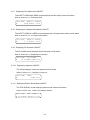
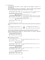
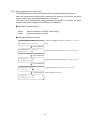
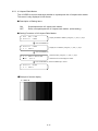
1
LT 4400
MULTIFORMAT VIDEO GENERATOR
Instruction Manual
LEADER ELECTRONICS CORP.
TABLE OF CONTENTS
GENERAL SAFETY SUMMARY .................................................................................................I
1
INTRODUCTION ..................................................................................................................1-1
1.1 Scope of Warranty .........................................................................................................1-1
1.2 Operating Precautions ...................................................................................................1-1
1.2.1
Line Voltage and Fuse ............................................................................................1-1
1.2.2
Maximum Allowable Input Voltage..........................................................................1-2
1.2.3
Shorting the Output Connectors, Reverse Voltage.................................................1-2
1.2.4
Mechanical Shock...................................................................................................1-2
1.2.5
Damage Caused by Static Electricity......................................................................1-2
1.2.6
About the Mounting to the Rack..............................................................................1-2
1.2.7
About the Electric Shock Hazard etc. .....................................................................1-2
1.2.8
About Preheating ....................................................................................................1-2
2
SPECIFICATIONS ................................................................................................................2-1
2.1 General ..........................................................................................................................2-1
2.2 Features.........................................................................................................................2-1
2.3 Specifications.................................................................................................................2-2
2.3.1
SDI Video Output ....................................................................................................2-2
2.3.2
Genlock Function ....................................................................................................2-4
2.3.3
Analog Sync Signal Output .....................................................................................2-5
2.3.4
Word Clock Output..................................................................................................2-6
2.3.5
Memory Card Slot ...................................................................................................2-6
2.3.6
Ethernet Connector.................................................................................................2-6
2.3.7
LCD Panel...............................................................................................................2-6
2.3.8
General Specifications ............................................................................................2-6
2.4 LT 4400-70 (OP70) Full Size Logo Option ....................................................................2-8
2.4.1
General ...................................................................................................................2-8
2.4.2
Features..................................................................................................................2-8
2.4.3
Specifications..........................................................................................................2-8
3
PANEL DESCRIPTION.........................................................................................................3-1
3.1 Front Panel ....................................................................................................................3-1
3.2 Rear Panel.....................................................................................................................3-2
4
OPERATING PROCEDURE.................................................................................................4-1
4.1 Turning Power On..........................................................................................................4-1
4.2 Main Menu .....................................................................................................................4-1
4.3 Menu Keys.....................................................................................................................4-2
4.4 Format Key ....................................................................................................................4-3
4.5 Selecting Pattern Key ....................................................................................................4-5
4.6 KEY LOCK Switch .........................................................................................................4-5
4.7 Upgrading the Firmware ................................................................................................4-6
4.8 Initialization ....................................................................................................................4-10
5
STATUS DISPLAY (STATUS) ..............................................................................................5-1
5.1 Genlock Signal...............................................................................................................5-1
5.1.1
Displaying Status ....................................................................................................5-1
5.2 Analog Black Signal.......................................................................................................5-1
5.2.1
Displaying Format ...................................................................................................5-1
5.3 SDI Signal......................................................................................................................5-1
5.3.1
Displaying Format ...................................................................................................5-1
5.3.2
Displaying Vertical Timing .......................................................................................5-2
5.3.3
Displaying Horizontal Timing...................................................................................5-2
5.3.4
Displaying Embedded Audio Signal ON/OFF .........................................................5-2
5.3.5
Displaying ON/OFF of Y, Cb, and Cr.......................................................................5-2
5.3.6
Displaying Action Safety Area ON/OFF ..................................................................5-2
5.3.7
Displaying Title Safety Area ON/OFF......................................................................5-3
5.3.8
Displaying 4:3 Aspect Ratio Marker ON/OFF .........................................................5-3
5.3.9
Displaying ID Character ON/OFF ...........................................................................5-3
5.3.10
Displaying Logomark ON/OFF ..............................................................................5-3
5.3.11
Displaying Pattern Scroll Mode ON/OFF ..............................................................5-3
6
MAINFRAME SETTING (UTILITY MENU) ...........................................................................6-1
6.1 Setting the Backlight ......................................................................................................6-2
6.1.1
Brightness of the Backlight .....................................................................................6-2
6.1.2
Lighting Time of the Backlight .................................................................................6-3
6.2 Setting the KEY LOCK Mode.........................................................................................6-4
6.3 Setting the Preset Data..................................................................................................6-5
6.3.1
Selecting Media ......................................................................................................6-5
6.3.2
Recalling Preset Data .............................................................................................6-6
6.3.3
Storing Preset Data.................................................................................................6-7
6.3.4
POWER ON RECALL .............................................................................................6-8
6.4 Ethernet Parameters Setup ...........................................................................................6-10
6.4.1
Setting IP Address ..................................................................................................6-10
6.4.2
SUBNET MASK ......................................................................................................6-11
6.4.3
GATEWAY...............................................................................................................6-12
6.5 Passage Day and Time after Turning Power On ...........................................................6-12
6.6 Setting Calendar ............................................................................................................6-13
6.7 Displaying the Version ...................................................................................................6-13
7
GENLOCK SIGNAL SETTINGS (GL SETTING) ..................................................................7-1
7.1 Setting Warning Screen of Unlock Frequency and Log Mode. ......................................7-1
7.1.1
Warning Screen Display..........................................................................................7-1
7.1.2
Recording Log.........................................................................................................7-2
7.1.3
Displaying Log ........................................................................................................7-3
7.1.4
Saving Log ..............................................................................................................7-4
7.2 Setting GENLOCK Mode ...............................................................................................7-5
7.3 Setting GENLOCK TIMING............................................................................................7-7
7.3.1
Timing in Frame Steps............................................................................................7-8
7.3.2
Vertical Timing.........................................................................................................7-8
7.3.3
Horizontal Timing (Course Adjustment) ..................................................................7-9
7.3.4
Horizontal Timing (Fine Adjustment) .......................................................................7-10
8
ANALOG BLACK SIGNAL SETTINGS (BLK SETTING) ......................................................8-1
8.1 Setting Format ...............................................................................................................8-1
8.2 Setting Timing ................................................................................................................8-2
8.2.1
Timing in Frame Steps ............................................................................................8-2
8.2.2
Vertical Timing.........................................................................................................8-3
8.2.3
Horizontal Timing (Dot) ...........................................................................................8-4
8.2.4
Horizontal Timing (Time) .........................................................................................8-5
9
SDI SIGNAL SETTINGS (SDI SETTING).............................................................................9-1
9.1 Setting Format ...............................................................................................................9-2
9.2 Setting Timing................................................................................................................9-2
9.2.1
Vertical Timing.........................................................................................................9-2
9.2.2
Horizontal Timing (Dot) ...........................................................................................9-3
9.2.3
Horizontal Timing (Time) .........................................................................................9-4
9.3 Setting Embedded Audio ...............................................................................................9-5
9.3.1
Sharing Settings Between Groups..........................................................................9-6
9.3.2
Sharing Settings Between Channels ......................................................................9-7
9.3.3
Audio Signal ON/OFF (in each group) ....................................................................9-8
9.3.4
Setting Resolution (in each group)..........................................................................9-9
9.3.5
Setting Pre-Emphasis (in each group) ....................................................................9-10
9.3.6
Setting Frequency (in each group)..........................................................................9-11
9.3.7
Setting Level (in each channel)...............................................................................9-12
9.3.8
Setting Click (in each channel) ...............................................................................9-13
9.4 Setting ON/OFF of Y, Cb, and Cr...................................................................................9-14
9.5 Setting Safety Area Marker............................................................................................9-15
9.5.1
Action Safety Area ..................................................................................................9-15
9.5.2
Title Safety Area......................................................................................................9-16
9.5.3
4:3 Aspect-Ratio Marker .........................................................................................9-17
9.6 Setting ID Character ......................................................................................................9-18
9.6.1
Creating ID Character .............................................................................................9-18
9.6.2
ID Character Position..............................................................................................9-19
9.6.3
ID Character Size....................................................................................................9-20
9.6.4
ID Character Brightness..........................................................................................9-21
9.6.5
Blinking Time of ID Character .................................................................................9-22
9.6.6
Blinking ID Character ..............................................................................................9-23
9.6.7
Displaying ID Character ..........................................................................................9-23
9.7 Setting Logomark...........................................................................................................9-24
9.7.1
Logomark Position ..................................................................................................9-25
9.7.2
Logomark Brightness ..............................................................................................9-26
9.7.3
Penetrating Logomark.............................................................................................9-28
9.7.4
Displaying Logomark ..............................................................................................9-29
9.7.5
Selecting Logomark ................................................................................................9-30
9.7.6
Transferring Logomark............................................................................................9-31
9.7.7
Automatic Transferring Logomark...........................................................................9-32
9.7.8
Saving Logomark ....................................................................................................9-33
9.8 Setting Pattern Scroll .....................................................................................................9-34
9.8.1
Pattern Scroll Direction ...........................................................................................9-34
9.8.2
Pattern Scroll Speed ...............................................................................................9-35
9.8.3
Pattern Scroll Mode ON/OFF..................................................................................9-35
9.9 Setting of Automatic Pattern Changing..........................................................................9-36
9.9.1
Setting of Changing Time........................................................................................9-36
9.9.2
Automatic Pattern Changing ON/OFF ....................................................................9-37
10 WORD CLOCK SETTINGS (WCLK SETTING)....................................................................10-1
10.1 Word Clock Output Level .............................................................................................10-1
10.2 Word Clock Timing .......................................................................................................10-2
11 MENU TREE.........................................................................................................................11-1
11.1 Utility Menu ..................................................................................................................11-1
11.2 GL Setting ....................................................................................................................11-2
11.3 BLK Setting ..................................................................................................................11-3
11.4 SDI Setting...................................................................................................................11-4
11.5 WCLK Setting ..............................................................................................................11-9
12 MAINTENANCE....................................................................................................................12-1
GENERAL SAFETY SUMMARY
■ To Avoid Personal Injury
It is recommended that only qualified personnel with technical knowledge use this instrument
only after reading and fully understanding all functions of the instrument described this
instruction manual.
This instrument is not designed and manufactured for consumers.
If you do not have enough knowledge on electricity, to avoid personal injury and prevent
damage to this product, please be sure to use this product only under the supervision of an
engineer who has sufficient knowledge about electronics.
■ Precautions on Contents
Should you find the contents in this manual and any of its technical terms confusing, please
feel free to contact your local LEADER agent.
■ Symbols and Terms
Following terms and symbols indicate necessary warnings and cautions used in this manual
and on the product are there for safe operation.
<Symbol>
<Term>
WARNING
<Term>
CAUTION
The sections where this symbol is marked in this manual or instrument, if
not correctly performed or practiced, could result in personal injury or
cause serious danger to the instrument. Misuse could also produce
unintentional movement to create an operational impediment on the
instrument or other products that might be connected to it.
Be sure to refer to the safety precautions in this manual to safely use the
part of the instrument where the symbol is marked.
Warning statements identify warning conditions that if disregarded or not
correctly performed or adhered to, could result in serious personal injury
or even loss of life.
Caution statements identify caution conditions that if disregarded or not
correctly performed or adhered to, could result in personal injury or
damage to the instrument.
I
GENERAL SAFETY SUMMARY
Review the following safety precautions to avoid operator's injury and loss of life and prevent
damage and deterioration to this instrument. To avoid potential hazards, use this product as
specified.
WARNING
■ Warnings on the Cases and Panels of the Instrument
Operator should not remove any cases or panel for any reasons. If you touch inside the
instrument it could result personal shock or fire hazard. Refrain from spilling any liquid on
or inserting anything flammables or piece of metal into the ventilation of the instrument.
Such actions could cause fire, shock, malfunction and be an accident hazard while the
power is on.
■ Warnings on Power Line
Make sure to connect only to the rated power line voltage. Excess voltage may cause
fire.
Confirm the voltage of the commercial power line before connecting the AC power
cord.
The power frequency of the power line should be 50/60 Hz.
Warning on the Power Cord
Use only the optional power cord that is attached to this instrument. The use of the
power cord other than that attached could cause fire hazard. If the attached cord is
damaged, stop using it and contact your local LEADER agent. Should you use a
damaged cord, it could cause a shock or create a fire hazard. When you pull out the
cord be sure to hold it by plug and pull from the socket not by holding the cord wire.
■ Warning on Fuse
When the fuse is melted the instrument stops operation. If the fuse melted, please
contact your local LEADER agent.
■ Warning on Installation Environment
● About the Operating Temperature Range
Operate the instrument between the temperature range of 0 to 40 °C. Operating the
instrument at higher temperatures could cause a fire hazard. Be sure not to obstruct air
circulation.
Rapid changes of temperatures from cold to warm can create internal moisture or
condensation and could damage the instrument. If there is a possibility of moisture
condensation, allows the instrument to sit for 30 minutes without the power on.
II
GENERAL SAFETY SUMMARY
WARNING
● About the Operating Humidity Range
Operating humidity range is ≤ 85 % RH. (without condensation)
Do not operate the instrument with wet hands. This could cause a shock and fire
hazard.
● About the Operation in the Presence of Gasses
Operating the instrument in and near the presence or storage locations of flammable,
explosive gasses or fumes could create an explosion and fire hazard. Do not operate
the instrument anywhere near such environments.
● Avoid Insertions
Do not insert metals or flammable objects or drop liquid on or into the instrument. To do so
could cause fire, shock, malfunction and create a dangerous accident hazard.
■ Warning While Operating
While operating the instrument if smoke, fire, or a bad smell occurs, turn off the instrument at
once for it could cause a fire hazard. When such a case occurs, turn off the power switch and
pull the plug of the cord from the plug socket. Contact your local LEADER agent after
confirming there is no fire.
■ Warning About Ground
The instrument has a ground terminal to avoid electric shock hazard and to protect the
instrument from damage. Ensure that the product is properly grounded for safe operation.
■ Warnings Concerning the LCD Panel
Glass is used on the LCD panel. If you break the glass, the fragments may cause injury. Do
not apply strong shock to the glass or damage the surface of the glass with sharp metal
objects.
III
GENERAL SAFETY SUMMARY
CAUTION
■ Caution on Input/Output Terminals
Input terminals are rated with a maximum input. Do not supply an input over the specified
rating in the standard section of the instruction manual. Also, do not supply external power to
Output terminal, this could cause the instrument to malfunction.
■ Caution on AC Adaptor
The instrument that uses the AC adaptor should use the thing surely specified.
If things other than specification are used, there is danger of the instrument malfunction and a
fire.
■ Caution When Not Using the Instrument For a Long Time
Make sure to disconnect the power cord from the socket when you do not use the instrument
for a long time.
■ Caution on Connection of the Instrument and a Display
While the instrument is being connected with a ground terminal of the display, connect or
disconnect the signal cable .
By connecting the ground of the display with the instrument, the output part of the instrument
becomes difficult to break easily.
Be careful especially, when you connect the display under development.
Connect the ground by the following method.
・The ground terminal of the instrument connects with the ground of the display.
IV
GENERAL SAFETY SUMMARY
■ Routine Maintenance
Remove the power cord plug from the socket when cleaning the instrument.
Avoid the use of thinner or benzene solvents for cleaning cases, panels and knobs since this
might remove the paint or damage plastic surfaces.
Wipe cases, panels, and knobs lightly with a soft cloth damped with neutral detergent.
Do not allow water, detergent, or other foreign objects to enter the instrument while cleaning.
If a liquid or metal object enters the instrument, it can cause electric shock or fire.
■ About the Mark by Directive of WEEE in Europe
This product and accessories are object products of European WEEE directive. When you discard
this product and accessories, please process according to the regulation system of each country
and various places.
(WEEE Directive: Waste Electrical and Electronic Equipment)
・・・・・・・・・・・・・・・・・・・・・・・・・・・・・・・・・・・・・・・・・・・・・・・・・・・・・・
Please conform to the above warnings and cautions for safe operation. There are cautions in each
area of this instruction manual, so please conform to each caution.
If you have any questions about this manual, please feel free to contact your local LEADER agent.
V
1 INTRODUCTION
Thank you for purchasing LEADER’s measuring instruments.
Please read this instruction manual carefully to ensure correct and safe operation.
If you have any difficulties or questions on how to use the instrument after you have read this
manual, please feel free to contact your local LEADER agent.
After you have read the manual, keep the manual in a safe place for quick reference.
1.1 Scope of Warranty
This LEADER instrument has been manufactured under the strictest quality control
guidelines. LEADER shall not be obligated to furnish free service during the warranty
period under the following conditions.
1 Repair of malfunction or damages resulting from fire, natural calamity, or improper
voltage applied by the user.
2 Repair of an instrument that has been improperly repaired, adjusted, or modified by
personnel other than a factory-trained LEADER representative.
3 Repair of malfunctions or damages resulting from improper use.
4 Repair of malfunctions caused by devices other than this instrument.
5 Repair of malfunctions or damages without the presentation of a proof of purchase or
receipt bill for the instrument.
1.2 Operating Precautions
1.2.1 Line Voltage and Fuse
WARNING
Confirm that the power line voltage is correct before connecting the power cord.
Usable AC voltage range of an accessory AC adaptor is 100 V to 250 V. The power frequency of
the power line should be 50/60 Hz.
If the fuse melted, please contact your local LEADER agent after confirming there is no
fire. (A fuse is in the power supply circuit inside the instrument.)
The voltage range of the DC power supply is 10 V to 18 V. Do not apply voltage
exceeding this range as it can cause a malfunction or fire.
1-1
1.2.2 Maximum Allowable Input Voltage
CAUTION
The maximum allowable input voltage to the input connectors is shown in the table 1-1
below. Do not apply excessive voltage to prevent damage to the instrument.
Table 1-1
Maximum allowable input voltage
Input Connector
GENLOCK
Maximum Input Voltage
±4.5V (DC + peak AC)
1.2.3 Shorting the Output Connectors, Reverse Voltage
Do not short any output connectors to prevent damage the instrument.Do not supply
external power to Output terminal, this could cause the instrument to malfunction.
Otherwise, you may damage the instrument or other property.
1.2.4 Mechanical Shock
Please be careful not to expose the instrument to other forms of severe mechanical
shock as this product contains shock sensitive precise parts.
1.2.5 Damage Caused by Static Electricity
Electronic parts are susceptible to damage from electrostatic discharge (ESD). The core
wire of the coaxial cable may be charged with static electricity. If you are connecting a
coaxial cable that is not connected on either end to an input/output connector of the
instrument, short the cable’s core wire and external conductor beforehand.
1.2.6 About the Mounting to the Rack
When you mount the instrument to the rack, be sure to prepare the mechanical parts
supporting main body.
In addition, the rail supporting a main body is prepared as an option goods.
1.2.7 About the Electric Shock Hazard etc.
When you perform an examination and adjustment of a television, VTR, and other
related devices, refer to the service manual of each device.
When you connect this instrument to the inside of a device to be measured, be sure to
remove that power cord from a socket, and an electric shock hazard should not occur.
Especially when you connect this instrument to the device which contains high-voltage
circuits, such as television, wears the glove which endures the high voltage and be
careful of it not to get an electric shock.
1.2.8 About Preheating
To secure more accurate operation, turn on the power before about 30 minutes of use,
and stabilize an internal temperature.
1-2
2 SPECIFICATIONS
2.1 General
The 1U half-rack sized compact LT 4400 Multiformat Video Generator applicable to both
HD-SDI and SD-SDI systems outputs SDI video signals.
The various output capabilities are provided: color bar, SDI check field test pattern, ID
characters, logomark in QVGA size(*1), safety-area marker, superimposing embedded
audio, genlock mode to synchronize external reference signal, and three independent
analog black signal systems.
*1 Up to 1920 dots x 1080 lines can be displayed when the Option (LT 4400-70) is
installed.
2.2 Features
● Applicable to both HD-SDI and SD-SDI systems
Applicable to both HDTV (18 types of HDTV formats) and SDTV (525i/59.94,
625i/50) systems. The HDTV or SDTV can be selected.
● Superimposing ID characters
The ID characters can be superimposed at the arbitrary position on the screen. The
character blinks to indicate the freeze status.
● Superimposing logomark
The logomark up to 320 dots x 240 lines in QVGA size(*1) can be superimposed at
the arbitrary position on the screen. The logomark is converted from the bit map to
four-grade monochrome data.
● Safety-area marker
The 90 % and 80 % safety-area markers can be superimposed on the screen.
The 4:3 aspect-ratio marker can also be superimposed in HDTV format.
● Superimposing embedded audio
The 16 channels of embedded audio signals (4 channels x 4 groups) can be
superimposed. The frequency and level can be respectively set to each channel.
● Genlock mode
This instrument can be locked by the NTSC/PAL black burst signals and HDTV
tri-level sync signal for variable the timing. The NTSC/PAL black burst signals with
field reference pulse signal, and NTSC/PAL black burst signal with 10-field ID are
also applicable.
● Stay-in sync function
This function ensures the stable operation in genlock mode even when the external
reference signal is accidentally intermitted.
● Analog black signal output
Three independent analog black signal output systems are provided. The black
burst signal with the same format as the SDI output, or HDTV tri-level sync signal
with the same format of clock frequency can be selected for variable the timing. The
NTSC/PAL black burst signals with field reference pulse signal, and NTSC black
burst signal with 10-field ID are also applicable.
● Pattern scroll (Simple motion picture mode)
The simple motion picture mode is provided to scroll the pattern.
● Word clock output
The 48 kHz word clock output is provided to synchronize the audio signal.
2-1
● Applicable to SNMP
The network system can easily be constructed since this instrument supports SNMP.
(Not available currently)
2.3 Specifications
2.3.1 SDI Video Output
SDI Characteristics
Bit Rate:
Output Amplitude:
Overshoot:
Rise and Fall Times:
DC Offset:
Output Impedance:
Return Loss:
Number of Outputs:
Output Connector:
Conform To
HDTV:
SDTV:
Applicable Format
HDTV:
SDTV:
Variable Timing
Variable Range:
Setting
V:
H:
Test Patterns
HDTV:
SDTV:
1.485Gbps, 1.485/1.001Gbps, or 270Mbps
800mVp-p±10%
≤10%
≤270ps (between 20% and 80%)
(HDTV)
0.4 to 1.5 ns (between 20 % and 80 %)
(SDTV)
0V±0.5V
75 Ω
≥15dB (5MHz to 742.5MHz)
≥10 dB (742.5 MHz to 1.485 GHz)
1 system, 2 outputs (HD-SDI/SD-SDI selectable)
BNC
SMPTE 274M, SMPTE 296M, and SMPTE 292M (Except
for Return Loss)
ITU-R BT 601, SMPTE 125M, ITU-R BT 656, and SMPTE
259M
1080i/60, 1080i/59.94, 1080i/50, 1080p/30, 1080p/29.97,
1080p/25, 1080p/24, 1080p/23.98, 1080PsF/24,
1080PsF/23.98, 720p/60, 720p/59.94, 720p/50, 720p/30,
720p/29.97, 720p/25, 720p/24, 720p/23.98
525i/59.94-270MHz, 625i/50-270MHz
Entire frame range
Settable in line steps
Settable in clock steps (74.25MHz, 74.25/1.001MHz,
27MHz)
100%/75% COLOR BAR
MULTIFORMAT COLOR BAR (ARIB STD-B28)
(Pattern 2 Section: 100% White/ 75% White/ +I
selectable)
CHECK FIELD
100% COLOR BAR (applicable to both 525i/59.94,
625i/50)
75% COLOR BAR/ SMPTE COLOR BAR (applicable to
525i/59.94)
EBU COLOR BAR/ BBC COLOR BAR (applicable to
625i/50)
2-2
CHECK FIELD (applicable to both 525i/59.94, 625i/50)
Safety Area Marker
HDTV:
SDTV:
Action safety area (90%)
Title safety area (80%)
4:3 aspect ratio
Selectable ON/OFF individually
Action safety area (90%)
Title safety area (80%)
Selectable ON/OFF individually
ID Characters
Number of Characters:
Up to 20 characters
Size:
32x32/ 64x64/ 128x128 dots selectable
Display Position:
Displays at an arbitrary position on the screen
Freeze Confirmation
Display:
Blinking OFF, 1 to 9 seconds
Logomark
Logomark Data:
4-level monochrome data between 0 and 3
Maximum Size:
320 dots × 240 lines (QVGA size) (*1)
Display Position:
Displays at an arbitrary position on the screen
Display Level:
Set arbitrary levels for levels 0 to 3
Simultaneous Display with
the ID Character:
Simultaneous display with the ID character
File Format
Before Conversion:
24-bit full-color bitmap data (.bmp) format
After Conversion:
LT 4400/ LT 443D dedicated (.lg) format
Conversion Color Matrix: Y = 0.212 *R + 0.701 *G + 0.087 *B
Converts 256-level monochrome data (Y) to four levels
(levels 0 to 3) using arbitrary threshold values.
Conversion Method:
Converted using the logo mark conversion application.
Transferring the Logo Mark
Data:
Saves the data to a commercially sold Compact Flash
card and inserts it to the LT 4400. (*2)
Pattern Scroll (Simple
Motion Picture Mode)
Direction:
8 directions (vertical, horizontal, diagonal)
Speed (Range,
Resolution)
V:
0 to 255 lines in 1 line steps
H:
0 to 254 dots in 2 dot steps
Embedded Audio (*3)
Number of Channels
Embedded:
16 ch (4ch x 4group) Each group can be set ON/OFF
Sampling Frequency:
48 kHz (sync to video signal)
Resolution:
20 bits, or 24 bits, selectable (*4)
Pre-emphasis:
OFF, 50/15 µs, or CCITT, selectable (CS bit can only be
selected)
Frequency:
SILENCE/400Hz/ 800Hz/ 1kHz, selectable (sets to each
channel)
2-3
Level:
Audio Click:
-60 to 0 dBFS, in 1 dBFS steps (sets to each channel)
1 sec/2 sec/3 sec/4 sec/OFF, selectable (sets to each
channel)
*1 Up to 1920 dots x 1080 lines can be displayed when the Option (LT 4400-70) is
installed.
*2 The data loaded from CF card to the LT 4400 cannot be held when the power is turned
OFF.
*3 When the CHECK FIELD pattern is selected, no audio signal is embedded.
*4 When the input format is SD and makes it 24 bits, the number of the output channels
becomes up to 12 channels (3group).
2.3.2 Genlock Function
Reference Input Signal
Input Configuration:
BNC (75Ω, loop through)
Signal Standards
NTSC black burst signal: SMPTE RP154, SMPTE 170M, SMPTE 318M
PAL black burst signal:
EBU N14, ITU-R BT.470-6
HDTV tri-level sync:
SMPTE 274M, SMPTE 296M
Sync Level
NTSC black burst signal: -286mV
PAL black burst signal:
-300mV
HDTV tri-level sync:
±300mV
Maximum Allowable Input
Voltage:
± 4.5V (DC + peak AC)
Operating Input Level Range:
±6 dB
External Lock Range:
± 10 ppm
Jitter
Burst Lock Mode:
≤ 0.5°
Sync Lock Mode:
≤ 1ns
Operation Modes
INTERNAL:
AUTO (GO INTERNAL):
MANUAL (GO INT):
AUTO (STAYinSYNC):
Internal reference signal is used for operation. (INT
mode)
The EXT is automatically selected when the external
reference signal is applied to the GENLOCK input. The
INT mode is automatically selected when the external
reference signal is removed.
The EXT mode is automatically selected when the
external reference signal with the same format specified
to the GENLOCK input is applied after power is turned on.
The INT mode is automatically selected when no external
reference signal is applied to the GENLOCK input or
signal format does not match the specified format.
The EXT mode is automatically selected when the
external reference signal is applied to the GENLOCK
input after power is turned on. If the external reference
signal is accidentally removed during operation, the
instrument continues operation under the conditions
2-4
immediately before the signal is removed since
STAYinSYNC mode is provided. After the external
reference signal is recovered, the system is automatically
locked.
MANUAL (STAYinSYNC):
Genlock Timing
Variable Range
NTSC black burst
signal:
PAL black burst
signal:
HDTV tri-level sync:
Resolution
H:
V:
F:
Reference Point at the
time of the NTSC black
burst input:
Reference Point at the
time of the PAL black
burst input:
The EXT mode is automatically selected when the
external reference signal with the same format specified
to the GENLOCK input is applied after power is turned on.
If the external reference signal is accidentally removed
during operation, the instrument continues operation
under the conditions immediately before the signal is
removed since STAYinSYNC mode is provided. The
STAYinSYNC mode will be held until the reset operation
is performed via the front panel even after the external
reference signal is recovered.
± 5 frames
± 2 frames
1 frame (entire frame range)
0.0741 μs steps (13.5 MHz clock steps)
Variable in 1 line steps
Variable in 1 frame steps
The phase coincident point of line 4 of the NTSC and line
1 of the HDTV
The phase coincident point of line 1 of the PAL and line 1
of the HDTV
2.3.3 Analog Sync Signal Output
Format
NTSC black burst signal:
PAL black burst signal:
HDTV tri-level sync:
Output Signal
Number of Outputs:
Setting Output Format:
Output Connector
Output Impedance:
Output Connector:
SMPTE RP154, SMPTE 170M, SMPTE 318M
EBU N14
SMPTE 274M, SMPTE 296M
6 Outputs (three output systems which equip with two
connectors each)
Settable
75Ω
BNC
2-5
Output Timing
Setting:
Variable Range
NTSC black burst
signal:
PAL black burst
signal:
HDTV tri-level sync:
Setting Resolution
NTSC/PAL black
burst signal:
HDTV tri-level sync:
Three systems can be set individually.
± 5 frames
± 2 frames
1 frame (entire frame range)
0.0185 μs steps (54 MHz clock steps)
0.0135 μs steps (74.25/1.001MHz in clock steps or
74.25MHz in clock steps)
2.3.4 Word Clock Output
Frequency:
Output Impedance:
Output Amplitude:
Output Connector:
Number of Outputs:
Timing Variable
Variable Range:
Setting Resolution:
48kHz
75Ω unbalanced (for 1 Vp-p output setting)
1Vp-p±0.1V (into 75 Ω) or 5V CMOS, selectable
BNC
1
±1 AES/EBU frame
512 fs (24.576 MHz) steps
2.3.5 Memory Card Slot
Function:
Storing/ reading preset data
Reading logo data
2.3.6 Ethernet Connector
Type:
Function:
10BASE-T/100BASE-TX, auto switching
Transferring operation status (e.g., genlock status)
Remote control (e.g., pattern switching)
SNMP supported (All the functions described above are
supported in the future)
2.3.7 LCD Panel
Number of Characters:
20 characters x 2 lines can be displayed (w/backlight).
2.3.8 General Specifications
Environmental Conditions
Operating Temperature:
Operating Humidity:
Spec-Guaranteed Temperature:
Spec-Guaranteed Humidity:
Operating Environment:
Operating Altitude:
Overvoltage Category:
Pollution Degree:
0 to 40℃
≤ 85% RH (without condensation)
10 to 35℃
≤ 85% RH (without condensation)
Indoor use
Up to 2,000m
Ⅰ
2
2-6
Power Requirements:
Dimentions and Weight:
DC12V (10 to 18V), 20Wmax.
213 (W) x 44 (H) x 400 (D) mm
(excluding projections)
1.8kg
Instruction Manual
1
AC adapter
1
Accessories
2-7
2.4 LT 4400-70 (OP70) Full Size Logo Option
2.4.1 General
LT 4400-70 is the option to extend the logomark size from 320 dots x 240 lines (QVGA)
to the full screen size of 1920 dots x 1080 lines.
2.4.2 Features
z Applicable to logo of full screen
The logo of full screen size of up to 1920 dots x 1080 lines can be displayed.
2.4.3 Specifications
Logomark
Maximum Size:
1920 dots x 1080 lines
Environmental Conditions: Other specifications apply to standard model.
2-8
3 PANEL DESCRIPTION
3.1 Front Panel
Figure 3-1 shows the LT 4400 front panel.
Figure 3-1
Front panel
1 LCD panel
20-character x 2-line LCD display
2 Menu keys
Sets the menu. Refer to Section 4.3, “Menu Keys”.
3 Pattern keys
Selects the output patterns. Refer to Section 4.5, “Selecting Pattern Key”.
4 Key lock switch (KEY LOCK)
Locks the FORMAT key. Refer to Section 4.6, “KEY LOCK Switch”.
5 Synchronization display (SYNCHRONIZATION)
The EXT lights when the instrument locks to the external reference signal (i.e., black
burst, tri-level sync signal). The INT lights when the instrument locks to the internal
sync signal.
6 Format key (FORMAT)
Selects the format of analog black signal and SDI signal. Refer to Section 4.4, "Format
Key".
7 Memory card slot (MEMORY CARD)
The MEMORY CARD slot is used to store the preset data and genlock log, transfer the
logo data, and upgrade the version.
Notes on Operation
・Memory card: Manufactured by SanDisk is recommended.
・This instrument cannot recognize the memory card formatted in FAT32 mode; use the
FAT mode for formatting the card.
3-1
Especially, select the FAT mode since the card of larger capacity than 32 MB is
formatted with the Windows XP, the FAT32 file system will be selected in default
status. The FAT mode should be selected.
・ A memory card operated with "Vcc=5 V" cannot be used.
・ When the card cannot be inserted as far as it goes, remove it. Confirm the
direction of the card, then insert the card again. Otherwise, you may damage the
card.
・ Do not remove the card or turn the power off while in access operation.
8 Ventilation Hole
WARNING
Do not block airflow through the ventilation hole. Otherwise, you run the risk of fire
or instrument damage.
3.2 Rear Panel
Figure 3-2 shows the LT 4400 rear panel.
Figure 3-2
Rear panel.
9 Genlock signal Input Connector (GENLOCK)
Loop-through input accepts the external reference signal.
Refer to Chapter 7, “GENLOCK SIGNAL SETTINGS (GL SETTING)”.
10 Analog Black Signal Output Connector (BLACK OUTPUT)
Outputs the analog black burst signal and HDTV tri-level sync signal.
Refer to Chapter 8, “ANALOG BLACK SIGNAL SETTINGS (BLK SETTING)”.
11 Word Clock Output (WCLK)
Outputs the 48 kHz word clock signals.
Refer to Chapter 10, “WORD CLOCK SETTING” (WCLK SETTING).
12 SDI Output Connector (SDI OUTPUT)
Outputs the serial digital signal. It is the switching system of the SD/ HD, and outputs
the same signal. Refer to Chapter 9, SDI SIGNAL SETTINGS (SDI SETTING)”.
13 Grounding Terminal
3-2
Connected to the outside ground.
14 The Mark by Directive of WEEE
This product and accessories are object products of European WEEE directive. When
you discard this product and accessories, please process according to the regulation
system of each country and various places.
Refer to “About the Mark by Directive of WEEE in Europe” in “ GENERAL SAFETY
SUMMARY”.
15 Ethernet Connector (Ethernet)
Ethernet connector applicable to 100BASE-TX/10BASE-T.
16 Vent Holes
WARNING
Vent holes for cooling the LT 4400. Smoke or fire may result if you use the LT 4400
with the vent holes blocked. Do not block the vent holes.
17 Serial Number
Provide this number when contacting LEADER.
18 DC Power Input Connector (DC INPUT)
Use to connect an accessory AC adaptor. Usable DC voltage range is 10 to 18 V.
3-3
4 OPERATING PROCEDURE
4.1 Turning Power On
There is no power switch on the LT 4400; connecting the accessory AC adaptor
immediately supplies the power.
1 Initialization
Supplying the power initializes this instrument. The following message is displayed until
initialization is completed. During initialization, incorrect signal is output and key
operation is disabled.
LEADER LT4400
INITIALIZING.
.
.
2 Status Display
The following message is displayed until initialization is completed.
[STATUS] GENLOCK ST
INT
4.2 Main Menu
The menu consists of six groups in hierarchical structure. When the top menu is selected,
pressing the MENU key sequentially selects the menus as shown in Figure below.
1.WCLK SETTING
[STATUS] GENLOCK ST
u WCLK LEVEL
INT
1.UTILITY MENU
1.SDI SETTING
u LCD BACK LIGHT
u FORMAT SELECT
1.GL SETTING
1.BLK SETTING
u GENLOCK FUNCTION
u BLACK1,2 SIGNAL
4-1
Each explanation is as follows.
1
STATUS
The STATUS is used to display the current setting status. This screen is only used for
confirming the current status; not used for setting the operating conditions.
Refer to Chapter 5, “STATUS DISPLAY (STATUS)”
2 UTILITY MENU
The UTILITY MENU is used to set the main frame setting conditions (e.g., backlight,
calendar).
Refer to Chapter 6, “MAINFRAME SETTING (UTILITY MENU)”.
3
GL SETTING
The GL SETTING is used to set the genlock signals.
Refer to Chapter 7, “GENLOCK SIGNAL SETTINGS (GL SETTING)”.
4
BLK SETTING
The BLK SETTING is used to set the analog black signals.
Refer to Chapter 8, “ANALOG BLACK SIGNAL SETTINGS (BLK SETTING)”.
5
SDI SETTING
The SDI SETTING is used to set the SDI signals
Refer to Chapter 9, “SDI SIGNAL SETTINGS (SDI SETTING)”.
6
WCLK SETTING
The WCLK SETTING is used to set the word clock.
Refer to Chapter 10, “WORD CLOCK SETTINGS (WCLK SETTING)”.
4.3 Menu Keys
1 [t] key and [u] key
These keys are used to change the setting items or numeric values in the menu
selected.
The [t] key is only enabled when the 「t」 or 「v」 is displayed at the lower-left
corner of the screen.
The [u] key is only enabled when the 「u」 or 「v」 is displayed at the lower-left
corner of the screen.
1.UTILITY MENU
2.DATE & TIME ADJUST
v KEY LOCK SET
2007/01/01 12:38:28
2 [3]key, [4]key
It uses for selecting or moving the items.
2.LCD BACK LIGHT
2.DATE & TIME ADJUST
2007/01/01 12:38:28
■HIGH □MID □LOW □OFF
4-2
3 [MENU]key
This key is used to display the upper hierarchical layer.
The current layer number is displayed at the upper-left corner of the screen.
2.ETHERNET SET
1.UTILITY MENU
u IP
v ETHERNET SET
While displaying the setting screen, pressing the MENU key does not enter the current
settings; returns to the upper hierarchical layer by one.
On the top menu screen, pressing the MENU key sequentially selects the main menu.
Refer to Section 4.2, "Main Menu".
4 [ENTER]key
This key is used to display the next lower hierarchical layer.
The current layer number is displayed at the upper-left corner of the screen.
1.UTILITY MENU
2.ETHERNET SET
v ETHERNET SET
u IP
While displaying the setting screen, pressing the ENTER key enters the current data,
then returns to the upper hierarchical layer by one. (*1)
2.KEY LOCK SET
□ON
1.UTILITY MENU
v KEY LOCK SET
■OFF
*1: In some cases, the current settings may not be entered and the setting item is
marked with asterisk (*) even when this key is pressed.
4.4 Format Key
The FORMAT key is a shortcut key used to select the format of SDI SETTING and BLK
SETTING. Procedure is described below for selecting the format by using the FORMAT
key.
1
Selecting Signal
Press the FORMAT key to select the desired signal: "SDI" (*1), "BLACK 1, 2", "BLACK
3, 4," and "BLACK 5, 6" (*2).
Pressing the FORMAT key sequentially selects the signals as shown in Figure below.
2.SDI FORMAT SELECT
3.BLACK5,6 FORMAT
v *1080i/59.94
v *1080i/59.94
3.BLACK1,2 FORMAT
3.BLACK3,4 FORMAT
v *1080i/59.94
v *1080i/59.94
4-3
*1 The SDI signal format can also be selected. Proceed as follows:
“SDI SETTING - SDI FORMAT SELECT"
Refer to Section 9.1, "Setting Format".
*2 The analog black signal format can also be selected. Proceed as follows:
“BLK SETTING - BLACK SIGNAL - BLACK FORMAT”
Refer to Section 8.1, "Setting Format".
2 Selecting Format
Select the format by using the [t] and [u] keys. Table 4-1 lists the selectable format.
Pressing the ENTER key enters the format. The format is marked with asterisk (*).
Table 4-1 Format list
SDI
BLACK
1080i/60
1080i/59.94 (initial setting)
1080i/50
1080p/30
1080p/29.97
1080p/25
1080p/24
1080p/23.98
1080PsF/24
1080PsF/23.98
720p/60
720p/59.94
720p/50
720p/30
720p/29.97
720p/25
720p/24
720p/23.98
525i/59.94
NTSC BB
625i/50
NTSC BB+REF(*1)
NTSC BB+ID(*2)
NTSC BB+REF+ID
NTSC BB+SETUP
NTSC BB+S+REF
NTSC BB+S+ID
NTSC BB+S+R+ID
525i/59.94
525p/59.94
PAL BB
PAL BB+REF
625i/50
625p/50
*1 "REF" denotes the identification signal containing the following signals.
・The 714-mV reference signal is added to every 2 frames on the line 10. (NTSC)
・The 700-mV reference signal is added to every 4 frames on the line 7. (PAL)
*2 "ID" denotes the signal containing the ID signal conforming to SMPTE 318M
standards.
4-4
4.5 Selecting Pattern Key
Press the Pattern selection key to select the pattern. (see Figure 4-1)
Figure 4-1 Pattern selection key
Table 4-2 lists the selectable patterns. In case of the multiple patterns are assigned to
the single key, these patterns are sequentially selected by pressing the key.
Table 4-2 Pattern list
SDI FORMAT
COLOR BAR 1
HD
COLOR BAR 2
COLOR BAR 100%
COLOR BAR 75%
SD(525i/59.94) COLOR BAR 100%
COLOR BAR 75%
COLOR BAR 100%
SD(625i/50)
MULTI COLOR BAR 100%
MULTI COLOR BAR 75%
MULTI COLOR BAR (+I)
SMPTE COLOR BAR
EBU COLOR BAR
BBC COLOR BAR
CHECK
FIELD
CHECK
FIELD
CHECK
FIELD
CHECK
FIELD
For example, when the SDI FORMAT is set to HD, pressing the COLOR BAR 1 key
sequentially selects the patterns as shown in Figure below.
PATTERN CHANGE
PATTERN CHANGE
COLOR BAR 100%
COLOR BAR 75%
4.6 KEY LOCK Switch
Setting the KEY LOCK switch ON only locks the FORMAT key (*1).
Use an insulated flat-head screwdriver to set the KEY LOCK switch ON.
While the KEY LOCK switch is set ON, pressing the FORMAT key displays the following
screen.
KEY LOCK ON
TURN OFF KEY_LOCK SW
All front panel keys will be locked when the KEY LOCK SET in the UTILITY MENU is set
ON.
Refer to Section 6.2, "Setting the KEY LOCK Mode".
*1 The format can be selected from the SDI SETTING or BLK SETTING menu.
4-5
4.7 Upgrading the Firmware
The LT 4400 can upgrade the software and hardware (FPGA) simultaneously.
When upgrading the software, proceed as follows:
To procure the latest software, contact your local LEADER agent.
1 Confirming Software Version
When confirming the version, proceed as follows:
“UTILITY MENU - VERSION DISPLAY.”
The method of upgrade varies depending on the versions.
Refer to Section 6.7, "Displaying the Version".
2 Backup of Settings
All settings will be initialized when the version is upgraded.
To retain the current settings, the following items should be backed up.
・Preset data:
Store them on the memory card (*1).
Refer to Section 6.3.3, "Storing Preset Data".
*1 The preset data etc. cannot be stored to the memory card to be upgraded.
Please prepare the card only for data.
・ETHERNET:
Make a memorandum.
3 Upgrading Version
The method of upgrade varies depending on the current software versions.
・In case of the Ver1.65 and later: Carries out the upgrade of software and hardware
(FPGA).
・In case of the Ver1.45 or previous: Carries out the upgrade of software and hardware
(FPGA) after upgrading of software.
Note that the following instructions when upgrading the version.
*The preset data etc. cannot be stored to the memory card to be upgraded.
Please use it as a card only for upgrade.
* Disconnect all cables (except the power cord) connected to this instrument before
upgrading the version.
Especially, note that trouble may occur if upgrading is performed when the genlock
mode is in operation.
The incorrect signal may be output while upgrading the version.
* Do not carry out the following operation while upgrading the version. If you do so, the
instrument may not be restarted.
・Pulling out or inserting of a memory card
・Turning off the power
・Operating of the keys
*After upgrading of software and hardware (FPGA) is completed, it is displayed as
4-6
shown in the following figure.
When not being displayed as shown in the following figure even if 15 minutes or more
have passed since the upgrade was started, upgrade has not been completed
correctly. Turn off the power once, and do the upgrade again.
When not normally starting even if you have upgraded once again, please feel free to
contact your local LEADER agent.
UPDATE COMPLETE
PUSH ANY KEY START
4-7
● Upgrading Procedure (When the current software version is ver1.65 and later)
1.SYSTEM VERSION UP
The software version is displayed when the memory card to be
u SOFT-Ver *.**4*.**
upgraded is connected.
Press the [u] key.
1.SYSTEM VERSION UP
FPGA version is displayed.
v FPGA-Ver *.* 4 *.*
Press the [u] key
1.SYSTEM VERSION UP
UPDATE screen is displayed.
t UPDATE
Press the ENTER key
Select the OK by using the [3] and [4] keys.
2.UPDATE
■OK
When canceling the upgrading, select CANSEL.
□CANCEL
Press the ENTER key
Upgrading is in progress. The INT and EXT LEDs in the
2.UPDATE
SYNCHRONIZATION group light alternately. It takes about 10
■□□□□□□□□□□□□□□□□□□□
minutes.
UPDATE COMPLETE
The screen as shown in left Figure is displayed when the
PUSH ANY KEY START
upgrade is completed.
Press any key
The instrument automatically restarts. After the screen as
1.SYSTEM VERSION UP
shown in left Figure is displayed, remove the memory card to
u SOFT-Ver *.**4*.**
be upgraded.
● Upgrading Procedure (When the current software version is ver1.45 or previous)
Please upgrade in the following procedure.
a) Upgrading the software
u
CF
OPERATION
CF
Ver
*.**
The screen as shown in Figure left is displayed when the
memory card to be upgraded is connected.
4 4400
Press the ENTER key.
<
SYSTEM
LDR
UPDATE
>
Upgrading is in progress. The INT and EXT LEDs in the
SYNCHRONIZATION group light alternately.
COPY..
.
It takes about 3 minutes.
1. SYSTEM VERSION UP
u
S O F T -Ver
*.**
4*.**
After the version is upgraded, the instrument automatically
restarts. The software version that has been just upgraded is
displayed. Both of "*.**" become the same version numbers.
4-8
b) Initialization
Initializes the software after removing the memory card to be upgraded.
Installs the memory card to be upgraded again after initialization is completed.
Refer to Section 4.8, "Initialization".
C) Upgrading the version of software and hardware (FPGA)
1.SYSTEM
u
VERSION
SOFT-Ver
The screen as shown in Figure left is displayed when the
UP
memory card to be upgraded is connected. Both of "*.**"
*.**4*.**
become the same version numbers.
Press the[u] key.
1.SYSTEM
v
VERSION
FPGA-Ver
UP
4
*.*
FPGA version is displayed.
*.*
Press the[u] key
1.SYSTEM
t
VERSION
UP
UPDATE screen is displayed.
UPDATE
Press the ENTER key
Select the OK by using the [3] and [4] keys.
2.UPDATE
■OK
When canceling the upgrading, select CANSEL.
□CANCEL
Press the ENTER key
2.UPDATE
Upgrading is in progress. The INT and EXT LEDs in the
■□□□□□□□□□□□□□□□□□□□
SYNCHRONIZATION group light alternately.
It takes about 10 minutes.
UPDATE
PUSH
COMPLETE
ANY
KEY
The screen as shown in left Figure is displayed when the
upgrade is completed
START
Press any key.
1.SYSTEM
u
VERSION
SOFT-Ver
The instrument automatically restarts. After the screen as
UP
shown in left Figure is displayed, remove the memory card to
*.**4*.**
be upgraded.
4 Confirming Version
Perform the procedure described in Step 1, "Confirming Version". Confirm that the
version is the same as the version displayed in Step 3, "Upgrading Version".
5 Initialization
Initialize this instrument, then confirm that the instrument correctly restarts.
To initialize this instrument, hold down the MENU and FORMAT keys simultaneously,
then turn the power on. Since all settings are initialized, apply the backup data as
required.
Refer to Section 4.8, "Initialization".
4-9
4.8 Initialization
The default settings can be made for all settings conditions.
Store the preset data on the memory card since the preset data are deleted when
initialized.
Refer to Section 6.3.3, "Storing Preset Data".
In addition, the logomark stored on the main frame is also deleted. Stores the logomark on
the main frame again when using it after initialization.
Refer to Section 9.7.8, “Saving Logomark”.
4-10
● Initialization Procedure
Turn the power off. Hold down the MENU and FORMAT keys
simultaneously, then turn the power on.
MEMORY
INITIALIZE
After the screen is displayed as shown in Figure left, remove
the MENU and FORMAT keys.
INITIALIZE COMPLETE
The instrument is now initialized. The INT LED and EXT LED in
PUSH ANY
the SYNCHRONIZATION group blink simultaneously.
KEY RESTART
Press any front panel key.
LEADER LT4400
INITIALIZING.
.
.
Initialization will be started.
4-11
5 STATUS DISPLAY (STATUS)
The STATUS is used to display the current major setting status. This screen is only used for
confirmation; not used for setting the operating conditions.
To display the STATUS, press the MENU key repeatedly until STATUS is displayed.
After the STATUS is displayed, select the item to be displayed by using the [t] and [u] keys.
5.1 Genlock Signal
5.1.1 Displaying Status
In "GENLOCK ST", the state of Genlock is displayed.
[STATUS] GENLOCK ST
INT
5.2 Analog Black Signal
5.2.1 Displaying Format
The "BLACK 1, 2", "BLACK 3, 4", and "BLACK 5, 6" screens display the analog black
signal format.
Refer to Section 8.1, "Setting Format".
[STATUS] BLACK 1,2
v 1080i/59.94
[STATUS] BLACK 3,4
v 1080i/59.94
[STATUS] BLACK 5,6
v 1080i/59.94
5.3 SDI Signal
5.3.1 Displaying Format
The FORMAT screen displays the SDI signal format.
Refer to Section 9.1, "Setting Format".
[STATUS] FORMAT
v 1080i/59.94
5-1
5.3.2 Displaying Vertical Timing
The TIMING-V-PHASE screen displays the vertical timing of SDI signal.
Refer to Section 9.2.1, “Vertical Timing”
[STATUS] TIMING
v V-PHASE
5 LINE
5.3.3 Displaying Horizontal Timing
The TIMING-H-PHASE screen displays the horizontal timing of SDI signal in dots.
Refer to Section 9.2.2, “Horizontal Timing (dot)”.
[STATUS] TIMING
v H-PHASE
5 DOT
5.3.4 Displaying Embedded Audio Signal ON/OFF
The EMB. AUDIO screen displays the embedded signal on/off status of each group. Refer
to Section 9.3.3, “Audio Signal ON/OFF (in each group)”
[STATUS] EMB.AUDIO
v
■G1
■G2 ■G3
■G4
5.3.5 Displaying ON/OFF of Y, Cb, and Cr
The SDI OUTPUT screen displays the on/off status of Y, Cb, and Cr respectively.
Refer to Section 9.4, “Setting ON/OFF of Y, Cb, Cr”
[STATUS] SDI OUTPUT
v
■Y ■Cb ■Cr
5.3.6 Displaying Action Safety Area ON/OFF
The SAFETY AREA-90% AREA screen displays the action safety area on/off status.
Refer to Section 9.5.1, “Action Safety Area”.
[STATUS] SAFETY AREA
v
90% AREA :OFF
5-2
5.3.7 Displaying Title Safety Area ON/OFF
The SAFETY AREA-80% AREA screen displays the title safety area on/off status.
Refer to Section 9.5.2, “Title Safety Area”.
[STATUS] SAFETY AREA
v
80% AREA :OFF
5.3.8 Displaying 4:3 Aspect Ratio Marker ON/OFF
The SAFETY AREA-4:3 AREA screen displays the 4:3 aspect-ratio marker on/off status.
Refer to Section 9.5.3, “4:3 Aspect-Ratio Marker”.
[STATUS] SAFETY AREA
v
4:3 AREA :OFF
5.3.9 Displaying ID Character ON/OFF
The ID CHARA screen displays the ID character on/off status.
Refer to Section 9.6.7, “Displaying ID Character”.
[STATUS] ID CHARA
v
ID CHARACTER:OFF
5.3.10 Displaying Logomark ON/OFF
The LOGO displays screen the logomark on/off status.
Refer to Section 9.7.4, “Displaying Logomark”.
[STATUS] LOGO
v
LOGO:OFF
5.3.11 Displaying Pattern Scroll Mode ON/OFF
The PTN SCROLL screen displays pattern scroll mode on/off status.
Refer to Section 9.8.3, “Pattern Scroll Mode ON/OFF”.
[STATUS] PTN SCROLL
v PATTERN SCROLL:OFF
5-3
6 MAINFRAME SETTING (UTILITY MENU)
The UTILITY MENU is used to set the main frame setting conditions.
To display the UTILITY MENU, press the MENU key repeatedly until UTILITY MENU is
displayed. After the UTILITY MENU is displayed, select the item to be displayed by using the
[t] and [u] keys.
1.UTILITY MENU
This screen is used to set the LCD backlight.
u LCD BACK LIGHT
Refer to Section 6.1, “Setting the Backlight”.
1.UTILITY MENU
This screen is used to set the front panel key lock mode.
v KEY LOCK SET
Refer to Section 6.2, “Setting the KEY LOCK Mode”.
1.UTILITY MENU
This screen is used to store or recall the preset data.
v PRESET/RECALL
Refer to Section 6.3, “Setting the Preset Data”.
1.UTILITY MENU
This screen is used to set the Ethernet.
v ETHERNET SET
Refer to Section 6.4, “Ethernet Parameters Setup”.
This screen is used to display the passage day and time after
1.UTILITY MENU
the power is turned on.
v DAY&TIME after ON
Refer to Section 6.5, “Passage Day and Time after Turning
Power ON”.
1.UTILITY MENU
This screen is used to set the calendar.
v DATE & TIME ADJUST
Refer to Section 6.6, “Setting calendar”.
1.UTILITY MENU
This screen is used to display the software version.
t VERSION DISPLAY
Refer to Section 6.7, “Displaying the Version”.
6-1
6.1 Setting the Backlight
The LCD BACK LIGHT is used to set the brightness and lighting time of the backlight.
6.1.1 Brightness of the Backlight
The BRIGHTNESS is used to select the brightness from four preset brightness levels.
● Description of Setting Items
HIGH, MID, LOW
The brightness can be selected in the following order:
LOW - MID - HIGH
The initial setting is HIGH.
OFF
Backlight is powered off.
● Setting Brightness of the Backlight
1.UTILITY MENU
u LCD BACK LIGHT
Display the LCD BACK LIGHT by using the [5] and [6] keys.
Press enter key.
2.LCD BACK LIGHT
u BRIGHTNESS
Display the BRIGHTNESS by using the [5] and [6] keys.
Press enter key.
3.BRIGHTNESS
Select the backlight brightness by using the [3] and [4]
□HIGH ■MID □LOW □OFF
keys.
Press the ENTER key. Press the MENU key to cancel.
2.LCD BACK LIGHT
u BRIGHTNESS
6-2
6.1.2 Lighting Time of the Backlight
The LIGHTING TIME is used to select the lighting time of the backlight.
● Description of Setting Items
ALL
The backlight lights always. (initial setting)
1 to 10 sec
The backlight lights during the time selected, then goes off.
● Setting Lighting Time of the Backlight
1.UTILITY MENU
Display the LCD BACK LIGHT by using the [5] and [6] keys.
u LCD BACK LIGHT
Press the ENTER key.
2.LCD BACK LIGHT
Display the LIGHTING TIME by using the [5] and [6] keys.
t LIGHTING TIME
Press the ENTER key.
3.LIGHTING TIME
Select the backlight lighting time by using the [5] and [6]
v 10 sec
keys.
Press the ENTER key. Press the MENU key to cancel.
3.LIGHTING TIME
"*" is displayed before the set time.
v*10 sec
6-3
6.2 Setting the KEY LOCK Mode
The KEY LOCK SET is used to set the front panel key lock mode.
This capability is useful to prevent accidental key operation.
● Description of Setting Items
ON
Enables the key lock mode.
OFF
Disables the key lock mode. (initial setting)
● Key Lock Setting Procedure
1.UTILITY MENU
Display the KEY LOCK SET by using the [5] and [6] keys.
v KEY LOCK SET
Press the ENTER key.
2.KEY LOCK SET
■ON
□OFF
Select ON to enable this mode by using the [3] and [4]
keys.
To disable this mode, select OFF.
Press the ENTER key. Press the MENU key to cancel.
1.UTILITY MENU
v KEY LOCK SET
● Key Lock Canceling Procedure
KEY LOCK ON
PUSH MENU KEY 3sec
When ON is selected, pressing any key displays the screen as
shown in Figure left.
Hold down the MENU key for at least three seconds.
The key lock mode is canceled. After this mode is canceled,
KEY LOCK OFF
screen as shown in Figure left is displayed for about two
seconds. No key operation is accepted while this screen is
displayed.
The FORMAT key can only be locked when the KEY LOCK switch on the front panel is
set ON.
Refer to Section 4.6, "KEY LOCK Switch".
6-4
6.3 Setting the Preset Data
The PRESET/RECALL is used to store/recall the preset data, and power-on recall
function.
6.3.1 Selecting Media
The MEDIA is used to select the media to store/recall the preset data.
● Description of Setting Items
INT_MEM
EXT_CARD
Selects the internal memory card. (initial setting)
Selects the external memory card.
● Media Selecting Procedure
1.UTILITY MENU
Display the PRESET/RECALL by using the [5] and [6] keys.
v PRESET/RECALL
Press the ENTER key.
2.PRESET/RECALL
Display the MEDIA by using the [5] and [6] keys.
u MEDIA
Press the ENTER key.
3.MEDIA
■INT_MEM □EXT_CARD
Select the media by using the [3] and [4] keys.
Press the ENTER key. Press the MENU key to cancel.
2.PRESET/RECALL
u MEDIA
6-5
6.3.2 Recalling Preset Data
The RECALL is used to recall the preset data stored in Section 6.3.3, "Storing Preset
Data".
● Recalling Procedure of Preset Data
1.UTILITY MENU
Display the PRESET/RECALL by using the [5] and [6] keys.
v PRESET/RECALL
Press the ENTER key.
2.PRESET/RECALL
Display the RECALL by using the [5] and [6] keys.
v RECALL
Press the ENTER key.
3.RECALL
(INT_MEM)
uRECALL No.0
Select the preset number (i.e., 0 to 9) to be recalled by using
the [5] and [6] keys. (*1)
Press the ENTER key. Press the MENU key to cancel.
4.RECALL
■OK
No.0
□CANCEL
Select OK by using the [3] and [4] keys.
When no recalling operation is required, select CANCEL.
Press the ENTER key. Press the MENU key to cancel.
4.RECALL
No.0
COMPLETE !
The preset data is now
recalled. Press the MENU key to
return to the PRESET/RECALL menu.
* Screens may be displayed as shown in Figures below.
3.RECALL (EXT_CARD)
In case of the EXT_CARD is selected in Section 6.3.1,
uRECALL No.0
"Selecting Media".
3.RECALL (INT_MEM)
uRECALL No.0 NO DATA
CF CARD NOT READY
PUSH MENU KEY
In case of the preset data does not exist.
In case of the memory card is not installed even when the
EXT_CARD is selected in Section 6.3.1, "Selecting Media".
6-6
6.3.3 Storing Preset Data
The PRESET is used to store the preset data.
Up to ten preset data can respectively be stored in the internal memory and memory
card.
● Storing Procedure of Preset Data
1.UTILITY
v
MENU
Display the PRESET/RECALL by using the [5] and [6] keys.
PRESET/RECALL
Press the ENTER key.
2.PRESET/RECALL
v
Display the PRESET by using the [5] and [6] keys.
PRESET
Press the ENTER key.
3.PRESET
uPRESET
(INT_MEM)
Select the preset number (i.e., 0 to 9) to be stored by using the
[5] and [6] keys. (*1)
No.0
Press the ENTER key. Press the MENU key to cancel.
4.PRESET
■OK
Select OK by using the [3] and [4] keys.
No.0
When no store operation is required, select CANCEL.
□CANCEL
Press the ENTER key. Press the MENU key to cancel.
4.PRESET
The preset data is now stored. Press the MENU key to return to
No.0
COMPLETE
the "2.PRESET/RECALL”. (*2)
!
*1 Screens may be displayed as shown in Figures below.
3.PRESET (EXT_CARD)
In case of the EXT_CARD is selected in Section 6.3.1,
uPRESET No.0
"Selecting Media".
3.PRESET (INT_MEM)
uPRESET No.0
CF CARD NOT READY
In case the preset data is already stored.
In case the memory card is not installed even when the
EXT_CARD is selected in Section 6.3.1, "Selecting Media".
PUSH MENU KEY
*2 In case the preset data is already stored, it is displayed as shown in Figure below.
5.WARNING!!
□OK
OVER
WR?
■CANCEL
6-7
6.3.4 POWER ON RECALL
In POWER ON RECALL, when the power supply is turned on, select whether the
initialization is performed by the setting (except for a setting of the pattern selection key)
of the last memory, or by after recalling the setting of the preset.
The setting of the preset can be select from both an internal memory and an external
memory regardless of selection of Section 6.3.1, "Selection of Media".
When there is no data in the specified preset number, the initialization is performed by
the setting (except for a setting of the pattern selection key) of the last memory.
● Description of Setting Items
ON
The initialization will be performed after the preset data is recalled when
the power is turned on.
OFF
The initialization will be performed by the setting (except for a setting of
the pattern selection key) of the last memory. (initial setting)
● Setting Procedure of POWER ON RECALL
1.UTILITY MENU
Display the PRESET/RECALL by using the [5] and [6] keys.
v PRESET/RECALL
Press the ENTER key.
2.PRESET/RECALL
Display the POWER ON RECALL by using the [5] and [6]
5 POWER ON RECALL
keys.
Press the ENTER key.
3.POWER ON RECALL
Display the P-ON RECALL by using the [5] and [6] keys.
u P-ON RECALL ON/OFF
Press the ENTER key.
4.P-ON RECALL ON/OFF
■ON
Select the state to be initialized by using the [3] and [4]
keys.
□OFF
Press the ENTER key. Press the MENU key to cancel.
3.POWER ON RECALL
u P-ON RECALL ON/OFF
6-8
● Selecting Procedure of Preset Data
1.UTILITY MENU
Display the PRESET/RECALL by using the [5] and [6] keys.
v PRESET/RECALL
Press the ENTER key.
2.PRESET/RECALL
Display the POWER ON RECALL by using the [5] and [6]
5 POWER ON RECALL
keys.
Press the ENTER key.
3.POWER ON RECALL
Display the RECALL NUMBER by using the [5] and [6]
5 RECALL NUMBER
keys.
Press the ENTER key.
4.RECALL NUMBER
Select the preset number from the "INT_MEM 0 to 9" or
u INT_MEM 0
"EXT_MEM 0 to 9" by using the [5] and [6] keys. (*1)
Press the ENTER key. Press the MENU key to cancel.
4.RECALL NUMBER
u*INT_MEM 0
"*" is displayed before the preset number.
* In case the preset data does not exist, screens may be displayed as shown in
Figures below.
4.RECALL NUMBER
u INT_MEM 0 NO DATA
6-9
6.4 Ethernet Parameters Setup
The ETHERNET SET is used to set the Ethernet. The remote control status and genlock
status can be remotely monitored. (This function is not currently applicable for SNMP
user.)
6.4.1 Setting IP Address
The IP is used to set the IP address. To enable the settings, turn the power off, then
power on again.
● Setting Procedure of IP Address
1.UTILITY MENU
Display the ETHERNET SET by using the [5] and [6] keys.
v ETHERNET SET
Press the ENTER key.
2.ETHERNET SET
Display the IP ADDRESS by using the [5] and [6] keys.
u IP ADDRESS
Press the ENTER key.
Move the cursor by using the [3] and [4] keys to select the
3.IP ADDRESS
desired digit, then set the address by using the [5] and [6]
IP:192.168. 20. 63
keys. The settable range is 0 to 255.
Press the ENTER key.
IP:192.168. 20. 63
■OK
□CANCEL
Select OK by using the [3] and [4] keys.
When canceling, select CANSEL.
Press the ENTER key. Press the MENU key to cancel.
2.ETHERNET SET
u IP ADDRESS
6-10
6.4.2 SUBNET MASK
The SUBNET MASK is used to set the subnet mask.
To enable the settings, turn the power off, then power on again.
● Setting Procedure of SUBNET MASK
1.UTILITY MENU
Display the ETHERNET SET by using the [5] and [6] keys.
v ETHERNET SET
Press the ENTER key.
2.ETHERNET SET
Display the SUBNET MASK by using the [5] and [6] keys.
v SUBNET MASK
Press the ENTER key.
Move the cursor by using the [3] and [4] keys to select the
3.SUBNET MASK
SM:255.255.255.
desired digit, then set the value by using the [5] and [6]
0
keys. The settable range is 0 to 255.
Press the ENTER key.
SM:255.255.255.
■OK
□CANCEL
0
Select OK by using the [3] and [4] keys.
When canceling, select CANSEL.
Press the ENTER key. Press the MENU key to cancel.
2.ETHERNET SET
v SUBNET MASK
6-11
6.4.3 GATEWAY
The GATEWAY is used to set the gateway.
To enable the settings, turn the power off, then power on again.
● GATEWAY Setting Procedure
1.UTILITY MENU
Display the ETHERNET SET by using the [5] and [6] keys.
v ETHERNET SET
Press the ENTER key.
2.ETHERNET SET
Display the GATEWAY by using the [5] and [6] keys.
t GATEWAY
Press the ENTER key.
Move the cursor by using the [3] and [4] keys to select the
3.GATEWAY
GW:
0.
0.
0.
desired digit, then set the value by using the [5] and [6]
0
keys. The settable range is 0 to 255.
Press the ENTER key.
GW:
0.
■OK
0.
0.
Select OK by using the [3] and [4] keys.
0
When canceling, select CANSEL.
□CANCEL
Press the ENTER key. Press the MENU key to cancel.
2.ETHERNET SET
t GATEWAY
6.5 Passage Day and Time after Turning Power On
The "DAY & TIME after ON" is used to display the passage day and time after the
power is turned on.
● Displaying Passage Time
1.UTILITY MENU
Display the DAY & TIME after ON by using the [5] and [6]
v DAY&TIME after ON
keys.
Press the ENTER key.
2.DAY&TIME after ON
00001days 12:38:28
Passage day and time after turning the power on is displayed.
6-12
6.6 Setting Calendar
The DATE & TIME ADJUST is used to set the calendar. The calendar is retained while
the instrument is powered on. When the power is turned off, the calendar returns to the
initial settings (i.e., 2007/01/01 00:00:00).
When the calendar is set, the log time stamp displayed in Section 7.1.3, "Displaying Log"
is changed from the passage day and time to calendar.
● Calendar Setting Procedure
1.UTILITY MENU
Display the DATE & TIME ADJUST by using the [5] and [6]
v DATE & TIME ADJUST
keys.
Press the ENTER key.
Move the cursor by using the [3] and [4] keys to select the
2.DATE & TIME ADJUST
2007/01/01
desired digit, then set the value by using the [5] and [6] keys.
12:38:28
Press the ENTER key. Press the MENU key to cancel.
1.UTILITY MENU
v DATE & TIME ADJUST
6.7 Displaying the Version
The VERSION DISPLAY is used to display the software version.
● Displaying Procedure of Software Version
1.UTILITY MENU
Display the VERSION DISPLAY by using the [5] and [6]
t VERSION DISPLAY
keys.
Press the ENTER key.
2.VERSION DISPLAY
LT4400
Ver 1.00
Software version is displayed.
6-13
7 GENLOCK SIGNAL SETTINGS (GL SETTING)
The GL SETTING is used to set the genlock signal. To display the GL SETTING, press the
MENU key repeatedly until GL SETTING is displayed. After the GL SETTING is displayed,
select the item to be set by using the [t] and [u] keys.
Sets the warning screen of unlock frequency and log mode.
1.GL SETTING
Refer to Section 7.1, “Setting Warning Screen of Unlock
u GENLOCK FUNCTION
Frequency and Log Mode”.
1.GL SETTING
Sets the genlock mode.
v GENLOCK MODE SET
Refer to Section 7.2, “Setting GENLOCK Mode”.
1.GL SETTING
Sets the genlock timing.
t GENLOCK TIMING
Refer to Section 7.3, “Setting GENLOCK TIMING”.
7.1 Setting Warning Screen of Unlock Frequency and Log Mode.
The GENLOCK FUNCTION is used to set the warning screen of unlock frequency and log
mode.
7.1.1 Warning Screen Display
The WARNING ON/OFF is used to select whether the warning screen displays or not if
the lock frequency to be locked exceeds ±10 ppm with respect to the internal reference
frequency.
The GENLOCK ST in the STATUS screen displays the warning screen as shown in Figure
below.
Refer to Section 5.1.1, "Displaying Status".
[STATUS] GENLOCK ST
WARNING! OVER+10ppm
[STATUS] GENLOCK ST
WARNING! UNDER 10ppm
The frequency exceeds 10 ppm.
The frequency is under 10 ppm.
● Description of Setting Items
ON
Displays the warning screen.
OFF
Does not display the warning screen. (initial setting)
7-1
● Setting Procedure of Warning Screen
1.GL SETTING
Display the GENLOCK FUNCTION by using the [5] and [6]
u GENLOCK FUNCTION
keys.
Press the ENTER key.
2.GENLOCK FUNCTION
Display the WARNING ON/OFF by using the [5] and [6]
u WARNING ON/OFF
keys.
Press the ENTER key.
Select ON to display the warning screen by using the [3] and
3.WARNING ON/OFF
■ON
[4] keys.
□OFF
Press the ENTER key. Press the MENU key to cancel.
2.GENLOCK FUNCTION
u WARNING ON/OFF
7.1.2 Recording Log
The GENLOCK LOG ON/OFF is used to determine whether to log the genlock status in
the main frame. The log data is retained while the instrument is powered on: turning
power off deletes data.
Refer to Section 7.1.3, "Displaying Log" to display the log being saved.
Refer to Section 7.1.4, "Saving Log" to save the log data.
● Description of Setting Items
ON
Records the log data in the main frame.
OFF
Does not record the log data in the main frame. (initial setting)
● Log Recording Procedure
1.GL SETTING
Display the GENLOCK FUNCTION by using the [5] and [6]
u GENLOCK FUNCTION
keys.
Press the ENTER key.
2.GENLOCK FUNCTION
Display the GENLOCK LOG ON/OFF by using the [5] and
v GENLOCK LOG ON/OFF
[6] keys.
Press the ENTER key.
3.GENLOCK LOG ON/OFF
■ON
□OFF
Select ON to record the log by using the [3] and [4] keys.
Press the ENTER key. Press the MENU key to cancel.
2.GENLOCK FUNCTION
v GENLOCK LOG ON/OFF
7-2
7.1.3 Displaying Log
The GENLOCK LOG DISP is used to display the data logged in Section 7.1.2,
"Recording Log".
Up to 64 characters x 99 lines can be displayed. When the number of logs exceeds 99
lines, the oldest log will be deleted. Figure below shows an example.
The log number and time stamp are displayed. When the
3.GENLOCK LOG DISP
continued information exists, 「4」 is displayed.
5:0000days00:00:274
To display the continued information, press the 「4」 key.
The log number and the screen continued form the previous
3.GENLOCK LOG DISP
screen are displayed. The first letter is the same as the last letter
5:7 DATE & TIME AD4
on the previous screen.
To display the continued information, press the 「4」 key.
3.GENLOCK LOG DISP
5:DJUST
The logs are numbered from 1 to 99. To select the log number, press the [t] key and [u]
keys.
[u] key
3.GENLOCK LOG DISP
5:0000days00:00:274
[t] key
3.GENLOCK LOG DISP
4:0000days00:00:234
The time stamp is displayed in passage day and time after the power is turned on.
When the calendar is set in Section 6.6, "Setting Calendar", the calendar is displayed
instead of the passage day and time.
3.GENLOCK LOG DISP
5: 2007/01/01 12:34
● Log Displaying Procedure
1.GL SETTING
Display the GENLOCK FUNCTION by using the [5] and [6]
u GENLOCK FUNCTION
keys.
Press the ENTER key.
2.GENLOCK FUNCTION
Display the GENLOCK LOG DISP by using the [5] and [6]
v GENLOCK LOG DISP
keys.
Press the ENTER key.
3.GENLOCK LOG DISP
5:0000days00:00:274
Confirm the log status by using the [5], [6], [3], and [4]
keys.
Press the ENTER key or MENU key to return.
2.GENLOCK FUNCTION
v GENLOCK LOG DISP
7-3
7.1.4 Saving Log
The GENLOCK LOG SAVE is used to save up to ten log data saved in Section 7.1.2,
"Recording Log" on the memory card.
The logs are saved in the LOG folder named "LOG_0.TXT" to "LOG_9.TXT" in text file
format.
● Log Saving Procedure
Display the GENLOCK FUNCTION by using the [5] and [6]
1.GL SETTING
u GENLOCK FUNCTION
keys.
Press the ENTER key.
Display the GENLOCK LOG SAVE by using the [5] and [6]
keys.
2.GENLOCK FUNCTION
t GENLOCK LOG SAVE
Press the ENTER key.
3.GENLOCK LOG SAVE
uLOG No.0
Select the LOG number from 0 to 9 by using the
[5] and [6]
keys. (*1)
Press the ENTER key. Press the MENU key to cancel
Select OK by using the[3] and [4] keys.
4.LOG No. 0
■OK
When no saving operation is required, select CANCEL.
□CANCEL
Press the ENTER key. Press the MENU key to cancel
4.LOG
No.0
The log data is now saved. Press the MENU key to return to the
COMPLETE
!
“2. GENLOCK FUNCTION”. (*2)
*1 Screens may be displayed as shown in Figures below.
3.GENLOCK LOG SAVE
uLOG No.
CF CARD NOT READY
PUSH MENU KEY
In case the log data is already saved.
In case the memory card is not connected.
*2 In case the logo data is already saved, it is displayed as shown in Figure below.
5.WARNING!!
□OK
OVER
WR?
■CANCEL
7-4
7.2 Setting GENLOCK Mode
The GENLOCK MODE SET is used to select the genlock mode.
● Description of Setting Items
INTERNAL
The internal reference signal is used. Select this item
when no need to lock the instrument to the external
signal. (initial setting)
AUTO (GO INTERNAL)
The EXT mode is automatically selected when the
external reference signal is applied to the GENLOCK
input. The INT mode is automatically selected when the
external reference signal is removed.
The instrument is automatically genlocked to such
signals as HD tri-level sync signal, NTSC, and PAL.
When the external reference signal is used to lock the
instrument, select this mode to immediately lock the
instrument to the external reference signal even when
ignoring any abnormal picture momentarily is displayed
due to a transient in lock operation.
MANUAL (GO INTERNAL)
The instrument locks to the signal being set according
to the GENLOCK FORMAT selected. The EXT mode is
automatically selected when the external reference
signal with the same format specified to the GENLOCK
input is applied after the power is turned on.
The INT mode is automatically selected when no
external reference signal is applied to the GENLOCK
input, or signal format not match to the specified format
is applied. When the external reference signal is used
to lock the instrument, select this mode to immediately
lock this instrument to the external reference signal
even when ignoring any abnormal picture momentarily
is displayed due to a transient in lock operation.
AUTO (STAYinSYNC)
The EXT mode is automatically selected when the
external reference signal is applied to the GENLOCK
input after the power is turned on. If the external
reference signal is accidentally intermitted during
operation, the STAYinSYNC function retains the
conditions immediately before trouble occurs to
continue the operation. The EXT LED blinks in this case.
After the external signal is recovered, the instrument
automatically goes into lock status. It may take a time
until the instrument locks. The transient may occur
when locking the system.
7-5
MANUAL (STAYinSYNC)
This instrument locks to the signal being set according
to the GENLOCK FORMAT selected. The EXT mode is
automatically selected when the external reference
signal with the same format specified to the GENLOCK
input is applied after the power is turned on.
If the external reference signal is accidentally
intermitted during operation, the instrument continues
the operation immediately before the signal intermittent
since the STAYinSYNC mode is provided. The EXT
LED blinks in this case. The STAYinSYNC mode will be
held until the reset operation is performed via the front
panel controls and pressing the ENTER key even after
the external is recovered. If unlock status occurs when
this instrument locks to the specified external signal,
select this mode to lock the instrument after operation is
completed. When the external reference signal in
specified format is used to lock the instrument, select
this mode to immediately lock this instrument to the
external reference signal even when ignoring any
abnormal picture momentarily is displayed due to a
transient in lock operation.
● Selecting Procedure of GENLOCK Mode (except MANUAL)
1.GL SETTING
Display the GENLOCK MODE SET by using the [5] and [6]
v GENLOCK MODE SET
keys.
Press the ENTER key.
2.GENLOCK MODE SET
v AUTO (GO INTERNAL)
Display the GENLOCK MODE by using the [5] and [6] keys.
Press the ENTER key. Press the MENU key to cancel.
2.GENLOCK MODE SET
v*AUTO (GO INTERNAL)
"*" is displayed before the selected genlock mode.
7-6
● Selecting Procedure of GENLOCK Mode (MANUAL)
When MANUAL (GO INT) or MANUAL (STAYinSYNC) is selected in the genlock mode,
also the genlock format.
1.GL SETTING
Display the GENLOCK MODE SET by using the [5] and [6]
v GENLOCK MODE SET
keys.
Press the ENTER key.
2.GENLOCK MODE SET
Display the GENLOCK MODE by using the [5] and [6] keys.
v MANUAL (GO INT)
Press the ENTER key. Press the MENU key to cancel.
3.MANUAL (GO INT)
Display the GENLOCK FORMAT by using the [5] and [6]
v
keys.
525i/59.94
Press the ENTER key. Press the MENU key to cancel.
3.MANUAL (GO INT)
v *525i/59.94
"*" is displayed before the selected genlock format.
Table 7-1 lists the selectable genlock formats. The genlock format is expressed in the
number of total frame lines instead of the number of active picture lines.
Refer to Table 4-1, "Format Iist" for the REF.ID.
Table 7-1
List of Genlock format
1125i/60
1125i/59.94 (initial setting)
1125i/50
1125p/30
1125p/29.97
1125p/25
1125p/24
1125p/23.98
1125PsF/24
1125PsF/23.98
750p/60
750p/59.94
750p/50
750p/30
750p/29.97
750p/25
750p/24
750p/23.98
NTSC BB
NTSC BB+REF
NTSC BB+ID
NTSC BB+REF+ID
525i/59.94
525p/59.94
PAL BB
PAL BB+REF
625i/50
625p/50
7.3 Setting GENLOCK TIMING
The GENLOCK TIMING is used to set the analog black signal timing with respect to the
internal reference signal. There is a time lag to the output signal after the timing is set.
The timing is updated in a period of the internal reference signal. Two types of the
reference signals are provided: 2.997 Hz and 0.250 Hz. The genlock signal should be
applied for this setting. If there is no usable genlock signal, the following screen is
displayed.
REF.(=NO SIGNAL)
NOT PRESENT
7-7
7.3.1 Timing in Frame Steps
The F-PHASE is used to set the timing in frame steps. The timing can be set in NTSC
and PAL formats. The settable range depends on the format.
● Settable Range
NTSC:
PAL:
±5 frames, in 1 frame steps
±2 frames, in 1 frame steps
● Setting Procedure of Timing in Frame Steps
1.GL SETTING
Display the GENLOCK TIMING by using the [5] and [6] keys.
t GENLOCK TIMING
Press the ENTER key.
2.GENLOCK TIMING
Display the F-PHASE by using the [5] and [6] keys.
u F-PHASE
Press the ENTER key.
3.F-PHASE
GL.
R:2.997Hz
0 FRAME
Sets the frame by using the [5] and [6] keys.
The internal reference signal is displayed at the upper-right corner
of the screen.
Press the ENTER key. Press the MENU key to cancel.
2.GENLOCK MODE SET
u F-PHASE
7.3.2 Vertical Timing.
The V-PHASE is used to set the vertical timing.
The settable range depends on the format.
● Settable Range
1125i, 1125p, 1125PsF:
750p:
525i, 525p for NTSC:
625i, 625p for PAL:
±1125 lines, in 1 line steps
±750 lines, in 1 line steps
±525 lines, in 1 line steps
±625 lines, in 1 line steps
7-8
● Setting Procedure of Vertical Timing
1.GL SETTING
Display the GENLOCK TIMING by using the [5] and [6] keys.
t GENLOCK TIMING
Press the ENTER key.
2.GENLOCK TIMING
Display the V-PHASE by using the [5] and [6] keys.
v V-PHASE
Press the ENTER key.
3.V-PHASE
GL.
Sets the line by using the [5] and [6] keys.
R:2.997Hz
+5
The internal reference signal is displayed at the upper-right corner
LINE
of the screen.
Press the ENTER key. Press the MENU key to cancel.
2.GENLOCK MODE SET
u F-PHASE
7.3.3 Horizontal Timing (Course Adjustment)
The H-PHASE (COURSE) is used to set the horizontal timing. The settable range
depends on the format.
● Settable Range
Refer to Table 7-2. The step is about 0.0741 μs.
Table 7-2 Horizontal timing settable range
Format
1125i/60
1125i/59.94
1125i/50
1125p/30
1125p/29.97
1125p/25
1125p/24
1125p/23.98
1125PsF/24
1125PsF/23.98
750p/60
750p/59.94
750p/50
750p/30
750p/29.97
750p/25
750p/24
750p/23.98
NTSC BB
NTSC BB+REF
NTSC BB+ID
NTSC BB+REF+ID
525i/59.94
525p/59.94
PAL BB
PAL BB+REF
625i/50
625p/50
H-PHASE [μs]
±14.8148
±14.8148
±17.7778
±14.8148
±14.8148
±17.7778
±18.5185
±18.5185
±18.5185
±18.5185
±11.1111
±11.1111
±13.3333
±22.2222
±22.2222
±26.6667
±27.7778
±27.7778
±31.7778
±31.7778
±31.7778
±31.7778
±31.7778
±15.8519
±32.0000
±32.0000
±32.0000
±16.0000
7-9
● Setting Procedure of Horizontal Timing
1.GL SETTING
Display the GENLOCK TIMING by using the [5] and [6]
t GENLOCK TIMING
keys.
Press the ENTER key.
2.GENLOCK TIMING
Display the H-PHASE (COARSE) by using the [5] and [6]
v H-PHASE (COARSE)
keys.
Press the ENTER key.
Sets the timing by using the [5] and [6] keys.
3.H(COARSE)R:2.997Hz
GL.
The internal reference signal is displayed at the upper-right
+0.0741 μs
corner of the screen.
Press the ENTER key. Press the MENU key to cancel.
2.GENLOCK TIMING
v H-PHASE (COARSE)
7.3.4 Horizontal Timing (Fine Adjustment)
The H-PHASE (FINE) is used to set the horizontal timing.
● Settable Range
±100, in 1 steps
The one step (i.e., ±0.0741 μs) is divided into about ±100.
● Setting Procedure of Horizontal Timing
Display the GENLOCK TIMING by using the [5] and [6] keys.
1.GL SETTING
t GENLOCK TIMING
Press the ENTER key
Display the H-PHASE (FINE) by using the [5] and [6] keys.
2.GENLOCK TIMING
t H-PHASE (FINE)
Press the ENTER key.
3.H(FINE)
R:2.997Hz
GL.
0
Sets the timing by using the [5] and [6] keys.
The internal reference signal is displayed at the upper-right corner
of the screen.
Press the ENTER key. Press the MENU key to cancel.
2.GENLOCK TIMING
t H-PHASE (FINE)
7-10
8 ANALOG BLACK SIGNAL SETTINGS (BLK SETTING)
The BLK SETTING is used to set the analog black output signal.
To display the BLK SETTING, press the MENU key repeatedly until BLK SETTING is
displayed. After the BLK SETTING is displayed, select the item to be set by using the [t] and
[u] keys.
1.BLK SETTING
u BLACK1,2 SIGNAL
1.GL SETTING
v BLACK3,4 SIGNAL
1.GL SETTING
t BLACK5,6 SIGNAL
This screen is used to set the analog black signal 1, 2.
This screen is used to set the analog black signal 3, 4.
This screen is used to set the analog black signal 5, 6.
The following sections only describe the "BLACK 1, 2 SIGNAL", however, the same
procedure can also be used for the "BLACK 3, 4 SIGNAL" and "BLACK 5, 6 SIGNAL".
8.1 Setting Format
The FORMAT is used to select the analog black signal format.
Table 4-1, "Format list" lists the selectable formats.
● Format Selecting Procedure
1.BLK SETTING
Selecting the signal to be set by using the [5] and [6] keys.
u BLACK1,2 SIGNAL
Press the ENTER key.
2.BLACK1,2 SIGNAL
Display the FORMAT by using the [5] and [6] keys.
u FORMAT
Press the ENTER key.
3.BLACK1,2 FORMAT
v
525i/59.94
Select the format by using the [5] and [6] keys.
Press the ENTER key. Press the MENU key to cancel.
3.BLACK1,2 FORMAT
v *525i/59.94
"*" is displayed before the selected format.
This format can also be selected by using the FORMAT key.
Refer to Section 4.4, “Format Key”.
8-1
8.2 Setting Timing
The TIMING is used to set the analog black signal timing with respect to the internal
reference signal.
Three internal reference frequencies are provided: 2.997 MHz, 6.250 MHz, and 3.000
MHz.
8.2.1 Timing in Frame Steps
The F-PHASE is used to set the timing in frame steps. This menu is only displayed in
NTSC and PAL formats. The settable range depends on the format.
● Settable Range
NTSC:
PAL:
±5 frames, in 1 frame steps
±2 frames, in 1 frame steps
● Setting Procedure of Timing in Frame Steps
1.BLK
SETTING
Select the signal to be set by using the [5] and [6] keys.
u BLACK1,2 SIGNAL
Press the ENTER key.
2.BLACK1,2 SIGNAL
Display the TIMING by using the [5] and [6] keys.
t TIMING
Press the ENTER key.
3.TIMING
Display the F-PHASE by using the [5] and [6] keys.
u F-PHASE
Press the ENTER key.
Sets the frame by using the [5] and [6] keys.
4.F-PHASE
BLK1,2
R:6.250Hz
+2 FRAME
The internal reference signal is displayed at the upper-right
corner of the screen.
Press the ENTER key. Press the MENU key to cancel.
3.TIMING
u F-PHASE
8-2
8.2.2 Vertical Timing
The V-PHASE is used to set the vertical timing.
The settable range depends on the format.
● Settable Range
1080i, 1080p, 1080PsF:
720p:
525i, 525p for NTSC:
625i, 625p for PAL:
±1124 lines, in 1 line steps
±749 lines, in 1 line steps
±524 lines, in 1 line steps
±624 lines, in 1 line steps
● Setting Procedure of Vertical Timing
1.BLK
SETTING
Display the signal to be set by using the [5] and [6] keys.
u BLACK1,2 SIGNAL
Press the ENTER key.
2.BLACK1,2 SIGNAL
Display the TIMING by using the [5] and [6] keys.
t TIMING
Press the ENTER key.
3.TIMING
Display the V-PHASE by using the [5] and [6] keys.
v V-PHASE
Press the ENTER key.
Sets the line by using the [5] and [6] keys.
4.V-PHASE
BLK1,2
R:6.250Hz
+5
LINE
The internal reference signal is displayed at the upper-right corner
of the screen.
Press the ENTER key. Press the MENU key to cancel.
3.TIMING
v V-PHASE
8-3
8.2.3 Horizontal Timing (Dot)
The H-PHASE (DOT) is used to set the horizontal timing in dots. When the dot is
changed, the time set in Section 8.2.4, "Horizontal Timing (Time)" is also changed.
The settable range depends on the format.
● Settable Range
Refer to Table 8-1. The step is 1 dot.
Table 8-1 Horizontal timing settable range
Format
H-PHASE (DOT)
1080i/60
±2199
1080i/59.94
±2199
1080i/50
±2639
1080p/30
±2199
1080p/29.97
±2199
1080p/25
±2639
1080p/24
±2749
1080p/23.98
±2749
1080PsF/24
±2749
1080PsF/23.98
±2749
720p/60
±1649
720p/59.94
±1649
720p/50
±1979
720p/30
±3299
720p/29.97
±3299
720p/25
±3959
720p/24
±4124
720p/23.98
±4124
NTSC BB
±3431
NTSC BB+REF
±3431
NTSC BB+ID
±3431
NTSC BB+REF+ID
±3431
NTSC BB+SETUP
±3431
NTSC BB+S+REF
±3431
NTSC BB+S+ID
±3431
NTSC BB+S+R+ID
±3431
525i/59.94
525p/59.94
PAL BB
PAL BB+REF
625i/50
625p/50
±3431
±1715
±3455
±3455
±3455
±1727
H-PHASE (μs)
±29.6161
±29.6457
±35.5420
±29.6161
±29.6457
±35.5420
±37.0235
±37.0605
±37.0235
±37.0605
±22.2087
±22.2309
±26.6531
±44.4309
±44.4754
±53.3198
±55.5420
±55.5976
±63.5370
±63.5370
±63.5370
±63.5370
±63.5370
±63.5370
±63.5370
±63.5370
±63.5370
±31.7592
±63.9814
±63.9814
±63.9814
±31.9814
8-4
● Setting Procedure of Horizontal Timing
1.BLK
SETTING
Display the signal to be set by using the [5] and [6] keys.
u BLACK1,2 SIGNAL
Press the ENTER key.
2.BLACK1,2 SIGNAL
Display the TIMING by using the [5] and [6] keys.
t TIMING
Press the ENTER key.
3.TIMING
Display the H-PHASE (DOT) by using the [5] and [6] keys.
v H-PHASE [DOT]
Press the ENTER key.
Sets the dot by using the [5] and [6] keys.
4.H-PHASE
R:2.997Hz
BLK1,2
+10
DOT
The internal reference signal is displayed at the upper-right
corner of the screen.
Press the ENTER key. Press the MENU key to cancel.
3.TIMING
v H-PHASE [DOT]
8.2.4 Horizontal Timing (Time)
The H-PHASE (μs) is used to set the horizontal timing in second. When the time is
changed, the horizontal timing set in Section 8.2.3, "Horizontal Timing (Dot)" is also
changed. The settable range depends on the format.
● Settable Range
Refer to Table 8-1. The step is about 0.0135 μs in HD format, 0.0185 μs in SD format.
8-5
● Setting Procedure of Horizontal Timing
1.BLK
Display the signal to be set by using the [5] and [6] keys.
SETTING
u BLACK1,2 SIGNAL
Press the ENTER key.
Display the TIMING by using the [5] and [6] keys.
2.BLACK1,2 SIGNAL
t TIMING
Press the ENTER key.
Display the H-PHASE (μs) by using the [5] and [6] keys.
3.TIMING
t H-PHASE [μs]
Press the ENTER key.
4.H-PHASE
R:6.250Hz
BLK1,2 +0.0185
μs
Sets the time by using the [5] and [6] keys.
The internal reference signal is displayed at the upper-right
corner of the screen.
Press the ENTER key. Press the MENU key to cancel.
3.TIMING
t H-PHASE [μs]
8-6
9 SDI SIGNAL SETTINGS (SDI SETTING)
The SDI SETTING is used to set the SDI output signal.
To display the SDI SETTING, press the MENU key repeatedly until SDI SETTING is
displayed. After the SDI SETTING is displayed, select the item to be set by using the [t] and
[u] keys.
1.SDI SETTING
Sets the format.
u FORMAT SELECT
Refer to Section 9.1, “Setting Format”.
1.SDI SETTING
Sets the timing.
v TIMING
Refer to Section 9.2, “Setting Timing”.
1.SDI SETTING
Sets the embedded audio.
v EMBEDDED AUDIO
Refer to Section 9.3, “Setting Embedded Audio”.
1.SDI SETTING
Sets on/off of Y, Cb, and Cr respectively.
v Y,Cb,Cr ON/OFF
Refer to Section 9.4, “Setting ON/OFF of Y, Cb, and Cr.”.
1.SDI SETTING
v SAFETY AREA
Sets the marker.
Refer to Section 9.5, “Setting Safety Area Marker (to be supported in
the future)”.
1.SDI SETTING
Sets the ID Character.
v ID CHARACTER
Refer to Section 9.6, “Setting ID Character”.
1.SDI SETTING
Sets the Logo.
v LOGO
Refer to Section 9.7, “Setting Logomark”.
1.SDI SETTING
Sets the pattern scroll.
v PATTERN SCROLL
Refer to Section 9.8, “Setting Pattern Scroll”.
1.SDI SETTING
Sets the pattern changing automatically.
t PATTERN CHANGE
Refer to Section 9.9, “Setting of Automatic Pattern Changing”.
9-1
9.1 Setting Format
The FORMAT SELECT is used to set the SDI signal format.
Refer to Table 4-1, "Format list" for the selectable formats.
● Format Selecting Procedure
1.SDI
SETTING
Display the FORMAT SELECT by using the [5] and [6]
u FORMAT SELECT
Press the ENTER key.
2.SDI
v
FORMAT SELECT
525i/59.94
Select the format by using the [5] and [6] keys.
Press the ENTER key. Press the MENU key to cancel.
2.SDI
FORMAT SELECT
v *525i/59.94
"*" is displayed before the selected format.
This format can also be selected by using the FORMAT key.
Refer to Section 4.4, “Format Key”.
9.2 Setting Timing
The TIMING is used to set the SDI signal timing with respect to the internal reference
signal.
9.2.1 Vertical Timing.
The V-PHASE is used to set the vertical timing.
The settable range depends on the format.
● Settable Range
1080i, 1080p, 1080PsF:
720p:
525i:
625i:
±1124 lines, in 1 line steps
±749 lines, in 1 line steps
±524 lines, in 1 line steps
±624 lines, in 1 line steps
9-2
● Setting Vertical Timing
1.SDI
SETTING
Display the TIMING by using the [5] and [6] keys.
v TIMING
Press the ENTER key.
2.TIMING
Display the V-PHASE by using the [5] and [6] keys.
u V-PHASE
Press the ENTER key.
3.V-PHASE
Sets the line by using the [5] and [6] keys.
SDI
+5
LINE
Press the ENTER key. Press the MENU key to cancel.
2.TIMING
u V-PHASE
9.2.2 Horizontal Timing (Dot)
The H-PHASE (DOT) is used to set the horizontal timing in dots. When the dot is
changed, the time set in Section 9.2.3, "Horizontal Timing (Time)" is also changed.
The settable range depends on the format.
● Settable Range
Refer to Table 9-1. The step is 1 dot.
Table 9-1 Horizontal timing settable range
Format
H-PHASE (DOT)
1080i/60
±2199
1080i/59.94
±2199
1080i/50
±2639
1080p/30
±2199
1080p/29.97
±2199
1080p/25
±2639
1080p/24
±2749
1080p/23.98
±2749
1080PsF/24
±2749
1080PsF/23.98
±2749
720p/60
±1649
720p/59.94
±1649
720p/50
±1979
720p/30
±3299
720p/29.97
±3299
720p/25
±3959
720p/24
±4124
720p/23.98
±4124
525i/59.94
±1715
625i/50
±1727
9-3
H-PHASE (μs)
±29.6161
±29.6457
±35.5420
±29.6161
±29.6457
±35.5420
±37.0235
±37.0605
±37.0235
±37.0605
±22.2087
±22.2309
±26.6531
±44.4309
±44.4754
±53.3198
±55.5420
±55.5976
±63.5185
±63.9629
● Setting Procedure of Horizontal Timing
1.SDI
SETTING
Display the TIMING by using the [5] and [6] keys.
v TIMING
Press the ENTER key.
2.TIMING
Display the H-PHASE (DOT) by using the [5] and [6] keys.
v H-PHASE [DOT]
Press the ENTER key.
3.H-PHASE[DOT]
SDI
+5
Sets the dot by using the [5] and [6] keys.
DOT
Press the ENTER key. Press the MENU key to cancel.
2.TIMING
v H-PHASE [DOT]
9.2.3 Horizontal Timing (Time)
The H-PHASE (μs) is used to set the horizontal timing in second. When the time is
changed, the horizontal timing set in Section 9.2.2, "Horizontal Timing (Dot)" is also
changed. The settable range depends on the format.
● Settable Range
Refer to Table 9-1. The step is about 0.0135 μs in HD format, 0.0370 μs in SD format.
● Setting Procedure of Horizontal Timing
1.SDI
SETTING
Display the TIMING by using the [5] and [6] keys.
v TIMING
Press the ENTER key.
2.TIMING
Display the H-PHASE (μs) by using the [5] and [6] keys.
t H-PHASE [μs]
Press the ENTER key.
3.H-PHASE[μs]
SDI
+0.0135 μs
Sets the time by using the [5] and [6] keys.
Press the ENTER key. Press the MENU key to cancel.
2.TIMING
t H-PHASE [μs]
9-4
9.3 Setting Embedded Audio
The EMBEDDED AUDIO is used to set the embedded audio for CH 1 to CH 16.
The embedded audio can be set for each group or for each channel.
● Setting Each Group Respectively
The CH 1 to CH 4 are assigned to GROUP 1. Also assign remaining channels to
GROUP 2 to GROUP 4 as listed in Table 9-2.
Table 9-2 Relationship between the channel number and group number for
Embedded Audio.
Channel Number
Group Number
CH 1 to CH 4
GROUP1
CH 5 to CH 8
GROUP2
CH 9 to CH12
GROUP3
CH13 to CH16
GROUP4
The same procedure used to equal the setting of GROUP 2 to GROUP 1 can also be
applied to equal the setting of GROUP 4 to GROUP 3.
Refer to Section 9.3.1, "Sharing Settings Between Groups".
● Setting Each Channel Respectively
Set each channel, CH 1 to CH 16
The CH 2 to CH 4 can be set to equal the CH 1.
The CH 6 to CH 8 can be set to equal the CH 5.
The CH 10 to CH 12 can be set to equal the CH 9.
The CH 14 to CH 16 can be set to equal the CH 13.
Refer to Section 9.3.2, "Sharing Settings Between Channels".
9-5
9.3.1 Sharing Settings Between Groups
The EQUAL TO G1 is used to equal the setting of GROUP 2 to GROUP 1.
The EQUAL TO G3 is used to equal the setting of GROUP 4 to GROUP 3.
The settings described in Section 9.3.3, "Audio Signal ON/OFF (in each group)" cannot
be applied to this setting.
This section only describes the setting procedure of EQUAL TO G1 used to equal the
setting of GROUP 2 to GROUP 1. This procedure can also be applied to EQUAL TO G3.
● Description of Setting Items
ON
OFF
Equals the setting of GROUP 2 to GROUP 1. The display contents of
the GROUP 2 will not be changed; displayed as is.
The GROUP 1 and GROUP 2 do not share the settings. (initial setting)
● Sharing Procedure of Settings Between Groups
1.SDI SETTING
Display the EMBEDDED AUDIO by using the [5] and [6]
v EMBEDDED AUDIO
keys.
Press the ENTER key.
2.EMBEDDED AUDIO
Select the group to share the settings by using the [5] and
v GROUP 2 SET
[6] keys.
Press the ENTER key.
3.GROUP 2 SET
Display the EQUAL TO G1 by using the [5] and [6] keys.
u EQUAL TO G1
Press the ENTER key.
4.EQUAL TO G1
■ON
(G2)
Select the ON by using the [3] and [4] keys.
Select the OFF not to share the settings.
□OFF
Press the ENTER key. Press the MENU key to cancel.
3.GROUP 2 SET
u EQUAL TO G1
9-6
9.3.2 Sharing Settings Between Channels
The EQUAL TO CH 1 is used to make the setting of CH 2 through CH 4, respectively,
equal to the setting of CH 1. (The CH 2 through CH 4 should be set respectively.)
The EQUAL TO CH 5 is used to equal the setting of CH 6 through CH 8 to CH 5.
The EQUAL TO CH 9 is used to equal the setting of CH 10 through CH 12 to CH 9.
The EQUAL TO CH 13 is used to equal the setting of CH 14 through CH 16 to CH 13.
This section only describes the setting procedure of EQUAL TO CH 1 used to equal the
setting of CH 2 to CH 1, however, the same procedure can also be applied to EQUAL TO
CH 5, EQUAL TO CH 9, and EQUAL TO CH 13.
● Description of Setting Items
ON:
OFF:
Equals the setting of CH 2 to CH 1.
The display contents of the CH 2 will not be changed; displayed as is.
The CH 1 and CH 2 do not share the settings. (initial setting)
● Sharing Procedure of Settings Between Channels
1.SDI SETTING
Display the EMBEDDED AUDIO by using the [5] and [6]
v EMBEDDED AUDIO
keys.
Press the ENTER key.
2.EMBEDDED AUDIO
Select the group of channels to share the settings by using the
v GROUP 1 SET
[5] and [6] keys.
Press the ENTER key.
3.GROUP 1 SET
Display the CH SELECT by using the [5] and [6] keys.
t CH SELECT
Press the ENTER key.
4.CH SELECT
Select the channel to share the settings by using the [5] and
v GROUP 1 CH2
[6] keys.
Press the ENTER key.
5.GROUP 1 CH2
Display the EQUAL TO CH1 by using the [5] and [6] keys.
u EQUAL TO CH1
Press the ENTER key.
6.EQUAL TO CH1(CH2)
■ON
Select the ON by using the [3] and [4] keys.
Select the OFF not to share the settings.
□OFF
Press the ENTER key. Press the MENU key to cancel.
5.GROUP 1 CH2
u EQUAL TO CH1
9-7
9.3.3 Audio Signal ON/OFF (in each group)
The AUDIO ON/OFF is used to set the embedded audio signal output on/off.
● Description of Setting Items
ON (■):
OFF (□):
Outputs the embedded audio signal. (initial setting)
Does not output the embedded audio signal.
● Setting Procedure of Output Signal
1.SDI
Display the EMBEDDED AUDIO by using the [5] and [6]
SETTING
v EMBEDDED
keys.
AUDIO
Press the ENTER key.
2.EMBEDDED
u AUDIO
AUDIO
Display the AUDIO ON/OFF by using the [5] and [6] keys.
ON/OFF
Press the ENTER key.
Move the cursor (*) to the desired item by using the [3] and
3.AUDIO
■*G1
ON/OFF
■ G2
■ G3 ■
[4] keys, then select ON (■) by using the [5] key, select
G4
OFF (□) by using the [6] key.
Press the ENTER key. Press the MENU key to cancel.
2.EMBEDDED
u AUDIO
AUDIO
ON/OFF
9-8
9.3.4 Setting Resolution (in each group)
The RESOLUTION is used to set the resolution of the digital data for each group.
When the output format is SD and the resolution of all groups is set to 24 bits, the group
number of the output channels becomes up to 3 groups.
This section only describes the setting procedure of GROUP 1, however, the same
procedure can also be applied to the GROUP 2 to GROUP 4.
● Description of Setting Items
20 Bit:
24 Bit:
Sets the resolution to 20 bits. (initial setting)
Sets the resolution to 24 bits.
● Resolution Setting Procedure
1.SDI
Display the EMBEDDED AUDIO by using the [5] and [6]
SETTING
v EMBEDDED
keys.
AUDIO
Press the ENTER key.
2.EMBEDDED
v GROUP
1
AUDIO
Select the group to be set by using the [5] and [6] keys.
SET
Press the ENTER key.
3.GROUP
1
SET
Display the RESOLUTION by using the [5] and [6] keys.
u RESOLUTION
Press the ENTER key.
4.RESOLUTION
□20 Bit
■24
Select the resolution by using the [3] and [4] keys.
Bit
Press the ENTER key. Press the MENU key to cancel.
3.GROUP
1
SET
u RESOLUTION
9-9
9.3.5 Setting Pre-Emphasis (in each group)
The EMPHASIS is used to set the pre-emphasis mode for each group.
This section only describes the setting procedure of GROUP 1, however, the same
procedure can also be applied to GROUP 2 to GROUP 4.
● Description of Setting Items
50/15:
CCITT:
OFF:
Sets the pre-emphasis mode to 50/15.
Sets the pre-emphasis mode to CCITT.
Sets the pre-emphasis mode to OFF. (initial setting)
● Setting Procedure of Pre-Emphasis
1.SDI SETTING
Display the EMBEDDED AUDIO by using the [5] and [6]
v
keys.
EMBEDDED
AUDIO
Press the ENTER key.
2.EMBEDDED
v
GROUP
1
AUDIO
Select the group to be set by using the [5] and [6] keys.
SET
Press the ENTER key.
3.GROUP
v
1
SET
Display the EMPHASIS by using the [5] and [6] keys.
EMPHASIS
Press the ENTER key.
4.EMPHASIS
□50/15
□CCITT
■OFF
Select the emphasis by using the [3] and [4] keys.
Press the ENTER key. Press the MENU key to cancel.
3.GROUP
v
1
SET
EMPHASIS
9-10
9.3.6 Setting Frequency (in each group)
The FREQUENCY is used to set the frequency for each channel.
This section only describes the setting procedure of CH 1, however, the same procedure
can also be applied to CH 2 to CH 16.
● Description of Setting Items
SILENCE:
400Hz:
800Hz:
1kHz:
Does not set the frequency.
Frequency is set to 400Hz.
Frequency is set to 800Hz.
Frequency is set to 1kHz. (initial setting)
● Frequency Setting Procedure
1.SDI
Display the EMBEDDED AUDIO by using the [5] and [6]
SETTING
keys.
v EMBEDDED AUDIO
Press the ENTER key.
2.EMBEDDED AUDIO
Select the group of channels to be set by using the [5] and
v GROUP 1 SET
[6] keys.
Press the ENTER key.
3.GROUP 1 SET
t CH
Display the CH SELECT by using the [5] and [6] keys.
SELECT
Press the ENTER key.
4.CH SELECT
u GROUP1
Select the channel to be set by using the [5] and [6] keys.
CH1
Press the ENTER key.
5.GROUP1
CH1
Display the FREQUENCY by using the [5] and [6] keys.
u FREQUENCY
Press the ENTER key.
Select the frequency by using the [5] and [6] keys.
6.FREQUENCY
(CH1)
v 800Hz
The selected channel is displayed at the upper-right corner of
the screen.
Press the ENTER key. Press the MENU key to cancel.
6.FREQUENCY
v*800Hz
(CH1)
"*" is displayed before the selected frequency.
9-11
9.3.7 Setting Level (in each channel)
The LEVEL is used to set the level for each channel.
This section only describes the setting procedure of CH 1, however, the same procedure
can also be applied to CH 2 to CH 16.
● Settable Range
-60 dBFS to 0 dBFS in 1 dBFS steps The initial setting is -20 dBFS
● Level Setting Procedure
1.SDI
Display the EMBEDDED AUDIO by using the [5] and [6]
SETTING
keys.
v EMBEDDED AUDIO
Press the ENTER key.
2.EMBEDDED AUDIO
Select the group of channels to be set by using the [5] and
v GROUP 1 SET
[6] keys.
Press the ENTER key.
3.GROUP 1 SET
Display the CH SELECT by using the [5] and [6] keys.
t CH SELECT
Press the ENTER key.
4.CH SELECT
Select the channel to be set by using the [5] and [6] keys.
u GROUP1 CH1
Press the ENTER key.
5.GROUP1 CH1
Display the LEVEL by using the [5] and [6] keys.
v LEVEL
Press the ENTER key.
6.LEVEL
-20
(CH1)
dBFS
Select the level by using the [5] and [6] keys.
The selected channel is displayed at the upper-right corner of
the screen.
Press the ENTER key. Press the MENU key to cancel.
5.GROUP1 CH1
v LEVEL
9-12
9.3.8 Setting Click (in each channel)
The CLICK is used to set the click for each channel.
This section only describes the setting procedure of CH 1, however, the same procedure
can also be applied to CH 2 to CH 16.
● Description of Setting Items
OFF
1 sec:
2 sec:
3 sec:
4 sec:
Does not insert the click. (initial setting)
Inserts the click in every 1 second.
Inserts the click in every 2 seconds.
Inserts the click in every 3 seconds.
Inserts the click in every 4 seconds.
● Click Setting Procedure
1.SDI
Display the EMBEDDED AUDIO by using the [5] and [6]
SETTING
keys.
v EMBEDDED AUDIO
Press the ENTER key.
2.EMBEDDED AUDIO
Select the group of channels to be set by using the [5] and
v GROUP 1 SET
[6] keys.
Press the ENTER key.
3.GROUP 1 SET
Display the CH SELECT by using the [5] and [6] keys.
t CH SELECT
Press the ENTER key.
4.CH SELECT
Select the channel to be set by using the [5] and [6] keys.
u GROUP1 CH1
Press the ENTER key.
5.GROUP1 CH1
Display the CLICK by using the [5] and [6] keys.
t CLICK
Press the ENTER key.
6.CLICK
(CH1)
v 1 sec
Select the click type by using the [5] and [6] keys.
The selected channel is displayed at the upper-right corner of
the screen.
Press the ENTER key. Press the MENU key to cancel.
6.CLICK
v*1
sec
(CH1)
"*" is displayed before the selected setting.
9-13
9.4 Setting ON/OFF of Y, Cb, and Cr
The "Y, Cb, Cr, ON/OFF" is used to set on/off for Y, Cb, and Cr respectively.
● Description of Setting Items
ON (■):
OFF (□):
Outputs the Y, Cb, or Cr signal selected. (initial setting)
Does not output the Y, Cb, or Cr signal selected.
● Setting Procedure of Output Signal
1.SDI SETTING
Display the “Y, Cb, Cr, ON/OFF” by using the [5] and [6]
v Y,Cb,Cr ON/OFF
keys.
Press the ENTER key.
Position the cursor (*) to the desired item by using the [3] and
2.Y,Cb,Cr ON/OFF
■*Y ■ Cb ■ Cr
[4] keys, then select ON (■) by using the [5] key, select
OFF (□) by using the [6] key.
Press the ENTER key. Press the MENU key to cancel.
1.SDI SETTING
v Y,Cb,Cr ON/OFF
9-14
9.5 Setting Safety Area Marker
The SAFETY AREA is used to set the safety area marker and 4:3 aspect-ratio marker.
No markers are superimposed when the CHECK FIELD pattern is selected.
9.5.1 Action Safety Area
The 90% AREA is used to determine whether to superimpose the marker on the action
safety area (90%). The marker is superimposed at the 90-% position on the 4:3
aspect-ratio marker when the ON is selected in Section 9.5.3, "4:3 Aspect-Ratio Marker".
● Description of Setting Items
ON:
OFF:
Superimposes the marker at the action safety area (90%).
Does not superimpose the marker at the action safety area (90%). (initial
setting)
● Displaying Procedure of Action Safety Area
1.SDI SETTING
v
Display the SAFETY AREA by using the [5] and [6] keys.
SAFETY AREA
Press the ENTER key.
2.SAFETY AREA
u
90%
Display the 90% AREA by using the [5] and [6] keys.
AREA
Press the ENTER key.
3.90%
■ON
AREA
MARKER
Select the ON by using the [3] and [4] keys.
Select the OFF not to display the marker.
□OFF
Press the ENTER key. Press the MENU key to cancel.
2.SAFETY AREA
u
90%
AREA
● Example of screen display
90% AREA ON / 4:3 AREA OFF
90% AREA ON / 4:3 AREA ON
9-15
9.5.2 Title Safety Area
The 80% AREA is used to determine whether to superimpose the marker on the action
safety area (80%). The marker is superimposed at the 80-% position on the 4:3
aspect-ratio marker when the ON is selected in Section 9.5.3, "4:3 Aspect-Ratio Marker".
● Description of Setting Items
ON:
OFF:
Superimposes the marker at the title safety area (80%).
Does not superimpose the marker at the title safety area (80%). (initial
setting)
● Displaying Procedure of Title Safety Area
1.SDI
SETTING
v SAFETY
Display the SAFETY AREA by using the [5] and [6] keys.
AREA
Press the ENTER key.
2.SAFETY
v 80%
AREA
Display the 80% AREA by using the [5] and [6] keys.
AREA
Press the ENTER key.
3.80%
■ON
AREA
MARKER
Select the ON by using the [3] and [4] keys.
Select the OFF not to display the marker.
□OFF
Press the ENTER key. Press the MENU key to cancel.
2.SAFETY
v 80%
AREA
AREA
● Example of screen display
80% AREA ON / 4:3 AREA OFF
80% AREA ON / 4:3 AREA ON
9-16
9.5.3 4:3 Aspect-Ratio Marker
The 4:3 AREA is used to determine whether to superimpose the 4:3 aspect-ratio marker.
This menu is only displayed in HD format.
● Description of Setting Items
ON:
OFF:
Superimposes the 4:3 aspect-ratio marker.
Does not superimpose the 4:3 aspect-ratio marker. (initial setting)
● Setting Procedure of 4:3 Aspect-Ratio Marker
1.SDI
SETTING
v SAFETY
Display the SAFETY AREA by using the [5] and [6] keys.
AREA
Press the ENTER key.
2.SAFETY
t 4:3
AREA
Display the 4:3 AREA by using the [5] and [6] keys.
AREA
Press the ENTER key.
3.4:3
AREA
■ON
MARKER
Select the ON by using the [3] and [4] keys.
Select the OFF not to display the marker.
□OFF
Press the ENTER key. Press the MENU key to cancel.
2.SAFETY
t 4:3
AREA
AREA
● Example of screen display
4:3 AREA ON
9-17
9.6 Setting ID Character
The ID CHARACTER is used to set the ID character superimposed on the SDI signal.
No ID is superimposed when the CHECK FIELD pattern is selected.
9.6.1 Creating ID Character
The CHARACTER SET is used to create the ID character. Up to 20 alphanumeric
characters can be used for the ID character. To display the ID character, refer to Section
9.6.7, "Displaying ID Character" to select ON.
● Settable Range
The characters selectable from the space by pressing the [t] and [u] keys are shown
below. The initial setting is "LT 44003".
[t] key
[u] key
!”#$%&’
()*+,-./0123456789:;<=>?@A
BCDEFGHIJKLMNOPQRSTUVWXYZ[¥]^_→←
3(*1)
● Setting Procedure of ID Character
1.SDI SETTING
v
ID
Display the ID CHARACTER by using the [5] and [6] keys.
CHARACTER
Press the ENTER key.
2.ID
u
Display the CHARACTER SET by using the [5] and [6]
CHARACTER
CHARACTER
keys.
SET
Press the ENTER key.
3.CHARACTER
SET
Move the cursor to the desired item by using the [3] and [4]
keys, then set the character by using the [5] and [6] keys.
LT44003
Press the ENTER key. Press the MENU key to cancel.
2.ID
u
CHARACTER
CHARACTER
SET
*1 The background of 20-character area is displayed in black, however, the
background of each character is displayed in black when the [3] is entered at the
end of the character. When the [3] is entered between characters, the continued
characters are deleted. When other character is entered instead, the display
returns to the original conditions, however.
LT4400
LT44003
9-18
9.6.2 ID Character Position
The ID POSITION is used to set the display position of ID character.
The settable range depends on the format.
● Settable Range
H (horizontal)
The initial setting is 0 dot displayed at the left end of the
screen.
1080i, 1080p, 1080PsF: 0 dot to 1919 dots, in 1 dot steps
720p:
0 dot to 1279 dots, in 1 dot steps
525i, 625i:
0 dot to 719 dots, in 1 dot steps
V (vertical)
1080i, 1080p, 1080PsF:
720p:
525i:
625i:
The initial setting is 0 dot displayed at the top of the screen.
0 dot to 1079 dots, in 1 dot steps
0 dot to 719 dots, in 1 dot steps
0 dot to 486 dots, in 1 dot steps
0 dot to 575 dots, in 1 dot steps
● Position Setting Procedure
1.SDI
v ID
SETTING
Display the ID CHARACTER by using the [5] and [6] keys.
CHARACTER
Press the ENTER key.
2.ID CHARACTER
v ID
Display the ID POSITION by using the [5] and [6] keys.
POSITION
Press the ENTER key.
3.ID POSITION
Move the cursor to the desired item by using the [3] and [4]
■H:
keys, then set the position by using the [5] and [6] keys.
10DOT□V: 10DOT
Press the ENTER key. Press the MENU key to cancel.
2.ID CHARACTER
v ID
POSITION
● Example of screen display
H : 0DOT / V : 0DOT
H : 750DOT / V : 500DOT
9-19
9.6.3 ID Character Size
The ID SIZE is used to set the ID character size in magnifying power with respect to the
basic size. An ID character size is 32 x 32 dots.
● Settable Range
x1:
x2:
x4:
32 x 32 dots/ 1 character (initial setting)
64 x 64 dots/ 1 character
128 x 128 dots/ 1 character
● Size Setting Procedure
1.SDI SETTING
v
ID
Display the ID CHARACTER by using the [5] and [6] keys.
CHARACTER
Press the ENTER key.
2.ID
CHARACTER
v
SIZE
ID
Display the ID SIZE by using the [5] and [6] keys.
Press the ENTER key.
3.ID
SIZE
■X1
□X2
□X4
Select the size by using the[3] and [4] keys.
Press the ENTER key. Press the MENU key to cancel.
2.ID
CHARACTER
v
SIZE
ID
● Example of screen display (in case of 1080i/59.94)
×1
×2
×4
9-20
9.6.4 ID Character Brightness
The ID LEVEL is used to set the brightness of the ID character.
● Description of Setting Items
100%:
75%:
Sets the brightness to 100%. A character color becomes white. (initial
setting)
Sets the brightness to 75%. A character color becomes gray.
● Brightness Setting Procedure
1.SDI SETTING
v
ID
Display the ID CHARACTER by using the [5] and [6] keys.
CHARACTER
Press the ENTER key.
2.ID
CHARACTER
v
LEVEL
ID
Display the ID LEVEL by using the [5] and [6] keys.
Press the ENTER key.
3.ID
LEVEL
■100%
□75%
Select the brightness by using the [3] and [4] keys.
Press the ENTER key. Press the MENU key to cancel.
2.ID
CHARACTER
v
LEVEL
ID
● Example of screen display
100%
75%
9-21
9.6.5 Blinking Time of ID Character
The ID BLINK TIME is used to set the blink interval of ID character. The On and Off
intervals can be set respectively. To blink the ID character, refer to Section 9.6.6,
"Blinking ID Character" to select ON.
● Description of Setting Items
ON (blinking on time):
OFF (blinking off time):
1 to 9second, in 1second steps (initial setting is 1sec)
1 to 9second, in 1second steps (initial setting is 1sec)
● Setting Procedure of Blinking Time
1.SDI SETTING
v
ID
Display the ID CHARACTER by using the [5] and [6] keys.
CHARACTER
Press the ENTER key.
2.ID
CHARACTER
v
BLINK
ID
Display the ID BLINK by using the [5] and [6] keys.
Press the ENTER key.
3.ID
BLINK
u
BLINK
ID
Display the ID BLINK TIME by using the [5] and [6] keys.
TIME
Press the ENTER key.
4.ID
BLINK
■ ON:2
s
Move the cursor to the desired item by using the [3] and [4]
TIME
□
OFF:3
s
keys , then set the time by using the [5] and [6] keys.
Press the ENTER key. Press the MENU key to cancel.
3.ID
BLINK
t
BLINK
ID
TIME
9-22
9.6.6 Blinking ID Character
The ID BLINK ON/OFF is used to determine whether the ID character blinks or not.
● Description of Setting Items
ON:
OFF:
Blinks the ID character
Does not blink the ID character (initial setting)
● Blinking Setting Procedure
1.SDI SETTING
v
ID
Display the ID CHARACTER by using the [5] and [6] keys.
CHARACTER
Press the ENTER key.
2.ID
CHARACTER
v
BLINK
ID
Display the ID BLINK by using the [5] and [6] keys.
Press the ENTER key.
3.ID
BLINK
t
BLINK
ID
Display the ID BLINK ON/OFF by using the [5] and [6] keys.
ON/OFF
Press the ENTER key.
4.ID
BLINK
■ON
ON/OFF
Select the ON by using the [3] and [4] keys.
Select the OFF not to blink the ID character.
□OFF
Press the ENTER key. Press the MENU key to cancel.
3.ID
BLINK
u
BLINK
ID
ON/OFF
9.6.7 Displaying ID Character
The ID ON/OFF is used to determine whether the ID character displays.
● Description of Setting Items
ON:
OFF:
Displays the ID character
Does not display the ID character (initial setting)
9-23
● Displaying Procedure of ID Character
1.SDI SETTING
v
ID
Display the ID CHARACTER by using the [5] and [6] keys.
CHARACTER
Press the ENTER key.
2.ID
CHARACTER
t
ON/OFF
ID
Display the ID ON/OFF by using the [5] and [6] keys.
Press the ENTER key.
3.ID
Select the ON by using the [3] and [4] keys.
ON/OFF
■ON
Select the OFF not to display the ID character.
□OFF
Press the ENTER key. Press the MENU key to cancel.
2.ID
CHARACTER
t
ON/OFF
ID
9.7 Setting Logomark
The LOGO is used to set the logomark.
The logomark up to 320 (dot) x 240 (line) in QVGA(*1) size can be superimposed to the
SDI signal(*2). The logomark is converted from the 24-bit full color bit map to four-grade
monochrome data. No logomark is superimposed when the CHECK FIELD pattern is
selected. When converting the data into four-grade monochrome data, procure the
application software.
To display the logomark, transfer the data form the memory card to the main frame.
Create the "logo" folder on the memory card, then enter the file with arbitrary name (*. 1g)
underneath. Refer to Figure 9-1.
The logomark created with the LEADER LT 443D can also be used for the LT 4000.
Memory card
LOGO
logo1.lg
logo2.lg
logo3.lg
set_logo.txt
Figure 9-1
Structure of logomark file.
9-24
*1 Up to 1920 dots x 1080 lines can be displayed when the Option (LT 4400-70) is
installed
*2 Logomark cannot be superimposed when the CHECK FIELD pattern is selected.
9.7.1 Logomark Position
The LOGO POSITION is used to set the logomark position on the screen.
The settable range depends on the format.
● Settable Range
H (horizontal)
The initial setting is 0 dot displayed at the left end of the
screen.
1080i, 1080p, 1080PsF: 0 dot to 1919 dots, in 1 dot steps
720p:
0 dot to 1279 dots, in 1 dot steps
525i, 625i:
0 dot to 719 dots, in 1 dot steps
V (vertical)
1080i, 1080p, 1080PsF:
720p:
525i:
625i:
The initial setting is 0 dot displayed at the top of the screen.
0 dot to 1079 dots, in 1 dot steps
0 dot to 719 dots, in 1 dot steps
0 dot to 486 dots, in 1 dot steps
0 dot to 575 dots, in 1 dot steps
● Position Setting Procedure
1.SDI
SETTING
Display the LOGO by using the [5] and [6] keys.
v LOGO
Press the ENTER key.
2.LOGO
Display the LOGO POSITION by using the [5] and [6] keys.
u LOGO POSITION
Press the ENTER key.
3.LOGO POSITION
Move the cursor to the desired item by using the [3] and [4]
■H:
keys, then set the position by using the [5] and [6] keys.
10DOT□V:
10DOT
Press the ENTER key. Press the MENU key to cancel.
2.LOGO
u LOGO POSITION
9-25
● Example of screen display
H : 0DOT / V : 0DOT
H : 750DOT / V : 500DOT
9.7.2 Logomark Brightness
The LOGO LEVEL is used to set the brightness of logomark.
The logomark can be displayed in four-grade monochrome data (LEVEL 3, LEVEL 2,
LEVEL 1, LEVEL 0 - in high to low). The brightness can be set for each grade.
This section only describes the setting procedure of LEVEL 3, however, the same
procedure can also be applied to LEVEL 2 to LEVEL 0.
● Settable Range
LEVEL 3:
LEVEL 2:
LEVEL 1:
LEVEL 0:
040H (0%) to 3ACH (100%), 877 grades
The initial setting is 3ACH (100%).
040H (0%) to 3ACH (100%), 877 grades
The initial setting is 288H (66%).
040H (0%) to 3ACH (100%), 877 grades
The initial setting is 164H (33%).
040H (0%) to 3ACH (100%), 877 grades
The initial setting is 040H (0%).
9-26
● Brightness Setting Procedure
1.SDI SETTING
Display the LOGO by using the [5] and [6] keys.
v LOGO
Press the ENTER key.
2.LOGO
Display the LOGO LEVEL by using the [5] and [6] keys.
v LOGO LEVEL
Press the ENTER key.
3.LOGO LEVEL
Select the grade to be set by using the [5] and [6] keys.
u LEVEL 3 3ACH(100%)
Press the ENTER key.
4.LOGO LEVEL
LEVEL 3
Set the brightness by using the [5] and [6] keys.
v3ABH(99%
Press the ENTER key. Press the MENU key to cancel.
3.LOGO LEVEL
u LEVEL 3 3ABH(99%)
● Example of screen display
LEVEL 3 3ACH(100%) / LEVEL 0 040H(0%)
9-27
LEVEL 3 040H(0%) / LEVEL 0 3ACH(100%)
9.7.3 Penetrating Logomark
The LOGO BACKGROUND is used to select whether to display the LEVEL-0 logomark
set in Section 9.7.2, "Logomark Brightness".
If this function set to ON, the background of the portion of the LEVEL 0 penetrates and
can be seen.
● Settable Range
ON:
OFF:
Does not display the LEVEL 0. Therefore, the background can be seen.
Displays the LEVEL 0. Therefore, the background can not be seen. (initial
setting)
● Setting Procedure of Penetrating Logomark
1.SDI SETTING
v
Display the LOGO by using the [5] and [6] keys.
LOGO
Press the ENTER key.
Display the LOGO BACKGROUND by using the [5] and [6]
2.LOGO
v
LOGO
keys.
BACKGROUND
Press the ENTER key.
3.LOGO
■ON
BACKGROUND
Select the ON by using the [3] and [4] keys.
□OFF
Select the OFF to display the LEVEL 0.
Press the ENTER key. Press the MENU key to cancel.
2.LOGO
v
LOGO
BACKGROUND
● Example of screen display
BACKGROUND OFF
BACKGROUND ON
9-28
9.7.4 Displaying Logomark
The LOGO ON/OFF is used to select whether to display the logomark.
● Description of Setting Items
ON:
OFF:
Displays the logomark.
Does not display the logomark. (initial setting)
● Displaying Procedure of Logomark
1.SDI SETTING
v
Display the LOGO by using the [5] and [6] keys.
LOGO
Press the ENTER key.
2.LOGO
v
LOGO
Display the LOGO ON/OFF by using the [5] and [6] keys.
ON/OFF
Press the ENTER key.
3.LOGO
■ON
ON/OFF
Select the ON by using the [3] and [4] keys.
□OFF
Select the OFF not to display the ID character.
Press the ENTER key. Press the MENU key to cancel.
2.LOGO
v
LOGO
ON/OFF
9-29
9.7.5 Selecting Logomark
The SELECT LOGO is used to select the logomark to be transferred from the memory
card to the main frame set in Section 9.7.6, "Transferring Logomark".
The logomark can be selected form the main frame or memory card.
To save the logomark, refer to Section 9.7.8, "Saving Logomark".
● Logomark Selecting Procedure
1.SDI SETTING
Display the LOGO by using the [5] and [6] keys.
v LOGO
Press the ENTER key.
2.LOGO
Display the LOGO SET by using the [5] and [6] keys.
v LOGO SET
Press the ENTER key.
3.LOGO SET
Display the SELECT LOGO by using the [5] and [6] keys.
u SELECT LOGO
Press the ENTER key.
Select the file from main frame or memory card by using the
4.SELECT LOGO
u LOGO.LG
INT_MEM
[5] and [6] keys. (*1)
Press the ENTER key. Press the MENU key to cancel.
4.SELECT LOGO
u*LOGO.LG
INT_MEM
"*" is displayed before the selected file.
*1 The screen below is displayed when no logomark is saved in the main frame.
4.SELECT
u NO
LOGO
DATA!!
INT_MEM
9-30
9.7.6 Transferring Logomark
The FILE TRANSFER is used to transfer the logomark selected in Section 9.7.5,
"Selecting Logomark" to the main frame. To display the selected logomark, select ON in
Section 9.7.4, "Displaying Logomark". The transferred logomark is retained while the
instrument is powered on; turning power off deletes the logomark.
● Logomark Transferring Procedure
1.SDI
SETTING
Display the LOGO by using the [5] and [6] keys.
v LOGO
Press the ENTER key.
2.LOGO
Display the LOGO SET by using the [5] and [6] keys.
v LOGO SET
Press the ENTER key.
3.LOGO SET
Display the FILTER TRANSFER by using the [5] and [6]
v FILE TRANSFER
keys.
Press the ENTER key.
4.FILE TRANSFER
■OK
□CANCEL
Select the OK by using the [3] and [4] keys.
Select the CANCEL not to transfer the logomark.
Press the ENTER key. Press the MENU key to cancel.
4.FILE TRANSFER
■■■■■ COMPLETE !
The logomark is now transferred. Press the MENU key to return
to the LOGO SET.
9-31
9.7.7 Automatic Transferring Logomark
The SET TO CF CARD is used to set the automatic logomark transfer mode when power
is turned on. The logomark selected in Section 9.7.5, "Selecting Logomark" is
automatically transferred. The setting condition is saved on the memory card named
"set_logo.txt". (See Figure 9-1.) If "set_logo.txt" already exists on the memory card, it will
be overwritten.
● Automatic Transferring Procedure of Logomark
1.SDI SETTING
Display the LOGO by using the[5] and [6] keys.
v LOGO
Press the ENTER key.
2.LOGO
Display the LOGO SET by using the [5] and [6] keys.
v LOGO SET
Press the ENTER key.
3.LOGO SET
Display the SET TO CF CARD
t SET TO CF CARD
keys.
by using the [5] and [6]
Press the ENTER key.
4.SET TO CF CARD
■OK
□CANCEL
Select the OK by using the[3] and [4] keys.
Select the CANCEL not to set.
Press the ENTER key. Press the MENU key to cancel
4.SET TO CF CARD
■■■■■■ COMPLETE !
The automatic transferring has been set now.
Press the MENU key to return to the “3. LOGO SET”. ( *1)
*1 In case the transfer setting is already saved, it is displayed as shown in Figure below.
5.WARNING!! OVER WR?
□OK
■CANCEL
9-32
9.7.8 Saving Logomark
The "LOGO SAVE (CF 4 INT)" is used to save the logomark transferred from the
memory card to the main frame.
The saved logomark is retained even when the power is turned off.
● Savable Contents
Number of Savable Items:
Capacity:
Size:
1 Overwritten with new data
512 k bytes, max (Version 1.30 and later)
1920 dots x 1080 lines (Version 1.30 and later)(*1)
※1 Displayable size is up to 320 dots x 240 lines (QVGA). However, up to 1920 dots
x 1080 lines can be displayed when Option (LT4400-70) is installed.
● Logomark Saving Procedure
1.SDI SETTING
Display the LOGO by using the [5] and [6] keys.
v LOGO
Press the ENTER key.
2.LOGO
Display the LOGO SAVE (CF4INT) by using the [5] and [6]
t LOGO SAVE (CF4INT)
keys.
Press the ENTER key.
3.LOGO SAVE (CF4INT)
v LOGO.LG
2/ 3
Select the file to be save by using the [5] and [6] keys.
Press the ENTER key. Press the MENU key to cancel.
3.LOGO SAVE (CF4INT)
■■■■■ COMPLETE !
The logomark has been saved now. Press the MENU key to
return to the “2.LOGO”. (*2)
*2 In case the logomark is already saved, it is displayed as shown in Figure below.
4.WARNING!! OVER WR?
□OK
■CANCEL
9-33
9.8 Setting Pattern Scroll
The PATTERN SCROLL is used to set the pattern scroll mode.
The pattern scroll mode is disabled when the CHECK FIELD pattern is selected.
9.8.1 Pattern Scroll Direction
The DIRECTION is used to set the pattern scroll direction.
● Description of Setting Items
UP & RIGHT:
UP:
UP & LEFT:
LEFT
DOWN & LEFT:
DOWN:
DOWN & RIGHT:
RIGHT:
The pattern is scrolled up and right. (initial setting)
The pattern is scrolled up.
The pattern is scrolled up and left.
The pattern is scrolled left.
The pattern is scrolled down and left.
The pattern is scrolled down.
The pattern is scrolled down and right.
The pattern is scrolled right.
● Direction Setting Procedure
1.SDI SETTING
Display the PATTERN SCROLL by using the [5] and [6]
v PATTERN SCROLL
keys.
Press the ENTER key.
2.PATTERN SCROLL
Display the SCROLL PARAM SET by using the [5] and [6]
u SCROLL PARAM SET
keys.
Press the ENTER key.
3.SCROLL PARAM SET
Display the DIRECTION by using the [5] and [6] keys.
u DIRECTION
Press the ENTER key.
4.DIRECTION
v DOWN & LEFT
Set the direction by using the [5] and [6] keys.
Press the ENTER key. Press the MENU key to cancel.
4.DIRECTION
v*DOWN & LEFT
"*" is displayed before the setting direction.
9-34
9.8.2 Pattern Scroll Speed
The SPEED is used to set the pattern scroll speed.
● Settable Range
H (horizontal): 0 to 254 dots in 2 dots steps The initial setting is 0 dot.
V (vertical):
0 to 255 dots in 1 dot steps The initial setting is 0 dot.
● Speed Setting Procedure
1.SDI SETTING
Display the PATTERN SCROLL by using the [5] and [6]
v PATTERN SCROLL
keys.
Press the ENTER key.
2.PATTERN SCROLL
Display the SCROLL PARAM SET by using the [5] and [6]
u SCROLL PARAM SET
keys.
Press the ENTER key.
3.SCROLL PARAM SET
Display the SPEED by using the [5] and [6] keys.
t SPEED
Press the ENTER key.
Move the cursor to the desired item by using the [3] and [4]
4.SPEED
■H: 10DOT
□V: 10DOT
keys, then set the speed by using the [5] and [6] keys.
Press the ENTER key. Press the MENU key to cancel.
3.SCROLL PARAM SET
t SPEED
9.8.3 Pattern Scroll Mode ON/OFF
The SCROLL ON/OFF is used to determine whether the pattern scrolls or not.
● Description of Setting Items
ON:
The pattern scroll mode is enabled.
OFF:
The pattern scroll mode is disabled. (initial setting)
9-35
● Setting Procedure of Pattern Scroll
1.SDI SETTING
Display the PATTERN SCROLL by using the [5] and [6]
v
keys.
PATTERN
SCROLL
Press the ENTER key.
2.PATTERN
t
SCROLL
Display the SCROLL ON/OFF by using the [5] and [6] keys.
SCROLL ON/OFF
Press the ENTER key.
Select the ON by using the [3] and [4] keys.
3.SCROLL ON/OFF
■ON
Select the OFF to disable the pattern scroll mode.
□OFF
Press the ENTER key. Press the MENU key to cancel.
2.PATTERN
t
SCROLL
SCROLL ON/OFF
9.9 Setting of Automatic Pattern Changing
The PATTERN CHANGE is used to set the automatic pattern change mode. When ON is
selected in Section 9.9.2, "Automatic Pattern Changing ON/OFF", patterns listed in Table
4-2 is automatically changed from the left.
9.9.1 Setting of Changing Time
The SPEED is used to set the pattern change speed in seconds.
● Settable Range
1 to 255 seconds, in 1 second steps. The initial setting is 1 second.
● Setting Procedure of Changing Time
1.SDI
Display the PATTERN CHANGE by using the [5] and [6]
SETTING
t PATTERN
keys.
CHANGE
Press the ENTER key.
2.PATTERN
CHANGE
Display the SPEED by using the [5] and [6] keys.
u SPEED
Press the ENTER key.
3.SPEED
1
Set the time by using the [5] and [6] keys.
sec
Press the ENTER key. Press the MENU key to cancel.
2.PATTERN
CHANGE
u SPEED
9-36
9.9.2 Automatic Pattern Changing ON/OFF
The CHANGE ON/OFF is used to determine whether to change the patterns
automatically.
● Description of Setting Items
ON: Automatically changes the patterns.
OFF: Does not change automatically the patterns. (initial setting)
● Setting Procedure of Automatic Pattern Changing
1.SDI SETTING
Display the PATTERN CHANGE by using the [5] and [6]
t
keys.
PATTERN
CHANGE
Press the ENTER key.
2.PATTERN
t
Display the CHANGE ON/OFF by using the [5] and [6]
CHANGE
keys.
CHANGE ON/OFF
Press the ENTER key.
3.CHANGE ON/OFF
■ON
Select the ON by using the [3] and [4] keys.
Select the OFF to disable the automatic pattern change mode.
□OFF
Press the ENTER key. Press the MENU key to cancel.
2.PATTERN
t
CHANGE
CHANGE ON/OFF
9-37
10 WORD CLOCK SETTINGS (WCLK SETTING)
The WCLK SETTING is used to set the 48-kHz word clock output. To display the WCLK
SETTING, press the MENU key repeatedly until WCLK SETTING is displayed.
After the WCLK SETTING is displayed, select the item to be set by using the [5] and [6]
keys.
1.WCLK SETTING
Sets the word clock output level.
u WCLK LEVEL
Refer to Section 10.1, “Word Clock Output Level”.
1.WCLK SETTING
Sets the word clock timing.
t WCLK TIMING
Refer to Section 10.2, “Word Clock Timing”.
10.1 Word Clock Output Level
The WCLK LEVEL is used to set the word clock output level.
● Description of Setting Items
5V CMOS:
1Vp-p:
The output level is 5 V. (initial setting)
The output level is 1 V.
● Setting Procedure of Output Level
1.WCLK SETTING
Display the WCLK LEVEL by using the [5] and [6] keys.
u WCLK LEVEL
Press the ENTER key.
2.WCLK LEVEL
■5V
CMOS
□1Vp-p
Select the output level by using the [3] and [4] keys.
Press the ENTER key. Press the MENU key to cancel.
1.WCLK SETTING
u WCLK LEVEL
10-1
10.2 Word Clock Timing
The WCLK TIMING is used to set the word clock timing.
● Settable Range
±511 (±1 AES/EBU frame), in 1 steps. The initial setting is 0.
● Timing Setting Procedure
1.WCLK SETTING
Display the WCLK TIMING by using the [5] and [6] keys.
t WCLK TIMING
Press the ENTER key.
2.WCLK TIMING
Sets the timing by using the [5] and [6] keys.
10 (512fs)
Press the ENTER key. Press the MENU key to cancel.
1.WCLK SETTING
t WCLK TIMING
10-2
11 MENU TREE
The screen shows the initial settings.
11.1 Utility Menu
LCD BACK LIGHT
BRIGHTNESS
→ 6.1
→ 6.1.1
KEY LOCK SET
■HIGH □MID □LOW □OFF
LIGHTING TIME
*ALL
→ 6.1.2
( ALL / 10 sec to 1 sec )
□ON ■OFF
→ 6.2
PRESET/RECALL
MEDIA
→ 6.3
→ 6.3.1
■INT_MEM □EXT_CARD
11-1
RECALL
RECALL No.0 NO DATA
→ 6.3.2
( No.0 to No.9 )
PRESET
PRESET No.0 NO DATA
→ 6.3.3
( No.0 to No.9 )
POWER ON RECALL
P-ON RECALL ON/OFF
□ON ■OFF
RECALL NUMBER
*INT_MEM 0 NO DATA
□OK ■CANCEL
□OK ■CANCEL
→ 6.3.4
( INT_MEM, EXT_MEM : 0 to 9 )
ETHERNET SET
IP ADDRESS
→ 6.4
→ 6.4.1
SUBNET MASK
IP: 0. 0. 0. 0
□OK ■CANCEL
SM:255.255.255. 0
□OK ■CANCEL
GW: 0. 0. 0. 0
□OK ■CANCEL
→ 6.4.2
GATEWAY
→ 6.4.3
DAY&TIME after ON
00000days 00:00:00
→ 6.5
DATE & TIME ADJUST
2007/01/01 00:00:00
→ 6.6
VERSION DISPLAY
→ 6.7
LT4400 Ver 1.00
WARNING!! OVER WR?
11.2 GL Setting
GENLOCK FUNCTION
WARNING ON/OFF
→ 7.1
→ 7.1.1
GENLOCK LOG ON/OFF
□ON ■OFF
□ON ■OFF
→ 7.1.2
GENLOCK LOG DISP
1:0000days00:00:00→
→ 7.1.3
GENLOCK MODE SET
GENLOCK LOG SAVE
LOG No.0 NO DATA
→ 7.1.4
( No.0 to No.9 )
*INTERNAL
→ 7.2
AUTO (GO INTERNAL)
MANUAL (GO INT)
*1125i/59.94
( Refer to Table 7-1 )
AUTO (STAYinSYNC)
11-2
MANUAL(STAYinSYNC)
*1125i/59.94
( Refer to Table 7-1 )
GENLOCK TIMING
F-PHASE
GL. 0 FRAME
→ 7.3
→ 7.3.1
( NTSC : ±5 / PAL : ±2 )
V-PHASE
GL. 0 LINE
→ 7.3.2
( Example : ±1125 in 1125i )
H-PHASE (COARSE)
GL. 0.0000 μs
→ 7.3.3
( Example : ±14.8148 in 1125i/59.94 )
H-PHASE (FINE)
GL. 0
→ 7.3.4
( ±100 )
11.3 BLK Setting
BLACK1,2 SIGNAL
BLACK3,4 SIGNAL
FORMAT
*1080i/59.94
→ 8.1
( Refer to Table 4-1 )
TIMING
F-PHASE
→ 8.2
→ Section 8.2.1 ※Displayed in NTSC and PAL formats ( NTSC : ±5 / PAL : ±2 )
V-PHASE
BLK1,2 0 LINE
→ 8.2.2
( Example : ±1124 in 1080i )
H-PHASE [DOT]
BLK1,2 0 DOT
→ 8.2.3
( Example : ±2199 in 1080i/59.94 )
H-PHASE [μs]
BLK1,2 0.0000 μs
→ 8.2.4
( Example : ±29.6457 in 1080i/59.94 )
FORMAT
*1080i/59.94
→ 8.1
( Refer to Table 4-1 )
TIMING
F-PHASE
→ 8.2
→ Section 8.2.1 ※Displayed in NTSC and PAL formats ( NTSC : ±5 / PAL : ±2 )
11-3
BLACK5,6 SIGNAL
BLK1,2 0 FRAME
FORMAT
BLK3,4 0 FRAME
V-PHASE
BLK3,4 0 LINE
→ 8.2.2
( Example : ±1124 in 1080i )
H-PHASE [DOT]
BLK3,4 0 DOT
→ 8.2.3
( Example : ±2199 in 1080i/59.94 )
H-PHASE [μs]
BLK3,4 0.0000 μs
→ 8.2.4
( Example : ±29.6457 in 1080i/59.94 )
*1080i/59.94
→ 8.1
( Refer to Table 4-1 )
TIMING
F-PHASE
→ 8.2
→ Section 8.2.1 ※Displayed in NTSC and PAL formats ( NTSC : ±5 / PAL : ±2 )
BLK5,6 0 FRAME
V-PHASE
BLK5,6 0 LINE
→ 8.2.2
( Example : ±1124 in 1080i )
H-PHASE [DOT]
BLK5,6 0 DOT
→ 8.2.3
( Example : ±2199 in 1080i/59.94 )
H-PHASE [μs]
BLK5,6 0.0000 μs
→ 8.2.4
( Example : ±29.6457 in 1080i/59.94 )
11.4 SDI Setting
FORMAT SELECT
*1080i/59.94
→ 9.1
( Refer to Table 4-1 )
TIMING
V-PHASE
SDI 0 LINE
→ 9.2
→ 9.2.1
( Example : ±1124 in 1080i )
H-PHASE [DOT]
SDI 0 DOT
→ 9.2.2
( Example : ±2199 in 1080i/59.94 )
H-PHASE [μs]
SDI 0.0000 μs
→ 9.2.3
( Example : ±29.6457 in 1080i/59.94 )
EMBEDDED AUDIO
AUDIO ON/OFF
■*G1 ■ G2 ■ G3 ■ G4
→ 9.3
→ 9.3.3
GROUP 1 SET
RESOLUTION
■20 Bit □24 Bit
→ 9.3.4
EMPHASIS
□50/15 □CCITT ■OFF
→ 9.3.5
CH SELECT
GROUP1 CH1
11-4
GROUP1 CH2
FREQUENCY
*1kHz
→ 9.3.6
( SILENCE / 400Hz / 800Hz / 1kHz )
LEVEL
-20 dBFS
→ 9.3.7
( -60 to 0 )
CLICK
*OFF
→ 9.3.8
( OFF / 1 sec to 4 sec )
EQUAL TO CH1
□ON ■OFF
→ 9.3.2
FREQUENCY
GROUP1 CH3
*1kHz
→ 9.3.6
( SILENCE / 400Hz / 800Hz / 1kHz )
LEVEL
-20 dBFS
→ 9.3.7
( -60 to 0 )
CLICK
*OFF
→ 9.3.8
( OFF / 1 sec to 4 sec )
EQUAL TO CH1
□ON ■OFF
→ 9.3.2
FREQUENCY
GROUP1 CH4
*1kHz
→ 9.3.6
( SILENCE / 400Hz / 800Hz / 1kHz )
LEVEL
-20 dBFS
→ 9.3.7
( -60 to 0 )
CLICK
*OFF
→ 9.3.8
( OFF / 1 sec to 4 sec )
EQUAL TO CH1
□ON ■OFF
→ 9.3.2
FREQUENCY
*1kHz
→ 9.3.6
( SILENCE / 400Hz / 800Hz / 1kHz )
LEVEL
-20 dBFS
→ 9.3.7
( -60 to 0 )
CLICK
*OFF
→ 9.3.8
( OFF / 1 sec to 4 sec )
GROUP 2 SET
EQUAL TO G1
□ON ■OFF
→ 9.3.1
RESOLUTION
■20 Bit □24 Bit
→ 9.3.4
EMPHASIS
□50/15 □CCITT ■OFF
→ 9.3.5
CH SELECT
GROUP2 CH5
GROUP2 CH6
FREQUENCY
*1kHz
→ 9.3.6
( SILENCE / 400Hz / 800Hz / 1kHz )
LEVEL
-20 dBFS
→ 9.3.7
( -60 to 0 )
CLICK
*OFF
→ 9.3.8
( OFF / 1 sec to 4 sec )
EQUAL TO CH5
□ON ■OFF
→ 9.3.2
GROUP2 CH7
FREQUENCY
*1kHz
→ 9.3.6
( SILENCE / 400Hz / 800Hz / 1kHz )
LEVEL
-20 dBFS
→ 9.3.7
( -60 to 0 )
CLICK
*OFF
→ 9.3.8
( OFF / 1 sec to 4 sec )
EQUAL TO CH5
□ON ■OFF
→ 9.3.2
11-5
GROUP2 CH8
FREQUENCY
*1kHz
→ 9.3.6
( SILENCE / 400Hz / 800Hz / 1kHz )
LEVEL
-20 dBFS
→ 9.3.7
( -60 to 0 )
CLICK
*OFF
→ 9.3.8
( OFF / 1 sec to 4 sec )
EQUAL TO CH5
□ON ■OFF
→ 9.3.2
FREQUENCY
*1kHz
→ 9.3.6
( SILENCE / 400Hz / 800Hz / 1kHz )
LEVEL
-20 dBFS
→ 9.3.7
( -60 to 0 )
CLICK
*OFF
→ 9.3.8
( OFF / 1 sec to 4 sec )
GROUP 3 SET
RESOLUTION
■20 Bit □24 Bit
→ 9.3.4
EMPHASIS
□50/15 □CCITT ■OFF
→ 9.3.5
CH SELECT
GROUP3 CH9
GROUP3 CH10
FREQUENCY
*1kHz
→ 9.3.6
( SILENCE / 400Hz / 800Hz / 1kHz )
LEVEL
-20 dBFS
→ 9.3.7
( -60 to 0 )
CLICK
*OFF
→ 9.3.8
( OFF / 1 sec to 4 sec )
EQUAL TO CH9
□ON ■OFF
→ 9.3.2
GROUP3 CH11
FREQUENCY
*1kHz
→ 9.3.6
( SILENCE / 400Hz / 800Hz / 1kHz )
LEVEL
-20 dBFS
→ 9.3.7
( -60 to 0 )
CLICK
*OFF
→ 9.3.8
( OFF / 1 sec to 4 sec )
EQUAL TO CH9
□ON ■OFF
→ 9.3.2
11-6
GROUP3 CH12
FREQUENCY
*1kHz
→ 9.3.6
( SILENCE / 400Hz / 800Hz / 1kHz )
LEVEL
-20 dBFS
→ 9.3.7
( -60 to 0 )
CLICK
*OFF
→ 9.3.8
( OFF / 1 sec to 4 sec )
EQUAL TO CH9
□ON ■OFF
→ 9.3.2
FREQUENCY
*1kHz
→ 9.3.6
( SILENCE / 400Hz / 800Hz / 1kHz )
LEVEL
-20 dBFS
→ 9.3.7
( -60 to 0 )
CLICK
*OFF
→ 9.3.8
( OFF / 1 sec to 4 sec )
GROUP 4 SET
EQUAL TO G3
□ON ■OFF
→ 9.3.1
RESOLUTION
■20 Bit □24 Bit
→ 9.3.4
EMPHASIS
□50/15 □CCITT ■OFF
→ 9.3.5
CH SELECT
GROUP4 CH13
GROUP4 CH14
FREQUENCY
*1kHz
→ 9.3.6
( SILENCE / 400Hz / 800Hz / 1kHz )
LEVEL
-20 dBFS
→ 9.3.7
( -60 to 0 )
CLICK
*OFF
→ 9.3.8
( OFF / 1 sec to 4 sec )
EQUAL TO CH13
□ON ■OFF
→ 9.3.2
GROUP4 CH15
FREQUENCY
*1kHz
→ 9.3.6
( SILENCE / 400Hz / 800Hz / 1kHz )
LEVEL
-20 dBFS
→ 9.3.7
( -60 to 0 )
CLICK
*OFF
→ 9.3.8
( OFF / 1 sec to 4 sec )
EQUAL TO CH13
□ON ■OFF
→ 9.3.2
11-7
GROUP4 CH16
FREQUENCY
*1kHz
→ 9.3.6
( SILENCE / 400Hz / 800Hz / 1kHz )
LEVEL
-20 dBFS
→ 9.3.7
( -60 to 0 )
CLICK
*OFF
→ 9.3.8
( OFF / 1 sec to 4 sec )
EQUAL TO CH13
□ON ■OFF
→ 9.3.2
Y,Cb,Cr ON/OFF
■*Y ■ Cb ■ Cr
→ 9.4
SAFETY AREA
90% AREA
→ 9.5
→ 9.5.1
80% AREA
□ON ■OFF
□ON ■OFF
→ 9.5.2
4:3 AREA
→ 9.5.3
□ON ■OFF
FREQUENCY
*1kHz
→ 9.3.6
( SILENCE / 400Hz / 800Hz / 1kHz )
LEVEL
-20 dBFS
→ 9.3.7
( -60 to 0 )
CLICK
*OFF
→ 9.3.8
( OFF / 1 sec to 4 sec )
ID CHARACTER
CHARACTER SET
→ 9.6
→ 9.6.1
LT4400←
ID POSITION
■H: 0DOT□V: 0DOT
→ 9.6.2
( Example : "H : 0 to 1919 / V : 0 to 1079" in 1080i )
ID SIZE
■X1 □X2 □X4
→ 9.6.3
ID LEVEL
■100% □75%
→ 9.6.4
ID BLINK
ID BLINK TIME
■ ON:1 s □ OFF:1 s
→ 9.6.5
( ON, OFF : 1 to 9 )
ID BLINK ON/OFF
□ON ■OFF
→ 9.6.6
ID ON/OFF
□ON ■OFF
→ 9.6.7
LOGO
LOGO POSITION
■H: 0DOT□V: 0DOT
→ 9.7
→ 9.7.1
( Example : "H : 0 to 1919 / V : 0 to 1079" in 1080i )
LOGO LEVEL
LEVEL 3 3ACH(100%)
LEVEL 3 ▼3ACH(100
( 040H to 3ACH )
→ 9.7.2
LEVEL 2 288H(66%)
LEVEL 2 ◆288H(66%
( 040H to 3ACH )
LEVEL 1 164H(33%)
LEVEL 1 ◆164H(33%
( 040H to 3ACH )
LEVEL 0 040H(0%)
LEVEL 0 ▲040H(0%)
11-8
( 040H to 3ACH )
LOGO BACKGROUND
□ON ■OFF
→ 9.7.3
LOGO ON/OFF
□ON ■OFF
→ 9.7.4
LOGO SET
SELECT LOGO
NO DATA!! INT_MEM
→ 9.7.5
FILE TRANSFER
□OK ■CANCEL
→ 9.7.6
SET TO CF CARD
□OK ■CANCEL
WARNING!! OVER WR?
→ 9.7.7
LOGO SAVE (CF→INT)
LOGO.LG 1/ 1
WARNING!! OVER WR?
DIRECTION
*UP & RIGHT
→ 9.8.1
( UP & RIGHT / UP / UP & LEFT / LEFT / DOWN & LEFT / DOWN / DOWN & RIGHT / RIGHT )
→ 9.7.8
PATTERN SCROLL
SCROLL PARAM SET
→ 9.8
SCROLL ON/OFF
SPEED
■H: 0DOT □V: 0DOT
→ 9.8.2
( H : 0 to 254, V : 0 to 255 )
□ON ■OFF
→ 9.8.3
PATTERN CHANGE
SPEED
1 sec
→ 9.9
→ 9.9.1
( 0 to 255 )
CHANGE ON/OFF
□ON ■OFF
→ 9.9.2
11.5 WCLK Setting
WCLK LEVEL
■5V CMOS □1Vp-p
→ 10.1
WCLK TIMING
0 (512fs)
→ 10.2
( ±511 )
11-9
12 MAINTENANCE
This instrument is produced under the strictest quality controls at the factory, but accuracy may
gradually deteriorate due to worn components.
Therefore, periodic calibration should be performed.
Moreover, if troubles etc. are found in operation, the repair is needed.
When service or calibration is required, contact your local LEADER agent.
12-1
Nov.15, 2007
07110.05K K 2