1
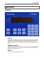
PW800 Users Manual Intercomp Co. 3839 County Road 116 Medina, MN 55340 U.S.A. (763)-476-2531 1-800-328-3336 Fax: 763-476-2613 www.intercompcompany.com Manual #: 700016-O Page 1 of 25 PW800, Users Rev O, January, 2008 SAFETY SUMMARY The following general safety precautions must be observed during all phases of operation, service, and repair of this scale. Failure to comply with these precautions or with specific warnings elsewhere in this manual violates safety standards of design, manufacture, and intended use of the scale. Intercomp assumes no liability for the customer's failure to comply with these requirements. DO NOT OPERATE IN AN EXPLOSIVE ATMOSPHERE. Do not operate the scale in a closed area saturated with flammable gases or fumes. Operation of any electrical instrument in such an environment constitutes a definite safety hazard. DO NOT SUBSTITUTE PARTS OR MODIFY SCALE. Because of the danger of introducing hazards, do not substitute parts or perform any unauthorized modifications of the scale. WARRANTY INTERCOMP COMPANY warrants the PW800 scale which this document accompanies to be free of defects in materials and workmanship, and to operate according to design specifications for a period of one (1) year after receipt by the original purchaser. After authorized return to the company at the purchaser's expense, the company shall evaluate any returned equipment under warranty claim, and shall make such repairs or replacements as may be judged necessary, in as expeditious a manner as possible. IN THE EVENT that the company determines the claim to be made as a result of improper use, abuse, modification, shipping damage, or other factors beyond the reasonable control of the company, the company will advise the purchaser of the estimated repair costs. The company makes no warranty other than that contained in this statement. No agent other than an executive officer of Intercomp Corporation is empowered to modify in any manner this statement of warranty. COMPLIANCE WITH FCC RULES Please note that this equipment generates, uses, and can radiate radio frequency energy. If this equipment is not installed and used in accordance with the support manual, you are warned that it may cause interference to radio communications. This unit has been tested and has been found to comply with the limits for a Class A computing device pursuant to subpart J of part 15 of FCC Rules. These rules are designed to provide reasonable protection against interference when equipment is operated in a commercial environment. However, if this unit is operated in a residential area, it is likely to cause interference and under these circumstances the user will be required to take whatever measures are necessary to eliminate the interference at his own expense. 2 PW800, Users Rev O, January, 2008 Table of Contents INTRODUCTION .......................................................................................................................................................4 SPECIFICATIONS .........................................................................................................................................................4 Controls................................................................................................................................................................4 Electrical..............................................................................................................................................................4 Performance.........................................................................................................................................................4 Environmental......................................................................................................................................................4 Physical................................................................................................................................................................4 PARTS AND OPTIONAL EQUIPMENT ............................................................................................................................5 OPERATIONS.............................................................................................................................................................6 CONTROLS .................................................................................................................................................................6 ON/OFF ...............................................................................................................................................................6 NUMERIC KEYPAD............................................................................................................................................6 ENTER .................................................................................................................................................................6 CLEAR .................................................................................................................................................................7 ZERO....................................................................................................................................................................7 AZT (Auto Zero Tracking) ............................................................................................................................................... 7 NET/GROSS .........................................................................................................................................................7 TARE ....................................................................................................................................................................7 PRESET TARE .....................................................................................................................................................8 UNITS/PIECES ....................................................................................................................................................8 SAMPLE...............................................................................................................................................................8 APW .....................................................................................................................................................................8 TOTAL..................................................................................................................................................................9 PEAK HOLD........................................................................................................................................................9 PRINT ..................................................................................................................................................................9 POWER/BATTERIES ..................................................................................................................................................10 CALIBRATION.........................................................................................................................................................11 HOW TO TEST CALIBRATION ....................................................................................................................................11 HOW TO CALIBRATE THE PW800 ............................................................................................................................12 Weight calibration..............................................................................................................................................16 ERROR MESSAGES ................................................................................................................................................17 TROUBLESHOOTING ............................................................................................................................................18 PARTS AND ACCESSORIES..................................................................................................................................20 PRINTER OUTPUT..................................................................................................................................................22 PRINTER TICKET (DEMAND).....................................................................................................................................22 SCOREBOARD (CONTINUOUS) ..................................................................................................................................23 HOW TO REACH INTERCOMP SERVICE.........................................................................................................25 "This document is the property of Intercomp Co. It contains material and information that is confidential and protected under federal and/or state trade secret, unfair competition, and copyright law. Any reproduction, use or disclosure without written permission from Intercomp Co. is prohibited". 3 PW800, Users Rev O, January, 2008 Introduction This manual contains specifications, operation instructions, and calibration instructions for Intercomp's model PW800 pallet scale. Troubleshooting tips and a parts and accessories listing are also included. Specifications Controls Display: Indicators: Switches: Light. 0.8” 5 digit LED (Optional: 5 digit, 1.0 inch LCD) On-screen lb, kg, pieces, gross, net, total, and peak. ON/OFF, ZERO, NET/GROSS, MODE, TARE, UNITS/PIECES, TOTAL, SCALE SELECT, PRESET TARE, SAMPLE, APW, PEAK HOLD, OVER, UNDER, I.D.#, SET POINT 1, SET POINT 2, PRINT, ENTER, CLEAR, numeric 10-key. Automatic in low light Electrical Batteries: Battery life: Charge Time: Charger Voltage: Charger Current: Charger/Power Supply: Low Battery Shut Off: Auto Shut Off: Sleep mode: Serial Input/Output: 9 Nickel-Cadmium D cells or Alkaline. Up to 75 hours with alkaline batteries. Up to 25 hours with Ni-Cad cells. (LED Display) 16 Hours 12 to 20 V AC/DC 250 ma 110 VAC or 220 VAC. Unit automatically shuts off if batteries are low. Shuts off after adjustable time (up to 120 min) without use or motion. Low power mode after adjustable time (up to 120 min) without use or motion. RS232 standard. RS485, and TTL optional Performance Accuracy: ± 0.1% of applied load or ± display graduation, whichever is greater. Environmental Humidity: Temperature: 10 to 95% Non-Condensing. Operating: -10 C to +40 C. / +14 F to +104 F. Storage: -40 C to +75 C. / -40 F to +170 F Physical Dimensions: Weight: (Standard Forks) 48" L x 28" W x 2.9"H / 1219 mm x 711 mm x 74 mm 275 lbs/125 kgs 4 PW800, Users Rev O, January, 2008 Parts and Optional Equipment LCD Display (100923) Optional LCD (liquid crystal display) display instead of the standard LED (light emitting diode display). RS232C Serial data output (100922) An RS232 output allows the user to connect the PW800 to a printer or computer. Battery operated tape printer (100921) Print ticket displays gross, net, tare, and total weights; and total count. Must have the RS232 Serial data output option. See “Printer Output” section for more information. 120V Charger (100919) Batteries, circuit, and harness included. Rechargeable Ni-Cad battery pack (9 D-cells) with 120V external charger. Standard power uses 9 disposable alkaline dry cells. 220V Charger (100920) Batteries, circuit, and harness included. Rechargeable Ni-Cad battery pack (9 D-cells) with 220V external charger. Standard power uses 9 disposable alkaline dry cells. Drum Brake Needed for parking on slopes. Stainless steel pallet truck Corrosion free. This option is often used to comply to FDA requirements (instead of using galvanized). Galvanized pallet truck Corrosion free Custom fork length Custom length and width to fit your pallet dimensions or other applications. Brass wheels Used in environments where sparks are a concern. 5 PW800, Users Rev O, January, 2008 Operations Controls ON/OFF Press and hold this button 1 second to turn the scale on and off. The scale tests itself; when this test is completed successfully the system begins weighing. The product I.D. and software version number are display for a couple seconds upon power up. The number on the left is the product ID and the number on the right is the software version number. NUMERIC KEYPAD Many operations require the operator to enter a number. The 10-key numeric keypad is used to enter numbers. These keys also have specific functions (as labeled) when the scale is in normal weighing mode. ENTER Press the ENTER key after entering a number 6 PW800, Users Rev O, January, 2008 CLEAR If you want to clear the number displayed (while in the process of entering a number), press the CLEAR key. ZERO Tells the scale to display zero weight. This button is used any time the scale shows a non-zero value with no weight on the load cell. If you press ZERO with weight on the load cell, that weight becomes the zero condition for the scale. This can be useful to cancel the weight of any weighing fixtures, such as barrels or boxes. When this weight is removed, a negative number is displayed until the system is re-zeroed. The 'zero' command will be delayed any time a change in weight is detected. While the scale is stabilizing, the display will show “ -0- “. If there is continuous motion for about 15 seconds, the zero command will be rejected and the scale will return to normal weighing. AZT (Auto Zero Tracking) This system contains a feature called Auto Zero Tracking (AZT), which corrects slight zero changes during normal operation. If small weights are added while the display is at or near zero, the scale may zero them off. NET/GROSS Toggles the readout between net weight and gross weight. Net weight applies only when there is a tare set. The indicator on the left side shows if the PW800 is displaying gross or net weight. Net = Gross – Tare Notes: The weight will always be net when in pieces unit. If Net/Gross key is pressed when a total is set the error message “ E-2 “ will be displayed. You must clear the current total before toggling NET/GROSS. TARE Use this button to read a tare weight into memory. This tare weight will be subtracted from the gross weight, giving you the net weight. This is useful for canceling the weight of a container used in weighing. A segment in the lower left corner of the display shows that the net weight is being calculated. You may press the TARE SET/DISPLAY button to show the tare weight anytime the scale is in net mode; the tare weight will show while you press the button. To clear the tare press the TARE and CLEAR keys simultaneously. Tare does not function in pieces unit. Notes: The 'tare' command will be delayed any time a change in weight is detected. If there is continuous motion for more than 20 or 30 seconds, the tare command will be rejected and the scale will return to normal weighing. Tare does not function in pieces unit. 7 PW800, Users Rev O, January, 2008 PRESET TARE Pressing the PRESET TARE key will bring up a screen that allows the user to enter a tare value. Enter the tare value using the numeric keypad and then press ENTER. To clear the tare press the TARE and CLEAR keys simultaneously. Notes: Tare does not function in pieces unit. UNITS/PIECES Toggles the weighing system between pound (English), and kilogram (SI metric), and ‘pieces’ (quantity of items) units of measure. When you press this switch, the system switches to the nearest comparable value in the selected system. The current unit of measure is shown by indicator segments on the left side of the main display. Note: An error message “ E-2 “ will be displayed if the UNIT/PIECES key is pressed when there is a total saved. You must clear the current total before toggling NET/GROSS. SAMPLE Sample is used to so you can view the weight in pieces. Place a number of items on the scale. A good rule of thumb is to place 3%-5% of the total number of pieces you intend to weigh. With a known quantity of items on the scale press the SAMPLE key. Enter the number of items on the scale. The sample measurement is saved in the scale’s memory. The scale will switch to the unit ‘pieces’ and display the number of pieces on the scale. To clear the sample measurement saved in memory, press the SAMPLE and CLEAR keys simultaneously. APW APW is the abbreviation of Average Piece Weight. Press the APW key. Enter the average weight of one piece. The scale switches to ‘pieces’ unit and displays the number of pieces on the scale. To clear the APW press the APW and CLEAR keys simultaneously. If you need to enter piece weights less than 1 lb or 1 kg, see the APW decimal position section in ‘Calibration’. This can setup your PW800 to record APW’s by tenths (1 decimal place) or by hundredths (2 decimal places). 8 PW800, Users Rev O, January, 2008 TOTAL This function is used to record an accumulated total. When you press the TOTAL key, the weight that is to be added to the accumulated total will blink for about 5 seconds. To add this to the total, press the TOTAL key again before the value stops blinking. The accumulated total will be displayed for about 2 seconds and return to the previous weighing mode. If you just want to view the total, press and hold the TOTAL key for about 3 seconds. The weight will be displayed until you release the key. To clear the accumulated total, press the TOTAL and CLEAR keys simultaneously. Note: You must clear the total before switching units or toggling NET/GROSS. PEAK HOLD The peak hold feature will remember the maximum weight applied. While in peak mode it will not display any weight less than the maximum weight. To turn on the peak mode press PEAK, to turn off the peak mode press PEAK again. The peak indicator will be blinking if in peak mode. To clear the current peak weight, press the ZERO key. Note: When you turn off the peak mode, the current peak weight will still be remembered internally. This will show up if you then turn the peak mode back on. Press ZERO while in peak mode (or turn the scale off) to clear the current peak weight. PRINT If the scale is configured to demand output, pressing this key will print a ticket. NOTE: The print ticket will be delayed any time a change in weight is detected. If there is continuous motion for more than 20 or 30 seconds, the print request will be rejected and the scale will return to normal weighing. Also see Serial Output section. SET POINT 1 This is an optional feature that allows for an external set point. When the specified weight (set point) is reached, a logic level high will be on the set point connection. Set points are used with some other device (e.g. alarm, relay) in conjunction to the PW800. To activate a set point, press the Set Point 1 (or Set Point 2) key. Enter the weight you want the set point to activate. SET POINT 2 Operates the same as Set Point 1. I.D. # User I.D. # is reserved for future use. MODE Reserved for future use. OVER Reserved for future use. 9 PW800, Users Rev O, January, 2008 SCALE SELECT Reserved for future use. UNDER Reserved for future use. Power/Batteries To change batteries: 1. Loosen the two "quarter-turn" connectors on the back of the control box. 2. Pull the cover back and change the cells, being careful to note battery orientation. 3. Replace the cover and tighten the quarter-turn connectors. Warning: If you have the optional charger, do not plug the charger in while there are standard ‘D’ cells inside. This could result in damage to the batteries and your scale. The typical recharge time for Ni-cad cells is 16 hours. The rechargeable batteries have a life span up to 1000 cycles. 10 PW800, Users Rev O, January, 2008 Calibration How to test Calibration This calibration procedure should be performed annually for normal operating conditions. If the scale is damaged, or service has been performed on the scale, use this calibration check. 1: Press the ON switch. 2: It is recommended that you allow the electronics to operate for three minutes after first turning power on. This allows the electronics to become stable for maximum accuracy during the calibration check. 3: Make sure no weight is on the load cell(s). Press the ZERO switch. The weight shown is zero. 4: Apply weights at various points within the load range and verify that the displayed weight is within +/- 0.1% of applied load. 5: If possible apply a weight of 105% of capacity to verify that the scale shows overload. 6: Verify the scale displays zero when the calibration weights are removed. 7: If there is a failure to meet any of the conditions above, please refer to the Calibration Procedure. 8: When all the conditions above are correct, the scale is operational. Calibration blocking switch The calibration of the scale is protected from accidental change by a shunt placed on a header on the circuit board. The cal header (labeled CAL/RUN”) is located opposite the display side at the top and middle of the circuit board. Calibration is set in the “calibration blocked” (shunt is on the RUN side of the header) mode at the factory. To enable calibration, move the shunt to the CAL side of the header. When you are done calibrating, return the switch to 'RUN' to protect against change. 11 PW800, Users Rev O, January, 2008 How to Calibrate the PW800 The following details the calibration procedure for the PW800 scale. There are eight parameters that can be set without moving the calibration blocking switch, followed by five more parameters and calibration that require the calibration blocking switch be in the 'CAL' position. Step ee-ee EE-00 EE-01 EE-02 EE-03 EE-04 EE-05 EE-06 Parameter Skip Sample Rate Sleep Display Time Auto-off Time Baud Rate Power up in KG Decimal point position for APW Serial Output Save information Note 0,1=EE-07 EE-07, LL-00 EE-07 2=LL-00 1 to 127 0 to 120; 0=off 0 to 255; 0=off 0 to 7 0=lb, 1=kg 0=none, 1=tenths, 2=hundreths 0=continuous, 1=on demand Default 0 8 20 120 0 0 0 1 Check for calibration blocking switch EE-07 ee-08 EE-09 EE-10 EE-11 EE-12 EE-13 LL-00 LL-01 LL-02 LL-03 AZT Zero Range Canadian Specifications Initial Zero Range Graduation Reserved Circuit Board ID # Save Zero read First weight Second weight Third weight Save 0=off,1=0.6,2=1,3=3 0=off,1=on 0=off,1=on 0=off,1=on 0 to 11 2 0 0 0 6 1 to 159 1 Enter capacity Enter first weight Enter second weight Enter third weight Start up 1. Remove the screws around the front panel. 2. Move the calibration blocking switch (located on back of the circuit board) to the 'CAL' position if you intend to calibrate. 3. Turn scale power ON. 4. Wait for scale to warm up (3 minutes from power on). 5. Using the UNITS button, set the scale to the appropriate units that you intend to calibrate with. 6. Press the NET/GROSS and MODE switches simultaneously. This enters you into the calibration routine. First seven parameters 7. The scale shows “EE-EE EE-EE”. EE-EE Press the NET/GROSS and MODE keys. To skip to “EE-07 EE-07” LL-00” EE-07 enter a ‘1’. To skip to “LL-00 LL-00 enter ‘2’. No skips will occur with an entry of ‘0’. 12 PW800, Users Rev O, January, 2008 8. The scale shows “EE-00 EE-00”. EE-00 Press the NET/GROSS and MODE keys. Enter the sample rate (1 to 127). The sample rate is the number of past readings that are averaged together to make a reading. 9. The scale shows “EE-01 EE-01”. EE-01 Press the NET/GROSS and MODE keys. Enter the sleep mode time (the number represents minutes). The sleep mode time is how long the scale's display will remain ON without any activity (a key being pressed or a change in weight). An entry of 0 turns the sleep mode feature OFF. The sleep mode is designed to conserve battery life on scales with a LED display. 10. The scale shows “EE-02 EE-02”. EE-02 Press the NET/GROSS and MODE keys. Enter the auto off time (the number represents minutes). The auto off time is how long the scale will remain ON without any activity (a key being pressed or a change in weight). An entry of 0 turns the auto off feature OFF (The scale would remain on until turned off). 11. The scale shows “EE-03 EE-03”. EE-03 Press the NET/GROSS and MODE keys. Enter the baud rate of the serial output (0 to 7). Setting 0 1 2 3 4 5 6 7 8 9 Baud Rate 9600 4800 2400 1200 600 300 150 75 19.2K 38.4K 12. The scale shows “EE-04 EE-04”. EE-04 Press the NET/GROSS and MODE keys. Enter what unit of measure the scale should turn ON in; pounds or kilograms (0 to 1). Setting 0 1 Units to turn ON in pounds (lb) kilograms (kg) 13. The scale shows “EE-05 EE-05”. EE-05 Press the NET/GROSS and MODE keys. Enter the desired APW decimal position. See the section on APW for details. Setting 0 1 2 APW decimal position no decimal 1 decimal place 2 decimal places 13 PW800, Users Rev O, January, 2008 14. The scale shows “EE-06 EE-06”. EE-06 Press the NET/GROSS and MODE keys. Enter demand versus continuous on the optional serial output. See Serial Out section Setting 0 1 Type Continuous Demand Check for calibration blocking switch. At this point the scale saves any changes that have been made. A check is than made to see whether or not the calibration blocking switch is enabled (CAL). If enabled the calibration procedure is continued; if disabled (RUN) the scale returns to normal weighing. Last seven parameters. 15. The scale shows “EE-07 EE-07”. EE-07 Press the NET/GROSS and MODE keys. Enter the AZT size (0 to 3). The AZT size is the number of graduations the auto zero tracking can remove. Setting 0 1 2 3 AZT size Off 0.6 1 3 16. The scale shows “EE-08 EE-08”. EE-08 Press the NET/GROSS and MODE keys. Enter whether the zero range is on or off (0 to 1). If the zero range is ON the zero may move no more than 5% away from the original zero obtained at calibration. Setting 0 1 Zero range Off On 17. The scale shows “EE-09 EE-09”. EE-09 Press the NET/GROSS and MODE keys. The scale shows the current Canadian specification selection. Use the following table to select the Canadian specifications setting. When Canadian specifications are set (1): EE-08, EE-08 EE-09, EE-09 and EE-11 have no meaning. Setting 0 1 Canadian Specification Off On A '0' setting implies normal operation: 1: AZT size is determined by the setting of EE-10. EE-10 2: Zero operates over full range allowed by EE-11. EE-11 3: The over-capacity point is determined by the setting of EE-13. EE-13 A '1' setting implies Canadian specifications are used. 1: The AZT size fixed at 0.6d regardless of EE-08 setting. 14 PW800, Users Rev O, January, 2008 2: The IZSM (initial zero setting mechanism on power up) must be within +/- 10% of the zero obtained at calibration. 3: The push-button zero and AZSM can only operate within +/- 2% of the IZSM. 4: The over-capacity point is 103% of capacity above the IZSM. 18. The scale shows “EE-10 EE-10”. EE-10 Press the NET/GROSS and MODE keys. The scale shows the current 'Initial zero range' setting. Use the following table to select the 'Initial zero range' setting: Setting 0 1 Initial zero range Off On A '0' setting implies: The initial zero setting mechanism (IZSM) will work over the entire range of the scale capacity and the over-capacity point is 103% above the zero obtained at calibration. A '1' setting implies: The IZSM must be within +/- 10% of the zero obtained at calibration and the over-capacity point is 103% above the IZSM. 19. The scale shows “EE-11 EE-11”. EE-11 Press the NET/GROSS and MODE keys. The scale shows the current graduation selection. Use the following table to select a graduation value. Settings 0 1 2 3 4 5 6 7 8 9 10 11 Count by in lb 100 50 20 10 5 2 1 0.5 0.2 0.1 0.05 0.02 Count by in kg 50 20 10 5 2 1 0.5 0.2 0.1 0.05 0.02 0.01 20. The display shows “EE-12 EE-12”. EE-12 This parameter is reserved for future use. Press NET/GROSS and MODE keys together twice to continue. 21. The scale shows “EE-13 EE-13”. EE-13 Press the NET/GROSS and MODE keys. The display shows the current circuit board ID#. This is used in multi scale applications. The circuit board ID is used for identification. 15 PW800, Users Rev O, January, 2008 Save The display shows “LL-00 LL-00”. LL-00 At this point the scale saves any changes that have been made. This allows changes to be made to EE-07 through EE-13 without having to do a complete calibration. The scale can be turned off and any changes so far will be saved. Weight calibration. The scale has a three point calibration feature which reduces the effects on non-linearity in the load cells. This requires that you place three weights on the load cell(s) during calibration. The first weight must be greater than zero, the second greater than the first, and the final weight somewhere between the second and the capacity. 22. The scale shows “LL-00 LL-00”. LL-00 With no weight on the load cell(s) press the NET/GROSS and MODE keys. Then enter your intended weight capacity (then press both the NET/GROSS and MODE keys). 23. The scale shows “LL-01 LL-01”. LL-01 Apply the first weight. Press the NET/GROSS and MODE keys. Then enter the exact value of the applied weight (then press both the NET/GROSS and MODE keys). 24. The scale shows “LL-02 LL-02”. LL-02 Apply the second weight. Press both the NET/GROSS and MODE keys. Then enter the exact value of the applied weight (then press both the NET/GROSS and MODE keys). 25. The scale shows “LL-03 LL-03”. LL-03 Apply the third weight. Press both the NET/GROSS and MODE keys. Then enter the exact value of the applied weight (then press both the NET/GROSS and MODE keys). Finish The new calibration information is saved. 26. Reset the calibration enable switch to its original position (RUN). This prevents accidental entry in the calibration routine. 27. Check the calibration with the procedure already discussed in this manual. 16 PW800, Users Rev O, January, 2008 Error Messages [Minus signs cycle across the display]: The PW800 has entered sleep mode. Press any key or change the weight to return to normal weighing. NOTE: a pressed key here will perform its designated function as well as exit the scale from sleep mode. [Minus signs fill display]: The PW800 is waiting for a stable reading to continue. DISE LB OE EEPE OL E-0 E-2 Display error, the scale is unable to display the number completely. If no weight on the scale, press zero to return the weight reading to zero. Low batteries. This message blinks, and if ignored too long the unit will shut itself off. The scale is over capacity or outside the A/D converter range. Reduce the load to the scale. If the PW800 continues to display “OE OE”, OE the problem could be a bad load cell, bad load cell wiring, or a bad chip on the AD 20-bit board (U3, U4, U5, U6, VR2, VR4, or U11) EEPROM error, the scale has had it's calibration corrupted or destroyed; the scale will require calibration. Zero overload; the PW800 has attempted to zero a reading outside of its zerorange limit. This message can occur only when the 'Zero range' or 'Canadian specifications' is turned on. See EE-08, EE-08 EE-09 in the 'calibration' section. This message occurs if the scale is turned on with a load applied which is greater than ±10% of capacity. Return the scale's load to zero. This only occurs when 'Canadian specifications' or 'Initial zero range' is turned on. See EE-09 and EE-10 in the 'calibration' section. This error will be display if there is a saved total and the user tries to switch units or press the NET/GROSS key. Clear the total by pressing TOTAL and CLEAR. 17 PW800, Users Rev O, January, 2008 TroubleShooting Warning: Changing some parts on the circuit board may cause a large change in calibration while others may or may not change the calibration, depending on the nature of the problem. The reference designators for the IC chips are on the “A/D 20-BIT” board unless indicated otherwise. Problem: no power, nothing on display Fix: If nothing can be seen on the display, there probably is no power reaching the scale circuitry. Possible causes: bad or shorted battery pack, bad switch circuit, bad voltage regulator, or bad keypad. Power might be reaching the unit, but the power supply might be shorted by a component or PCB trace in the power supply circuitry. Problem: random display (display usually reads “8 8.8 8. 8.”) Fix: Check crystal (Y1). If the micro-controller is not receiving the correct or any oscillation, the microprocessor is not able to function properly. Other possibilities could be bad microprocessor (U1) or display driver (U1 & U2 on “GPI DISPLAY” board) circuitry not functioning. Problem: low battery indicator won’t turn off (display blinks “LB LB”) LB Fix: The display will be blinking “LB LB”. LB Check to make sure battery power is not too low. Look at the cells and charger circuit for these problems. If that is not the cause, the display driver ( U1 & U2 on the GPI display board) or low voltage circuitry could be bad. Problem: rechargeable battery life has decreased Fix: The rechargeable batteries provided by Intercomp are high quality, high capacity NiCad. However, all Ni-Cad batteries can exhibit some “memory” effects if they are repeatedly discharged to a certain point before recharging. If your observed battery life has decreased significantly from its initial performance, you may want to try this batteryconditioning sequence: Fully discharge the batteries by running the PW800 until the display blinks “LB LB” LB (low battery) and keep the unit powered until the batteries are fully discharged. Following this, recharge the battery completely (typical charge time is 16 hours). This discharge/recharge cycle may need to be repeated. If this does not help, you may need to replace the Ni-Cad batteries. Problem: scale shuts off by itself Fix: Check the battery holder terminals. They may be bent and not making solid contact. If the scale turns off immediately after you take your finger off the button, there may be defective power circuitry or a bad keypad. 18 PW800, Users Rev O, January, 2008 Problem: scale “locks up” Fix: The microprocessor (U1) may need to be replaced. The microprocessor support circuitry could also be bad. Problem: weights jump or drift Fix: Try increasing the sample rate as described in the calibration section (pg. 13). If this does not help, the problem could be a bad load cell, defective amplifier (U5), bad A/D chip (U6), or contamination on the circuit board. Problem: printer doesn’t work Fix: Check the cable for bad connections. Check the printer for power. If the PW800 has sufficient power, the problem is probably the power supply board for the printer (there is separate circuit board for the printer power supply). Check the voltage regulator and the other components. 19 PW800, Users Rev O, January, 2008 Parts and Accessories Control Box: Item # 1 2 3 4 5 6 7 8 9 10 11 12 QTY 1 1 1 1 1 1 1 1 1 1 1 1 Part # 502326-A 000079 550285 803016 000096-F 000092 501499 250174 250087 803017 220122 or 220029 Description control box summing board battery holder assembly battery cover optional: power supply for printer A/D circuit board Display circuit board control box lid red window keypad printer cover optional: 25-pin D sub connector (or 9-pin connector) 20 PW800, Users Rev O, January, 2008 Pallet Truck Kit: #800301 21 PW800, Users Rev O, January, 2008 Printer Output The PW800 can be set to output either a printer ticket (demand) or scoreboard (continuous). The default is a printer ticket, but this can be changed in the 'calibration' section EE-06. EE-06 Printer Ticket (demand) The printer ticket output is an externally available signal designed to drive a printer or a computer's RS-232 input. Transmitted data: N***xxxxx*[unit]<cr><lf> G***xxxxx*[unit<cr><lf> T***xxxxx*[unit]<cr><lf> <cr><lf> TOT***xxxxx*[unit]<cr><lf> PIECES**xxxxx<cr><lf> The items have the following meanings: Item G N T xxxxxxx [unit] * <cr> <lf> Meaning Gross weight Net weight Tare data ASCII value of lb, kg, or pcs space carriage return linefeed 22 ASCII Hex 47 4E 54 ASCII Decimal 71 78 84 20 0D 0A 32 13 10 PW800, Users Rev O, January, 2008 Scoreboard (continuous) The scoreboard output is an externally available signal designed to drive a numeric overhead display board or a computer's RS-232 input. The transmitted signal has the following characteristics: Fixed 8 data bits, no parity, 1 stop bit. Baud rate is configurable under EE-3, see calibration section. Transmitted data: xxxxxx<cr><lf> The xxxxxx field will vary in length depending on the length of the number and could contain a decimal point and/or a minus sign. This represents the NET, GROSS, or PEAK weight, whichever is currently shown on the PW800 display. The data is repeatedly sent out about once a second. If your PW800 is specially fitted with a RS-232 output connector, the pin-out is as follows: Pin 2 = TXD, and pin 7 = GND. See the following pages for some example connections. The scoreboard is designed to work with Intercomp's S400 (4 inch) and SA2000 (2 inch) scoreboards. The following describes how to configure the S400 or SA2000 to work with the scoreboard output. The above diagram is the S400 switch pack layout, The SA2000 has pack C below B. The switch is to the right for on and to the left for off. 23 PW800, Users Rev O, January, 2008 Switch # 1 2 3 4 5 6 7 8 Pack A OFF ON ON ON ON OFF OFF ON Pack B OFF ON OFF OFF ON ON ON ON Pack C See Below " " " ON ON OFF OFF The above switches should be set on switch packs A, B, and C. Pack C, SW 1 to 4: Baud Rate 9600 4800 2400 1200 600 300 150 75 C-1 ON OFF ON OFF ON OFF ON OFF C-2 ON ON ON OFF OFF ON OFF OFF C-3 ON ON OFF ON OFF OFF OFF ON The connection to an Intercomp S400 display is: PW800 2 (TXD) 7 (GND) S400 2 (RXD) 7 (GND) The connection to an Intercomp SA2000 display is: PW800 2 (TXD) 7 (GND) SA2000 3 (RXD) 7 (GND) C-4 OFF OFF OFF OFF ON OFF OFF ON The connection to a 9-pin PC communication port is: PW800 PC 9-pin 2 (TXD) 2 (RXD) 7 (GND) 5 (GND) Note: For some setups it may be necessary to jump pins [6, 1, and 4] together, and pins [7 and 8] together on the PC port connector. The connection to a 25-pin PC communication port is: PW800 2 (TXD) 7 (GND) PC 25-pin 3 (RXD) 7 (GND) Note: For some setups it may be necessary to jump pins [6, 8, and 20] together, and pins [4 and 5] together on the PC port connector. 24 PW800, Users Rev O, January, 2008 How to reach Intercomp Service Things to know: 1. When did you purchase your scale? 2. What is your serial number? 3. Whom did you purchase the scale through? For Intercomp Service call or fax: FAX# (763) 476-2613 (763) 476-2531 1-800-328-3336 or fill out Service Support Form: www.intercompcompany.com Copyright Intercomp Company 2008 All rights reserved 25