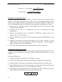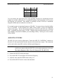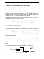
1
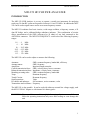
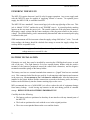
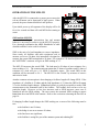
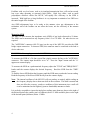
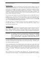
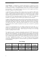
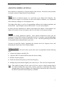
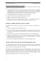
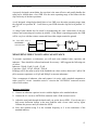
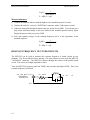
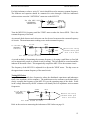
TABLE OF CONTENTS
Introduction................................................................................................................. 1
Powering The MFJ-259 .............................................................................................. 2
Battery Installation...................................................................................................... 2
Operation Of The MFJ-259 ........................................................................................ 3
SWR and the MFJ-259 ................................................................................... 3
Measuring SWR.............................................................................................. 4
Resistance Meter............................................................................................. 5
Frequency Counter.......................................................................................... 5
Adjusting Simple Antennas ........................................................................................ 7
Dipoles ............................................................................................................ 7
Verticals .......................................................................................................... 7
Tuning an Antenna.......................................................................................... 7
Measuring the Feedpoint Resistance of Antennas .......................................... 8
Finding a Short Circuit in Coax Cables ...................................................................... 8
Testing and Tuning Stubs and Transmission Lines .................................................... 8
Velocity Factor of Transmission Lines ........................................................... 9
Impedance of Transmission Lines .................................................................. 10
Estimating transmission line loss.................................................................... 10
Adjusting Tuners......................................................................................................... 11
Adjusting Amplifier Matching Networks ................................................................... 12
Testing RF Transformers ............................................................................................ 12
Testing Baluns ................................................................................................ 12
Measuring Inductance and Capacitance...................................................................... 13
Measure capacitance. ...................................................................................... 13
Measure inductance. ....................................................................................... 14
Resonant Frequency of tuned circuits ......................................................................... 14
Testing RF Chokes.......................................................................................... 15
Technical Assistance................................................................................................... 16
MFJ-259 Parts List...................................................................................................... 16
MFJ-259 Instruction Manual
HF/VHF SWR Analyzer
MFJ-259 HF/VHF SWR ANALYZER
INTRODUCTION
The MFJ-259 SWR Analyzer is an easy to operate, versatile test instrument for analyzing
nearly any 50 ohm RF system on frequencies between 1.8 and 170 MHz. In addition the MFJ259 can be used as signal source and as an accurate frequency counter.
The MFJ-259 combines four basic circuits; a wide range oscillator, a frequency counter, a 50
ohm RF bridge, and a calibrated bridge unbalance indicator. This combination of circuits
allows measurement of the SWR (referenced to 50 ohms) of any load connected to the
ANTENNA connector. The MFJ-259 FREQUENCY switch selects the following frequency
ranges:
1.8
4
10
26.2
62.5
113
-
4
10
26.2
62.5
113
170
MHz
MHz
MHz
MHz
MHz
MHz
The MFJ-259 can be used to adjust or measure the following:
Antennas:
Antenna tuners:
Amplifiers:
Coaxial transmission lines:
Balanced transmission lines:
Matching or tuning stubs:
Traps:
Tuned Circuits:
Small capacitors:
RF chokes and inductors:
Transmitters and oscillators:
SWR, resonant frequency, bandwidth, efficiency
SWR, frequency
Input and output networks
SWR, velocity factor, losses, resonance
Impedance, velocity factor, resonance
SWR, resonant frequency, bandwidth
Resonant frequency
Resonant frequency
Value
Self resonance, series resonance, value
Frequency
The MFJ-259 is also portable. It can be used with either an external low voltage supply, such
the MFJ-1312B AC adapter or with internal AA battery packs.
WARNING: Please read this manual thoroughly before using this instrument. Failure to
follow the operating instructions may cause false readings or even damage this
unit.
1
MFJ-259 Instruction Manual
HF/VHF SWR Analyzer
POWERING THE MFJ-259
The MFJ-259 requires between 8 and 18 volts for proper operation. Any power supply used
with the MFJ-259 must be capable of supplying 200mA of current. An optional power
supply, the MFJ-1312B, is available from MFJ.
The MFJ-259 has a standard 2.1 mm coaxial type jack on the top right edge of the case. This
jack is labeled "12VDC" and has the word "POWER" near it. A pictorial polarity marking
appears on the case near the power jack. The outside conductor of the plug must connect to
the negative supply voltage and the center conductor of the plug must connect to the positive
voltage. The internal battery pack is automatically disconnected when an external power plug
is inserted in this jack.
SWR measurement will be inaccurate when the supply voltage falls below 7 volts. To avoid
false readings, the battery should be checked after storage to ensure the supply voltage does
not drop below acceptable levels.
WARNING: Never apply unfiltered AC or incorrectly polarized DC to this jack. Peak
voltage must never exceed 18 volts.
BATTERY INSTALLATION
If batteries are used, they must be installed by removing the 8 Phillips head screws on each
side of the case. The eight batteries fit in two separate battery holders with the positive
terminal of the batteries positioned toward the round fixed connection, and the negative
terminals toward the springs of the battery holder.
The battery case has two external terminals that connect to a "pigtail" that has two terminals
on it. This connector looks like the type used for 9 volt transistor radio batteries and connects
in the same way. Do not attempt to use 9 volt batteries with this unit. After the batteries are
installed in the plastic holders and the connections are made to the battery packs, the battery
holders can be slid directly into the chrome retaining clips on the cover.
MFJ recommends the use of ALKALINE AA cells to reduce the risk of equipment damage
from battery leakage. Avoid leaving any batteries in this unit during periods of extended
storage. REMOVE WEAK BATTERIES IMMEDIATELY!
Carefully check the following:
• The battery packs are positioned so that they do not interfere with any internal parts of
the MFJ-259.
• The leads are positioned to reach with the cover in the original position.
• The wires are not pinched between the cover and the chassis.
2
MFJ-259 Instruction Manual
HF/VHF SWR Analyzer
OPERATION OF THE MFJ-259
After the MFJ-259 is connected to a proper power source the
red on-off button can be depressed to apply power. When
pressed, the power button should lock into position.
Upon initial power up all segments of the display will be lit
for a few seconds and then will read MFJ before starting to
count.
20
30
40
50
100
500
10
0
SWR
Resistance
(ohms)
SWR and the MFJ-259
Some understanding of transmission line and antenna
behavior is necessary in order to use the MFJ-259 properly.
For a thorough explanation the ARRL Handbooks or other
detailed textbooks can be used for reference.
SWR is the ratio of a load impedance to source impedance.
Since nearly all feedlines and radio equipment used in
amateur service are 50 ohms, this instrument is designed to
measure the system SWR normalized to 50 ohms. For example a 150 ohm load placed across
the "ANTENNA" connector will give an SWR reading of 3:1 .
The MFJ-259 measures the actual SWR. The load must be 50 ohms of pure resistance for a
meter reading of 1:1 . The common misconception that 25 ohms of reactance and 25 ohms of
resistance in a load will give a 1:1 SWR is absolutely untrue. The actual SWR in this
condition will be measured as 2.6:1 . The MFJ-259 is not "fooled" by mixtures of reactive
and resistive loads.
Another common misconception is that changing a feedlines length will change SWR. If the
impedance of a feedline is 50 ohms and the load impedance is 25 ohms the SWR will remain
2:1 as the feedline length changes. If line loss is low it is perfectly acceptable to make SWR
measurements at the transmitter end of the feedline. The feedline does not have to be any
particular length. However, as line loss increases, and as SWR increases, more error is
introduced into the SWR reading. The error causes the measured SWR reading to appear
better than the actual SWR at the antenna. Refer to the section on estimating the line loss on
page 10.
If changing feedline length changes the SWR reading one or more of the following must be
true:
• the feedline is not 50 ohms,
• the bridge is not set to measure 50 ohms,
• the line losses are significant,
• the feedline is acting like part of the antenna system and radiating RF.
3
MFJ-259 Instruction Manual
HF/VHF SWR Analyzer
Feedlines with very low losses, such as air insulated transmission lines, will not have much
loss even when operating at extremely high SWRs. High loss cables, such as small
polyethylene dielectric cables like RG-58, will rapidly lose efficiency as the SWR is
increased. With high loss or long feedlines it is very important to maintain a low SWR over
the entire length of the feedline.
Any SWR adjustments have to be made at the antenna, since any adjustments at the
transmitter end of the feedline can not affect the losses, nor the efficiency of the antenna
system.
Measuring SWR
The MFJ-259 will measure the impedance ratio (SWR) of any load referenced to 50 ohms.
The SWR can be measured on any frequency from 1.8 to 170 MHz. No other devices are
required.
The "ANTENNA" connector (SO-239 type) on the top of the MFJ-259 provides the SWR
bridge output connection. To measure SWR, this connector must be connected to the load or
device under test.
WARNING: Never apply power to the "ANTENNA" connector.
To measure the SWR of a 50 ohm coaxial line simply connect the line to the "ANTENNA"
connector. The counter input should be set to "A". Press the "Input" button until the "A"
appears on counter display.
To measure the SWR on a predetermined frequency adjust the "TUNE" and "FREQUENCY"
knobs until the counter displays the desired frequency. Read the SWR from the "SWR"
meter.
To find the lowest SWR adjust the frequency until the SWR meter reaches the lowest reading.
Read the frequency of the lowest SWR directly from the counter display.
Note: The internal oscillator of the MFJ-259 will not produce an entirely stable reading on
the frequency display due to short term drift in the oscillator. This drift is normal and
does not affect the accuracy, results or usefulness of this instrument since a null will
even be maintained on the highest Q (narrow bandwidth) antennas or loads.
It is perfectly acceptable to ignore decimal place readings more than two places to the right of
the decimal point in the counter (ten's of kilohertz) above 15 MHz and three places to the right
of the decimal point (kilohertz) below 15 MHz.
4
MFJ-259 Instruction Manual
HF/VHF SWR Analyzer
Resistance Meter
The resistance meter section of the MFJ-259 will provide resistance readings for the load
connected to the ANTENNA jack. The resistance meter will not give an accurate reading of a
reactive load. For example, if an antenna is resonant at 7.1 MHz and you attempt to measure
the resistance at 7.3 MHz, the resistance reading will not be accurate. To get an accurate
reading the TUNE knob should be adjusted until the lowest SWR reading is obtained. The
point of lowest SWR is generally the point of lowest reactance therefore the most accurate
point to read the antenna's pure resistance.
If the resistance meter indicates 50 ohms but the SWR meter indicates a high SWR the load is
probably reactive. Any time the resistance meter indicates a resistive ratio that disagrees with
the SWR reading the load is reactive. For example: If the resistance meter indicates 25 ohms (
a 2:1 SWR ) but the SWR meter indicates greater than 2:1, the load is reactive. For the SWR
to be 1:1, the load must be 50 ohms of pure resistance.
The SWR can not be 1:1 if reactance is present or the resistive component is not 50 ohms. If
the SWR meter indicates 1:1 but the resistance meter reads other than 50 ohms you are
experiencing an instrument error.
Frequency Counter
The frequency counter in the MFJ-259 will typically measure frequencies between a few hertz
and 200 MHz. At frequencies above 1 MHz, the frequency counter is sensitive to 600 mV.
Below 1 MHz, the counter is sensitive to TTL input voltage levels (5V peak to peak) with a
square wave input. The counter function is accurate to 1 part per million at room temperature.
WARNING: The frequency counter has a CMOS input device that can be easily damaged.
To avoid damage to the counter while using the "FREQUENCY COUNTER
INPUT" jack the user must observe the following precautions: NEVER
exceed 5 volts peak input. NEVER apply an input signal with the power
switch off.
To use the frequency counter turn the power "ON" and press the "INPUT" button on the top
panel until a "B" appears in the upper right corner of the counter display. The BNC jack is
now selected for input to the counter.
A basic operational check of the Channel B input on the counter can be made with a short
jumper wire. If a short jumper is placed from the center of the SO-239 connector to the center
of the BNC connector, the output of the MFJ-259 oscillator will be displayed on the counter
readout. The frequency displayed will be the same on both Channel A and Channel B, while
the jumper is in place. This check is useful when a reliable external RF source is not
available.
Input to Channel B may be provided in many different ways. The most common usage is
measuring the transmitter frequency. Never transmit directly into the MFJ-259, or it may be
5
MFJ-259 Instruction Manual
HF/VHF SWR Analyzer
severely damaged. A coupling loop is useful for directing RF at a reduced level into the
counter. A coil of wire, or even a straight piece of wire attached to the BNC connector may
be sufficient for operation. The length and number of turns will vary with the power supplied
by the transmitter. A weak signal will require a larger area of wire to supply a good level to
the counter, compared to a powerful transmitter.
A standard HT antenna, which has a BNC connector, may act as a conductor of RF into the
counter. An antenna with no loading coils is preferred to one which does. A 2 meter antenna
may not conduct enough energy to the counter if it is used on the HF bands. Antenna
attenuation can greatly reduce the RF level into the counter. The coupling antenna may have
to be much closer to the transmitting antenna if the transmit level is low. On a high power
transmitter, the coupling level may be useful for quite a distance from the transmitter.
Coupling of the RF signal into the counter may also be done by placing several turns of wire
around a coax feedline, and attaching it to the counter input. More turns will be needed for a
well-shielded cable than for a lossy cable. Hard-line is not usable since there is no leakage.
The leakage from the cable is usable under normal conditions for a low level counter input.
Experimentation will be needed to determine how many turns are needed for a particular
installation.
A loop of wire placed inside the case of a wattmeter, dummy load, low-pass filter, etc., is
another way to couple RF into the counter. The inductance of the loop will act as an antenna,
to direct low level RF into the counter. Almost any type of wire may act as a receiving
antenna for coupling RF into the counter.
The sample time period is selected by momentarily pressing the "GATE" button near the
upper left corner of the top panel. The counter displays the average frequency over the sample
time period. The red LED in the upper right corner of the front panel flashes when the count
cycle is complete and the display is updated.The blinking LED will speed up and/or slow
down with the changing of gate settings. At power up, the sample time period normalizes at
.01 seconds. Additional count periods of 0.1, 1.0, and 10 seconds can also be selected.
Connect the cable with the signal to be counted to the BNC type jack labeled "FREQUENCY
COUNTER INPUT".
Gate Settings
Gate Setting
1
2
3
4
6
Gate Time
10 mS
100 mS
1S
10 S
Measurement
Time
25 mS
130 mS
1S
10 S
Measurement
Resolution
100 Hz
10 Hz
1 Hz
0.1 Hz
Example
162.5500
162.55000
162.550000
162.5500000
MFJ-259 Instruction Manual
HF/VHF SWR Analyzer
ADJUSTING SIMPLE ANTENNAS
Most antennas are adjusted by varying the length of the elements. Most home made antennas
are simple verticals or dipoles that are easily adjusted.
Dipoles
Since a dipole is a balanced antenna, it is a good idea to put a balun at the feedpoint. The
balun can be as simple as several turns of coax several inches in diameter, or a complicated
affair with many windings on a ferromagnetic core.
The height of the dipole, as well as it's surroundings, influence the feedpoint impedance and
the line SWR. Typical heights result in SWRs below 1.5 to one on most dipoles.
In general, the only adjustment on a dipole is the length of the antenna. If the antenna is too
long it will resonate too low in frequency, and if it is too short it will resonate too high.
Verticals
Verticals are usually unbalanced antennas. Most antenna manufacturers down play the
importance of good radial systems with grounded verticals. If you have a good ground system
the SWR of a quarter wave vertical can be nearly 2 to one. The SWR generally gets BETTER
as the ground system, and performance, get worse.
Verticals are tuned like dipoles, lengthening the element moves the frequency lower, and
shortening the element moves the frequency higher.
Tuning an Antenna
Tuning basic antennas fed with 50 ohm coaxial cable can be accomplished with the following
steps:
1. Connect the feedline to the MFJ-259.
2. Adjust the MFJ-259 until the SWR reaches the lowest reading.
3. Read the frequency display.
4. Divide the measured frequency by the desired frequency.
5. Multiply the present antenna length by the result of step 4. This is the new length needed.
Note: This method of tuning will only work on full size vertical or dipole antennas that do
not employ loading coils, traps, stubs, resistors, capacitors or capacitance hats. These
antennas must be tuned according to the manufacturers instructions and re-tested with
the MFJ-259 until the desired frequency is obtained.
7
MFJ-259 Instruction Manual
HF/VHF SWR Analyzer
Measuring the Feedpoint Resistance of Antennas
The approximate feedpoint resistance of a low impedance (0-500 ohms) resonant HF or VHF
antenna or load can be measured with the MFJ-259.
1. Connect the MFJ-259 directly across the terminals of the unknown resistance. If the load
is unbalanced be sure that the ground is connected to the SO-239 "ANTENNA"
connectors outer shell. If the load is balanced it may be necessary to operate the MFJ-259
using internal battery power to allow the case of the unit to float above ground.
2. Set the band switch for the desired frequency measurement range.
3. Adjust the TUNE control until the SWR reads the lowest value.
4. Read the resistance directly from the resistance meter.
5. Double check the meter readings against each other. The SWR ratio should be
approximately equal to the ratio between the measured resistance and 50 ohms.
FINDING A SHORT CIRCUIT IN COAX CABLES
The MFJ-259 is very effective in locating a short circuit in coax cables. The method is as
follows:
1. Connect one end of the cable to the MFJ-259 input.
2. Turn on the MFJ-259 and start sweeping the frequency, starting at the low frequency end
of its range. Watch the RESISTANCE METER for a dip reading and record the frequency
for zero ohms.
3. Continue the sweep for the second dip, which should be at twice the first dip frequency.
4. Calculate the position of the short: Divide 492 by the first dip frequency (in MHz) and
multiply the result by the velocity factor of the coax cable being measured. The result
should be the location of the short (in feet).
5. You can check this number by shorting the other end and repeating the process.
TESTING AND TUNING STUBS AND TRANSMISSION LINES
The proper length of quarter and half wave stubs or transmission lines can be found with this
unit and a 50Ω carbon resistor. Accurate measurements can be made with any type of coaxial
or two wire line. The line does not have to be 50 ohms.
The stub to be tested should be attached with a 50Ω noninductive resistor in series to the
center conductor of the "ANTENNA" connector with a coaxial line. The shield should be
grounded to the connector shell. For two wire lines the 50Ω resistor connects in series
between the ground shell of the PL-259 and one conductor. The other conductor of the
balanced line connects directly to the center pin of the connector.
8
MFJ-259 Instruction Manual
HF/VHF SWR Analyzer
Coaxial lines can lay in a pile or coil on the floor, two wire lines must be suspended in a
straight line a few feet away from metallic objects or ground. The lines must be open
circuited at the far end for odd multiples of 1/4 wave stubs (i.e. 1/4, 3/4, 1-1/4, etc.) and short
circuited for half wave stub multiples ( like 1, 1-1/2, etc.)
Connect the PL-259 to the "ANTENNA" connector of the MFJ-259 and adjust the line or stub
by the following method. For critical stubs you may want to gradually trim the stub to
frequency.
1. Determine the desired frequency and theoretical length of the line or stub.
2. Cut the stub slightly longer than necessary.
3. Measure the frequency of the lowest SWR. It should be just below the desired frequency.
4. Divide the measured frequency by the desired frequency.
5. Multiply the result by the length of the stub. This is the necessary stub length.
6. Cut the stub to the calculated length and confirm that it has the lowest SWR near the
desired frequency.
Velocity Factor of Transmission Lines
The MFJ-259 can accurately determine the velocity factor of any impedance transmission line.
Measure the velocity factor with the following procedure:
1. Disconnect both ends of the transmission line and measure the physical length of the line
in feet.
2. Set up the line to measure 1/4 stubs as in the section on Testing and Tuning Stubs, page 8.
3. Find the lowest frequency across all the bands at which the lowest SWR occurs. The dip
should occur slightly below the 1/4 wavelength frequency.
4. Read the frequency from the frequency counter display. This is the 1/4 resonant
wavelength frequency of your transmission line. Note that you will get low SWR reading
at all odd multiples of 1/4 wavelength.
Example: On a 27 foot line the measured frequency was 7.3MHz.
5. Divide 246 by the measured frequency. This gives you the free space 1/4 wavelength in
feet.
Example: 246 divided by a dip frequency of 7.3 MHz is 33.7 feet, the free space 1/4
wavelength
6. Divide the physical measured length of the feedline in feet by the free space 1/4
wavelength calculated in number 5.
Example: 27 feet (physical length) divided by 33.7 feet (calculated length) equals .80 .
The velocity factor is .80 or 80%.
9
MFJ-259 Instruction Manual
HF/VHF SWR Analyzer
246
Low SWR frequency
Actual feedline length
Velocity Factor =
Free space 1/ 4 wavelength
Free space 1/ 4 wavelength =
Impedance of Transmission Lines
The impedance of transmission lines between 15 and 150 ohms can be measured with the
MFJ-259, a 250 ohm potentiometer, and an ohm meter. Lines of higher impedance can be
measured with a higher resistance potentiometer if a broad band transformer is used (see the
section on testing transformers) to transform the line impedance to approximately 50 ohms.
1. Measure the 1/4 wavelength frequency of the transmission line to be tested as in Testing
and Tuning Stubs on page 8.
2. Terminate the far end of the transmission line with a non-inductive 250 ohm
potentiometer.
3. Connect the transmission line to the MFJ-259 "ANTENNA" connector and set the
analyzer to the 1/4 wave frequency.
4. Observe the SWR as you vary the "TUNE" from end to end of the "FREQUENCY" range
selected.
5. Adjust the potentiometer until the SWR reading varies as little as possible, over the
"TUNE" range. Note that the value of the SWR is not important. Only the change in
SWR as the frequency is varied is important.
6. The value of the potentiometer will correspond closely to the line impedance.
Estimating Transmission Line Loss
The loss of 50 ohm feedlines (between 3 and 10 dB) can be measured with the MFJ-259. It is
a simple matter to find the loss at a known frequency and then estimate the loss at a lower
frequency.
To measure feedline loss:
1. Connect the feedline to the MFJ-259 "ANTENNA" connector.
2. The far end of the feedline is either left unconnected or terminated with a direct short.
3. Adjust the MFJ-259 frequency to the frequency desired and observe the "SWR" meter.
4. If the SWR is in the red area of the scale the loss is less than 3 dB. Increase the frequency
until the "SWR" meter reads 3:1. This is the 3dB loss frequency.
5. If the SWR on the operating frequency is in the black area of the "SWR" meter, pick the
closest SWR point and estimate the loss from the following chart.
SWR
10
LOSS
MFJ-259 Instruction Manual
HF/VHF SWR Analyzer
3.0 : 1
2.5 : 1
2.0 : 1
1.7 : 1
1.5 : 1
1.2 : 1
3.0 dB
3.6 dB
4.7 dB
5.8 dB
6.9 dB
10.3 dB
You can estimate the approximate loss at the operating frequency by remembering that the
feedline loss in dB is reduced by 70 % at half the frequency, and increased by 140 % at twice
the frequency you measured. This method is reasonably accurate if the loss is distributed
along the feedline and not confined to one bad area.
For example, assume an operating frequency of 28 MHz. You want to know what the feedline
loss is at 28 MHz. At that frequency the "SWR" meters needle is in the red uncalibrated
portion of the meter. Increase the measured frequency until the needle falls on a calibration
mark. At 60MHZ the meter reads 3:1 SWR. Using the chart you know that the loss is 3 dB.
Since 28MHz is about half of 60MHz, you can multiply 3dB by .7 which gives a loss of about
2dB at 28MHz.
ADJUSTING TUNERS
The MFJ-259 can be used to adjust tuners. Connect the MFJ-259 "ANTENNA" connector to
the tuner's 50 ohm input and the desired antenna to the normal tuner output. This connection
can be made with a manual RF switch to facilitate rapid changeover.
WARNING: Always connect the common (rotary contact) of the switch to the tuner.The
switch must connect either the MFJ-259 or the station equipment to the tuner.
The Station Equipment Must Never Be Connected To The MFJ-259.
1. Connect the MFJ-259 to the tuner input.
2. Turn on the MFJ-259 and adjust it to the desired frequency.
3. Adjust the tuner until the SWR becomes unity (1:1).
4. Turn off the MFJ-259 and re-connect the transmitter.
11
MFJ-259 Instruction Manual
HF/VHF SWR Analyzer
ADJUSTING AMPLIFIER MATCHING NETWORKS
The MFJ-259 can be used to test and adjust RF amplifiers or other matching networks without
applying operating voltages.
The tubes and other components should be left in position and connected so that stray
capacitance is unchanged. A non-inductive resistor that equals the approximate driving
impedance of the tube is installed between the cathode of the tube and the chassis, or a resistor
should be connected between the anode and the chassis that equals the calculated plate
impedance of the tube . The appropriate network can now be adjusted.
The antenna relay (if internal) can be engaged with a small power supply so that the coax
input and output connectors are tied to the networks.
CAUTION: The driving impedance of most amplifiers changes as the drive level is
varied. Do not attempt to adjust the input network with the tube in an
operating condition with the low level of RF from the MFJ-259.
TESTING RF TRANSFORMERS
RF transformers that are designed with a 50 ohm winding can be easily and accurately tested
with the MFJ-259.
The 50 ohm winding is connected through a short 50 ohm cable to the "ANTENNA"
connector on the MFJ-259. The other winding(s) of the transformer is then terminated with a
low inductance resistor that is equal to the windings impedance. The MFJ-259 can then be
swept through the desired transformer frequency range. The SWR and bandwidth of the RF
transformer can be measured.
Testing Baluns
Baluns can be tested by connecting the 50 ohm unbalanced side to the MFJ-259 "ANTENNA"
connector. The balun must be terminated with two equal value load resistors in series. The
resistor combination must have resistance total that is equal to the balun impedance. A pair of
100 ohm carbon resistors must be used to test the 200 ohm secondary of a 4:1 balun (50 ohm
input).
The SWR is measured by moving a jumper wire from point "A" through point "C".
To the MFJ-259's
"ANTENNA"
connector
Clip Lead
12
A
BALUN
C
B
MFJ-259 Instruction Manual
HF/VHF SWR Analyzer
A properly designed current balun, the type that is the most effective and usually handles the
most power, should show a low SWR over the entire operating range of the balun with the
clip lead in any of the three positions.
A well designed voltage balun should show a low SWR over the entire operating range when
the clip lead is in position "B". It will show a poor SWR when the clip lead is in position "A"
and "C".
A voltage balun should also be tested by disconnecting the outer connections of the two
resistors and connecting each resistor in parallel. If the balun is operating properly the SWR
will be very low with the resistors connected from either output terminal to ground.
To the MFJ-259's
"ANTENNA"
connector
BALUN
MEASURING INDUCTANCE AND CAPACITANCE
To measure capacitance or inductance you will need some standard value capacitors and
inductors. These should be collected and tested for accuracy. MFJ suggests the following sets
of values:
Inductors: 330µH, 56 µH, 5.6 µH, .47 µH
Capacitors: 10 pF, 150 pF, 1000 pF, 3300 pF
Readings will be the most accurate if the standard test values used are between 0.5 µH to 500
µH to measure capacitance or 10 pF and 5000 pF to measure inductance.
Take a component of unknown value and connect it in series with a standard component to
make a series LC circuit. Attach the series LC circuit to the "ANTENNA" connector in series
with a 50 Ω resistor.
Measure capacitance
1. Connect an unknown capacitor in series with the highest value standard inductor.
2. Connect the LC circuit to ANTENNA connector with a 50 Ω resistor in series.
3. Adjust the tune knob through the bands until you get the lowest SWR. If you do not get a
deep meter deflection change to the next inductor with a lower value and try again.
Continue the process until you obtain low SWR.
4. Solve this equation using F as the resonant frequency as L as the inductance of the
standard inductor,
13
MFJ-259 Instruction Manual
HF/VHF SWR Analyzer
1
. 00003948F2 L
F = MHz L = µH
C(pF) =
Measure inductance
1. Connect an unknown inductor with the highest value standard capacitor in series.
2. Connect the series LC circuit to "ANTENNA" connector with a 50 Ω resistor in series.
3. Adjust the tune knob through the bands until you get the lowest SWR. If you do not get a
deep meter deflection change to the next smaller value standard capacitor and try again.
Repeat the process until you get low SWR.
4. Solve this equation using F as the resonant frequency and C as the capacitance of the
standard capacitor.
1
L( µH) =
. 00003948F2 C
F = MHz C = pF
RESONANT FREQUENCY OF TUNED CIRCUITS
The MFJ-259 can be used to measure the resonant frequency of tuned circuits by two
methods. The first method involves placing a 50 ohm resistor in series with the MFJ-259
"ANTENNA" connector. The MFJ-259 connects through the resistor to the parallel tuned
circuit. This circuit is for high capacitance values.
Tune the MFJ-259's frequency until the "SWR" meter reaches the highest SWR. This is the
resonant frequency of the load.
To the MFJ-259's
"ANTENNA"
connector
50 ohms
All leads should be short
14
Hi - "C
MFJ-259 Instruction Manual
HF/VHF SWR Analyzer
For high inductance values a series LC circuit should be used to measure resonant frequency.
The inductor and capacitor should be connected in series through a 50Ω low inductance
carbon resistor across the "ANTENNA" connector on the MFJ-259.
To the MFJ-259's
"ANTENNA"
connector
Hi - "L
50 ohms
All leads should be short
Tune the MFJ-259's frequency until the "SWR" meter reaches the lowest SWR. This is the
resonant frequency of the load.
An external diode detector and volt meter can also be used to measure the resonant frequency
of circuits. The maximum meter reading occurs at the resonant frequency.
50 ohm
1N34
To the MFJ-259's
"ANTENNA"
connector
.01
10K
Measure the voltag
between these poin
with a Hi-Z mete
All leads should be short
A second method of determining the resonant frequency is by using a small three or four link
coil to magnetically couple to a tuned circuit for testing. The coil should be wound around the
inductor in the tuned circuit. This magnetically couples the MFJ-259 to the resonant circuit.
The frequency of the MFJ-259 is adjusted for a dip on the "SWR" meter. The dip occurs at
the approximate resonant frequency of the tuned circuit.
Testing RF Chokes
Large RF chokes usually have frequencies where the distributed capacitance and inductance
form a low impedance series resonance. The troublesome series resonance can be detected by
slowly sweeping the frequency of the MFJ-259 over the operating range of the choke. Peaks
in the voltage measured by the RF voltmeter will identify the low impedance series-resonant
frequencies.
choke
1N34
10K
.01
To the MFJ-259's
"ANTENNA"
connector
Measure the voltag
between these poin
with a Hi-Z mete
All leads should be short
Refer to the section on measuring the inductance of RF chokes on page 14.
15
MFJ-259 Instruction Manual
HF/VHF SWR Analyzer
TECHNICAL ASSISTANCE
If you have any problem with this unit first check the appropriate section of this manual. If the
manual does not reference your problem or your problem is not solved by reading the manual,
you may call MFJ Technical Service at 601-323-0549 or the MFJ Factory at 601-323-5869.
You will be best helped if you have your unit, manual and all information on your station
handy so you can answer any questions the technicians may ask.
You can also send questions by mail to MFJ Enterprises, Inc., 300 Industrial Park Road,
Starkville, MS 39759; by FAX to 601-323-6551; or by email to [email protected].
Send a complete description of your problem, an explanation of exactly how you are using
your unit, and a complete description of your station.
MFJ-259 PARTS LIST
Designator
BH1
BS1
C1
C11,C13,C14,C16, C19
C17,C18,C24
C2,C3,C4,C15,C6,
C7,C8
C20,C21,C25,C26, C27
C22,C23,C40,C39
C28
C29
C30
C31
C32
C33,C36,C10
C38
C44
D2-D4
For C44, SW1
For IC1
For SW2
IC1
IC2
J2
J3
J4
16
Description
Battery Holder, 4-AA
Battery, Snap, 9v, 8"
Capacitor, Disc Ceramic, 50v, 20%, 22 pF
Capacitor, Disc Ceramic, 25/50v, 20%, .01 µF
Capacitor, Disc Ceramic, 50/100v, 20%, .1 µF
Capacitor, Disc Ceramic, 25/50v, 20%, .01 µF
Part Number
730-2342
730-3005
200-0018
200-0004
200-0005
200-0004
Capacitor, Disc Ceramic, 25/50v, 20%, .01 µF
Capacitor, Disc Ceramic, 25/50v, 20%, .01 µF
Capacitor, Electrolytic, Radial, 25v, 100 µF
Capacitor, Disc Ceramic, 500v, 20%, 75 pF
Capacitor, Disc Ceramic, 1 kV, 20%, 470 pF
Capacitor, Disc Ceramic, 1 KV, 20%, 33 pF
Capacitor, Electrolytic, Radial, 50v, 1 µF
Capacitor, Disc Ceramic, 25/50v, 20%, .01 µF
Capacitor, Electrolytic, Radial, 35v, 220 µF
Cap, Air Var, 6-200pf
Diode, Germanium, 1N34A
Knob, 1/4" Shaft
Socket, IC, Low Profile, 14 Pin
Knob, Plastic, Push-Button, Red
IC, Op-amp, Quad Op-amp, 14 Pin, Lm324n
Voltage Regulator, TO-220, 1 Amp, 7805T
Connector, Header, 90, 3 Pos
Connector, Socket, Dual Row, 7 Pos
Connector, UHF, 4-hole Mount, SO-239
200-0004
200-0004
203-0015
200-1011
200-2023
200-2016
203-0006
200-0004
203-0019
204-5160
300-8001
760-0033
625-0031
760-2140
311-0040
307-1011
612-0103
612-3307
610-2005
MFJ-259 Instruction Manual
Designator
J5
J6
JMP1-JMP3
L1
L2
L3
L4
L5
L6
L7
M1
M2
MOD1
P2
PCB
Q1,Q2,Q4
Q3
Q5
R1
R10
R15,R24,R29,R30
R17,R32
R18
R2,R21,R22
R26,R27,R28
R3,R8
R33
R4,R7
R5,R6
R9
SW1
SW3,SW4
SW2
HF/VHF SWR Analyzer
Description
Jack, 2.1 mm, DC Coaxial Jack
Connector, BNC, Chassis Mt. Female, UG-652/U
Wire, Jumper, 1/4"-2"
Inductor, Var, 66 µH
Inductor, Xformer, 1 7.8 µH
Inductor, Xformer, 1.8 µH
Inductor, .211 µH
PCB Coil, Air Wound, 4 Turn
PCB Coil, Air Wound, .5 Turn
Pick-up Coil, #61 Pre-wound
Meter, 100 uA, SWR Meter
Meter, Resistance
Counter Module, LCD
Connector, IDC, Socket, 3 Positions
PCB, 2-side, MFJ-259
Transistor, FET, To-92, Siliconix, J310
Transistor, FET, Switching, VN10KM
Transistor, HF Wide Band, To-39, NPN, 2N5109
Resistor, 1/4 Watt, 5%, Film, 18 Ohm
Resistor, 1/4 Watt, 5%, Film, 39k Ohm
Resistor, 1/4 Watt, 5%, Film, 10.0k Ohm
Resistor, Trimpot, Sub. Horz., 10 K
Resistor, Trimpot, Sub. Horz., 100 K
Resistor, 1/4 Watt, 5%, Film, 1M Ohm
Resistor, 1/8 Watt, 1%,49.9 Ohm
Resistor, 1/4 Watt, 5%, Film, 100 Ohm
Resistor, 1/4 Watt, 5%, Film, 620 Ohm
Resistor, 1/4 Watt, 5%, Film, 10 Ohm
Resistor, 1/4 Watt, 5%, Film, 1.0k Ohm
Resistor, 1/4 Watt, 5%, Film, 100k Ohm
Switch, Rotary, 2p6p
Switch, Push Button, spst
Switch, Push-Button, 2p2p
Part Number
601-6021
610-1016
870-5000
402-3412
402-3406
402-3402
402-2728
10-01014
10-01011
10-01003
400-0035
400-0045
50-247-3
612-2003
862-0249
305-6310
305-6005
305-0017
100-1180
100-4390
100-4100
133-4100
133-5100
100-6100
102-1499
100-2100
100-2620
100-1100
100-3100
100-5100
500-1565
504-1003
504-0022
17