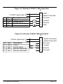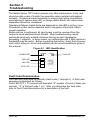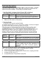
1
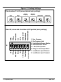
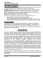
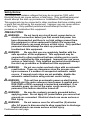
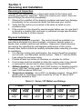
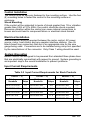
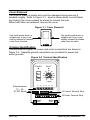
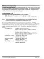
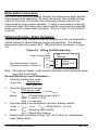
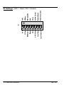
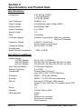
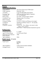
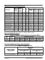
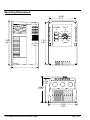
AC INVERTER Series 15P Potentiometer Adjustable Inverter Control Installation and Operating Manual 4/99 MN715P Table of Contents Section 1 Quick Start . . . . . . . . . . . . . . . . . . . . . . . . . . . . . . . . . . Section 2 General Information . . . . . . . . . . . . . . . . . . . . . . . . . Year 2000 Compliance . . . . . . . . . . . . . . . . . . . . . . . . . . . . . . . . CE Compliance . . . . . . . . . . . . . . . . . . . . . . . . . . . . . . . . . . . . . . Limited Warranty . . . . . . . . . . . . . . . . . . . . . . . . . . . . . . . . . . . . . Safety Notice . . . . . . . . . . . . . . . . . . . . . . . . . . . . . . . . . . . . . . . . Section 3 Receiving and Installation . . . . . . . . . . . . . . . . . . . . Receiving & Inspection . . . . . . . . . . . . . . . . . . . . . . . . . . . . . . . Physical Installation . . . . . . . . . . . . . . . . . . . . . . . . . . . . . . . . . . Control Installation . . . . . . . . . . . . . . . . . . . . . . . . . . . . . . . . . . . Electrical Installation . . . . . . . . . . . . . . . . . . . . . . . . . . . . . . . . . System Grounding . . . . . . . . . . . . . . . . . . . . . . . . . . . . . . . . . Input Current Requirements . . . . . . . . . . . . . . . . . . . . . . . . . . . Cover Removal . . . . . . . . . . . . . . . . . . . . . . . . . . . . . . . . . . . . Terminal Identification . . . . . . . . . . . . . . . . . . . . . . . . . . . . . . AC Line Connections . . . . . . . . . . . . . . . . . . . . . . . . . . . . . . . . . Protective Devices . . . . . . . . . . . . . . . . . . . . . . . . . . . . . . . . . Three Phase Wire Size and Protection Devices . . . . . . . . 115VAC 1 Phase Wire Size and Protection Devices . . . . 230VAC Single Phase Derating for Three Phase Controls Motor Brake Connections . . . . . . . . . . . . . . . . . . . . . . . . . . . . . Optional Dynamic Brake Hardware . . . . . . . . . . . . . . . . . . . . . Analog Input . . . . . . . . . . . . . . . . . . . . . . . . . . . . . . . . . . . . . . . . Digital Inputs . . . . . . . . . . . . . . . . . . . . . . . . . . . . . . . . . . . . . . . . Section 4 Setup and Operation . . . . . . . . . . . . . . . . . . . . . . . . . Overview . . . . . . . . . . . . . . . . . . . . . . . . . . . . . . . . . . . . . . . . . . . S1 Settings . . . . . . . . . . . . . . . . . . . . . . . . . . . . . . . . . . . . . . . . . Potentiometers P1 - P6 . . . . . . . . . . . . . . . . . . . . . . . . . . . . . . . Operation Examples . . . . . . . . . . . . . . . . . . . . . . . . . . . . . . . . . . Section 5 Troubleshooting . . . . . . . . . . . . . . . . . . . . . . . . . . . . . Section 6 Specifications and Product Data . . . . . . . . . . . . . . Specifications: . . . . . . . . . . . . . . . . . . . . . . . . . . . . . . . . . . . . . . . Ratings . . . . . . . . . . . . . . . . . . . . . . . . . . . . . . . . . . . . . . . . . . . . . Dynamic Brake Resistors . . . . . . . . . . . . . . . . . . . . . . . . . . . . . Terminal Tightening Torque Specifications . . . . . . . . . . . . . . . Mounting Dimensions . . . . . . . . . . . . . . . . . . . . . . . . . . . . . . . . . MN715P 1-1 2-1 2-1 2-1 2-1 2-2 3-1 3-1 3-1 3-2 3-2 3-2 3-2 3-3 3-3 3-4 3-4 3-5 3-6 3-7 3-8 3-8 3-9 3-10 4-1 4-1 4-2 4-4 4-5 5-1 6-1 6-1 6-3 6-3 6-3 6-4 Table of Contents i Section 1 Quick Start Overview The quick start procedure is as follows: 1. Read the Safety Notice and Precautions in section 2 of this manual. 2. Mount the control. Refer to Section 3, “Physical Installation” procedure. 3. Connect AC power. Refer to Section 3 “Control Installation”. 4. Connect the motor. Refer to Section 3, “Control Installation”. 5. Set the switches and adjust the potentiometers for desired operation. See Figure 1-1. The following procedure will help get your system up and running quickly, and will allow you to prove the motor and control operation. This procedure assumes that the control and motor are correctly installed. WARNING: Make sure that unexpected operation of the motor shaft during start up will not cause injury to personnel or damage to equipment. Power-up Procedure 1. 2. 3. Open cover. Be sure all S1 switches are OFF. Rotate the % Speed control on the front panel to 0% speed (fully counterclockwise position). 4. Turn power on. Be sure the “Fault” LED is off. 5. Press FWD. The LED on the FWD button should be on. 6. Rotate the % Speed control to 30%. The motor should rotate in the forward direction. Note: If the motor rotates in the reverse direction, turn power off and reverse any two of the three motor lead connections (J5-T1, T2 or T3). Turn power on and start at step 3 again. 7. Press STOP. The motor should decel to a stop and the LED on the STOP button should be on. 8. Press REV. The LED on the REV button should be on. 9. Rotate the % Speed control to 30%. The motor should rotate in the reverse direction. 10. Turn power off. The control is now ready to be configured for your application and placed into service. Refer to the appropriate connection diagram and setup procedure to configure your system. MN715P Quick Start 1-1 Figure 1-1 Factory Settings Potentiometers P1 to P6 (arrows indicate factory settings). Accel Decel 10 10 0.1 60 Minimum Frequency 60 Coast 0.1 1/ 2 Base 0 Maximum Frequency 1/ 2 Lim Lim Current Limit 50% 100% Torque Boost 0 15% Remote Speed Local Speed Remote Command 420mA Current 3 Wire 2 Wire 010V Voltage Auto Manual REV Disabled 2X Base 50 Hz Switch S1, shown with all switches in OFF position (factory settings). Local Command 1X Base 1-2 Quick Start REV Enabled 60 Hz S1 1 2 3 4 5 6 7 8 Base Frequency Max Frequency Limit Enable/Disable Reverse Rotation Manual/Automatic Restart 2 Wire/3 Wire Operation Voltage or Current Input Select Local/Remote Speed Reference Local/Remote Speed Command MN715P Section 2 General Information Year 2000 Compliance The motor control products listed below are manufactured or offered for sale by Baldor Electric and are certified to be year 2000 compliant. DC Motor Controls: Series BC100/200, BC19H, BC20H, TSD, UM, UMH. AC Motor Controls: Series ID10, ID1100, ID15H, ID15J, ID15P, ID15V, ZD17H, ZD18H, ID21H, ZD22H, SD23H, ZD24M, ZD25M, SD26M, BSC, DBSC, BTS, SBTS, FLEX, FLEX+, MINTDRIVE. Position Controllers: PMC, SmartMove, NextMove. Furthermore, year 2000 compliance means that the product will: Not use dates or perform any date processing. Date information is irrelevant to proper operation; and There are no problems or issues to address to ensure continued and proper operation of the product listed due to changes in century dates. CE Compliance A custom unit may be required, contact Baldor. Compliance to Directive 89/336/EEC is the responsibility of the system integrator. A control, motor and all system components must have proper shielding grounding and filtering as described in MN1383. Please refer to this manual for installation techniques for CE compliance. Limited Warranty For a period of two (2) years from the date of original purchase, BALDOR will repair or replace without charge controls and accessories which our examination proves to be defective in material or workmanship. This warranty is valid if the unit has not been tampered with by unauthorized persons, misused, abused, or improperly installed and has been used in accordance with the instructions and/or ratings supplied. This warranty is in lieu of any other warranty or guarantee expressed or implied. BALDOR shall not be held responsible for any expense (including installation and removal), inconvenience, or consequential damage, including injury to any person or property caused by items of our manufacture or sale. (Some states do not allow exclusion or limitation of incidental or consequential damages, so the above exclusion may not apply.) In any event, BALDOR’s total liability, under all circumstances, shall not exceed the full purchase price of the control. Claims for purchase price refunds, repairs, or replacements must be referred to BALDOR with all pertinent data as to the defect, the date purchased, the task performed by the control, and the problem encountered. No liability is assumed for expendable items such as fuses. Goods may be returned only with written notification including a BALDOR Return Authorization Number and any return shipments must be prepaid. MN715P General Information 2-1 Safety Notice: This equipment contains voltages that may be as great as 1000 volts! Electrical shock can cause serious or fatal injury. Only qualified personnel should attempt the start–up procedure or troubleshoot this equipment. This equipment may be connected to other machines that have rotating parts or parts that are driven by this equipment. Improper use can cause serious or fatal injury. Only qualified personnel should attempt the start–up procedure or troubleshoot this equipment. PRECAUTIONS: WARNING: Do not touch any circuit board, power device or electrical connection before you first ensure that power has been disconnected and there is no high voltage present from this equipment or other equipment to which it is connected. Electrical shock can cause serious or fatal injury. Only qualified personnel should attempt the start–up procedure or troubleshoot this equipment. WARNING: Be sure that you are completely familiar with the safe operation of this equipment. This equipment may be connected to other machines that have rotating parts or parts that are controlled by this equipment. Improper use can cause serious or fatal injury. Only qualified personnel should attempt the start–up procedure or troubleshoot this equipment. WARNING: Do not use motor overload relays with an automatic reset feature. These are dangerous since the process may injure someone if a sudden or unexpected automatic restart occurs. If manual reset relays are not available, disable the automatic restart feature using external control wiring. WARNING: This unit has an automatic power up start feature that will start the motor whenever input power is applied and a RUN (FWD or REV) command is issued and maintained. If an automatic power up start of the motor could cause injury to personnel, this feature should be turned off. WARNING: Be sure the system is properly grounded before applying power. Do not apply AC power before you ensure that grounds are connected. Electrical shock can cause serious or fatal injury. WARNING: Do not remove cover for at least five (5) minutes after AC power is disconnected to allow capacitors to discharge. Electrical shock can cause serious or fatal injury. Continued on next page. 2-2 General Information MN715P WARNING: Motor circuit may have high voltage present whenever AC power is applied, even when motor is not rotating. Electrical shock can cause serious or fatal injury. WARNING: Dynamic brake resistors may generate enough heat to ignite combustible materials. Keep all combustible materials and flammable vapors away from brake resistors. Caution: Disconnect motor leads (T1, T2 and T3) from control before you perform a “Megger” test on the motor. Failure to disconnect motor from the control will result in extensive damage to the control. The control is tested at the factory for high voltage / leakage resistance as part of Underwriters Laboratories Inc. requirements. Caution: Do not connect AC power to the Motor terminals T1, T2 and T3. Connecting AC power to these terminals may result in damage to the control. Caution: Baldor recommends not using “Grounded Leg Delta” transformer power leads that may create ground loops. Instead, we recommend using a four wire Wye. MN715P General Information 2-3 Section 3 Receiving and Installation Receiving & Inspection The Series 15P Inverter control is thoroughly tested at the factory and carefully packaged for shipment. When you receive your control, there are several things you should do immediately. 1. Observe the condition of the shipping container and report any damage immediately to the commercial carrier that delivered your control. 2. Verify that the control you received is the same as listed on your purchase order. 3. If the control is to be stored for several weeks before use, be sure that it is stored in a location that conforms to published storage specifications. (Refer to Section 6 of this manual). Physical Installation The mounting location is important. The control should be installed in an area that is protected from direct sunlight, corrosives, harmful gases or liquids, dust, metallic particles and vibration. Exposure to these elements can reduce the operating life and degrade performance of the control. Several other factors should be carefully evaluated when selecting a location for installation: 1. For effective cooling and maintenance, the control should be mounted on a smooth, non-flammable vertical surface. Table 3-1 lists the Watts Loss ratings for enclosure sizing. 2. Provide at least two inches of clearance on all sides for airflow. 3. Front access must be provided to allow the control cover to be opened or removed for service and to allow viewing of the Keypad LEDs. 4. Altitude derating. Up to 3300 feet (1000 meters), no derating required. Above 3300 feet, derate peak or continuous output current by 2% for each 1000 feet above 3300 feet. 5. Temperature derating. Up to 40°C, no derating required. Above 40°C, derate peak or continuous output current by 2% per °C above 40°C. Maximum ambient is 55°C. Table 3-1 Series 15P Watts Loss Ratings 115VAC 2.5kHz PWM 7.5kHz PWM 230VAC 2.5kHz PWM 7.5kHz PWM 460VAC 2.5kHz PWM 7.5kHz PWM 17 Watts/ 20 Watts/ 17 Watts/ 20 Watts/ 19 Watts/ 28 Watts/ Amp Amp Amp Amp Amp Amp MN715P Receiving and Installation 3-1 Control Installation The control must be securely fastened to the mounting surface. Use the four (4) mounting holes to fasten the control to the mounting surface or enclosure. Shock Mounting If the control will be subjected to levels of shock greater than 1G or vibration greater than 0.5G at 10 to 60Hz, the control should be shock mounted. Excessive vibration within the control can cause internal connections to loosen and could lead to component failure or electrical shock hazard. Electrical Installation Interconnection wiring is required between the motor control, AC power source, motor, host control and any operator interface stations. Use UL listed closed loop connectors that are of an appropriate size for the wire gauge being used. Connectors are to be installed using crimp tool specified by the manufacturer of the connector. Only Class 1 wiring should be used. System Grounding Baldor controls are designed to be powered from standard three phase lines that are electrically symmetrical with respect to ground. System grounding is an important step in the overall installation to prevent problems. Input Current Requirements Table 3-2 Input Current Requirements for Stock Products 115VAC – 1 230VAC – 3 Catalog Numbers 460VAC – 3 Catalog Numbers Input Amps ID15P1F33–ER 7.5 ID15P201–ER 4.8 ID15P401–ER 2.4 ID15P1F50–ER 10.2 ID15P201F5–ER 6.9 ID15P401F5–ER 3.5 ID15P1F75–ER 14.4 ID15P202–ER 7.8 ID15P402–ER 3.9 ID15P101–ER 16.6 ID15P203–ER 11.0 ID15P403–ER 5.5 ID15P405–ER 8.7 3-2 Receiving and Installation Input Amps Catalog Numbers Input Amps MN715P Cover Removal The cover is made of plastic and could be damaged during removal if handled roughly. Refer to Figure 3-1. Insert a screw driver or small blade tool and pry the cover outward as shown to release the side. When both sides are released, remove the cover. Figure 3-1 Cover Removal Use small screw driver or suitable tool to pry cover slightly outward to release cover from its catch. Use small screw driver or suitable tool to pry cover slightly outward to release cover from its catch. Terminal Identification The terminals for signal, AC power and motor connections are shown in Figure 3-2. Separate ground connections are provided for power and motor grounds. Figure 3-2 Terminal Identification POWER 40 FWD 60 70 20 STOP P1 50 30 REV Potentiometers P1 – P6 S1 DIP Switch FAULT P2 80 10 90 0 100 % Speed P3 P4 P5 P6 1 J4 Control Terminal Strip J5 Power Terminal Strip L1 L2 L3 R2 R1 B- T1 T2 T3 Power GND MN715P Motor GND Receiving and Installation 3-3 AC Line Connections A power disconnect should be installed between the input power service and the control for a fail-safe method to disconnect power. The control will remain in a powered-up condition until all input power is removed from the control and the internal bus voltage is discharged. Protective Devices Recommended fuse sizes are based on the following: 115% of maximum continuous current for time delay. 150% of maximum continuous current for Fast or Very Fast action. Note: These general size recommendations do not consider harmonic currents or ambient temperatures greater than 40°C. Be sure a suitable input power protection device is installed. Use the recommended circuit breaker or fuses listed in Tables 3-3 and 3-4 (Wire Size and Protection Devices). Input and output wire size is based on the use of copper conductor wire rated at 75 °C. The table is specified for NEMA B motors. Circuit Breaker: 1 phase, thermal magnetic. Equal to GE type THQ or TEB for 230VAC Fast Action Fuses: Very Fast Action Fuses: Time Delay Fuses: 3 phase, thermal magnetic. Equal to GE type THQ or TEB for 230VAC or Equal to GE type TED for 460VAC 115/230VAC, Buss KTN 460VAC, Buss KTS 115/230VAC, Buss JJN 460VAC, Buss JJS 115/230VAC, Buss FRN 460VAC, Buss FRS 3-4 Receiving and Installation MN715P Three Phase Wire Size and Protection Devices Table 3-3 Wire Size and Protection Devices - 3 phase Control Rating Input Output Volts HP 230 230 230 230 460 460 460 460 460 Inp t Input Breaker Amps 1 1.5 2 3 1 1.5 2 3 5 7 7 15 15 3 7 7 7 15 Inp t F Input Fuse se Wire Ga Gauge ge Fast Acting Amps Time Delay Amps AWG mm2 6 8 12 15 3 4 5 8 12 5 7 9 12 2.5 3.5 4.5 6.3 10 14 14 14 14 14 14 14 14 14 2.08 2.08 2.08 2.08 2.08 2.08 2.08 2.08 2.08 Note: All wire sizes are based on 75°C copper wire, 1% line impedance. Figure 3-3 Three Phase AC Power and Motor Connections L1 L2 L3 Earth Shield wires inside a metal conduit. L1 L2 L3 Baldor Series 15P Control T1 T2 T3 Metal conduit should be used to shield output wires (from T1, T2, T3 of control to T1, T2, T3 of motor). T2 T3 T1 MN715P G AC Motor is not provided with control. Receiving and Installation 3-5 115VAC 1 Phase Wire Size and Protection Devices Table 3-4 Wire Size and Protection Devices - 1 phase Control Output O tp t Rating HP 0.33 0.5 0.75 1.0 Inp t F Input Fuse se Wire Ga Gauge ge Input Breaker Amps Fast Acting Amps Time Delay Amps AWG mm2 10 12.5 17.5 20 12 15 20 25 10 15 17.5 20 14 14 12 12 2.08 2.08 3.31 3.31 Note: All wire sizes are based on 75°C copper wire, 1% line impedance. Figure 3-4 Single Phase AC Power and Motor Connections L1 N Earth Shield wires inside a metal conduit. L1 N Baldor Series 15P Control T1 T2 Motor wire should be sized using the 3 phase information in Table 3-3. T3 Metal conduit should be used to shield output wires (from T1, T2, T3 of control to T1, T2, T3 of motor). T2 T3 T1 G AC Motor is not provided with control. 3-6 Receiving and Installation MN715P 230VAC Single Phase Derating for Three Phase Controls Single phase AC input power can be used to power a three phase control. However, the continuous and peak current ratings of the control must be reduced by 35% (derated). Control Output O tp t Rating HP 0.75 1 1.5 2 3 Inp t F Input Fuse se Wire Ga Gauge ge Input Breaker Amps Fast Acting Amps Time Delay Amps AWG mm2 10 10 12.5 15 25 10 12 15 20 25 9 10 15 17.5 25 14 14 14 14 12 2.08 2.08 2.08 2.08 3.31 Note: All wire sizes are based on 75°C copper wire, 1% line impedance. Figure 3-5 Single Phase 230VAC Power and Motor Connections L1 L2 Earth Shield wires inside a metal conduit. L1 L2 L3 Baldor Series 15P Control T1 T2 Motor wire should be sized using the 3 phase information in Table 3-3. T3 Metal conduit should be used to shield output wires (from T1, T2, T3 of control to T1, T2, T3 of motor). T2 T3 T1 MN715P G AC Motor is not provided with control. Receiving and Installation 3-7 Motor Brake Connections For motors with spring set brakes, connect the brake power leads and the motor power leads separately. Because the inverter has variable voltage output to the motor, the inverter may not supply enough power at low frequencies for proper brake operation. If using a motor with an internally connected brake, the brake power leads must be connected to a separate power source for proper brake operation. Refer to Figure 3-2 for terminal locations. Optional Dynamic Brake Hardware Dynamic Brake (DB) Hardware must be installed on a flat, non-flammable, vertical surface to obtain effective cooling and operation. The ambient temperature must not exceed 80°C. DB connections are shown in Figure 3-6. Figure 3-6 Wiring for RGA Assembly J5 Power Terminal Strip See recommended Terminal Tightening Torques in Section 6. DB Terminals R1 R1 R2 R2 Optional Dynamic Brake Resistor Note: Although not shown, metal conduit should be used to shield all power wires and motor leads. General Machinery Load Calculations: 1. Calculate braking duty cycle: Duty Cycle 2. Braking Time Total Cycle Time Calculate deceleration torque: T Decel RPM change Wk 2 Friction (Lb.Ft.) 308 time where: 3. TDecel = Deceleration torque in lb-ft. Wk2 = Inertia in lb-ft2 time = In seconds Calculate watts to be dissipated in dynamic braking resistor: Watts T Decel S max S min Duty Cycle (0.0712) where: 4. Smax = Speed to start braking Smin = Speed after braking Multiply watts calculated in step 3 by 1.25 to allow for unanticipated loads (safety factor). 3-8 Receiving and Installation MN715P Analog Input (S1-7 = OFF) If S1-7 is OFF, the front panel % Speed potentiometer is selected. The J4 inputs are ignored. (S1-7 = ON) One analog input is available at J4-2 and J4-1 as shown in Figure 3-7. The input may be connected to a potentiometer as shown or an input signal can be applied to pin J4-2. The analog signal can be 0-10VDC or 4-20 mA as selected by S1–6 (seeTable 3-5). Note: A potentiometer value of 5k to 10k, 0.5 watt may be used. Figure 3-7 Analog Input J4 1 Analog Ground 2 Analog Input 1 3 Pot Reference 5k or 10k Command Pot J4 – Signal Source 0-10VDC or 4-20mA 1 Analog Ground 2 Analog Input 1 3 Not Used + See recommended terminal tightening torque in section 6. S1-6 “OFF” Voltage Mode “ON” Current Mode MN715P Table 3-5 S1-6 Switch Settings J4 Description J4-1 is ground. J4-2 accepts a 0-10VDC input (from a potentiometer or other signal source). J4-1 is negative side of the 4-20mA connection. J4-2 is positive side of the 4-20mA connection. Receiving and Installation 3-9 Digital Inputs (S1-8 = OFF) If S1-8 is OFF, the front panel commands FWD, REV and STOP are selected. The J4 inputs are ignored. (S1-8 = ON) Three inputs are available on the J4 connector. Switch S1-5 determines whether two wire or three wire operation is used. If two wire is selected (S1-5= OFF) the STOP input at J4-6 is not used. Note: Pressing the STOP switch on the front panel keypad will override the J4 commands and cause the motor to decel to a stop. 2 Wire Operation of Digital Inputs (S1-5 = OFF) J4-4 Forward Open – Disables forward operation. Decel to stop. Closed – Starts forward motor rotation. J4-5 Reverse Open – Disables reverse operation. Decel to stop. Closed – Starts reverse motor rotation. J4 1 GND 4 5 Forward 6 Reverse Not Used 3 Wire Operation of Digital Inputs (S1-5 = ON) J4 J4-4 Forward Momentary Closed – Starts forward 1 GND motor rotation. 4 Forward J4-5 Reverse Momentary Closed – Starts reverse 5 Reverse motor rotation. 6 Stop J4-6 Stop Momentary Open – Motor decels to stop. Note: Simultaneous closure of J4-4 and J4-5 will cause the motor to decel to stop if the motor is running. If the control is in a fault condition, simultaneous closure of these inputs will attempt a fault reset. 3-10 Receiving and Installation MN715P Section 4 Setup and Operation Overview The operator interface panel is shown in Figure 4-1. Figure 4-1 Operator Interface POWER 40 FWD 60 70 20 STOP P1 50 30 REV P1 – P6 S1 DIP Switch (All OFF = factory settings) FAULT P2 80 10 90 0 100 % Speed P3 P4 P5 P6 1 J4 Control Terminal Strip J5 Power Terminal Strip L1 L2 L3 R2 R1 B- T1 T2 T3 Power GND Motor GND POWER LED is on when AC input power is applied to the control. FAULT LED is on when a fault condition is present in the control. FWD Press FWD to initiate forward rotation of the motor, in local command mode. LED is on when control is in forward run mode. REV Press REV to initiate reverse rotation of the motor, in local command mode. LED is on when control is in reverse run mode. STOP Press STOP to initiate a stop sequence, in local or remote modes. Depending on the setting of potentiometer P2, the motor will either ramp or coast to a stop. The LED is on when the control is in stop mode. MN715P Setup and Operation 4-1 4-2 Setup and Operation Remote Command Remote Speed Local Speed Local Command 420mA Current 3 Wire 010V Voltage Auto REV Disabled 2X Base 50 Hz 2 Wire S1 Manual REV Enabled 1X Base 60 Hz S1 Settings (OFF = Open; ON = Closed) MN715P S1 Settings Continued Switch 1 2 3 Setting OFF ON OFF ON OFF ON OFF ON 4 5 6 7 8 OFF ON OFF ON OFF ON OFF ON Description Base Frequency = 60Hz Base Frequency = 50Hz Maximum frequency limit = Base Frequency (60/50Hz) Maximum frequency limit = 2 X Base Frequency (130 or 110 Hz) Reverse motor rotation ENABLED Does not allow reverse motor rotation Power up Start DISABLED (see notes) Power up Start ENABLED the control will resume operation as soon as power is applied. Power up start is disabled the first time you power up the drive (see notes). Terminal 2 wire mode (If S1-8 = ON) Terminal 3 wire mode (If S1-8 = ON) Analog input VOLTAGE (if S1-7 = ON) Analog input CURRENT (if S1-7 = ON) Use local speed reference (front panel potentiometer) Use remote speed reference (J4 connector) Use local commands (front panel FWD, REV, STOP) Use remote commands (J4 connector) Note 1: If power up start is ON and local commands are used, the drive will resume operation in the same FWD or REV direction when power is applied. Note 2: If power up start is ON and remote 2 wire commands are used, the drive will resume operation if the forward or reverse switch is still closed (2 wire). Note 2: If power up start is ON and remote 3 wire commands are used, the drive will not allow power up start operation (unless the momentary contacts stop and forward or reverse are manually held closed during power up). Note 4: After power down, if any S1 switch position is changed, power up start is cancelled. MN715P Setup and Operation 4-3 Potentiometers P1 - P6 (270° of rotation) Refer to Figure 4-1 for location of potentiometers. 10 Sec. ACCEL time – P1 The time required to reach the Maximum Frequency setting of P4. Accelerates at a linear rate. First half (0 to 135° )= 0.1 sec to 10 sec last half (135 - 270°) =10sec to 60 sec 0.1 Sec. 60 Sec. DECEL time – P2 10 Sec. The time required to ramp to a stop. The voltage and frequency to the motor are reduced at a linear rate. First half (0 to 135° )= 0.1 sec to 10 sec 60 last half (135 - 265°) =10 sec to 60 sec Sec. Coast (265 - 270°) = Coast - Allows motor to coast to stop. 0.1 Sec. Minimum frequency – P3 Sets the minimum output frequency to the motor . This is a percentage of the S1-1 base frequency setting. Maximum frequency – P4 Sets the maximum output frequency to the motor. This is a percentage of the S1-2 frequency limit setting. 0 1/ LIM 2 1/ F 2 Base LIM Current Limit – P5 50% to 100% of control rated amps. 50% 100% 0% 15% Torque Boost – P6 Increases the nominal motor starting voltage from 0 to 15% to increase starting torque. 4-4 Setup and Operation MN715P Operation Examples Operating the Control from the Front Panel To place the control in local speed and command mode, place S1-7 and S1-8 in the OFF position. Refer to Figure 4-1 for switch location. Table 4-1 Active Switches for Local Operation S1 Pos. Position and Description 7 OFF Local Speed Reference (front panel potentiometer) 8 OFF Local command input (front panel FWD, REV, STOP) The control can operate as follows: 1. Set the P1 through P6 potentiometers as desired. 2. Set switches S1-1, S1-2, S1-3 and S1-4 as desired. 3. Adjust the motor’s speed using the potentiometer on the front panel. 4. Press the FWD or REV keys on the front panel. 5. Press STOP on the front panel to stop motor rotation. Note: S1-7 and S1-8 can be set so that either or both can be local or remote inputs. The front panel potentiometer can be used with remote command inputs by placing S1-7 OFF and S1-8 ON. Also, a remote speed reference can be used while the front panel switches are used by placing S1-7 ON and S1-8 OFF. Speed Adjustment using a Remote Speed Reference To use an external potentiometer or other signal source, refer to Figures 4-2, 4-3 and 4-4. Figure 4-2 Remote Potentiometer 2 Wire Operation J4 S1 Pos. Description 1 GND 5 OFF 2 Wire 2 Speed Command 6 OFF Voltage mode 3 +10VDC 7 ON Remote Speed Ref. 4 Forward 8 ON Remote commands 5 Reverse 6 Not Used 1. 2. 3. 4. 5. Set the P1 through P6 potentiometers as desired. Set switches S1-1, S1-2, S1-3 and S1-4 as desired. Close the FWD or REV key (both Open = Stop). Adjust the motor’s speed using the potentiometer at J4-2. Press STOP on the front panel to stop motor rotation. MN715P Setup and Operation 4-5 Figure 4-3 Remote 0-10VDC 3 Wire Operation J4 0-10VDC signal input S1 5 6 7 8 Pos. ON OFF ON ON Description 3 Wire Voltage mode Remote Speed Ref. Remote commands 1 2 3 4 5 6 GND Speed Command Not used Forward Reverse Stop Figure 4-4 Remote 4-20mA 2 Wire Operation J4 4-20mA signal input S1 5 6 7 8 Pos. OFF ON ON ON Description 2 Wire Current mode Remote Speed Ref. Remote commands 4-6 Setup and Operation 1 2 3 4 5 6 –Speed Command +Speed Command Not used Forward Reverse Not used MN715P Section 5 Troubleshooting The Baldor Series 15P Control requires very little maintenance, if any, and should provide years of trouble free operation when installed and applied correctly. Occasional visual inspection to ensure tight wiring connections and cleaning to remove dust, dirt, or foreign debris which can reduce heat dissipation should be considered. Operational failures called faults are displayed on the LED’s as they occur. Procedures in this section describe how to recognize a fault and restore normal operation. Before service is performed, all input power must be removed from the control to avoid electrical shock hazard. Most troubleshooting can be performed using only a digital voltmeter having an input impedance exceeding 1 megohm. In some cases, an oscilloscope with 5 MHz minimum bandwidth may be useful. Before consulting the factory, check that all power and control wiring is correct and installed per the recommendations given in this manual. Figure 5-1 LED Identification POWER LED FWD LED REV LED STOP LED POWER FAULT Fault LED 40 FWD 50 60 30 REV 20 70 10 90 0 100 % Speed STOP 80 Fault Code Determination The Fault LED may blink to indicate a fault code (1 through 5). A fault code sequence is displayed as follows: Fault LED OFF = 1.5 second and then blink “X” number of times (2 times per second). “X” is the fault code 1 to 5. After you determine the fault code, refer to Fault Code Descriptions for a description of the fault. MN715P Troubleshooting 5-1 Fault Code Descriptions Five failure conditions are indicated by LED’s on the front panel. Carefully examine all LED’s (Power, Fault, FWD, REV and Stop) to determine the cause of the fault condition. Press Stop to reset the control. 1. Non Resettable hardware faults (Power LED is blinking) (HW Surge Current, HW Protect, Power Module faults) Power LED Fault LED Description Blinking 1 Blink Hardware fault is detected. High output current, or control board power supply failure. a. Check wiring to ensure a ground fault is not present. b. Make sure the load is not excessive. 2. Overload faults (2 second or 60 second overload faults) To indicate that the drive is in an overcurrent condition, but has not tripped, the FWD or REV LED will blink two times per second. If the drive goes to 0% Overload left, the drive will fault and then start counting back up to 100%. During this counting up, the drive is not resettable. During this “count–up” condition, the fault LED and the STOP LED’s will blink. This is the only condition in which both LED’s will be blinking. When the drive reaches 100% Overload left, the fault LED will continue to blink, however, the STOP LED will remain continuously ON. FWD or REV LED Blinking Fault LED Description 2 Blinks Peak current has exceeded its 2 or 60 second rated limits or continuous current limit exceeded. STOP LED Blinking Fault LED 2 Blinks Description The remaining % Overload has been exceeded. A timer begins and all drive operations are suspended until 100% Overload capacity is regained. Press Stop to reset the control. If error remains, try these steps to correct the fault. (You may have to wait for the % Overload timer to expire). a. Verify proper sizing of control and motor. b. If error occurred while ramping motor, check motor, coupling and load. c. Increase ACCEL time (P1). d. Increase/Decrease Torque Boost value (P2). 5-2 Troubleshooting MN715P 3. Bus faults (Over-voltage, Under-voltage or Precharge faults) Power LED Fault LED Description ON 3 blinks High or low DC bus voltage is detected or DC Bus charging error detected. Press Stop to reset the control, if error remains try these steps to correct the fault. a. Lengthen DECEL time (P2). b. Add external dynamic braking assemblies. c. Correct problem with motor load. d. Check dynamic brake hardware wiring. e. Verify proper AC line voltage. Use step down transformer if needed. Use line reactor to minimize spikes. f. Check power line disturbances (sags caused by start-up of other equipment). Monitor power line fluctuations with date and time imprint to isolate power problem. 4. Dynamic Brake or Over-temperature faults Power LED Fault LED Description ON 4 Blinks Dynamic Brake power limit or excessive control temperature. Press Stop to reset the control, if error remains try these steps to correct the fault. a. Correct motor loading. Verify proper sizing of control, motor and brake resistor. b. Relocate control to a cooler operating area. Add cooling fans or air conditioner to control cabinet. c. Remove debris from fan and heatsink surfaces. d. Verify fan operation. Replace fan or check fan wiring. 5. Microprocessor faults (Communication timeout, incompatible front end and power boards, EEPROM or Power Base ID faults) Power LED Fault LED Description ON 5 Blinks Cable defect or other internal problem. a. Press Stop to reset the control. b. Turn power OFF then ON (cycle power). If fault remains call Baldor. MN715P Troubleshooting 5-3 Section 6 Specifications and Product Data Specifications: Horsepower 0.33-1HP @ 115VAC 1-3 HP @ 230VAC 1-5 HP @ 460VAC Input Frequency Output Voltage Output Current Output Frequency Service Factor Duty Overload Capacity 50/60Hz ± 5% 0 to Maximum Input Voltage (RMS) See Ratings Table 0 to 130Hz 1.0 Continuous Constant Torque Mode: 200% for 2 seconds 150% for 60 seconds 0-10VDC, 4-20mA and Rotary control on front panel 5k or 10k, 1/2 Watt Frequency Setting Frequency Setting Potentiometer Rated Storage Temperature: – 30°C to +65°C Operating Conditions: Voltage Range: 115 VAC Models 230 VAC Models 460 VAC Models Input Line Impedance: Ambient Operating Temperature: 90-132 VAC 1 60/50Hz 180-264 VAC 3 60Hz/180-230 VAC 3 50Hz 342-528 VAC 3 60Hz/342-457 VAC 3 50Hz 1% Minimum Required 0 to +40°C Derate Output 2% per °C over 40°C to 55°C (130°F) Maximum Enclosure: Humidity: Altitude: NEMA 1: ER (suffix) Models NEMA 1: To 90% RH non-condensing Sea level to 3300 feet (1000 meters) Derate 2% per 1000 feet (303 meters) above 3300 feet Shock: Vibration: LED Indicators 1G 0.5G at 10Hz to 60Hz Power Fault Forward run command Reverse run command Stop command MN715P Specifications and Product Data 6-1 Display: Control Specifications: Control Method PWM Frequency V/Hz Ratio Transistor Type Torque Boost Brake Torque Accel/Decel Time Base Frequency Frequency Setting Accel/Decel Auto Start Protective Functions Sine wave Carrier input, PWM output Rated @ 7.5kHz Linear with adjustable Torque Boost IGBT (Insulated Gate Bipolar Transistor) 0 to 15% adjustable Up to 60%, external resistor required Separate rates, 0.1 to 60 sec. 50 or 60Hz 0-10VDC, 4-20mA, and Rotary on front panel Separate Accel/Decel rates (0.1 - 60 seconds) ON or OFF Inverter trip – Over voltage, over current, under voltage, motor overload Short Circuit – Phase to phase and phase to ground Analog Input: Potentiometer Input Input Full Scale Range Differential Input Common Mode Rejection Input Impedance 0 - 10VDC 0-10VDC and 4-20mA 40db 20k Digital Inputs: (3 Inputs) Digital Inputs Forward Reverse Stop Input Impedance 6.8k (Closed contacts standard) Leakage Current 10A Maximum 6-2 Specifications and Product Data MN715P Ratings Series 15P Stock Products Catalog No. Output Current Rated Input Volts Rated Output Volts HP kW Continuous 60 Sec. Overload 2 Sec. Overload 115 115 115 115 230 230 230 230 460 460 460 460 460 230 230 230 230 230 230 230 230 460 460 460 460 460 0.33 0.5 0.75 1.0 1 1.5 2 3 1 1.5 2 3 5 0.25 0.37 0.56 0.75 0.75 1.1 1.5 2.2 0.75 1.1 1.5 2.2 3.7 1.6 2.3 3.2 4.2 4.2 6.0 6.8 9.6 2.1 3.0 3.4 4.8 7.6 2.4 3.5 4.8 6.3 6.3 9.0 10.2 14.4 3.2 4.5 5.1 7.2 11.4 3.2 4.6 6.4 8.4 8.4 12.0 13.4 19.2 4.2 6.0 6.8 9.6 15.2 ID15P1F33-ER ID15P1F50-ER ID15P1F75-ER ID15P101-ER ID15P201-ER ID15P201F5-ER ID15P202-ER ID15P203-ER ID15P401-ER ID15P401F5-ER ID15P402-ER ID15P403-ER ID15P405-ER Note: All specifications are subject to change without notice. Dynamic Brake Resistors Table 6-2 Dynamic Braking Resistor Assemblies (RGA) Control VAC Minimum Oh Ohms 115/230 460 60 120 100 RGJ160 RGJ1120 200 RGJ260 RGJ2120 Continuous Rated Watts 600 1200 RGA660 RGA1260 RGA6160 RGA12120 2400 RGA2460 RGA24120 Terminal Tightening Torque Specifications Table 6-3 Torques for “ER” Control Voltage Rating VAC 115, 230 and 460 MN715P Tightening Torque Control Terminals Power Terminals (J4) (J5) Lb–in Nm Lb–in Nm 4 0.45 7 0.8 Specifications and Product Data 6-3 Mounting Dimensions 4.396 (112) POWER FWD FAULT 40 50 70 10 90 0 100 % Speed REV 20 7.602 (193) 7.210 (183) STOP 60 30 80 4.445 (113) 4.945 (126) 4.834 (123) 6-4 Specifications and Product Data MN715P BALDOR ELECTRIC COMPANY P.O. Box 2400 Fort Smith, AR 72902–2400 (501) 646–4711 Fax (501) 648–5792 Baldor Electric Company MN715P Printed in USA 4/99 C&J2500