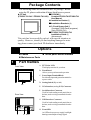
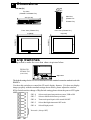
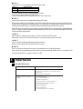
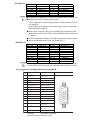
1
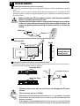
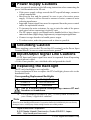
FP2500-T41-24V
FP2600-T41-24V Installation Guide
WARNINGS
• When connecting the FP2500-T41/FP2600-T41(hereafter referred to as the
"FP")'s power cord terminals to the FP Terminal Block, check first that the FP's
power supply is completely turned OFF, via a breaker, or similar unit.
• Whenever changing the backlight, to prevent electric shocks and burns, be
sure to unplug the FP's power cord and wear protective gloves.
• Do not open or remodel the FP unit, since it may lead to a fire or electric
shock.
• Do not use power beyond the FP's specified voltage range. Doing so may
cause a fire or an electric shock.
• Do not use the FP in an environment where flammable gases are present,
since operating the FP may cause an explosion.
• The FP uses a lithium battery for backing up its internal clock data. If the
battery is incorrectly replaced (i.e. its + and — sides are reversed), the battery
may explode. When changing the battery, please contact your local FP distributor.
• Do not use the FP unit as a warning device for critical alarms that can cause
serious operator injury, machine damage or production stoppage. Critical alarm
indicators and their control/activator units must be designed using stand-alone
hardware and/or mechanical interlocks.
• Do not use FP touch panel switches in life-related or important disaster prevention situations. For safety related switches, such as an emergency switch, be
sure to use a separate mechanical switch.
• To prevent operator injury or machine damage, be sure to design your machine operation system so that the machine will not malfunction due to a communication fault between the FP and its host controller.
• The FP is not appropriate for use with aircraft control devices, aerospace
equipment, central trunk data transmission (communication) devices, nuclear
power control devices, or medical life support equipment, due to these devices'
inherent requirements of extremely high levels of safety and reliability.
• When using the FP with transportation vehicles (trains, cars and ships), disaster and crime prevention devices, various types of safety equipment, non-life
support related medical devices, etc. Redundant and/or failsafe system designs should be used to ensure the proper degree of reliability and safety.
CAUTIONS
• Do not strike the FP touch panel with a hard or heavy object, or press on the touch
panel with too much force, since it may damage the display.
• Do not install the FP where the temperature will exceed its specified range.
• Be sure that water, liquids or metal particles do not enter the FP, since it may cause
a malfunction or a short circuit.
• Avoid installing the FP where sudden, large changes in temperature may occur.
These changes may cause condensation to form inside the unit, possibly causing a
malfunction.
• To prevent excessive heat from building up inside the FP, do not install it where its
ventilation holes may be blocked. Also, do not install or store the FP near high temperature equipment.
• Do not install or store the FP where direct sunlight or high levels of dust exist.
• Since the FP is a precision instrument, do not install or store it where either strong
shocks or excessive vibration may occur.
• Do not install or store the FP in an area containing chemicals or chemical fumes.
• Do not use paint thinner or organic solvents to clean the FP's case or screen.
• After turning the FP OFF, be sure to wait a few seconds before turning it ON again.
If the FP started too soon, it may not start up correctly.
UL/c-UL (CSA) Application Notes
The FP2500-T41-24V and FP2600-T41-24V are UL/c-UL (CSA) listed
products. (UL file No.E182139)
This unit conforms as a product to the following standards:
UL508 Industrial Control Equipment
UL1604 Electrical Equipment for use in Class 1 & 2 - Division 2, or Class
3 Hazardous Locations.
CAN/CSA C22.2 No.1010-1
MEASUREMENT AND CONTROL EQUIPMENT
(Safety requirements for electrical equipment for measurement and laboratory
use)
FP2500-T41-24V (UL Registration Model: 30B0003-01)
FP2600-T41-24V (UL Registration Model: 30B0003-02)
<Cautions>
• The FP must be used as a built-in component of an end-use product.
• This unit should be installed in the front face of a metal panel.
• If this unit is installed so as to cool itself naturally, be sure to install it in a
vertical panel. Also, be sure that the FP unit is mounted at least 100 mm
away from any adjacent structures or equipment. If these requirements are
not met, the heat generated by the FP unit’s internal components may cause
the unit to fail to meet UL/c-UL standard requirements.
UL1604 Conditions of Acceptability and Handling Cautions:
1. Power, input and output (I/O) wiring must be in accordance with Class I,
Division 2 wiring methods - Article 501- 4(b) of the National Electrical
Code, NFPA 70 within the United States, and in accordance with Section
18-152 of the Canadian Electrical Code for units installed within Canada.
2. Suitable for use in Class I, Division 2, Groups A, B, C and D, Hazardous
Locations.
3. WARNING: Explosion hazard - substitution of components may impair
suitability for Class I, Division 2.
4. WARNING: Explosion hazard - when in hazardous locations, turn power
OFF before replacing or wiring modules.
5. WARNING: Explosion hazard - do not disconnect equipment unless power
has been switched OFF, or the area is known to be non-hazardous.
CE Marking Notes
The FP2500-T41-24V and FP2600-T41-24V are CE marked products that
conform to EMC directives EN55011 Class A and EN61000-6-2.
* For detailed CE marking information, please contact your local FP
distributor.
Package Contents
The following items are included in the FP's package. Before
using the FP, please confirm that all items listed here are present.
FP unit
(FP2500-T41-24V / FP2600-T41-24V)
CD-ROM(1)
Contains FP2500-T41/FP2600-T41
User Manual
Installation Gasket (1)
Installation Brackets (4)
3.5 inch floppy disk(1)
(Contains Touch Panel programs)
(Only FP2500-T41)
FP2500-T41/FP2600-T41
Installation Guide (1)
(this manual)
This unit has been carefully packed, with special attention to
quality. However, should you find anything damaged or missing, please contact your local FP distributor immediately.
Options
Cables
Maintenance Parts
1
Touch panel driver software
Part Names
A: TFT Color LCD
The display monitor for your host.
Front View
B: Touch Panel
Allows you to perform touch operation.
H
C: Power Input Terminal Block
Provides the input and ground terminals for
a power cable.
D: Setting Switch (Dip switch)
A,B
E: VGA Interface (analog RGB) Connector
F: Serial Interface Connector
Used for both sending touch panel data to
the host, and receiving commands from the
host.
Rear View
G: USB Interface Connector
Used for both sending touch panel data to
the host, and receiving commands from the
host.
H: Front LED
C
D
EFG
An LED to detect power supply, backlight
burning out and input of image signal.
2 Dimensions
Unit:mm [in]
58[2.28]
8[0.31]
Top View
227.0[8.94]
(FP2500-T41/FP2600-T41)
301.0[11.85]
Front View (FP2500-T41)
Side View
(FP2500-T41
/FP2600-T41)
Front View (FP2600-T41)
317[12.48]
243[9.57]
243[9.57]
317[12.48]
3 Dip Switches
Dip switch is under the cover that shows in picture below.
FP2500-T41
/FP2600-T41
(rear view)
Dip-switch
The default settings for the FP were created based on the standard connection method used with
IBM-PCs.
Use these dip switches to control the FP unit's display features. If it does not display
images properly with the standard settings shown below, please adjust the switches.
If Dip Switch needs to change of Dip Switch setting,please reboot the power of FP again.
SW1
SW1-8
Selects touch panel transmission system, USB or SIO
SW1-7
Selects valid/invalid of factory set mode
SW1-6
Turns touch panel input's click sound ON/OFF
SW1-5
Selects Backlight Automatic OFF mode
SW1-4
Selects Display mode
Not used (Always OFF)
SW1-4
This switch is used to designate the FP's display mode.
SW1-4
Display Mode
OFF VGA Graphics & text mode
ON
VGA Graphics mode
For more details, refer to 4.'Analog RGB Interface'.
You can't use this switch on FP2600-T41.
Please set this switch OFF when the FP2600-T41 unit is used.
SW1-5
This switch controls the Automatic Backlight OFF mode.
When this switch is ON, and if there is no SIO transmission or touch operation performed for 5
minutes, the backlight turns off automatically. It will remain OFF until another SIO transmission or
touch operation takes place, at which time the backlight automatically turns back on.
If the FP unit is frequently not used, please set this switch ON to extend the life of the backlight.
Also, if a display related command is transmitted by the SIO, this Automatic Backlight OFF mode
will be automatically disabled.
SW1-6
This controls is used as the touch screen Click sound's ON/OFF switch.
When this is set to ON, a click will sound every time the touch panel is touched.
SW1-7
This is a switch to shift as adjustment mode at factory.
Please set this switch OFF when the FP unit is used.
SW1-8
This is a switch to change the data input (command control) of the touch panel.
Data output and command input/output will be performed from the USB connector when this is ON
and from the RS232C connector when it is OFF.
4 Interfaces
Analog RGB Interface
Input signal type
Analog RGB
Inputsignalcharacteristic
Image signal:analog RGB
Synchronous signal:TTL level,negative true or
positive true
Scanning type:non-interlace
Setting by OSD (On Screen
Display)
ContrastAdjustment
Sub ContrastAdjustment
Brightness Adjustment
HorizontalDisplay Position Adjustment
VerticalDisplay Position Adjustment
HorizontalAdjustment
Phase Adjustment
DimmerAdjustment
DefaultSetting (AllClearFunction)
( FP2500-T41)
Size
640 x 480
640 x 400
640 x 400
640 x 350
720 x 400
720 x 350
H Sync.
31.469±1 KHz
24.827±1 KHz
31.469±1 KHz
31.469±1 KHz
31.469±1 KHz
31.469±1 KHz
V Sync.
60±1 Hz
56±1 Hz
70±1 Hz
70±1 Hz
70±1 Hz
70±1 Hz
Dot Clock Range
25.175MHz±1%
21.053MHz±1%
25.175MHz±1%
25.175MHz±1%
28.322MHz±1%
28.322MHz±1%
Changeover from horizontal 720 pixels to 640 pixels is done via DIP switch.
When the horizontal 720 pixel signal is input;
-VGA Graphic & Text mode displays 640 pixels only and 80 pixels are
not displayed.
-VGA Graphic mode displays all pixels but images may be cut off if they
do not match the sampling .
With vertical 350 pixels, 400 pixels, including 50 pixels at the top and
at the bottom of the screen will be enlarged and displayed at 480 pixels
(1.2 times).
In VGA Graphic & text mode, the far right side's 80 pixels do not display.
Selection of display mode is done via switch SW1-4.
( FP2600-T41)
Size
800 x 600
800 x 600
640 x 480
640 x 480
640 x 480
640 x 400
640 x 400
640 x 350
720 x 400
720 x 350
H Sync.
35.156±1 KHz
37.879±1 KHz
31.469±1 KHz
35.000±1 KHz
37.861±1 KHz
24.827±1 KHz
31.469±1 KHz
31.469±1 KHz
31.469±1 KHz
31.469±1 KHz
V Sync.
56±1 Hz
60±1 Hz
60±1 Hz
66±1 Hz
72±1 Hz
56±1 Hz
70±1 Hz
70±1 Hz
70±1 Hz
70±1 Hz
Dot Clock Range
36.000MHz±1%
40.000MHz±1%
25.175MHz±1%
30.240MHz±1%
31.500MHz±1%
21.053MHz±1%
25.175MHz±1%
25.175MHz±1%
28.322MHz±1%
28.322MHz±1%
With vertical 350 pixels,400 pixels, including 50 pixels at the top and at the
bottom of the screen will be enlarged and displayed at 600 pixels (1.5 times).
Pin Assignments and Signal Names for Analog RGB
Pin
No.
SignalName
Condition
1
Analog R
R signalinput
2
Analog G
G signalinput
3
Analog B
B signalinput
4
Reserved
NC (spare forinput)
5
Digitalgrounding
DigitalsignalGND
6
Return R
R signalGND
7
Return G
G signalGND
8
Return B
B signalGND
9
Reserved
NC (spare forinput)
10
Digitalgrounding
DigitalsignalGND
11
Reserved
NC (spare forinput)
12
Reserved
NC (spare forinput)
13
H.SYNC
Horizontalsynchronous
signalinput
14
V.SYNC
Verticalsynchronous
signalinput
15
Reserved
NC (spare forinput)
Connector:
Mini Dsub 15 pin type
Connector set screw: Inch type (4-40)
Pin Location
15
5
11
1
Serial Interface
Serial Interface
Baud rate:9600 bps
Data length:8 bits
Parity:none
Stop bit:1
Pin Assignments and Signal Names for Serial Interface
Pin
No.
Signal
Name
1
CD
CarrierDetect(FP->Host)
2
RD
Receive Data (FP->Host)
3
SD
Send Data (FP<-Host)
4
DTR
Data TerminalReady (FP<-Host)
5
GND
Ground
6
DSR
Data SetReady (FP->Host)
7
RS
Requestto Send (FP<-Host)
8
CS
Clearto Send (FP->Host)
9
NC
No connection
Condition
Connector:
Connector set screw:
Pin Location
1
6
9
5
Dsub 9 pin female
Inch type (4-40)
Concerning Signal Names
Signal names used for the serial interface on FP units are designed to
match the pin order used on most PC serial interfaces, so that a
straight cable can be used to connect the two. Therefore, connect
each pin's signal to the same signal name on the PC side.
For example, pin #2 'RD' should be connected to the 'RD' input
terminal on the PC's connector.
Refer to section "2-4 Cable Diagrams" for each signal's direction.
USB Interface
Pin Assignments and Signal Names for USB Interface
Pin
NO.
1
2
3
4
Signal
Name
USB1-5V
USBD1(-)
USBD1(+)
GND
Condition
+5VIN
USBdata(-)
USBdata(+)
Ground
Communication
Connector:
Pin Location
1
2
3
4
Low speed Device
B type connector
5 Installation
Confirm the Installation Gasket's Positioning
It is strongly recommended that you use the gasket. It absorbs vibration in addition to repelling
water.
Place the FP on a level surface with the display panel facing downward. Check that the FP’s
installation gasket is seated securely into the gasket’s groove, which runs around the perimeter of
the panel’s frame.
• Before installing the FP into a cabinet or panel, check that the installation
gasket is securely attached to the unit.
• A gasket which has been used for a long period of time may have scratches
or dirt on it, and could have lost much of its dust and drip resistance. Be
sure to change the gasket periodically (or when scratches or dirt become
visible).
Rear face
Gasket
Create a Panel Cut and insert the FP into the panel from the front
2
Unit: mm [in]
R
Panel
r4
Panel
e
d
301.5 +1 [11.87 +0.04 ] un
0
227.5 +1
0
[8.96 +0.04
]
0
0
FP
FP
Panel thickness
1.6mm[0.06in] to
10mm[0.39in]
Attach the Installation Fasteners from Inside the Panel
The following figures show the four(4) fastener insertion slot locations. Insert each fastener's
hook into the slot and tighten it with a screwdriver.
Insertion Slots
Panel
Installation fastener
Top
Insertion Slots
FP
Bottom
• Tightening the screws with too much force can damage the FP's plastic case.
• The necessary torque is 0.5N•m.
• Depending on the installation panel's thickness, etc., the number of installation fasteners used may need to be increased to provide the desired level of
moisture resistance.
• If the number of the installation fasteners is increased, do not use the FP side
face's middle installation fastener hole. Instead, use the top and bottom holes.
6 Wiring
WARNINGS
• To avoid an electric shock, when connecting the FP's power cord terminals to the
power terminal block, confirm that the FP's power supply is completely turned
OFF, via a breaker, or similar unit.
• The FP2500-T41-24V/FP2600-T41-24V units are designed to use only DC24V
input. Any other power level can damage both the FP and the power supply.
• Since there is no power switch on the FP unit, be sure to attach a breaker-type
switch to its power cord.
• When the FG terminal is connected, be sure the wire is grounded.
Not grounding the FP unit will result in excess noise and vibration.
• Wherever possible, use thick wires (max. 2 mm2) for power terminals, and
twist the wire ends before attaching the ring terminals.
• Be sure to use the following size ring terminals.*1
Over φ 3.2mm(0.13in)
Under 6.0mm(0.24in)
• To avoid a short caused by loose ring terminals, be sure to use ring terminals
with an insulating sleeve.
Rear of FP
+ -
FG
+ - FG
Ring Terminals*1
Power Input
Terminal Block
*1 DC24V+=Positive electrode
DC24V-=Negative electrode
FG=Ground Terminal connected to the FP chassis
Suggested Ring Terminal : V2-MS3 (made by JST)
Connecting the FP Power Cord
When connecting the power cord, be sure to follow the procedures given below.
1. Confirm that the FP's Power Cord is unplugged from the power supply.
2. Use a screwdriver to remove the Power Input Terminal Block's clear plastic cover.
3. Unscrew the screws from the middle three (3) terminals, align the Ring
Terminals and re-attach the screws.
4. Confirm that the wires are connected correctly.
5. Replace the Power Input Terminal Block's clear plastic cover.
The torque required to tighten these screws is 0.5 to 0.6 N•m.
7 Power Supply Cautions
Please pay special attention to the following instructions when connecting the
power cord terminals to the FP unit.
• If the power supply voltage exceeds the FP's specified range, connect a
voltage transformer.
• Between the line and the ground, be sure to use a low noise power
supply. If there is still an excessive amount of noise, connect a noise
reducing transformer.
• Input and Output signal lines must be separated from the power control
cables for operational circuits.
• To increase the noise resistance, be sure to twist the ends of the power
cord wires before connecting it to the FP unit.
• The FP's power supply cord should not be bundled with or kept close to
main circuit lines (high voltage, high current), or input/output signal lines.
• Connect a surge absorber to handle power surges.
• To reduce noise, make the power cord as short as possible.
8 Grounding Caution
When attaching a wire to the FP's rear face FG terminal, (on the Power Input
Terminal Block), be sure to create an exclusive ground.*1
9 Input/Output Signal Line Cautions
• All FP Input and Output signal lines must be separated from all operating
circuit (power) cables.
• If this is not possible, use a shielded cable and ground the shield.
10 Replacing the Backlight
The FP unit's backlight is user replacable.
For an explanation of how to replace the FP's backlight, please refer to the
Installation Guide.
Corresponding Replacement Backlights
FP Unit
FP2500-T41
FP2600-T41
Backlight Model
GP577RT-BL00-MS
PS600-BU00
Use of a different model backlight may cause a FP malfunction or breakdown.
*1 Use a grounding resistance of 100Ω, a wire of 2mm2 or thicker, or
your country's applicable standard.
Note
Please be aware that Digital Electronics Corporation shall not be held liable by the user for any
damages, losses, or third party claims arising from the uses of this product.
Digital Electronics Corporation
8-2-52 Nanko Higashi, Suminoe-ku, Osaka 559-0031, Japan
URL: http://www.pro-face.com/
© 2001 Digital Electronics Corp.