1
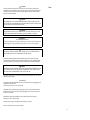
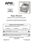
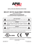
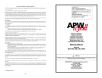
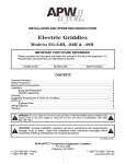
APW/WYOTT EQUIPMENT LIMITED WARRANTY
APW/WYOTT Foodservice Equipment Company warrants its equipment against defects in materials and workmanship, subject to the
following conditions:
This warranty applies to the original owner only and is not assignable.
Should any product fail to function in its intended manner under normal use within the limits defined in this warranty, at the option of
APW/WYOTT such product will be repaired or replaced by APW/WYOTT or its Authorized Service Agency. APW/WYOTT will only
be responsible for charges incurred or service performed by its Authorized Agencies. The use of other than APW/WYOTT Authorized
Service Agencies will void this warranty and APW/WYOTT will not be responsible for such work or any charges associated with same.
The closest APW/WYOTT Authorized Service Agency must be used.
IMPORTANT
FOR FUTURE REFERENCE
Please complete this information
and retain this manual for the life
of the equipment.
MODEL #———————————————————
SERIAL #———————————————————
DATE PURCHASED——————————————
For Warranty Service and/or Parts this
information is required.
This warranty covers products shipped into the 48 contiguous United States, Hawaii, metropolitan areas of Alaska and Canada. There will
be no labor coverage for equipment located on any island not connected by roadway to the mainland.
TIME PERIOD:
One-year parts, one-year labor, effective from the date of purchase by the original owner. The Authorized Service Agency may, at their
option, require proof of purchase. Parts replaced under this warranty are warranted for the unexpired portion of the original product
warranty only.
EXCEPTIONS:
*Gas/Electric Cookline - Models GCB, GCRB, GF, GGM, GGT, GHP-H, GWW, EBC, EF, EG, EHP, EWW Three (3)
Year Warranty on all component part, except switches and thermostats. (2 additional years on parts only - No labor on second or third
year.)
*Heat Strips - Models FD - Two (2) Year Warranty on element only - No labor second year.
*Glass Windows, Door Seals, Rubber Seals, Light Bulbs, Broiler Briquettes 90 Day Material Only - No labor.
In all cases parts covered by extended warranty will be shipped FOB the factory after the first year.
PORTABLE CARRY-IN PRODUCTS
Equipment weighing over 70 pounds or permanently installed will be serviced on-site as per the terms of this warranty. Equipment
weighing 70 pounds or under, and which is not permanently installed i.e., with cord and plug, is considered portable and is subject to the
following warranty handling limitations.
If portable equipment fails to operate in its intended manner on the first day of connection, or use, at APW/WYOTT's option or its
Authorized Service Agency, it will be serviced on-site or replaced.
From day two through the conclusion of this warranty, portable units must be taken or sent prepaid to the APW/WYOTT Authorized
Service Agency for in-warranty repairs. No mileage or travel charges are allowed on portable units after the first day of use. If the
customer wants on-site service they may receive same by paying the travel and mileage charges.
EXCLUSIONS:
The following conditions are not covered by warranty.
*Equipment failure relating to improper installation, improper utility connection or supply and problems due to ventilation.
*Equipment that has not been properly maintained, calibration of controls, adjustments, damage from improper cleaning
and water damaged controls.
*Equipment that has not been used in an appropriate manner, or has been subject to misuse or misapplication, neglect,
abuse, accident, alteration, negligence, damage during transit, delivery or installation, fire, flood, not or act of God.
*Equipment that has had the model number or serial number removed or altered.
If the equipment has been changed, altered, modified or repaired by other than a qualified service technician during or after the warranty
period then the manufacturer shall not be liable for any damages to any person or property which may result from the use of the
equipment thereafter.
This warranty does not cover services performed at overtime or premium labor rates. Should service be required at times which normally
involve overtime or premium labor rates, the owner shall be charged for the difference between normal service rates and such premium
rates APW/WYOTT does not assume any liability for extended delays in replacing or repairing any items beyond its control.
In all cases the use of other than APW/WYOTT authorized OEM replacement parts will void this warranty.
This equipment is intended for commercial use only. Warranty is void if equipment is installed in other than commercial application.
THE FOREGOING WARRANTY IS IN LIEU OF ANY AND ALL OTHER WARRANTIES EXPRESSED OR IMPLIED
INCLUDING ANY IMPLIED WARRANTY OF MERCHANTABILITY OR FITNESS AND CONSTITUTES THE ENTIRE
LIABILITY OF APW/WYOTT IN NO EVENT DOES THE LIMITED WARRANTY EXTEND BEYOND THE TERMS STATED
HEREIN.
PRODUCT MANUAL
Safety Instructions
Installation Instructions
Operation Instructions
Maintenance Instructions
Replacement Parts List
Warranty/Service Information
Gas Foodwarmer
Model GWW (Convertable)
Gas Hot Plate
Model GHP-W (Convertable)
Model GHP-H (Convertable)
FOR YOUR SAFETY
Do not store or use gasoline or other
flammable vapors or liquids in the
vicinity of this or any other appliance.
WARNING: Improper installation,
adjustment, alteration, service or
maintenance can cause property
damage, injury or death. Read the
installation, operating and maintenance
instructions thoroughly before
installing or servicing this equipment.
APW/WYOTT Foodservice Equipment Co.
P.O. Box 1829
Cheyenne, WY 82003
(307) 634-5801
FAX(307) 637-8071
P/N 88359-00 8/97
16
1
! CAUTION
The models are designed, built and sold for commercial use. If these models are positioned so the
general public can use the equipment, make sure that all cautions, warnings and operating instructions
are clearly posted near each unit so that anyone using the equipment will use it correctly and injure
themselves or harm the equipment.
Notes:
! WARNING
CHECK THE DATA PLATE ON THIS UNIT BEFORE INSTALLATION. CONNECT THE UNIT
ONLY TO THE VOLTAGE AND FREQUENCY LISTED ON THE DATA PLATE. CONNECT ONLY
TO 1 OR 3 PHASE AS LISTED ON THE DATA PLATE.
! WARNING
Improper installation, operation, service or maintenance can cause property damage, injury or death.
Read these instructions thoroughly before installing, operating, maintaining or servicing this
! WARNING
Electrical Grounding Instructions
This appliance is equipped with a three prong (grounding) plug for your protection against shock hazard and
should be plugged into a properly grounded three prong receptacle. Do not cut or remove from this plug.
! WARNING
DISCONNECT ELECTRICAL POWER. SUPPLY AND PLACE A TAG AT THE DISCONNECT
SWITCH INDICATING THAT YOU ARE WORKING ON THE CIRCUIT.
Install per the spacing requirements listed in the installation section of this manual. We strongly
recommend having a competent professional install this equipment. Such a person should be familiar
with local gas regulations. A gas company representative should approve the completed installation.
! WARNING
FOR YOUR SAFETY DO NOT STORE OR USE GASOLINE OR OTHER FLAMMABLE LIQUIDS
AND VAPORS IN THE VICINITY OF THIS OR ANY OTHER APPLIANCE. KEEP THE AREA
FREE AND CLEAR OF COMBUSTIBLES. (SEE ANZI Z83.14B, 1991)
Instructions to be followed if any one smells gas should be posted in a prominent place. These may be
obtained from the gas supplier.
GAS PRESSURE
The appliance and its individual shutoff valve must be disconnected from the gas supply piping system
during any pressure testing of that
system at test pressures in excess of 1/2 psi (3.45 kPa)
The appliance must be isolated from the gas supply piping system by closing its individual manual
shutoff valve during any pressure testing of the gas supply piping system at test pressures equal to or
less than 1/2 psi (3.45 kPa)
Maintenance and repair should be handled by a factory authorized agent. Before doing any
maintenance or repair, contact APW/Wyott.
Disconnect the power supply to the appliance before cleaning or sevicing unit.
Do not use this unit in the event of an electrical outage.
2
15
Congratulations on your purchase of APW/Wyott commercial cooking or refrigeration equipment.
APW/Wyott takes pride in the design and quality of our products. When used as intended and with
proper care and maintenance, you will experience years of reliable operation from this equipment.
To assure best results, it is important that you read and follow the instructions in this manual
carefully.
Notes:
The countertop foodwarmer provides countertop warming capabilities. This unit incorporates a
4000 BTU/Hr burner for effiecient operation. The countertop hot plate, Model GHP-W provides
countertop heating and cooking capabilities.This unit incorporates two 12,000 BTU/Hr burners for
fast and even cooking and heating.
TABLE OF CONTENTS:
Safety Precautions ......................4
Specifications ..............................5
Installation ...................................5
Gas Foodwarmer:
Lighting Instructions ..................6
Maintenance ................................7
Replacement Parts Lists .............8
Conversion ..................................9
Gas Hot Plate:
Lighting Instructions ................10
Maintenance ..............................11
Conversion ................................11
Replacement Parts List ....... 12-13
Notes .................................... 14-15
Warranty ....................................16
LOCATION OF DATA PLATE
The data plate for the gas hot plate is located on the back side of the front panel.
IMMEDIATELY INSPECT FOR SHIPPING DAMAGE
All containers should be examined for damage before and during unloading. The freight carrier has
assumed responsibility for its safe transit and delivery. If equipment is received damaged, either
apparent or concealed, a claim must be made with the delivering carrier.
A) Apparent damage or loss must be noted on the freight bill at the time of delivery. It must then be
signed by the carrier representative (Driver). If this is not done, the carrier may refuse the claim. The
carrier can supply the necessary forms.
B) Concealed damage or loss if not apparent until after equipment is uncrated, a request for
inspection must be made to the carrier within 15 days. The carrier should arrange an inspection. Be
certain to hold all contents and packaging material.
Installation and start-up should be performed by a qualified installer who thoroughly read,
understands and follows these instruction.
If you have questions concerning the installation, operation, maintenance or service of this product,
write Technical Service Department APW/Wyott Foodservice Equipment Company, P.O. Box 1829,
Cheyenne, WY 82003.
14
3
SAFETY PRECAUTIONS
Before installing and operating this equipment be sure everyone involved in its operation are fully trained and are aware of all
precautions. Accidents and problems can result by a failure to follow fundamental rules and precautions.
The following words and symbols, found in this manual, alert you to hazards to the operator, service personnel or the equipment. The
words are defined as follows:
! DANGER
This symbol warns of imminent hazard which will result in serious injury or death.
! WARNING
This symbol refers to a potential hazard or unsafe practice which could result in serious injury or death.
! CAUTION
This symbol refers to a potential hazard or unsafe practice which may result in minor or moderate injury or product or property damage.
NOTICE
This symbol refers to information that needs special attention or must be fully understood even though not dangerous.
NOTICE
This product is intended for commercial use only. Not for household use.
! CAUTION
The models are designed, built and sold for commercial use. If these models are positioned so the general public can use the equipment,
make sure that all cautions, warnings and operating instructions are clearly posted near each unit so that anyone using the equipment will
use it correctly and not injure themselves of harm the equipment.
! WARNING
SHOCK HAZARD
Do not open any panels that require the use of tools.
! WARNING
Improper installation, service, or maintenance can cause property damage, injury or death.
NOTICE THE UNIT, WHEN INSTALLED, MUST BE ELECTRICALLY GROUNDED AND COMPLY WITH LOCAL CODES, OR
IN THE ABSENCE OF LOCAL CODES, WITH THE NATIONAL ELECTRICAL CODE ANSI/NFPA 70-LATEST EDITION.
CANADIAN INSTALLATION MUST COMPLY WITH CSA-STANDARD C.22.2 No. 0 M1982 General Requirements - Canadian
Electrical Code, Part II, 109-M1981 - Commercial Cooking Appliances.
NOTICE Local codes regarding installation vary greatly from one area to another. The National Fire Protection Association, Inc. states in
its NFPA 96 latest edition that local codes are "authority having jurisdiction" when it comes to requirements for installation of equipment.
Therefore, installations should comply with all Local codes.
4
Replacement Parts List
GHP-H
Key
1
2
3
4
5
6
7
8
9
10
11
12
13
14
15
Part Number
Description
Quantity
22016-01 Top grate 1
820212-24 Drip pan, top
1
820674-24 Burner, front
1
20668-44 Oriface #44 (Natural) 2
20688-55 Oriface #55 (L.P)
2
20660-34 Gas manifold assembly
1
217074-00 Knob gaurd
2
87055-03 Knob
2
20680-00 Burner valve
2
20656-14 Pilot valve 1
820643-00 Drip pan, bottom
1
820675-24 Burner, rear
1
86321-00 Legs, adjustable
4
20656-12 Valve, manual
1
20661-00 Pressure regulator (Convertable) 1
13
Specifications
GAS FOODWARMER and HOT PLATES
These gas units are designed for countertop operation. They are used for holding products at serving
temperature and producing evenly cooked products.
Gas:
GWW
GHP-W
GHP-H
1 - 4,000 BTU/Hr. burner with 1 standing pilot. Convertable to natural or propane gas.
2 - 12,000 BTU/Hr. burners with 2 standing pilots. Convertable to natural or propane gas.
2 - 20,000 BTU/Hr. burners with 1 standing pilot. Convertable to natural or propane gas.
Dimensions:
GWW
GHP-W
GHP-H
14” W x 24-3/4” L x 16” H
12” W x 24” L x 11-3/8” H
14” W x 24” L x 14-3/4” H
Capacity:
GWW
22 Qts. Accepts 12” x 20” or fractional pans.
General Installation Instructions:
Ensure gas supply and gas type, as shown on unit nameplate agree.
Unit installation must conform with the National Fuel Gas Code, ANSI Z223.1-1996, the National Gas
Installation Code, CAN/CGA-B149.1, or the Propane Installation Code, CAN/CGA-B149.2 as
applicable and in accordance with local codes.
Screw legs into the permanently fastened nuts on the four corners of the unit and tighten by hand.
Level the unit by turning the adjustment screw at the bottom of each leg. Do not slide unit with legs
mounted, lift if necessary to move unit.
Replacement Parts List
GHP-W
Key
1
2
3
4
5
6
7
8
9
10
11
12
13
14
Part Number
820220-00
820212-24
820674-12
20668-52
20668-60
20660-34
217074-00
87055-03
20680-00
20656-14
820643-12
820675-12
20656-12
20661-00
Description
Top grate
Drip pan
Burner, front
Oriface #52 (Natural)
Oriface #60 (L.P)
Gas manifold assembly
Knob guard
Knob
Burner valve
Pilot valve
Drip pan, bottom
Burner, rear
Valve, manual
Pressure regulator (Convertable)
12
Quantity
1
1
1
2
2
1
2
2
2
2
1
1
1
1
Pipe gas supply to unit.
Pipe threading compound must be resistant to the action of liquefied petroleum gases.
Caution:
DO NOT use an open flame to check for leaks. Check all gas piping for leaks with
a soap and water soluton before operating unit.
These units are suitable for installation on combustible and noncombustible surfaces.
Noncombustible clearances:
0” sides
0” rear
Combusible clearances:
3” sides
3” rear
5
Maintenance:
Lighting Instructions:
Lighting instructions are located on the inside of the front panel.
Access to the mainfold and pilot are gained through the front panel.
Daily:
Thoroughly clean splash back, sides and front.
Lighting pilot burner:
1
2
3
4
5
Turn on main gas supply to unit, on-off valve located behind the unit.
Turn the burner control knob to "OFF" position. Open the front panel and wait at least 5 minutes to
allow any gas which may have accumulated in the burner compartment to escape.
Depress red button on the pilot safety valve and light through observation hole in manifold baffle.
Keep red button on pilot safety depressed for at least 1 minutes after pilot has lit. If pilot does not
light repeat this step.
To adjust the pilot flame, rotate knob next to the red button. Turning the knob, clockwise increases
the pilot flame. A properly sized pilot should be 1/2” to 3/4” long.
These units are equipped with factory preset regulator with an outlet pressure of 4” W.C.(water
column) for natural gas and 10" W.C. for propane gas supply, and should require no further
adjustment .
Weekly:
1.
Clean unit thoroughly. Clean stainless steel or chromed surfaces with a damp cloth and polish
with a soft, dry cloth. A detergent may be used for cleaning. To remove discolorations, use a
nonabrasive cleaner.
2.
To clean the bottom drip pan, remove the drip pan by reaching under the unit and lifting the rear
of the pan about one inch, slide the pan to the rear about one half inch, and dip the front end of
the pan free of the unit and slide pan forward between the front legs. To replace the pan, reverse
this procedure.
3.
Burner air shutter openings must be kept clean.
4.
Main burner ports must be kept clean. To clean burners, boil them in a strong solution of lye
water for 15 to 20 minutes. Then either brush with a wire brush or clean gas ports with a sharppointed metal instrument to insure open ports.
Lighting main burner:
Since the burner is lit from constantly burning pilot, turn knob to “HI” to put the unit in operation;
then adjust to any desired position between “LO” and “HI”.
Main burner air supply:
For efficient burner operation, a proper balance of gas volume and primary air supply must be
maintained which will result in complete combustion. Insufficient air supply results in a yellow
streaming flame. Primary air supply is controlled by an air shutter on the front of the burner.
Loosen the screws on the front of the burner, and adjust the air shutter to just eliminate the yellow
tips of the burner flame. Lock the air shutter in place by tightening the screws.
All burners are lit from constantly burning pilots. Turning the thermostat to the desired
temperature is all that is required to put the unit in service.
Do not permit fans to blow directly at the unit. Wherever posible, avoid open windows next to the
units’ sides or back. Avoid wall type fans which create air cross-currents within a room.
It is also necessary that sufficient air should be allowed to enter the room to compensate for the
amount of air removed by any ventilating system. Otherwise, a subnormal atmospheric pressure
will occur, affecting operation and causing undesirable working conditions.
A properly designed and installed hood will act as the heart of the ventilating system for the room
or area in which the unit is installed, and will leave the unit independent of changing draft
conditions.
All valves and thermostats must be checked and lubricated periodically. Consult the authorized
service representative in your area.
Conversion
For conversion from natural gas to propane (L.P.).
This conversion should be done before connecting the unit to the gas supply.
1.
Remove the knobs and front panel.
2.
Remove the main burners.
3.
Remove the oriface fittings from the valves.
4.
Replace the oriface fittings with the size recommended for propane (L.P.).
5.
Replace the main burners.
6.
With the unit on its back or side, reverse the plug in the pressure regulatoer. The marking on the
plug while facing out should match the type of gas supplied.
7.
Replace the front panel and knobs.
8.
Continue with the installation.
Note:
Manifold pressure should be checked after the unit is connected to the gas supply. It should
be 10 inches (25.4 cm) water column for (L.P.). Leak test all joints.
If you should have any questions or problems, contact your nearest APW/Wyott Service
Representative.
6
11
Maintenance:
Lighting Instructions:
Lighting instructions are located on the inside of the front panel.
Access to the mainfold and pilot valves are gained through the front panel. Access to the
pilot burner is gained by removing the top grate.
Lighting Pilot Burner:
1.
Turn all burners to the “OFF” position.
2.
Turn on the main gas supply to the unit.
3.
Light the pilot and adjust the pilot regulating valve to give a stable pilot flame.
4.
If the pilot is out, turn all control knobs to the “OFF’ position. Wait 5 minutes before attempting
to light the pilot.
5.
To adjust the pilot flame, turn sdjudting screw on the pilot valve so increase or decrease the size
of the pilot flame. Adjust until the pilot flame is approximately 1/2” to 3/4” tall.
Extended Shutdown:
Turn the manual shutoff valve to “OFF”; turn all control knobs to the “OFF” position and shut off
the pilot flame by turning the adjustment screw on the pilot valve.
The entire flue duct opening, located on the rear of the unit, must be left uncovered
Daily:
1.
This apoliance is not a cooking device. It is intended to keep hot cooked foods at serving
temperatures.
Caution:
Burner Ignition
Since the burner is lit from a constantly burning pilot, turn the control knob to “HI” to put the unit
into operation; then adjust to any desired position between “LO” and “HI”.
a.
b.
c.
Main Burner Air Supply:
For effiecient burner operation, a proper balance of gas volume and primary air supply must be
maintained which will result in complete combustion. Insufficient air supply results in a yellow
streaming flame. Primary air supply is controlled by an air shutter on the burner.
d.
The foodwarmer is for wet operation only. Do not operate the unit dry. If
the unit runs dry, follow these steps:
Turn the control knob to “OFF”.
Wait until the pan well is cool enough to be handled. Do not pour water in the hot pan well.
remove pan well and thoroughly wash the internal bottom surface per weekly cleaning
instructions.
replace pan well, add water and resume normal operation.
2.
For proper operation, add approximately three quarts of water in the pan well. Check amount of
water daily, or after every four hours of operation. Add water as necessary.
Loosen the screws on the front of the burner, and adjust the air shutter to elliminate the yellow on
the burner flame. Lock the air shutter in place by tightening the screws.
3.
The pan well is not intended for use as a food container, but only to store water. Food to be kept
warm must be in separate containers.
All burners are lit from constantly burning pilots, turning the control valve as desired is all that is
required to put the unit in service.
4.
Since the burner is lit from a constantly burning pilot, turn the control knob to “HI” to put the unit
in operation; then adjust to any desired position between “LO” and “HI”.
Do not permit fans to blow directly ot the unit. Wherever possible, avoid open windows next to
the unit’s sides or back. Avoid wall type fans which create air cross-currents within the room.
5.
Turn unit on about 15 to 20 minutes before use.
6.
Clean pan well and top surface daily. Clean unit regularly. A clean unit looks nicer, lasts longer
and performs better.
It is also necessary that sufficient air should be allowed to enter the room to compensate for the
amount of air removed by any ventilating system. Otherwise, a subnormal atmosphere will occur,
adversly affecting operation and causing undesirable working conditions.
A properly designed and installed hood will act as the heart of the ventilating system for the room
or area in which the unit is installed, and will leave the unit independent of changing draft
conditions.
Weekly:
Clean the pan well thoroughly. If necessary, use steel wool on warm pan well. A detergent may
also be used on the pan well to help clean it, but care must be taken to ensure that the detergent is
thourughly removed.
All valves must be checked and lubricated periodically. Consult the authorized service
representative in your area.
10
7
Conversion
For conversion from natural gas to propane (L.P.)
This conversion should be done before connecting the unit to the gas supply.
1.
2.
3.
4.
5.
6.
7.
8.
Remove the knobs and front panel.
Remove the supply tubes that go between the valves and the oriface fittings.
Remove the oriface fittings from the firebox. Change the orifaces to the size recommended for
propane (L.P.).
Replace the oriface fittings into the firebos.
Replace the supply tubes between the valves and the orifaces fittings.
With the unit on its back or side, reverse the plug in the pressure regulator. The marking on the
plug, facing out, should match the type of gas supply desired.
Replace the front panel and knobs.
Continue with the installation.
Note:
Mainifold pressure should be checked after connecting to the gas supply. It should be
10 inches (24.5 cm) water column for propane (L.P.). Leak test all joints.
If you have any questions or problems, contact your nearest APW/Wyott
Service Representative.
Replacement Parts List
Key
1
2
3
4
5
6
7
8
9
10
11
12
13
14
15
16
Part Number
31007-19
820171-00
20661-00
20656-07
20660-08
20680-00
20688-62
20688-74
20658-15
820164-00
20661-53
820168-01
820192-00
820183-00
86321-00
87053-03
Description
Pan well
Bottom panel
Pressure regulator (convertable)
Pilot shutoff valve
Manifold
Burner valve
Oriface spud #62 (natural gas)
Oriface spud #74 (propane gas)
Burner
Burner support bracket
Pilot
Pilot bracket
Pilot supply tubing
Pilot shield
Adjustable leg
Knob
8
Quantity
1
1
1
1
1
1
1
1
1
1
1
1
1
1
4
1
9