1
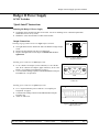
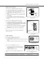
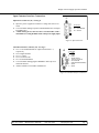
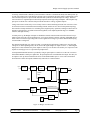
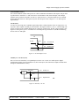
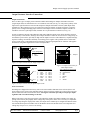
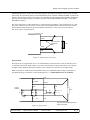
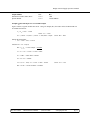
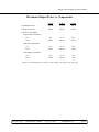
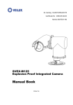
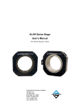
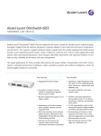
Badger II Power Supply Operator’s Manual Badger II Power Factor Corrected AC-DC Power Supply Operator’s Manual and ―Quick Install‖ Instructions www.mpwrs.com Rev. 05/11/2012 Mission Power Solutions (760) 631-6846 [email protected] Pg.1 Badger II Power Supply Operator’s Manual Badger II Power Supply AC-DC Switcher ―Quick Install‖ Instructions Mounting the Badger II Power Supply The Badger can be mounted on either of two sides. Use #8-32 mounting screws. Maximum penetration should not exceed 0.18″ (4,5 mm). Maintain 2″ (50,8 mm) clearance at either end for airflow. Output Connections Output Return Installing ring lugs and/or bus bars on single output card studs: Output The right stud is Positive and the left stud is the Return on single output cards. Remove the nut and place ring lug over output stud. Replace and tighten the nut to a torque of 10 in/lbs. Do not overtighten nuts. J3 Figure 1. Single (Maxi Module) Output Terminals Installing power connectors on dual output cards: J3-A1 is Positive for output 1 (lower connector); J3-A2 is the Return. J4-A1 is Positive for output 2 (upper connector); J4-A2 is the Return. For complete pin assignment, see page 9. Use ITT/Cannon mating receptacle P/N DAM7W2PK87 with pins P/N DM53745-1 or equivalent. J3/J4 Figure 2. Dual (Mini Modules) Output Connector Installing power connectors on quad output cards: J3 is a 16-pin Positronics power connector. For complete pin assignment, see page 9. Use Positronics mating connector P/N PLB16M7000 with pins P/N MC112N. Attach 12 AWG wire. 1 8 9 16 J3 Figure 3. Quad (Micro Modules) Output Connector Rev. 05/11/2012 Mission Power Solutions (760) 631-6846 [email protected] Pg. 2 Badger II Power Supply Operator’s Manual Remote Sense Connections Sense Connections on single (Maxi Module) output cards: The Badger II is shipped with Local Sense installed. If Remote Sense is desired, remove jumpers JMP1 and JMP2, located behind the sense connector. (See Fig. 4) Connector pin J3-1 is the +Sense and J3-3 is the –Sense. (See Fig. 6) Use Molex mating receptacle P/N 50-57-9403 with P/N 16-020103 terminals. Attach terminals to 22-24 AWG stranded twisted pair wire. Attach opposite end of sense lines to point where regulation is desired. Sense Connections on dual (Mini Module) output cards: The Badger II is shipped with Local Sense installed. If Remote Sense is desired, remove jumpers on JMP1 and JMP2 for output #1 (lower connector) and jumpers on JMP3 and JMP4 for output #2 (upper connector). (See Fig. 5) Connector pin J3-3 is the +Sense and J3-5 is the –Sense for output 1. J4-3 is the +Sense and J4-5 is the –Sense for output 2. (See Fig. 7) Use ITT/Cannon mating receptacle P/N DAM7W2PK87. Remote Sense Connections are not available on quad (Micro Module) output cards. J3 Remove Jumpers for Remote Sense Figure 4. Single (Maxi Module) Remote Sense Jumpers Remove Jumpers for Remote Sense Output 1 J3 Remove Jumpers for Remote Sense Output 2 Figure 5. Dual (Mini Module) Remote Sense Jumpers Trim Connections 3 Trim Connections on single (Maxi) output cards: 2 1 Pin 1 +Sense 2 Trim 3 –Sense J3-2 provides Trim access. (See Fig. 6) Use Molex mating receptacle P/N 50-57-9403 with P/N 16-02-0103 terminals. Attach 22-24 AWG stranded wire using Molex tool P/N 11-01-0118. J3 Figure 6. Single (Maxi Module) Trim Connections Trim Connections on dual (Mini ) output cards: J3-4 provides Trim access for output 1 (lower connector), and J4-4 provides Trim access for output 2 (upper connector). (See Fig. 7) Attach 22-24 AWG stranded wire. J3/J4 Trim Connections are not available on quad (Micro) output cards. Rev. 05/11/2012 Mission Power Solutions (760) 631-6846 Pin 1 2 3 4 5 N/C N/C +Sense Trim –Sense Figure 7. Dual (Mini Module) Trim Connections [email protected] Pg. 3 Badger II Power Supply Operator’s Manual Input/Customer Interface Connections Input Power Connector (J1) - See Fig. 8 Input AC power is applied to connector J1 using 3W3 Power Connector Use ITT/Cannon mating receptacle P/N DAM3W3SA197 with pins P/N DM53744-6 A fault clearing device, such as a fuse or circuit breaker, with a maximum 15 A rating should be used at the power supply input J1 Pin Out A1 Line A2 Line 2/Neutral A3 Ground Figure 8. Input Connector Customer Interface Connector (J2) - See Fig. 9 J2-1 to 3 are Enable/Disable for output card locations 1-3, respectively J2-4 is Signal Ground. J2-5 is +5 VDC J2-6 is AC Power OK J2-7 is General Shutdown Use ITT/Cannon mating plug P/N DE9PK87 with Amp cover shell P/N 205729-1 Attach terminals to 22-24 AWG stranded wire J2 Pin Out 1 E/D-1 2 E/D-2 3 E/D-3 4 Signal Ground 5 +5V Vcc @ 100 mA 6 AC Power OK 7 GSD (General Shutdown) 8 Spare 9 Spare Figure 9. Customer Interface Connector Rev. 05/11/2012 Mission Power Solutions (760) 631-6846 [email protected] Pg. 4 Badger II Power Supply Operator’s Manual Badger II Power Supply Power Factor Corrected AC-DC Switcher Overview The Badger II is a ruggedized, extremely low-profile AC-DC power supply that combines the advantages of power factor correction, high power density, and user-selected isolated outputs. Accepting input voltages of 85 to 254 VAC, and 85 to 380 VDC, the Badger II can provide up to 1,800 watts in a package size of 2.55″H x 7.0″W x 13.75″L. The Badger II can provide up to 12 isolated outputs and is factory configured to meet user requirements. Its inherent flexibility comes from its use of Vicor Maxi, Mini and Micro DC-DC converters. Standard Features Power Factor Correction: 0.99 at 115 VAC; 0.95 at 230 VAC Universal Input: 85-254 VAC, 47-500 Hz, or 85-380 VDC Power Output @ 45°C: up to 1,500 W at 220 VAC; 800 W at 110 VAC Up to 12 isolated outputs Fan cooled Up to 1,800 W @ 35°C; 1,500 W @ 45C; 750 W @ 65C Soft start for limiting inrush current Conducted EMI Compliance: FCC Class B, EN 55022 B; MIL-STD-461E, CE101 & CE102 Transient Protection: MIL-STD-704E -20, -40, or -55°C operating temperature Active Power Factor Correction .95 min @ 120/230 Full Load AC Power OK status signal Output Sequencing and General Shutdown Local Sense standard on all outputs. Remote Sense available with the removal of two jumpers Output overcurrent protection on all outputs Output overvoltage & overtemperature protection Ride-through (holdup) time: 20 ms at 1,200 W Size: 2.55″H x 7.0″W x 13.75″L Heavy-duty rugged enclosure designed for a high shock and vibration environment Extra cooling provided for higher output with increased altitude capability “D” shell connectors for input and output connections; bus bars provided for output currents greater than 40 Amps Optional conformal coating Technical Description The Badger II consists of an off-line single phase, power-factor-corrected front end, EMI filter, cooling fan, customer interface, associated housekeeping circuits, and a selection of Vicor’s DC-DC converters. Input AC mains voltage is applied to a 3-pin power connector. The input current is passed through an EMI filter to meet conducted noise limits. Rev. 05/11/2012 Mission Power Solutions (760) 631-6846 [email protected] Pg. 5 Badger II Power Supply Operator’s Manual At start-up, inrush current is limited by a PTC thermistor. The PTC is shunted out shortly after initial power-up by a DC bus voltage sense circuit driving a thyristor. After rectification, the input voltage is put through a boost converter that keeps the AC input current sinusoidal and synchronized with the input AC voltage. The boost converter delivers a regulated input to the hold-up capacitors and a high voltage backplane. The backplane supplies power to the DC-DC converters that provide the desired low voltage, regulated outputs. Voltage conversion is achieved by Vicor’s family of Zero-Current-Switching (ZCS) DC-DC converters. These are forward converters in which the main switching element switches at zero current. This patented topology has a number of unique attributes: low switching losses, high frequency operation (resulting in reduced size for magnetics and capacitors), excellent line and load regulation, wide output adjustment range, low EMI/RFI emission, and high efficiency. At initial power-up, the Badger II outputs are disabled to limit the inrush current and to allow the DC bus potential to settle out to the correct operating level. A low-power flyback converter operating with PWM currentmode control converts the high voltage DC bus into regulated low voltage to power the internal housekeeping circuits and DC cooling fans. The internal housekeeping Vcc comes up within 1 second after the application of input power. Once the high voltage bus is within operating limits, the AC Power OK signal changes its output to a TTL “1,” indicating the input power is OK, and allows the power outputs to come up 15-30 ms later. An auxiliary Vcc output of 5 VDC capable of sourcing up to 0.1 A is provided for peripheral use. An output Enable/Disable function is provided by using an optocoupler to control Vicor’s DC-DC converters. If the Enable/Disable control pin is pulled low, the optocoupler turns on and disables the output. The delay for an output to come up when measured from release of the Enable/Disable pin is 5-10 ms. The General Shutdown function controls all outputs simultaneously and works in a similar manner. Input Line Filter Soft Start Circuit Rectifier Boost Converter Output Card #1 Power Output Waveform Sample Current Sample PFC Control Output Card #2 Power Output Enable/Disable Control Customer Interface E/D Control Output Card #3 Power Output Fan Housekeeping Power Figure 10. Badger II Architecture Rev. 05/11/2012 Mission Power Solutions (760) 631-6846 [email protected] Pg. 6 Badger II Power Supply Operator’s Manual Interface Connections Input Terminal (J1) Input AC Power is applied to connector J1 using a 3W3 power connector. J1-A1 is Line (L1), J1-A2 is Line 2/ Neutral (L2/N) and J1-A3 is Earth Ground (GND) for safety. See Figure 8 (Pg 4). A fault clearing device, such as a fuse or circuit breaker, with a maximum 15 A rating at the power supply input is recommended. It should be sized to handle the start-up inrush of 30 A at 115 VAC and 60 A at 230 VAC. Customer Interface Connector (J2) Individual outputs for slots 1 through 3 can be disabled with a logic “0” at pins 1, 2 and 3 of J2. Signal Ground is available at pin 4. Auxiliary +5 Vcc @ 100 mA is available at pin 5. The AC Power OK at pin 6 is a logic “1” whenever AC input power is within tolerance. All outputs can be disabled by placing pin 7 at a logic “0” by connecting to signal ground at pin 4. Pins 8 and 9 are not used. See Figure 9 (Pg 4). Signal Ground (J2-4) Signal Ground on J2-4 is an isolated secondary ground reference for all J2 interfacing signals. This is not the same as Earth Ground on input power connector J1. Enable/Disable (J2-1 to J2-3) The Enable/Disable control pins allow outputs to be sequenced either on or off. J2-1 through J2-3 are the control pins for output cards 1 through 3, respectively. For dual or quad output cards, all outputs in that slot are enabled or disabled with a single control. The Enable/Disable pins should be pulled low to less than 0.7 V with respect to Signal Ground to disable the outputs. They will source 4 mA maximum. These pins should be opencircuited or allowed to exceed 4.5 V when enabled. Do not apply more than 5 V to these inputs at any time. Vcc J2 Enable/Disable Control TTL “1” (OFF) Disable Slot 1 1 General Shutdown TTL “0” (ON) 0 Signal Ground Badger 5 1 7 4 Figure 11. Enable/Disable and General Shutdown Rev. 05/11/2012 Mission Power Solutions (760) 631-6846 [email protected] Pg. 7 Badger II Power Supply Operator’s Manual General Shutdown (J2-7) The General Shutdown (GSD) control pin on J2-7 allows simultaneous shutdown of all outputs. This pin must be pulled down to less than 0.7 V and will source 4 mA maximum to shut down all outputs. The GSD pin should be open-circuited or allowed to exceed 4.5 V when not in use, or when the outputs are to be enabled. Do not apply more than 5V to this input at any time. Normal open-circuit voltage is 1.5-3 V with respect to Signal Ground. AC OK (J2-6) AC OK is an active high TTL-compatible signal and provides a status indication of the AC input power. It is on pin J2-6 and is capable of sinking 16 mA maximum. This signal switches to a TTL “1” when the high voltage bus exceeds low-line condition during turn-on. Upon loss of input power, the bus voltage will drop, causing the AC OK signal to go low. A minimum of 3 ms holdup time is provided for a 1,200 W load following the loss of the AC OK signal. +5V AC OK’ 2.5K J2-6 AC Power OK J2-4 Signal Ground PN2222 Figure 12. AC OK Output Circuit Auxiliary Vcc +5V/0.1A (J2-5) The Vcc on J2-5 is an auxiliary 5 V regulated power source. It is +5 VDC ±5% with respect to Signal Ground and can supply 100 mA maximum. It is short-circuit-proof, but if shorted, all outputs will shut down through the Enable/Disable circuitry. +5V/100mA J2-5 Auxiliary Vcc J2-4 Signal Ground 78M05 0.1 uF Figure 13. Auxiliary +5V Vcc Rev. 05/11/2012 Mission Power Solutions (760) 631-6846 [email protected] Pg. 8 Badger II Power Supply Operator’s Manual Output/Customer Interface Connections Output Connections There are three types of output power terminals available in the Badger II. Outputs from Maxi converters (single output cards) are terminated in two 10-32 stainless steel studs (see Fig. 14). The positive polarity of the output is the right stud when viewed from the output end. Outputs from Mini converters (dual output cards) terminate in a 7W2 connector (see Fig.15). Each power output is isolated, so outputs of positive or negative polarity can be configured through proper selection of the output reference terminals. Outputs from three or four Micro converters (quad output cards) terminate in a 16-pin Positronics connector (see Fig. 16). In order to minimize parasitic cable inductance and reduce EMI, the output power cables should be routed in close proximity to one another, and large current loops should be avoided. To avoid excessive voltage drop, do not undersize power cables, especially for high current outputs. Excessive cable inductance, coupled with large capacitive loading, can introduce instability in switching power supplies. This problem can be avoided with proper system design. Consult Mission Power Solutions’ Engineering Department for assistance with applications that use long cable lengths and excessive load capacitance. Output Return J4 Output 2 J3 Output 1 Output J3 Pin Assignments 1 +Sense 2 Trim 3 –Sense J3 Figure 14. Output Connections for Single Output Cards Figure 15. Output Connections for Dual Output Cards Pin 1 J3 Pin 9 J3 (Quad) Pin Assignments 1 +Out 1 9 +Out 1 2 –Out 1 10 –Out 1 3 +Out 2 11 +Out 2 4 –Out 2 12 –Out 2 5 +Out 3 13 +Out 3 6 –Out 3 14 –Out 3 7 +Out 4 15 +Out 4 8 –Out 4 16 –Out 4 J3 & J4 (Dual) Pin Assignments A1 +Output A2 Output Return 1 N/C 2 N/C 3 +Sense 4 Trim 5 –Sense Figure 16. Output Connections for Quad Output Cards Sense Connections The Badger II is shipped from the factory with Local Sense installed. If Remote Sense is desired, the Local Sense jumpers can be removed for individual outputs. If the Local Sense jumpers are removed, the sense lines must be connected at the load for Remote Sense. Leaving the sense lines open will prevent proper output regulation and can result in damage to the unit. When Local Sense is used, the power supply will regulate the output at the output terminals. The voltage appearing at the load may drop slightly due to voltage drop in the power cables. If it is necessary to compensate for voltage drop along the output power cables, the output can be trimmed up or configured for Remote Sense. Use stranded twisted pair 22-24 AWG wire for the Remote Sense lines. Remote Sense can compensate for a voltage drop of up to 0.5 V, or 0.25 V on each leg. Rev. 05/11/2012 Mission Power Solutions (760) 631-6846 [email protected] Pg. 9 Badger II Power Supply Operator’s Manual Installing Remote Sense requires the Local Sense jumpers to be removed (see Figures 4 and 5, Pg 3). On single output cards, the Local Sense jumpers are located behind the sense connector on JMP1 and JMP2. To remove the jumpers, make certain the power to the supply is off, and pull them off connectors JMP1 and JMP2. On dual output cards, the Local Sense jumpers are on either side of the card at JMP1and JMP2 for Output 1, and at JMP3 and JMP4 for Output 2. The sense connector for a single output card is a 3-pin connector providing the +Sense connection on J3-1 and the –Sense connection on J3-3. The sense connections for a dual output card are incorporated into the 7W2 Dshell connector(s) that also provide the output and trim connection(s). +Sense is pin 3 of each connector, and -Sense is pin 5 of each connector. +Out +Sense Use 22-24 AWG Twisted Pair Wire Load –Sense –Out Figure 17. Remote Sense Connections External Trim The trim pin at J3-2 (single output) or J3-4, J4-4 (dual output) is referenced to the -Sense pin and can be used for external control of the output voltage. A 10% increase to the trim pin voltage will result in a 10% increase in output voltage. Reducing the trim pin voltage by 10% will result in a 10% decrease in output voltage. Note: Converters are sometimes pre-trimmed at the factory if a nonstandard output voltage is requested. If a non-standard voltage is requested, or when trimming below 5 V, consult Mission Power for assistance. +Out R1 10-300Ω +Sense R8 R2 To Error Amplifier Trim + V1 R5 RTH R7 R3 –Sense – VREF Load R6 R4 20-200Ω Mission Power Solutions – –Out Figure 18. External Trim Rev. 05/11/2012 + V2 (760) 631-6846 Use 22-24 AWG Twisted Pair Wire for Sense Connections [email protected] Pg. 10 Badger II Power Supply Operator’s Manual Output Module VREF RTH Standard Vicor Maxi, Mini, Micro Special Module 1.23 V 1.23 V 1 kΩ Consult MPwrS Example: 10% trim adjust on a 12 V nominal output. Figure 18 shows a typical variable trim circuit. Using a 1k trimpot (R7), the resistor values for R6 and R8 can be calculated as follows: V1 =Vref + 10% = 1.353V Given: Vref = 1.23V IR5 = (1.353V - Vref)/RTH = (1.353V – 1.23V)/1k = 122A Given: RTH = 1k Setting the bottom limit: VR6 = 1.23V – 10% = 1.107V And since IR5 = IR6 = 122A, R6 = VR6/IR6 = 1.107V/122A = 9.074k V2 = V1 + VR6 = 1.353V + 1.107V =2.46V IR7 = V2/R7 = 2.46V/1k = 2.46mA IR8 = IR7 + IR6 = 2.58mA VR8 = (Vnom + 10%) – V2 = 13.2V – 2.46V = 10.74V Given: Vnom = 12V R8 = VR8/IR8 = 10.74V/2.58mA = 4.162k Rev. 05/11/2012 Mission Power Solutions (760) 631-6846 [email protected] Pg. 11 Badger II Power Supply Operator’s Manual Mechanical Considerations The Badger II can be mounted on either of two surfaces using standard 8-32 size screws. Maximum allowable torque is 20 in/lbs., and the maximum penetration is 0.18 in. (4.5 mm). When selecting a mounting location and orientation, the unit should be positioned so airflow is not restricted. Maintain a 2″ (50,8 mm) minimum clearance at both ends of the Badger II, and route all cables so airflow is not obstructed. The power supply draws air in at the fan/AC input side and exhausts air out the load side. If airflow ducting is used, avoid sharp turns that could create back pressure. The fans move approximately 75 CFM of air. Avoid excessive bending of output power cables after they are connected to the output terminals. For highcurrent outputs, use cable ties to support heavy cables and minimize mechanical stress on connectors. Be careful not to short out to neighboring outputs. The maximum torque recommended on output nuts is 10 in/lbs. Badger II Do’s and Don’ts Run the output (+/) power cables next to each other to minimize inductance. Insert proper fault protection at power supply input terminals (i.e., a fuse). Use proper size wires to avoid overheating and excessive voltage drop. Do not attempt to repair or modify the power supply in any manner. Do not restrict airflow to the unit. The cooling fan draws air into the unit and forces it out at the output power terminals. If sense jumpers are removed, do not leave sense lines open. Use twisted pair 22-24 AWG wire when installing Remote Sense. Rev. 05/11/2012 Mission Power Solutions (760) 631-6846 [email protected] Pg. 12 Badger II Power Supply Operator’s Manual Mechanical Drawing .19 13.75 AC INPUT CONNECTOR J1 STATUS/CONTROL CONNECTOR J2 OUTPUT SLOT 1 OUTPUT SLOT 2 -OUTPUT PIN OUTPUT SLOT 3 +OUTPUT PIN J1 J2 L1 L2/N WARNING SEE P RODUCT LABEL 7.00 -OUTPUT STUD 2.55 4-40 JACKSCREW J3 PIN A1 2X .50 4-40 JACKSCREW MOUNTING LOCATIONS 8-32 UNC-2B .180 MAX. DEPTH QTY = 2 9.000 2.38 .65 TRIM AND REMOTE SENSE CONNECTOR J3 DUAL OUTPUT SLOT ACCOMMODATES 1 OR 2 MINI MODULES +OUTPUT STUD +OUTPUT PIN PIN 1 -OUTPUT PIN REAR VIEW 4-40 JACKSCREW OUTPUT VIEW TYPICAL (13.75) 2X 9.000 2X 2.38 2X 1.00 OUTPUT SLOT 1 OUTPUT SLOT 2 OUTPUT SLOT 3 AIR BLOCK (2.55) 2X 5.000 (7.00) 2X .50 MOUNTING LOCATIONS 8-32 UNC-2B .180 MAX. DEPTH QTY=2 9.000 J3 PIN 9 2.38 REAR VIEW QUAD OUTPUT SLOT ACCOMMODATES 3 OR 4 MICRO MODULES OUTPUT VIEW OPTIONAL MOUNTING LOCATION 8-32 UNC-2B .180 MAX. DEPTH QTY = 4 Rev. 05/11/2012 Mission Power Solutions (760) 631-6846 [email protected] Pg. 13 Badger II Power Supply Operator’s Manual Specifications (Typical at 25C, nominal line and 75% load, unless otherwise specified) General Number of Outputs Efficiency Safety Approvals Maximum Output Power @ 35°C 1-12 80%, typical (depends on output V & I) None 800 W @ 110 VAC/VDC 1,800 W @ 220 VAC/VDC 10.0 lbs. 2.55"H (64,8mm) x 7.0"W (177,8mm) x 13.75"L (349,3mm) 1 Year Limited Product Weight Dimensions Warranty Input Input 85-254 VAC, 47-500 Hz 85-380 VDC 0.2% from 10% load to full load 30 A rms max @ 110 VAC 60 A rms max @ 220 VAC 20 ms at 1,200 W load FCC Class B, EN 55022 Class B MIL-STD-461E CE101, CE102 MIL-STD-461E CS101, CS114, CS115, CS116 0.99 (115 VAC, 800 W load) 0.95 (230 VAC, 1,200 W load) Primary to Chassis GND = 2,121 VDC Primary to Secondary = 4,242 VDC Secondary to Chassis GND = 500 VDC Line Regulation Inrush Current Ride-Through Time EMI—Conducted Emissions EMI—Conducted Susceptibility Power Factor Dielectric Withstand Output Parameter Setpoint Accuracy Load/line Regulation Temperature Regulation Long Term Drift Output Ripple – pp: ≤5 V ≥12 V Trim Total Remote Sense Compensation OVP Set Point Current Limit Over-Temperature Protection Rev. 05/11/2012 MIN. TYP. 0.5 0.02 0.002 0.02 MAX. 1 0.2 0.005 100 1 10 0.5 112 102 Mission Power Solutions 110 135 135 70 (760) 631-6846 UNITS NOTES % of VNOM % of VNOM 0% to 100% %C 20 to 65C %1 k hours mV % % of VNOM Volts % of VNOM % of Imax C 20 MHz bandwidth 20 MHz bandwidth 0.25 V max each leg Recycle power Automatic restart Varies with power level [email protected] Pg. 14 Badger II Power Supply Operator’s Manual Environmental Storage MIL-STDTemperature C-Grade Storage Temperature T-Grade Industrial H-Grade Grade Military Grade M-Grade Max Operating Temperature Range Commercial Grade C-Grade Operating Temperature T-Grade Industrial H-Grade Grade, Full Power M-GradeGrade, Half Power Industrial Humidity Military Grade, Full Power Altitude Military Grade, Half Power Operational Non-operational Commercial Grade, Full Power Shock Commercial Functional Grade, Half Power CrashWeight Safety Product Vibration Random Sine 810E 40C to 125C 40C to 125C 55C to 125C 55C to 125C 65C to 125C 65C to +125C (See temperature derating chart on next page) 40C to +125C 20C to +65C 40C to 65C 40C to 45C 40C to 65C 55C to 65C 40C to 65C 95%, non-condensing (conformal coating available) 55C to 45C 55C 65Cto 20,000 ft (6,000 m) Fulltopower 40,000 ft (12,000 m) 20C to +45C MIL-STD-810E, Method 516.4, Fig 516.4-4 20C +65C 40 g,to11 ms 7.075 lbs.g, 6 ms MIL-STD-810E, Method 514.4, Category 10, Figs 514.4-16 & -17 20-1000 Hz @ 0.04 g2/Hz; 2 kHz @ -6 dB/octave; 7.7 grms 5-14 Hz @ 0.2"; 14-33 Hz @ 2 g; 33-52 Hz @ 0.036"; 52-500 Hz @ 5 g Badger II Output Power vs. Input Voltage Do not exceed maximum power rating vs. temperature. See table on next page. Rev. 05/11/2012 Mission Power Solutions (760) 631-6846 [email protected] Pg. 15 Badger II Power Supply Operator’s Manual Maximum Output Power vs. Temperature @ 35°C @ 45°C @ 65°C Total Badger Power* 1,800 W 1,500 W 750 W Total Power per Slot 600 W 500 W 250 W ≤5 V 80A 80 A 40 A ≥12 V 600 W 500 W 250 W ≤5 V 40 A 40 A 20 A ≥12 V 250 W 200 W 100 W ≤5 V 20 A 20 A 10 A ≥12 V 150 W 150 W 75 W Total Power per Module Single Output Card (Maxi) Dual Output Card (Mini) Quad Output Card (Micro) *Do not exceed maximum power rating vs. input voltage. See graph on previous page. Rev. 05/11/2012 Mission Power Solutions (760) 631-6846 [email protected] Pg. 16 Badger II Power Supply Operator’s Manual Notes Rev. 05/11/2012 Mission Power Solutions (760) 631-6846 [email protected] Pg. 17