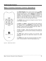
1
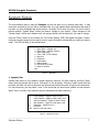
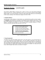
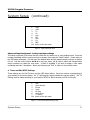
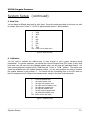
Stargate
Surround Sound Processor,
Preamplifier and D/A converter
___________________________________________________________________________
Owner’s Manual
MOON Stargate Processor
Table of Contents
Congratulations .......................................... 3
Introduction .............................................. 4
Unpacking and Warnings ............................. 5
Installation Tips ......................................... 6
System Setup ............................................ 7
Front Panel Controls ................................ 12
Full Function Remote Control Operation ...... 14
Full Function Remote Control Programming . 15
Basic Function Remote Control Operation ... 19
Rear Panel Connections ............................ 20
Typical Source Connections ...................... 22
5.1 Speaker Setup & Configuration ............ 23
6.1 Speaker Setup & Configuration ............ 24
7.1 Speaker Setup & Configuration ............. 25
Specifications ......................................... 26
Service and Warranty .............................. 27
www.simaudio.com
IMPORTANT: Please read this entire manual before using this product.
Installation and operating instructions inside.
____________________________________________________________________________________
MOON Stargate Processor
Congratulations!
Thank you for selecting the MOON Stargate Processor as a part of your your home-theater system.
This Processor has been designed to offer state-of-the-art high-end performance, retaining all the sonic
hallmarks on which Simaudio has made its reputation. We have spared no effort to ensure that it is
among the finest Surround Sound Processors available. We have been building high performance audio
equipment for over 20 years, and the know-how gained through our cumulative experience is an
important reason why MOON Processors are so musically satisfying.
The performance of your Stargate will continue to improve during the first four to six weeks of use.
This is the result of a “break-in” period required for the numerous high quality electronic parts used
throughout this Processor.
Please read this manual thoroughly to acquaint yourself with this product’s features prior to using it.
We hope you enjoy listening to the MOON Stargate Processor as much as the pride we have taken in
creating this fine audio product. We understand the power and emotion of music and build our
products with the goal of reproducing these elusive qualities.
For a component as sophisticated as this processor, it is of primary importance to take the time to
properly setup the unit prior to using it, otherwise you will not obtain the level of performance that
it is capable of. We strongly recommend that you read the “System Setup” section to help you
appropriately configure your MOON Stargate.
____________________________________________________________________________________
Congratulations
3
MOON Stargate Processor
Introduction
Your MOON Stargate Surround Processor incorporates many significant design features to achieve its
“world class” level of performance. This is an abbreviated list of the more important features:
Surround modes including Dolby® Digital Surround EX™, Dolby Digital® 5.1, Dolby® Surround Pro Logic® II,
DTS-ES™ Surround 6.1, DTS Digital Surround 5.1™, DTS Neo:6® and 7.1 Matrix Music Mode
Full-function programmable remote control.
Crystal CS43122 24-bit/192kHz digital-to-analog converters (4).
Crystal CS5396 24-bit/96kHz analog-to-digital converter for analog inputs.
9 analog inputs including a 7.1 channel "Analog Pass-Through" with defeatable analog filter and bass
management · Video switching via 7 inputs (composite, S-Video and component).
Full function bi-directional RS-232 port control and status for custom integration and automation.
"Rack mount ready" faceplate with removeable aluminum cheeks to cover holes when not in use.
Easy upgrade path based on "Open Architecture" flash-memory circuit design.
Crystal CS3310 digital volume controls (4) with switched resistive array technology.
Fully independent "2nd Zone" input and outputs for multi-room applications.
Three trigger outputs for remote operations.
"On-Screen Display" for options and calibration settings.
S-video to composite video signal converter.
AM/FM Stereo Tuner with presets.
Extremely rigid chassis construction to minimize the effects of external vibrations.
Improved reliabilty through the elimination of moving parts.
Designed to be powered up at all times for optimal performance.
Low operating temperature for a longer than normal life expectancy.
____________________________________________________________________________________
Introduction
4
MOON Stargate Processor
Unpacking and Warning!
The MOON Stargate Surround Processor should be removed from its box with care.
The following accessories should be included inside the box with your Processor:
9 AC power cable
9 2 removeable vertically mounted silver aluminum removeable cheeks that
9
9
9
9
cover the faceplate rack-mount holes
Full Function remote control with two ‘AAA’ batteries (USA and Canada only)
Basic Function (WRM) remote control with two ‘AAA’ batteries (USA and Canada only)
This owner’s manual
Warranty card (USA and Canada only)
As soon as the Processor is safely removed from its box and placed down, perform a thorough physical
inspection and report any physical damage to your dealer immediately. We suggest that you keep the
original packaging, and that it should be stored in a safe, dry place in case you’re required to transport
the Processor. The customized packaging is specially designed to protect the Processor from potential
damage that can arise when shipping such a product.
________________________________________________________________
WARNING!
To reduce the risk of fire or electric shock, do not expose this product to rain or
moisture. Do not attempt to “lift the ground” by removing the ground pin from
the AC cable. Make sure that your household electrical wiring supports proper
AC grounding techniques before plugging in this product. Keep the heat sinks
and top cover free of dust to allow for proper heat dissipation. Never expose this
product to extreme temperatures. Always connect the audio signal path cables
prior to connecting the AC mains.
CAUTION!
No user-serviceable parts inside. Do not remove top cover, as severe electrical
shock may result.
IMPORTANT!
Make sure that your local AC voltage complies with the unit’s label. Damage
caused by plugging thus amplifier into an AC receptacle of the wrong voltage will
not be covered by warranty.
____________________________________________________________________________________
Unpacking and Warning
5
MOON Stargate Processor
Installation Tips
The MOON Stargate Surround Processor / Preamplifier / D/A Converter should be placed on a rigid
surface to prevent any accidents such as falling over. It is highly recommended that it sits on its own
dedicated shelf.
You should never place another component on top of this Surround Processor. As well, you should
avoid placing it near a heat source or inside a closed cabinet that is not well ventilated. This could
compromise the Stargate’s performance and reliability.
In the event that you intend to place your Stargate in a rack mount type installation, we’ve made the
setup as user-friendly as possible. Simply remove each of the two (2) vertically mounted silver colored
aluminum cheeks found on either side of the front faceplate using an SAE 1/8 inch allen key; You will
find two (2) screws located on the rear of each side of the front faceplate which hold each aluminum
cheek in place. When removing these screws, make sure to keep one hand on the aluminum cheek so
that it won’t fall and cause any damage. Once all four (4) screws have been removed, you will have
exposed the four (4) rack mount holes and the MOON Stargate will be ready for mounting in a three
(3) rack space area. We recommend that you store the aluminum cheeks and their accompanying
mounting screws in a safe place in the event that you require them in the future.
Finally, you should make all of your audio and video signal connections prior to making the AC
connection between the Stargate and the AC wall outlet.
____________________________________________________________________________________
Installation Tips
6
MOON Stargate Processor
System Setup
The most effective way to setup the Stargate for the first time is to go through each step. It may
seem time consuming, but you will be rewarded with very high quality audio reproduction and ease of
use after you have completed the entire process. Normally, this is done only once; You won’t have to
perform another “System Setup” unless you make a change to your system. Future changes to the
“System Setup” will be much simpler since you may go directly into the section(s) you need to change.
Press the “Menu” button on the remote, the “On Screen Display” (OSD) will appear like figure 1 below.
Using the numeric keypad on the remote control, press the button corresponding to what you want to
setup. The OSD will jump to the related menu.
1.
2.
3.
4.
5.
6.
7.
8.
9.
1. Quick Setup – Speaker size
2. Quick Setup – Speaker distance
3. Input assignment
4. Tuner / PAL / NTSC Settings
5. Bass trim
6. Calibration
7. Compression
8. Status Display
9. DVD Audio Full Range
0. Reset to Defaults
Exit
Figure 1: Main Menu
1. Speaker Size
Speaker size refers to your speaker’s actual frequency response. For each channel, choosing “large”
means that the channel will be set to “full-range” by the processor; Choosing “small” means that the
processor will filter out the low bass from this channel and redirect this part of signal to the subwoofer.
For some channels, you may select “none” in the event that you don’t use a speaker for that channel.
When “none” is chosen, this channel’s signal is redirected to another channel(s).
1.
Front speakers - toggle to small or large
2.
Center speaker - toggle to small, large, none
3.
Surround speakers - toggle to small or large
4.
Rear speakers - toggle to small, large, none
5.
Subwoofer - toggle yes or no
6.
Crossover
Exit Return to the main menu
Figure 2: Speaker Size Menu
____________________________________________________________________________________
System Setup
7
MOON Stargate Processor
System Setup
(continued)
The Crossover setting (Option 6) will be set to a value of “none” in the event that the Subwoofer
(Option 5) is set to “no”. When the Subwoofer is set to “yes”, the Crossover will have a factory default
setting of 80Hz. This may be changed by using the “select” button which allows you to scroll through
all the crossover settings in 10Hz increments, ranging from 60Hz to 220Hz.
2. Speaker Distance
You will need to set the distance (in feet) between your optimal listening position and each speaker.
The Stargate uses this distance to calculate an accurate delay setting to apply to each channel. Press
the number according to the channel you wish to set. Then press the “Select” button to increase the
distance. The distance will increase by 1 foot increments until the maximum distance of 30 feet is
reached; the distance setting will then and start over at 1 foot.
1.
Set left front channel speaker distance
2.
Set center channel speaker distance
3.
Set right front channel speaker distance
4.
Set right surround channel speaker distance
5.
Set right back channel speaker distance
6.
Set left back channel speaker distance
7.
Set left surround channel speaker distance
Exit Return to the main menu
Figure 3: Speaker Distance Menu
3. Input Assignment
The default input assignment settings will be shown on the screen (figure 4). You can leave them as is
or you may re-assign any of the 6 digital inputs. Press the number corresponding to the input you
wish to change, then press “Select” button. Each time you press the “Select” button, the selected input
will scroll through each available digital input, and then return to the analog input. You may associate
each analog input to any digital input. Remember, each analog input is labeled on the back panel by its
name, unlike the digital inputs which are numbered 1 through 6.
____________________________________________________________________________________
System Setup
8
MOON Stargate Processor
System Setup
(continued)
1.
VCR1
2.
VCR2
3.
TV
4.
LD
5.
AUX
6.
SAT
7.
DVD
8.
CD
9.
TAPE
Exit Return to the main menu
Figure 4: Input Assignment Menu
Advanced Input Assignment: Analog input name change
This setup is optional in the event that you would like to rename one or more analog inputs. Press the
number associated with the input you want to rename, then press the “Guide” button. A new menu on
the OSD page will appear. On this menu the default name and the actual name are shown, as well as
five x’s. Use the cursor buttons STW X to move up, down, left & right to select and change letters
and/or numbers to create the new name. A blank is available if you wish to assign a new name
containing less than 5 characters. When you’re done press “Exit” to return to the previous menu.
4. Tuner and PAL/NTSC Settings
These settings are for the FM tuner and the OSD video setting. Press the number corresponding to
your location for the tuner setting. An “X” following the region indicates the current setting. The ‘TV
Setting’ must be made according to your location (NTSC for North America and PAL for Europe).
1.
USA
2.
South America
3.
Europe
4.
Japan
5.
Far East
6.
South Africa
7.
TV Setting
Exit Return to the main menu
Figure 5: Tuner and PAL/NTSC Settings Menu
____________________________________________________________________________________
System Setup
9
MOON Stargate Processor
System Setup
(continued)
5. Bass Trim
You can adjust a different bass level for each input. Press the number according to the input you wish
to change, then press “Vol S” or “Vol T” to adjust the bass level in 1 dB increments.
1.
2.
3.
4.
5.
6.
7.
8.
9.
Exit
VCR1
VCR2
TV
LD
AUX
SAT
DVD
CD
TAPE
Return to the main menu
Figure 6: Bass Trim Menu
6. Calibration
You will need to calibrate the relative level of each channel to get a proper surround sound
presentation. For precise calibration, you should use a Sound Pressure Level (SPL) meter. A fairly loud
pink noise tone will come from the selected speaker when you will press the associated button. For
each channel, adjust the output level to 75dB using the “Vol S” or “VolT ” buttons. The output level
should be calibrated from the optimal listening position, (i.e. the same position you used to measure
the speaker distance in step number 2). You should use the A-weighting filter on the SPL meter so
that low frequencies don’t influence the measurements, except in the case of the subwoofer.
1.
Front left speaker level
2.
Set center speaker level
3.
Set right front speaker level
4.
Set right surround speaker level
5.
Set right back speaker level
6.
Set left back speaker level
7.
Set left surround speaker level
8.
Set subwoofer speaker level
Exit Return to the main menu
Figure 7: Calibration Menu
____________________________________________________________________________________
System Setup
10
MOON Stargate Processor
System Setup
(continued)
7. Compression
This feature allows you to compress the dynamic range of the sound, which may be useful for low
volume listening late at night. When turned off, you get full dynamic range. When turned on, louder
passages are softened and softer passages are increased to maximize intelligibility of speech. Use the
“Select” button to toggle between on and off.
8. Status Display
Press the “Select” button to toggle between “Status Display” on and off. When turned on, an OSD
appears for 2 seconds each time you press a button. This OSD appears only when using the ‘main out’
composite or S-Video outputs. The selected input, surround mode and volume level will be displayed.
9. DVD Audio Full Range
Using the “Select” button to toggle between “yes” and “no”, this setting applies ONLY to the 7.1
“analog pass-through” input. When “yes” is selected, all signals present at the input will be sent to the
output, and be affected ONLY by the volume control. When “no” is selected, the filters are defined by
the “Speaker Size” settings you chose in the step number 1; Channels set to “large” will receive a full
bandwidth signal, while channels set to “small” will have limited low frequency response (80 Hz filter).
The analog filters will remove the low bass frequencies from the signal and redirect it to the subwoofer.
____________________________________________________________________________________
System Setup
11
MOON Stargate Processor
Front Panel Controls
Figure 8: Front panel of Moon Stargate Processor
The front panel look similar to Figure 8 (above). All twelve (12) of these buttons are replicated on the
Stargate’s remote control. What follows is a brief explanation of each one’s function.
Standby
Press to turn the unit on, and press again to put it in “Standby” mode. The equivalent button on the
remote is labeled “Power”, but will only put the processor in “Standby” mode; To turn the Stargate
on with the remote control, simply press the input you wish to use.
Stereo
Press to set the Stargate into “Stereo mode” (2 channel audio for front left & right speakers only).
Surround
Press to place the processor into “Surround” mode, whether it is Dolby® Surround Pro Logic® II or DTS
Neo:6®. The Stargate will automatically select the correct surround processing mode when it receives
digitally encoded surround signal such as Dolby Digital® 5.1, Dolby® Digital Surround EX™, DTS Digital
Surround 5.1™, or DTS-ES™ Surround 6.1. To set the default “Surround” processing mode, press the
“Mode” button on the remote control to toggle between the Dolby and DTS default “Surround”
processing modes.
____________________________________________________________________________________
Front Panel Controls
12
MOON Stargate Processor
Front Panel Controls
(continued)
Seek - and Seek +
Press to “Seek” up or down the frequency of the AM/FM tuner until you reach the desired radio station.
Note that the tuner must be the selected input for these buttons to work.
AM / FM
Press to toggle between the “AM” band and the “FM” band. Note that the tuner must be the selected
input for these buttons to work.
Input - and Input +
Press to scroll through the different source inputs until you reach the desired input (On the remote
control, each source input has its own dedicated button allowing for direct access selection). The
“Input –” and “Input +” buttons allow you to sequentially cascade through each of the possible 11
source inputs in the following order: DVD, TUNER, 7.1, CD, TAPE, AUX, SAT, TV, LD, VCR1 and VCR2.
Holding down either of these input buttons will allow only a single change of the selected source input;
You must press the button again to select the next (or previous) source input.
Vol - and Vol +
Press to adjust the “Volume” level up or down until you reach the desired level. The range for this
control is from ‘0’ for output to ‘99’ for full output.
Mute
Press to mute the sound; press again to return to the previous listening level.
Zone 2
Press to enter the “Second Zone” mode. Once in this mode, you will have five (5) seconds to adjust
the volume level or select another input, etc. before the Stargate automatically reverts back to the
“Main zone” for normal operation.
____________________________________________________________________________________
Front Panel Controls
13
MOON Stargate Processor
Full Function Remote Control Operation
The supplied remote control (figure 9) can operate up to eight (8)
different components and is programmable via a learning mode. The
eight (8) buttons located on the top 2 rows allow you to select the
component you wish to operate. Please refer to the next section
“Remote Control Programming” for instructions on how to manually
program this remote control.
To operate the Stargate with this remote control you must first press
the button labeled ‘AVC’ on the top left corner.
POWER: Puts the Stargate into “Standby” mode. This button cannot
turn the unit on; you must use one of the input selection buttons
located further down on the remote (i.e. DVD, LD, VCR1, VCR2, etc.).
MUTE: Places the unit in Mute mode – no output volume.
T/V: Toggle between NTSC and PAL video system (for OSD only).
CH S and CH T: Seek up/down AM/FM tuner frequency.
VOL S and VOL T: Adjusts output volume up/down.
GUIDE: The “Status Display” appears on screen.
MENU: The on screen “Setup” Menu appears on screen.
EXIT: Exit from the on screen Menus.
SELECT S W T X cursors used for SYSTEM SETUP functions
DVD, LD, VCR1, VCR2, SAT, AUX, CD, TV, TUNER, TAPE and 7.1:
Figure 9
Selects a source input and turns unit on from “Standby” mode.
SURR: Places the processor into Surround mode.
STEREO: Places the processor into Stereo mode.
MUSIC 7: Places the processor into 7.1 music mode.
MODE: Toggles between Dolby Surround Pro Logic® II Music, Dolby
Surround Pro Logic® II Movie, DTS Neo:6® Music and DTS
NEO:6® Cinema modes.
BASS: Sets the bass trim for the currently selected input.
1 thru 10: AM/FM Tuner Presets. To save the current radio station as
a ‘Preset’, press and hold one of the 10 preset buttons until
the sound mutes for approximately ½ second.
ZONE: Activate remote for ‘Zone 2’ function control (i.e. volume, seek,
input source selection, mute, off)
LIGHT: Turns on the remote’s backlighting (will auto shut off).
SHIFT: Toggle between AM and FM on the tuner.
This remote control uses four (4) AAA batteries which are included.
____________________________________________________________________________________
Full Function Remote Control Operation
14
MOON Stargate Processor
Full Function Remote Control Programming
This remote control allows you to transfer a command from a button on your source remote control
(original equipment remote control) to a button on the Stargate remote control. New commands can
be taught to any button in the CD, DVD, AUX, SAT, TV, VCR and CBL device modes, except on the
LIGHT button.
The remote control provides distinct visual feedback with LEDs (Light Emitting Diodes) that are located
at the top left of the remote control (Status LED) and under the Device buttons. The Status LED at the
top left of the remote operates in three colors (red, orange and green). The Device buttons have a red
color LED behind them. These LEDs will assist you in programming in the learning section of the
remote control.
Learning a New Command
Select a Device mode in which you would like to teach the new command. For example, if you wanted
to learn a new command to the PREV CH button in the TV mode on the remote, you would select the
TV Device button and use the instructions below to teach the new command to the PREV CH button.
Step 1:
Press the Device button and the SELECT button simultaneously and hold until the orange Status
LED and the Device button turn on and remain lit.
Step 2:
On the remote control, press the button that is to be taught the new command. The orange
Status LED will begin to flash continuously. The Device LED will turn off.
Step 3:
On the source remote control (original remote control), press and hold the button for the
command to be learned until the Status LED on the remote turns green. Release the button on
the source remote control.
Step 4:
Press the button on the source remote control, once again to verify that the new command has
been learned correctly. The Status LED will flash green twice and then turn to a steady orange
color indicating that the programming was successful. The Device LED will turn on.
Repeat
Steps 2 through 4 for any other buttons to be taught in the Device mode selected in Step 1.
Step 5:
Once you have completed learning new commands to the buttons in the selected Device mode
you must save the programmed information. Press and hold the Device button and SELECT
button simultaneously and hold until the orange Status LED flashes twice. The Device button will
turn off.
Repeat the above for any other Device modes starting from Step 1.
____________________________________________________________________________________
Full Function Remote Control Programming
15
MOON Stargate Processor
Full Function Remote Control Programming
Erasing a Learned Command From a Button
Step 1:
Press the Device button and SELECT buttons simultaneously and hold until the orange Status
LED and the Device button turn on and remain lit.
Step 2:
On the remote control, press the button that is to be erased. The orange Status LED will flash
continuously and the Device button will turn off.
Step 3:
Press the LIGHT button. The green status LED will flash twice, then turn to a steady orange. The
Device button will turn on.
Repeat
From Step 2 for any other buttons to be erased in the selected Device mode.
Step 4:
To exit this feature, press and hold the Device button and the SELECT button simultaneously
once again. The orange Status LED will flash twice and then turn off. The Device button will turn
off.
Erasing All the Learned Commands in One Device Mode
Step 1:
Press the Device button and SELECT buttons simultaneously and hold until the orange Status
LED and the Device button turn on and remain lit.
Step 2:
Press and hold the LIGHT button. The red Status LED will flash five times. Release the LIGHT
button. The Status LED will then flash green twice and then the Device button will turn off. The
Status LED will go to a constant orange indicating that all the learned information on buttons in
the Device mode have been erased. The Device button will turn on.
Step 3:
To exit this feature, press and hold the Device button and the SELECT button simultaneously.
The orange Status LED will flash twice and then turn off. The Device button will turn off.
Erasing All of the Learned Commands in All Device Modes
Press and hold the TV Device button and the LIGHT button simultaneously. The red Status LED will
flash continuously. The Status LED will then flash green once, orange once and then turn off, indicating
that all of the learned commands on all of the Device modes on the remote control have been erased.
Warning: This procedure will erase all learned commands on all buttons
in the CD, DVD, AUX, SAT, TV, VCR and CBL device modes.
____________________________________________________________________________________
Full Function Remote Control Programming
16
MOON Stargate Processor
Full Function Remote Control Programming
Volume Punch Through
You can set the audio volume controls (VOL S, VOL T and MUTE) to operate on any of the eight (8)
Device modes.
Step 1:
Press the Device and MUTE buttons, simultaneously.
Step 2:
Press the VOL S button.
Step 3:
Press the AVC device button to select the type of volume you wish to operate in that mode.
Example:
If you wish to have the AVC volume operate in the DVD mode, press the DVD Device button in
Step 1. above and the AVC Device button in Step 3.
Programming a Macro Sequence
Macro buttons (M1, M2, M3, M4 and POWER) can send out a sequence of up to ten (10) commands by
pressing one (1) button. Macros can be programmed in both the AVC and SAT modes, and they can
be accessed in other modes. If a macro is programmed in the AVC mode, that macro can also be
accessed in the CD, DVD, and AUX modes. If a macro is programmed in the SAT mode, that macro
can also be accessed in the TV, VCR and CBL modes. Macros can also be used to turn on or turn off
up to five (5) components or select favorite channels, etc.
Step 1:
Press a Device button (AVC or SAT) and the MUTE button simultaneously. Hold both buttons
until the red light under the Device button turns on.
Step 2:
Press one of the five macro buttons (M1, M2, M3, M4 or Power) that you wish to program.
The red light under the Device button will blink once for each subsequent button press.
Step 3:
Press up to 10 commands you would like to include in the macro sequence. Pressing a Device
button to change modes is counted as one command. Note: The Power On/Off command, for
devices other than the AVC receiver, is programmed into a macro using the MUTE button.
Step 4:
Press the CH S button to store the commands. The red Status LED and the Device button will
blink twice to confirm the program and then turn off.
To erase a macro sequence follow the above steps 1, 2 & 4 without going through step 3.
____________________________________________________________________________________
Full Function Remote Control Programming
17
MOON Stargate Processor
Full Function Remote Control Programming
Example for Programming a Macro Sequence
To program the M1 button in the AVC mode to power on the receiver, power on the CD, power on the
TV and power on the VCR:
Step 1:
Press the AVC button and MUTE buttons simultaneously. Hold both buttons until the red light
under the AVC button turns on. The red light will blink once during each subsequent press of a
button.
Step 2:
Press the M1 button to select the M1 macro.
Step 3:
Programming the M1 macro button: Press the AVC button to select the AVC Power command.
Press the CD Device button to select the CD mode. Press the MUTE button to select the CD
Power command. Press the TV Device button to select the TV mode. Press the MUTE button to
select the TV Power command. Press the VCR Device button to select the VCR mode. Press the
MUTE button to select the VCR Power command.
Step 4:
Press the CH S button. The red light under the AVC button will blink twice and then turn off
indicating that the macro sequence has been stored.
____________________________________________________________________________________
Full Function Remote Control Programming
18
MOON Stargate Processor
Basic Function Remote Control Operation
The MOON Stargate uses a second remote control, the ‘WRM’
basic function (figure 10). The main purpose of the ‘WRM’ is for
everyday remote operation once the Stargate has been properly
calibrated. This remote uses two AAA batteries (included). To
install them, use the supplied Allen key to remove the three screws
located on the back plate; insert the batteries in the correct
direction and then screw the back plate back into place.
The STANDBY button will switch the Stargate from either ‘Stand by’
to ‘On’ mode or vice versa.
The INPUT + and INPUT – buttons perform the same function as
the buttons located on the Stargate’s front panel (refer to page
12), allowing you to sequentially cascade through each of the
possible 11 source inputs in the following order: DVD, TUNER, 7.1,
CD, TAPE, AUX, SAT, TV, LD, VCR1 and VCR2.
The VOL + and VOL – buttons also perform the same function as
the buttons located on the front panel: increasing or decreasing the
output volume
The SURR button places the processor into “Surround” mode
exactly the same way as the same button located on the unit’s
front panel.
The STEREO button places the processor/preamplifier into “Stereo
mode” (2-channel audio for front left & right speakers only).
Figure 10: WRM Remote Control
____________________________________________________________________________________
Basic Function Remote Control Operation
19
MOON Stargate Processor
Rear Panel Connections
Figure 11: Rear panel of Moon Stargate Surround Processor
Audio & Video Signal Connections
The rear panel is divided into different sections whereby the connectors are grouped together in a
logical manner. The digital audio inputs are grouped together and are labeled “DIG 1” through “DIG 6”.
As previously discussed, each of these six (6) digital inputs are assignable to any of the nine (9)
labeled source inputs.
Most of the analog inputs, with the exception of “CD”, “TAPE” and “7.1 Audio”, are grouped together
where they are associated with video input, each forming a vertical line of connectors. For each of
these labeled inputs, you can plug in one video input, allowing for a choice for the type of connection:
either a choice of i) Composite Video and S-Video or ii) Component Video and S-Video. The “7.1 Audio
Input” is a special multi-channel analog pass-through that can be used for a DVD-Audio or SACD
player. This input allows for up to 7.1 channels but may be used for 5.1 channels, which is the actual
trend for DVD-Audio and SACD formats.
The outputs are grouped into “MAIN OUT” and “RECORD OUT” sections. The “MAIN OUT” section has
an eight-channel (7.1) preamplifier output and four (4) video outputs; two (2) are Composite Video,
one (1) is S-Video and one is Component Video. ONLY the Composite Video and the S-Video outputs
carry the “On Screen Display” (OSD) signal. To correctly setup the Stargate using the previously
discussed OSD menus, make sure to connect your screen to at least one of the Composite Video or the
S-Video outputs and remember to select this input on your screen whenever you need to access the
OSD of the Stargate.
____________________________________________________________________________________
Rear Panel Connections
20
MOON Stargate Processor
Rear Panel Connections
(continued)
The “RECORD OUT” section has two audio/video outputs that you may use to connect to a VCR or a
tape deck for example. The audio outputs are fixed line level; they are not affected by the processor’s
volume control setting. The video outputs are Composite Video and S-Video for each of the two
“RECORD OUT” connections; These video outputs provide no OSD information. There is also a digital
output available on an optical Toslink connector located near the “DIGITAL INPUTS”. It may be used
to connect to a CD-R recorder for example.
The “2nd ZONE” section has one fixed output, one variable output and one second zone dedicated
input that is accessible only from the “2nd Zone”. The “2nd Zone” has limited access to which input
source may be selected; The dedicated “2nd Zone” input, CD, Tape or the AM/FM Tuner.
Control Signal Connections
The input labeled “IR INPUT” (Infra Red Remote Control) is designed to receive an electrical signal
corresponding to the infra-red signal of a remote device such as a repeater that may be installed in the
“2nd ZONE”.
The “RS-232” port allows you to control the Stargate from a distant programmed controller (such as a
Crestron system). All information about the “RS-232” codes is available upon request or in PDF file
format from our website: www.simaudio.com. This “RS-232” port can also be used to download
software revisions for possible future upgrades; When available, all registered buyers will be informed.
There are three (3) trigger outputs that can be used to control other components. Two are associated
with the main zone and one with the “2nd Zone”. Each of them activates when their respective zone is
turned on. The output labeled “12V TRIGGER” is a rated at 200mA. The outputs labeled “2nd ZONE
TRIGGER” and “MAIN ZONE” are dry contacts rated at 1A each. All three of these triggers operate
with a 5 second delay.
The following four (4) pages show examples of both typical source connections and amplifier/speaker
configurations. Don’t hesitate to contact your retailer/custom installer for recommendations if you are
unsure of which setup is best for your system.
____________________________________________________________________________________
Rear Panel Connections
21
MOON Stargate Processor
Typical Source Connections
Here is a typical source connection for the Stargate. It is shown only as an example and is by no way
mandatory. There are endless possibilities regarding what and how you can connect to the rear panel.
VCR
DVD-Video
DSS Satellite Receiver
FM antenna
____________________________________________________________________________________
Typical Source Connections
22
MOON Stargate Processor
5.1 Speaker Setup & Configuration
Stargate rear panel
Power Amplifier
Listening Room
____________________________________________________________________________________
5.1 Speaker Setup & Configuration
23
MOON Stargate Processor
6.1 Speaker Setup & Configuration
Stargate rear panel
Power
Amplifier
Listening
Room
____________________________________________________________________________________
6.1 Speaker Setup & Configuration
24
MOON Stargate Processor
7.1 Speaker Setup & Configuration
Stargate rear panel:
Listening
Room
____________________________________________________________________________________
7.1 Speaker Setup & Configuration
25
MOON Stargate Processor
Specifications
Input Processing:
Frequency response ................
Signal-to-noise ratio .................
Dynamic range .......................
THD+N @ 0dB .......................
Crosstalk.................................
Stop-band attenuation..............
Pass-band ripple ......................
Phase linearity ........................
High freq. jitter @ 20kHz .........
Analog input
CS5396 1
10hz-20kHz ±0.25dB ..............
120dB ...................................
120dB ...................................
<-105dB ...............................
<-98dB .................................
<-117dB ...............................
±0.005dB ...............................
±0.5° @20kHz .......................
<100 picoseconds rms ...........
Note 1: EIAJ, A-weighted, fS = 24-bit/96kHz in 128X oversampling mode
Digital input
CS43122 2
10hz-20kHz ±0.035dB ......
120dB .............................
120dB .............................
<-100dB .........................
<-104dB .........................
<-102dB .........................
±0.0008dB .......................
±0.3° @20kHz ..................
<100 picoseconds rms .....
Analog
Pass-Through
2Hz-96kHz ±1.5dB
112dB
114dB
<-112dB
<-108dB
n/a
n/a
n/a
n/a
Note 2: EIAJ, A-weighted, fS = 24-bit/96kHz
Preamplifier Section:
Analog input sensivity / impedance ...................
Maximum analog output @0dBFS ....................
Total harmonic distorsion .................................
Signal-to-noise ratio ........................................
Frequency response .......................................
Volume adjustment .........................................
Maximum overall gain......................................
Video bandwidth (Component) ........................
(Composite & S-Video) ..........
Tuner Section:
Frequency tuning range ...................................
50dB quieting sensitivity ..................................
Capture ratio...................................................
AM rejection ...................................................
THD @ 1kHz ...................................................
I.F. rejection ...................................................
Image rejection ..............................................
Selectivity .......................................................
S/N ratio.........................................................
Stereo Separation............................................
200mV – 3.0V rms @ 15k ohms
3.5 V rms @ 600 ohms
< 0.03% (20Hz- 20kHz)
95dB CCIR-ARM
20Hz-20kHz ± 0.5dB
1.0dB increments
10dB
250MHz
130MHz
FM
AM
87.7 – 108.1MHz ........
37dBF.........................
< 1.6dB ......................
60dB ..........................
0.1% (Stereo) ...........
90dB ..........................
80dB ..........................
58dB ..........................
74dB (Stereo).............
45dB @ 1kHz
520 - 1720kHz
N/A
N/A
N/A
N/A
35dB
45dB
30dB
45dB
Other Relevant Information:
Front Panel Display .........................................
Rack mount size .............................................
Power Consumption at idle...............................
AC Power Requirements .................................
Fuse Replacement - 120V / 230V ......................
Shipping Weight ............................................
Dimensions (W x H x D, inches) .....................
VFD (Vacuum Fluorescent Display)
3 spaces
24 Watts
100V - 240V / 50Hz or 60Hz
1A short fast blow
25 lbs / 11 Kgs
19 x 6.5 x 14
____________________________________________________________________________________
Specifications
26
MOON Stargate Processor
Service and Warranty
(U.S.A and Canada only)
Please take the time to complete and mail the warranty card supplied with your MOON Stargate
Processor. This card is necessary to activate your full warranty, as well as allowing you to receive
information on new products and services. Alternatively, you may visit our website
www.simaudio.com and go to the “warranty registration” section where you can register on-line.
If you experience a problem with your Stargate, contact your dealer first. Most often, problems are
merely minor oversights that are easily solved, and this will save you both the time and the cost of
shipping the processor back to us. If your dealer is not able to diagnose the problem, please feel free
to contact our service department. If required, service must be performed by a Simaudio Ltd.
authorized center such as your national distributor. In order to prevent any damage during transport,
the Stargate must be packed with all of its original internal materials and shipped in the original box.
Please keep your box and shipping materials.
MOON Stargate Processors are guaranteed against defective materials and workmanship for a period
of TWO (2) years, parts and labor, to the original owner. Upon receiving your registration card (either
by mail or via our on-line warranty registration), this warranty is immediately upgraded to FIVE (5)
years, parts and labor to the original owner only. Additionally, your Stargate must be purchased from
an authorized MOON dealer to qualify for warranties. These warranties are voided in the case of
accident, or if the unit was tampered with, somewhere other than at an authorized Simaudio service
center. This warranty is valid only in Canada and USA. In other countries, the warranty conditions are
defined and limited only by the local distributor.
Simaudio Ltd. limits its liability to the repair or replacement of the MOON Stargate Processor.
Simaudio Ltd. cannot be held responsible for any damages caused to any other equipment, whatever
the circumstances and/or causes arising thereof.
Canada
Simaudio Ltd.
95 Chemin Du Tremblay, Unit 3
Boucherville (Québec) J4B 7K4
USA
Simaudio USA
100 Walnut Street, Door 13
Champlain, NY 12919
Tel. (450) 449-2212
Fax (450) 449-9947
E-mail: [email protected]
____________________________________________________________________________________
Service and Warranty
27