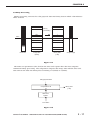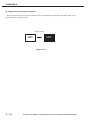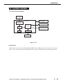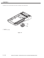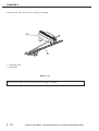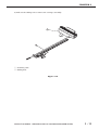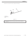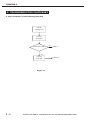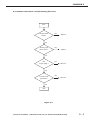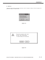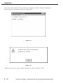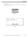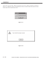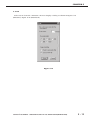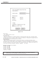
1
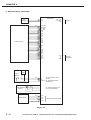
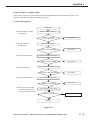
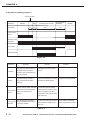
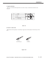
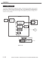
SERVICE
MANUAL
REVISION 0
APR. 2000
JY8-1316-00Z
COPYRIGHT © 2000 CANON INC. CANOSCAN FB1210U REV.0 APR. 2000 PRINTED IN JAPAN (IMPRIME AU JAPON)
COPYRIGHT © 2000 CANON INC.
Printed in Japan
Imprimè au Japon
Use of this manual should be strictly supervised
to avoid disclosure of confidential information.
COPYRIGHT © 2000 CANON INC. CANOSCAN FB1210U REV.0 APR. 2000 PRINTED IN JAPAN (IMPRIME AU JAPON)
LIST OF SERIAL NUMBER
CanoScan FB1210U
F91-4411
F91-4431
F91-4441
F91-4451
F91-4461
F91-4471
F91-4421
F91-4491
AZG000000CZG000000DZG000000EZG000000FZG000000LZG000000MZG000000JZG000000-
COPYRIGHT © 2000 CANON INC. CANOSCAN FB1210U REV.0 APR. 2000 PRINTED IN JAPAN (IMPRIME AU JAPON)
CONTENTS
CHAPTER 1 : GENERAL DESCRIPTIONS
I.
SPECIFICATIONS ....................... 1-1
B. Unlocking the Scanning Unit 1-4
II. PARTS CONFIGURATION ........... 1-2
C. Connecting the Cables ......... 1-5
A. Front View .......................... 1-2
D. Scanning a Document .......... 1-6
B. Rear View ............................ 1-2
IV. CUSTOMER’S DAILY MAINTENANCE
III. SETTING UP THE SCANNER ...... 1-3
........................................... 1-7
A. Precautions ......................... 1-3
CHAPTER 2 : OPERATION AND TIMING
I.
BASIC OPERATION .................... 2-1
F.
A. Functions ............................ 2-1
G. Binary Processing .............. 2-17
B. Electrical System ................ 2-2
H. Image Inversion
(negative/positive) ............ 2-18
C. Main PCB Input and Output . 2-4
D. Basic Sequences of Operations
Averaging .......................... 2-16
IV. CONTROL SYSTEM .................. 2-19
........................................... 2-5
A. Control System Diagram .... 2-19
II. OPTICAL SYSTEM ..................... 2-7
B. Main PCB .......................... 2-19
A. Scanning Lamp .................... 2-8
B. Motor Control ..................... 2-9
III. IMAGE PROCESSING ............... 2-10
A. Outline .............................. 2-10
V.
INTERFACE ............................. 2-20
A. Overview of the USB Standard
......................................... 2-20
B. Benefits of the USB Scanner
B. Image Processing ............... 2-11
......................................... 2-20
C. Calibration ........................ 2-13
C. Signal Definitions .............. 2-21
D. Filter Processing ............... 2-14
D. Interface Connection ......... 2-21
E. Interpolation Processing .... 2-15
VI. POWER SUPPLY ....................... 2-22
COPYRIGHT © 2000 CANON INC. CANOSCAN FB1210U REV.0 APR. 2000 PRINTED IN JAPAN (IMPRIME AU JAPON)
CHAPTER 3 : MECHANICAL SYSTEM
I.
PARTS REPLACEMENT .............. 3-1
A. Removing the Main PCB ...... 3-4
A. Precautions ......................... 3-1
B. Removing the Button PCB ... 3-6
II. EXTERNALS .............................. 3-2
IV. OPTICAL SYSTEM ..................... 3-8
A. Removing the Document Cover
A. Removing the Carriage Assembly
........................................... 3-2
........................................... 3-8
B. Removing the Top Cover and
B. Removing the Motor Assembly
Document Glass Assembly ... 3-3
......................................... 3-14
III. PCBs ......................................... 3-4
CHAPTER 4 : MAINTENANCE AND SERVICING
I.
PERIODICAL REPLACEMENT
III. PERIODICAL SERVICING ........... 4-1
PARTS ....................................... 4-1
IV. SPECIAL TOOLS ........................ 4-1
II. CONSUMABLE PARTS
V.
SOLVENTS AND LUBRICANTS .... 4-1
DURABILITY .............................. 4-1
CHAPTER 5 : TROUBLESHOOTING
I.
INTRODUCTION ......................... 5-1
A. Power LED Not Lighting ....... 5-4
A. Initial Check ....................... 5-1
B. Communication Failure ....... 5-4
B. Others ................................. 5-1
C. Carriage Movement Failure .. 5-5
II. TROUBLESHOOTING FLOWCHART
........................................... 5-2
A. Power ON Failure
Troubleshooting Flowchart .. 5-2
B. Communication Failure
Troubleshooting Flowchart .. 5-3
III. PROBLEM, CAUSE AND
CORRECTIVE ACTION ............... 5-4
D. Poor Image Quality .............. 5-5
E. Noise Generated .................. 5-5
IV. CANON SCANNER TEST ............. 5-6
A. Outline ................................ 5-6
B. Operating Environment ....... 5-6
C. Functions ............................ 5-6
D. Functions Descriptions ....... 5-7
E. Error Message ................... 5-15
CHAPTER 6 : PARTS CATALOG
FIGURE 001 .............................. 6-2
FIGURE 100 .............................. 6-4
COPYRIGHT © 2000 CANON INC. CANOSCAN FB1210U REV.0 APR. 2000 PRINTED IN JAPAN (IMPRIME AU JAPON)
APPENDIX
I.
GENERAL CIRCUIT DIAGRAM .... A-1
II. MAIN PCB CIRCUIT DIAGRAM ... A-2
COPYRIGHT © 2000 CANON INC. CANOSCAN FB1210U REV.0 APR. 2000 PRINTED IN JAPAN (IMPRIME AU JAPON)
CHAPTER 1
GENERAL DESCRIPTIONS
I.
SPECIFICATIONS ....................... 1-1
B. Unlocking the Scanning Unit 1-4
II. PARTS CONFIGURATION ........... 1-2
C. Connecting the Cables ......... 1-5
A. Front View .......................... 1-2
D. Scanning a Document .......... 1-6
B. Rear View ............................ 1-2
IV. CUSTOMER’S DAILY MAINTENANCE
III. SETTING UP THE SCANNER ...... 1-3
........................................... 1-7
A. Precautions ......................... 1-3
COPYRIGHT © 2000 CANON INC.
CANOSCAN FB1210U REV.0 APR. 2000 PRINTED IN JAPAN (IMPRIME AU JAPON)
CHAPTER 1
I. SPECIFICATIONS
Main Unit
Type
: Flatbed image scanner
Reading Unit
Image sensor
Light source
Document type
Document alignment position
Max. document size
Image output mode
:
:
:
:
:
:
Optical resolution
Scanning time
Cropping of scan area
Interface
Interface
Others
Operating environment
Power consumption
Dimensions
Weight
Option
10,550-pixel 3-line CCD
Cold cathode fluorescent lamp
Sheet, Book
Right-end corner
A4/Letter size (216 x 297mm)
Color 14-bit for RGB each
Grayscale (256 gradations)
Binary (black and white)
: 1200 dpi x 2400 dpi
: 7 min. and 10 sec. (color, A4, 1200 dpi)
3 min. (grayscale, A4, 1200 dpi)
7 sec. (binary, A4, 1200 dpi)
: One rectangular area only
: USB (Universal Serial Bus) 1.1
: Temperature : 10 to 35 degrees
Relative humidity : 20 to 80%RH
Air pressure : 608 to 1013 hPa
: 15 W or less (during operation)
8 W (during standby)
: 286.0 (Width) x 461.0 (Depth) x 92.5 (Height) mm
: Approx. 3.8 kg
: Film Adapter Unit FAU-S11
Specifications are subject to change without prior notice.
COPYRIGHT © 2000 CANON INC. CANOSCAN FB1210U REV.0 APR. 2000 PRINTED IN JAPAN (IMPRIME AU JAPON)
1-1
CHAPTER 1
II. PARTS CONFIGURATION
A. Front View
1
2
q DocumentCover
w Document Glass
e Start Button
LTR
A4
B5
B5
R
LT
A4
3
Figure 1-1
B. Rear View
q USB Connector
w Option Connector
e Power Connector
1
2
3
Figure 1-2
1-2
COPYRIGHT © 2000 CANON INC. CANOSCAN FB1210U REV.0 APR. 2000 PRINTED IN JAPAN (IMPRIME AU JAPON)
CHAPTER 1
III. SETTING UP THE SCANNER
A. Precautions
*
*
*
*
*
Keep the scanner out of direct sunlight. Direct exposure to the sun or excessive heat may
cause damage to the scanner.
Do not install the scanner in a humid or dusty environment.
Use the supplied AC adapter only.
Place the scanner securely on an even, flat surface. Tilted or uneven surface may cause a
mechanical problem.
Keep the outer carton and packing material in case you may ship the scanner in the future.
COPYRIGHT © 2000 CANON INC. CANOSCAN FB1210U REV.0 APR. 2000 PRINTED IN JAPAN (IMPRIME AU JAPON)
1-3
CHAPTER 1
B. Unlocking the Scanning Unit
Scanning unit is locked by the carriage lock to prevent a damage during transport. Unlock
the scanning unit by pushing the carriage lock toward the “unlock” mark to use the scanner.
1
LTR
A4
B5
B5
R
LT
A4
q Carriage Lock
Figure 1-3
Note : Ensure to lock the scanning unit during transport.
1-4
COPYRIGHT © 2000 CANON INC. CANOSCAN FB1210U REV.0 APR. 2000 PRINTED IN JAPAN (IMPRIME AU JAPON)
CHAPTER 1
C. Connecting the Cables
FB1210U is connected to the USB port on the host computer. Refer to the “Getting Started”
bundled with the product for details. For connecting the host computer’s cables, refer to the
manuals for the host computer.
1. Connect the AC Adapter Cable and USB Cable
1) Connect the AC adapter plug to the power connector on the scanner.
2) Connect the square plug (B type) of the USB cable to the USB connector on the scanner, and
connect the flat plug (A type) of the USB cable to the USB port on the host computer.
1
2
3
4
q
w
e
r
USB Connector
USB Cable
Power Connector
AC Adapter
Figure 1-4
COPYRIGHT © 2000 CANON INC. CANOSCAN FB1210U REV.0 APR. 2000 PRINTED IN JAPAN (IMPRIME AU JAPON)
1-5
CHAPTER 1
D. Scanning a Document
1) Open the document cover.
2) Place a document on the document glass, facing the image side down and aligning the upper
corner with the alignment mark.
LTR
A4
B5
...XYZ
1
B5
R
LT
A4
q Alignment Mark
Figure 1-5
3) Close the document cover, caring not to dislodge the document.
4) Send “SCAN” command from the host computer to scan.
1-6
COPYRIGHT © 2000 CANON INC. CANOSCAN FB1210U REV.0 APR. 2000 PRINTED IN JAPAN (IMPRIME AU JAPON)
CHAPTER 1
IV. CUSTOMER’S DAILY MAINTENANCE
Dirt on the document glass may cause an unclear image or lines on an image. Clean the
document glass using the following procedures.
1) Disconnect all cables from the scanner.
2) Wipe a dirt off the document glass with a soft clean cloth dampened with water and well
wrung.
3) Thoroughly wipe water off the document glass with a dry cloth.
COPYRIGHT © 2000 CANON INC. CANOSCAN FB1210U REV.0 APR. 2000 PRINTED IN JAPAN (IMPRIME AU JAPON)
1-7
CHAPTER 2
OPERATION AND TIMING
I.
BASIC OPERATION .................... 2-1
F.
Averaging .......................... 2-16
A. Functions ............................ 2-1
G. Binary Processing .............. 2-17
B. Electrical System ................ 2-2
H. Image Inversion
(negative/positive) ............ 2-18
C. Main PCB Input and Output . 2-4
IV. CONTROL SYSTEM ............ 2-19
D. Basic Sequences of Operations
........................................... 2-5
A. Control System Diagram .... 2-19
II. OPTICAL SYSTEM ..................... 2-7
B. Main PCB .......................... 2-19
A. Scanning Lamp .................... 2-8
B. Motor Control ..................... 2-9
III. IMAGE PROCESSING ............... 2-10
A. Outline .............................. 2-10
V.
INTERFACE ............................. 2-20
A. Overview of the USB Standard
......................................... 2-20
B. Benefits of the USB Scanner
B. Image Processing ............... 2-11
......................................... 2-20
C. Calibration ........................ 2-13
C. Signal Definitions .............. 2-21
D. Filter Processing ............... 2-14
D. Interface Connection ......... 2-21
E. Interpolation Processing .... 2-15
VI. POWER SUPPLY ....................... 2-22
COPYRIGHT © 2000 CANON INC.
CANOSCAN FB1210U REV.0 APR. 2000 PRINTED IN JAPAN (IMPRIME AU JAPON)
CHAPTER 2
I. BASIC OPERATION
A. Functions
The scanner functions are divided into the following three main systems.
1. Optical System
The optical system consists of the scanning lamp, lens and mirrors. It exposes a document,
then the reflected light from the document is collected onto a light-sensitive device CCD
(charge-coupled device ) via the lens and mirrors.
2. Image Processing System
The image processing system consists mainly of the CCD, analog IC, and ASIC. It converts
analog signals from the CCD into digital signals, which is read by the host computer.
3. Control System
The control system consists mainly of ASIC, USB controller, CPU, and motor driver. The CPU
controls the whole scanning operation. The USB controller controls the interface between the
CPU and ASIC, while the CPU interprets all commands from the host computer.
Optional Film Adapter Unit FAU S-11
BGR
Scanning
Lamp
B
G
R
Host
CCD
Scanning
Unit
Optical
* System
Lens
Drive
Motor
Computer
Control
Image Processing System
System
Figure 2-1
COPYRIGHT © 2000 CANON INC. CANOSCAN FB1210U REV.0 APR. 2000 PRINTED IN JAPAN (IMPRIME AU JAPON)
2-1
CHAPTER 2
B. Electrical System
1. Outline
The scanner is equipped with CPU and USB controller. Host computer sends a command to
the ASIC via the USB controller and CPU, the CPU controls the whole electrical circuits and
image processing of the scanner. The image signals read by the CCD are converted into digital
data by analog IC. The digital data are then processed by the ASIC and output to the host
computer via USB interface.
Host Computer
USB Interface
USB
Controller
CPU
ROM
SRAM
+12V
AC Adapter
Button PCB
5V
Regulator
Start Button
Power LED
CCD PCB
Analog IC
ASIC
Drive
Motor
Home
Position
Sensor
Motor
Driver
DRAM
Inverter
PCB
Figure 2-2
2-2
COPYRIGHT © 2000 CANON INC. CANOSCAN FB1210U REV.0 APR. 2000 PRINTED IN JAPAN (IMPRIME AU JAPON)
CHAPTER 2
2. Functions of the Main PCB
1) Analog IC
Converts the image signals (analog signals) read by the CCD into digital data.
- CDS (Correlated Double Sampling)
- AGC (Auto Gain Control)
- 14-bit A/D converter (Analog-to-Digital Converter)
2) ASIC
Performs various processing:
- DRAM control
- CCD timing clock creation
- Line buffer control
- CCD output line difference adjustment
- Image processing (Binary processing, Image inversion)
- Shading correction
- Motor driver control
3) DRAM
Stores the shading correction data when performing shading correction, and the image data
when scanning.
4) Motor Driver
A monolithic microstep motor driver supplies power to the drive motor.
5) USB Controller
Transmits data between the host computer and ASIC.
6) CPU
Interprets commands from the host computer to generate parameter for the ASIC to perform
various processing.
COPYRIGHT © 2000 CANON INC. CANOSCAN FB1210U REV.0 APR. 2000 PRINTED IN JAPAN (IMPRIME AU JAPON)
2-3
CHAPTER 2
C. Main PCB Input and Output
AC
Adapter
Scanning Unit
Main PCB
J1-1
-2
JP1-1
-2
-3
-4
-5
-6
-7
-8
-9
-10
-11
-12
-13
-14
-15
-16
-17
-18
-19
-20
-21
-22
-23
-24
-25
-26
-27
-28
+12V
GND
CHK_FAU JP2-1
FAU_LAMP -2
GND -3
LAMP_GND
LAMP_GND
12V_LAMP
12V_LAMP
+15VP
+15VP
DGND
PHI1
DGND
PHI2
DGND
CLB
DGND
DGND
DGND
RB
DGND
TG
VCC
DGND
AGND
AGND
AGND
CCD_B
AGND
CCD_G
AGND
CCD_R
Vbus
DD+
GND
JP4-1
-2
-3
-4
To FAU
To Host
Computer
Power
LED
Start
Button
JP3-1
-2
-3
VCC
LED
HOTKEY0
Button PCB
Home Position
Sensor
"H" when scanning unit
is in home position
JP5-1
-2
Drive Motor
"H" when power LED
is ON
"H" when start button
is pressed
-3
-4
OUT1B
OUT1A
OUT2A
Drive motor drive signal
OUT2B
Figure 2-3
2-4
COPYRIGHT © 2000 CANON INC. CANOSCAN FB1210U REV.0 APR. 2000 PRINTED IN JAPAN (IMPRIME AU JAPON)
CHAPTER 2
D. Basic Sequences of Operations
The basic sequences of operations of CanoScan FB1210U is divided into the power ON
sequence and the document scanning sequence.
1. Power ON Sequence
Power ON
(1) Check Analog IC register
and ASIC port
Execute USB cable test (1)
Connect the scanner.
Power LED is ON?
N
Error returns
Y
(2) Execute Analog IC
read/write test
Execute R/W test (2)
Y
Error returns
Analog IC R/W test failed?
N
(3) Access a fixed address
Execute memory R/W test (3)
Y
Error returns
Memory R/W test failed ?
N
Execute full memory R/W test (4)
(4) Access full memory
Y
Full memory R/W test failed ?
Error returns
N
(5) Access DMA transit test
Execute DMA transit test (5)
Y
Error returns
DMA transit test failed ?
N
(6) Move drive motor forward
100 steps then backward
to check carriage lock on/off
Check carriage lock on/off (6)
N
Carriage lock is off ?
Error returns
Y
Standby
Figure 2-4
COPYRIGHT © 2000 CANON INC. CANOSCAN FB1210U REV.0 APR. 2000 PRINTED IN JAPAN (IMPRIME AU JAPON)
2-5
CHAPTER 2
2. Document Scanning Sequence
Scan Command
Sequence
Standby
Setup
0.1
Time (Sec.)
2.0
Scanning Unit Forward
Scanning Unit
Backward
90.0
Standby
9.0
Home Position
Sensor
Scanning Lamp
ON Signal
Drive Motor
Interface Signal
Figure 2-5
Sequence
Operation
Standby
After the power ON sequence is
completed until the scanner
receives a scan command from
the host computer
To maintain the scanner ready
for scan
Setup
From the scanner receives a
scan command until it starts
scanning
To execute calibration for setting
gain data and shading data
Purpose
Remarks
The data is stored in DRAM
After the scanner starts scanning
until whole scan area specified
Scanning unit
by the host computer are
forward
scanned
To execute image processing
according to the command from
the host computer and send
image data to the host computer
while scanning
After the scanning unit starts
Scanning unit
moving backward until it returns
backward
to the home position
To return the scanning unit to the Home position is detected
home position to ready for the
by the home position sensor
next scan
Table 2-1
2-6
COPYRIGHT © 2000 CANON INC. CANOSCAN FB1210U REV.0 APR. 2000 PRINTED IN JAPAN (IMPRIME AU JAPON)
CHAPTER 2
II. OPTICAL SYSTEM
The optical system has functions from exposing a document by the scanning lamp to
collecting the reflected light to the CCD. The system employs a 3-line CCD to recognize colors
of the document.
CCD
Lens
Scanning Lamp
LTR
A4
B5
B5
R
LT
A4
Figure 2-6
COPYRIGHT © 2000 CANON INC. CANOSCAN FB1210U REV.0 APR. 2000 PRINTED IN JAPAN (IMPRIME AU JAPON)
2-7
CHAPTER 2
A. Scanning Lamp
When the scanner is powered on, the scanning lamp lights to standby. The scanner is
provided with an energy saving setting which is made in the Scanner Utilities Dialog. For
example, if it is set for 30 minutes, then no scan command is sent for 30 minutes, ASIC sends
the scanning lamp off signal to turn off the lamp.
Scanning Lamp
Main PCB
AC
Adapter
PWM
GND
Host
Computer
CPU
CCD
PCB
GND
Inverter
PCB
ASIC
Figure 2-7
2-8
COPYRIGHT © 2000 CANON INC. CANOSCAN FB1210U REV.0 APR. 2000 PRINTED IN JAPAN (IMPRIME AU JAPON)
CHAPTER 2
B. Motor Control
When the host computer sends a command to change scaling/resolution, the motor driver
current control signals [PA+, PA-, PB+, PB-] are changed to generate a torque for the rotating
speed. Yet, the reverse speed of the scanning unit is always constant.
The ASIC receives each command sent from the host computer via the USB interface to
control the motor by four-phase motor driver pulse signals [OUT1B, OUT1A, OUT2A, OUT2B].
Main PCB
OUT1B
PA+
PAHost
Computer
ASIC
PB+
Motor
Driver
PB-
OUT1A
OUT2A
Drive
Motor
OUT2B
Figure 2-8
COPYRIGHT © 2000 CANON INC. CANOSCAN FB1210U REV.0 APR. 2000 PRINTED IN JAPAN (IMPRIME AU JAPON)
2-9
CHAPTER 2
III. IMAGE PROCESSING
A. Outline
The image processing system converts light signals read by the CCD to electric signals, then
outputs the image data to the host computer via the USB interface upon various image
processing.
SRAM
CPU
ROM
Clock
DRAM
Control
Signal
Control Signal
USB Connector
D+
Clock
USB
Controller
USB
Data
Data
Control Signal
ASIC
Analog IC
Vin
CCD
Data
DStatus Signal
Control Clock
Motor
Driver
Inverter
Home Position
Sensor
Scanning Lamp
Drive Motor
Figure 2-9
2 - 10
COPYRIGHT © 2000 CANON INC. CANOSCAN FB1210U REV.0 APR. 2000 PRINTED IN JAPAN (IMPRIME AU JAPON)
CHAPTER 2
B. Image Processing
1. Analog IC
Output signal from the CCD is an analog signal which cannot be used as image data. So
RGB output signal from the CCD is amplified by analog amplifier to generate analog data. The
generated data is converted into averaged analog signal by D/A converter, then got feedback to
the A/D converter to output constant digital data to the ASIC.
D/A Converter
CCD
R
G
B
Analog
Amplifier
A/D Converter
Digital data
To ASIC
Analog IC
Figure 2-10
COPYRIGHT © 2000 CANON INC. CANOSCAN FB1210U REV.0 APR. 2000 PRINTED IN JAPAN (IMPRIME AU JAPON)
2 - 11
CHAPTER 2
2. D/A Converter
D/A converter removes ununiform analog data generated by the CCD. It adjusts CCD output
to keep max. 5V of input signal to the A/D converter, to make the black level of the image
constant.
3. A/D Converter
The A/D converter converts the black-level-corrected image signal (analog signal) to a 14-bit
image data (digital signal) in the order of red, green and blue image signal.
5V is applied to the VRT terminal and reference voltage is applied to the VRB terminal. A/D
converter outputs “0” when input signal is 5V, and outputs “16383” when input signal is
reference voltage. This converts 1 pixel signal into the image data of 16384 gradations for red,
green and blue each.
Image Data
A/D Converter
Blue Image Signal
Green Image Signal
Red Image Signal
B
G
R
Output
Reference Voltage
+5V
V
OFFSET
0
0
0
0
0
0
0
0
0
0
0
0
0
0
1
1
1
1
1
1
1
1
1
1
1
1
1
1
Figure 2-11
2 - 12
COPYRIGHT © 2000 CANON INC. CANOSCAN FB1210U REV.0 APR. 2000 PRINTED IN JAPAN (IMPRIME AU JAPON)
CHAPTER 2
C. Calibration
Calibration can be performed to normalize the pixels of a linear CCD so that each pixel
produces the same digital output code from the scanner when presented with the same image
light intensity. This intensity ranges from black (no light) to white (maximum light intensity).
The CCD’s analog output may have large pixel-to-pixel variations in their output voltage when
scanning the same white image (corresponding to errors on brighter signals). If these offsets
are subtracted from each pixel, and each pixel is given the optimum gain setting to correct for
different efficiencies, then these errors can be eliminated.
Ideally the digital output code for any pixel would be zero for a black image, and some code
near the full scale for an image with maximum brightness. This code is called the target code.
The analog IC eliminates these global and pixel-to-pixel offset and gain errors with its
Correlated Double Sampling, Offset D/A converter, Variable Gain Amplifier (VGA), and
Programmable Gain Amplifier (PGA).
Calibrating an analog IC-based system requires three steps:
1) Offset Calibration
Takes a black image and normalizes the digital output code for each pixel to a code at or near
0.
2) Boot-Gain/Coarse-Gain Stage Calibration
Finds the optimum gain setting that places the output voltage of all the pixels from x0.93 to
x9 adjustment range of these two stages.
3) Shading Correction from ASIC
Calculates the gain required for normalizing the output of each pixel to the target code.
COPYRIGHT © 2000 CANON INC. CANOSCAN FB1210U REV.0 APR. 2000 PRINTED IN JAPAN (IMPRIME AU JAPON)
2 - 13
CHAPTER 2
D. Filter Processing
When converting resolution and scaling, the image quality tends to be reduced. To prevent
the image quality reduction, filter processing is performed according to the resolution. Filter
processing for this scanner includes horizontal scanning interpolation, vertical scanning
interpolation, descreen, and averaging. Table 2-2 shows the resolution for filter processing.
Gradation
Color
Grayscale
Vertical
scanning
interpolation
Descreen
Averaging
10-99
Horizontal
scanning
interpolation
x
x
o
x
100
x
o
o
x
101-149
x
x
o
x
150
x
o
o
x
151-299
o
x
o
o
300
x
o
x
x
301-1200
o
x
x
x
10-149
x
x
o
x
Resolution
(dpi)
150
o
x
o
x
151-299
o
x
o
o
300
x
x
x
x
301-1200
o
x
x
x
Table 2-2
2 - 14
COPYRIGHT © 2000 CANON INC. CANOSCAN FB1210U REV.0 APR. 2000 PRINTED IN JAPAN (IMPRIME AU JAPON)
CHAPTER 2
E. Interpolation Processing
When reading images at higher resolution, the one pixel output of the CCD is treated as two
image data in the horizontal scanning direction, and the one line output of the CCD is treated
as two image data in the vertical scanning direction, causing a reduced image quality. To
prevent the image quality reduction, interpolation processing is performed. Figure 2-12 shows
a change in image density by the interpolation processing.
A
(A)
B
(B)
C
(C)
D
Interpolation processing
A
(A+B)/2
B
(B+C)/2
C
(C+D)/2
D
Image
Density
1 pixel
Interpolation processing
Image
Density
1 pixel
Figure 2-12
COPYRIGHT © 2000 CANON INC. CANOSCAN FB1210U REV.0 APR. 2000 PRINTED IN JAPAN (IMPRIME AU JAPON)
2 - 15
CHAPTER 2
F. Averaging
When reading images at lower resolution, the thinned data increases resulting in output
image deterioration. Averaging is a process in which the data to be thinned and the data to be
actually output are averaged and output, in order to suppress the image deterioration due to
the data thinning.
CCD
reading
data
A
B
C
D
E
F
G
H
A
B
C
D
E
F
G
H
B
C
D
E
F
G
H
Output
image
data
Thinned data
CCD
reading
data
Output
image
data
A
A'
E'
Averaged data=(A+B+C+D)/4
Figure 2-13
2 - 16
COPYRIGHT © 2000 CANON INC. CANOSCAN FB1210U REV.0 APR. 2000 PRINTED IN JAPAN (IMPRIME AU JAPON)
CHAPTER 2
G. Binary Processing
Binary processing converts the 8-bit grayscale data into binary data in which 1 bit indicates
white or black.
255
254
.
.
.
129
128
127
126
.
.
.
1
0
Slice
level
Document
Binary
processing
Image data
(8 bits)
1
1
.
.
.
1
1
0
0
.
.
.
0
0
Binary data
(1 bit)
Output image
Figure 2-14
The ASIC sets parameters (slice level) in the slice level register when the host computer
commands binary processing. The comparator compares the image data with the slice level,
and converts the data into binary data consisting of 1 (black) or 0 (white).
8 bit grayscale data
A
Comparator A>B
B
Binary data
(1 bit)
Slice level
register
From ASIC
Figure 2-15
COPYRIGHT © 2000 CANON INC. CANOSCAN FB1210U REV.0 APR. 2000 PRINTED IN JAPAN (IMPRIME AU JAPON)
2 - 17
CHAPTER 2
H. Image Inversion (negative/positive)
Image inversion is to reverse the density level of a document by inverting the color data, 8-bit
grayscale data or binary data.
Image Inversion
ABC
ABC
Document
Image Output
Figure 2-16
2 - 18
COPYRIGHT © 2000 CANON INC. CANOSCAN FB1210U REV.0 APR. 2000 PRINTED IN JAPAN (IMPRIME AU JAPON)
CHAPTER 2
IV. CONTROL SYSTEM
A. Control System Diagram
Host
Computer
Main PCB
+12V
USB
Controller
AC Adapter
Scanning Unit
ASIC
CPU
Inverter &
Scanning Lamp
ROM
Motor Driver
Drive Motor
Figure 2-17
B. Main PCB
Main PCB consists of CPU, ROM, SRAM, DRAM, ASIC, USB controller, analog I/C and motor
driver. The CPU controls all scanning operations, and the ROM has the control program code.
COPYRIGHT © 2000 CANON INC. CANOSCAN FB1210U REV.0 APR. 2000 PRINTED IN JAPAN (IMPRIME AU JAPON)
2 - 19
CHAPTER 2
V. INTERFACE
A. Overview of the USB Standard
Since early 1997, the Universal Serial Bus (USB) has been the standard on most PCs. The
USB standard was developed by Compaq, IBM, Intel, Microsoft, NEC, and Northern Telecom. It
resulted from an industry-wide initiative to standardize peripheral attachments to PCs, and to
improve the speed, performance and ease of use of PC peripherals.
USB has been supported from Windows 95 (OSR 2.1), and it is now a key component of
Windows 98. In addition, USB are supported in Windows CE and Windows 2000 according to
Microsoft. USB support is currently available on the Apple platform and will be available
shortly on some other platforms.
B. Benefits of the USB Scanner
1. True Plug & Play
Unlike the previous generation of SCSI scanners, no add-in cards are required to setup the
USB scanners. This eliminates complex procedures, such as opening the box to install a card,
or reconfiguring the system (setting DMA, IRQ, jumper cables, etc.) The USB scanners are
simply plugged in and unplugged at any time.
2. Higher Speed
USB scanner is nearly 10 times faster than a standard parallel-port scanner at bandwidth 12
Mbits/sec.
3. Multiple Devices Support
USB specification can support up to 127 devices simultaneously on a computer by using
“hub” terminals as additional plug-in locations.
2 - 20
COPYRIGHT © 2000 CANON INC. CANOSCAN FB1210U REV.0 APR. 2000 PRINTED IN JAPAN (IMPRIME AU JAPON)
CHAPTER 2
C. Signal Definitions
USB uses two differential signal lines (D+ and D-) only to communicate with the host
computer.
Pin
Signal
1
2
3
VBUS
4
Signal GND
Shell
Chassis
DD+
2
3
1
4
Chassis GND
Table 2-3
D. Interface Connection
USB connctor has A plug for connecting to upper layer and B plug for connecting to lower
layer.
A Plug
To Host Computer
B Plug
To Scanner
Figure 2-18
COPYRIGHT © 2000 CANON INC. CANOSCAN FB1210U REV.0 APR. 2000 PRINTED IN JAPAN (IMPRIME AU JAPON)
2 - 21
CHAPTER 2
VI. POWER SUPPLY
DC power is supplied from a supplied AC adapter. Through power regulator, three DC power
sources (+5V, +12V and +15V) are used in the circuit. +5V is supplied for the digital circuit
and linear chip, +15V is for the CCD PCB, and +12V is for the motor driver and scanning lamp.
Protection circuit is used between the AC adapter and regulator to prevent over voltage, over
current or reverse polarity.
Main PCB
12V
AC Adapter
Protection
Circuit
CCD PCB
12V
15V to 12V
Linear
Regulator
12V to 15V
Step up switching
Regulator
12V to 5V
Linear
Regulator
CCD
Analog IC
Drive
Motor
Motor Driver
PWM
PWM
Inverter
Inverter
Scanning Lamp
FAU Lamp
x2
FAU-S11
Figure 2-19
2 - 22
COPYRIGHT © 2000 CANON INC. CANOSCAN FB1210U REV.0 APR. 2000 PRINTED IN JAPAN (IMPRIME AU JAPON)
CHAPTER 3
MECHANICAL SYSTEM
I.
PARTS REPLACEMENT .............. 3-1
A. Removing the Main PCB ...... 3-4
A. Precautions ......................... 3-1
B. Removing the Button PCB ... 3-6
II. EXTERNALS .............................. 3-2
IV. OPTICAL SYSTEM ..................... 3-8
A. Removing the Document Cover
........................................... 3-2
B. Removing the Top Cover and
Document Glass Assembly ... 3-3
A. Removing the Carriage Assembly
........................................... 3-8
B. Removing the Motor Assembly
......................................... 3-14
III. PCBs ......................................... 3-4
COPYRIGHT © 2000 CANON INC.
CANOSCAN FB1210U REV.0 APR. 2000 PRINTED IN JAPAN (IMPRIME AU JAPON)
CHAPTER 3
I. PARTS REPLACEMENT
A. Precautions
* Disconnect the AC adapter and USB cable from the scanner before replacing the parts.
* Wear anti-static gloves and grounding strap around the wrist during the work.
* Follow the instructed steps. Do not loosen any screw from the parts that is not to be
replaced.
* Store the removed parts in a clean place and avoid missing.
* Attach the parts in reverse order of the removing steps, unless otherwise specified.
* After replacement, check the quantity and shape of the parts.
COPYRIGHT © 2000 CANON INC. CANOSCAN FB1210U REV.0 APR. 2000 PRINTED IN JAPAN (IMPRIME AU JAPON)
3-1
CHAPTER 3
II. EXTERNALS
A. Removing the Document Cover
1) Open the document cover until it is perpendicular to the base frame, then lift to remove it.
1
LTR
A4
B5
2
B5
R
LT
A4
q Document Cover
w Base Frame
Figure 3-1
3-2
COPYRIGHT © 2000 CANON INC. CANOSCAN FB1210U REV.0 APR. 2000 PRINTED IN JAPAN (IMPRIME AU JAPON)
CHAPTER 3
B. Removing the Top Cover and Document Glass Assembly
1) Remove two screws from the top cover, then lift the top cover and document glass assembly
to remove them.
1
2
3
LT
R
A4
B5
5
B
R
LT
4
A
q Screw
w Top Cover
e Document Glass Assembly
Figure 3-2
COPYRIGHT © 2000 CANON INC. CANOSCAN FB1210U REV.0 APR. 2000 PRINTED IN JAPAN (IMPRIME AU JAPON)
3-3
CHAPTER 3
III. PCBs
A. Removing the Main PCB
1) Remove three screws from the bottom of the scanner to take out the main PCB.
1
2
q Screw
w Main PCB
Figure 3-3
3-4
COPYRIGHT © 2000 CANON INC. CANOSCAN FB1210U REV.0 APR. 2000 PRINTED IN JAPAN (IMPRIME AU JAPON)
CHAPTER 3
2) Disconnect the cables for the motor assembly, button PCB and scanning unit from the main
PCB.
1
2
3
q Motor Assembly Cable
w Button PCB Cable
e Scanning Unit Cable (Flat Cable)
Figure 3-4
COPYRIGHT © 2000 CANON INC. CANOSCAN FB1210U REV.0 APR. 2000 PRINTED IN JAPAN (IMPRIME AU JAPON)
3-5
CHAPTER 3
B. Removing the Button PCB
1) Remove the main PCB.
2) Remove the top cover and document glass assembly.
3) Remove two screws from the cable cover to remove it, then cut four tie-wraps.
1
2
3
q Screw
w Cable Cover
e Tie-wrap
Figure 3-5
3-6
COPYRIGHT © 2000 CANON INC. CANOSCAN FB1210U REV.0 APR. 2000 PRINTED IN JAPAN (IMPRIME AU JAPON)
CHAPTER 3
4) Remove the screw from the button PCB to remove it.
1
2
q Screw
w Button PCB
Figure 3-6
Note: When assembling, make sure to tie-wrap the cables for the motor assembly and
button PCB.
COPYRIGHT © 2000 CANON INC. CANOSCAN FB1210U REV.0 APR. 2000 PRINTED IN JAPAN (IMPRIME AU JAPON)
3-7
CHAPTER 3
IV. OPTICAL SYSTEM
A. Removing the Carriage Assembly
1) Remove the main PCB.
2) Remove the top cover and document glass assembly.
3) Rotate the gear mounted on the motor assembly to move the carriage assembly away from
the home position.
1
2
3
q Scanning Unit
w Motor Assembly
e Gear
Figure 3-7
3-8
COPYRIGHT © 2000 CANON INC. CANOSCAN FB1210U REV.0 APR. 2000 PRINTED IN JAPAN (IMPRIME AU JAPON)
CHAPTER 3
4) Remove two screws that fix the gear plate 2 on the sliding rod to remove the gear plate 2 and
spring.
1
2
3
4
q
w
e
r
Screw
Gear Plate 2
Spring
Sliding Rod
Figure 3-8
Note: When fixing the gear plate 2 on the sliding rod, use the spring to adjust the drive belt
tension.
COPYRIGHT © 2000 CANON INC. CANOSCAN FB1210U REV.0 APR. 2000 PRINTED IN JAPAN (IMPRIME AU JAPON)
3-9
CHAPTER 3
5) Remove the screw that fixes the motor assembly on the main frame.
1
2
q Screw
w Motor Assembly
Figure 3-9
3 - 10
COPYRIGHT © 2000 CANON INC. CANOSCAN FB1210U REV.0 APR. 2000 PRINTED IN JAPAN (IMPRIME AU JAPON)
CHAPTER 3
6) Slide the sliding rod with the carriage assembly in the arrow direction, then lift to remove it.
1
2
q Scanning Unit
w Sliding Rod
Figure 3-10
COPYRIGHT © 2000 CANON INC. CANOSCAN FB1210U REV.0 APR. 2000 PRINTED IN JAPAN (IMPRIME AU JAPON)
3 - 11
CHAPTER 3
7) Remove the drive belt from the carriage assembly.
1
2
q Scanning Unit
w Drive Belt
Figure 3-11
Note: Do not remove the flat cable from the carriage assembly.
3 - 12
COPYRIGHT © 2000 CANON INC. CANOSCAN FB1210U REV.0 APR. 2000 PRINTED IN JAPAN (IMPRIME AU JAPON)
CHAPTER 3
8) Pull out the sliding rod to remove the carriage assembly.
1
2
q Scanning Unit
w Sliding Rod
Figure 3-12
COPYRIGHT © 2000 CANON INC. CANOSCAN FB1210U REV.0 APR. 2000 PRINTED IN JAPAN (IMPRIME AU JAPON)
3 - 13
CHAPTER 3
B. Removing the Motor Assembly
1)
2)
3)
4)
5)
Remove
Remove
Remove
Remove
Pull the
the main PCB.
the top cover and document glass assembly.
the carriage assembly.
two screws from the cable cover to remove it, then cut four tie-wraps.
drive belt through the gear to remove it from the motor assembly.
1
3
2
q Drive Belt
w Motor Assembly
e Gear
Figure 3-13
3 - 14
COPYRIGHT © 2000 CANON INC. CANOSCAN FB1210U REV.0 APR. 2000 PRINTED IN JAPAN (IMPRIME AU JAPON)
CHAPTER 3
6) Remove the screw that fixes the motor assembly on the sliding rod.
1
2
3
q Sliding Rod
w Motor Assembly
e Screw
Figure 3-14
Note: When attaching, make sure to tie-wrap the cables for the motor assembly and
button PCB.
COPYRIGHT © 2000 CANON INC. CANOSCAN FB1210U REV.0 APR. 2000 PRINTED IN JAPAN (IMPRIME AU JAPON)
3 - 15
CHAPTER 4
MAINTENANCE AND SERVICING
I.
PERIODICAL REPLACEMENT
III. PERIODICAL SERVICING ........... 4-1
PARTS ....................................... 4-1
IV. SPECIAL TOOLS ........................ 4-1
II. CONSUMABLE PARTS
V.
SOLVENTS AND LUBRICANTS .... 4-1
DURABILITY .............................. 4-1
COPYRIGHT © 2000 CANON INC.
CANOSCAN FB1210U REV.0 APR. 2000 PRINTED IN JAPAN (IMPRIME AU JAPON)
CHAPTER 4
I. PERIODICAL REPLACEMENT PARTS
None
II. CONSUMABLE PARTS DURABILITY
None
III. PERIODICAL SERVICING
None
IV. SPECIAL TOOLS
None
V. SOLVENTS AND LUBRICANTS
None
COPYRIGHT © 2000 CANON INC. CANOSCAN FB1210U REV.0 APR. 2000 PRINTED IN JAPAN (IMPRIME AU JAPON)
4-1
CHAPTER 5
TROUBLESHOOTING
I.
INTRODUCTION ......................... 5-1
A. Power LED Not Lighting ....... 5-4
A. Initial Check ....................... 5-1
B. Communication Failure ....... 5-4
B. Others ................................. 5-1
C. Carriage Movement Failure .. 5-5
II. TROUBLESHOOTING FLOWCHART
........................................... 5-2
A. Power ON Failure
Troubleshooting Flowchart .. 5-2
B. Communication Failure
Troubleshooting Flowchart .. 5-3
III. PROBLEM, CAUSE AND
CORRECTIVE ACTION ............... 5-4
COPYRIGHT © 2000 CANON INC.
D. Poor Image Quality .............. 5-5
E. Noise Generated .................. 5-5
IV. CANON SCANNER TEST ............. 5-6
A. Outline ................................ 5-6
B. Operating Environment ....... 5-6
C. Functions ............................ 5-6
D. Functions Descriptions ....... 5-7
E. Error Message ................... 5-15
CANOSCAN FB1210U REV.0 APR. 2000 PRINTED IN JAPAN (IMPRIME AU JAPON)
CHAPTER 5
I. INTRODUCTION
A. Initial Check
Check if the operating environment conforms to the following conditions.
*
*
*
*
*
Line voltage is within ±10% of the rated value.
Ambient temperature and humidity conform to the operating environment. (Refer to
CHAPTER 1, I. SPECIFICATIONS)
The scanner is not setup near a water faucet, boiler, humidifier, open flame, or in dusty
place.
The scanner is not exposed to direct sunlight. If it is inevitable to setup in a sunny place,
hang a curtain to block direct sunlight.
The scanner is setup in a well-ventilated place.
B. Others
Moving a scanner from a cold place to a warm place can cause condensation on the metal
parts, resulting in a faulty operation.
COPYRIGHT © 2000 CANON INC. CANOSCAN FB1210U REV.0 APR. 2000 PRINTED IN JAPAN (IMPRIME AU JAPON)
5-1
CHAPTER 5
II. TROUBLESHOOTING FLOWCHART
A. Power ON Failure Troubleshooting Flowchart
Unlock
Carriage Lock
Connect
AC Adapter
No
Power LED is ON ?
Table 5-1
Yes
Connect
USB cable
Figure 5-2
Figure 5-1
5-2
COPYRIGHT © 2000 CANON INC. CANOSCAN FB1210U REV.0 APR. 2000 PRINTED IN JAPAN (IMPRIME AU JAPON)
CHAPTER 5
B. Communication Failure Troubleshooting Flowchart
Scan
Communication
failed ?
Yes
Table 5-2
No
Scanning Unit
cannot move ?
Yes
Table 5-3
No
Poor
image quality ?
Yes
Table 5-4
No
Acoustic noise
generated ?
Yes
Table 5-5
No
End
Figure 5-2
COPYRIGHT © 2000 CANON INC. CANOSCAN FB1210U REV.0 APR. 2000 PRINTED IN JAPAN (IMPRIME AU JAPON)
5-3
CHAPTER 5
III. PROBLEM, CAUSE AND CORRECTIVE ACTION
FB1210U may have the following five problems.
*
*
*
*
*
Power LED not lighting
Communication failure
Carriage movement failure
Poor image quality
Noise generated
A. Power LED Not Lighting
Possible Cause
AC adapter is unplugged
Related Parts
Check Method
None
Visual check
Corrective Action
Plug the AC adapter into
the outlet
from the outlet
AC Adapter cable is
Visual check
None
Connect the AC adapter cable
to the power connector on the
disconnected from the scanner
scanner
AC adapter output voltage
AC Adapter
failure
Output voltage Replace the AC adapter
(+12V) check
Main PCB failure
Main PCB
Tester check
Replace the main PCB
(+12V, GND)
Main PCB connection failure
Visual check
None
Properly connect the main PCB
Table 5-1
B. Communication Failure
Possible Cause
USB cable connection failure
Related Parts
USB cable
Check Method
Visual check
Corrective Action
Connect the USB cable
properly
Scanner communication failure
Main PCB
Trial replacement Replace the main PCB
Scanning unit failure
Scanning unit
Trial replacement Replace the scanning unit
Table 5-2
5-4
COPYRIGHT © 2000 CANON INC. CANOSCAN FB1210U REV.0 APR. 2000 PRINTED IN JAPAN (IMPRIME AU JAPON)
CHAPTER 5
C. Carriage Movement Failure
Drive belt broken or worn
Possible Cause
Drive belt
Releated Parts
Check Method
Corrective Action
Trial replacement Replace the drive belt
Gears broken or worn
Gear plate 2
Trial replacement Replace the gear plate 2
Start button failure
Button PCB
Trial replacement Replace the button PCB
Drive motor failure
Motor assembly Trial replacement Replace the motor assembly
Table 5-3
D. Poor Image Quality
Scanning lamp is dark
Releated Parts Check Method
Visual check
Scanning unit
Dirt on document glass
Document glass Visual check
Main PCB failure
Main PCB
CCD PCB failure
Scanning unit
Possible Cause
Corrective Action
Replace the scanning unit
Clean the document glass
Trial replacement Replace the main PCB
Trial replacement Replace the scanning unit
Table 5-4
E. Noise Generated
Possible Cause
Related Parts
Check Method
Corrective Action
Motor assembly failure
Main PCB failure
Scanning unit failure
Dirt on sliding rod
Motor assembly
Main PCB
Scanning unit
None
Document glass
Trial replacement
Trial replacement
Trial replacement
Visual check
Trial replacement
Replace the motor assembly
Replace the main PCB
Replace the scanning unit
Clean the sliding rod
Replace the document glass
Reference sheet is
improperly positioned
Table 5-5
COPYRIGHT © 2000 CANON INC. CANOSCAN FB1210U REV.0 APR. 2000 PRINTED IN JAPAN (IMPRIME AU JAPON)
5-5
CHAPTER 5
IV. CANON SCANNER TEST
A. Outline
Canon Scanner Test is a utility software to check if faulty operation of CanoScan FB1210U is
due to the hardware or the communication with the host computer.
Windows : chk1210.exe (English or Japanese is switched according to the language to be used
in Windows.)
Macintosh : chk_for_1210U_E
B. Operating Environment
The following environment is required for operating the Canon Scanner Test.
Windows platform
* CanoScan FB1210U
* PC/AT Compatibles (Pentium or later)
* Windows 98 OS or Windows 2000 OS
* FB1210U Device Driver
Macintosh platform
* CanoScan FB1210U
* Power Macintosh
* Macintosh OS (Version 8.5 or later)
* FB1210U Device Driver
Note: Install CanoScan FB1210U device driver before using the Canon Scanner Test.
C. Functions
Canon Scanner Test has the following functions.
1. Scanner Information
CanoScan FB1210U ROM version, etc. are shown when the scanner is properly
communicated with the host computer.
2. Self Test
CanoScan FB1210U self test is executed.
3. Save Test Data
Test result text data is saved in the folder of the Canon Scanner Test.
4. Scan
An image is scanned and saved as an image file.
5-6
COPYRIGHT © 2000 CANON INC. CANOSCAN FB1210U REV.0 APR. 2000 PRINTED IN JAPAN (IMPRIME AU JAPON)
CHAPTER 5
D. Functions Descriptions
1. Scanner Information
Select “Scanner information” from the “Function” menu to display as shown in Figure 5-3
(Windows), Figure 5-4 (Macintosh).
Figure 5-3
Figure 5-4
COPYRIGHT © 2000 CANON INC. CANOSCAN FB1210U REV.0 APR. 2000 PRINTED IN JAPAN (IMPRIME AU JAPON)
5-7
CHAPTER 5
* Vendor ID
CanoScan FB1210U manufacturer name as “Canon”
* Product ID
Product name of CanoScan FB1210U as “IX-12025G”
* ROM Version
Firmware version of CanoScan FB1210U
* USB Port
USB information (Windows only)
5-8
COPYRIGHT © 2000 CANON INC. CANOSCAN FB1210U REV.0 APR. 2000 PRINTED IN JAPAN (IMPRIME AU JAPON)
CHAPTER 5
2. Self Test
Select “Scanner self test” from the “Function” menu to display a dialog as shown in Figure 5-5
(Windows), Figure 5-6 (Macintosh).
Figure 5-5
Figure 5-6
COPYRIGHT © 2000 CANON INC. CANOSCAN FB1210U REV.0 APR. 2000 PRINTED IN JAPAN (IMPRIME AU JAPON)
5-9
CHAPTER 5
Click “OK” to start scanner self test. When it is completed normally, a dialog is displayed as
shown in Figure 5-7 (Windows), Figure 5-8 (Macintosh).
Figure 5-7
Figure 5-8
When an error occurs, refer to “E. Error Message” to take a corrective action.
5 - 10
COPYRIGHT © 2000 CANON INC. CANOSCAN FB1210U REV.0 APR. 2000 PRINTED IN JAPAN (IMPRIME AU JAPON)
CHAPTER 5
3. Save Test Data
Select “Save test data” from the “Function” menu to display a dialog as shown in Figure 5-9
(Windows), Figure 5-10 (Macintosh).
Figure 5-9
Figure 5-10
COPYRIGHT © 2000 CANON INC. CANOSCAN FB1210U REV.0 APR. 2000 PRINTED IN JAPAN (IMPRIME AU JAPON)
5 - 11
CHAPTER 5
Click “OK” to save test data. When test data has been saved, a dialog is displayed as shown in
Figure 5-11 (Windows), Figure 5-12 (Macintosh), and test result text data (test_dat.txt) is saved
in the folder of the Canon Scanner Test.
Figure 5-11
Figure 5-12
5 - 12
COPYRIGHT © 2000 CANON INC. CANOSCAN FB1210U REV.0 APR. 2000 PRINTED IN JAPAN (IMPRIME AU JAPON)
CHAPTER 5
4. Scan
Select “Scan” from the “Function” menu to display a dialog as shown in Figure 5-13
(Windows), Figure 5-14 (Macintosh).
Figure 5-13
COPYRIGHT © 2000 CANON INC. CANOSCAN FB1210U REV.0 APR. 2000 PRINTED IN JAPAN (IMPRIME AU JAPON)
5 - 13
CHAPTER 5
Figure 5-14
* Scan count
Set a number from 1 to 100.
* Resolution (dpi)
When the resolution for scanning an image is selected at 200, 300, 400, or 600 dpi, whole
document glass area is scanned. When selected at 1200 dpi, 10,280 pixel x 500 pixel area in
the upper side of the document glass is scanned.
* Image handling
When “Read in memory (no file)” is selected, the image is read into the memory, then
abandoned after readout. When “Save to TIFF file” is selected for handling an scanned image,
the file of “img0.tif” is saved in the folder of the Canon Scanner Test. When scan count is set
at 2 or more, the file of “img0.tif”, “img1.tif”, “img2.tif” ... are saved.
File space to be saved is as follows.
200 dpi : 11.3 MB
300 dpi : 25.6 MB
400 dpi : 45.5 MB
600 dpi : 102.4 MB
1200 dpi : 14.6 MB
Note : Confirm before scanning that the available disk space on the HDD in which the
Canon Scanner Test is installed exceeds above file space.
5 - 14
COPYRIGHT © 2000 CANON INC. CANOSCAN FB1210U REV.0 APR. 2000 PRINTED IN JAPAN (IMPRIME AU JAPON)
CHAPTER 5
E. Error Message
1. “Scanner is disconnected or locked.”
Cause 1 : Carriage lock is locked.
Corrective action : Unlock the carriage lock.
Cause 2 : USB cable is not properly connected.
Corrective action : Connect the USB cable to the host computer and the scanner properly.
Cause 3 : Scanner is not detected by the host computer.
Corrective action : Refer to the “II. Troubleshooting Flowchart”.
2. “Scanner is disconnected.”
Cause 1 : Scanner is not connected to the host computer.
Corrective action : Refer to the “II. Troubleshooting Flowchart”.
Cause 2 : Device driver is not installed.
Corrective action : Install FB1210U device driver.
3. “Insupportable scanner is connected.”
Cause : The connected scanner is not supported by the Canon Scanner Test.
Corrective Action : Connect CanoScan FB1210U.
4. “Unable to find the scanner. Check if the cables are connected properly.”
Cause : Scanner is not detected by the host computer.
Corrective Action : Refer to the “II. Troubleshooting Flowchart”.
5. “Failed to read scanner information.”
Cause : Scanner is not detected by the host computer.
Corrective Action : Refer to the “II. Troubleshooting Flowchart”.
6. “Failed to create a file.” “Failed to open a file.” “Failed to close a file.” “Failed to
write-in a file.”
Cause : Canon Scanner Test is started from a CD-ROM or write-protected HDD.
Corrective Action : Copy the Canon Scanner Test on a writable HDD to use.
7. “Unable to communicate with scanner. Check if scanner is powered ON or USB cable
is connected properly.”
Cause : Scanner is not detected by the host computer.
Corrective Action : Refer to the “II. Troubleshooting Flowchart”.
8. “Scanner has problem.” “Failed to execute scanner self test.”
Cause : Scanner is not detected by the host computer.
Corrective Action : Refer to the “II. Troubleshooting Flowchart”.
9. “Failed to allocate memory.”
Cause : Scanner is not detected by the host computer.
Corrective Action : Refer to the “II. Troubleshooting Flowchart”.
COPYRIGHT © 2000 CANON INC. CANOSCAN FB1210U REV.0 APR. 2000 PRINTED IN JAPAN (IMPRIME AU JAPON)
5 - 15
CHAPTER 6
PARTS CATALOG
FIGURE 001 .............................. 6-2
COPYRIGHT © 2000 CANON INC.
FIGURE 100 .............................. 6-4
CANOSCAN FB1210U REV.0 APR. 2000 PRINTED IN JAPAN (IMPRIME AU JAPON)
CanoScan FB1210U
COPYRIGHT © 2000 CANON INC.
CANOSCAN FB1210U REV.0 APR. 2000 PRINTED IN JAPAN (IMPRIME AU JAPON)
6-1
FIGURE 001
ACCESSORY
1
2
3
4
5
6-2
COPYRIGHT © 2000 CANON INC.
CANOSCAN FB1210U REV.0 APR. 2000 PRINTED IN JAPAN (IMPRIME AU JAPON)
R
A
N
K
Q'
T
Y
FIGURE
&
KEY NO.
PART NUMBER
001-01
NIC-BXDC-000
1
CABLE, INTERFACE
02
NIP-WFS0-722
1
ADAPTOR, AC
CANADA, LA, USA
NIP-WFS0-723
1
ADAPTOR, AC
JAPAN
03
NIP-WFS0-724
1
ADAPTOR, AC
EUR
04
NIP-WFS0-725
1
ADAPTOR, AC
UK, HK
05
NIP-WFS0-726
1
ADAPTOR, AC
AUSTRALIA, SINGAPORE
COPYRIGHT © 2000 CANON INC.
DESCRIPTION
SERIAL NUMBER/REMARKS
CANOSCAN FB1210U REV.0 APR. 2000 PRINTED IN JAPAN (IMPRIME AU JAPON)
6-3
FB1210U
FIGURE 100
1
2
3
LTR
A4
B5
5
4
B5
R
LT
6
A4
7
9
15
8
2
11
10
12
6
16
14
2
13
2
17
18
19
6-4
COPYRIGHT © 2000 CANON INC.
CANOSCAN FB1210U REV.0 APR. 2000 PRINTED IN JAPAN (IMPRIME AU JAPON)
R
A
N
K
Q'
T
Y
FIGURE
&
KEY NO.
PART NUMBER
100-01
NIA-YFSC-098
1
DOCUMENT COVER ASSEMBLY
02
NIS-X300-874
9
SCREW, M3X8, SELF-TAPP
03
NIA-N333-300
1
LOCK, CARRIAGE
04
NIA-N216-600
1
COVER, TOP
05
NIA-YFSC-097
1
PLATEN GLASS ASSEMBLY
06
NIS-M300-882
4
SCREW, M3X8, BH
07
NIA-YFSC-122
1
PLATE, GEAR 2
08
NIP-L103-700
1
SPRING
09
NIB-LHTS-F18
1
BELT, DRIVE
10
NIM-U101-500
1
SLIDING ROD
11
NIA-YFSC-099
1
MOTOR ASSEMBLY
12
NIA-YFSC-080
1
BUTTON PCB ASSEMBLY
13
NIP-N502-100
1
BUTTON, FUNCTION
14
NIP-N400-300
4
CLAMP, CABLE
15
NIA-YFSC-110
1
CARRIAGE ASSEMBLY
16
NIA-YFSC-121
1
MAIN PCB ASSEMBLY
17
NIA-S200-100
1
COVER, CABLE
18
NIR-C201-200
4
FOOT, RUBBER
19
NPN
1
BASE FRAME
COPYRIGHT © 2000 CANON INC.
DESCRIPTION
SERIAL NUMBER/REMARKS
CANOSCAN FB1210U REV.0 APR. 2000 PRINTED IN JAPAN (IMPRIME AU JAPON)
6-5
APPENDIX
I.
GENERAL CIRCUIT DIAGRAM .... A-1
COPYRIGHT © 2000 CANON INC.
II. MAIN PCB CIRCUIT DIAGRAM ... A-2
CANOSCAN FB1210U REV.0 APR. 2000 PRINTED IN JAPAN (IMPRIME AU JAPON)
I. GENERAL CIRCUIT DIAGRAM
JP4
JP1
1
2
3
4
5
6
7
8
9
10
11
12
13
14
15
16
17
18
19
20
21
22
23
24
25
26
27
28
Scanning Unit
LAMP_GND
LAMP_GND
12V_LAMP
12V_LAMP
+18VP
+18VP
DGND
PHI1
DGND
PHI2
DGND
CLB
DGND
DGND
DGND
RB
DGND
TG
VCC
DGND
AGND
AGND
AGND
CCD_B
AGND
CCD_G
AGND
CCD_R
VBUS
DD+
GND
1
2
3
4
Main PCB
JP2
CHK_FAU 1
FAU_LAMP 2
GND 3
JP3
1 VCC
2 LED
3 HOTKEY0
Button PCB
JP5
Drive
Motor
BL
BR
YE
OR
J1
1
2
3
4
OUT1B
OUT1A
OUT2A
OUT2B
COPYRIGHT © 2000 CANON INC. CANOSCAN FB1210U REV.0 APR. 2000 PRINTED IN JAPAN (IMPRIME AU JAPON)
+12V 1
GND 2
A-1
II. MAIN PCB CIRCUIT DIAGRAM
+5V_CCD
CCD_RS
CCD_CP
CCD_Ck1
9
1
3
5
U1A
C1
2
4
12
U1C
8
U1B
U1D
11
U1F
6
R11
U1E
10
R9
R13
R2
R3
L7
11
3
4
5
6
7
8
9
10
7
SS
RS
CP
U2
OS3
OS2
OS1
OD
NC
NC
NC
NC
2A2
NC
NC
NC
2A1
1A1
SH1
SH2
JP1
1A2
SH
S
1
2
1
22
21
20
19
18
17
16
8
14
13
12
VOUT R
VOUT G
R18
+ C4
VOUT B
+12V CCD
C5
+18VP
R19
C10
+
+
R4
R6
R10
R7
R21
R15
U3
VI
VO
C16
R5
Q1
R12
Q2
R16
Q3
+
C11
+5V_CCD
C2
C6
C8
C12
+
C3
OUT_B
OUT_G
+18VP
OUT_R
VCC
LAMP_PWR
C7
+12V_CCD
+12V_CCD
CN1
27
25
23
21
19
17
15
13
11
9
7
5
3
1
28
26
24
22
20
18
16
14
12
10
8
6
4
2
OUT_R
OUT_G
OUT_B
CCD_SHR
CCD_RS
CCD_CP
CCD_CK2
CCD_CK1
LAMP_PWR
C9
+18VP
COPYRIGHT © 2000 CANON INC. CANOSCAN FB1210U REV.0 APR. 2000 PRINTED IN JAPAN (IMPRIME AU JAPON)
A-2
CCD_Ck2
CCD_SHR
13
LAMP_PWR
+ C13
VCC
C15
GND
J1
C119
+12V
R193
+
+
C121
D9
C122
C131
+
R187
Q9
C133
D11
R171
U19A
C114
2
+5VD
R242
T1
L12
13
R203
EL151
VCC
C150
8
T5
T8
C120
AVCC
12
VCC
C115
U19F
U19D
R204
11
C108
+ C116
U19E
+
T3
T2
T10
T9
T6
C109
R194
C117
C135
+
C141
+
+12V
10
FOR MOTOR
U14
+12VM
+12V
1
2
3
4
+12V
L14
Q10
8
7
6
5
D15
+
C110
C146
+
C149
T4
R202
C111
C145
+
C147
+12VL
FOR LAMP
D10
R208
R241
R207
L10
R197
R200
C217
C118
C112
T7
+18VP
EL99
C222
+
VCC
C223
A-3
COPYRIGHT © 2000 CANON INC. CANOSCAN FB1210U REV.0 APR. 2000 PRINTED IN JAPAN (IMPRIME AU JAPON)
F
C113
U12
VO
1
14
7
VI
T11
VCC
C218
C77
9
14
7
14
7
14
7
GND
D1
MTATHOME
R94
C62
VCC
3
1
4
C60
U19B
LAMP
XPA
EL42
4
5
1
4
6
C61
EL43
C57
DGND
U19C
EL33
HOTKEY1
EL41
PHASE1
PHASE2
I01
I11
I02
I12
Y1
Y2
DBUS0
DBUS1
DBUS2
DBUS3
DBUS4
DBUS5
DBUS6
DBUS7
NRAS
NLCAS
NUCAS
NOE
ABUS0
NWE
DBUS8
DBUS9
DBUS10
DBUS11
DBUB12
DBUS13
DBUS14
DBUS15
C54
VCC
C53
VCC
P81
LED
R77
RP36
RP37
C55
HOTKEY0
1
3
5
7
1
3
5
7
C64
2
4
6
8
2
4
6
8
8P4R
2 8P4R
4
6
8
RP12
1
3
5
7
2
4
6
8
2
4
6
8
RP19
RP15
R111
2
4
6
8
2
4
6
8
RP13
1
3
5
7
1
3
5
7
1
3
5
7
1
3
5
7
R127
RP19
1
2
3
4
5
6
7
8
9
10
11
12
13
14
15
16
17
18
19
20
21
22
23
24
25
26
27
28
29
30
31
32
33
34
35
36
37
38
39
40
41
42
43
44
45
46
47
48
49
50
51
52
2
4
6
8
2
4
6
8
2
4
6
8
D_DBUS4
D_DBUS5
D_DBUS6
D_DBUS7
1
3
5
7
2
4
6
8
1
3
5
7
1
3
5
7
2
4
6
8
2
4
6
8
R153
R152
1
3
5
7
1
3
5
7
2
4
6
8
2
4
6
8
D_DBUS8
D_DBUS9
D_DBUS10
D_DBUS11
D_DBUS12
D_DBUS13
D_DBUS14
D_DBUS15
D_ABUS0
D_ABUS1
D_ABUS2
D_ABUS3
D_ABUS4
D_ABUS5
D_ABUS6
D_ABUS7
D_ABUS8
D_ABUS9
D_NRAS
D_NLCAS
D_NUCAS
D_NOE
1
3
5
7
2
4
6
8
R167*****
D_NWE
ABUS1
ABUS2
ABUS3
ABUS4
ABUS5
ABUS6
ABUS7
ABUS8
ABUS9
D_DBUS0
D_DBUS1
D_DBUS2
D_DBUS3
GNDIK
VCC5IK
D_DBUS4
D_DBUS5
GNDO
VCC5O
D_DBUS6
D_DBUS7
D_DBUS8
D_DBUS9
D_DBUS10
D_DBUS11
D_DBUS12
D_DBUS13
D_DBUS14
D_DBUS15
GNDO
VCC5O
D_ABUS0
D_ABUS1
D_ABUS2
D_ABUS3
D_ABUS4
D_ABUS5
D_ABUS6
D_ABUS7
D_ABUS8
D_ABUS9
GNDO
VCC5O
D_NRAS
D_NLCAS
GNDI
VCC5I
D_NUCAS
D_NOE
D_NWE
EN_AGN
NFAULT
T_NWE
T_NOE
T_NUCAS
T_NLCAS
VCC5O
GNDO
T_NRAS
T_ABUS8
T_ABUS7
T_ABUS6
T_ABUS5
T_ABUS4
T_ABUS3
T_ABUS2
T_ABUS1
T_ABUS0
T_DBUS15
T_DBUS14
VCC5O
GNDO
T_DBUS13
T_DBUS12
T_DBUS11
T_DBUS10
VCC5O
GNDI
T_DBUS9
T_DBUS8
T_DBUS7
T_DBUS6
T_DBUS5
T_DBUS4
T_DBUS3
VCC5O
GNDO
T_DBUS2
T_DBUS1
T_DBUS0
PHI1
RHI2
CLB
RB
TG
VCC5I
GNDI
SDO
SDI
VCC5O
GNDO
SCK
SEN
OP6
ASIC
208
207
206
205
204
203
202
201
200
199
198
197
196
195
194
193
192
191
190
189
188
187
186
185
184
183
182
181
180
179
178
177
176
175
174
173
172
171
170
169
168
167
166
165
164
163
162
161
160
159
158
157
8
6
4
2
7
5
3
1
R33
R34
8
6
4
2
8
6
4
2
7
5
3
1
7
5
3
1
T_NRAS
T_ABUS8
T_ABUS7
T_ABUS6
T_ABUS5
T_ABUS4
T_ABUS3
T_ABUS2
T_ABUS1
T_ABUS0
8
6
4
2
7
5
3
1
T_DBUS14
T_DBUS13
T_DBUS12
T_DBUS11
8
6
4
2
8
6
4
2
7
5
3
1
7
5
3
1
8
6
4
2
8
6
4
2
7
5
3
1
7
5
3
1
T_DBUS3
T_DBUS2
T_DBUS1
T_DBUS0
PHI1
RHI2
CLB
RB
TG
7
5
3
1
SDO
SDI
T_NWE
T_NOE
T_NUCAS
T_NLCAS
T_DBUS10
T_DBUS9
T_DBUS9
T_DBUS8
T_DBUS7
T_DBUS6
T_DBUS5
T_DBUS4
R63
8
6
4
2
SCK
SEN
C52
OP7
OP8
OP9
OP10
OP11
OP12
OP13
VSMP
MRST
MCUK
CLMP
MP_EMOTY
PC_RDY
WR_REG
ASIC_INT
RD_REG
ST_REGNO
VCC5I
GNDI
MPU_BUS7
MPU_BUS6
VCC5O
GNDO
MPU_BUS5
MPU_BUS4
VCC
IX1
IOX2
GND
MPU_BUS3
MPU_BUS2
MPU_BUS1
MPU_BUS0
SEL
NACK
NSELIN
NAUTOFD
VCC5IK
GNDIK
SYSBUS7
SYSBUS6
SYSBUS5
SYSBUS4
SYSBUS3
SYSBUS2
SYSBUS1
SYSBUS0
BUSY
NSTROBE
VCC5O
GNDO
PERROR
53
54
55
56
57
58
59
60
61
62
63
64
65
66
67
68
69
70
71
72
73
74
75
76
77
78
79
80
81
82
83
84
85
86
87
88
89
90
91
92
93
94
95
96
97
98
99
100
101
102
103
104
U6
1
3
5
7
1
3
5
7
1
3
5
7
HOTKY4
HOTKY3
HOTKY2
HOTKY1
HOTKY0
GNDIK
VCC5IK
LAMP
LED
PHASE1
UNDO
VCC5O
PHASE2
I01
I11
I02
I12
Y1
Y2
MT HOME
XPA
HST
DBUS0
GNDO
VCC5O
DBUS1
DBUS2
DBUS3
DBUS4
DBUS5
DBUS6
DBUS7
NRAS
NLCAS
NUCAS
GNDIK
VCC5IK
GNIDO
VCC5O
NOE
NWE
DBUS8
DBUS9
DBUS10
DBUS11
DBUS12
DBUS13
DBUS14
DBUS15
GNDO
VCC5O
ABU50
R128
ABUS1
ABUS2
ABUS3
ABUS4
ABUS5
ABUS6
ABUS7
ABUS8
ABUS9
D_DBUS0
D_DBUS1
D_DBUS2
D_DBUS3
C56
156
155
154
153
152
151
150
149
148
147
146
145
144
143
142
141
140
139
138
137
136
135
134
133
132
131
130
129
128
127
126
125
124
123
122
121
120
119
118
117
116
115
114
113
112
111
110
109
108
107
106
105
C68
C48 C49 C50
EL44
C78
VCC
C75
EL32
C73
VCC
C69 C72
C63
MP_EMPTY
PC_RDY
ST_REGNO
ASIC_INT
EL53
nACK
nSEUN
nAUTOFD
7
5
3
1
7
5
3
1
BUSY
NSTROBE
VCC
C71
7
5
3
1
7
5
3
1
7
5
3
1
8
6
4
2
8
6
4
2
R75
8
6
4
2
7
5
3
1
R79
8
6
4
2
8
6
4
2
8
6
4
2
C51
OP6
OP7
OP8
OP9
OP10
OP11
OP12
OP13
VSMP
CLMP
MPU_BUS7
MPU_BUS6
MPU_BUS5
MPU_BUS4
MPU_BUS3
MPU_BUS2
MPU_BUS1
MPU_BUS0
SYSBUS7
SYSBUS6
SYSBUS5
SYSBUS4
SYSBUS3
SYSBUS2
SYSBUS1
SYSBUS0
C74
C58
EL46
EL47
EL40
R76
C59
R108
R78
C66
C67
ER2
EC2
MCLK
RD_REG
WR_REG
ER1
EC1
A-4
COPYRIGHT © 2000 CANON INC. CANOSCAN FB1210U REV.0 APR. 2000 PRINTED IN JAPAN (IMPRIME AU JAPON)
C3
22P
R8
Y1
D21
EL2
C4
22P
C2
VCC
EL3
EL4
R28
35
21
20
10
14
15
16
17
2
3
4
5
6
7
8
9
22
U1
EA/VP
X1
X2
RESET
IHT0
IHT1
T0
T1
P1.0/T2
P1.1/T2X
P1.2
P1.3
P1.4
P1.5
P1.6
P1.7
VCC
P0.0
P0.1
P0.2
P0.3
P0.4
P0.5
P0.6
P0.7
P2.0
P2.1
P2.2
P2.3
P2.4
P2.5
P2.6
P2.7
VCC
RD
WR
PSEN
ALE/P
TXD
RXD
C13
43
42
41
40
39
38
37
36
24
25
26
27
28
29
30
31
19
18
32
33
13
11
44
C15
RP30
1
3
5
7
1
3
5
7
RP31
1 RP32
3
5
7
1
3
5
7
RP33
EL9
2
4
6
8
2
4
6
8
2
4
6
8
2
4
6
8
MA0
MA1
MA2
MA3
MA4
MA5
MA6
MA7
MB0
MB1
MB2
MB3
MB4
MB5
MB6
MB7
RD_REG
ST_REGNO
VCC
MA0
MA1
MA2
MA3
MA4
MA5
MA6
MA7
3
4
7
8
13
14
17
18
11
1
U2
D0
D1
D2
D3
D4
D5
D6
D7
LE
OE
Q0
Q1
Q2
Q3
Q4
Q5
Q6
Q7
VC
GND
2
5
6
9
12
15
16
19
20
10
1 RP34
3
5
7
1
3
5
7
RP3
EL
C5
2QA0
4QA1
6QA2
8QA3
2QA4
4QA5
6QA6
8QA7
VCC
C6
QA0
QA1
QA2
QA3
QA4
QA5
QA6
QA7
MB0
MB1
MB2
MB3
MB4
MB5
MB6
MB7
C14
12
11
10
9
8
7
6
5
27
26
23
25
4
28
29
3
2
22
24
31
U3
A0
A1
A2
A3
A4
A5
A6
A7
A8
A9
A10
A11
A12
A13
A14
A15
A16
CE
OE
WE
EL1
D0
D1
D2
D3
D4
D5
D6
D7
NC1
NC2
VCC
GND
VCC
13
14
15
17
18
19
20
21
1
30
32
C10
16
MA0
MA1
MA2
MA3
MA4
MA5
MA6
MA7
C8
QA0
QA1
QA2
QA3
QA4
QA5
QA6
QA7
MB0
MB1
MB2
MB3
MB4
MB5
MB6
MB7
12
11
10
9
8
7
6
5
27
26
23
25
4
28
3
31
U4
A0
A1
A2
A3
A4
A5
A6
A7
A8
A9
A10
A11
A12
A13
A14
A15
VCC
22 CE1
30 OE2
VCC
EL16
D0
D1
D2
D3
D4
D5
D6
D7
1
2
O
A16
NC1
24
VC
GND
W
19
20
21
13
14
15
17
18
19
20
21
1
2
24
29
32
16
MA0
MA1
MA2
MA3
MA4
MA5
MA6
MA7
EL5
C9
VCC
C7
A-5
COPYRIGHT © 2000 CANON INC. CANOSCAN FB1210U REV.0 APR. 2000 PRINTED IN JAPAN (IMPRIME AU JAPON)
JP5
1
2
3
4
R223
R225
C175
R227
EL150
IO2
I12
PHASE2
R236
33K
EL149
EL148
C179
SENSE1
LOADSUPPLY
OUT2A
COMP_N1
OUT1B
GND
GND
GND
I01
GND
LOGICSUPPLY
RC1
VREF1
PHASE1
I11
RC2
VREF2
PHASE2
I12
IO2
OUT2B
COMP_IN2
SENSE2
OUT1A
U17
EL147
1
2
3
4
5
6
7
8
9
10
11
12
24
23
22
21
20
19
18
17
16
15
14
13
VCC
C183
R224
R226
R235
R228
C172
EL125
+12VM
+
I01
I11
PHASE1
C178
C182
C173
C174
C180
R230
R233
Q12
R229
R239
C176
Y1
R234
Q13
C224
R231
+
R240
EL129
+12V
Y2
COPYRIGHT © 2000 CANON INC. CANOSCAN FB1210U REV.0 APR. 2000 PRINTED IN JAPAN (IMPRIME AU JAPON)
A-6
VCC
C154
C4
+
C166
C219
R192
+
C159
nSTROBE
BUSY
SYSBUS0
SYSBUS1
SYSBUS2
SYSBUS3
SYSBUS4
SYSBUS5
SYSBUS6
SYSBUS7
Q8
R216
R218
R217
D-
R219
D+
D-
1
2
3
4
5
6
7
8
9
10
11
12
13
14
15
16
17
18
19
20
U16
CLKOUT
URST
IOR#/WR#
IOW#/WAIT#
D0
D1
D2
D3
VCC
GND
D4
D5
D6
D7
VCP
D+
DVCC
GND
NCD
IK
3.9v
+5V
ASTRB#
DSTRB#
A3/INIT#
A2/GPIO7
A1/GPIO6
A0/GPIO5
DRQ/GPIO4
DACK#/GPIO3
GND
VCC
EOP#/GPIO2
CS#/GPIO1
INT#
MODE
RSTYPE
OSCSEL
X1
X2
NC2
NC1
47K
ZN3904
40
39
38
37
36
35
34
33
32
31
30
29
28
27
26
25
24
23
22
21
C162
nSELIN
nAUTOFD
GP105
CPU_RST
1ASIC_RST
HOTKEY0
nACK
C163
R168
C164
C152
+ C220
C160
1
2
JP4
3
4
Y3
R2115
C161
A-7
COPYRIGHT © 2000 CANON INC. CANOSCAN FB1210U REV.0 APR. 2000 PRINTED IN JAPAN (IMPRIME AU JAPON)
C155
C156
+
GPIO5
R214
D+
+5V
ImF
510K
47K
FG
5
JP2
1
2
3
VCC
EL71
T13
JP3
1
2
3
D22
D23
D2
HOTEY1
EL90
EL89
T12
C95
R179
+
C94
L3
D5
D7
C101
D3
D6
D8
VCC
R175
R173
+12VL
C1815
R178
Q4
R177
Q7
XPA
R80
VCC
+18VP
EL152
C227
CCD_R
CCD_G
CCD_B
HOTK0
LED
MTATHOME
C228
EL70
+
C93
TG
RB
CLB
PHI2
3
VCC
C102
R182
PHI1
C107
4
JP1
1
3
5
7
9
11
13
15
17
19
21
23
25
27
2
4
6
8
10
12
14
16
18
20
22
24
26
28
PHOTO COUPLER
S1
R183
C105
C104
C106
C214 C215 C216
C103
VCC
1
2
+ C221
EL82
EL85
EL84
EL86
EL87
EL88
LAMP
+
R176
L5
C225
+12VL
R172
R174
C100
L4
C228
C99
Q3
+
T14
D4
COPYRIGHT © 2000 CANON INC. CANOSCAN FB1210U REV.0 APR. 2000 PRINTED IN JAPAN (IMPRIME AU JAPON)
A-8
D_ABUS0
D_ABUS1
D_ABUS2
D_ABUS3
D_ABUS4
D_ABUS5
D_ABUS6
D_ABUS7
D_ABUS8
D_ABUS9
D_nRAS
D_nUCAS
D_nLCAS
D_nWE
D_nOE
17
18
19
20
23
24
25
26
27
28
11
12
15
16
32
14
30
31
13
29
U8
IRAM_A0
IRAM_A1
IRAM_A2
IRAM_A3
IRAM_A4
IRAM_A5
IRAM_A6
IRAM_A7
IRAM_A8
IRAM_A9
NC1
NC2
NC3
NC4
NC5
RAS
UCAS
LCAS
WE
OE
D0
D1
D2
D3
D4
D5
D6
D7
D8
D9
D10
D11
D12
D13
D14
D15
VCC1
VCC2
VCC3
VSS1
VSS2
VSS3
2
3
4
5
7
8
9
10
33
34
35
36
38
39
40
41
1
6
21
22
37
42
BC1
D_DBUS0
D_DBUS1
D_DBUS2
D_DBUS3
D_DBUS4
D_DBUS5
D_DBUS6
D_DBUS7
D_DBUS8
D_DBUS9
D_DBUS10
D_DBUS11
D_DBUS12
D_DBUS13
D_DBUS14
D_DBUS15
C78
BC2
EL62
C81
VCC
BC3
ABUS0
ABUS1
ABUS2
ABUS3
ABUS4
ABUS5
ABUS6
ABUS7
ABUS8
ABUS9
nRAS
nUCAS
nLCAS
nWE
nOE
17
18
19
20
23
24
25
26
27
28
11
12
15
16
32
14
30
31
13
29
U9
IRAM_A0
IRAM_A1
IRAM_A2
IRAM_A3
IRAM_A4
IRAM_A5
IRAM_A6
IRAM_A7
IRAM_A8
IRAM_A9
NC1
NC2
NC3
NC4
NC5
RAS
UCAS
LCAS
WE
OE
D0
D1
D2
D3
D4
D5
D6
D7
D8
D9
D10
D11
D12
D13
D14
D15
VCC1
VCC2
VCC3
VSS1
VSS2
VSS3
2
3
4
5
7
8
9
10
33
34
35
36
38
39
40
41
1
6
21
22
37
42
DBUS0
DBUS1
DBUS2
DBUS3
DBUS4
DBUS5
DBUS6
DBUS7
DBUS8
DBUS9
DBUS10
DBUS11
DBUS12
DBUS13
DBUS14
DBUS15
BC4
C82
EL61
VCC
BC5
C85
T_ABUS0
T_ABUS1
T_ABUS2
T_ABUS3
T_ABUS4
T_ABUS5
T_ABUS6
T_ABUS7
T_ABUS8
BC6
T_nLCAS
T_nUCAS
T_nWE
T_nRAS
T_nOE
16
17
18
19
20
23
24
25
26
11
12
15
30
29
28
14
13
27
U10
IRAM_A0
IRAM_A1
IRAM_A2
IRAM_A3
IRAM_A4
IRAM_A5
IRAM_A6
IRAM_A7
IRAM_A8
NC1
NC2
NC3
NC4
LCAS
UCAS
RASD
WE
OE
D0
D1
D2
D3
D4
D5
D6
D7
D8
D9
D10
D11
D12
D13
D14
D15
VCC
VCC2
VCC3
VSS1
VSS2
VSS3
2
3
4
5
7
8
9
10
31
32
33
34
36
37
38
39
1
6
20
21
35
40
BC7
BC8
T_DBUS0
T_DBUS1
T_DBUS2
T_DBUS3
T_DBUS4
T_DBUS5
T_DBUS6
T_DBUS7
T_DBUS8
T_DBUS9
T_DBUS10
T_DBUS11
T_DBUS12
T_DBUS13
T_DBUS14
T_DBUS15
BC9
EL63
VCC
BC10
C89
A-9
COPYRIGHT © 2000 CANON INC. CANOSCAN FB1210U REV.0 APR. 2000 PRINTED IN JAPAN (IMPRIME AU JAPON)
C187
C188
CCD_R
CCD_G
CCD_B
C190
C191
C199
C200
C203
C193
C194
C196 C197
SEN
SD
SDI
AVCC
C205
C207
C208
C185 C186
EL143
C204
AVC
C184
C206
EL141
C209
EL145
1
2
3
4
5
6
7
8
9
10
11
12
13
14
U18
VBandGap
VRefMid
VA1
AGND1
OSR
VREF+
OSG
VREFOSB
VA2
AGND2
/SEN
SDI
SDO
D7
D6
D5
D4
D3
D2
D1
D00
VD
DGND
CLMP
VSMP
MCLK
SCLK
28
27
26
25
24
23
22
21
20
19
18
17
16
15
OP13
OP12
OP11
OP10
OP9
OP8
OP7
OP6
+
C201
EL139
EL140
EL142
EL144
+5VD
EL134
C202
C210
C211 C212
C213
CLMP
VSMP
MCLK
SCK
COPYRIGHT © 2000 CANON INC. CANOSCAN FB1210U REV.0 APR. 2000 PRINTED IN JAPAN (IMPRIME AU JAPON)
A - 10
COPYRIGHT
© AU
2000
CANON INC. CANOSCAN0400M0.04-1
FB1210U REV.0 APR. 2000 PRINTED IN JAPAN
AU JAPON)
PRINTED IN JAPAN
(IMPRIME
JAPON)
CANON(IMPRIME
INC.