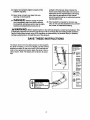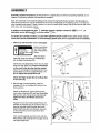
1
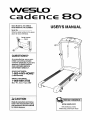
WESLO
c d nce
Sears Model No. 831.24602.0
Kmart Model No. WLTL29306.0
BO
USER'S MANUAL
Serial No.
Write the serial number in the space
above for future reference.
Serial Number
Decal
QUESTIONS?
As a manufacturer, we are committed to providing complete
customer satisfaction. If you have
questions, PLEASE CONTACT
OUR CUSTOMER SERVICE
DEPARTMENT DIRECTLY.
SEARS CUSTOMERS:
1-800-4-MY-HOME ®
(1-800-469-4663)
KMART CUSTOMERS:
1-866-699-3756
Mon.-Fri., 6 a.m.-6 p,m. MST
CAUTION
Read all precautions and Instructions in this manual before using
this equipment. Save this manual
for future reference,
www.weslo.com
new products, prizes,
fitness tips, and much more!
WESLO
°
80
TABLE OF CONTENTS
IMPORTANT PRECAUTIONS .................................................................
BEFORE YOU BEGIN .......................................................................
ASSEMBLY ...............................................................................
OPERATION AND ADJUSTMENT ............................................................
HOW TO FOLD AND MOVE THE TREADMILL ..................................................
MAINTENANCE AND TROUBLESHOOTING ....................................................
CONDITIONING GUIDELINES ...............................................................
ORDERING REPLACEMENT PARTS ..................................................
3
5
6
10
13
15
17
Back Cover
Note: A PART IDENTIFICATION CHART, an EXPLODED DRAWING, and a PART LIST are attached in the
center of this manual.
WESLO is a registered trademark of ICON IP, Inc.
2
IMPORTANT
PRECAUTIONS
WARNING:
To reduce the risk of burns, fire, electdc shock, or injury to persons, read the
following important precautions and information before operating the treadmill.
1. It is the responsibility of the owner to ensure
that all users of this treadmill are adequately
informed of all warnings and precautions.
2.
Use the treadmill only as described.
3. Place the treadmill on a level surface, with at
least eight feet of clearance behind it and two
feet on each side. Do not place the treadmill
on any surface that blocks air openings. To
protect the floor or carpet from damage, place
a mat under the treadmill.
4. Keep the treadmill indoors, away from moisture and dual Do not put the treadmill In a
garage or covered patio, or near water.
5. Do not operate the treadmill where aerosol
products are used or where oxygen is being
administered.
6. Keep children under the age of 12 and pets
away from the treadmill at all times.
7. The treadmill should not be used by persons
weighing more than 250 pounds.
8. Never allow more than one person on the
treadmill at a time.
9, Wear appropdate exercise clothes when
using the treadmill. Do not wear loose clothes
that could become caught in the treadmill.
Athletic support clothes are recommended for
both men and women. Always wear athletic
shoes; never use the treadmill with bare feet,
wearing only stockings, or in sandals.
10. When connecting the power cord (see page 10),
plug the power cord into a surge suppreSsor
(not included) and plug the surge suppressor
into a grounded circuit capable of carrying 15
or more ampe. No other appliance should be on
the same circuit. Do not use an extension cord.
11. Use only a single-outlet surge suppressor that
meets all of the specifications described on
page 10. To purchase a surge suppressor, see
your local WESLO dealer or call the toll-free
telephone number on the front cover of this
manual and order part number 146148, or see
your local electronics store ....
12. Failure to use a properly functioning surge
suppressor could result in damage to the control system of the treadmill. If the control system is damaged, the walking belt may change
speed, accelerate, or stop unexpectedly,
which may result in a fall and serious injury.
13. Keep the power cord and the surge suppressor away from heated surfaces.
14. Never move the walking belt while the power
Is turned off. Do not operate the treadmill if
the power cord or plug is damaged, or if the
treadmill is not working properly. (See MAINTENANCE AND TROUBLESHOOTING on page
15 if the treadmill is not working properly.)
15. Read, understand, and test the emergency
stop procedure before using the treadmill (see
HOW TO TURN ON THE POWER on page 11).
16. Never start the treadmill while you are standing on the walking belt. Always hold the
handrails while using the treadmill.
17. The treadmill is capable of high speeds.
Adjust the speed In small increments to avoid
sudden jumps in speed.
18. Never leave the treadmill unattended while it is
running. Always remove the key and unplug
the power cord when the treadmill is not in use.
19. Do not attempt to raise, lower, or move the
treadmill until it is propedy assembled. (See
ASSEMBLY on page 6 and HOW TO FOLD
AND MOVE THE TREADMILL on page 13.)
You must be able to safely lift 45 pounds (20
kg) to raise, lower, or move the treadmill.
20. When folding or moving the treadmill, make
sure that the storage latch is fully closed.
21. Do not change the incline of the treadmill by
placing objects under the treadmill.
22.Inspectandproperlytightenallpartsofthe
treadmillregularly,
scribedinthis manual.Neverremovethe
motorhoodunlessinstructedto do so byan
authorizedservicerepresentative.
Servicing
otherthantheproceduresin this manual
shouldbeperformedby anauthorizedservice
representative
only.
23.Neverdropor insertanyobjectintoany
openingonthetreadmill,
24DANG ER: Always
unplug
thepower
cord immediately after use, before cleaning
the treadmill, and before performing the maintenance and adjustment procedures de-
WARNING:
25. This treadmill is intended for In-home use
only. Do not use th s treadm I in any commerclsl, rental, or institutional setting.
Before beginning this or any exercise program, consult your physician. This
is especially important for persons over the age of 35 or persons with pre-existing health problems.
Read all Instructions before using. ICON assumes no responsibility for persona Injury or property
damage sustained by or through the use of this product.
SAVE THESE INSTRUCTIONS
The decals shown here has been placed on the treadmill.
If a decal is missing, or if it is not legible, call the toll-free
telephone number on the front cover of this manual and
order a free replacement decal. Apply the decal in the location shown. Note: The decals are not shown at actual
size.
Protect y0_rsell and
o_Ps lrom nskofserious
injury R_adthe user's
manualar_ :
so_ raSt*h_
s'_i_J or ste_p_g
_dfnlL
_r_Ji roer_nts_
.H0_ ha_aib _
OOeta_l_ tread_L
.S_ _ youleel_Jnt
d_z_,or shut 0_
*FUI_
_
i
4
.K_
d0ra_
is rr_d
_
cl_lhi_ ¸
BEFORE YOU BEGIN
Thank you for selecting the WESLO _ CADENCE 80
treadmill. The CADENCE 80 treadmill combines advanced technology with innovative design to let you
enjoy an excellent form of cardiovascular exercise in
the convenience and privacy of your home. And when
you're not exercising, the unique CADENCE 80 treadmill can be folded up, requiring less than half the floor
space of other treadmills.
reading this manual, please see the front cover of this
manual. To help us assist you, note the product model
number and serial number before contacting us. The
model number is found on the front cover of this manual. The serial number is found on a decal attached to
the treadmill (see the front cover of this manual for the
location of the decal).
Before reading further, please review the drawing
below and familiarize yourself with the labeled parts.
For your benefit, read this manual carefully before
you use the treadmill. If you have questions after
Accessory Tray
Consote
Handrail
Key/Clip
Storage Latch
Hood
Walking Belt
Reset/Off
eaker
--
Foot Rail
Power Cord
.Wheel
Incline Pin/Leg
Rear Roller
Adjustment Bolts
5
ASSEMBLY
Assembly requires two persons. Set the treadmill in a cleared area and remove all packing materials; do not
dispose of the packing materials until assembly is completed.
Note: The underside of the treadmill walking belt is coated with high-performance lubricant. During shipping, a
small amount of lubricant may be transferred to the top of the walking belt or the shipping carton. This does not
affect treadmill performance. If there is lubricant on top of the walking belt, simply wipe off the lubricant with a soft
cloth and a mild, non-abrasive cleaner.
In addition to the included hex key-_s , assembly requires a phillips screwdriver (_,
adjustable wrench _,
an
and wire cutters _.
To identify the assembly hardware, see the PART IDENTIFICATION CHART in the center of this manual.
Some parts may be preassembled. To avoid damaging plastic parts, do not use power tools for assembly.
1. Make sure that the power cord is unplugged.
Have a second person hold the Base
(52) in the position
shown.
54
53
Attach six Base
Pads (63) (three are shown) to the Base (52)
with six Base Pad Screws (26).
26
14
Small
Holes
Identify the Left Upright (53), which has two small
holes near the upper end. Hold the Left Upright
so the small holes face the direction shown.
26
Attach the Left Upright to the Base (52) with two
Upright Bolts (2) and two Upright Washers (14),
Do not tighten the Upright Bolts yet.
Attach the Right Upright (54) to the Base (52)
in the same way.
2
2. With the help of a second person, raise the
Uprights (53, 54) so the Base (52) is flat on the
floor as shown.
Attach the Wheels (70) (one is shown) to the
outer sides of the Base (52) with two Wheel Bolts
(35) and two Nuts (16) as shown. Do not overtighten the Nuts; the Wheels should turn
freely.
Position the front end of the treadmill Frame (51)
between the Uprights (53, 54) as shown. Next, locate the long wire inside the lower end of the
Right Upright (see the inset drawing). Securely
tie the end of the wire to the end of the Wire
Harness (39).
51
Then, pull the opposite end of the wire until the
Wire Harness (39) extends from the upper end of
the Right Upright (54).
6
3. Have a second person lift and hold the front end
of the Frame (51). Hold a Frame Spacer (11) between the Right Upright (54) and the Frame.
Attach the Right Upright to the Frame with a
Frame Pivot Bolt (1), an Upright Washer (14), and
an Upright Star Washer (9). Do not tighten the
Frame Pivot Bolt yet.
Repeat this step on the left side of the treadmill.
51
4. Set the Console Assembly (91) face down on a
soft surface to avoid scratching the Console
Assembly. Set the Left Handrail (22) on the
Console as shown. Attach the Left Handrail with
two Console Screws (10).
4
22
Attach the Right Handrail (not shown) to the
other side of the Console Assembly (91) as described above.
91
5. Hold the Console Assembly (91) near the Right
Upright (54). Touch the Right Handrail (33) to
discharge any static.
5
Connector
91
Remove the wire from the end of the Wire
Harness (39). Insert the end of the Wire Harness
through the large holes in the bottom and side of
the Right Handrail (33) and through the two
looped plastic ties.
o
0%
33
Then, press the end of the Wire Harness (39) into
the connector on the back of the Console
Assembly (91) in the location shown. See the
inset drawing. The end of the Wire Harness
should slide easily into the connector and
snap into place, If it does not, turnthe end of the
Wire Harness and then insert it. IF THE CONNECTOR IS NOT INSERTED PROPERLY, THE
CONSOLE MAY BE DAMAGED WHEN THE
POWER IS TURNED ON.
39
Plastic
Ties
Connector
Insert the excess Wire Harness (39) downward
into the Right Upright (54). Tighten the two plastic
ties around the Wire Harness, and then cut off the
ends of the plastic ties.
7
6. Set the Left and Right Handrails (22, 33) and the
Console Assembly (91) on the Uprights (53, 54).
Tighten the four Handrail Bolts (8) with the four
Handrail Star Washers (5) into the Left and Right
Uprights (53, 54) and the Left and Right
Handrails (22, 33). Start all four Handrail Bolts
before tightening any of them.
91
7. Attach the Console Back (73) to the Console
Assembly (91) with four Console Back Screws
(4). Make sure that no wires are pinched.
7
73
91
ji
8
/
8. Carefully lower the Left and Right Handrails (22,
33) until they are touching the floor.
8
See the lower drawing. Position the Uprights (53,
54) so that the treadmill Frame (51) is centered
between the Uprights.
51
Firmly tighten the four Handrail Bolts (2) and the
two Frame Pivot Bolts (1) used in steps 1 and 3.
Be careful not to overtighten the Frame Pivot
Bolts,
Top View
o o
54
\
9. Attach the Latch Housing (48) to the Left Upright
(53) with two Latch Screws (7); start both Latch
Screws before tightening them. Make sure
that the large hole in the Latch Housing is on
the indicated side,
48
Remove the knob from the pin. Make sure that
the collar and the spring are on the pin. (Note: If
there are two collars, place one on each side of
the spring.) Insert the pin intothe Latch Housing
(48). Then, tighten the knob onto the pin.
10. Raise the Frame (51) to the storage position
(see HOW TO FOLD THE TREADMILL FOR
STORAGE on page 13). Attach an Incline Leg
(69) to the Frame (51) with an Incline Leg Bolt
(32), two Incline Leg Washers (43), and an
Incline Leg Nut (46) as shown.
Larg
10
Repeat this step on the other side of the
Frame (51),
Adjust the Incline Legs (69) to the desired level
(see HOW TO CHANGE THE INCLINE OF THE
TREADMILL on page 12).
11. Make sure that ell parts are properly tightened before you use the treadmill. Keep the included hex key
in a secure place. The hex key is used to adjust the walking belt (see page 16). To protect the floor or carpet,
place a mat under the treadmill.
OPERATION AND ADJUSTMENT
THE PRE-LUBRICATED WALKING BELT
tric shock. This product is equipped with a cord having
an equipment-grounding conductor and a grounding
plug. Plug the power cord into a surge suppressor,
and plug the surge suppressor into an appropriate
outlet that is properly installed and grounded in
accordance with all local codes and ordinances.
Important: The treadmill is not compatible with
GFCI-equipped outlets.
Your treadmillfeatures a walking belt coated with highperformance lubricant. IMPORTANT: Never apply silicone spray or other substances to the walking
belt or the walking platform. Such substances will
deteriorate the walking belt and cause excessive
wear.
HOW TO PLUG IN THE POWER CORD
DAN GE R: Improper connection
of the equipment-grounding conductor can
result in an increased risk of electric shock.
Check with a qualified electrician or serviceman if you are in doubt as to whether the
product is properly grounded. Do not modify
the plug provided with the product--it it will
not fit the outlet, have a proper outlet
Installed by a qualified electrician.
This product is for use on a nominal 120-volt circuit,
and has a groundingplug that looks like the plug illustrated in drawing 1 below. A temporary adapter that
lookslike the adapter illustrated in drawing 2 may be
used to connect the surge suppressor to a 2-pole
receptacle as shown in drawing 2 if a properly
grounded outlet is not available.
Your treadmill, like any other type of sophisticated
electronic equipment, can be seriously damaged by
sudden voltage changes in your home's power.
Voltage surges, spikes, and noise interference can
result from weather conditions or from other appliances being turned on or off. To decrease the possibility of your treadmill being damaged, always
use a surge suppressor with your treadmill (see
drawing 1 at the right). To purchase a surge suppressor, see your local WESLO dealer or call the
toll-free telephone number on the front cover of
this manual and order part number 146148, or see
your local electronics store.
Use only a single-outlet surge suppressor that Is
UL 1449 listed as a transient voltage surge suppressor (TVSS). The surge suppressor must have a
UL suppressed voltage rating of 400 volts or less
and a minimum surge dissipation of 450 joules.
The surge suppressor must be electrically rated for
120 volts AC and 15 amps. There must be a monitoring light on the surge suppressor to indicate
whether it is functioning properly. Failure to use a
properly functioning surge suppressor could result
in damage to the control system of the treadmill. If
the control system is damaged, the walking belt
may change speed, accelerate or stop unexpectedly, which may result in a fall and serious injury.
This product must be grounded. If it should malfunction or break down, grounding providesa path of least
resistance for electric current to reduce the risk of elec-
_l_Grounded
Outlet Box
_'-1
Surge Suppressor
._
_p_J_..
Grounding Pin
Grounding Pin
Grounded Outlet
Grounding Plug
i_Grounded
II ( _J
Outlet Box
Adapter
^
_'_-_1
Surge suppressor
Metal Screw
The temporary adapter should be used only until a
properly grounded outlet (drawing 1) can be installed
by a qualified electrician.
The green-colored rigid ear, lug, or the like extending
from the adapter must be connected to a permanent
ground such as a properly grounded outlet box cover.
Whenever the adapter is used it must be held in place
by a metal screw. Some 2-pole receptacle outlet box
covers are not grounded. Contact a qualified electrician to determine if the outlet box cover is
grounded before using an adapter.
10
CONSOLE DIAGRAM
A WARNING:To_u_ ,skofs_cus
injury,
standon foot railsbefore starting t_e3dmifl,readand
_derstand the user's r_anual,aft instructions,and the
warningsbefore use Keep childrenaway.
_
Speed
Increase
Button
Note: If there are sheets of clear plastic on the console, remove the plastic.
HOW TO TURN ON THE POWER
Plug in the power cord (see
page 10). Next, locate the
reset/off circuit breaker on
the treadmill frame near the
power cord. Make sure that
the circuit breaker is in the
reset position.
HOW TO OPERATE THE CONSOLE
B
Insert the key into the console.
See HOW TO TURN ON THE POWER at the left.
Position
Reset %
B
Press the Start button or the Speed increase
button to start the walking belt.
When either button is pressed, the walking belt will
begin to move at 1 mph. Hold the handrails and
begin walking.
Next, stand on the foot rails of the treadmill. Find the
clip attached to the key (see the drawing above), and
slide the clip securely onto the waistband of your
clothes. Then, insert the key into the console. After a
moment, the displays will light, Important: In an emergency situation, the key can be pulled from the
console, causing the walking belt to slow to a stop.
Test the clip by carefully taking a few steps backward; If the key is not pulled from the console, adjust the position of the clip.
As you exercise, change the speed of the walking
belt as desired by pressing the Speed Increase
and Decrease buttons. Each time a button is
pressed, the speed setting will change by 0.1
mph; if a button is held down, the speed setting
will change in increments of 0.5 mph. Note: After a
button is pressed, it may take a moment for the
walking belt to reach the selected speed setting.
Note: To prevent damage to the walking platform, always wear clean athletic shoes while using the treadmill. During the first few minutes that the treadmill is
used, inspectthe alignment of the walking belt, and
center the walking belt if necessary (see page 16).
To stop the walking belt, press the Stop button.
The time will begin to flash in one of the displays.
To restart the walking belt, press the Start button or
the Speed Increase button.
11
[]
Follow your progress with the displays.
The lower left
display--As you exercise, the lower left display can show the
elapsed time and the
distance that you have
walked or run.
When you are finished exercising, remove the
key from the console.
/
|
Step onto the foot mils,press the Stop button, and
remove the key. Keep the key in a secure place.
Then, switch the reset/off circuit breaker to the
"off" position and unplug the power cord.
L
HOW TO CHANGE THE INCLINE OF THE TREADMILL
The lower right display--The lower right
display can show the
approximate number of
calories that you have
burned and the speed
of the walking belt.
To vary the intensity of your exercise, you can change
the incline of the treadmill. There are three incline levels. Before changing the incline, remove the key
and unplug the power cord. Next, fold the treadmill
to the storage position (see page 13).
To change the incline, first remove the incline pin from
one of the incline legs. Adjust the incline leg to the desired position, and then fully reinsert the incline pin.
Adjust the other incline leg in the same way. CAUTION;
Before using the treadmill, make sure that both incline legs are at the same height and that both incline pins are fully inserted into the incline legs.
The upper
display--The
upper display
can show the
elapsed time,
the distance
that you have walked or run, the approximate number of calories that you have burned, or the speed
of the walking belt. Press the Display button repeatedly untilthe upper display shows the information that you are most interested in viewing. Note:
While informationis shown in the upper display,
the same information will not be shown in the
lower left or lower right display.
Incline
Pin
Pin_
To reset the displays, press the Stop button, remove the key, and then reinsertthe key.
Note: The console can
display speed and disJ_"
tance in either miles or
I-kilometers. To see
which unit of measurement is selected, first
remove the key intothe console. Next, hold down
the Stop button, insert the key, wait until you hear
a tone, and then release the Stop button. An "E"
for English miles or an "M" for metric kilometers will
appear in the upper display. Press the Speed
Increase button to change the unit of measurement, if desired. When the desired unit of measurement is selected, remove the key and then
reinsert it into the console.
After you have adjusted the incline legs, lower the
treadmill (see page 14).
12
HOW TO FOLD AND MOVE THE TREADMILL
HOW TO FOLD THE TREADMILL FOR STORAGE
Unplug the power cord. CAUTION: You must be able to
safely lift 45 Ibs. (20 kg) to raise, lower, or move the
treadmill.
1. Hold the metal frame firmly in the location shown by
the arrow at the right. CAUTION: To decrease the possibility of injury, do not lift the frame by the plastic
foot rails. Make sure to bend your legs and keep your
back straight. As you raise the frame, make sure to lift
with your legs rather than your back. Raise the frame
about halfway to the vertical position.
Frame
t
2. Move your right hand to the position shown and hold the
treadmill firmly. Using your left hand, pull the latch knob
to the left and hold it. Raise the frame until the catch is
past the latch pin. Then, slowly release the latch knob;
make sure that the catch is resting against the latch
pin.
To protect the floor or carpet from damage, place a
mat under the treadmill. Keep the treadmill out of direct sunlight, Do not leave the treadmill in the storage position in temperatures above 85°F (30°C).
HOW TO MOVE THE TREADMILL
Before moving the treadmill, convert the treadmill to the storage position as described above. Make sure that the catch
is resting against the latch pin.
1. Hold the handrails and place one foot against one of the
wheels. Do not pull back on the frame.
2. Tilt the treadmill backward until it mils freely on the wheels,
and carefully move the treadmill to the desired location.
Never move the treadmill without tipping it backward,
To reduce the risk of injury, use extreme caution
while moving the treadmill. Do not attempt to move
the treadmill over an uneven surface.
3. Place one foot against one of the wheels, and carefully
lower the treadmill until it is in the storage position.
13
Handrail
/
HOW TO LOWER THE TREADMILL FOR USE
1. Hold the upper end of the treadmill with your right hand as
shown. Using your left hand, pull the latch knob to the left
and hold it. Next, lower the frame until it is past the latch
pin. Then, release the latch knob.
Latch
2. Hold the frame firmly with both hands, and lower it to the
floor. To decrease the possibility of injury, bend your
legs and keep your back straight.
/
Frame
14
MAINTENANCE AND TROUBLESHOOTING
Most treadmill problems can be solved by following the steps below. Find the symptom that applies, and
follow the steps listed. If further assistance is needed, please see the front cover of this manual.
PROBLEM: The power does not turn on
SOLUTION: a. Make sure that the power cord is plugged into a surge suppressor, and that the surge suppressor
is plugged into a properly grounded outlet (see page 10). Use onlya single-outletsurge suppressor that meets all of the specificationsdescribed on page 10. Important:The treadmill is not compatible with GFCI-equipped outlets.
b. After the power cord has been plugged in, make sure that the key is fully inserted into the console.
c. Check the reset/off circuit breaker located on the
treadmill frame near the power cord. If the switch
protrudes as shown, the circuit breaker has tripped.
To reset the circuit breaker, wait for five minutes,
and then press the switch back in.
Tripped
PROBLEM: The power turns off during use
SOLUTION: a. Check the reset/off circuitbreaker (see the drawing above). If the circuit breaker has tripped, wait
for five minutes and then press the switch back in.
b. Make sure that the power cord is plugged in.
c. Remove the key from the console. Reinsert the key fully into the console.
d. If the treadmill still will not run, please see the frontcover of this manual.
PROBLEM: The displays of the console do not function properly
SOLUTION: a. Remove the key from the console and UNPLUG THE
POWER CORD. Remove the five indicated Screws
a
65
20
(20). Then, carefully remove the Hood (65).
Locate the Reed Switch (89) and the Magnet (62) on
the left side of the Pulley (71). Turn the Pulley until the
Magnet is aligned with the Reed Switch. Make sure
that the gap between the Magnet and the Reed
Switch is about 1/8". If necessary, loosen the Screw
(21), move the Reed Switch slightly,and then
retightenthe Screw. Reattach the Hood (not shown),
and run the treadmill for a few minutes to check for a
correct speed reading.
15
TopveS
PROBLEM:
The walking belt slows when walked on
SOLUTION: a. Use only a single-outlet surge suppressor that meets all of the specifications described on page 10.
b*
If the walking belt is overfightened, treadmill performance may decrease and the walking belt may become damaged. Remove the key and UNPLUG THE
POWER CORD. Using the hex key, turn both rear
roller bolts counterclockwise, 1/4 of a turn. When the
walking belt is properly tightened, you should be able
to lift each edge of the walking belt 2 to 3 inches off
the walking platform. Be careful to keep the walking
belt centered. Then, plug in the power cord, insert the
key, and run the treadmill for a few minutes. Repeat
until the walking belt is properly tightened.
Bolts
c. If the walking belt still slows when walked on, see the front cover of this manual.
PROBLEM: The walking belt is oft-center or slips when walked on
SOLUTION: a. If the walking belt has shifted to the left, first remove the key and UNPLUG THE POWER CORD.
Using the hex key, turn the left rear roller boltclockwise 1/2 of a turn. Be careful not to overtighten the
walking belt. If the walking belt has shifted to the
right, turn the left rear rollerboltcounterclockwise1/2
of a turn. Then, plug in the power cord, insert the key,
and run the treadmillfor a few minutes. Repeat until
the walking belt is centered.
SOLUTION: a. If the walking belt slips when walked on, first remove
the key and UNPLUG THE POWER CORD. Using the
hex key, turn both rear roller bolts clockwise, 1/4 of a
turn. When the walking belt is correctly tightened, you
should be able to lift each edge of the walking belt 2 to
3 inches off the walking platform. Be careful to keep
the walking belt centered. Then, plug in the power
cord, insert the key, and carefully walk on the treadmill
for a few minutes. Repeat until the walking belt is
properly tightened.
16
CONDITIONING GUIDELINES
Aerobic Exercise
The following guidelines will help you to plan your exercise program. Remember that proper nutrition and
adequate rest are essential for successful results.
If your goal is to strengthen your cardiovascular system, your exercise must be "aerobic." Aerobic exercise
is activity that requires large amounts of oxygen for
prolonged periods of time. This increases the demand
on the heart to pump blood to the muscles, and on the
lungs to oxygenate the blood. For effective aerobic exercise, adjust the intensity of your exercise until your
heart rate is near the highest number in your training
zone.
WARNING: Before
beginning this
or any exercise program, consult your physician. This is especially important for individuals over the age of 35 or individualswithpre-existing health problems.
EXERCISEINTENSITY
HOW TO MEASURE YOUR HEART RATE
Whether your goal is to burn fat or to strengthen your
cardiovascular system, the key to achieving the desired results is to exercise with the proper intensity.
The proper intensity level can be found by using your
heart rate as a guide. The chart below shows
recommended heart rates for fat burning and aerobic exercise.
To measure your heart
rate, stop exercising
and place two fingers on
your wrist as shown.
Take a six-second
heartbeat count, and
multiply the result by ten
to find your heart rate.
(A six-second count is used because your heart rate
drops quickly when you stop exercising.)
165
155
145
140
130
125
115
145
138
130
125
118
110
103
125
120
115
110
105
95
90
20
30
40
50
60
70
80
WORKOUT GUIDELINES
Each workout should include the following three important parts:
A warm-up, consisting of five to ten minutes of
stretching and light exercise. This will increase your
body temperature, heart rate, and circulation in preparation for exercise.
To find the proper heart rate for you, first find your age
near the bottom of the chart (ages are rounded off to
the nearest ten years). Next, find the three numbers
above your age. The three numbers are your "training
zone." The lower two numbers are recommended
heart rates for fat burning; the highest number is the
recommended heart rate for aerobic exercise.
Training zone exercise, including 20 to 30 minutesof
exercise with your heart rate in your trainingzone.
A cool-down, consisting of five to ten minutes of
stretching. Stretching after exercise is effective for increasing flexibility and helps to offsetproblems caused
when you stop exercisingsuddenly.
Burning Fat
To burn fat effectively, you must exercise at the proper
intensity level for a sustained period of time. During the
first few minutes of exercise, your body uses easily accessible cafbohydratecalories for energy. Only after
the first few minutes does your body begin to use
stored/a/calories for energy. If your goal is to burn fat,
adjust the intensity of your exercise until your heart
rate is between the lower two numbers in your training
zone as you exercise.
EXERCISE FREQUENCY
To maintain or improve your condition, plan three
workouts each week, with at least one day of rest after
each workout. After a few months of regular exercise,
you may complete up to five workouts each week, if
desired. Remember, the key to success is to make exercise a regular and enjoyable part of your everyday
life.
17
SUGGESTED STRETCHES
The correct form for several basic stretches is shown at the right. Move slowlyas you stretch--never bounce.
1. Toe Touch Stretch
Stand with your knees bent slightly and slowly bend forward from
your hips. Allow your back and shoulders to relax as you reach
down toward your toes as far as possible. Hold for 15 counts, then
relax. Repeat 3 times. Stretches: Hamstrings, back of knees and
back.
2. Hamstring
Stretch
Sit with one leg extended. Bring the sole of the opposite foot toward
you and rest it against the inner thigh of your extended leg. Reach
toward your toes as far as possible. Hold for 15 counts, then relax.
Repeat 3 times for each leg. Stretches: Hamstrings, lower back and
groin.
3. Calf/Achilles Stretch
With one leg in front of the other, reach forward and place your
hands against a wall Keep your back leg straight and your back foot
flat on the floor. Bend your front leg, lean forward and move your
hips toward the wall. Hold for 15 counts, then relax. Repeat 3 times
for each leg. To cause further stretching of the achilles tendons,
bend your back leg as well. Stretches: Calves, achilles tendons and
ankles.
4. Quadriceps Stretch
With one hand against a wall for balance, reach back and grasp one
foot with your other hand. Bring your heel as close to your buttocks
as possible. Hold for 15 counts, then relax. Repeat 3 times for each
leg. Stretches: Quadriceps and hip muscles.
5. Inner Thigh Stretch
Sit with the soles of your feet together and your knees outward. Pull
your feet toward your groin area as far as possible. Hold for 15
counts, then relax. Repeat 3 times. Stretches: Quadriceps and hip
muscles.
18
2
NOTES
19
PART LIST
Key
No.
Qty.
1
2
3
4
5
6
7
8
9
10
11
12
13
14
15
16
17
18
19
2
4
1
4
4
1
2
4
2
4
2
4
2
6
1
2
1
1
4
20
21
22
23
24
25
26
27
28
29
30
31
32
33
34
35
36
5
18
1
1
1
10
6
2
4
2
2
1
2
1
2
2
2
SEARS MODEL
Description
Frame Pivot Bolt
Upright Bolt
Tie Holder Screw
Console Back Screw
Handrail Star Washer
Warning Decal
Latch Screw
Handrail Bolt
Upright Star Washer
Console Screw
Frame Spacer
Cage Nut
incline Pin
Upright Washer
Key/Clip
Nut
6 mm Hex Key
4 mm Hex Key
Roller Bracket Screw/
Front Platform Screw
Hood Screw
Screw
Left Handrail
Ground Screw
Latch Pin Assembly
Foot Rail Screw
Base Pad Screw
Walking Platform Bolt
Belt Guide Screw
Rear Roller Adj. Bolt
Motor Bolt
Motor Pivot Bolt
Incline Leg Bolt
Right Handrail
Motor Tension Bolt
Wheel Bolt
Rear Roller
Star Washer
NO. 831.24602.0;
Key
No.
Qty.
37
1
38
39
40
41
42
2
1
1
11
4
43
44
45
46
47
48
49
50
51
52
53
54
55
56
57
58
59
60
4
2
2
2
5
1
1
2
1
1
1
1
1
1
1
2
1
1
61
1
62
63
64
65
66
67
68
69
70
1
6
1
1
1
1
1
2
2
KMART
MODEL
Description
Reset]Off
Circuit Breaker
Motor Star Washer
Wire Harness
Ground Star Washer
Screw
Electronics Star
Washer
Incline Leg Washer
Motor Tension Nut
Frame Pivot Nut
Incline Leg Nut
Hood Clip
Latch Housing
Upright Grommet
isolator Fastener
Frame
Base
Left Upright
Right Upright
Rear Roller
Motor Belt
Electronics Bracket
Latch Catch Screw
Motor Bracket
Left Rear
Roller Bracket
Right Rear
Roller Bracket
Magnet
Base Pad
Latch Catch
Hood
Belly Pan
Left Foot Rail
Right Foot Rail
Incline Leg
Wheel
NO. WLTL29306.O
Key
No.
Qty.
71
72
73
74
75
76
77
78
79
80
81
82
83
84
85
1
1
1
2
2
1
4
2
1
4
4
2
1
1
1
86
87
88
89
90
91
92
93
94
#
#
#
#
#
#
#
#
1
1
1
1
1
1
1
2
1
1
1
1
1
1
1
1
1
R0706A
Description
Front Roller/Pulley
Ground Wire
Console Back
Frame Endcap
Base Endcap
Walking Belt
Handrail Endcap
Platform Cushion
Drive Motor
Wire Tie
8" Tie
Tie Holder
Reed Switch Clip
Belly Pan Grommet
Power Cord
Strain Relief
Walking Platform
Controller
Choke
Reed Switch
Power Cord
Console Assembly
Ground Wire
Belt Guide
M5 Hex Key
6" Red Wire, M/F
4" Black Wire, M/F
4" Blue Wire, M/F
8" Blue Wire, 2F
10" Blue Wire, 2F
6" White Wire, 2F
10" White Wire, 2F
User's Manual
# These parts are not illustrated.
Specifications are subject to
change without notice.
EXPLODED DRAWING
SEARS
MODELNO.
R0706A
KMARTMODELNO.
WLTL29306.0
831.24602.0;
91
15
25=4
89
83 --_
92
I0
--40
=
33
77
31
41
77
\
41
21
8O
14
35
1
%
2O
13
69_
26
94
17
16
PART IDENTIFICATION
CHART
Remove this chart and use it to identify small parts during assembly, Save this chart and the EXPLODED
DRAWING/PART LIST for future reference.
ConsoLe
Back
Screw (4)-4
Console
Screw
(10)-4
Base Pad
Screw (26)--6
Latch Screw (7)-2
Handrail Bolt (8)-4
Incline Leg Bolt (32)-2
Upright Washer
(14)-6
Incline Leg
Washer (43)-4
©
Incline Leg Nut
(46)-2
Handrail Star
Washer (5)-4
Upright Bolt (2)-4
Upright Star
Washer (9)-2
Wheel Bolt (35)-2
Nut (16)-2
Frame Pivot Bolt (1)-2
D
D
ORDERING
REPLACEMENT
PARTS
To order replacement parts, please see the front cover of this manual. To help us assist you, be prepared to provide the following information when calling:
• the MODEL NUMBER of the product (Sears Model No. 831.24602.0; Kmart Model No. WLTL29306.0)
• the NAME of the product (WESLO CADENCE 80 treadmill)
• the SERIAL NUMBER of the product (see the front cover of this manual)
• the KEY NUMBER and DESCRIPTION of the desired part(s) (see the PART LIST and the EXPLODED
DRAWING in the center of this manual)
LIMITED WARRANTY
1
ICON Health & Fitness, Inc. (ICON) warrants this product to be free from defects in workmanship and
material, under normal use and service conditions,for a period of ninety (90) days from the date of purchase.
This warranty extends only to the original purchaser. ICON's obligation under this warranty is limited to
replacing or repairing, at ICON's option, the product through one of its authorized service centers. All repairs for which warranty claims are made must be preauthorized by ICON. This warranty does not extend to any product or damage to a product caused by or attributable to freight damage, abuse, misuse,
improper or abnormal usage or repairs not provided by an ICON authorized service center; products
used for commercial or rental purposes; or products used as store display models. No other warranty beyond that specifically set forth above is authorized by ICON.
ICON is not responsible or liable for indirect, special or consequential damages arising out of or in connection with the use or performance of the product or damages with respect to any economic loss, loss
of property, loss of revenues or profits, loss of enjoyment or use, costs of removal or installation or other
consequential damages of whatsoever nature. Some states do not allow the exclusion or limitation of incidental or consequential damages. Accordingly, the above limitation may not apply to you.
The warranty extended hereunder is in lieu of any and all other warranties and any implied warranties of
merchantability or fitness for a particular purpose is limited in its scope and duration to the terms set
forth herein. Some states do not allow limitations on how long an implied warranty lasts. Accordingly, the
above limitation may not apply to you.
This warranty gives you specific legal rights. You may also have other rights which vary from state to
state.
ICON HEALTH & FITNESS, INC., 1500 S. 1000 W., LOGAN, UT 84321-9813
Part No. 240403 R0706A
Printed in China © 2006 ICON IP, Inc.