1
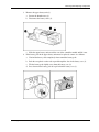
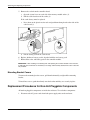
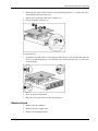
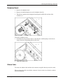
HP StorageWorks Modular Smart Array 20
Maintenance and Service Guide
July 2004 (First Edition)
Part Number 365511-001
© Copyright 2004 Hewlett-Packard Development Company, L.P.
The information contained herein is subject to change without notice. The only warranties for HP products and
services are set forth in the express warranty statements accompanying such products and services. Nothing herein
should be construed as constituting an additional warranty. HP shall not be liable for technical or editorial errors
or omissions contained herein.
HP StorageWorks Modular Smart Array 20 Maintenance and Service Guide
July 2004 (First Edition)
Part Number 365511-001
Contents
About This Guide
Audience Assumptions..................................................................................................................................v
Technician Notes...........................................................................................................................................v
Where to Go for Additional Help.................................................................................................................vi
Telephone Numbers ...............................................................................................................................vi
Chapter 1
Illustrated Parts Catalog
Chapter 2
Identifying Enclosure and Component Features
Buttons and LEDs on Enclosure Rear ....................................................................................................... 2-1
Disk Drives and Drive Blanks................................................................................................................... 2-2
Controller Module ..................................................................................................................................... 2-4
Fan Assembly ............................................................................................................................................ 2-5
Power Supply Unit .................................................................................................................................... 2-6
Chapter 3
Removing and Replacing Components
Preventing Electrostatic Damage .............................................................................................................. 3-1
Grounding Methods ............................................................................................................................ 3-1
Replacement Procedures for Hot-Pluggable Components ........................................................................ 3-2
Disk Drive or Drive Blank.................................................................................................................. 3-2
Fan Assembly ..................................................................................................................................... 3-3
Power Supply Unit.............................................................................................................................. 3-3
Controller Module............................................................................................................................... 3-4
Battery Packs and Cache (in the Controller Module) ......................................................................... 3-4
Mounting Bracket Covers ................................................................................................................... 3-6
Replacement Procedures for Non-Hot-Pluggable Components ................................................................ 3-6
Midplane Board .................................................................................................................................. 3-7
Backplane Board................................................................................................................................. 3-9
Ribbon Cable ...................................................................................................................................... 3-9
UID Circuit Board ............................................................................................................................ 3-10
VRM Power Supply.......................................................................................................................... 3-10
HP StorageWorks Modular Smart Array 20 Maintenance and Service Guide
iii
Contents
Chapter 4
Specifications
Power Specifications..................................................................................................................................4-1
Environmental Specifications ....................................................................................................................4-1
Physical Specifications ..............................................................................................................................4-2
iv
HP StorageWorks Modular Smart Array 20 Maintenance and Service Guide
About This Guide
This maintenance and service guide can be used for reference when servicing the
HP StorageWorks Modular Smart Array 20 enclosure.
WARNING: To reduce the risk of personal injury from electric shock and hazardous
energy levels, only authorized service technicians should attempt to repair this
equipment. Improper repairs can create conditions that are hazardous.
Audience Assumptions
This guide is for service technicians. HP assumes you are qualified in the servicing of
computer equipment and trained in recognizing hazard in products with hazardous energy
levels and are familiar with weight and stability precautions for rack installations.
Technician Notes
WARNING: Only authorized technicians trained by HP should attempt to repair this
equipment. All troubleshooting and repair procedures are detailed to allow only
subassembly/module-level repair. Because of the complexity of the individual boards
and subassemblies, no one should attempt to make repairs at the component level or
to make modifications to any printed wiring board. Improper repairs can create a safety
hazard.
WARNING: To reduce the risk of personal injury from electric shock and hazardous
energy levels, do not exceed the level of repairs specified in these procedures.
Because of the complexity of the individual boards and subassemblies, do not attempt
to make repairs at the component level or to make modifications to any printed wiring
board. Improper repairs can create conditions that are hazardous.
WARNING: To reduce the risk of electric shock or damage to the equipment:
•
Disconnect power from the system by unplugging all power cords from the power
supplies.
•
Do not disable the power cord grounding plug. The grounding plug is an important
safety feature.
•
Plug the power cord into a grounded (earthed) electrical outlet that is easily
accessible at all times.
HP StorageWorks Modular Smart Array 20 Maintenance and Service Guide
v
About This Guide
CAUTION: To properly ventilate the system, you must provide at least 7.6 cm (3.0 in.) of
clearance at the front and back of the enclosure.
CAUTION: The enclosure is designed to be electrically grounded (earthed). To ensure proper
operation, plug the AC power cord into a properly grounded AC outlet only.
NOTE: Any indications of component replacement or printed wiring board modifications may void any
warranty.
Where to Go for Additional Help
In addition to this guide, the following information sources are available:
•
User documentation
•
Service Quick Reference Guide
•
Service training guides
•
Service advisories and bulletins
•
QuickFind information services
•
Systems Insight Manager software
Telephone Numbers
For the name of the nearest HP authorized reseller:
•
In the United States, call 1-800-345-1518.
•
In Canada, call 1-800-263-5868.
For HP technical support:
vi
•
In the United States and Canada, call 1-800-633-3600.
•
Outside the United States and Canada, refer to http://www.hp.com.
HP StorageWorks Modular Smart Array 20 Maintenance and Service Guide
1
Illustrated Parts Catalog
The spare parts for the enclosure are illustrated on the following page.
HP StorageWorks Modular Smart Array 20 Maintenance and Service Guide
1-1
Illustrated Parts Catalog
Figure 1-1: Enclosure parts
1-2
HP StorageWorks Modular Smart Array 20 Maintenance and Service Guide
Illustrated Parts Catalog
Item
Description
Spare part number
1
Chassis
Not spared
2
Power supply unit
349800-001
3
Fan assembly
349798-001
4
Button and LED panel
Not spared
5
UID circuit board
361183-001
6
Controller module
Module shell (sheet metal) with controller board,
349797-001
Upper battery pack with cable, 349799-001
Lower battery pack, 307132-001
Cache board with battery, 309521-001
7
Enclosure lid
Not spared
8
VRM power supply
361741-001
9
Midplane
349795-001
10
Backplanes (two identical boards
per enclosure)
361740-001
11
Mounting bracket cover (bezel ear)
349801-001 (supplied in a kit with item 14)
12
Hard drive
Not spared as part of enclosure
13
Drive blank
Not spared as part of enclosure
14
Mounting bracket cover (bezel ear)
349801-001 (supplied in a kit with item 11)
15
Ribbon cable (connects item 5 to
item 9)
361739-001
Not
shown
Return kit
349803-001
HP StorageWorks Modular Smart Array 20 Maintenance and Service Guide
1-3
2
Identifying Enclosure and Component Features
Buttons and LEDs on Enclosure Rear
Figure 2-1: Enclosure buttons and LEDs
Item
Description
1
Arrow buttons (for future use)
2
Enclosure ID display— Indicates the ID number
assigned to the enclosure during drive configuration
3
Unit identification button— Causes the blue LED on all
drives in the enclosure to be illuminated
4
Enclosure monitor status LED— Illuminates green to
indicate that the enclosure monitor (Global Service
Indicator, or GSI) is functional
5
Enclosure fault LED— Illuminates amber when any
other LED in the enclosure is amber, if the GSI is
functional
6
Enclosure power button
HP StorageWorks Modular Smart Array 20 Maintenance and Service Guide
2-1
Identifying Enclosure and Component Features
Disk Drives and Drive Blanks
The drive bays on the front of the enclosure are numbered as follows:
1
4
7
10
2
5
8
11
3
6
9
12
The features of the drives and blanks are illustrated in Figure 2-2.
Figure 2-2: Drive (in carrier) and drive blank
Item
Description
1
Drive carrier
2
Release lever
3
Release button
4
Fault/ID bicolor LED (amber or blue)
5
Online LED (green)
6
Drive blank
7
Release latch
The blue ID LED illuminates when you press the unit identification button on the rear of the
enclosure. This LED also illuminates when the drive or an array containing the drive is
selected in a management application, such as the HP Array Configuration Utility (ACU).
The amber LED on a drive illuminates when the drive has failed or when a management
application predicts that it will fail in the near future.
For more information about the meaning of various drive LED illumination patterns, refer to
Table 2-1.
2-2
HP StorageWorks Modular Smart Array 20 Maintenance and Service Guide
Identifying Enclosure and Component Features
Table 2-1: Interpreting the Drive Status LEDs
Online LED
(green)
Fault/ID LED
(amber/blue)
Meaning
On, off, or
flashing
Alternating
between amber
and blue
The drive has failed, or a predictive failure alert* has been received for this
drive. It has also been selected by a management application.
On, off, or
flashing
Steadily blue
The drive is operating normally, and it has been selected by a management
application.
On
Amber, flashing
regularly (1 Hz)
A predictive failure alert* has been received for this drive. Replace the drive
as soon as possible.
On
Off
The drive is online, but it is not currently active.
Flashing
regularly (1 Hz)
Amber, flashing
regularly (1 Hz)
The drive is part of an array that is undergoing capacity expansion or stripe
migration, but a predictive failure alert* has been received for this drive. To
minimize the risk of data loss, do not replace the drive until the expansion or
migration is complete.
Flashing
regularly (1 Hz)
Off
The drive is rebuilding, or it is part of an array that is undergoing capacity
expansion or stripe migration.
Flashing
irregularly
Amber, flashing
regularly (1 Hz)
The drive is active, but a predictive failure alert* has been received for this
drive. Replace the drive as soon as possible.
Flashing
irregularly
Off
The drive is active, and it is operating normally.
Off
Steadily amber
A critical fault condition has been identified for this drive, and the controller
has placed it offline. Replace the drive as soon as possible.
Off
Amber, flashing
regularly (1 Hz)
A predictive failure alert* has been received for this drive. Replace the drive
as soon as possible.
Off
Off
The drive is either offline, a spare, or not configured as part of an array.
*Predictive failure alerts can occur only when the MSA20 is connected to a Smart Array controller. For information
about interpreting the drive fault LED when the MSA20 is connected to an MSA1500 cs, refer to the release notes at
http://www.hp.com/go/msa1500cs.
HP StorageWorks Modular Smart Array 20 Maintenance and Service Guide
2-3
Identifying Enclosure and Component Features
Controller Module
Figure 2-3: Controller module
Item
2-4
Description
1
Upper cache battery
2
Finger hook
3
Bicolor status LED (green or amber)
4
VHDCI connector (for connecting to a sixth-generation
Smart Array controller or an MSA1500 cs enclosure)
5
Service port
6
Release lever
7
Controller cache (lower cache battery just visible)
HP StorageWorks Modular Smart Array 20 Maintenance and Service Guide
Identifying Enclosure and Component Features
Fan Assembly
Figure 2-4: Fan assembly
Item
Description
1
Bicolor status LED (green or amber)
2
Release lever
HP StorageWorks Modular Smart Array 20 Maintenance and Service Guide
2-5
Identifying Enclosure and Component Features
Power Supply Unit
Figure 2-5: Power supply unit
Item
Description
1
Handle
2
AC power inlet
3
Release lever
4
Bicolor status LED (green or amber)
WARNING: Do not use the handles on the power supply units to lift or hold the
enclosure. These handles are designed only for holding the power supply units or
removing them from the enclosure, not for supporting the weight of the enclosure.
2-6
HP StorageWorks Modular Smart Array 20 Maintenance and Service Guide
3
Removing and Replacing Components
Some enclosure components are hot-pluggable, while others should be replaced only after
you have disconnected the enclosure from the AC power source.
Table 3-1: Classification of Components
Hot-pluggable
Not hot-pluggable
Mounting bracket covers (bezel ears)
Midplane board
Hard drive or drive blank
Backplane board
Power supply unit
UID circuit board
Fan assembly
VRM power supply
Controller module
Preventing Electrostatic Damage
A discharge of static electricity from a finger or other conductor might damage system boards
or other static-sensitive devices. This type of damage can reduce the life expectancy of the
device.
To prevent electrostatic damage when setting up the system or handling parts:
•
Avoid hand contact by transporting and storing products in static-safe containers.
•
Keep electrostatic-sensitive parts in their containers until they arrive at static-free
workstations.
•
Place parts on a grounded surface before removing them from their containers.
•
Avoid touching pins, leads, or circuitry.
•
Always be properly grounded when touching a static-sensitive component or assembly.
Grounding Methods
There are several methods for grounding. Use one or more of the following methods when
handling or installing electrostatic-sensitive parts:
HP StorageWorks Modular Smart Array 20 Maintenance and Service Guide
3-1
Removing and Replacing Components
•
Use a wrist strap connected by a ground cord to a grounded workstation or computer
chassis. Wrist straps are flexible straps with a minimum of 1 megohm ± 10 percent
resistance in the ground cords. To provide proper ground, wear the strap snug against the
skin.
•
Use heel straps, toe straps, or boot straps at standing workstations. Wear the straps on
both feet when standing on conductive floors or dissipating floor mats.
•
Use conductive field service tools.
•
Use a portable field service kit with a folding static-dissipating work mat.
Replacement Procedures for Hot-Pluggable Components
Removing a hot-pluggable component causes a significant change in the airflow within the
enclosure, and the enclosure could overheat if a replacement component is not installed
within a relatively short time.
•
Before removing a component from the enclosure, be sure that a replacement component
is immediately available.
•
If removing a drive, replace it with another drive or a drive blank to maintain the correct
airflow in the enclosure.
CAUTION: Be careful when replacing a drive. The drives in the enclosure are fragile.
The following general steps apply to all components. Detailed procedures for removing
individual components are given in the appropriate section of this chapter.
1. Remove the replacement component from its static-free container.
2. Check the label on the replacement component to be sure that it is of the correct type.
3. Remove the defective component from the enclosure.
4. Install the replacement component in the enclosure.
5. Observe the status LED of the replacement to confirm that the new component is
operating properly.
6. Place the defective component in the static-free container for shipment.
Disk Drive or Drive Blank
Removing a Drive Blank
Squeeze the release latch and hold it in while pulling the blank out of the enclosure.
Removing a Disk Drive
1. Press the release button.
3-2
HP StorageWorks Modular Smart Array 20 Maintenance and Service Guide
Removing and Replacing Components
2. Pull the drive out of the enclosure by about 3 cm (1 inch) so that it is disconnected from
the backplane connector.
CAUTION: A drive with a rapidly spinning disk can be difficult to hold securely. To decrease
the chance of dropping the drive, do not remove it completely from the enclosure until the disk
has stopped rotating. This usually takes a few seconds.
3. When the disk is no longer spinning, remove the drive from the enclosure.
Installing a Drive Blank
Insert the drive blank into the enclosure, and push it in until it is firmly seated in the
enclosure.
Installing a Replacement Drive
CAUTION: Take care when installing a drive. The drives in the enclosure are fragile.
1. Pull out the release lever on the drive as far as it can go.
2. Insert the replacement drive into the bay until it can go no further. About 1 cm (0.5 inch)
of the drive protrudes from the bay.
3. Push the release lever all the way in. This action installs the drive completely in the bay
and seats it firmly against the connector in the enclosure.
4. Observe the drive status LEDs to confirm that the replacement drive is functioning
correctly.
Fan Assembly
1. Lift the release lever and pull the fan assembly out of the enclosure.
2. Slide the replacement fan assembly into the enclosure until it is firmly seated in the
enclosure.
3. Confirm that the fan starts operating immediately and that the status LED is illuminated
green.
Power Supply Unit
1. Disconnect the AC power cord from the defective power supply unit.
2. Squeeze the handle and the release lever together while pulling the defective power
supply unit out of the enclosure.
3. Insert the replacement power supply unit into the empty bay until it is firmly seated in the
enclosure.
4. Connect the AC power cord.
5. Confirm that the status LED on the replacement unit is illuminated green.
HP StorageWorks Modular Smart Array 20 Maintenance and Service Guide
3-3
Removing and Replacing Components
Controller Module
1. Back up the data on the system.
2. Stop data transfers.
3. Disconnect the VHDCI cable.
4. Squeeze the release lever and the finger hook together while pulling the controller
module out of the enclosure.
5. Transfer the cache and batteries from the degraded controller module to the replacement
controller module.
6. Insert the replacement controller module into the enclosure until it is firmly seated in the
enclosure.
7. Connect the VHDCI cable to the connector on the new controller module.
CAUTION: To prevent damage to the cable connector, do not use excessive force when
tightening the thumbscrews on the connector.
8. Confirm that the status LED on the replacement module is illuminated green.
Battery Packs and Cache (in the Controller Module)
WARNING: There is a risk of explosion, fire, or personal injury if the battery pack is not
properly handled. To reduce this risk:
•
Do not try to recharge the batteries if they are disconnected from the controller.
•
Do not expose the battery pack to water, or to temperatures higher than 60°C.
•
Do not abuse, disassemble, crush, or puncture the battery pack.
•
Do not short the external contacts.
•
Replace the battery pack only with the designated HP spare.
Battery disposal should comply with local regulations. Alternatively, use established
parts return methods to return the battery pack to HP for disposal.
IMPORTANT: When replacing either battery, disconnect both batteries from the controller board as
described in these instructions. This ensures that the circuitry on the controller board is reset, and the
controller can then recognize the new battery.
1. Flush the cache.
2. Remove the controller module from the enclosure (for detailed instructions, refer to the
Controller Module section).
3-4
HP StorageWorks Modular Smart Array 20 Maintenance and Service Guide
Removing and Replacing Components
3. Remove the upper battery unit (1).
a. Loosen the thumbscrews (2).
b. Disconnect the battery cable (3).
c. Slide the upper battery unit toward the rear of the controller module and lift it out.
4. If the battery pack in the upper battery unit must be replaced, remove it as follows:
a. Unwind the battery cable completely from around the battery pack.
b. Push the two plastic retainer tabs up and through the slots in the battery case (1).
c. Tilt the battery pack slightly away from the battery case (2).
d. Press down on the battery pack to expel it from the battery case (3).
HP StorageWorks Modular Smart Array 20 Maintenance and Service Guide
3-5
Removing and Replacing Components
5. Remove the cache from the controller board:
a. Open the ejector levers on each side of the memory module socket (1).
b. Pull the cache board out of the socket (2).
If the cache battery must be replaced:
a. Press down on the plastic retainer tabs and push them through to the other side of the
cache board (3).
b. Lift the battery pack off the cache board.
6. Replace whichever battery pack is degraded with the new battery pack.
7. Reinstall the cache and battery packs in the controller module.
IMPORTANT: After installing a new battery pack and replacing the controller module in the enclosure,
it might take up to 45 minutes for the battery to recharge and the battery-backed write cache to become
fully enabled.
Mounting Bracket Covers
To remove the mounting bracket covers, pull them horizontally straight off the mounting
bracket.
To install new covers, push them firmly onto the bracket until they are securely in place.
Replacement Procedures for Non-Hot-Pluggable Components
All non-hot-pluggable components are inside the enclosure. To reach these components:
1. Disconnect the AC power cords from both power supply units on the enclosure.
3-6
HP StorageWorks Modular Smart Array 20 Maintenance and Service Guide
Removing and Replacing Components
2. Rotate the slot in the enclosure lid lever to the unlocked position (1), as indicated by the
open padlock embossed in the lever.
3. Pull the lever toward the front of the enclosure (2).
4. Lift the lid off the enclosure (3).
To replace the lid:
1. Position the lid on the chassis so that the peg on the chassis (1) fits into the hole under the
lid lever, and the flanged pegs (2) on the inner edge of the lid fit into slots (3) on the side
of the enclosure.
2. Press the lid lever fully down.
3. Rotate the slot in the lid lever to the locked position.
Midplane Board
1. Remove the fan assemblies.
2. Remove the power supply units.
3. Remove the controller module.
HP StorageWorks Modular Smart Array 20 Maintenance and Service Guide
3-7
Removing and Replacing Components
4. Disconnect the ribbon cable from the midplane board.
5. Loosen the captive thumbscrews (1).
6. Pull or push against the captive thumbscrews to slide the midplane board toward the rear
of the enclosure (2).
7. Tilt the board lengthwise and manipulate it to get it out of the chassis.
To replace the midplane board:
1. Manipulate the board so that it rests flat on the chassis floor, and the standoffs on the
chassis floor are visible through the plastic windows in the board.
2. Push firmly against the edge of the board (1) so that the standoffs are hidden under the
copper connectors in the plastic windows. The board is now grounded and the midplane
is electrically connected to the backplanes.
3. Tighten the captive thumbscrews (2).
4. Replace the fan assemblies, power supply units, and controller module.
3-8
HP StorageWorks Modular Smart Array 20 Maintenance and Service Guide
Removing and Replacing Components
Backplane Board
1. Remove the midplane board.
2. Remove the knurled thumbscrew on the backplane board (1).
3. Tilt the lower portion of the backplane board upward and lift the board out of the
enclosure (2).
To install a backplane board:
1. Position the board against the chassis so that the three rounded prongs on the chassis
engage with the corresponding holes in the board.
2. Tighten the thumbscrew.
Ribbon Cable
To remove the ribbon cable, hold the cable connector and pull it directly out of the socket.
When replacing the cable, note that the connector is keyed so that it can fit in the socket in
only one orientation.
HP StorageWorks Modular Smart Array 20 Maintenance and Service Guide
3-9
Removing and Replacing Components
UID Circuit Board
1. Disconnect the ribbon cable from the UID circuit board.
2. Remove the two screws (1).
3. Remove the UID LED and button panel (2).
NOTE: Take care that the plastic window does not fall out of the panel and get lost.
4. Tilt the edge of the board upward, and pull the board out of the chassis (3).
To install a UID circuit board, reverse this procedure.
VRM Power Supply
1. Pull out the latches on both sides of the socket (1).
2. Pull the VRM power supply straight out of the socket (2).
To install a VRM power supply, reverse this procedure. If the latches do not click into place,
press them in manually to secure the VRM power supply module in the socket.
3-10
HP StorageWorks Modular Smart Array 20 Maintenance and Service Guide
4
Specifications
Power Specifications
Table 4-1: AC Input Requirements
Nominal Value
Range
Frequency (±5%)
50 or 60 Hz
47 to 63 Hz
Voltage
110 or 240 V
90 to 254 V RMS
(autoranging)
Steady state maximum current
At 240 V: 1.8 A (one power supply) or
1.9 A (two power supplies)
—
At 120 V: 3.7 A (one power supply) or
3.9 A (two power supplies)
Standby current
0.21 A at 240 V, 60 Hz
—
0.15 A at 120 V, 60 Hz
Environmental Specifications
Table 4-2: Environmental Specifications
Operating
Shipping or Storage
10° to 35°C (5 0° to 95°F), with an aver age
change of less than 1°C p er hour and a step
change of less than 3°C p er hour
–40° to 66° C
Relative humidity
(noncondensing)
40% to 60%, with a step change of less than
10%
10% to 80%
Air quality
Fewer than 500,000 particles 0.5 micron or
larger per cubic foot (approximately 17,700 per
liter)
—
Heat dissipation
1175 BTU/hr (345 W)
—
Ambient temperature
HP StorageWorks Modular Smart Array 20 Maintenance and Service Guide
–40° to 15 0°F
4-1
Specifications
Physical Specifications
Table 4-3: Enclosure Specifications
Form
Unpacked
Dimensions
Weight
International (cm)
US (in)
59.7 x 48.8 x 8.8
23.5 x 19.2 x 3.5
14 kg (32 lb) empty
24 kg (53 lb) with components
In shipping carton
83.8 x 81.3 x 27.4
33.0 x 32.0 x 10.8
25 kg (55 lb) empty
34 kg (75 lb) with components
Table 4-4: Specifications of Components
Form
4-2
Dimensions
Weight
International (cm)
US (in)
Fan assembly
26.8 x 6.0 x 6.0
10.6 x 2.4 x 2.4
0.50 kg (1.10 lb)
Disk drive (in carrier)
18.5 x 11.0 x 2.6
7.3 x 4.3 x 1.0
0.75 kg (1.65 lb)
Controller module
32.6 x 7.9 x 7.1
12.8 x 3.1 x 2.8
1.4 kg (3.0 lb)
Power supply unit
32.0 x 6.4 x 7.7
12.6 x 2.5 x 3.0
1.80 kg (3.96 lb)
HP StorageWorks Modular Smart Array 20 Maintenance and Service Guide