1
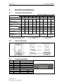
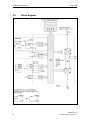
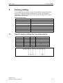
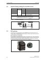
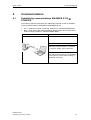
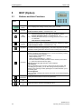
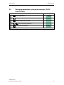
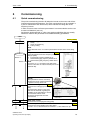
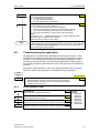
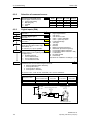
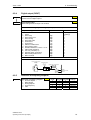
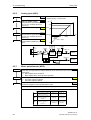
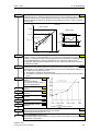
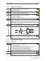
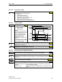
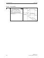
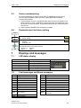
Operating Instructions (Compact) Issue 11/04 sinamics SINAMICS G110 Warnings, Cautions and Notes Issue 11/04 The Compact version of the Operating Instructions will cover the majority of typical applications. It is valid for inverters firmware versions 1.0 and 1.1. For full details please refer to the Operating Instructions and the Parameter List. Warnings, Cautions and Notes The following Warnings, Cautions and Notes are provided for your safety and as a means of preventing damage to the product or components in the machines connected. Specific Warnings, Cautions and Notes that apply to particular activities are listed at the beginning of the relevant chapters and are repeated or supplemented at critical points throughout these chapters. Please read the information carefully, since it is provided for your personal safety and will also help prolong the service life of your SINAMICS G110 Inverter and the equipment you connect to it. ! 2 WARNING ¾ This equipment contains dangerous voltages and controls potentially dangerous rotating mechanical parts. Non-compliance with Warnings or failure to follow the instructions contained in this manual can result in loss of life, severe personal injury or serious damage to property. ¾ Only suitable qualified personnel should work on this equipment, and only after becoming familiar with all safety notices, installation, operation and maintenance procedures contained in this manual. The successful and safe operation of this equipment is dependent upon its proper handling, installation, operation and maintenance. ¾ The DC link of all SINAMICS G110 modules remains at a hazardous voltage level for 5 minutes after all voltages have been disconnected. Therefore always wait for 5 minutes after disconnecting the inverter from the power supply before carrying out work on any modules. The drive unit discharges itself during this time. ¾ The mains input, DC and motor terminals carry dangerous voltages even if the inverter is inoperative, wait 5 minutes to allow the unit to discharge after switching off before carrying out any installation work. ¾ During the parameter download with the STARTER commissioning tool or from the BOP to the inverter, the digital output may produce a spurious signal. Prior to performing a download to the inverter appropriate counter-measures must be taken to ensure that any suspended load is secured, for example, by the use of external brakes or the load being lowered to ground level and secured. SINAMICS G110 Operating Instructions (Compact) Issue 11/04 Warnings, Cautions and Notes NOTES ¾ This equipment is capable of providing internal motor overload protection in accordance with UL508C section 42 (refer to P0610 and P0335). I2t monitoring is ON by default. Motor overload protection can also be provided using an external PTC via a digital input. ¾ This equipment is suitable for use in a circuit capable of delivering not more than 10,000 symmetrical amperes (rms), for a maximum voltage of 230 V when protected by an H or K type fuse, a circuit breaker or self-protected combination motor controller. ¾ Use Class 1 75 °C copper wire only with the cross-sections as specified in Section 2.1 ¾ The maximum permissible ambient temperature is, depending on the equipment, 40 °C or 50 °C (refer to Section 2.1). ¾ Before installing and commissioning, please read these safety instructions and warnings carefully and all the warning labels attached to the equipment. ¾ Make sure that the warning labels are kept in a legible condition and replace missing or damaged labels. SINAMICS G110 Operating Instructions (Compact) Operating Instructions (Compact) 3 Warnings, Cautions and Notes 4 Issue 11/04 SINAMICS G110 Operating Instructions (Compact) Issue 11/04 Contents Contents 1 1.1 1.2 Installation ............................................................................................................... 6 Clearance distances for mounting ............................................................................ 6 Mounting dimensions ................................................................................................ 6 2 2.1 2.2 2.3 2.4 Electrical Installation.............................................................................................. 7 Technical specifications............................................................................................ 7 Power terminals ........................................................................................................ 7 Control terminals....................................................................................................... 7 Block diagram ........................................................................................................... 8 3 3.1 3.2 3.3 Factory setting ........................................................................................................ 9 Specific factory settings for the analog version ........................................................ 9 Specific factory settings for the USS version.......................................................... 10 DIP switches ........................................................................................................... 10 4 Communications................................................................................................... 11 4.1 Establishing communications SINAMICS G110 STARTER .............................. 11 5 5.1 5.2 5.3 BOP (Option) ......................................................................................................... 12 Buttons and their Functions .................................................................................... 12 Changing parameters using as an example P0003 "Access level"........................ 13 Cloning parameters with the BOP .......................................................................... 14 6 6.1 6.2 6.2.1 6.2.2 6.2.3 6.2.4 6.2.5 6.2.6 6.2.7 6.2.8 6.2.9 6.2.10 6.2.11 6.2.12 6.2.13 6.2.14 6.3 6.4 Commissioning ..................................................................................................... 15 Quick commissioning .............................................................................................. 15 Commissioning the application ............................................................................... 17 Serial interface (USS) ............................................................................................. 17 Selection of command source ................................................................................ 18 Digital inputs (DIN).................................................................................................. 18 Digital output (DOUT) ............................................................................................. 19 Selection of frequency setpoint............................................................................... 19 Analog input (ADC) ................................................................................................. 20 Motor potentiometer (MOP) .................................................................................... 20 Fixed frequency (FF)............................................................................................... 21 JOG......................................................................................................................... 21 Ramp-function generator (HLG) ............................................................................. 22 Reference / limit frequencies .................................................................................. 22 Motor control ........................................................................................................... 22 Inverter/motor protection......................................................................................... 24 Inverter-specific functions ....................................................................................... 24 Series commissioning ............................................................................................. 27 Parameter reset to factory setting........................................................................... 27 7 7.1 7.2 Displays and messages ....................................................................................... 27 LED status display .................................................................................................. 27 Fault messages and Alarm messages.................................................................... 27 SINAMICS G110 Operating Instructions (Compact) 5 1 Installation Issue 11/04 1 Installation 1.1 Clearance distances for mounting 100 mm Fig. 1-1 1.2 Flat Plate variant only FSA FSB FSC 15 mm SIDE OF CABINET ENCLOSURE SIDE OF CABINET ENCLOSURE The inverters can be mounted adjacent to each other. If they are mounted on top of each other, however, a clearance of 100 mm has to be observed. 100 mm >0 mm 30 mm 15 mm Clearance distances for mounting Mounting dimensions Frame Size A Drilling Dimensions H W mm (Inch) mm (Inch) 140 (5.51) 79 (3.11) Tightening Torque Bolts Nm (lbf.in) 2xM4 2,5 (22.12) Fig. 1-2 6 B 135 (5.31) 127 (5.00) 4xM4 C 140 (5.51) 170 (6.70) 4xM5 4,0 (35.40) Mounting dimensions SINAMICS G110 Operating Instructions (Compact) Issue 11/04 2 Electrical Installation 2 Electrical Installation 2.1 Technical specifications 1 AC 200 - 240 V r 10 %, 47 - 63 Hz Order No. 6SL3211- 0AB 11-2xy0* 12-5xy0* 13xy0* 15xy0* 17xy0* 21-1xy0* 21-5xy0* 22-2xy0* 23-0xy0* 0KB 11-2xy0* 12-5xy0* 13xy0* 15xy0* 17xy0* Frame Size Inverter Output Rating kW hp Output Current (perm. ambient temp.) Input Current (230 V) Recommended Fuse Input Cable Output Cable Tightening Torque of power terminals 0,12 0,16 0,25 0,33 0,37 0,5 0.9 1.7 (50 °C) 2.3 (50 °C) 2.3 4.5 6.2 A (50 °C) A A 3NA 2 mm AWG mm2 AWG 0,75 1,1 1,0 1,5 3.9 3.2 6.0 (50 °C) (40 ºC) (50 °C) 7.7 10.0 10 10 16 3803 3803 3805 Power terminals Fig. 2-1 Power Terminals 2.3 Control terminals - 14.7 0.96 (8.50) x = A/B o with integrated filter x = U o without filter - C 1,5 2,0 2,2 3,0 3,0 4,0 7.8 (40 ºC) 11.0 (50 °C) 13.6 (40 ºC) 19.7 27.2 32.0 35 3814 4,0 - 10 11 - 8 2,5 - 10 12 - 8 50 3820 6,0 - 10 10 - 8 2,5 - 10 12 - 8 20 25 3807 3810 1,0 - 2,5 1,0 - 2,5 1,0 - 2,5 1,0 - 2,5 1,5 - 2,5 2,5 - 6,0 2,5 - 6,0 16 - 12 16 - 12 16 - 12 16 - 12 14 - 12 12 - 10 12 - 10 1,0 - 2,5 1,0 - 2,5 1,0 - 2,5 1,0 - 2,5 1,0 - 2,5 1,5 - 6,0 1,5 - 6,0 16 - 12 16 - 12 16 - 12 16 - 12 16 - 12 14 - 10 14 - 10 10 3803 2.2 8 9 10 0,55 0,75 10 Nm (lbf.in) Designation DOUTDOUT+ DIN0 DIN1 DIN2 Variant ADC - - B 3803 *o the last digit of the Order No. depends on hardware and software changes Term. 1 2 3 4 5 6 7 - A 1.50 (13.30) 2.25 (19.91) y = A o analog version y = B o USS version Function Digital output (-) Digital output (+) Digital input 0 Digital input 1 Digital input 2 Isolated output +24 V / 50 mA Output 0 V Analog USS Output +10 V RS485 P+ Analog input RS485 NOutput 0 V SINAMICS G110 Operating Instructions (Compact) 7 2 Electrical Installation 2.4 Block diagram Fig. 2-2 Inverter block diagram 8 Issue 11/04 SINAMICS G110 Operating Instructions (Compact) Issue 11/04 3 3 Factory setting Factory setting The SINAMICS G110 frequency inverter has already been programmed at the factory (motor parameters P0304, P0305, P0307, P0310), for standard V/f applications on Siemens 4-pole asynchronous motors 1LA that have the same power rating as the inverters Further factory setting 3.1 Command sources P0700 see Section 3.1/3.2 Setpoint source P1000 see Section 3.1/3.2 Motor cooling P0335 = 0 (self-cooled) Motor current limit P0640 = 150% Min. frequency P1080 = 0 Hz Max. frequency P1082 = 50 Hz Ramp-up time P1120 = 10 s Ramp-down time P1121 = 10 s Control mode V/f P1300 = 0 (V/f with linear characteristic) Specific factory settings for the analog version Digital input Terminals Parameter Function Command source 3, 4, 5 P0700 = 2 Digital input Setpoint source 9 P1000 = 2 Analog input Digital input 0 3 P0701 = 1 ON / OFF1 (I/O) Digital input 1 4 P0702 = 12 Reverse ( Digital input 2 5 P0703 = 9 Fault reset (Ack) Control method - P0727 = 0 Siemens standard control Fig. 3-1 ) Connections, analog version SINAMICS G110 Operating Instructions (Compact) 9 3 Factory setting 3.2 Issue 11/04 Specific factory settings for the USS version Inputs Terminals Parameter Function Command source P0700 = 5 Via the USS protocol Setpoint source P1000 = 5 Frequency input via the USS protocol USS address P2011 = 0 USS address = 0 USS baud rate P2010 = 6 USS baud rate = 9600 bps USS-PZD length P2012 = 2 Two 16-bit words are in the PZD section of the USS telegram. Fig. 3-2 8, 9 Connections, USS version Bus termination SIMATIC S7-200 G110 G110 G110 max. 31 SINAMICS Fig. 3-3 3.3 Example, USS bus DIP switches The default motor base frequency of the SINAMICS G110 inverter is 50 Hz. For motors, which are designed for a base frequency of 60 Hz, the inverters can be set to this frequency via a DIP switch. Bus termination on USS variant It is necessary to terminate the last inverter on the network bus. This is achieved by setting the Bus Termination DIP switches (DIP switches 2 and 3) on the front of the inverter to the ‘Bus Termination’ position (ON position). A common 0 V reference (terminal 10) is required between all devices on the USS bus. Fig. 3-4 10 Motor Base Frequency DIP Switch and Bus Termination SINAMICS G110 Operating Instructions (Compact) Issue 11/04 4 Communications 4 Communications 4.1 Establishing communications SINAMICS G110 STARTER The following optional components are additionally required in order to establish communications between STARTER and SINAMICS G110: ¾ PC <-> frequency inverter connecting kit (order no 6SL3255-0AA00-2AA0) ¾ BOP, as far as the USS standard settings already kept in the Sinamics G110 shall be changed (order no 6SL3255-0AA00-4BA0) PC <-> SINAMICS G110 connecting Kit SINAMICS G110 USS settings, refer to Section 6.2.1, Page 17. STARTER Menu, Options --> Set PG/PC interface --> Select "PC COM-Port (USS)" --> Properties --> Interface "COM1", select a baud rate NOTE The USS parameter settings in the SINAMICS G110 frequency inverter and the settings in STARTER must match! SINAMICS G110 Operating Instructions (Compact) 11 5 BOP (Option) Issue 11/04 5 BOP (Option) 5.1 Buttons and their Functions Panel/ Button Function Effects Indicates Status The LCD displays the settings currently used by the converter. Start converter Pressing the button starts the converter. This button is disabled by default. Activate the button: P0700 = 1 or P0719 = 10 ... 15 OFF1 Stop converter OFF2 Pressing the button causes the motor to come to a standstill at the selected ramp down rate. This button is disabled by default. Activate the button: P0700 = 1 or P0719 = 10 ... 15 Pressing the button twice (or once long) causes the motor to coast to a standstill. This function is always enabled. Change direction Press this button to change the direction of rotation of the motor. Reverse is indicated by a minus (-) sign or a flashing decimal point. Disabled by default. Activate the button: P0700 = 1 or P0719 = 10 ... 15. Jog motor In the " Power-on/Ready" state, when this key is pressed, the motor starts and rotates with the pre-set jog frequency. The motor stops when the button is released. Pressing this button when the motor is running has no effect. Functions This button can be used to view additional information. It works by pressing and holding the button. It shows the following, starting from any parameter during operation: 1. DC link voltage (indicated by d – units V) 2. output frequency (Hz) 3. output voltage (indicated by o – units V). 4. The value selected in P0005 (If P0005 is set to show any of the above (1 - 3) then this will not be shown again). Additional presses will toggle around the above displays. Jump Function From any parameter (rxxxx or Pxxxx) a short press of the Fn button will immediately jump to r0000, you can then change another parameter, if required. Upon returning to r0000, pressing the Fn button will return you to your starting point. Acknowledgement If alarm and fault messages are present, then these can be acknowledged by pressing key Fn. Access Pressing this button allows access to the parameters. parameters 12 Increase value Pressing this button increases the displayed value. Decrease value Pressing this button decreases the displayed value. SINAMICS G110 Operating Instructions (Compact) Issue 11/04 5.2 5 BOP (Option) Changing parameters using as an example P0003 "Access level" Step Result on display 1 Press to access parameters 2 Press until P0003 is displayed 3 Press to access the parameter value level 4 Press or 5 Press to confirm and store the value 6 Now access level 3 is set and all level 1 to level 3 parameters are visible to the user. to the required value (example: 3) SINAMICS G110 Operating Instructions (Compact) 13 5 BOP (Option) 5.3 Issue 11/04 Cloning parameters with the BOP A single parameter set can be uploaded from an inverter SINAMICS G110 and then downloaded into another SINAMICS G110 inverter. To clone a parameter set from one inverter to another, the following procedure should be performed: Upload (SINAMICS G110 o BOP) 1. Connect the BOP to the inverter SINAMICS G110 which parameters you wish to copy. 2. Ensure that it is safe to stop the inverter. 3. Stop the inverter. 4. Set parameter P0003 to 3. 5. Set parameter P0010 to 30 to enter Cloning Mode. 6. Set parameter P0802 to 1 to start the upload from the Inverter to the BOP. 7. During the upload “BUSY” will be displayed. 8. The BOP and the inverter will not react to any commands during upload. 9. If the upload has been completed successfully, the BOP display will return to normal and the inverter will return to a ready state. 10. If the upload has failed: Attempt another upload or perform a factory reset. 11. The BOP can now be removed from the inverter. Download (BOP o SINAMICS G110) 1. Connect the BOP to the SINAMICS G110 inverter, in which the parameter set is to be downloaded. 2. Ensure power is applied to the inverter. 3. Set parameter P0003 to 3. 4. Set parameter P0010 to 30 to enter Cloning Mode. 5. Set parameter P0803 to 1 to start the download from the BOP to the inverter. 6. During the download “BUSY” will be displayed. 7. During download the BOP and the inverter will not react to any commands during download. 8. If the download has been completed successfully, the BOP display will return to normal and the inverter will return to a ready state. 9. If the download has failed: Attempt another download or perform a factory reset. 10. The BOP can now be removed from the inverter. NOTE The following important restrictions should be considered when using the Cloning procedure: ¾ Only the current dataset is uploaded to the BOP. ¾ Once the cloning procedure has started, it cannot be interrupted. ¾ It is possible to copy data from inverters of different power and voltage ratings. ¾ During download, if the data is not compatible with the inverter (e.g. different firmware releases) the default values for the parameter will be written to the inverter. ¾ During the cloning process any data already held by the BOP is overwritten. ¾ If the download or upload of data fails, the inverter will not function correctly. 14 SINAMICS G110 Operating Instructions (Compact) Issue 11/04 6 Commissioning 6 Commissioning 6.1 Quick commissioning The quick commissioning function will adapt the inverter to the motor and will set important technological parameters. The quick commissioning can be omitted if a 4-pole 1LA Siemens motor will be used, which matches the rating data of the frequency inverter. In order to have access to all motor parameters it is recommended to set the user access level P0003=3 (see 5.2) Parameters, designated with a * offer more setting possibilities than are actually listed here. Refer to the parameter list for additional setting possibilities. START Factory setting P0010 = 1 0 Commissioning parameter * 0 Ready 1 Quick commissioning 30 Factory setting NOTE P0010 should be set to 1 in order to parameterize the data of the motor rating plate. 0 Europe/ North America (enters the default motor base frequency and power settings hp/kW) P0100 = 1 0 Europe [kW], frequency default 50 Hz 1 North America [hp], frequency default 60 Hz 2 North America [kW], frequency default 60 Hz P0100 = 0, 2 NOTE For P0100 = 0 or 1, the setting of the DIP switch must be in line with the value of P0100 (refer to the parameter list). P0100 =... NOTICE Motor parameters must be accurately configured for motor overload protection to operate correctly above 5 Hz. 230 V P0304 =... P0304 =... Rated motor voltage (Nominal motor voltage [V] from rating plate) The rated motor voltage on the rating plate must be checked, regarding the star/delta circuit configuration to ensure that it matches with the circuit connection configured at the motor terminal board P0310 P0304 P0307 P0305 P0308 P0311 P0305 =... P0305 =... Rated motor current (Nominal motor current [A] from rating plate) FU-spec. FU-spec. P0307 =... P0307 =... Rated motor power (Nominal motor power [kW/hp] from rating plate) If P0100 = 0 or 2, value will be in kW. If P0100 = 1, value will be in in hp. SINAMICS G110 Operating Instructions (Compact) 15 6 Commissioning P0308 =... Issue 11/04 P0308 =... Rated motor cosPhi (Nominal motor power factor (cos M) from rating plate) If the setting is 0, the value is automatically calculated P0100 = 1: P0308 no significance, no entry required. P0309 =... P0309 =... Rated motor efficiency (Nominal motor efficiency in [%] from rating plate) Setting 0 causes internal calculation of value. P0100 = 0, 2: P0309 no significance, no entry required. 16 0 0 P0310 =... Rated motor frequency (Nominal motor frequency in [Hz] from rating plate) Pole pair number recalculated automatically if parameter is changed. 50.00 Hz P0311 =... Rated motor speed (Nominal motor speed in [rpm] from rating plate) Setting 0 causes internal calculation of value. NOTE For slip compensation, the input is absolutely necessary. FU-spec. P0335 =... Motor cooling (Selects motor cooling system used) 0 Self-cooled: Using shaft mounted fan attached to motor 1 Force-cooled: Using separately powered cooling fan P0640 =... 150 % Motor overload factor (Motor overload factor in [%] relative to P0305) This defines the limit of the maximum output current as a % of the rated motor current (P0305). P0700 =... Selection of command source (see Section 6.2.2 "Selection of command source") 0 Factory default setting 1 BOP (keypad) 2 Terminal 5 USS 2/5 P1000 =... Selection of frequency setpoint (see Section 6.2.5 "Selection of frequency setpoint") 1 MOP setpoint 2 Analog setpoint 3 Fixed frequency 5 USS 2/5 P1080 =... 0.00 Hz Min. frequency (enters the minimum motor frequency in Hz) Sets minimum motor frequency at which motor will run irrespective of frequency setpoint. The value set here is valid for both clockwise and anticlockwise rotation. P1082 =... 50.00 Hz Max. frequency (enters the maximum motor frequency in Hz) Sets maximum motor frequency at which motor will run irrespective of the frequency setpoint. The value set here is valid for both clockwise and anticlockwise rotation. P1120 =... 10.00 s Ramp-up time (enters the ramp-up time in s) Time taken for motor to accelerate from standstill up to maximum motor frequency (P1082) when no rounding is used. P1121 =... 10.00 s Ramp-down time (enters the deceleration time in s) Time taken for motor to decelerate from maximum motor frequency (P1082) down to standstill when no rounding is used P1135 =... OFF3 ramp-down time (enters the fast stop ramp-down time in s) Defines ramp-down time from maximum frequency to standstill for OFF3 command. 0 5.00 s SINAMICS G110 Operating Instructions (Compact) Issue 11/04 6 Commissioning P1300 =... Control mode (enters the required control mode) 0 V/f with linear characteristic 2 V/f with quadratic characteristic 3 V/f with programmable characteristic 0 P3900 = 1 End of quick commissioning (means: the start of the motor calculation) 0 No quick commissioning (no motor calculations) 1 End quick commissioning, with factory reset of all other settings 2 End quick commissioning, with factory reset of I/O settings 3 End quick commissioning, without reset of all other settings NOTE For P3900 = 1,2,3 o P0340 is internally set to 1 and the appropriate data calculated (refer to the parameter list P0340). P3900=3 is useful in case of motor change 0 END 6.2 End of quick commissioning/ drive setting If additional functions must be implemented at the drive inverter, use the following Section "Commissioning the application". We recommend this procedure for drives with a high dynamic response. Commissioning the application An application is commissioned to adapt/optimize the frequency inverter - motor combination to the particular application. The frequency inverter offers numerous functions - but not all of these are required for the particular application. These functions can be ignored when commissioning the application. A large portion of the possible functions are described here; refer to the parameter list for additional functions. Parameters, designated with a * offer more setting possibilities than are actually listed here. Refer to the parameter list for additional setting possibilities. START Factory setting P0003 = 3 6.2.1 User access level * 1 Standard (Allows access into most frequently used parameters) 2 Extended (Allows extended access e.g. to inverter I/O functions) 3 Expert (for expert use only) 1 Serial interface (USS) P2010 =... USS baud rate Sets baud rate for USS communication. 6 P2011 =... USS address Sets unique address for inverter. 0 P2012 =... 2 USS PZD length Defines the number of 16-bit words in PZD part of USS telegram. P2013 =... 127 USS PKW length Defines the number of 16-bit words in PKW part of USS telegram. SINAMICS G110 Operating Instructions (Compact) Possible Settings: 3 1200 baud 4 2400 baud 5 4800 baud 6 9600 baud 7 19200 baud 8 38400 baud 9 57600 baud 17 6 Commissioning Issue 11/04 6.2.2 Selection of command source P0700 =... Selection of command source Selects digital command source. 0 Factory fault setting 1 BOP (keypad) 2 Terminal 5 USS 6.2.3 2/5 P0700 G110 AIN G110 USS Settings 0 1 2 5 X X X – X X X X – – See 6.2.3 See 6.2.1 Digital inputs (DIN) P0701=... Function of digital input 0 Terminal 3 1 P0702 =... Function digital input 1 Terminal 4 12 P0703 =... Function digital input 2 Terminal 5 9 P0704 =... Function digital input 3 Via analog input (AIN version only) Terminals 9, 10 FF selection (15, 16) not possible 0 P0724 =... 3 Debounce time for digital inputs Defines debounce time (filtering time) used for digital inputs. 0 No debounce time 1 2.5 ms debounce time 2 8.2 ms debounce time 3 12.3 ms debounce time P0727 =... 2-wire/3wire control method Determines the control method using the terminals 0 Siemens Standard (Start / Direction) 1 2-wire (FWD / REV) 2 3-wire (FWD P / REV P) 3 3-wire (Start P / Direction) Possible Settings: 0 Digital input disabled 1 ON / OFF1 2 ON Reverse / OFF1 3 OFF2 – coast to standstill 4 OFF3 – quick ramp-down 9 Fault acknowledge 10 JOG right 11 JOG left 12 Reverse 13 MOP up (increase frequency) 14 MOP down (decrease frequency) 15 Fixed setpoint (Direct selection) 16 Fixed setpoint (Direct selection + ON) 21 Local/remote 25 DC brake enable 29 External trip See P0727 for redefinition of settings 1, 2, 12 0 "P" denotes "Pulse"; "FWD" denotes "FORWARD"; "REV" denotes "REVERSE" Redefined Digital Inputs P0727=0 P0727=1 P0727=2 P0727=3 Siemens standard control 2-wire control 3-wire control 3-wire control 1 ON/OFF1 ON_FWD STOP ON_PULSE 2 ON REV/OFF1 ON_REV FWDP OFF1/HOLD 12 REV REV REVP REV Settings P0701 – P0704 DIN channel Kl.7 0 V Debounce time for digital inputs 0 ... 3 P0724 (3) 24 V T Function of digital input 0 0 ... 29 P0701 (1) 0 0 ... & 29 0V Function Kl.6 P24 r0722 r0722 CO/BO: Binary input values 18 SINAMICS G110 Operating Instructions (Compact) Issue 11/04 6.2.4 6 Commissioning Digital output (DOUT) P0731 =... Function of digital output 0* Defines source of digital output 0. 5 P0748 = 0 Invert digital output Allows the signals to be output to be inverted. 0 Status of DOUT at logically active signal (0 = Open; 1 = Closed) Frequent settings: Active Status 0 1 2 3 4 5 6 7 8 9 10 11 12 13 14 15 High High High High Low Low High High High High High High High High 0 (always) 1 (always) 1 1 1 0 0 0 1 1 1 1 1 0 1 0 Not Active Active Drive ready Drive ready to run Drive running Drive fault active OFF2 active OFF3 active Switch on inhibit active Drive warning active Deviation between fset and fact < 3 Hz PZD control (P0700=5) Act. Freq P1082 (fmax) Warning: Motor current limit Motor holding brake active* Motor overload *Note: Motor holding brake active means the brake is open. DOUT channel Invert digital outputs 0 ... 1 P0748 (0) CO/BO: State of digital outputs r0747 r0747.0 0 0 ... Functions Function of digital output 0 0 ... 22 P0731 (5) 1 -1 2 23 1 6.2.5 P1000 =... DOUT+ 24 V DC 50 mA DOUT- Selection of frequency setpoint Selection of frequency setpoint 0 No main setpoint 1 MOP setpoint 2 Analog setpoint 3 Fixed frequency 5 USS SINAMICS G110 Operating Instructions (Compact) 2/5 P1000 0 1 2 3 5 G110 AIN G110 USS X X X X – X X – X X Settings – see 6.2.7 see 6.2.6 see 6.2.8 see 6.2.1 19 6 Commissioning 6.2.6 P0757 =... Issue 11/04 Analog input (ADC) 0V Value x1 of ADC scaling P0761 > 0 0 < P0758 < P0760 P0759 =... P0760 =... P0761 =... 0.0 % Value y1 of ADC scaling This parameter represents the value of x1 as a % of P2000 (reference frequency). 10 V Value x2 of ADC scaling 4000 h max P0760 100.0 % Value y2 of ADC scaling This parameter represents the value of x2 as a % of P2000 (reference frequency). P0758 10 V P0757 x100% V P0759 P0761 0V Width of ADC deadband Defines width of deadband on analog input. P0757 = P0761 min ADC channel KL8 +10 V 0 > P0758 > P0760 100 % P0753 P0757 P0758 P0759 P0760 P0758 =... || % r0754 P0761 P1000 = 2 KL9 KL10 A ADC dead zone ADC scaling D r0752 Setpoint P0704 = x 1.7 V 1 0 6.2.7 Function r0722 r0722.3 3.9 V Motor potentiometer (MOP) P1031 =... 0 Setpoint memory of the MOP Saves last motor potentiometer setpoint (MOP) that was active before OFF command or power down. 0 MOP setpoint will not be stored 1 MOP setpoint will be stored (P1040 is updated) P1032 =... Inhibit negative MOP setpoints 0 Neg. MOP setpoint is allowed 1 Neg. MOP setpoint inhibited P1040 =... Setpoint of the MOP Determines setpoint for motor potentiometer control. 1 5.00 Hz MOP ramp-up and ramp-down times are defined by the parameters P1120 and P1121. Possible parameter settings for the selection of MOP: Selection DIN BOP USS *) P0719 = 0, P0700 = 2, P1000 = 1 or P0719 = 1, P0700 = 2 P0719 = 0, P0700 = 1, P1000 = 1 or P0719 = 1, P0700 = 1 or P0719 = 11 P0719 = 0, P0700 = 5, P1000 = 1 or P0719 = 1, P0700 = 5 or P0719 = 51 MOP up MOP down P0702 = 13 (DIN1) P0703 = 14 (DIN2) UP button DOWN button USS control word USS control word r2036 Bit13 r2036 Bit14 *) SINAMICS G110 CPM110 USS only 20 SINAMICS G110 Operating Instructions (Compact) Issue 11/04 6.2.8 6 Commissioning Fixed frequency (FF) There are 2 types of fixed frequencies: 1. Direct selection (P0701 – P0703 =15) 2. Direct selection + ON command (P0701 – P0703 = 16) For P0727 = 2, 3: if more than one setting ‘16’ is used, each time the digital input (set to 16) receives a pulse, it will delatch the previously assigned fixed frequency thus “overwriting the previously fixed frequency”. For P0727= 1, 2, 3: at least one of the digital inputs is requested to be assigned ‘setting 16’ to allow an ON command to be issued P1001 =... Fixed frequency 1 Defines the setpoint for the fixed frequency 1 (FF1) in Hz. Hinweis: Can be directly selected via DIN0 or USS (P0701 = 15, 16). 0.00 Hz P1002 =... Fixed frequency 2 Can be directly selected via DIN1 or USS (P0701 = 15, 16). 5.00 Hz P1003 =... Fixed frequency 3 Can be directly selected via DIN2 or USS (P0701 = 15, 16). 10.00 Hz 6.2.9 P1058 =... P1060 =... JOG 5.00 Hz JOG frequency Frequency in Hz when the motor is being jogged in the selected direction of rotation. 10.00 s JOG ramp-up/down time Ramp-up/down time. The JOG ramp-up is limited by P1058. JOG P1082 (f max ) f P1058 P1060 SINAMICS G110 Operating Instructions (Compact) P1060 t 21 6 Commissioning 6.2.10 P1091 =... Issue 11/04 Ramp-function generator (HLG) Skip frequency (entered in Hz) 0.00 Hz Defines skip frequency which avoids effects of mechanical resonance and suppresses frequencies within +/- 2 Hz (skip frequency bandwidth). fout 2 Hz P1091 P1120 =... 10.00 s Ramp-up time (enters the accelerating time in s) P1121 =... 10.00 s Ramp-down time (enters the deceleration time in s) P1130 =... Rump-up initial rounding time (entered in s) P1134 =... Rounding type 0 Continuous smoothing 1 Discontinuous smoothing P1135 =... 6.2.11 fin f P1082 (fmax) f1 0.00 s 0 t P1120 P1121 5.00 s OFF3 ramp-down time Defines ramp-down time from maximum frequency to standstill for OFF3 command. Reference / limit frequencies P1080 =... 0.00 Hz Min. frequency (entered in Hz) Sets minimum motor frequency [Hz] at which motor will run irrespective of frequency setpoint. If the setpoint falls below the value of P1080, then the output frequency is set to P1080 taking into account the sign. P1082 =... 50.00 Hz Max. frequency (entered in Hz) Sets maximum motor frequency [Hz] at which motor will run irrespective of the frequency setpoint. If the setpoint exceeds the value P1082, then the output frequency is limited. The value set here is valid for both clockwise and anticlockwise rotation. P2000 =... 50.00 Hz Reference frequency (entered in Hz) The reference frequency in Hertz corresponds to a value of 100 %. This setting should be changed if a maximum frequency of higher than 50 Hz is required. It is automatically changed to 60 Hz if the standard 60 Hz frequency was selected using the DIP50/60 switch or P0100. NOTE This reference frequency effects the setpoint frequency since both the analog setpoints (100% P2000) as well as the frequency setpoints via USS (4000H P2000) refer to this value. 6.2.12 P1300 =... 22 Motor control 0 Control mode The control type is selected using this parameter. For the "V/f characteristic" control type, the ratio between the frequency inverter output voltage and the frequency inverter output frequency is defined. 0 V/f with linear 2 V/f with quadratic characteristic 3 V/f with programmable characteristic (o P1320 – P1325) SINAMICS G110 Operating Instructions (Compact) Issue 11/04 P1310 =... 6 Commissioning 50.00 % Continuous boost (entered in %) Voltage boost as a % relative to P0305 (rated motor current) and P0350 (stator resistance). P1310 is valid for all V/f characteristics (refer to P1300). At low output frequencies, the effective resistance values of the winding must be taken into account in order to maintain the motor flux. Linear V/f V Boost voltage Vmax Validity range Vn (P0304) actual VBoost VConBoost,100 VConBoost,50 0 olt tv u p t Ou f V/ ) al = 0 m or 0 N 130 P ( e ag ON OFF t P1310 active 1 0 fn f max (P0310) (P1082) fBoost,end (P1316) t ~f~ t f P1311 =... 0.0 % Acceleration boost (entered in %) Voltage boost for accelerating/braking as a % relative to P0305 and P0350. P1311 only results in a voltage boost when ramping-up/ramp-down and generates an additional torque for accelerating/braking. Contrary to parameter P1312, that is only active for the 1st acceleration operation after the ON command, P1311 is effective each time that the drive accelerates or brakes. P1312 =... 0.0 % Starting boost (entered in %) Voltage boost when starting (after an ON command) when using the linear or quadratic V/f characteristic as a % relative to P0305 (rated motor current) or P0350 (stator resistance). The voltage boost remains active until 1) the setpoint is reached for the first time and 2) the setpoint is reduced to a value that is less than the present ramp-function generator output. P1320 =... Programmable V/f freq. 0.0 Hz coord. 1 Sets V/f coordinates (P1320/1321 to P1324/1325) to define V/f characteristic. P1321 =... Programmable V/f volt. coord. 1 P1322 =... Programmable V/f freq. 0.0 Hz coord. 2 P1323 =... Programmable V/f volt. 0.0 Hz coord. 2 P1324 =... Programmable V/f freq. 0.0 Hz coord. 3 P1325 =... Programmable V/f volt. coord. 3 P1334 =... Slip compensation activation range (entered in %) Starting point for slip compensation is P1334 x P0310. Upper threshold is always P1334 + 4% P1335 =... 0.0 % Slip compensation (entered in %) Dynamically adjusts output frequency of inverter so that motor speed is kept constant independent of motor load. SINAMICS G110 Operating Instructions (Compact) 0.0 Hz 0.0 Hz 6.0 % 23 6 Commissioning 6.2.13 Issue 11/04 Inverter/motor protection 0 P0290 =... Inverter overload reaction Selects reaction of inverter to an internal overtemperature 0 Reduce output frequency 1 Trip (F0004 / F0005) P0335 =... Motor cooling (enters the motor cooling system) 0 Self-cooled: Using shaft mounted fan attached to motor 1 Force-cooled: Using separately powered cooling fan P0610 =... Motor I t reaction Defines reaction when motor I t reaches warning threshold. 0 Warning, no reaction, no trip 1 Warning, Imax reduction, 2 Warning, no Imax reduction, trip F0011 P0611 =... 100 s Motor I2t time constant (entered in s) The time until the thermal limit of a motor is reached, is calculated via the thermal time constant. A higher value increases the time at which the motor thermal limit is reached. The value of P0611 is estimated according to the motor data during quick commissioning or is calculated using P0340 (Calculating of the motor parameters). When the calculation of motor parameters during quick commission is complete the stored value can be replaced by the value given by the motor manufacturer P0614 =... Motor I t warning level (entered in %) Defines the value at which alarm A0511 (motor overtemperature) is generated. 0 2 2 2 110.0 % Trip threshold 1.1 P0614 P0611 § r0027 · ¸ ¨ © P0305 ¹ 2 r0034 t r0021 P0310 ( i2 t ) Motor i2t temp. reaction P0610 F0011 I_max reduction A0511 P0335 P0614 Warning threshold P0640 =... 150.0 % Motor overload factor [%] Defines motor overload current limit in [%] relative to P0305 (rated motor current). Limited to maximum inverter current or to 400 % of rated motor current (P0305), whichever is the lower. 6.2.14 Inverter-specific functions 6.2.14.1 Flying start 0 P1200 =... Flying start Starts inverter onto a spinning motor by rapidly changing the output frequency of the inverter until the actual motor speed has been found. 0 Flying start disabled 1 Flying start is always active, start in direction of setpoint 2 Flying start is active if power on, fault, OFF2, start in direction of setpoint 3 Flying start is active if fault, OFF2, start in direction of setpoint 4 Flying start is always active, only in direction of setpoint 5 Flying start is active if power on, fault, OFF2, only in direction of setpoint 6 Flying start is active if fault, OFF2, only in direction of setpoint P1202 =... Motor-current: Flying start (entered in %) Defines search current used for flying start.relative to rated motor current (P0305) P1203 =... 100 % Search rate: Flying start (entered in %) Sets factor by which the output frequency changes during flying start to synchronize with turning motor. 24 100 % SINAMICS G110 Operating Instructions (Compact) Issue 11/04 6.2.14.2 P1210 =... 6.2.14.3 6 Commissioning Automatic restart Automatic restart Configures automatic restart function. 0 Disabled 1 Trip reset after power on 2 Restart after mains blackout 3 Restart after mains brownout or fault 4 Restart after mains brownout 5 Restart after mains blackout and fault 6 Restart after mains brown/blackout or fault 1 Holding brake P1215 =... Holding brake enable 0 Enables/disables holding brake function (MHB). 0 MBH disabled 1 MBH enabled NOTE The MHB is controlled via the signal of status word 1 r0052 bit 12. This signal can be issued via the digital output DOUT0 with parameter setting P0731=14 for controlling an external brake relay. In firmware version 1.0 r0052 bit 12 will be set when P1216 time has been passed. P1216 =... 1.0 s Holding brake release delay (entered in s) Defines the time interval during which the frequency inverter runs with the min. frequency P1080, before ramping up P1217 =... 6.2.14.4 1.0 s Holding time after ramp-down (entered in s) Defines time for which inverter runs at minimum frequency (P1080) after ramping down. DC braking & Compound braking 100 % P1232 =... DC braking current (entered in %) Defines level of DC current in [%] relative to rated motor current (P0305). P1233 =... 0s Duration of DC braking (entered in s) Defines duration for which DC injection braking is to be active following an OFF1 or OFF3 command. P1234 =... DC braking start frequency (entered in Hz) Sets the start frequency for DC braking P1236 =... 0% Compound braking current (entered in %) Defines DC level superimposed on AC waveform after exceeding DC link voltage threshold of compound braking. This value is entered in % relative to rated motor current (P0305). P1236=0 Compound braking disabled P1236=1 - 250 Level of DC braking current defined as % of rated motor current P0305 SINAMICS G110 Operating Instructions (Compact) 650 Hz 25 6 Commissioning 6.2.14.5 P1240 =... 26 Issue 11/04 Vdc controller 1 Configuration of Vdc controller Enables / disables Vdc controller. 0 Vdc controller disabled 1 Vdc-max controller enabled NOTE P1240 = 1 prevents an overvoltage condition of the DC link (F0002) in regenerative operation by extending the ramp down time. SINAMICS G110 Operating Instructions (Compact) Issue 11/04 6.3 7 Displays and messages Series commissioning An existing parameter set can be transferred to a SINAMICS G110 frequency inverter using STARTER or BOP (see 5.3). Typical applications for series commissioning include: 1. If several drives are to be commissioned that have the same configuration and same functions. A quick / application commissioning (first commissioning) must be carried-out for the first drive. Its parameter values are then transferred to the other drives. 2. When replacing SINAMICS G110 frequency inverters. 6.4 Parameter reset to factory setting START P0010=30 Commissioning parameter 30 Factory setting 0 P0970 = 1 Factory reset 0 disabled 1 Parameter reset 0 END The drive inverter carries-out a parameter reset (duration, approx. 10 s) and then automatically exits the reset menu and sets: P0970 = 0 : disabled P0010 = 0 : ready 7 Displays and messages 7.1 LED status display LED Meaning LED Off Inverter Off / No supply 1000 ms On/1000 ms Off Power On / Ready LED On steadily Inverter Running 500 ms On / 200 ms Off General Warning 100 ms On / 100 ms Off Fault Condition 7.2 Fault Position LED Fault messages and Alarm messages Significance Alarms Significance F0001 Overcurrent A0501 Current Limit F0002 Overvoltage A0502 Overvoltage limit F0003 Undervoltage A0503 Undervoltage Limit F0004 Inverter Overtemperature A0505 Inverter I2t 2 F0005 Inverter I t A0511 Motor Overtemperature I2t F0011 Motor Overtemperature I2t A0910 Vdc-max controller de-activated F0051 Parameter EEPROM Fault A0911 Vdc-max controller active F0052 Powerstack Fault A0920 ADC parameters not set properly F0060 Asic Timeout A0923 Both JOG Left and JOG Right are requested F0072 USS setpoint fault F0085 External Fault SINAMICS G110 Operating Instructions (Compact) 27 SINAMICS G110 Operating Instructions (Compact) Information about SINAMICS G110 is also available from: Regional Contacts Please get in touch with your contact for Technical Support in your Region for questions about services, prices and conditions of Technical Support. Central Technical Support The competent consulting service for technical issues with a broad range of requirements-based services around our products and systems. Europe / Africa Tel: +49 (0) 180 5050 222 Fax: +49 (0) 180 5050 223 Email: [email protected] America Tel: +1 423 262 2522 Fax: +1 423 262 2289 Email: [email protected] Asia / Pacific Tel: +86 1064 719 990 Fax: +86 1064 747 474 Email: [email protected] Online Service & Support The comprehensive information system available round the clock via the Internet, ranging from Product Support and Service & Support services to the Support Tools in the Shop. http://www.siemens.com/automation/service&support Internet Home Address Customers can access technical and general information at: http://www.siemens.com/sinamics-g110 Siemens AG Automation & Drives Standard Drives Postfach 3269, D – 91050 Erlangen Germany www.siemens.com © Siemens AG 2004 Subject to change without prior notice Issue 11/04