1
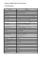
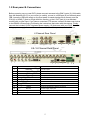
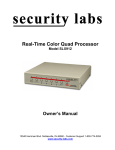
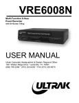
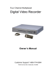
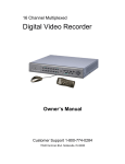
960H Series DVRs User’s Manual Security Labs, Inc. Customer Support 800-774-0294 www.security-labs.com 1 INDEX Chapter One – Product Introduction 1.1 Specifications 1.2 Rear Panel & Connections 1.3 IR Remote Control 1.4 Mouse functions Chapter Two – Initial Setup 2.1 Powering On / Control Menu Bar 2.2 Selecting monitor to display menus 2.3 Setup Wizard Chapter Three – Operation 3.1 Live View 3.2 Recording 3.3 Playback video 3.4 Advanced Playback Options 3.5 Backup Operation 3.6 Controlling a PTZ camera 3.7 Alarm Control 3.8 Display & Camera Adjustments Chapter Four – Main Menu-Making Changes 4.1 Recording Tab 4.1.1 Recording Setup Tab 4.1.2 Channel Overlay 4.1.3 Recording Schedule 4.2 Camera Tab 4.2.1 PTZ Setup 4.2.2 Video Setup 4.2.3 Motion Detection 4.2.4 Sequential Camera Display 4.3 Network Tab 4.3.1 Ethernet (LAN) Setup 4.3.2 PPPoE & 3G (Dial Up) Setup 4.3.3 DDNS 4.3.4 E-mail 4.3.5 Access Control 4.4 System Setup Tab 4.4.1 Time 4.4.2 Hard Drive Management 4.4.3 User Management 4.4.4 Alarm Setup 4.4.5 Output Schedule 4.5 System Management Tab 4.5.1 System Upgrade 4.5.2 Log Search 4.5.3 Online Users 4.5.4 Exceptions (Buzzer Warning) 4.5.5 Default 4.6 Shutdown Chapter Five-Web Browser Connections 5.1 Connecting to the DVR 5.2 System Settings 5.3 Status Control 6.0 Viewing the DVR with PC Software 7.0 Connecting with Smart Phones-Devices 4 4 5 6 7 8 8 8 9 20 20 21 21 23 24 24 26 27 28 28 28 30 30 31 31 32 32 33 34 34 35 36 37 38 38 38 39 40 41 42 43 43 43 44 44 45 45 46 46 48 50 52 52 2 Safety & Precautionary Notes: The power supply of this DVR is provided through a regulated DC12V 5A adapter. Please only use this power supply with your DVR. Do not place the DVR in a place subject to rain or moisture. Do not install the DVR in a place subject to violent vibration. Do not install the DVR in a place subject to direct sunlight, or a high temperature environment. Do not block any vent openings in the case to allow for proper cooling. The DVR shall work under temperature, humidity and voltage according to the limits stated on the technical specifications page. Please keep dust near the unit to a minimum. Proper grounding shall be maintained for safe electrical operation. © Copyright Security Labs, Inc. , 2014. All rights reserved. 3 Chapter ONE Product Introduction 1.1 Specifications Features Description Operating system Embedded LINUX OS Video compression H.264 Video inputs BNC Video (1.0Vp-p,75 Ohm) Video output 1 BNC (1.0Vp-p,75 Ohm), 1 VGA, 1 HDMI Audio 4 RCA In, 1 RCA Out Pentaplex operation Live view, record, network, backup, and mobile phone surveillance. Recording mode Timer/manual/motion detection/alarm Max Recording frame rate 4CH 120 / 8CH 240/ 16CH 480 ips NTSC Recording quality 5 Levels (Highest, High, Common, Low, Lowest) Recording resolution PAL/NTSC 960H(960*576/960*480),D1(720*576/720*480), CIF(352*288/352*240) Recording playback Play, Pause, Stop, Fast forward, Slow forward, Full screen etc. Playback file speed/mode can also be controlled by dragging the progress bar. Recording backup To flash drive, USB external drive, or network. Network transmission Monitor, PTZ control, Playback, System setting, files download, Log information Video Motion Detection Zones: 396 (22 x 18), Sensitivity 1 – 5 (5 = Highest) Email alarm With video motion or optional alarm trigger PTZ control Manual and tour control PTZ protocol PELCO-D & PELCO-P PIP Full screen plus 1 or 2 smaller Zoom Digital – Size and drag with mouse HDD Upgrade Capacity 2 SATA HDD 3TB ea = 6TB Total Network and protocol TCP/IP,UDP,DHCP,DNS,IP filter, PPPOE, E-mail, Alarm server, views UPNP,DDNS,DNS Binding IE browser YES Client software Included Dual stream Main and secondary interchange Multi - User Online access up to 10 users Multi-language 20 Languages Mobile phone surveillance Windows, Symbian, iPhone, Blackberry, Android Network Capture Yes Mouse interface USB2.0 Backup interface USB2.0 Remote control IR User authority Multi-level Power DC12V/3A Working temperature -10℃~ +55℃ Working humidity 10%-90% 4 1.2 Rear panel & Connections Before powering up your new DVR, please connect cameras to the BNC inputs (2), LAN cable from the Network port (7) to your router (or switch), mouse to a USB port (8) on the back panel (TIP: Leave the USB port empty on the front panel for easier backup drive access), and the VGA (6) or HDMI (7) port to a high definition monitor, or the V-OUT jack (4) to a standard monitor with a video input. If you have a motorized PTZ camera, connect its data control wires to the RS485 A-B terminals (9) following the instructions that came with the camera. Finally, connect the included 12VDC regulated power supply (10) that came with your DVR. Caution: Using a power supply from another source can cause erratic operation, or circuit failure. 4 Channel Rear Panel 8 & 16 Channel Rear Panel Item Interface 1 AUDIO IN 4 audio inputs 2 VIDEO IN 4, 8, or 16 video inputs 3 A-OUT 1ch audio output 4 V-OUT Composite video output 5 HDMI HDMI output 6 VGA VGA monitor output 7 NETWORK 8 USB 9 RS485 10 DC-12V Description RJ45 for LAN (local area network) or WAN (internet) Additional mouse and USB backup device ports PTZ (Pan/Tilt/Zoom) camera connection Power supply input jack 11 ALARM INPUTS (Optional on some models) 12 POWER SWITCH Toggle Switch – “OFF” towards outside of chassis 5 1.3 IR Remote control 6 1.4 Mouse Functions To select a menu item Drop a list from a combo box Move a PTZ camera to a selected area Click on a camera in multi-view to make it full screen view 1 To select a character or numeral from an input screen Left button click Displays the shortcut list menu 2 3 Right button click Double click left button To play a file in a list of recorded files Motion Detection Grid Area: Press the left key and drag the mouse to activate 4 Dragging the mouse the squares (green outline) in the camera’s view. Press the right key and drag the mouse to deactivate the squares (black outline). Select and drag a video adjustment bar, or a progress bar during playback. 7 Chapter Two – Initial Setup 2.1 Powering On / Control menu Bar Facing the front of your unit, the main power toggle switch can be easily located by hand in the top left corner of the back panel. Turn on the power switch and allow approximately 45 seconds for the unit to boot up and do a quick check of the hard drive. The DVR will automatically display the Configuration Wizard (first time use), or a colorful control menu bar (pictured below) can be displayed by hovering the mouse pointer near the bottom of the screen. Button Description Button Description Main Menu PTZ Control Wizard & Language Alarm Control Multi Channel Display Setup Recording Control Exit Playback & Backup TIP: To help you notice important points, or scan the instructions for a quick review in the future, buttons or controls that need to be set are printed in BOLD TEXT. 2.2 Menu Display Monitor You can simultaneously use a standard monitor connected to the Video Out jack, and a higher resolution monitor connected to the VGA or the HDMI output. One output will only show the video from your cameras, and can be connected to a public view monitor. The other output will serve as the main control monitor feed and show the video from your cameras, plus the cursor movement of the mouse and all menus that you access. 8 To choose the menu display monitor, click on the <Display Setup> icon at the bottom of the main screen (or right click on the screen to activate the shortcut menu and select <Display Setup>), click the <Setup> tab, select <TV Output> or <VGA Output+HDMI> from the drop list, click <Display Menu>, and confirm your selection by clicking <Yes> now showing on the monitor you have selected. 2.3 Setup Wizard To help guide you through the installation process, this unit is equipped with an interactive setup Wizard. The Wizard can be considered a quick start tool that will help adjust the DVR for most applications. Any settings made using the Wizard can be easily edited later using the Main Menu. To get started, hover the mouse pointer near the bottom of the screen. This will display the control menu tool bar. Click on the second icon from the left. From the first screen of the Wizard, select <Standard User> for a basic installation, or <Professional User> if you plan to use Video Motion Detection, add a PTZ camera, or schedule alarm or e-mail features. The additional professional user menus will be shown in this tutorial. Select from 20 languages that will be displayed on all menus and screen controls. English is the default. Click <Apply> <Next>. TIP: Setting the correct time on your Security Labs DVR is very important. This is the time setting that will be applied to your recorded video, and make your event searches accurate. Set time screen 9 One remote control is included with the DVR. Leave the Remote Control setting at “0” and the Device Name blank. Use the drop list on “Date Mode” to select the date format you prefer. MM/DD/YY is the most popular. Time mode can be set to a typical 12 hour AM/PM format or 24 hour military style. Enter the time and date directly into the boxes on the screen using the mouse and the pop-up letter controls. Once you have established an internet connection, the NTP time server feature can automatically monitor the DVRs time/date settings for you. For now, click on <NTP Setup> and enter the time zone you live in. The GMT zones in the United States are: Eastern -5:00, Central -6:00, Mountain -7:00, and Pacific -8:00. <Apply><Next>. TIP: The most popular hard drive setting is “Recycle” or “Overwrite” Hard Drive Management Screen Once the hard disk drive is full, you need to decide if you want the DVR to stop and wait for your review, or go ahead and keep recording in a loop fashion. Choose the Recycle (overwrite) feature to keep your DVR in a constant record or ready-to-record mode. If you use constant recording versus event recording, “File Time” sets a maximum file size for your recordings to make them easier to backup. 60 minutes is the typical entry. <Apply><Next>. 10 Tip: Select “All” from the Channel droplist for your initial setup. Recording Setup Screen The record setup screen allows you to customize the settings for each camera. The defaults shown will work fine for most situations. If maximizing the period of time covered on the hard drive before overwrite occurs is important, use lower quality, lower frame rates, and CIF (Encoding) for non-critical cameras. Higher quality images with faster frame rates and 960H or D1 encoding use more hard drive space. If you are able to access your DVR to backup an important event within a few days, using higher settings is not an issue. While you are in the record mode, you can check the total number of hours that will be recorded with the “Formatting” feature, further explained in the HD Management section of the Main Menu description. Pre-Alarm <Open> will add a short duration of video prior to a motion or alarm trigger. This will allow you to capture some of the activity prior to an event happening. Select VBR (variable bit recording) encoding for most installations. CBR (constant bit recording) is best used when your internet connection is slower than average. Select Audio “Open” if you have a microphone connected to the channel(s). <Next><Apply> 11 Channel Overlay Screen Again, the defaults shown on this screen will work fine in most situations. The name for each channel is the channel number, and it is displayed in the lower left corner during live video view. The time and date will be displayed in the upper right corner. To change the name of a channel, click on the Channel Name box and follow the prompts. To change the position of any channel name or time on a recording, use the drop list on this menu. <Apply><Next> Tip: Select “All” from the channel drop list if all cameras will have the same schedule Record Scheduling Screen 12 Use your mouse to select the camera(s), type of recording you wish to use, then left-click and drag through the schedule. Normal is a constant recording mode. Motion is the video motion detection mode that will be further detailed in a later step. Select the time periods to operate video motion detection now. Alarm recording (optional feature) controls any external triggers connected to the alarm input terminals. Note: The above example shows normal (constant) recording Monday through Friday from 8:00AM till 6:00PM, and video motion detection at all other times. These would be the settings used by a business with typical weekday hours of operation.<Apply> <Next> Network Setup Screen Please be sure the LAN cable included with your Security Labs DVR is connected from the DVR to your router or network switch. Using your mouse, check DHCP, click <APPLY>, uncheck DHCP, then click <Apply> again. This short procedure will auto fill the boxes on the setup page for you. Write down the following information that you have just collected: IP Address Subnet Mask Default Gateway DNS Server MAC Address Keep this information with the DVR for future reference <Apply><Next> If you selected Standard User at the beginning of the Setup Wizard click <Finish>. Note: You should now be able to access your DVR on a computer that is connected to the same router. This is your Local Area Network (LAN). Type the new IP address of the DVR into the address bar of Internet Explorer. You will be prompted to download an Active X file. This is the viewer program, Client V3, stored in the DVR asking to be installed on your computer. Follow the prompts to complete the installation of Client V3. If you selected Professional User at the beginning of the Wizard, four more setup screens will be shown starting with PTZ Setup. 13 PTZ Setup Screen TIP: Please be sure the twisted pair of communication wires coming from your PTZ camera are connected to the RS485 terminals on the back of the DVR. Proper polarity is important. There are no standard settings for a PTZ camera. What is important is that you match the camera and DVR settings together. Knowing the current or default settings of your PTZ camera will be required for a successful installation. The settings shown on the menu above are the most commonly used, and will operate Security Labs PTZ cameras out of the box. Further details of the available drop list options are shown in the Main Menu description chapter. <Apply><Next> 14 Video Setup Screen The video setup screen allows you to mask an area of any channel from being viewed, and set the notifications that will happen should the video from a camera be lost. Select a channel and click on <Setup> to mask an area from being seen or recorded. Left click and drag the mouse to create a green rectangle over the area, then click <Save & Exit> in the top right corner. To remove the mask, click <Video Setup> from the Main Menu, select the channel involved, click <Setup>, then click the gray edge to the left of the green mask to delete it, then click <Save & Exit>. Check “Buzzer Alarm” or “Send E-mail” if that notification is desired for any selected channel. The default for “Video Mode” is NTSC and should remain so for all regions of North America. Click the <Motion Detection> tab to the right to bring up the screen below. 15 Motion Detection Screen TIP: Always have “Automatic” selected in the Record Control menu for any channel that will use Motion Detection. Video motion detection is an extremely useful feature. Select a channel from the drop list and click <Setup>. Left click and drag the mouse through the picture changing the squares to green (active). To deselect areas not wanted for motion detection, right click and drag the mouse to turn the squares black. Click <Save & Exit> in the top right corner of the camera’s view. Select from one of five sensitivity settings to complete the setup for that channel. Common or lower settings are better suited for outdoor use to help compensate for sudden changes in lighting. In most cases, select the channel from “Trigger Recording” to match the channel you are setting up for motion detection. This will cause only the channel that is viewing activity to be recorded. Check “Buzzer Alarm” or “Send E-mail” if you desire that notification for motion activity. <Apply><Next> TIP: If you create a password for your DVR, please write it down and store it in a safe place. 16 User Management Screen The default user for the DVR is “admin” with no (blank) password. Click on <Admin> then <Edit Password> if you wish to password protect the operation of your DVR. Up to eight users can be assigned to the unit, each with their own set of privileges and private passwords. User names and passwords can be up to eight characters, including letters, numbers, and symbols. To add a user click on <Add User>. TIP: When finishing your session of using the DVR, click <Exit> on the menu bar at the bottom of the screen, then <Logout>. Add User Screen 17 Enter a name, password (twice), then click<Add>. Click on the new name in the User’s list, and check the privileges you wish them to have. Five categories can be selected from the drop list. Click <Save> when you are finished. <Apply><Next> Alarm Setup Screen NOTE: Alarm inputs for connecting the DVR to external triggering devices are optional on some models. Select the channel that you have connected a trigger device to, select *Normal Open or *Normal Closed, and the duration the alarm recording desired. PTZ relate will send instructions to a compatible PTZ camera when an alarm is triggered. Similar to motion recording, check “Send E-mail”, and “Trigger Recording” for the channels that should respond to the alarm, plus “Alarm Output” if you wish to trigger an external device. *Normally Open (NO) = A switch, sensor, or other circuit that triggers an alarm when it is closed (contacts touching). *Normally Closed (NC) = A switch, sensor, or other circuit that triggers an alarm when it is opened (contact separated or wire broken). Click <Output Schedule> to set the hours of the day to send e-mails, for the internal buzzer to sound, or for the alarm output to function if motion detection or an alarm input is triggered. 18 Output Schedule Screen Left click and drag the mouse to select hours of operation (green segments). Right click and drag the mouse to deselect (white segments). <Next><Apply>. TIP: Any feature or option selected during the Wizard setup process can be changed by accessing the Main Menu Final Screen Manual recording will begin on all active channels when you click <Finish>. Deselect <Start Record> to remain in the stop or automatic mode selected earlier. 19 Chapter Three – Operation 3.1 Live View At power up your DVR will automatically go to the live, Multi Channel view mode. To switch to a single camera, select the Multi Channel icon on the control bar. The channel view control will then be displayed. Select the single view box on the top left, and click on the desired channel number to view, or scroll through the live cameras with the forward or reverse arrows. To return to multi-view, click on the multi view box on the top right. Click on “X” to close the control. TIP: Colorful icons are displayed at the top of each channel’s view to show the current status of that channel. 1 Recording 3 Audio On (mic or camera with audio 2 must be connected to DVR 20 Motion Detected 3.2 Recording Click on the Recording Control icon located on the control bar to display the recording control. The recording control (shown below) allows all cameras to be set at once by clicking “All”, or each channel can be selected individually. Automatically = Quickly enables or disables the standby mode for Timer, Video Motion, and Alarm recordings. (Please be sure the recording schedule has been set in the Main Menu.) Manual Rec = Overrides the standby mode and starts a recording on demand. Stop Rec = Ceases the recording in progress. Recording Control as shown on screen 3.3 Playback video 1) Click on the Playback & Backup icon located on the control bar. The playback control (shown below) will then be displayed on your screen. 21 2) Select the date you wish to review (the current date is the default). Dates highlighted with blue contain recordings that can be viewed. Click on a highlighted date, or use the navigation arrows to select another month or year. 22 3) Select the playback time. 3.4 Advanced Playback Options 1. Synchronous / Asynchronous Playback Synchronous mode plays all selected channels (checked on the left side of the playback control) together in real time. Left click on the top of a column of the playback control screen to select all channels in that time period (right click to deselect) and click <PLAY>. All of the channels will display the same recorded time. Using pause, slow motion, or fast forward will affect each channel the same. If no video was recorded on a particular channel at a certain point in time, it will show a blue screen while the other channels continue to play video recorded during that same point in time. Asynchronous mode allows you to select channels (cameras) from different time periods and play them back simultaneously on the same screen. Click on the Lock Icon (#1), a red “X” will appear. Then randomly left click on any square in the playback control screen to select channels and time periods of interest. Click <PLAY> to start. All selected channels will begin playback, each displaying the time its video was recorded. Click on a channel’s view to activate a green outline around it. This will activate the pause, slow motion, and fast forward buttons just for that channel. You can independently pause, play, or adjust the playback speed of all channels. 23 2. Starts playback after selecting time periods to view. 3. Stop button 4. Slow motion speeds of 1/2, 1/4, 1/8, and 1/30. 5. Real time playback 6. Fast forward speeds of 2X, 4X, and 8X. 7. Playback time slide control. Allows you to drag the time indicator across the bottom of the screen to quickly pinpoint the time period you wish to view. Time changes can be seen in the box on the right as you slide the indicator. 8. Audio level control 9. Multi-Channel View selection 10. Display or hide play list 11. Backup menu button 3.5 Backup Operation TIP: If you have not already done so, connect your mouse to the bottom USB port on the back panel of the DVR. This will allow easy access to the front panel USB port for the flash drive backup device. Depending on the file system on your USB flash drive, it may be best to re-boot the DVR with the flash drive installed. Turn the power off on the DVR (facing the DVR, the power switch is located on the top left corner of the back panel), insert the flash drive into the USB slot on the bottom right corner of the front panel, and turn the power back on. Access the playback control screen and select a time period just as you would to play a file as described above, only click on the <Backup> button (11) rather than the Play button (2). Click on the USB drive that appears in the selection screen, and then <Backup Start>. Please wait until the backup counter is finished, and click on <Device Uninstall> before removing the flash drive. An .avi file will automatically be placed on the flash drive with no further conversion needed to play the recording on most computers. 3.6 Controlling a Pan / Tilt / Zoom Camera (PTZ) 24 【Zoom】Controls the optical Zoom IN (+) and Zoom Out (-) of the camera. 【Focus】Manual control of the camera’s focus adjustment if needed. Typically better to set the camera for auto-focusing after operating the zoom control. 【Iris】Aperture size adjustment. Again, in most cases it’s better to use the auto-shutter of the camera. 【Preset】Enter number of preset position to be set or called. Manual Movement Pan or Tilt the camera by left clicking on an area of the screen. You will see a green arrow indicating the direction the camera will move when hovering the mouse pointer on the screen. Left click and move the camera to the area you wish to view, then <+Zoom> for a tighter shot of the area if desired. Programming Preset Positions Click on the <Preset> box and <enter the number> 1. Adjust the pan, tilt, and zoom to achieve the desired view angle for the camera. Click on <Set>. Manually move the camera to another view, enter the number 2 and click <Set>. Continue this process to add more preset positions. To move the camera automatically to a preset position, enter the number of the preset into the box and click <Call>. To delete a preset, enter the number of the preset position and click <Clear>. TIP: When working with tours, use the Set tab to make changes, and the Control tab to operate the PTZ. Tour Set Screen 25 Programming a tour To setup an automatic tour with your PTZ camera, select the Set tab, enter the number 1 in the Set box (for your first tour), and click <Start Tour>. Enter a preset position number in the Preset box and click <Add Preset>. Enter the next preset number and click <Add Preset>. After entering your final preset number, click on <Stop Tour> (the same button location as Start Tour, but changes its name automatically). 【Delete Preset】Will remove set points from a tour 【Clear Tour】Use this command button to delete a tour. PTZ Control Screen 【Tour Scan】To start a tour that you have previously programmed. Enter the number of the tour in the Control box, then click <Tour Scan>. To stop the tour, click <Tour Scan> once again, or <Limit Scan> to stop the tour and return the camera to preset position number one. 【Pattern Scan】An optional Left to Right pan control for certain models of PTZ cameras. 【PTZ Reset】An optional clear memory command for certain models of PTZ cameras. 【Auto Pan】An optional Left to Right pan control for certain models of PTZ cameras. 3.7 Alarm control If your DVR is equipped with optional alarm trigger inputs, use this menu to quickly manage the 26 inputs and output for an alarm condition. 【Set Alarm】Sets the channel in a “standby mode” that will activate a recording when an alarm trigger is detected. 【Clear Alarm】Deactivates the “standby mode”. 【Alarm Output】Select the channel(s) you want to activate the alarm output relay contact. 【All】Allows you to quickly select all channels in the corresponding row. TIP: The Alarm Control is for how the alarm should work. Be sure to configure the alarm inputs and schedule during the initial setup for when the alarm should work. 3.8 Display & Camera Adjustments (1) Video / Monitor The Video adjustment screen gives you control over the signal being recorded. Each channel (camera) can be adjusted by clicking on the screen (high-light green border around channel), select <User-Define> from the drop list, then adjust (in order from left to right): Brightness, Contrast, Saturation (intensity of color), Chroma (tint), and Sharpness. You may also select a preset effect from the drop down list. The arrows to the right of the drop list take the settings back to their default position. Controls on the Monitor tab allow you to adjust the signal that is being fed to the Video Out (TV Output) or to the VGA/HDMI monitor outputs. 27 (2)Setup You can simultaneously use a standard monitor connected to the Video Out jack, and a higher resolution monitor connected to the VGA or the HDMI output. One output will only show the video from your cameras, and can be connected to a public view monitor. The other output will serve as the main control monitor feed and show the video from your cameras, plus the cursor movement of the mouse and all menus that you access. To choose the menu display monitor, select <TV Output> or <VGA Output+HDMI> from the Device drop list, click <Display Menu>, and confirm your selection by clicking <Yes> now showing on the monitor you have selected. The resolution drop list offers five different selections to best match the VGA/HDMI monitor that you may be using. Chapter Four- Main Menu – Making Changes All adjustable features can be found in the Main Menu. Even selections made using the Wizard during initial setup can easily be easily changed using the Main Menu. If you completed the set up process using the Wizard, there are no further adjustments required to use your DVR. The descriptions below are to help you understand the Main Menu and how to make changes to the DVR’s settings. Right click on the screen and select <Main Menu> at the top of the list. 4.1.1 Recording Setup Tab (1) Recording Setup Click this button to adjust items that will affect the quality of your recorded video and the amount of hard drive space that will eventually be used. 28 【Channel】Select “All” to adjust all channels at the same time, or use the drop list to select a particular channel. TIP: Most installations have similar settings for all cameras. Use the “All” selection first, set your parameters, SAVE your settings, then go back and edit individual camera channels to customize the system to your needs. 【Encoding Type】Affects the resolution of the recording. CIF has the lowest resolution, but uses the least amount of hard drive space, D1 is considered “full resolution” and consumes more hard drive space, 960H is an expanded wide screen resolution and consumes the most hard drive space. 【Frame Rate】Select 1 to 30 frames per second. More frames recorded per second requires more hard drive space. Use 30 frames to record fast moving activity or to capture subtle changes. 15 frames per second is fine to capture a person walking without a noticeable jitter, and a few frames per second is enough to notice normal changes in a scene. 【Encoding Mode】CBR (Constant Bit Rate) is used when the internet connection that will transmit the recorded video is slower than normal. VBR (Variable Bit Rate) is the most popular selection, and performs well with most high speed internet connections. 【Image Quality】Image quality is purely a judgment call. Select from five options, again the highest setting consumes the most hard drive space, and the lowest uses the least amount. Most people will start with the highest setting, and eventually lower a non-significant channel if more recording time is preferred before the hard drives overwrites (loop records over older video). 【Pre-Alarm Rec】Is a very useful feature if you are event recording with the video motion or alarm features. Pre-alarm record will store a short segment of video before a trigger (event) occurs, and later show on playback the activity that happened just before the trigger occurred. 【Audio】(Optional) Select “Open” if a microphone or camera with audio is connected to the channel. 29 4.1.2 Channel Overlay – On Screen Display 【Channel】Select a channel to edit the name, or position of the name / time on a recording. 【Channel Name】Click on the Channel Name box and use the pop-up keyboard to enter a name (up to eight characters) for the channel. Click <Save>. 【Channel Display / Time Display】Use the drop lists to change the position of a channel’s name or time on a recording. 4.1.3 Recording Schedule Please note: 0 through 24 denote the hours of the day. The first segment being Midnight through 1:00AM, and the last segment being 11:00PM through Midnight (12:00 AM). Normal Recording will place the DVR into a continuous recording mode for the time period selected. Motion and/or Alarm recording are only allowed to operate during the time periods you select for them. 30 Select a channel (or “All”) to modify, click on the type of recording you wish to use, left click and drag your mouse through the time segment to set the schedule, click SAVE when finished. 4.2 Camera Use this tab to access settings for a PTZ camera, areas to block from the view of a camera, adjust video motion detection, and sequential camera viewing. 4.2.1 PTZ Setup There is no industry standard for the default settings used by a PTZ camera. The settings shown above are the most popular and are the default settings for a Security Labs PTZ camera. The task here is to match the settings in the DVR to the settings used by your PTZ camera. If you are connecting more than one PTZ camera, remember to assign each camera a unique address (Ex: 1, 2, or 3). The DVR uses this address to communicate with the camera you wish to control. 31 4.2.2 Video Setup 【Video Mode】NTSC mode is the default setting for North America and this unit. 【Channel】Select a channel to modify the settings below. 【Reserved Section】Click on the Setup button, left-click and drag your mouse over any area that you want to hide from a camera’s view. Remember to SAVE your changes using the icon on the top right corner of the screen. 【Video Loss】The video loss feature will notify you in the event a camera fails or is disconnected. Select the channel (or All) and click on Buzzer Alarm (the DVR’s internal warning buzzer), and/or Send E-mail (remember to enter your e-mail account information in the Network section). You can also click on the Alarm Output #1 to activate the external alarm output relay (optional on some models). 4.2.3 Motion Detection 32 【Channel】Select a channel to add or modify video motion detection settings. 【Sensitivity Setting】Choose from five selections. TIP: Cameras mounted outdoors can be false triggered by changes in daylight from fast moving clouds, large insects crawling on a camera’s lens, or by car headlights at night. Consider these factors when placing your cameras; use lower sensitivity settings with outdoor cameras and target only the important items in a camera’s view with the detection area settings. 【Detection Area】A very useful feature when setting motion detection with your DVR. Motion in front of the green squares will trigger the DVR, while motion in front of the gray squares will be ignored. Click on the <Setup> button, left-click and drag to turn the squares on the grid green (On), right-click and drag to turn the squares gray (Off). Click on the SAVE icon at the top right of the screen to save or exit without saving. 【Trigger Recording】This feature allows you to select the channel(s) you wish to record if motion is detected by the channel you are editing. You can choose to have just the channel you are editing perform a recording, or have several channels record if this channel is triggered. Similar to the Video Loss feature, you can set the DVR to notify you with the internal buzzer, e-mail, or external alarm (if equipped) by clicking the appropriate boxes. 4.2.4 SEQ Display The sequential channel display gives you the option to animate your display of cameras. Click on the <SEQ Display> button, enter a duration time to view each screen (from 5 to 256 seconds), and click on the individual channels and/or quad + displays to be viewed and <Save> your changes. To start or stop the sequential display, right click on the screen to display the shortcut menu, and click on the SEQ Display text. 33 4.3 Network Setup Tab 4.3.1 Ethernet (Local Area Network) Setup 【DHCP】”Dynamic Host Configuration Protocol”. If this is checked your network will automatically assign your DVR an IP address when it connects. It will also assign it the proper subnet mask, default gateway, and DNS “Domain Name Server” address. Using your mouse, check DHCP, click <APPLY>, uncheck DHCP, then click <Apply> again. This short procedure will auto fill the boxes on the setup page for you. Write down the following information that you have just collected: IP Address Subnet Mask Default Gateway DNS Server MAC Address Keep this information with the DVR for future reference. Note: You should now be able to access your DVR on a computer that is connected to the same router. This is your Local Area Network (LAN). Type the new IP address of the DVR into the address bar of Internet Explorer. As shown above, you would type: 192.168.0.19 into the IE address bar. You will be prompted to download an Active X file. This is the viewer program, Client V3, stored in the DVR asking to be installed on your computer. Follow the prompts to complete the installation of Client V3. To access the DVR remotely over the WAN (aka internet), you will need to configure your router to allow access to the DVR from internet. Typically, you will need to “port forward” the DVR HTTP port. This allows the router to automatically send requests to your DVR when you connect remotely. For more information on port forwarding, go to portforward.com or call Security Labs customer service to help you configure your system. 【UPnP】”Universal Plug and Play” When checked, the DVR will send discovery information to the network. The efault setting for UPnP is off. 【IP Address】 This is the LAN “Local Area Network” address of the DVR. It is important to know this address when connecting to the DVR from the LAN or WAN “Wide Area Network” 34 The WAN is also often called the ‘Internet’. Each device (computers, cell phones, etc) on your LAN has a unique IP address. 【Subnet Mask】 Server subnet mask. All devices on your LAN need to have the same subnet mask in order to communicate with each other. 【Default Gateway】 Server gateway. This is typically the same IP address as the router on your system and allows the DVR to communicate to the WAN or internet. 【DNS Server】 DNS server addresses. The “Domain Name Server” is an address that contains a list that enables a device to translate domain names into numbers. People use words to navigate the internet; machines use numbers. 【Server Port】 Data port, initial socket is 7777. This is the port that allows the DVR to send data and video. 【HTTP Port】”Hyper Text Transfer Protocol” Port. This is the port your computer or mobile device browser uses to view web pages. The default port for browsers is 80. If you wanted to connect to 192.168.1.1 on port 80, you would just type 192.168.1.1. The ‘80’ is the default and you don’t have to enter it. If you change the DVR port to another number, like ‘81’ you will need to enter the port in your browser address: 192.168.1.1:81 (the port follows the IP address with a colon in front of it). Changing the DVR port is helpful when setting up internet or WAN remote viewing for the DVR. 【Handset Port】This is the port your mobile phone or other mobile smart device can use to access the DVR, initial socket is 8888. This number is used in the setup screen on your mobile device. 4.3.2 PPPoE & 3G (Dial-UP Setup) PPPoE “Point to Point Protocol over Ethernet” This configuration setup is for infrequently used systems that connect using a 3G network card and a local network. 1) Automatic Dialing (Dial type PPPoE) Select the PPPoE in the interface along with your account and password of the 3G card in your network. 2) Manual Dialing (Dial type 3G) 35 You will need to provide the APN “Access Point Name”, the connection number, the account, and password. These items are avaialble from your 3G card service provider. 4.3.3 DDNS Setup 【DDNS Service】”Dynamic Domain Name System” Is helpful if your IP address is dynamic and not static. A static address is assigned by your service provider and does not change. A dynamic address is the most widely used service and can change. A DDNS service can track your dynamic address and allow you to always connect to it. If you would like to use this service, go to www.dyndns.org and sign up for an account. Enter the account information in the DVR DDNS set up tab. 36 4.3.4 E-mail 【SSL Protocol】”Secure Socket Layer” Check this box only if your email server requires it to connect. 【Email Address】The recipient's email address. There are two boxes for two recipients. 【Send Email】The sender’s email address . 【SMTP Server】”Simple Mail Transfer Protocol” server. The server, designated by your service provider, is used to send mail. Your smtp server may look like “mail.mydomain.com” or “pop.maildomain.com” 【Email Account】Your login name for the email account. Many providers use your full email address as the name. 【Email Password】The password to your email address. 【Test Email】Send an email to the recipient (s) mailbox(es) for testing to see if the settings are correct. Normally you can check your email account for the settings above. Email alerts can be sent under the following conditions: 【input alarm】and 【video loss】 These two types of alarms must be enabled in ALARM SETUP, MOTION DETECTION SETUP and/or VIDEO SETUP for an email to be sent. 37 4.3.5 Access Control 4.3.5 Access Control Determines which computers have access to your DVR. 【List Rule】Default is “not used”. With the table, you can refuse or grant access to your DVR based on the computer’s IP address. 【Starting IP】Display starting IP address of a group of addresses you are selecting. 【Ending IP】Display ending IP address of a group of addresses you are selecting. 【Add】ADD the IP address string placed in the “starting IP’ and ‘ending IP’. 【Delete】DELETE the IP address string placed in the “starting IP’ and ‘ending IP’. 4.4 System Setup 4.4.1 Time 38 【Remote Control – Device Name】If only using 1 or no remote controls leave the Remote Control setting at “0”, and the Device Name blank. 【Date Mode】Select the date format you prefer to use. 【Time Mode】Choose from 12 hour (AM-PM), or 24 hour time format 【System Date / Time】Click on these items to manually enter the date and time. Click <Set Time> when finished. 【Daylight-saving mode】Check the DST box if observed in your area. 【NTP Setup】The time setting can be synchronized with a Network Time Protocol (NTP) server on the internet. This feature will automatically update your clock on a regular basis to insure an accurate time display on your recordings. After clicking on <NTP Setup>, continue to use the default time server or add your own. Be sure to enter your local time zone using the drop list. The GMT zones in the United States are: Eastern -5:00, Central -6:00, Mountain -7:00, and Pacific -8:00. Click <Save> when you are finished. 4.4.2 HDD Management 【Disk Full】Once the hard disk drive is full, you need to decide if you want the DVR to stop and wait for your review or go ahead and keep recording in a loop fashion. Choose the Recycle (overwrite) feature to keep your DVR in a constant record or ready-to-record mode. 【File Time】Divides constant recordings into segments that can be more easily transferred to a backup file. 60 minutes is a typical entry. 【Recording Bit-rate】 Unit must be in record mode. Clicking on “Formatting” shows the current bit rate of all active channels being recorded. You can select any (or all) channels with the manual recording feature to monitor the current bit rate (bits of data per second) being recorded. 【Recording Time】Unit must be in record mode. Clicking on “Formatting” shows the maximum hours that can be recorded with all active channels. You can select any (or all) channels with the manual recording feature to see how many hours can be recorded using the hard disk drive that you have installed in the DVR. Fluctuations in the total recording time are caused by changes in the view of any camera (motion). Actively changing scenes require more hard drive space than static scenes with little or no changes. If you find that more total recording time is required than you have allotted for you can lower the frame rate, resolution, or 39 quality of any camera to gain more available hours on your hard drive. 【Formatting】Click this button during record mode to show the current bit rate and recording time for one cycle (loop) of the hard drive. If you would like to format the hard drive (erase all data) stop all recording and highlight the drive in the list by clicking on its name. A blue highlight will be displayed over the drive’s name to show it has been selected, then click on “Formatting”. You will be asked to confirm your selection. THIS FUNCTION WILL ERASE ALL DATA FROM YOUR HARD DRIVE. Formatting the hard drive can be useful to improve performance of the unit if the DVR’s clock is changed, an excessive amount of events have been recorded and stored, or if a power surge has affected your equipment. 4.4.3 User Management Use this menu to set up user names, passwords, and privileges allowed for each person. 【User】Up to eight users can be assigned to operate the DVR. Each user name can have up to eight characters. 【System Privileges】Choose from five drop lists of options. 【Add / Delete / Edit】All user names and passwords (up to 8 characters) can be edited by the Administrator by clicking on the buttons at the bottom of the screen. 4.4.4 Alarm Setup Use this menu to set up the parameters for the alarm inputs and output. TIP: Be sure to set the Recording Control in the shortcut menu to “Automatically” to activate the alarm trigger feature. 40 【Alarm Input】Similar to other setup menus, select a channel to modify (or All). 【Input Type】All alarm trigger switches or devices are categorized as: Normally Open (NO) = A switch, sensor, or other circuit that triggers an alarm when it is closed (contacts touching). Normally Closed (NC) = A switch, sensor, or other circuit that triggers an alarm when it is opened (contact separated or wire broken). Set each channel for the type of device that is connected to the alarm input terminal on the back of the DVR. If no device is connected to a channel, leave the input type for that channel as Normally Open (NO). 【Clear Alarm】Use the drop list to select a time period for the duration of an alarm recording. 【PTZ Relate】If you have a compatible PTZ camera model, when an alarm is triggered a selected point or tour can be initiated. Click on <Setup> to make your selection from the preset positions or tours that you previously created under PTZ Control in the shortcut menu list. 【Trigger Recording】Select any combination of channels you wish to record when the alarm is triggered for the channel you are working with. 【Alarm Output】Click to light up the button and make the alarm output relay active for this channel. 41 4.4.5 Output Schedule Left click and drag your mouse to quickly select the time periods of the day when you want the internal buzzer, e-mail, and alarm output functions to operate. <Save> when finished making your selections. 42 4.5 System Management 4.5.1 System Upgrade Rarely is a software upgrade needed for your unit. Should you experience any unusual symptoms with your unit, please contact Security Labs customer service at 1-800-774-0284 for help. 4.5.2 Log Search A text database log is kept for Control, Setup, Alarms, and Operational Errors. The date search box and drop list are there to help you find the information you want faster. 43 4.5.3 Online Users Click <Online Users> to show a list of user names and their IP addresses that are currently connected to the DVR via a LAN or WAN (internet) connection. The Administrator also has the option to disconnect a current user. 4.5.4 Exception Handling (Buzzer Warning) Exception handling is a feature that enables you to set the internal warning buzzer to activate in the event of a problem with the hard drive, other hardware (circuit), or a network failure. Use the drop list to select Disk, Hardware, or Network Error, and select a time period for the buzzer to operate if a problem is detected. 44 4.5.5 Default This DVR series has the unique ability to return groups of settings back to the factory default (versus the entire unit). Select the group (or All) that you wish to return the factory default, click <Restore Settings>. Click <OK> and <Exit>. Note: Language, time date format, video format, IP address, and user accounts will not be restored. 4.6 Shutdown Safe mode for Shutdown Click <Exit> on the bottom tool bar, then <Power Down> on the pop up. The power switch can be turned off directly but safe mode is less disruptive to the hard drive. 45 Chapter FIVE: Web Browser Connections 5.1 Connecting to the DVR The web browser viewing utility supports multiple browsers. Using Internet Explorer (IE), Google Chrome, or Firefox, enter the IP address of your DVR into the address bar of the browser (near the top of the window). When IE connects to your DVR, you will be prompted to download or run ‘NetDVR3 ActiveX Control Module’. Click yes or allow. This will enable your browser to connect to the DVR. You can also install the ActiveX directly from the CD that came with your DVR. Open the folder on the CD named ‘3) PC Client with Multi-Browser Support’ and double click ‘NetDvrV3.exe’ to install the program. The following screen will appear (without the specific data shown): 46 By clicking on the ‘Net Search’ tab, you can have the program automatically search for your DVR on the local network. You can also enter the IP address manually into the ‘IP address’ box. The default port (unless it has been changed on the DVR) is 7777. The default User Name is: admin. The default password is left blank (no password). These settings can be changed in the DVR menu under SYSTEM SETUP/USER MANAGEMENT. Users can be assigned individual privileges in the menu. Click the ‘Login’ button to go to the viewing screen. At the bottom of the screen, choose how many camera/windows you wish to view simultaneously. 47 5.2 System Settings Click the ‘Setup’ button on the right panel to enter the configuration screen. Tabs are provided for each of the different sections. When choosing enable boxes, a left click on the box will enable (green) and a right click will disable (white). To set a folder to keep recordings from the DVR on your computer hard drive, click the box with three dots on it to the right of the directory path (under Record Setting). Choose the folder on your PC. Use the same technique to choose the ‘capture image’ folder. Always click the ‘SAVE” button after making changes. 48 If you have a Pan-Tilt-Zoom (PTZ) camera connected to your DVR, you can set the PTZ protocol under the ‘PTZ Setting’ tab. Refer to the PTZ camera manual for the correct protocol and programming for each box. The PTZ camera can be controlled from the view screen. 49 The ‘Alarm Setting” tab allows you to determine which channels (cameras) will enable the DVR to go into record when an alarm input on the back of the DVR is active. An alarm input is different than the motion detection input. An alarm input could be a PIR motion detector, door switch, or other device. Left click on the channel (1-4 for a 4 CH DVR) to enable that camera to put the DVR into record. If you are using a PTZ camera, you can set it to go into a tour or preset position when an alarm is detected. Click on the ‘Alarm Relate PTZ’ next to the channel you wish to use and choose the preset you desire. 5.3 Status Control In the main viewing window, click on the ‘Control’ box on the right side of the panel. The tabs provide settings for video control, the current users connected to the DVR, as well as alarm and record control settings. You can also reboot, shutdown, or upgrade the firmware in the DVR. 50 51 6.0 Viewing the DVR with PC Software (without a web browser) Included on the CD that came with your DVR is a ‘stand alone’ PC program that can connect to your DVR. This program is identical to the web browser viewing program described in the previous chapter (5.0). If you would like to avoid using a web browser or simply would like to use this program, it can be installed by opening the folder named ‘2) PC Client Viewing Software’ on the CD. Double click on ‘NetDvrV3.exe’ to install the program. Follow the set up configuration instructions found in Chapter Five. 7.0 Connecting with a Smart Phone Asee Mobile Viewing Program The recommended app for remote viewing via a smart phone or tablet is the Asee platform by MEye Tech. The apps are constantly being updated and online help comes with the app. On the CD that is provided with the DVR, you will find the apps to install on your Android, BlackBerry, and Symbian OS phones. For the iPhone, the program must be downloaded from the iTunes store (free). The PORT# you will use for all mobile app connections is ‘8888’ (default) or the port you have configured in the menu settings on the DVR. 52 Open the CD on your computer and open the folder named “Mobile Client”. In this folder are the mobile viewing programs for Android, BlackBerry, and Symbian. iPhone Instructions: Click on App Store icon on your iPhone or iPad. Seach for ASee+, download, and follow the instructions provided with the app to connect remotely to your DVR. Android Instructions: Search ASee+ on the Marketplace and install the free download. This will install the most current version of the app on your smart device. You may also install the program offline by copying the ‘Asee.apk’ file in the Android folder to your phone via the phone cable. After installing the program, follow the online help to connect to your DVR. BlackBerry Instructions: Install ASee.cod and ASee.alx files found on the CD in the BlackBerry folder. Use the BlackBerry device manager to install these files. Once the program is installed on your BlackBerry, use the help files contained within the app to connect to your DVR. 53 Symbian Instructions: Search ASee+ on the Marketplace and install the free download. This will install the most current version of the app on your smart device. You may also install the program offline by copying the ‘Asee.sisx’ file in the Symbian folder to your phone via the phone cable. After installing the program, follow the online help to connect to your DVR. . 54 Security Labs, Inc. Limited Product Warranty DVR: ONE YEAR PARTS AND LABOR – HARD DRIVE: MAY VARY WITH MODEL. Should this product proves to be defective in material or workmanship under normal usage, we will provide without charge to the consumer, parts and/or labor necessary to remedy the defect for the period of ONE YEAR from the date of purchase. The warranty period commences on the date that the product is purchased by the consumer. Any implied warranty is also limited to the duration above. THIS WARRANTY DOES NOT COVER THE FOLLOWING: FLUCTUATIONS IN THE POWER SOURCE OR LIGHTNING-RELATED DAMAGE; ATTACHED OR UNATTACHED ACCESSORIES; COSMETIC PARTS SUCH AS KNOBS AND ACCESS DOORS; CABINET DAMAGE, INCLUDING DAMAGE IN TRANSIT; ACCIDENTAL DAMAGE; MISUSE; ABUSE; UNAUTHORIZED PARTS USAGE OR REPAIRS; RECEPTION PROBLEMS DUE TO INADEQUATE SIGNAL; UNAUTHORIZED INTERNAL CONTROL OF ADJUSTMENTS; INSTALLATION; ADJUSTMENT OF CONSUMER CONTROLS; OR ANY OTHER USE OF THE PRODUCT OTHER THAN THAT SPECIFICALLY PRESCRIBED IN THE OWNER'S MANUAL. THIS WARRANTY APPLIES TO PRODUCT SOLD AS NEW AND NOT REMANUFACTURED, RECERTIFIED, OR B STOCK PRODUCTS. THE USER/OWNER OF THIS PRODUCT ASSUMES ALL LIABILITY FOR ANY VIOLATION OF PRIVACY FROM ILLEGAL RECORDINGS MADE ON THIS UNIT. THE USER/OWNER ASSUMES FULL LIABILITY FOR ANY AND ALL RECORDINGS MADE FROM THIS UNIT IN A SECURITY OR SURVEILLANCE OPERATION OR IN ANY OTHER USE. THE MANUFACTURER IS NOT RESPONSIBLE FOR RECORDINGS THAT VIOLATE LAWS OR THAT MAY PROVE OFFENSIVE OR TEND TO INCRIMINATE ANOTHER INDIVIDUAL. LOCAL, STATE, AND FEDERAL LAWS MUST BE OBSERVED REGARDING ALL RECORDINGS. To obtain warranty service, the consumer must provide the product along with evidence that will positively identify the date that the product was purchased from an authorized product representative, dealer, retailer, or distributor. Prior to shipment, a RETURN AUTHORIZATION must be obtained; this will assist us in more efficient service on your unit, and possibly avoid shipment if the adjustment can be made over the phone. If shipment is made, the cost for postage, insurance and shipping of the product is the responsibility of the owner. THE MANUFACTURER’S OBLIGATION UNDER THIS WARRANTY SHALL BE TO REPLACE SUCH PARTS AND PROVIDE LABOR AS STATED. THE MANUFACTURER WILL NOT BE LIABLE FOR ANY LOSSES OR INCONVENIENCES DIRECT OR INDIRECT, OR CONSEQUENTIAL PROPERTY DAMAGES. To obtain a warranty return authorization number, contact our Customer Service at: Security Labs, Inc. 15540 Herriman Blvd.. Noblesville, IN 46060 Customer Service 1-800-774-0284 55