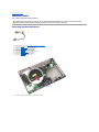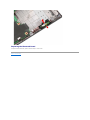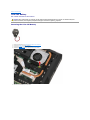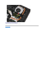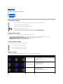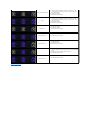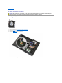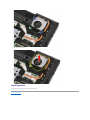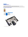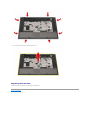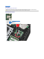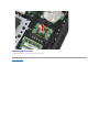
1
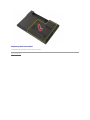
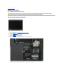
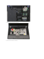
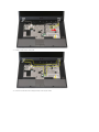
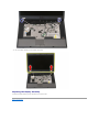
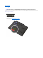
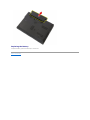
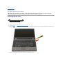
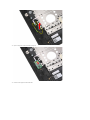
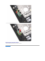
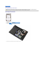
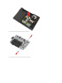
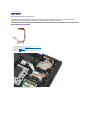
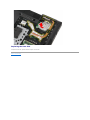
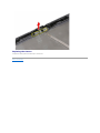
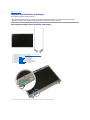
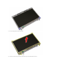
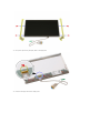
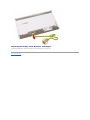
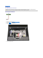
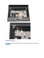
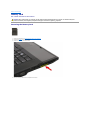
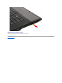
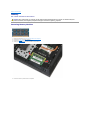
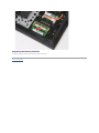
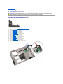
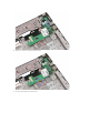
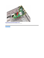
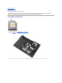
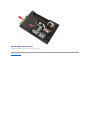
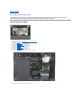
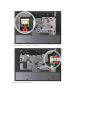
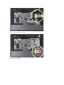
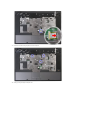
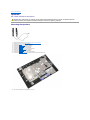
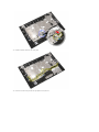
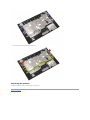
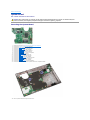
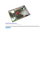
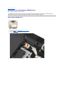
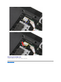
Dell™ Latitude™ E5510 Discrete Service Manual Working on Your Computer
Adding and Replacing Parts
Specifications
Diagnostics
System Setup
Notes, Cautions, and Warnings
NOTE: A NOTE indicates important information that helps you make better use of your computer.
CAUTION: A CAUTION indicates potential damage to hardware or loss of data if instructions are not followed.
WARNING: A WARNING indicates a potential for property damage, personal injury, or death.
If you purchased a Dell™ n Series computer, any references in this document to Microsoft® Windows® operating systems are not applicable.
Information in this document is subject to change without notice.
© 2010 Dell Inc. All rights reserved.
Reproduction of this material in any manner whatsoever without the written permission of Dell Inc. is strictly forbidden.
Trademarks used in this text: Dell, the DELL logo, Latitude, Wi-Fi Catcher, and ExpressCharge are trademarks of Dell Inc.; Intel, Pentium, Celeron, a n d Core are either trademarks or
registered trademarks of Intel Corporation; Bluetooth is a registered trademark owned by Bluetooth SIG, Inc. and is used by Dell under license; TouchStrip is a trademark of Zvetco
Biometrics, LLC; Blu-ray Disc is a trademark of the Blu-ray Disc Association; Microsoft, Windows, Windows Server, MS-DOS, Aero, Windows Vista, Windows XP, Windows 7 and the
Windows Vista, Windows 7 and the Windows Vista start button are either trademarks or registered trademarks of Microsoft Corporation in the United States and/or other countries.
Other trademarks and trade names may be used in this document to refer to either the entities claiming the marks and names or their products. Dell Inc. disclaims any
proprietary interest in trademarks and trade names other than its own.
June 2010 Rev. A00
Back to Contents Page
Access Panel
Dell™ Latitude™ E5510 Discrete Service Manual
WARNING: Before working inside your computer, read the safety information that shipped with your computer. For additional safety best
practices information, see the Regulatory Compliance Homepage at www.dell.com/regulatory_compliance.
Removing the Access Panel
1.
2.
3.
Follow the procedures in Before Working Inside Your Computer.
Remove the battery.
Loosen the screw that secures the access panel to the computer.
4.
Slide out the access panel away from the computer and remove it.
Replacing the Access Panel
To replace the access panel, perform the above steps in reverse order.
Back to Contents Page
Back to Contents Page
Display Assembly
Dell™ Latitude™ E5510 Discrete Service Manual
WARNING: Before working inside your computer, read the safety information that shipped with your computer. For additional safety best
practices information, see the Regulatory Compliance Homepage at www.dell.com/regulatory_compliance.
Removing the Display Assembly
1.
2.
3.
4.
5.
6.
7.
Follow the procedures in Before Working Inside Your Computer.
Remove the battery from the computer.
Remove the access panel from the computer.
Remove the WLAN card from the computer.
Remove the LED cover from the computer.
Remove the keyboard from the computer.
Disconnect the wireless antennas and remove them from their routing paths.
8.
Remove the screws securing the bottom of the display assembly to the computer.
9.
10.
Disconnect the display data cable from the system board.
Disconnect the camera cable from the system board.
11.
Release the cables from the routing path.
12.
Remove the screws that secure the display assembly to the computer chassis.
13.
Lift up the display assembly from the computer and remove.
Replacing the Display Assembly
To replace the display assembly, perform the above steps in reverse order.
Back to Contents Page
Back to Contents Page
Battery
Dell™ Latitude™ E5510 Discrete Service Manual
WARNING: Before working inside your computer, read the safety information that shipped with your computer. For additional safety best
practices information, see the Regulatory Compliance Homepage at www.dell.com/regulatory_compliance.
Removing the Battery
1.
2.
Follow the procedures in Before Working Inside Your Computer.
Slide the battery release latch into the unlocked position.
3.
Remove the battery from the computer.
Replacing the Battery
To replace the battery, perform the above steps in reverse order.
Back to Contents Page
Back to Contents Page
Bluetooth Board
Dell™ Latitude™ E5510 Discrete Service Manual
WARNING: Before working inside your computer, read the safety information that shipped with your computer. For additional safety best
practices information, see the Regulatory Compliance Homepage at www.dell.com/regulatory_compliance.
Removing the Bluetooth Board
1.
2.
3.
4.
5.
6.
7.
8.
9.
10.
Follow the procedures in Before Working Inside Your Computer.
Remove the battery from the computer.
Remove the access panel from the computer.
Remove the optical drive from the computer.
Remove the LED cover from the computer.
Remove the keyboard from the computer.
Remove the display assembly from the computer.
Remove the LED board from the computer.
Remove the palm rest from the computer.
Disconnect the Bluetooth board cable.
11.
Release the Bluetooth board from the latches and remove it.
Replacing the Bluetooth Board
To replace the Bluetooth board, perform the above steps in reverse order.
Back to Contents Page
Back to Contents Page
System Setup
Dell™ Latitude™ E5510 Discrete Service Manual <F12> Menu
Entering System Setup
Boot Menu
Drive BIOS Quicktest
Navigation Keystrokes
System Setup Menu Options
Your computer offers the following BIOS and System Setup options:
l
l
l
Access System Setup by pressing <F2>
Bring up a one-time boot menu by pressing <F12>
Start the Pre-boot System Assessment by pressing <Fn> and the power button
<F12> Menu
Press <F12> when the Dell™ logo appears to initiate a one-time boot menu with a list of the valid boot devices for the computer. Diagnostics and Enter Setup
options are also included in this menu. The devices listed on the boot menu depend on the bootable devices installed in the computer. This menu is useful
when you are attempting to boot to a particular device or to bring up the diagnostics for the computer. Making changes in the boot menu does not make any
changes to the boot order stored in the BIOS.
Entering System Setup
Press <F2> to enter System Setup and make changes to user-definable settings. If you have trouble entering System Setup using this key, press <F2> when
the keyboard lights first flash.
Boot Menu
Your computer features an enhanced one-time boot menu:
l
l
l
Easier access—Access the menu by pressing <F12> during system boot.
User prompting—The missing keystroke is now displayed on the BIOS splash screen.
Added diagnostics options—The boot menu now includes two new options: IDE Drive Diagnostics (90/90 hard drive diagnostics) and Boot to the
Utility Partition.
Drive BIOS Quicktest
The Drive BIOS Quicktest allows you to test the physical functionality of the hard drive without having to locate and download files from support.dell.com or
make bootable floppies or CDs. Select IDE Drive Diagnostics from the boot menu to initiate the test.
Navigation Keystrokes
Use the following keystrokes to navigate the System Setup screens.
Navigation Keystrokes
Action
Keystroke
Expand and collapse field
<Enter>, left- or right-arrow key, or +/–
Expand or collapse all fields
<>
Exit BIOS
<Esc>—Remain in Setup, Save/Exit, Discard/Exit
Change a setting
Left or right-arrow key
Select field to change
<Enter>
Cancel modification
<Esc>
Reset defaults
<Alt><F> or Load Defaults menu option
System Setup Menu Options
The following tables describe the menu options for the System Setup BIOS.
General
Option
Description
This section lists the primary hardware features of your computer. There are no configurable options in this section.
l
System Information
¡ BIOS Version
¡ Service Tag
¡ Asset Tag
¡ Ownership Tag
l
l
System
Information
l
Battery
Information
¡ Manufacture Date
¡ Ownership Date
Memory Information
¡ Memory Installed
¡ Memory Available
¡ Memory Speed
¡ Memory Channel Mode
¡ Memory Technology
¡ DIMM A Size
¡ DIMM B Size
Processor Information
¡ Processor Type
¡ Core Count
¡ Processor ID
¡ Current Clock Speed
¡ Minimum Clock Speed
¡ Maximum Clock Speed
Device Information
¡ Primary Hard Drive
¡ Modular Bay Device
¡ System eSATA Device
¡ Dock eSATA Device
¡ Video Controller
¡ Video BIOS Version
¡ Video Memory
¡ Panel Type
¡ Native Resolution
¡ Audio Controller
¡ Modem Controller
¡ Wi-Fi Device
¡ Cellular Device
¡ Bluetooth Device
Indicates the primary battery and the media bay battery status. Also displays the type of AC adapter connected to the computer.
The computer attempts to boot from the sequence of devices specified in this list:
l
l
l
l
Boot
Sequence
l
l
Diskette drive
Internal HDD
USB Storage Device
CD/DVD/CD-RW Drive.
Cardbus NIC
Onboard NIC
This list specifies the order that the BIOS searches devices when trying to find an operating system to boot. To change the boot order, select
the device to be changed in the list then click the up/down arrows or use the keyboard PgUp/PgDn keys to change the boot order of the
device. The boot devices can also be de-selected from the list using the checkboxes. This is also where the UEFI boot option can be enabled
or disabled.
Date/Time
Displays current date and time settings.
System Configuration
Option
NOTE:
Description
The System Configuration group contains options and settings related to integrated system devices. (Depending on your computer and
installed devices, the items listed in this section may or may not appear.)
Enables or disables the onboard LAN controller.
Integrated NIC
Default setting: Enabled w/PXE
System
Management
Controls system management mechanism. The setting options are Disabled, Alert Only, and ASF 2.0.
Default setting: ASF 2.0
This field determines how the parallel port on the docking station operates. The setting options are Disabled, AT, PS/2, and ECP.
Parallel Port
Default setting: AT
This field determines how the integrated serial port operates. The settings are Disabled, COM1, COM2, COM3, and COM4.
Serial Port
Default setting: COM1
This option configures the operating mode of the internal SATA hard drive controller. The settings are Disabled, ATA, and AHCI.
SATA Operation
Default setting: AHCI
Use the checkboxes to enable/disable the following devices:
l
l
l
Miscellaneous
Devices
l
l
l
l
l
Internal Modem
Modular Bay
Media Card, PC Card, and 1394
External USB Port
Microphone
Camera
eSATA Ports
Hard Drive FreeFall Protection
Default setting: All enabled.
Video
Option
LCD Brightness
Description
This option (represented by a slider bar for On Battery and On AC) sets the panel brightness when the ambient light sensor is off.
Security
Option
Description
This field lets you set, change, or delete the administrator (admin) password (sometimes called the "setup" password). The admin
password enables several security features when set including:
l
l
l
Admin Password
l
Restricts changes to the settings in Setup.
Restricts the boot devices listed in the <F12> Boot Menu to those enabled in the "Boot Sequence" field.
Prohibits changes to the owner and asset tags.
Substitutes for the system password if the system prompts for a password during power on.
Successful changes to this password take effect immediately.
If you delete the admin password, the system password is also deleted. Also, the admin password can be used to delete the HDD
password. For this reason, you cannot set an admin password if a system password or HDD is already set. The admin password must be
set first if used in conjunction with a system and/or HDD password.
System
Password
This field lets you set, change, or delete the system password (previously called the "Primary" password).
Internal HDD
Password
This field lets you set, change, or delete the password on the system's internal hard disk drive (HDD). Successful changes take place
immediately and require a system restart. The HDD password travels with the hard drive, so the HDD is protected even when installed in
another system.
Password Bypass
This option lets you bypass the system and internal HDD password prompts during a system restart or when resuming from a standby
state. Settings are Disabled and Reboot Bypass.
The system will always prompt for the set system and internal HDD password when powered on from an off state (cold boot).
Password
Change
This option lets you determine whether changes to the System and HDD passwords are permitted when an Admin password is set. Use
the checkbox to allow or disallow changes.
This option lets you control whether the Trusted Platform Module (TPM) in the system is enabled and visible to the operating system.
When disabled (checkbox is empty), the BIOS will not turn on the TPM during POST. The TPM will be non-functional and invisible to the
operating system. When enabled (checkbox filled), the BIOS will turn the TPM on during POST so it can be used by the operating system.
Disabling this option does not change any settings you may have made to the TPM, nor does it delete or change any information or keys
you may have stored there. It simply turns off the TPM so that it cannot be used. When you re-enable the TPM, it will function exactly as
it did before it was disabled.
TPM Security
Once TPM is enabled (checkbox filled), the available settings are: Deactivate, Activate, and Clear.
With the TPM in Deactivate mode it will not execute any commands that use the resources of the TPM, nor will it allow any access to
stored owner information.
The Clear setting allows the owner information stored in the TPM to be cleared. Use this to restore the TPM to its default state if you lose
or forget the owner authentication data.
Computrace®
This field lets you activate or disable the BIOS module interface of the optional Computrace software. The settings are Deactivate,
Disable, and Activate.
The Activate and Disable options will permanently activate or disable the feature and no further changes will be allowed.
This field enables or disables the Execute Disable mode of the processor. Use the checkbox to enable / disable this feature.
CPU XD Support
Default setting: Enabled
This option lets you determine whether changes to the setup option are permitted when an administrator password is set. If disabled,
Non-Admin Setup
the setup option is locked by the admin password. It cannot be modified unless setup is unlocked. Use the checkboxes to allow / deny
Changes
access to the Wi-Fi Catcher Changes and / or Wireless Switch Changes within the system setup.
Password
Configuration
Admin Setup
Lockout
These fields control the minimum and maximum number of characters allowed for Admin and System passwords. Changes to these fields
are not active until they are committed via the apply button or saving changes before exiting setup.
This option lets you prevent users from entering Setup when an Admin password is set.
Default setting: Disabled Performance
Option
Description
Multi Core
Support
Use the checkbox to enable / disable multi core support for the CPU.
HDD Acoustic
Mode
This option allows you to optimize your HDD's performance and acoustic noise level based on your personal preferences. Settings are
Bypass, Quiet, and Performance.
Intel® SpeedStep
Use the checkbox to enable / disable mode for the CPU.
Power Management
Option
Wake on AC
Auto On Time
Description
Use the checkbox to enable / disable the computer to power up from the off or hibernation state when an AC adapter is inserted.
This field sets the number of days, if any, when you would like the system to turn on automatically. The settings are Disabled, Everyday,
or Weekdays.
Default setting: Off
Use the checkbox to enable / disable the ability for USB devices to wake the system from Standby.
USB Wake
Support
This feature is only functional when the AC power adapter is connected. If the AC power adapter is removed during Standby, the BIOS
will remove power from all of the USB ports to conserve battery power.
This field allows the computer to power up from the off state when triggered by a special LAN signal or from Hibernate state when
triggered by a special wireless LAN signal. Wake-up from the Standby state is unaffected by this setting and must be enabled in the
operating system.
Wake on
LAN/WLAN
Disabled — Does not allow the system to power on when it receives a wake-up signal from the LAN or wireless LAN.
LAN Only — Allows the system to be powered on by special LAN signals.
WLAN Only — Allows the system to be powered on by special WLAN signals.
LAN or WLAN — Allows the system to be powered on by special LAN or wireless LAN signals.
l
l
l
l
The factory default setting is Off.
This field lets you select how fast the battery will charge.
Standard = The battery will charge over a longer period of time.
ExpressCharge™ = Dell fast charging technology (not available for all batteries).
ExpressCharge
Default setting: ExpressCharge
Charger Behavior
This field lets you enable / disable the battery charger. If disabled, the battery will not lose power when the system is connected to an
AC adapter but it will not charge either.
Default setting: Charger Enabled
POST Behavior
Option
Description
Adapter Warnings
Use the checkbox to enable / disable the BIOS warning messages when you use certain power adapters. The BIOS displays these
messages if you attempt to use a power adapter that has too little capacity for your configuration.
The factory default setting is Enabled.
This option lets you choose one of two methods to enable the keypad that is embedded in the internal keyboard.
l
l
Keypad
(Embedded)
Fn Key Only — The keypad is only enabled when you hold down the <Fn> key.
By Num Lk — The keypad is enabled when (1) the Num Lock LED is on and (2) no external keyboard is attached. Note that the
system might not notice immediately when an external keyboard is detached.
When Setup is running, this field has no effect—Setup works in the FN Key Only mode.
The factory default setting is Fn Key Only.
This option defines how the system handles mouse and touchpad input.
l
Mouse/Touchpad
l
l
Serial Mouse — Use a serial mouse and disable the internal touchpad.
PS/2 Mouse — Disable the integrated touchpad when an external PS/2 mouse is present.
Touchpad-PS/2 — Leave the integrated touchpad enabled when an external PS/2 mouse is present.
The factory default setting is Touchpad-PS/2.
Use the checkbox to enable / disable the Num Lock LED when the system boots.
Numlock LED
The factory default setting is Enabled.
This option defines how the BIOS, in the absence of a USB-aware operating system, handles USB devices. USB emulation is always
enabled during POST. Use the checkbox to enable / disable this feature.
USB Emulation
The factory default setting is Enabled.
This field lets you use the <Scroll Lock> key on an external PS/2 keyboard the same way you use the <Fn> key on the computer's
internal keyboard. Use the checkbox to enable / disable this feature.
Fn Key Emulation
USB keyboards cannot emulate the <Fn> key if you are running an ACPI operating system such as Microsoft® Windows® XP. USB
keyboards will only emulate the <Fn> key in non-ACPI mode (e.g., when you are running a DOS).
The factory default setting is Enabled.
This field can speed up the boot process by bypassing some compatibility steps.
Fast Boot
l
l
l
Minimal — Boot quickly unless the BIOS has been updated, memory changed, or the previous POST did not complete.
Thorough — Do not skip any steps in the boot process.
Auto — Allow the operating system to control this setting (this works only when the operating system supports Simple Boot Flag).
The factory default setting is Thorough.
Virtualization Support
Option
Virtualization
Description
This field specifies whether a Virtual Machine Monitor (VMM) can utilize the additional hardware capabilities provided by Intel® Virtualization
Technology. Use the checkbox to enable/disable this feature.
The factory default setting is Enabled.
VT for Direct
I/O
This option specifies whether a Virtual Machine Monitor (VMM) can utilize the additional hardware capabilities provided by Intel Virtualization
Technology for Direct I/O. Use the checkbox to enable/disable this feature.
The factory default setting is Disabled.
Wireless
Option
Description
Wireless Switch
Wireless Devices
Enable
Use the checkboxes to determine which wireless devices will be controlled by the wireless switch. The available options are WWAN
and Bluetooth®.
Use the checkboxes to enable/disable the various wireless devices. The available options are Internal WWAN and Bluetooth.
Maintenance
Option
Description
This field displays your system's Service Tag. If for some reason the Service Tag was not already set, you can use this field to set it.
Service
Tag
Asset Tag
If a Service Tag has not been set for this system, the computer will automatically bring up this screen when users enter the BIOS. You will be
prompted to enter the Service Tag.
This field allows you to create a system Asset Tag. The field can only be updated if the Asset Tag is not already set.
System Logs
Option
Description
BIOS Events
This field allows you to view and clear BIOS POST events. It includes the date and time of the event as well as the LED code.
DellDiag
Events
This field allows you to view the diagnostic results from DellDiags and PSA. It includes the time, date, diagnostic results and version with the
resulting code.
Thermal
Events
This field allows you to view and clear thermal events. It includes the date and time as well as the name of the event.
Power Events
This field allows you to view and clear power events. It includes the date and time of the event as well as the power state and reason.
Back to Contents Page
Back to Contents Page
LED Cover
Dell™ Latitude™ E5510 Discrete Service Manual
WARNING: Before working inside your computer, read the safety information that shipped with your computer. For additional safety best
practices information, see the Regulatory Compliance Homepage at www.dell.com/regulatory_compliance.
Removing the LED Cover
1.
2.
3.
Follow the procedures in Before Working Inside Your Computer.
Remove the battery.
Open the display at an 180 degree angle. On the right side of the computer, use a flat-bladed screwdriver or spudger (inserted into the notch) to pry up
the LED cover.
4.
Gently pry along the edge of the LED cover to release it from the latches and remove.
Replacing the LED Cover
To replace the LED cover, perform the above steps in reverse order.
Back to Contents Page
Back to Contents Page
Coin-Cell Battery
Dell™ Latitude™ E5510 Discrete Service Manual
WARNING: Before working inside your computer, read the safety information that shipped with your computer. For additional safety best
practices information, see the Regulatory Compliance Homepage at www.dell.com/regulatory_compliance.
Removing the Coin-Cell Battery
1.
2.
3.
4.
Follow the procedures in Before Working Inside Your Computer.
Remove the battery from the computer.
Remove the access panel from the computer.
Disconnect the coin-cell battery cable from the system board.
5.
Slide the coin-cell battery from its socket.
Replacing the Coin-Cell Battery
To replace the coin-cell battery, perform the above steps in reverse order.
Back to Contents Page
Back to Contents Page
Diagnostics
Dell™ Latitude™ E5510 Discrete Service Manual Device Status Lights
Battery Status Lights
Keyboard Status Lights
LED Error Codes
Device Status Lights
Turns on when you turn on the computer and blinks when the computer is in a power management mode.
Turns on when the computer reads or writes data.
Turns on steadily or blinks to indicate battery charge status.
Turns on when wireless networking is enabled.
Turns on when a card with Bluetooth® wireless technology is enabled. To turn off only the Bluetooth
wireless technology function, right-click the icon in the system tray and select Disable Bluetooth Radio.
Battery Status Lights
If the computer is connected to an electrical outlet, the battery light operates as follows:
l
l
l
l
l
Alternately blinking amber light and blue light — An unauthenticated or unsupported non-Dell AC adapter is attached to your laptop.
Alternately blinking amber light with steady blue light — Temporary battery failure with AC adapter present.
Constantly blinking amber light — Fatal battery failure with AC adapter present.
Light off — Battery in full charge mode with AC adapter present.
Blue light on — Battery in charge mode with AC adapter present.
Keyboard Status Lights
The green lights located above the keyboard indicate the following:
Turns on when the numeric keypad is enabled.
Turns on when the Caps Lock function is enabled.
Turns on when the Scroll Lock function is enabled.
LED Error Codes
The following table shows the possible LED codes that may display in a no-Power On Self Test (POST) situation.
Appearance
Description
ON-FLASH-FLASH
Next Step
1.
2.
4.
Install supported memory modules.
If memory is already present, reseat the module(s) one at a
time in each slot.
Try known good memory from another computer or replace the
memory.
Replace the system board.
System board error
1.
2.
3.
Reseat the processor.
Replace the system board.
Replace the processor.
LCD panel error
1.
2.
3.
Reseat the LCD cable.
Replace the LCD panel.
Replace the video card/system board.
1.
Install compatible memory modules.
No SODIMMs are installed
3.
FLASH-ON-ON
FLASH-ON-FLASH
OFF-FLASH-OFF
2.
Memory compatibility error
3.
4.
ON-FLASH-ON
1.
2.
Memory is detected but has
errors
If two modules are installed, remove one and test. Try the
other module in the same slot and test. Test the other slot
with both modules.
Replace the memory.
Replace the system board.
3.
4.
Reseat the memory.
If two modules are installed, remove one and test. Try the
other module in the same slot and test. Test the other slot
with both modules.
Replace the memory.
Replace the system board.
1.
2.
3.
Reseat the modem.
Replace the modem.
Replace the system board.
1.
Replace the system board.
1.
2.
3.
Reseat the device.
Replace the device.
Replace the system board.
1.
2.
3.
4.
Reseat the hard drive and optical drive.
Test the computer with just the hard drive and just the optical
drive.
Replace the device that is causing the failure.
Replace the system board.
1.
Replace the system board.
OFF-FLASH-FLASH
Modem error
FLASH-FLASH-FLASH
System board error
FLASH-FLASH-OFF
Option ROM error
OFF-ON-OFF
Storage device error
FLASH-FLASH-ON
Video card error
Back to Contents Page
Back to Contents Page
Fan
Dell™ Latitude™ E5510 Discrete Service Manual
WARNING: Before working inside your computer, read the safety information that shipped with your computer. For additional safety best
practices information, see the Regulatory Compliance Homepage at www.dell.com/regulatory_compliance.
Removing the Fan
1.
2.
3.
4.
Follow the procedures in Before Working Inside Your Computer.
Remove the battery.
Remove the access panel.
Disconnect the fan cable from the system board.
5.
Remove the screws securing the fan to the system board.
6.
Lift up the fan and remove.
Replacing the Fan
To replace the fan, perform the above steps in reverse order.
Back to Contents Page
Back to Contents Page
Fingerprint Reader
Dell™ Latitude™ E5510 Discrete Service Manual
WARNING: Before working inside your computer, read the safety information that shipped with your computer. For additional safety best
practices information, see the Regulatory Compliance Homepage at www.dell.com/regulatory_compliance.
Removing the Fingerprint Reader
1.
2.
3.
4.
5.
6.
7.
8.
9.
10.
Follow the procedures in Before Working Inside Your Computer.
Remove the battery from the computer.
Remove the access panel from the computer.
Remove the optical drive from the computer.
Remove the LED cover from the computer.
Remove the keyboard from the computer.
Remove the display assembly from the computer.
Remove the LED board from the computer.
Remove the palm rest from the computer.
Remove the screw that secures the fingerprint reader to the palm rest.
11.
Lift up the fingerprint reader cover at an angle and remove.
12.
Open the fingerprint reader data cable-securing clip.
13.
Disconnect the fingerprint reader data cable.
14.
Lift up the fingerprint reader board and remove it.
Replacing the Fingerprint Reader
To replace the fingerprint reader, perform the above steps in reverse order.
Back to Contents Page
Back to Contents Page
Hard Drive
Dell™ Latitude™ E5510 Discrete Service Manual
WARNING: Before working inside your computer, read the safety information that shipped with your computer. For additional safety best
practices information, see the Regulatory Compliance Homepage at www.dell.com/regulatory_compliance.
Removing the Hard Drive
1.
2.
3.
4.
Follow the procedures in Before Working Inside Your Computer.
Remove the battery from the computer.
Remove the access panel from the computer.
Remove the screws that secure the hard drive to the computer.
5.
Slide the hard drive towards the center of the computer and remove.
6.
Remove the screws securing the hard drive caddy to the hard drive.
7.
Lift up the hard drive caddy at an angle from the hard drive and remove.
Replacing the Hard Drive
To replace the hard drive, perform the above steps in reverse order.
Back to Contents Page
Back to Contents Page
Heat Sink
Dell™ Latitude™ E5510 Discrete Service Manual
WARNING: Before working inside your computer, read the safety information that shipped with your computer. For additional safety best
practices information, see the Regulatory Compliance Homepage at www.dell.com/regulatory_compliance.
Removing the Heat Sink
1.
2.
3.
4.
5.
Follow the procedures in Before Working Inside Your Computer.
Remove the battery from the computer.
Remove the access panel from the computer.
Remove the fan from the computer.
Loosen the screws securing the heat sink to the system board.
6.
Lift up the heat sink at an angle and remove it from the computer.
Replacing the Heat Sink
To replace the heat sink, perform the above steps in reverse order.
Back to Contents Page
Back to Contents Page
Keyboard
Dell™ Latitude™ E5510 Discrete Service Manual
WARNING: Before working inside your computer, read the safety information that shipped with your computer. For additional safety best
practices information, see the Regulatory Compliance Homepage at www.dell.com/regulatory_compliance.
Removing the Keyboard
1.
2.
3.
4.
Follow the procedures in Before Working Inside Your Computer.
Remove the battery from the computer.
Remove the LED cover from the computer.
Remove the screws that secure the keyboard to the computer.
5.
Slide the keyboard upwards, then lift and remove the keyboard from the computer.
Replacing the Keyboard
To replace the keyboard, perform the above steps in reverse order.
Back to Contents Page
Back to Contents Page
Display Bezel
Dell™ Latitude™ E5510 Discrete Service Manual
WARNING: Before working inside your computer, read the safety information that shipped with your computer. For additional safety best
practices information, see the Regulatory Compliance Homepage at www.dell.com/regulatory_compliance.
Removing the Display Bezel
1.
2.
3.
4.
5.
6.
7.
8.
Follow the procedures in Before Working Inside Your Computer.
Remove the battery from the computer.
Remove the access panel from the computer.
Remove the WLAN card from the computer.
Remove the LED cover from the computer.
Remove the keyboard from the computer.
Remove the display assembly from the computer.
Remove the rubber pads on the display bezel.
9.
Remove the screws securing the display bezel to the display cover.
10.
Gently pry the display bezel from the display assembly by tucking your fingers under one edge of the bezel and working your way around the entire
bezel until it is completely free.
11.
Lift up and remove the display bezel from the computer.
Replacing the Display Bezel
To replace the display bezel, perform the above steps in reverse order.
Back to Contents Page
Back to Contents Page
Camera
Dell™ Latitude™ E5510 Discrete Service Manual
WARNING: Before working inside your computer, read the safety information that shipped with your computer. For additional safety best
practices information, see the Regulatory Compliance Homepage at www.dell.com/regulatory_compliance.
Removing the Camera
1.
2.
3.
4.
5.
6.
7.
8.
9.
10.
Follow the procedures in Before Working Inside Your Computer.
Remove the battery from the computer.
Remove the access panel from the computer.
Remove the WLAN card from the computer.
Remove the LED cover from the computer.
Remove the keyboard from the computer.
Remove the display assembly from the computer.
Remove the display bezel from the display assembly.
Remove the display panel, bracket and hinges from the display assembly.
Disconnect the display camera data cable.
11.
Lift up the display camera and remove.
Replacing the Camera
To replace the camera, perform the above steps in reverse order.
Back to Contents Page
Back to Contents Page
Display Panel, Brackets, and Hinges
Dell™ Latitude™ E5510 Discrete Service Manual
WARNING: Before working inside your computer, read the safety information that shipped with your computer. For additional safety best
practices information, see the Regulatory Compliance Homepage at www.dell.com/regulatory_compliance.
Removing the Display Panel, Brackets, and Hinges
1.
2.
3.
4.
5.
6.
7.
8.
9.
10.
Follow the procedures in Before Working Inside Your Computer.
Remove the battery from the computer.
Remove the access panel from the computer.
Remove the WLAN card from the computer.
Remove the LED cover from the computer.
Remove the keyboard from the computer.
Remove the display assembly from the computer.
Remove the display bezel from the display assembly.
Release the display board from its latches.
Remove the screws securing the display panel, brackets, and hinges to the display assembly.
11.
Lift up the display panel, brackets, and hinges.
12.
Remove the screws securing the display brackets and hinges to the display panel and remove.
13.
Peel open the tape securing the display cable to the display panel.
14.
Disconnect the display cable from the display panel.
Replacing the Display Panel, Brackets, and Hinges
To replace the Display Panel, Brackets, and Hinges, perform the above steps in reverse order.
Back to Contents Page
Back to Contents Page
LED Board
Dell™ Latitude™ E5510 Discrete Service Manual
WARNING: Before working inside your computer, read the safety information that shipped with your computer. For additional safety best
practices information, see the Regulatory Compliance Homepage at www.dell.com/regulatory_compliance.
Removing the LED Board
1.
2.
3.
4.
5.
Follow the procedures in Before Working Inside Your Computer.
Remove the battery from the computer.
Remove the LED cover from the computer.
Remove the keyboard from the computer.
Release the latch securing the LED Board cable.
6.
Disconnect the LED Board cable.
7.
Release the latches securing the LED Board and remove.
Replacing the LED Board
To replace the LED board, perform the above steps in reverse order.
Back to Contents Page
Back to Contents Page
Memory Card
Dell™ Latitude™ E5510 Discrete Service Manual
WARNING: Before working inside your computer, read the safety information that shipped with your computer. For additional safety best
practices information, see the Regulatory Compliance Homepage at www.dell.com/regulatory_compliance.
Removing the Memory Card
1.
2.
3.
Follow the procedures in Before Working Inside Your Computer.
Remove the battery from the computer.
Press in the memory card and release.
4.
Slide the memory card out of the computer and remove.
Replacing the Memory Card
To replace the memory card, perform the above steps in reverse order.
Back to Contents Page
Back to Contents Page
Memory
Dell™ Latitude™ E5510 Discrete Service Manual
WARNING: Before working inside your computer, read the safety information that shipped with your computer. For additional safety best
practices information, see the Regulatory Compliance Homepage at www.dell.com/regulatory_compliance.
Removing Memory Modules
1.
2.
3.
4.
Follow the procedures in Before Working Inside Your Computer.
Remove the battery from the computer.
Remove the access panel from the computer.
Gently pry the retention clips away from the memory module.
5.
Remove the memory module from the computer.
Replacing the Memory Modules
To replace the memory modules, perform the above steps in reverse order.
Back to Contents Page
Back to Contents Page
Modem Daughter Card
Dell™ Latitude™ E5510 Discrete Service Manual
WARNING: Before working inside your computer, read the safety information that shipped with your computer. For additional safety best
practices information, see the Regulatory Compliance Homepage at www.dell.com/regulatory_compliance.
Removing the Modem Daughter Card
1.
2.
3.
4.
5.
6.
7.
8.
9.
10.
11.
12.
13.
14.
15.
16.
17.
18.
Follow the procedures in Before Working Inside Your Computer.
Remove the memory card from the computer.
Remove the battery from the computer.
Remove the access panel from the computer.
Remove the hard drive from the computer.
Remove the optical drive from the computer.
Remove the WLAN card from the computer.
Remove the coin-cell battery from the computer.
Remove the fan from the computer.
Remove the heat sink from the computer.
Remove the LED cover from the computer.
Remove the keyboard from the computer.
Remove the display assembly from the computer.
Remove the LED board from the computer.
Remove the palm rest from the computer.
Remove the Bluetooth board from the computer.
Remove the system board from the computer.
Remove the modem connector rubber cover if present.
19.
Remove the screw securing the daughter board to the system board.
20.
Gently pry on the latch to release the daughter board.
21.
Lift up the modem daughter card and remove it.
Replacing the Modem Daughter Card
To replace the modem daughter card, perform the above steps in reverse order.
Back to Contents Page
Back to Contents Page
Optical Drive
Dell™ Latitude™ E5510 Discrete Service Manual
WARNING: Before working inside your computer, read the safety information that shipped with your computer. For additional safety best
practices information, see the Regulatory Compliance Homepage at www.dell.com/regulatory_compliance.
Removing the Optical Drive
1.
2.
3.
Follow the procedures in Before Working Inside Your Computer.
Remove the battery from the computer.
Remove the optical drive retention screw from the computer.
4.
Insert a plastic screwdriver into the retention screw slot, and carefully disengage and remove the optical drive from the computer.
Replacing the Optical Drive
To replace the optical drive, perform the above steps in reverse order.
Back to Contents Page
Back to Contents Page
Palm Rest
Dell™ Latitude™ E5510 Discrete Service Manual
WARNING: Before working inside your computer, read the safety information that shipped with your computer. For additional safety best
practices information, see the Regulatory Compliance Homepage at www.dell.com/regulatory_compliance.
Removing the Palm Rest
1.
2.
3.
4.
5.
6.
7.
8.
9.
10.
11.
Follow the procedures in Before Working Inside Your Computer.
Remove the battery from the computer.
Remove the access panel from the computer.
Remove the optical drive from the computer.
Remove the optical drive from the computer.
Remove the fan and heat sink from the computer.
Remove the LED cover from the computer.
Remove the keyboard from the computer.
Remove the display assembly from the computer.
Remove the LED Board from the computer.
Remove the screws securing the palm rest to the computer.
12.
Disconnect the speaker cable from the system board.
13.
Release the latch securing the fingerprint reader data cable.
14.
Disconnect the fingerprint reader data cable.
15.
Release the latch securing the touchpad data cable.
16.
Disconnect the touchpad data cable.
17.
Remove the screws securing the palm rest to the computer.
18.
Gently pry along the edges of the palm rest.
19.
Lift up the palm rest from the computer and remove it.
Replacing the Palm Rest
To replace the palm rest, perform the above steps in reverse order.
Back to Contents Page
Back to Contents Page
Adding and Replacing Parts
Dell™ Latitude™ E5510 Discrete Service Manual Battery
Processor
Access Panel
LED Board
LED Cover
Display Assembly
WLAN Card
Display Bezel
Memory
Display Panel, Bracket and Hinges
Coin-Cell Battery
Display Camera
Hard Drive
Palm Rest
Optical Drive
Fingerprint Reader
Keyboard
Speakers
Memory Card
Bluetooth Board
Fan
System Board
Heat Sink
Modem Daughter Card
Back to Contents Page
Back to Contents Page
Processor
Dell™ Latitude™ E5510 Discrete Service Manual
WARNING: Before working inside your computer, read the safety information that shipped with your computer. For additional safety best
practices information, see the Regulatory Compliance Homepage at www.dell.com/regulatory_compliance.
Removing the Processor
1.
2.
3.
4.
5.
6.
Follow the procedures in Before Working Inside Your Computer.
Remove the battery from the computer.
Remove the access panel from the computer.
Remove the fan from the computer.
Remove the heat sink from the computer.
Using a plastic scribe, rotate the processor cam lock counterclockwise.
7.
Lifting straight up, remove the processor from the computer.
Replacing the Processor
To replace the processor, perform the above steps in reverse order.
Back to Contents Page
Back to Contents Page
Speakers
Dell™ Latitude™ E5510 Discrete Service Manual
WARNING: Before working inside your computer, read the safety information that shipped with your computer. For additional safety best
practices information, see the Regulatory Compliance Homepage at www.dell.com/regulatory_compliance.
Removing the Speakers
1.
2.
3.
4.
5.
6.
7.
8.
9.
10.
11.
Follow the procedures in Before Working Inside Your Computer.
Remove the battery from the computer.
Remove the access panel from the computer.
Remove the optical drive from the computer.
Remove the LED cover from the computer.
Remove the keyboard from the computer.
Remove the display assembly from the computer.
Remove the LED board from the computer.
Remove the palm rest from the computer.
Remove the fingerprint reader from the computer.
Remove the screws securing the touchpad cover bracket to the palm rest.
12.
Lift up the touchpad cover bracket and remove it.
13.
Peel open the tapes securing the speaker cables to the palm rest.
14.
Peel open the tape securing the touchpad data cable to the palm rest, and pull out the cable from the hole.
15.
Release the speaker cables from the routing path.
16.
Remove the screws securing the left and right speakers to the palm rest.
17.
Lift up the left and right speakers and remove them.
Replacing the Speakers
To replace the speakers, perform the above steps in reverse order.
Back to Contents Page
Back to Contents Page
Technical Specifications
System Information
Processor
Memory
Video
Audio
Communications
ExpressCard
PC Card
Fingerprint Reader (Optional)
Ports and Connectors
Display
Keyboard
Touchpad
Battery
AC Adapter
Physical
Environmental
NOTE: Offerings may vary by region. For more information regarding the configuration of your computer, click Start® Help and Support and select the
option to view information about your computer.
System Information Chipset
Intel® HM55 Express Chipset
Data bus width
64 bits
DRAM bus width
dual-channel 64 bits
NOTE: You must install memory in pairs for
dual-channel mode to work.
Processor Types
Intel Core™ i3 series
Intel Core i5 series
Intel Core i7 series
Intel Celeron™
L2 cache
2 MB, 3 MB, and 4 MB
Memory Type
DDR3 1333 MHz SDRAM
(operating at 1066 MHz)
Connectors
two SODIMM slots
Module capacities
1 GB, 2 GB, and 4 GB
Minimum memory
1 GB
Maximum memory
8 GB
NOTE: Only 64-bit operating systems can detect
memory capacities greater than 4 GB.
Video
Type
Intel UMA video
Data bus
integrated video
Controller
Intel Graphics Media Accelerator HD
Output
15-pin video connector
Audio Type
four channel high definition audio (HDA)codec
Controller
IDT 92HD81B
Stereo conversion
24-bit (analog-to-digital and digital-to-analog)
Interfaces Internal
high definition audio bus
External
microphone-in/line-in connector and stereo
Speakers
two
Volume controls
volume up, volume down, and mute buttons
Communications Modem
internal (optional)
Network adapter
10/100/1000 Mbps Broadcom NetXtreme 5761E
Gigabit Ethernet Controller
Wireless
internal wireless local area network (WLAN), wireless
wide area network (WWAN), and Bluetooth® wireless
support
GPS
autonomous, A-GPS
ExpressCard
ExpressCard connector
28-pin connector
Cards supported
54 mm, 34 mm with adapter
PC Card
PC Card connector
80-pin connector
Cards supported
type I card or type II card
Fingerprint Reader (Optional)
Type
AuthenTec swipe fingerprint sensor
Ports and Connectors Audio
microphone connector stereo headphone/external
speaker connector
Video
15-pin VGA video connector
Network adapter
RJ-45 connector
USB
four USB 2.0-compliant connectors
Memory card reader
3-in-1 memory card reader
IEEE 1394a
4-pin connector
Serial port
one
E-family docking connector
144-pin docking connector
Display Type
HD anti-glare LED
HD+ wide view anti-glare LED
Active area (X/Y)
344.20 mm x 193.50 mm
(13.55 inches x 7.61 inches)
Dimensions
Height
210.00 mm (8.26 inches)
Width
360.00 mm (14.20 inches)
Diagonal
396.24 mm (15.60 inches)
Maximum resolutions
HD
1366 pixels x 768 pixels
HD+
1600 pixels x 900 pixels
Typical brightness
HD
220 nits
HD+
250 nits
Operating angle
0 degree to 180 degrees
Refresh rate
60 Hz
Minimum Viewing angles
Horizontal
HD
40 degrees/-40 degrees
HD+
55 degrees/-55 degrees
Vertical
HD
15 degrees/-30 degrees
HD+
45 degrees/-45 degrees
Pixel pitch
HD
0.250 mm
HD+
0.216 mm
Keyboard Number of keys
United States: 83 keys
United Kingdom: 84 keys
Japan: 87 keys
Layout
QWERTY/AZERTY/Kanji
Touchpad Active Area
X axis
66.82 mm (2.63 inches)
Y axis
44.53 mm (1.75 inches)
Battery Type
4-cell "smart" lithium ion (37 WHr)
6-cell "smart" lithium ion (56 WHr)
3-year life-time 9-cell "smart" lithium ion
(81 WHr)
9-cell "smart" lithium ion (85 WHr)
Approximate charge time with computer off
2 hours (100% capacity)
1 hour (80% capacity)
Operating time
battery operating time varies depending on operating
conditions and can be significantly reduced under
certain power-intensive conditions.
Life span
approximately 300 charge/discharge cycles
Dimensions
Depth
4- and 6-cell
54.00 mm (2.12 inches)
9-cell
76.00 mm (2.99 inches)
Height
4- and 6-cell
19.80 mm (0.78 inch)
9-cell
21.10 mm (0.83 inch)
Width
4- and 6-cell
206.00 mm (8.11 inches)
9-cell
224.00 mm (8.82 inches)
Voltage
4- and 6-cell
14.8 VDC
9-cell
11.1 VDC
Temperature range
Operating
0 °C to 35 °C (32 °F to 95 °F)
Storage
–40 °C to 60 °C (–40 °F to 140 °F)
Coin-cell battery
3 V CR2032 lithium
AC Adapter Input voltage
100 VAC–240 VAC
Input current (maximum)
1.50 A
Input frequency
50 Hz–60 Hz
Output power
65 W or 90 W
Output current
65 W
3.34 A (continuous)
90 W
4.62 A (continuous)
Standard
10.80 A
Rated output voltage
19.50 +/– 1.0 VDC
Dimensions
65 W
Height
16.00 mm (0.62 inch)
Width
66.00 mm (2.59 inches)
Length
127.00 mm (4.99 inches)
90 W
Height
16.00 mm (0.62 inch)
Width
70.00 mm (2.75 inches)
Length
147.00 mm (5.78 inches)
Temperature range
Operating
0 °C to 35°C (32 °F to 95 °F)
Storage
–40 °C to 65 °C (–40 °F to 149 °F)
Physical Height
33.80 mm (1.33 inches)
Width
371.00 mm (14.61 inches)
Depth
250.00 mm (9.84 inches)
Weight (with 6-cell battery and optical drive)
2.59 kg (5.70 lb)
Environmental Temperature range
Operating
0 °C to 35 °C (32 °F to 95 °F)
Storage
–40 °C to 65 °C (–40 °F to 149 °F)
Relative humidity (maximum)
Operating
10% to 90% (noncondensing)
Storage
5% to 95% (noncondensing)
Maximum vibration (measured using a random
vibration spectrum that simulates user environment)
Operating
0.66 Grms (2 Hz–600 Hz)
Storage
1.30 Grms (2 Hz–600 Hz)
Maximum shock (measured with hard drive in headparked position and a 2 ms half-sine pulse)
Operating
142 G
Storage
162 G
Altitude (maximum)
Operating
–15.20 m to 3048 m (–50 ft to 10,000 ft)
Storage
–15.20 m to 10,668 m (–50 ft to 35,000 ft)
Airborne contaminant level
Back to Contents Page
G2 or lower as defined by ANSI/ISA-S71.04-1985
Back to Contents Page
System Board
Dell™ Latitude™ E5510 Discrete Service Manual
WARNING: Before working inside your computer, read the safety information that shipped with your computer. For additional safety best
practices information, see the Regulatory Compliance Homepage at www.dell.com/regulatory_compliance.
Removing the System Board
1.
2.
3.
4.
5.
6.
7.
8.
9.
10.
11.
12.
13.
14.
15.
16.
17.
Follow the procedures in Before Working Inside Your Computer.
Remove the memory card from the computer.
Remove the battery from the computer.
Remove the access panel from the computer.
Remove the hard drive from the computer.
Remove the optical drive from the computer.
Remove the WLAN card from the computer.
Remove the coin-cell battery from the computer.
Remove the fan from the computer.
Remove the heat sink from the computer.
Remove the LED cover from the computer.
Remove the keyboard from the computer.
Remove the display assembly from the computer.
Remove the LED board from the computer.
Remove the palm rest from the computer.
Remove the Bluetooth board from the computer.
Remove the screws that secure the system board to the computer chassis.
18.
Lift the system board at an angle and remove it.
Replacing the System Board
To replace the system board, perform the above steps in reverse order.
Back to Contents Page
Back to Contents Page
Wireless Local Area Network (WLAN) Card
Dell™ Latitude™ E5510 Discrete Service Manual
WARNING: Before working inside your computer, read the safety information that shipped with your computer. For additional safety best
practices information, see the Regulatory Compliance Homepage at www.dell.com/regulatory_compliance.
Removing the WLAN Card
1.
2.
3.
4.
Follow the procedures in Before Working Inside Your Computer.
Remove the battery from the computer.
Remove the access panel from the computer.
Disconnect the WLAN antenna cables from the WLAN card.
5.
Gently pry the latch to release the WLAN card.
6.
Remove the WLAN card from the computer.
Replacing the WLAN Card
To replace the WLAN card, perform the above steps in reverse order.
Back to Contents Page
Working on Your Computer
Dell™ Latitude™ E5510 Discrete Service Manual Before Working Inside Your Computer
Recommended Tools
Turning Off Your Computer
After Working Inside Your Computer
Before Working Inside Your Computer
Use the following safety guidelines to help protect your computer from potential damage and to help to ensure your personal safety. Unless otherwise noted,
each procedure included in this document assumes that the following conditions exist:
l
l
You have read the safety information that shipped with your computer.
A component can be replaced or--if purchased separately--installed by performing the removal procedure in reverse order.
WARNING: Before working inside your computer, read the safety information that shipped with your computer. For additional safety best
practices information, see the Regulatory Compliance Homepage at www.dell.com/regulatory_compliance.
CAUTION: Many repairs may only be done by a certified service technician. You should only perform troubleshooting and simple repairs as
authorized in your product documentation, or as directed by the online or telephone service and support team. Damage due to servicing that is not
authorized by Dell is not covered by your warranty. Read and follow the safety instructions that came with the product.
CAUTION: To avoid electrostatic discharge, ground yourself by using a wrist grounding strap or by periodically touching an unpainted metal
surface, such as a connector on the back of the computer.
CAUTION: Handle components and cards with care. Do not touch the components or contacts on a card. Hold a card by its edges or by its metal
mounting bracket. Hold a component such as a processor by its edges, not by its pins.
CAUTION: When you disconnect a cable, pull on its connector or on its pull-tab, not on the cable itself. Some cables have connectors with locking
tabs; if you are disconnecting this type of cable, press in on the locking tabs before you disconnect the cable. As you pull connectors apart, keep
them evenly aligned to avoid bending any connector pins. Also, before you connect a cable, ensure that both connectors are correctly oriented
and aligned.
NOTE: The color of your computer and certain components may appear differently than shown in this document.
To avoid damaging your computer, perform the following steps before you begin working inside the computer:
1.
2.
3.
Ensure that your work surface is flat and clean to prevent the computer cover from being scratched.
Turn off your computer (see Turning Off Your Computer).
If the computer is connected to a docking device (docked) such as the optional Media Base or Battery Slice, undock it.
CAUTION: To disconnect a network cable, first unplug the cable from your computer and then unplug the cable from the network device.
4.
5.
6.
Disconnect all network cables from the computer.
Disconnect your computer and all attached devices from their electrical outlets.
Close the display and turn the computer upside-down on a flat work surface.
CAUTION: To avoid damaging the system board, you must remove the main battery before you service the computer.
7.
8.
9.
10.
Remove the main battery (see Removing the Battery).
Turn the computer top-side up.
Open the display.
Press the power button to ground the system board.
CAUTION: To guard against electrical shock, always unplug your computer from the electrical outlet before opening the display.
CAUTION: Before touching anything inside your computer, ground yourself by touching an unpainted metal surface, such as the metal at the back
of the computer. While you work, periodically touch an unpainted metal surface to dissipate static electricity, which could harm internal
components.
11.
12.
Remove any installed ExpressCards or Smart Cards from the appropriate slots.
Remove the hard drive (see Removing the Hard Drive).
Recommended Tools
The procedures in this document may require the following tools:
l
l
l
l
l
Small flat-blade screwdriver
#0 Phillips screwdriver
#1 Phillips screwdriver
Small plastic scribe
Flash BIOS update program CD
Turning Off Your Computer
CAUTION: To avoid losing data, save and close all open files and exit all open programs before you turn off your computer.
1.
Shut down the operating system:
l
In Windows® 7:
l
In Windows Vista®:
Click Start
Click Start
l
, then click Shut Down.
, then click the arrow in the lower-right corner of the Start menu as shown below, and then click Shut Down.
In Windows® XP:
Click Start →Turn Off Computer →Turn Off.
The computer turns off after the operating system shutdown process is complete.
2.
Ensure that the computer and all attached devices are turned off. If your computer and attached devices did not automatically turn off when you shut
down your operating system, press and hold the power button for about four seconds to turn them off.
After Working Inside Your Computer
After you complete any replacement procedure, ensure you connect any external devices, cards, and cables before turning on your computer.
CAUTION: To avoid damage to the computer, use only the battery designed for this particular Dell computer. Do not use batteries designed for
other Dell computers.
1.
2.
Connect any external devices, such as a port replicator, battery slice, or media base, and replace any cards, such as an ExpressCard.
Connect any telephone or network cables to your computer.
CAUTION: To connect a network cable, first plug the cable into the network device and then plug it into the computer.
3.
4.
5.
Replace the battery.
Connect your computer and all attached devices to their electrical outlets.
Turn on your computer.
Back to Contents Page