1
SG Series IEEE
488.2/RS232 and
Ethernet Options
Programming Manual
M550129-03 Rev G
www.programmablepower.com
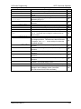
CONTENTS
SECTION 1 OVERVIEW ................................................................1-1
1.1
1.2
1.3
Introduction ...................................................................................................... 1-1
IEEE 488.2 GPIB and RS232 Options............................................................. 1-1
Ethernet Option................................................................................................ 1-1
SECTION 2 IEEE 488.2 GPIB/RS232 FEATURES, FUNCTIONS
AND
SPECIFICATIONS......................................................2-1
2.1
2.2
2.3
2.4
2.5
Introduction ...................................................................................................... 2-1
Features........................................................................................................... 2-1
Programmable Functions................................................................................. 2-1
Readback Functions ........................................................................................ 2-2
Specifications................................................................................................... 2-2
2.5.1 Programming Resolution ..................................................................... 2-2
2.5.2 Programming Accuracy ....................................................................... 2-2
2.5.3 Readback Resolution .......................................................................... 2-2
2.5.4 Readback Accuracy............................................................................. 2-2
SECTION 3 IEEE 488.2 GPIB/ RS232 CONFIGURATIONS AND
REMOTE PROGRAMMING .........................................3-1
3.1
3.2
3.3
Rear Panel....................................................................................................... 3-1
3.4
Remote Programming Via RS232 ................................................................... 3-9
RS232 Setup Procedure.................................................................................. 3-3
GPIB/IEEE 488.2 Setup Procedure ................................................................. 3-4
3.3.1 Configuration Switch............................................................................ 3-5
3.3.2 Remote/Local Selection....................................................................... 3-6
3.3.3 Power-On GPIB Service Request (PON SRQ) Selection.................... 3-8
3.3.4 Shield Ground...................................................................................... 3-8
3.3.5 Address Selection................................................................................ 3-8
M550129-03 Rev G
vii
Contents
SG Series Programming
SECTION 4 ETHERNET INTERFACE FEATURES, FUNCTIONS AND
SPECIFICATIONS ..................................................... 4-1
4.1
Introduction ......................................................................................................4-1
4.1.1 Minimum System Requirements ..........................................................4-1
4.2
Features and Functions ...................................................................................4-2
4.2.1 Features...............................................................................................4-2
4.2.2 Programmable Functions.....................................................................4-3
4.2.3 Readback Functions ............................................................................4-3
4.3
Specifications ...................................................................................................4-3
4.3.1 Ethernet/LAN Configuration .................................................................4-3
4.3.2 Ethernet Configuration Factory Defaults..............................................4-4
4.3.3 Programming Resolution .....................................................................4-4
4.3.4 Programming Accuracy........................................................................4-4
4.3.5 Readback Resolution...........................................................................4-5
4.3.6 Readback Accuracy .............................................................................4-5
SECTION 5 ETHERNET CONFIGURATION
AND REMOTE
PROGRAMMING ....................................................... 5-1
5.1
5.2
5.3
viii
Rear Panel .......................................................................................................5-1
Ethernet Setup Procedure................................................................................5-3
5.2.1 Network Setup Using DHCP ................................................................5-4
5.2.2 Network Setup Using Auto-IP ..............................................................5-5
5.2.3 Network Setup Using the Serial COM Port ..........................................5-6
5.2.4 Network Setup Using Web Browser.....................................................5-7
5.2.5 Configuration Switch ............................................................................5-8
5.2.6 Remote/Local Selection .......................................................................5-9
External User Control Signal Connector ........................................................5-10
5.4
Programming/Communication Via Ethernet...................................................5-13
5.4.1 Raw Socket Interface.........................................................................5-13
5.4.2 VXI-11 Protocol..................................................................................5-13
5.4.3 Web Server ........................................................................................5-13
5.5
Ethernet Web Pages, Overview .....................................................................5-14
5.5.1 HOME ................................................................................................5-16
5.5.2 IP CONFIGURATION.........................................................................5-17
5.5.3 SETTINGS .........................................................................................5-21
5.5.4 STATUS.............................................................................................5-24
5.5.5 POWER .............................................................................................5-26
5.5.6 PRESETS ..........................................................................................5-28
5.5.7 SECURITY.........................................................................................5-30
M550129-03 Rev G
SG Series Programming
Contents
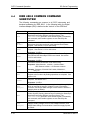
SECTION 6 IEEE 488.2 GPIB/RS232/ETHERNET AND SCPI
COMMAND OPERATION ...........................................6-1
6.1
6.2
Introduction ...................................................................................................... 6-1
6.3
Ethernet LXI™, VXI-11, and SCPI Conformance Information ......................... 6-8
6.3.1 Parameter Definitions .......................................................................... 6-8
6.3.2 Units .................................................................................................... 6-9
6.3.3 Conventions......................................................................................... 6-9
6.3.4 Queries ................................................................................................ 6-9
6.4
6.5
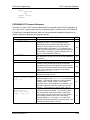
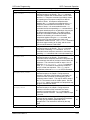
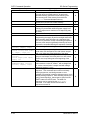
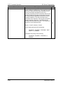
IEEE 488.2 Common Command Subsystem................................................. 6-10
6.6
MEASURE SCPI Command Subsystem ....................................................... 6-17
6.6.1 MEASURE SCPI Command Summary.............................................. 6-17
6.6.2 MEASURE SCPI Command Reference ............................................ 6-17
6.7
OUTPUT SCPI Command Subsystem .......................................................... 6-18
6.7.1 OUTPUT SCPI Command Summary................................................. 6-18
6.7.2 OUTPUT SCPI Command Reference ............................................... 6-18
6.8
STATUS SCPI Command Subsystem ........................................................... 6-19
6.8.1 STATUS SCPI Command Summary ................................................. 6-19
6.8.2 STATUS SCPI Command Reference ................................................ 6-20
6.9
SYSTEM SCPI Command Subsystem .......................................................... 6-21
6.9.1 SYSTEM SCPI Command Summary................................................. 6-21
6.9.2 SYSTEM SCPI Command Reference ............................................... 6-22
Register Definitions.......................................................................................... 6-1
6.2.1 SCPI Status Byte................................................................................. 6-1
6.2.2 Standard Event Status Register (ESR) ............................................... 6-3
6.2.3 Protection Condition and Protection Event Status Register ................ 6-3
6.2.4 Operation Status and Questionable Status Registers ......................... 6-5
6.2.5 Error/Event Queue............................................................................... 6-5
6.2.6 Serial Poll Operation............................................................................ 6-8
SOURCE SCPI Command Subsystem.......................................................... 6-12
6.5.1 SOURCE SCPI Command Summary ................................................ 6-12
6.5.2 SOURCE SCPI Command Reference............................................... 6-13
6.5.3 RAMP FUNCTION............................................................................. 6-16
6.10 HTRIGGER SCPI Command Subsystem ...................................................... 6-25
6.10.1
6.10.2
HTRIGGER SCPI Command Summary........................................... 6-25
HTRIGGER SCPI Command Reference ......................................... 6-25
6.11 TRIGGER SCPI Command Subsystem......................................................... 6-26
6.11.1
6.11.2
TRIGGER SCPI Command Summary ............................................. 6-26
TRIGGER SCPI Command Reference ............................................ 6-26
6.12 CALIBRATION SCPI Command Subsystem ................................................. 6-27
6.12.1
M550129-03 Rev G
CALIBRATION SCPI Command Summary...................................... 6-27
ix
Contents
SG Series Programming
6.12.2
CALIBRATION SCPI Command Reference.....................................6-29
6.13 SGI-Unique Commands .................................................................................6-32
6.13.1
6.13.2
6.13.3
6.13.4
6.13.5
Restrictions on Sequence Programming:.........................................6-32
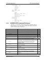
SGI SOURCE SCPI Command Subsystem .....................................6-33
SGI PROGRAM SCPI Command Subsystem..................................6-34
SGI MEASURE SCPI Command Subsystem...................................6-41
SGI HTRIGGER SCPI Command Subsystem .................................6-41
6.14 Examples of Using the SCPI Commands ......................................................6-42
6.14.1
6.14.2
6.14.3
6.14.4
6.14.5
6.14.6
6.14.7
6.14.8
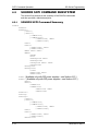
6.14.9
VI Mode Example.............................................................................6-42
OVP Setup Example ........................................................................6-42
Trigger Example...............................................................................6-43
Hardware Trigger Example ..............................................................6-44
Ramp V Example .............................................................................6-44
Ramp I Example...............................................................................6-44
Ramp V Example 2 ..........................................................................6-45
Power On INIT Example ..................................................................6-45
Sequence Creation and Execution Examples ..................................6-46
SECTION 7 CALIBRATION .......................................................... 7-1
7.1
7.2
7.3
7.4
Introduction ......................................................................................................7-1
7.5
7.6
7.7
Overvoltage Protection Programming Calibration (Ethernet, GPIB) ................7-6
7.8
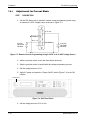
ANALOG PROGRAM ADJUSTMENT............................................................7-11
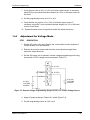
7.8.1 Adjustment for Current Mode.............................................................7-14
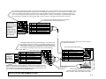
7.8.2 Adjustment for Voltage Mode.............................................................7-15
Setup for Calibration ........................................................................................7-2
Voltage Programming Calibration (Ethernet) ...................................................7-3
Voltage Program Gain/Offset and Measurement Readback Calibration (Ethernet,
GPIB) 7-5
Current Programming Calibration (Ethernet) ...................................................7-7
Current Programing gain/offset and Measurement Readback Calibration
(Ethernet, GPIB)...............................................................................................7-9
SECTION 8 SCPI STATUS IMPLEMENTATION............................ 8-1
List of Tables
Table 3-1. Remote/Local Switch .................................................................................. 3-6
Table 3-2. Remote Power-on Conditions..................................................................... 3-7
Table 5-1. Remote/Local Switch ................................................................................. 5-9
Table 5-2. Remote Mode Power-on Conditions........................................................ 5-10
Table 5-3. External User Control Signal Connector Pinout – Ethernet only ............. 5-11
x
M550129-03 Rev G
SG Series Programming
Contents
Table 6-1. SCPI Status Byte........................................................................................6-2
Table 6-2. Standard Event Status Register .................................................................6-3
Table 6-3. Protection Condition and Event Status Registers ......................................6-4
Table 6-4. SCPI Error Codes.......................................................................................6-5
Table 6-5. System Fault Registers ............................................................................6-24
List of Figures
Figure 3-1. SG Unit with GPIB/RS232 option..............................................................3-1
Figure 3-3. SG Unit with RS232 only...........................................................................3-2
Figure 3-5. SGA Configuration Switch for GPIB..........................................................3-5
Figure 3-6. SGI 8-pin Configuration Switch for GPIB or Ethernet ...............................3-5
Figure 3-7. SGI 4-pin Configuration Switch for Ethernet .............................................3-5
Figure 5-1. SG Rear Panel with Ethernet/RS232 Options...........................................5-1
Figure 5-2. SG Rear Panel with Ethernet/RS232 Options...........................................5-2
Figure 5-3. SGI Rear Panel with Ethernet/RS232 Options (4-pin Config Switch shown) 5-3
Figure 5-4. Power Supply’s Home Page (SGI shown here) ...........................................5-5
Figure 5-5. SG 8-pin Configuration Switch for the Ethernet Option.............................5-8
Figure 5-6. SG 4-pin Configuration Switch for the Ethernet Option.............................5-8
Figure 5-7. External User Connector (rear panel view) Designation (10-pin Molex) .5-11
Figure 5-9. SGI Banner and Tabs .............................................................................5-14
Figure 5-15. Alert Message for Save Settings...........................................................5-23
Figure 5-16. Status Page...........................................................................................5-24
Figure 5-20. Add New User Window from Security Page..........................................5-31
Figure 5-21. Edit Existing User Window from Security Page ....................................5-32
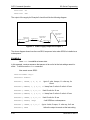
Figure 6-1. Power Supply Output for Example 1 .......................................................6-47
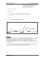
Figure 6-3. Power Supply Output for Example 2 .......................................................6-48
Figure 6-5. Power Supply Output for Example 3 .......................................................6-50
Figure 6-7. End-of-Sequence Pause for Example 4..................................................6-51
Figure 6-9. Power Supply Output for Example 5 .......................................................6-55
Figure 6-11. Power Supply Output for Example 6 .....................................................6-56
Figure 6-13. Power Supply Output for Example 7 .....................................................6-59
Figure 7-1. Potentiometer Locations ..........................................................................7-12
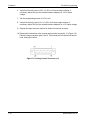
Figure 7-2. Precision Current Shunt ...........................................................................7-13
Figure 7-3. Remote Current Programming Using 0-5 VDC or 0-10 VDC Voltage Source
....................................................................................................................................7-14
Figure 7-4. SGI Front Panel .......................................................................................7-14
Figure 7-5. Remote Voltage Programming Using 0-5 VDC or 0-10 VDC Voltage Source
....................................................................................................................................7-15
Figure 7-6. Analog Control Connector (J1).................................................................7-16
M550129-03 Rev G
xi
Contents
SG Series Programming
This page intentionally left blank.
xii
M550129-03 Rev G
SECTION 1
OVERVIEW
1.1
INTRODUCTION
This manual provides instructions for full remote programming control and
monitoring from a computer, for your SG series high power DC power supply.
For easy navigation to the applicable instructions, this manual separates
GPIB and RS232 setup instructions from Ethernet setup instructions. The
instructions then converge where they are common to all three interface
options. See Sections 1.2 and 1.3 for orientation. Use this programming
manual in conjunction with your SGA or SGI Operation manual.
1.2
IEEE 488.2 GPIB AND RS232 OPTIONS
If you are using the IEEE 488.2 GPIB or RS232 interface, go to:
• Section 2 for features, functions and specifications,
• Section 3 for configuration and remote programming setup
• Section 6 for SCPI commands and definitions
• Section 7 for calibration procedures
• Section 8 for SCPI Status Implementation
1.3
ETHERNET OPTION
If you are using an Ethernet interface, go to:
• Section 4 for features, functions, and specifications
• Section 5 for configuration and for programming setup of your SG power
supply via the Ethernet
• Section 6 for SCPI commands and definitions
• Section 7 for calibration procedures
• Section 8 for SCPI Status Implementation
M550129-03 Rev G
1-1
Overview
SG Series Programming
This page intentionally left blank.
1-2
M550129-03 Rev G
SECTION 2
IEEE 488.2 GPIB/RS232
FEATURES, FUNCTIONS
AND SPECIFICATIONS
2.1
INTRODUCTION
This section introduces the features, functions and specifications for IEEE 488.2
GPIB and RS232.
2.2
FEATURES
•
•
•
•
•
•
•
•
•
2.3
16-bit programming and 16-bit readback of voltage and current
Programmable overvoltage protection with reset
IEEE 488.2 and SCPI compliant command set
User selectable Constant-Voltage/Constant-Current or Foldback mode,
with reset
Voltage Ramp and Current Ramp functions
Field-upgradable firmware via RS232
Soft calibration
Rear panel IEEE 488.2 and RS232 control interface
Rear panel configuration switch
PROGRAMMABLE FUNCTIONS
•
•
•
•
•
•
•
Output voltage and current
Soft limits for voltage and current
Overvoltage protection
Output enable/disable
Maskable fault interrupt
Hold and trigger
Full calibration
M550129-03 Rev G
2-1
IEEE/GPIB Features, Functions, Specifications
2.4
SG Series Programming
READBACK FUNCTIONS
• Actual measured voltage and current
• Voltage and current settings
• Soft voltage and current limits
• Overvoltage protection setting
• Status and Accumulated Status registers
• Programming error codes
• Fault codes
• Manufacturer, power supply model, and firmware version identification
2.5
SPECIFICATIONS
Specifications are subject to change without notice. Refer to your SGA or SGI
power supply operation manual for effects of line regulation, load regulation,
and temperature on accuracy specifications.
2.5.1
Programming Resolution
Voltage: 0.002% of full scale
Current: 0.002% of full scale
Overvoltage Protection: 0.002% of full scale (full scale is 110% of max
output voltage.)
2.5.2
Programming Accuracy
Voltage: ± ( 0.1% of maximum output voltage)
Current: ± ( 0.4% of maximum output current)*
Overvoltage Protection: ± (1.0% of max output voltage)
* After 30 minutes operation with fixed line, load, and temperature.
2.5.3
Readback Resolution
Voltage:
Current:
2.5.4
± 0.002% of full scale
± 0.002% of full scale
Readback Accuracy
Voltage: ± ( 0.15% of full scale output voltage)
Current: ± ( 0.4% of full scale output current)*
* After 30 minutes operation with fixed line, load, and temperature.
2-2
M550129-03 Rev G
SECTION 3
IEEE 488.2 GPIB/ RS232
CONFIGURATIONS
AND REMOTE PROGRAMMING
3.1
REAR PANEL
This section provides illustrations of the SG power supply’s rear panel
layout, which differs among the SG models. Figure 3-1, Figure 3-2 and
Figure 3-3 are examples. Regardless of the layout, the component
functions are common across all models, and those that are pertinent to
the RS232 and IEEE 488.2 GPIB options are described here.
Figure 3-1. SG Unit with GPIB/RS232 Option
1 – RS232 (RJ-11) connector
2 – Configuration Switch (may be 8-pin or 4-pin) - for correct settings see
Section 3.3.1.
3 – IEEE 488.2 GPIB connector
M550129-03 Rev G
3-1
IEEE/RS232 Configuration and Remote Programming
SG Series Programming
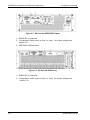
Figure 3-2. SG Unit with GPIB/RS232 Option
1 – RS232 (RJ-11) connector
2 – Configuration Switch (may be 8-pin or 4-pin) - for correct settings see
Section 3.3.1
3 – IEEE 488.2 GPIB connector
Figure 3-3. SG Unit with RS232 only
1 – RS232 (RJ-11) connector
2 – Configuration Switch (may be 8-pin or 4-pin). For correct settings see
Section 3.3.1
3-2
M550129-03 Rev G
SG Series Programming
3.2
IEEE/RS232 Configuration and Remote Programming
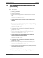
RS232 SETUP PROCEDURE
This procedure is a quick reference for the configuration requirements for
RS232. Refer to Section 3.3.1 for detailed information on the rear panel
configuration switches.
1. Build an RS232 comm cable per the following pinout description,
which is illustrated in Figure 3-4:
RJ-11 Pin to DB-9 Socket
1
to
2
2
to
7
3
NC
4
to
5
5
to
3
6
to
8
Figure 3-4. RS232 Comm Cable Wiring
2. Set the rear panel Remote/Local switch to Remote (On or 1).
3. Connect power to the unit and turn on the unit.
4. SGA: skip this step and go to the next step.
SGI: From the Home menu page 3, press (F1) to enter the Remote
menu. Using the up-down arrows of the NAVPAD (see SGI Operation
Manual) change the baud rate for RS232 to 19200.
5. Use one of the available programs for serial communication, such as
MS HyperTerminalTM, and set the RS232 baud rate to 19200, 8 data
bits, no parity, 1 stop bit, and no flow control.
If you choose to use MS HyperTerminalTM:
a. After inputting the above parameters, in the HyperTerminalTM
window click the disconnect icon and then the properties icon.
b. In the properties window select the Settings tab.
c. In the Settings window click the ASCII Setup button.
d. In the ASCII Setup window in the ASCII Sending section, check
“Echo typed characters locally” and in the ASCII Receiving
section, check “Append line feeds to incoming line ends.” Leave
all other check boxes in their default state.
M550129-03 Rev G
3-3
IEEE/RS232 Configuration and Remote Programming
SG Series Programming
6. Establish communication.
7. Test the communication interface by issuing the *IDN? Command.
This returns the supply’s model and serial numbers, and software
version(s), as well as the last calibration date, and does not affect the
output of the supply. (If using SGI, navigate to the INFO page of the
SGI unit’s front panel display to verify).
3.3
IEEE 488.2 GPIB SETUP PROCEDURE
1. Set the rear panel Local/Remote switch to Remote (On or 1).
2. SGA: select the GPIB address using the rear panel DIP switches.
SGI: set the GPIB address via the front panel menu (Refer to SGI
Operation manual).
3. Connect GPIB cable from the controlling computer to the power
supply.
NOTE: If operating in an inherently noisy environment, e.g., high RF
or other radiated emissions, a double-shielded GPIB cable is
recommended.
4. Connect power to the unit and turn on the unit.
5. Using a GPIB communication software, test the communication
interface by issuing the *IDN? Command. This returns the supply’s
model and serial numbers, and software version(s), as well as the last
calibration date, and does not affect the output of the supply. (If using
SGI, navigate to the INFO page of the SGI unit’s front panel display to
verify).
3-4
M550129-03 Rev G
SG Series Programming
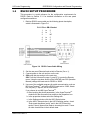
3.3.1
IEEE/RS232 Configuration and Remote Programming
Configuration Switch
The DIP switch (may be 8-pin or 4-pin) is accessible from the rear panel to
configure the supply for your particular system and application. The following
figures show the configuration, as set up in Section 3.2, and with GPIB
address set to five (5) for the SGA. In the SGI only Remote/Local position is
used, addressing is done through the front panel menu (See SGI operation
manual).
Note: There is one of two types of DIP switches: toggle or rocker.
For toggle switches, the shading indicates the position of the toggle switch.
For rocker switches, the shading indicates the depressed side.
Figure 3-5. SGA Configuration Switch for GPIB
Figure 3-6. SGI 8-pin Configuration Switch for GPIB or Ethernet
Figure 3-7. SGI 4-pin Configuration Switch for Ethernet
M550129-03 Rev G
3-5
IEEE/RS232 Configuration and Remote Programming
3.3.2
SG Series Programming
Remote/Local Selection
Set the rear panel Remote/Local switch to select remote or local operation.
Remote ON switch (rocker) is top depressed.
Table 3-1. Remote/Local Switch
Switch
Position
ON
OFF
Description
Remote operation selected. *
Local operation selected, and front panel control is enabled.
NOTE: Unit will switch to remote operation upon issuing the
first GPIB or RS232 non-query command.
* In the ON position, the power hardware and GPIB card initialize
to the remote state at power-on.
When in remote operation, the front panel control remains
disabled regardless of the state of the GPIB interface REN
(Remote ENable) line or the GTL (Go To Local) command.
To revert to front panel control, use the special command
SYST:LOCAL <on/off>.
Powering up in remote mode will result in the operating conditions described
in Table 3-2.
3-6
M550129-03 Rev G
SG Series Programming
IEEE/RS232 Configuration and Remote Programming
Table 3-2. Remote Power-on Conditions
Condition
Voltage
Current
Default
0 Volts (initial from factory power-on voltage); otherwise,
last value saved by SCPI command.
See CAL:INIT:VOLT
0 Amps (initial from factory power-on current); otherwise,
last value saved by SCPI command.
See CAL:INIT:CURR
Soft Voltage Limit
Model maximum voltage *
Soft Current Limit
Model maximum current *
OVP Trip Voltage
Model maximum voltage +10% (initial from factory poweron OVP); otherwise, last value saved by SCPI command.
See CAL:INIT:VOLT:PROT
Delay
0.5 seconds
Foldback Protection
OFF (non-configurable)
Output
ON ** See CAL:MOD:POWERON
Hold
OFF
Unmask
NONE
Service Request
Capability
OFF
* User-programmable temporary limit (reverts to power-on defaults after power
cycle or Reset command is issued).
** User-selectable.
M550129-03 Rev G
3-7
IEEE/RS232 Configuration and Remote Programming
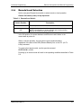
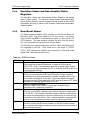
3.3.3
SG Series Programming
Power-On GPIB Service Request (PON SRQ) Selection
Set the rear panel PON SRQ switch to ON to cause a GPIB service request
to be sent to the computer controller when the supply is turned on.
POWER-ON GPIB SERVICE REQUEST (PON SRQ) SWITCH
Switch Position
Description
ON
Power-On SRQ selected
OFF
No Power-On SRQ selected
Refer to your specific GPIB controller card manual for further details on serial
polling.
3.3.4
Shield Ground
Connects GPIB cable shield to chassis ground.
3.3.5
Address Selection
The address selection for a unit is the GPIB address of that device (1-30).
SCPI reserves channel 0 as the global channel to address all channels.
The SGA address selection is binary with switch A0 as the LSB, and with
switch A4 as the MSB. The rear panel switch illustration in Section 3.3.1
shows the address selection 00101 in binary (5 decimal).
The SGI address is selected and enabled from a list in the Remote menu.
See SGI Operation manual for more details on Remote menu, Navigation and
Editing.
ADDRESS SWITCHES
3-8
Switch Position
Description
ON
1
OFF
0
M550129-03 Rev G
SG Series Programming
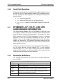
3.4
IEEE/RS232 Configuration and Remote Programming
REMOTE PROGRAMMING VIA RS232
The RS232 interface operates at fixed 19.2K baud for SGA and is
selectable from 2400 to 19.2K baud for the SGI, with 8 data bits, no parity,
and 1 stop bit.
All commands are supported at the RS232 interface with the exception of
the Service Request (SRQ) function, which is a GPIB-specific function
requiring the dedicated Service Request line of the IEEE 488.2 interface. In
this case, the SRQ function has no effect. The RS232 interface is
accessible through the rear panel 6-pin RJ-11 connector (Figure 3-8),
labeled RS232 on the power supply’s rear panel (see Figure 3-1, Figure 3-2
and Figure 3-3).
Figure 3-8. RS232 Rear Panel RJ-11 Connector Pinout
M550129-03 Rev G
3-9
IEEE/RS232 Configuration and Remote Programming
SG Series Programming
This page intentionally left blank.
3-10
M550129-03 Rev G
SECTION 4
ETHERNET INTERFACE
FEATURES, FUNCTIONS AND
SPECIFICATIONS
4.1
INTRODUCTION
This section covers the Remote Programming Ethernet Interface Option for
the SG series power supplies. This optional configuration enables you to
operate your Sorensen power supply from a computer via Ethernet IEEE802.3 or RS232 communication protocols, or with SCPI-compatible language,
allowing full remote programming control and monitoring of your power
supply.
An important point is that this Ethernet option is
™ (LAN eXtensions for
Instrumentation) class C compliant. LXI™ is an instrumentation platform
based on industry-standard Ethernet technology designed to provide ease of
integration by modularity, flexibility and performance.
4.1.1
Minimum System Requirements
The minimum software and equipment requirements to operate your
Sorensen Ethernet product depend on whether it is connected directly to your
PC or connected to the Internet or to a Local Area Network (LAN).
PC CONNECTION
To operate your Sorensen product with Ethernet option connected directly to
a PC (no Internet or LAN connection), you will need:
• Pentium-based laptop or desktop computer running Microsoft Windows
XP (or better)
• Ethernet based Network Interface Card (NIC) or built-in port capable of
10/100 MBit operation
• CAT 5 cable Ethernet crossover cable
• Microsoft Internet Explorer version 6.0 or later
• Sun Microsystems Java Runtime Environment
M550129-03 Rev G
4-1
Ethernet Features, Functions and Specifications
SG Series Programming
INTERNET OR LAN CONNECTION
To operate your Sorensen Ethernet product connected to the Internet or a
LAN you will need:
• Pentium-based laptop or desktop computer running Microsoft Windows
XP (or better)
• Ethernet based Network Interface Card (NIC) or built-in port capable of
10/100 MBit operation
• Appropriate Ethernet modem for Internet connection, or
• Switch or hub (Linksys brand strongly recommended) for LAN
connection
• Standard CAT 5 Ethernet interconnect cable
• Microsoft Internet Explorer version 6.0 or later
• Sun Microsystems Java Runtime Environment
4.2
FEATURES AND FUNCTIONS
4.2.1
Features
• Ethernet/LAN connectivity, 10/100base-T compatible
• Fully
™ (LAN eXtensions for Instrumentation) class C compliant
• Built-in Web Server for direct control using Internet Explorer 6.0 or
higher
• 16-bit programming and 16-bit readback of voltage and current
• Programmable overvoltage protection with reset
• SCPI compliant command set
• User-programmable signals including Local/Remote Sense relay drive,
External Polarity relay drive, and Disconnect (Isolate) Relay Drive
• User selectable Constant-Voltage/Constant-Current or Foldback mode,
with reset
• Voltage Ramp and Current Ramp functions
• Field-upgradeable firmware via RS232
• Full calibration through software control
• Rear panel Ethernet/IEEE-802.3 and RS232 control interface
• Rear panel External User Control Signal Interface
(Includes optically isolated external hardware trigger input)
• Rear panel configuration switch
4-2
M550129-03 Rev G
SG Series Programming
4.2.2
Ethernet Features, Functions and Specifications
Programmable Functions
• Output voltage and current
• Soft limits for voltage and current
• Overvoltage protection
• Output enable/disable
• Maskable fault interrupt
• Hold and trigger
• External relay control
• Full calibration
4.2.3
Readback Functions
• Measured voltage and current
• Voltage and current settings
• Soft voltage and current limits
• Overvoltage protection setting
• Status and Accumulated Status registers
• Programming error codes
• Fault codes
• Manufacturer, power supply model, and firmware version identification
4.3
SPECIFICATIONS
(SUBJECT TO CHANGE WITHOUT NOTICE)
4.3.1
Ethernet/LAN Configuration
• Ethernet:
IEEE-802.3 compliant
• Medium:
10/100 base-T
• Connection Monitoring:
• Protocol:
Media Sense supported
TCP/IP, IPV4
• ICMP (ping server):
Enable (default)/Disable
• IP Address Assignment: Automatic via DHCP (Primary default), Static,
or Automatic Private IP Addressing (Auto-IP, Secondary default)
• VXI-11 Discovery: Supported
• Security:
each user
M550129-03 Rev G
Password protected access, and selective permissions for
4-3
Ethernet Features, Functions and Specifications
4.3.2
SG Series Programming
Ethernet Configuration Factory Defaults
PARAMETER
Host Name
Description
IP Address
IP Addressing mode
Subnet Mask
Gateway
DNS Server
Listening Port
User ID
Password
Ping Echo
DEFAULT
SGx<base model>-<last four digits of serial number>
Sorensen Power Supply SGx<base model>
DHCP-acquired (Primary default*) If DHCP absent,
assigned via Auto-IP (Secondary default*)
DHCP-acquired (Primary default*)
DHCP-acquired (Primary default*) If DHCP absent,
assigned via Auto-IP (Secondary default*)
0.0.0.0
0.0.0.0
9221
admin
password
On
* Primary/Secondary defaults:
The Ethernet interface provides the opportunity to set both a Primary and
a Secondary IP configuration in the IP Configuration page (Section 5.5.2).
If the Primary fails, the system defaults to the Secondary configuration.
However, both setting “DHCP-acquired” and selecting “Auto IP Enabled”
together in the Primary configuration, prevents the power supply from
trying the Secondary configuration. Please see “TCP/IP Configuration”
and “Auto IP Enabled” under IP Configuration, Section 5.5.2 for more
detail.
4.3.3
Programming Resolution
SGA
4.3.4
Voltage
Current
0.002% of full scale
0.002% of full scale
Overvoltage
Protection
0.002% of full scale (full scale is 110% of
max output voltage.)
0.002% of full scale
0.002% of full scale
0.002% of full scale (full
scale is 110% of max
output voltage.)
Programming Accuracy
SGA
4-4
SGI
SGI
Voltage
± (0.1% of maximum output voltage)
± (0.1% + 0.1% of full scale)
Current
± (0.25% of full scale output current
Overvoltage
Protection
± (0.5% of max output voltage)
± (0.1% + 0.4% of full scale)
± (0.5% + 0.5% of full scale)
(full scale 110% of max. output
voltage)
M550129-03 Rev G
SG Series Programming
4.3.5
Readback Resolution
Voltage
Current
4.3.6
Ethernet Features, Functions and Specifications
SGA
0.002% of full scale
0.002% of full scale
SGI
0.02% of full scale
0.02% of full scale
Readback Accuracy
SGA
Voltage
± (0.1% of full scale output voltage)
Current*
± (0.25% of full scale output current)*
SGI
± (0.1% + 0.15% of
maximum output voltage)
± (0.1% + 0.4% of
maximum output current)
* After 30 minutes operation with fixed line, load, and temperature.
Note: Refer to the applicable power supply manual (SGA or SGI) for effects
of line regulation, load regulation, and temperature on accuracy
specifications.
M550129-03 Rev G
4-5
Ethernet Features, Functions and Specifications
SG Series Programming
This page intentionally left blank.
4-6
M550129-03 Rev G
SECTION 5
ETHERNET CONFIGURATION
AND REMOTE PROGRAMMING
5.1
REAR PANEL
This section provides illustrations of the SG power supply’s rear panel layout,
which differs among the SG models. Figure 5-1, Figure 5-2 and Figure 5-3
are examples. Regardless of the layout, the component functions are
common across all models, and those that are pertinent to the Ethernet
option are described here.
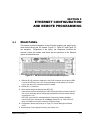
Figure 5-1. SG Rear Panel with Ethernet/RS232 Options
1 – Ethernet (RJ-45) connector. Adjacent to the RJ-45 connector are two green LEDs.
If one of the LEDs is lit, the link is connected either to a hub switch or to another
host. If both are lit, the connection speed is 100MB.
2 – RS232 (RJ-11) connector.
3 – Reset switch and green dual-purpose NET LED.
Reset switch (must be depressed until NET LED begins blinking, which could take
five or more seconds) returns configuration parameters to factory default settings
(see Section 4.3.2).
NET LED: when solid-lit, indicates Network Connectivity; blinking indicates
Instrument ID (See “Instrument ID” in Settings, Section 5.5.3). If the LED is off,
there is no Ethernet connection found by the power supply.
4 – Configuration Switch (may be 8-pin or 4-pin). For correct settings see Section
5.2.5)
5 –External User Control Signal Connector (see Section 5.3)
M550129-03 Rev G
5-1
Ethernet Configuration and Remote Programming
SG Series Programming
Figure 5-2. SG Rear Panel with Ethernet/RS232 Options
1 – Ethernet (RJ-45) connector. Adjacent to the RJ-45 connector are two green LEDs.
If one of the LEDs is lit, the link is connected either to a hub switch or to another
host. If both are lit, the connection speed is 100MB.
2 – RS232 (RJ-11) connector.
3 – Reset switch and green dual-purpose NET LED.
Reset switch (must be depressed until NET LED begins blinking, which could take
five or more seconds) returns configuration parameters to factory default settings
(see Section 4.3.2).
NET LED: when solid-lit, indicates Network Connectivity; blinking indicates
Instrument ID (See “Instrument ID” in Settings, Section 5.5.3). If the LED is off,
there is no Ethernet connection found by the power supply.
4 – Configuration Switch (may be 8-pin or 4-pin). For correct settings see Section
5.2.5)
5 –External User Control Signal Connector (see Section 5.3)
5-2
M550129-03 Rev G
SG Series Programming
Ethernet Configuration and Remote Programming
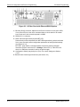
Figure 5-3. SGI Rear Panel with Ethernet/RS232 Options (4-pin Config Switch shown)
1 – Ethernet (RJ-45) connector. Adjacent to the RJ-45 connector are two green LEDs.
If one of the LEDs is lit, the link is connected either to a hub switch or to another
host. If both are lit, the connection speed is 100MB.
2 – RS232 (RJ-11) connector.
3 – Reset switch and green dual-purpose NET LED.
Reset switch (must be depressed until NET LED begins blinking, which could take
five or more seconds) returns configuration parameters to factory default settings
(see Section 4.3.2).
NET LED: when solid-lit, indicates Network Connectivity; blinking indicates
Instrument ID (See “Instrument ID” in Settings, Section 5.5.3). If the LED is off,
there is no Ethernet connection found by the power supply.
4 – Configuration Switch (may be 8-pin or 4-pin). For correct settings see Section
5.2.5)
5 –External User Control Signal Connector (see Section 5.3)
5.2
ETHERNET SETUP PROCEDURE
The Ethernet option is installed into the supply at the factory. Use the Setup
Procedure that applies to your system and application to configure the
Ethernet.
There are four methods of setting the IP address of the unit, each of which is
described in the subsections that follow:
• Set an IP address through DHCP (Primary default).
• If DHCP is not available, the unit can assign itself an IP address in the
Auto-IP (dynamic link local addressing) range (Secondary default).
• Use the serial communications port to manually assign an IP address.
(IP address can be set via the front panel on SGI units.)
• Set the IP address through the Web page interface.
M550129-03 Rev G
5-3
Ethernet Configuration and Remote Programming
SG Series Programming
NOTE: The SG Ethernet Option has been designed and tested to be fully
compatible with Microsoft Internet Explorer 6.0. This is the only browser
supported by Elgar Electronics Corporation (EEC) in its Ethernet-based
products. Earlier versions of Explorer (or browsers by other companies) may
or may not work correctly, and as such, are not supported by EEC.
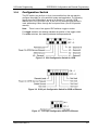
5.2.1
Network Setup Using DHCP
Before beginning this procedure, get access to the DHCP server or see your
network administrator to get the IP address assigned to the power supply.
NOTE: The power supply is VXI-11 compliant, so even without access to the
DHCP server, it is still possible to discover the IP address assigned to the
power supply with programs such as National Instrument’s NI-VISA.
1. Start with the power supply in the power-off state.
2. Connect a RJ-45 network cable from the power supply to the network
with the DHCP server.
3. Power on the power supply and allow the power supply to perform its
initialization.
4. Identify the IP address assigned to the power supply by accessing the
DHCP server, by any of three ways:
•
asking your network administrator
•
discovering it with a VXI-11 compliant discover program
•
connect using a computer serial communications program
such as HyperTerminalTM set for 19200 baud, no parity, 8 data
bits, 1 stop bit and request the IP address with the command,
SYST:NET:IP?<Enter>. You will receive a response that
includes two IP addresses in the form of four sets of octets
separated by a dot: e.g., 192.168.4.3 and 92.168.4.3 or 0.0.0.0
and 72.32.3.5
If you choose to use MS HyperTerminalTM to identify the IP
address:
a. After inputting the above parameters (baud rate, etc.),
in the HyperTerminalTM window click the disconnect
icon and then the properties icon.
b. In the properties window select the Settings tab.
c. In the Settings window click the ASCII Setup button.
d. In the ASCII Setup window in the ASCII Sending
section, check “Echo typed characters locally” and in
the ASCII Receiving section, check “Append line
feeds to incoming line ends.” Leave all other check
boxes in their default state.
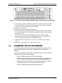
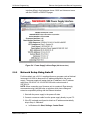
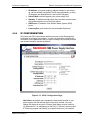
5. The SG Ethernet hardware is now configured. Open Internet Explorer
6 or higher, or compatible Web browser and enter the IP address of
the power supply to view the Home page of the power supply. Figure
5-4 shows the SGI Power Supply Home page; the SGA Power Supply
5-4
M550129-03 Rev G
SG Series Programming
Ethernet Configuration and Remote Programming
Interface differs in that its banner shows “SGA” and it does not come
with the POWER or PRESETS pages.
Figure 5-4. Power Supply’s Home Page (SGI shown here)
5.2.2
Network Setup Using Auto-IP
For this method, use a VXI-11 compliant discovery program such as National
Instrument’s NI-VISA to discover the IP address assigned to the power
supply. The power supply will assign itself an IP address in the IP address
range from 169.254.0.1 to 169.254.255.254 with a subnet mask of
255.255.0.0.
NOTE: When connecting your Sorensen unit to a network, Elgar strongly
recommends using Linksys® hubs or switches, which have undergone
extensive compatibility testing with the Ethernet interface.
1. Start with the power supply in the power-off state.
2. Connect a crossover cable from the power supply directly to your PC.
3. If the PC is already configured to obtain an IP address automatically,
skip to Step 4. Otherwise:
a. In Windows click Start, Settings, Control Panel.
M550129-03 Rev G
5-5
Ethernet Configuration and Remote Programming
SG Series Programming
b. Click open Network Connections. (For XP, if in the Category
View, click Network and Internet Connections, and then Network
Connections).
c. In the Network Connections window, right click the icon for
the network adapter used to connect to the power supply,
and click Properties.
d. Find the TCP/IP protocol item under the Configuration tab
(for XP: find the item under the General tab), and click
Properties. Select Obtain an IP Address Automatically.
e. Click OK to save the change.
f.
Click OK again to apply the settings to the network
adapter.
4. In Windows, click Start, and then Run…
5. In the Run window, type “ipconfig /release” and click OK.
6. Again click Start, and then Run…
7. In the Run window, type “ipconfig /renew” and click OK. Your PC will
assign itself an IP address in the Auto-IP range.
8. Power on the power supply and allow the power supply to perform its
initialization.
9. Identify the IP address assigned to the power supply by discovering it
with a
VXI-11 compliant discover program.
10. Continue by following the procedure in Section 5.2.4.
NOTE: When Auto-IP assigns an IP address, Web page connections will
time out after 5 minutes of inactivity, which requires logging in again.
5.2.3
Network Setup Using the Serial COM Port
1. Connect from the PC COM1 port to the power supply’s RS232 port
(see Figure 5-1 for port location) using a straight-through DB91 to RJ1 connector.
2. Have ready the IP address (e.g. 192.168.0.200) and subnet mask
(e.g., 255.255.255.0) to be assigned to the power supply.
3. Run a serial terminal program, such as MS HyperTerminalTM. Set the
baud rate (bits per second) to 19200, data bits to 8, parity to none,
stop bits to 1, flow control to none. Establish the connection.
If you choose to use MS HyperTerminalTM:
a. After inputting the above parameters, in the HyperTerminalTM
window click the disconnect icon and then the properties icon.
b. In the properties window select the Settings tab.
c. In the Settings window click the ASCII Setup button.
5-6
M550129-03 Rev G
SG Series Programming
Ethernet Configuration and Remote Programming
d. In the ASCII Setup window in the ASCII Sending section,
check “Echo typed characters locally” and in the ASCII
Receiving section, check “Append line feeds to incoming line
ends.” Leave all other check boxes in their default state.
4. Power on the power supply and allow the power supply to perform its
initialization. In HyperTerminalTM, tap the ENTER key a couple of times
to clear the input buffer
NOTE: tapping the ENTER key is also required to clear any errors
when using HyperTerminalTM, rather than tapping the BACKSPACE or
DELETE keys.
5. Set the IP address by typing SYST:NET:IP “xxx.xxx.xxx.xxx”
<enter> (where xxx.xxx.xxx.xxx is the new IP address). For example,
to set 192.168.0.200 as the IP address, type SYST:NET:IP
“192.168.0.200” <enter>
NOTE: the format requires a single space after SYST:NET:IP and
double quotes around the IP address numbers.
6. Set the subnet mask with SYST:NET:MASK xxx.xxx.xxx.xxx
<enter>.
7. After configuring all settings, verify with the queries, SYST:NET:IP?
<enter> and SYST:NET:MASK? <enter>.
8. Type *RST<enter> to perform a power–on reset of the power supply.
9. The SG Ethernet hardware is now configured. Open your Web
browser and enter the assigned IP address of the power supply to
view the power supply web page.
10. The power supply is now ready to be plugged into the network.
5.2.4
Network Setup Using Web Browser
Note: This requires that the PC’s IP address be in the same network as the
IP address assigned to the power supply. It also requires your Web browser
to open the power supply’s Home page.
Note: For proper functionality on the Web browser, ensure that Sun
Microsystems’ Java Runtime Environment is installed on the PC. Visit
www.java.com to download, after setting the Web browser’s Security to
enable scripting of Java applets:
1. In the Tools menu, select Internet Options… and click the Security
tab.
2. At the bottom of the Security window click Custom level…
3. In the Reset custom settings drop-down, select Medium and click
Reset and then OK).
4. Now use your Web browser for Network Setup:
In the Web browser’s Address: field, type xxx.xxx.x.xxx where
xxx.xxx.x.xxx is the power supply’s IP address. (See Section 5.4.3 for
description and operation information).
M550129-03 Rev G
5-7
Ethernet Configuration and Remote Programming
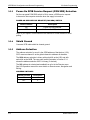
5.2.5
SG Series Programming
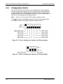
Configuration Switch
Use the DIP switch (will have either four or eight switches and is accessible
from the rear panel) to configure the power supply with the installed Ethernet
interface adapter. The following figures show the DIP switch configuration for
the Ethernet connection. On the Ethernet master, set the rear panel switch to
Remote On, and disregard all remaining switches.
Note: There is one of two types of DIP switches: toggle or rocker.
For toggle switches, the shading indicates the position of the toggle switch.
For rocker switches, the shading indicates the depressed side.
Figure 5-5. SG 8-pin Configuration Switch for the Ethernet Option
Figure 5-6. SG 4-pin Configuration Switch for the Ethernet Option
5-8
M550129-03 Rev G
SG Series Programming
5.2.6
Ethernet Configuration and Remote Programming
Remote/Local Selection
Set the rear panel Remote/Local switch to select remote or local operation.
Remote ON switch (rocker) is top depressed.
Table 5-1. Remote/Local Switch
Switch Position
Description
ON
Remote operation selected.*
OFF
Local operation selected, and front panel control is enabled.
NOTE: Unit will switch to remote operation upon issuing the first
Ethernet or RS232 non-query command.
* In the ON position, the power hardware and Ethernet card initialize to the
remote state at power-on.
When in remote operation, the front panel control remains disabled
regardless of the state of the REN (Remote ENable) line, or the GTL (Go To
Local) command.
To revert to front panel control, use the special command
SYST:LOCAL <on/off>.
Powering up in remote mode will result in the operating conditions described in Table
5-2.
M550129-03 Rev G
5-9
Ethernet Configuration and Remote Programming
SG Series Programming
Table 5-2. Remote Mode Power-on Conditions
Condition
Default
0 Volts (initial from factory power–on voltage); otherwise, last
value saved by SCPI command or by the SAVE SETTINGS
button in the Web Settings page.
See CAL:INIT:VOLT to change.
0 Amps (initial from factory power–on current); otherwise, last
value saved by SCPI command or by the SAVE SETTINGS
button in the Web Settings page.
See CAL:INIT:CURR to change.
Voltage
Current
Soft Voltage Limit
Model maximum voltage *
Soft Current Limit
Model maximum current *
OVP Trip Voltage
Model maximum voltage +10% (initial from factory power–on
OVP); otherwise, last value saved by SCPI command or by
the SAVE SETTINGS button in the Web Settings page.
See CAL:INIT:VOLT:PROT to change.
Delay
0.5 seconds
Foldback Protection
OFF (non-configurable)
Output
ON ** See CAL:MOD:POWERON
Hold
OFF
Unmask
NONE
Service Request Capability
OFF
*
User-programmable temporary limit (reverts to power-on defaults after power
cycle or Reset command is issued).
** User-selectable
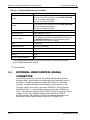
5.3
EXTERNAL USER CONTROL SIGNAL
CONNECTOR
A10-pin Molex connector (Figure 5-7) located at the rear panel provides
external auxiliary control signals to increase the user’s operating control of
the supply. The mating receptacle is Molex 43025-1000 with 10 female
terminals. The Molex terminals accommodate wire sizes from #20 - #24.
The relay outputs, when active, connect the POLARITY, ISOLATION and
SENSE pins (Pins 6, 7 and 8) of the connector to the relay COMMON pin
(Pin 5). The relays are rated at 120VAC/125VDC @ 1A. Any change in output
(voltage, current, etc.) initiated by the user from the RS232, GPIB, or
Ethernet interface, will generate a 10ms synchronization pulse at the rear
panel User Control Signal Connector of the unit (TRIGGER OUT).
5-10
M550129-03 Rev G
SG Series Programming
Ethernet Configuration and Remote Programming
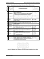
Designator
(Pin)
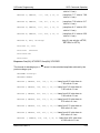
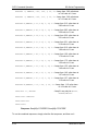
Table 5-3. External User Control Signal Connector Pinout – Ethernet only
Schematic
Symbol
Functional Description
Output signal, open collector, active-low. Asserted
when in foldback mode.
FOLDBACK
Emitter is on pin 9. (See OUTP:PROT:FOLD command
in the Output SCPI Command Subsystem, Section 6.7
of this manual).
Open anode (1k resistor on-board) input signal. Allows
SHUTDOWN the user to immediately shutdown the unit by presenting
a 10-20 mA input signal. Cathode on pin 9.
Output signal, open collector, active-low.
FAULT
Asserted when a fault is recorded in the fault register.
Emitter is on pin 9.
Synchronize output signal, open collector, active-low.
TRIGGER OUT Pulsed for 10 ms when a change in the output occurs.
Emitter is on pin 9.
For all relay contacts. Optionally connected to pin 9 by
COMMON
internal jumper
Output signal, relay contacts. Asserted (contacts close
POLARITY
to COMMON) when a negative voltage is programmed.
(e.g., SOURce:VOLTage -5.0)
Output signal, relay contacts. Asserted (contacts close
to COMMON) when the output relay is programmed
ISOLATION
OFF.
(e.g., OUTPut:ISOlation OFF)
Output signal, relay contacts. Asserted (contacts close
to COMMON) when the sense relay is programmed
SENSE
OFF.
(e.g., OUTput:SENse OFF)
1
2
3
4
5
6
7
8
9
Electrical
Characteristics
Max 60 VDC
Max 4 mA DC
Max 12 VDC
Max 6 VDC reverse
voltage
Max 60 VDC
Max 4 mA DC
Max 60 VDC
Max 7 mA DC
Max 2 ADC
Max 30 VDC
Max 60 W
Max 2 ADC
Max 30 VDC
Max 60 W
Max 2 ADC
Max 30 VDC
Max 60 W
ISO COMMON Opto-isolator common line.
10
TRIGGER IN
Hardware - Open Anode (1k resistor on-board) of optoisolator. Cathode on pin 9. This signal is provided for
external hardware triggering of sequence functions and
of voltage and current ramp functions.
Max 12 VDC
Max 6 VDC reverse
voltage
Figure 5-7. External User Connector (rear panel view) Designation (10-pin Molex)
M550129-03 Rev G
5-11
Ethernet Configuration and Remote Programming
SG Series Programming
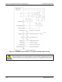
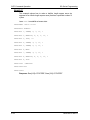
Figure 5-8. Example of Open Collector, TTL Input, and Relay Output Circuits
CAUTION
5-12
External relays must not be hot-switched; ensure that the voltage across the relay
contacts and the current through them is zero prior to changing the relay states.
M550129-03 Rev G
SG Series Programming
5.4
Ethernet Configuration and Remote Programming
PROGRAMMING/COMMUNICATION VIA
ETHERNET
With the Ethernet option, there are four basic methods to communicate with
the power supply from a PC:
•
•
•
•
5.4.1
raw socket interface, sending delimited strings (default delimiter is
<LineFeed>)
application program that utilizes VXI-11 Discovery protocol
Web browser (Internet Explorer 6 or higher or compatible) and the
internal Web server, with scripting of Java applets enabled
RS232C serial interface
Raw Socket Interface
The essential components of communicating via a raw socket interface are
the socket number, IP address and command delimiter. The default values
are: socket = 9221, IP address = 192.168.0.200 (when static IP is enabled),
and delimiter = line feed <LF>. All of these items may be changed via either
the Web browser (see IP CONFIGURATION, Section 5.5.2) or the RS232C
interface (see System SCPI command, Section 6.9).
For convenience and to comply with the proposed LXI™ standard, the VISA
resource name is available on the home page of the power supply’s Web
server.
5.4.2
VXI-11 Protocol
With programs such as National Instrument’s NI-VISA, the VXI-11 protocol
allows the power supply to be easily configured in a test system.
5.4.3
Web Server
To communicate with the power supply via the built-in Web server, open a
supported Web browser (Internet Explorer 6.0 or higher or compatible) and
type the IP address of the power supply in the “Address” field. Tap the ENTER
key to launch the power supply’s Ethernet Web page interface.
Note: To ensure proper functionality on your Web browser, Sun
Microsystems’ Java Runtime Environment must be installed on your PC. Visit
www.java.com to download. Also, set your Web browser’s Security to enable
scripting of Java applets. (In the Tools menu, select Internet Options… and
click the Security tab. At the bottom of the Security window click Custom
level…; in the Reset custom settings drop-down, select Medium and click
Reset and then OK).
M550129-03 Rev G
5-13
Ethernet Configuration and Remote Programming
5.5
SG Series Programming
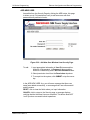
ETHERNET WEB PAGES, OVERVIEW
The layout of each of the Web pages includes the banner with the
heading, “Sorensen SGI (or SGA) Power Supply Interface” along with the
device name below and a LOGIN button to the right. Below the SGI
banner are eight tabs (six tabs in the SGA banner), each linked to its
corresponding page. On each page is a title line (title matches tab name).
In the title line is an area that frequently displays informational messages
(when warranted) as you use the Web interface, such as a confirmation
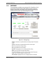
message or an error message.
Figure 5-9. SGI Banner and Tabs
Figure 5-10. SGA Banner and Tabs
Note: There are few differences between the SGA interface and the SGI
interface: their titles and device names in the banner, their specifics in the
Home page, and SGI has two pages that are not included in the SGA:
Power and Presets. Unless SGA and SGI interfaces are both shown, most
illustrations use only the SGI interface.
When navigating to the Ethernet Web pages by clicking their tabs, you will
find that only the HOME page (default) may be accessed without logging
in. You must log in (click LOGIN) before tabbing to the other pages, which
allow access by permission only: FULL (Administrator), RW (Read\Write),
or R (Read).
• FULL permissions users have access to all pages and all channels and
may configure the interface, set and change security settings, allocate
channels, control the output of the power supply, send commands, etc.
• RW permissions users may access all pages except SECURITY, and
may read and control the output of the power supply for only the
channels allocated to them. They are not authorized to make changes
on the IP CONFIGURATION page.
• R permission users may read information related only to the channels
allocated them, and cannot make any changes or control the output.
5-14
M550129-03 Rev G
SG Series Programming
Ethernet Configuration and Remote Programming
Figure 5-11. Login Window
Once you have logged in, the LOGIN button becomes a LOGOUT button.
M550129-03 Rev G
5-15
Ethernet Configuration and Remote Programming
5.5.1
SG Series Programming
HOME
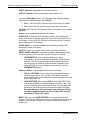
This is the default, information-only page. It displays all of the current
information about the supply that you are connected to:
Figure 5-12. SGI Home Page
•
•
•
•
•
•
•
5-16
The Model number, the Manufacturer, and the Serial Number of
your Ethernet power supply
Firmware Revision: the version of the Ethernet firmware that is
currently installed.
VISA Resource identifies the specific resource name used to
communicate via VISA (Virtual Instrument Software Architecture)
LXI™ Compliance: the version and instrument class of the LXI™
standard with which your power supply is compliant
Host Name: either the default or user-defined, network-unique
identity (Must be limited to 15 characters or less for LXI
compliance).
Description: either the default or user-defined description of the
power supply in use (you can change the description to suit your
needs, in the CONFIGURATION page, but it must be limited to 36
characters)
MAC Address: the power supply Ethernet’s unique hardware
address
M550129-03 Rev G
SG Series Programming
•
•
•
•
•
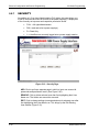
5.5.2
Ethernet Configuration and Remote Programming
IP Address: your power supply’s address actually in use at startup; can be statically configured, DHCP acquired (default), or AutoIP assigned (see description for CONFIGURATION page)
Subnet Mask: network segment your power supply is on
Gateway: IP address through which the instrument communicates
with systems that are not on the local subnet
DNS Server: IP address of the Domain Name System (DNS)
server
Listening Port: port number for the embedded Web server
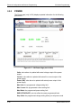
IP CONFIGURATION
Only users with FULL permissions shall have access to this Web page and
be allowed to configure the interface. You are only required to complete the
information for the parameters that you wish to change; all previously entered
and saved information remains by default.
Figure 5-13. SGI IP Configuration Page
Host Name: the default name includes the base model number of your
power supply, with the last four digits of the serial number. You may
change this name as long as it is unique (Host Name must be limited to
15 characters for LXI compliance) so that VXI-11 Discovery and any other
IP Discovery program can identify your specific device on your network.
M550129-03 Rev G
5-17
Ethernet Configuration and Remote Programming
To change:
SG Series Programming
Type the new name (15 characters maximum) in
the blank field provided and click Apply to
update (or make all desired changes before
clicking Apply).
Description: you may change the default factory setting to something
more meaningful to your current setup.
To change:
Type your customized description, up to 36
characters, in the blank field provided, and click
Apply to update (or make all desired changes
before clicking Apply).
TCP/IP Configuration: the power supply has two TCP/IP configurations
that can be set, Primary and Secondary. If the Primary Configuration is
not valid on your network, the power supply will attempt to try the
Secondary Configuration.
NOTE: The power supply will NOT try the Secondary Configuration if you
have selected the Primary Configuration options, Obtain an IP Address
Automatically and Auto IP Enabled.
You may statically assign an IP address as well as configure other
Ethernet/LAN parameters, or you may keep/return to its default setting for
automatic assignment of an IP address.
To assign:
Click the radio button next to Use a Static IP
Address to manually configure some or all of the
following the Ethernet/LAN parameters:
IP Address – input any standard IP address.
(Factory setting is 192.168.0.200). After clicking
Apply, you also must reset the power supply and
then exit and restart the Web browser to effect
this change. If you have changed the network
portion of the IP address, it may be necessary to
alter the network settings of your attached
computer to reconnect to the power supply.
Subnet Mask – input a value that identifies
which network segment your power supply is on,
consisting of 4 whole numbers, each ranging
from 0 through 255, separated by periods.
(Factory setting is 255.255.255.0, a class-C
network subnet mask). Click Apply to update (or
make all desired changes before clicking Apply).
Gateway – input the IP Address of any gateway
that stands between the instrument and any
other network entities that communicate with the
power supply. (No factory setting). Click Apply to
update (or make all desired changes before
clicking Apply).
DNS Server – input an IP address for the Domain
Name System (DNS) server. Click Apply to
5-18
M550129-03 Rev G
SG Series Programming
Ethernet Configuration and Remote Programming
update (or make all desired changes before
clicking Apply). This field has no factory setting.
Listening Port – input a port number for the
embedded Web server, ranging in value from
1025 – 65535. Click Apply to update (or make all
desired changes before clicking Apply). The
factory default port number is 9221.
To automate:
(To return to the default setting): Click the radio
button next to Obtain an IP Address
Automatically for dynamic address acquisition
from the DHCP server.
Auto IP Enabled: allows the power supply to
assign itself an IP address in the range from
169.254.0.1 to 169.254.255.254 with a subnet
mask of 255.255.0.0. If it is enabled, when there
is no DHCP server available, the power supply
will assign itself an IP address. However, please
keep in mind that when you select Obtain an IP
Address Automatically and you check Auto IP
Enabled in TCP/IP Primary Configuration, the
system will not try the Secondary Configuration.
To enable:
Click in the box to check; click again to uncheck
so that it is no longer enabled.
Example TCP/IP Configurations:
Primary: Use a Static IP Address
Secondary: Obtain an IP Address Automatically (DHCP)
At power-up the power supply will assign itself the configured static IP
address. If no other device is using the IP address, the power supply
continues with that static IP address. If some other device is using that
address, the power supply will move to Secondary and attempt to
acquire an IP address from a DHCP server repeatedly until it gets an
address.
Primary: Use a Static IP Address
Secondary: Obtain an IP Address Automatically (DHCP) and AutoIP
Enabled
At power-up the power supply will assign itself the static IP address. If
no other device is using the IP address, the power supply continues with
that static IP address. If some other device is using that address, the
power supply will move to secondary and attempt to acquire an IP
address from a DHCP server. If it cannot find a DHCP server to assign
an address, it will assign itself a link-local address. If no other device is
using that link-local address it will use it for 5 minutes minimum. At that
time, if it is already in communication with some other device, it will hold
onto that link-local address until the communication is finished and then
retry DHCP. Then, if DHCP is not available, the power supply will revert
to the last successful link-local address for another 5 minutes minimum.
M550129-03 Rev G
5-19
Ethernet Configuration and Remote Programming
SG Series Programming
Primary: Obtain an IP Address Automatically (DHCP) and AutoIP
Enabled
Secondary: no matter the setting, will never be attempted
At power-up the power supply will attempt to acquire an IP address from
a DHCP server. If it cannot find a DHCP server to assign an address, it
will assign itself a link-local address. If no other device is using that linklocal address, it will use it for 5 minutes minimum. At that time, if it is
already in communication with some other device, it will hold onto the
link-local address until the communication is finished and then retry
DHCP. If DHCP is not available, the power supply will revert to the last
successful link-local address for another 5 minutes minimum.
Primary: Obtain an IP Address Automatically (DHCP)
Secondary: Use a Static IP Address
At power-up the power supply will attempt to acquire an IP address from
a DHCP server. If it cannot find a DHCP server to assign an address, the
power supply will move to Secondary and assign itself the static IP
address. If no other device is using the IP address, the power supply
continues with that static IP address. If some other device is using the
static IP address, the power supply will move back to Primary and start
the entire operation again.
5-20
M550129-03 Rev G
SG Series Programming
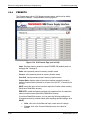
5.5.3
Ethernet Configuration and Remote Programming
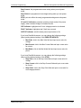
SETTINGS
The Settings page is available to users who have FULL, Read/Write or Read
Only access to at least one power supply (Read Only users can make no
changes to the settings). In this page you will see continuous updates (2-5
times per second) of the actual voltage output (value displayed on the left)
and the actual live current output (value displayed to the right).
Figure 5-14. Settings Page
Voltage: value above is updated with actual voltage output of the power
supply
Current: value above is updated with actual live current output
Set V: the programmed voltage setting
Set I: the programmed current setting
Set OVP: the programmed over voltage protection setting
APPLY: puts into effect the newly input settings
CC and CV indicators: presently operating output mode of the power
supply, either constant voltage or constant current.
OVP indicator: highlighted red if over voltage protection is activated
M550129-03 Rev G
5-21
Ethernet Configuration and Remote Programming
SG Series Programming
FAULT indicator: highlighted red if fault has occurred
OUTPUT indicator: solid-lit shows power output status is On
If you have Read/Write access, you can change the following settings
(after inputting desired settings, click APPLY):
•
Set V – click in the Set V field and input a new value for voltage.
•
Set I: click in the Set I field and input a new value for current.
Set OVP: click in the Set OVP field and input a new value for over voltage
protection.
Output – click the applicable button(s) as follows:
CLEAR OVP: to clear the OVP indication/condition after clearing the
cause of the event. The power supply will revert to the last saved values
for Voltage, Current, and OVP. Be sure to reset these values, if desired,
before clearing an OVP condition.
CLEAR FAULT: to clear the hardware fault indication/condition after
clearing the cause of the event.
OUTPUT: to turn on or off the power output (see Output indicator)
FRONT PANEL LOCKOUT: to prevent or enable changes being made
via the front panel (LED to the left is lit when Lockout is in effect).
•
INSTRUMENT ID: click to identify which power supply
(instrument) in a rack of equipment corresponds to the Channel
selected. The LED to the left of this button indicates whether or
not this function is turned on (ON causes the instrument’s rear
panel NET LED to flash; the flashing continues until you click
INSTRUMENT ID again).
Power-on Default: click the applicable button(s) as follows:
•
RECALL SETTINGS: click to restore the programmed Power-on
defaults into the Set V, Set I and Set OVP settings, and to the
power supply output (these defaults are those that were last saved
prior to this Power-on).
•
SAVE SETTINGS: after clicking APPLY, click SAVE SETTINGS
to save the presently set values displayed in the Set V, Set I and
Set OVP fields into non-volatile flash. (If only one new setting had
been input, the other previously saved values remain the same).
Be aware that these then become the new power-on settings
that will be applied at power-up time and after OVP reset as
described in “Clear OVP” above.
NOTE: When you click SAVE SETTINGS, you will get a pop-up alert
(Figure 5-15) telling you that saving a non-zero voltage may cause the power
supply to power-on with a voltage on its output terminals after a restart or
power cycle.
5-22
M550129-03 Rev G
SG Series Programming
Ethernet Configuration and Remote Programming
Figure 5-15. Alert Message for Save Settings
SCPI COMMAND SECTION:
SEND COMMAND: (not to be used with any command that provides a
response) input a properly formatted SCPI command (Section 6) in the
upper of the two windows and click this button to send the command.
SEND AND READ: for queries, input a properly formatted SCPI query
command in the upper of the two windows, and click this button to send
the command and read the response in the lower of the two windows.
SCPI Command History: a history of the last few commands sent to the
power supply are remembered by the system and listed in this area. You
can click on a command to have it be pasted in the command window.
CLEAR RESPONSES: click this button to clear the response window of
previous responses.
M550129-03 Rev G
5-23
Ethernet Configuration and Remote Programming
5.5.4
SG Series Programming
STATUS
The Status page displays updated information for the following parameters:
Figure 5-16. Status Page
Output: displays the power output status, ON or OFF
Trigger: set up by SCPI commands, displays whether the Trigger state is
OFF, ARMED, or TRIGGERED.
OVP: displays Read Only status of over voltage protection, either OK
(normal) or TRIPPED.
FAULT: displays Read Only status of over temperature condition, either
OK (normal) or TRIPPED.
Command Error: displays command and syntax errors that are queued
in the supply.
READ NEXT ERROR: each click brings the next error into the Command
Error display, until no other errors are in the queue.
CLEAR MESSAGES: click this button to clear the Command Error
message window of past messages.
5-24
M550129-03 Rev G
SG Series Programming
Ethernet Configuration and Remote Programming
Last Calibration Date: displays the date that the power supply
(instrument) was last calibrated; configurable with SCPI commands,
normally at the time of calibration.
Next Calibration Date: displays the date that the power supply should be
calibrated next; also configurable with SCPI commands, normally
calculated at time of calibration.
Ping Echo: except for Read Only users, allows turning echo ability On or
Off, depending on whether or not you want the supply to respond to a
Ping command from another device on the network. The default setting
for Ping Echo is response enabled. Click the OFF radio button if you do
not want the supply to respond to a ping.
Ping Remote IP Address: allows you to input an IP address of another
device in the system
Ping: click this button to ping the device at the address that you entered
in the Ping Remote IP Address field.
Response: displays the result of your ping. For Example, if the Ping
Address were 69.36.230.190, the Response window would display:
Pinging :69.36.230.190 Response Took 0 ticks
Or
Ping Failed (if the host specified is not in the network)
CLEAR RESPONSES: click this button to clear the Response window of
past ping responses.
M550129-03 Rev G
5-25
Ethernet Configuration and Remote Programming
5.5.5
SG Series Programming
POWER
The Power page (only in SGI) displays updated information for the following
parameters:
Figure 5-17. SGI Power Page (not in SGA)
Volts: value above is updated with actual voltage output of the power
supply
Current: value above is updated with actual live current output of the
power supply
Power (kW): value above is updated with actual power output of the
power supply
Max Volts: the programmed voltage setting limit
Max Current: the programmed current setting limit
Max Watts: the programmed power setting limit
EXECUTE/UPDATE: puts into effect the newly programmed limits
Stop Volts: the programmed voltage setting when you exit power mode
5-26
M550129-03 Rev G
SG Series Programming
Ethernet Configuration and Remote Programming
Stop Current: the programmed current setting when you exit power
mode
Stop OVolt: the programmed overvoltage setting when you exit power
mode
STOP: puts into effect the newly programmed settings and exits power
mode
CC and CV indicators: presently operating output mode of the power
supply, either constant voltage or constant current.
OVP indicator: highlighted red if over voltage protection is activated
FAULT indicator: highlighted red if fault has occurred
OUTPUT indicator: solid-lit shows power output status is On
If you have Read/Write access, you can change the following settings
(after inputting desired settings, click EXECUTE/UPDATE):
•
Max Volts: click in the Max Volts field and input a new value for
voltage.
•
Max Current: click in the Max Current field and input a new value
for current.
•
Max Watts: click in the Max Watts field and input a new value for
power.
If you have Read/Write access, you can change the following settings
(after inputting desired settings, click STOP):
•
Stop Volts: click in the Stop Volts field and input a new value for
voltage.
•
Stop Current: click in the Stop Current field and input a new value
for current.
•
Stop OVolt: click in the Stop OVolt field and input a new value for
overvoltage protection.
M550129-03 Rev G
5-27
Ethernet Configuration and Remote Programming
5.5.6
SG Series Programming
PRESETS
The Presets page (only in SGI) displays stored values, which can be edited,
saved and/or recalled. The parameters for this page are:
Figure 5-18. SGI Presets Page (not in SGA)
Index: Displays memory locations named POWER ON (default power on
settings) and 1 through 9
Volts: value presently stored in memory location name
Current: value presently stored in memory location name
Over Volt: value presently stored in memory location name
Output State: displays state of the output condition presently stored in
memory location name (indicator is an open circle for OFF or a solid circle
for ON)
SAVE: saves the input values into their respective location name memory
(Must have Read/Write access)
EXECUTE: recalls the following settings into operation from its respective
memory location name (Must have Read/Write access)
If you have Read/Write access, you can save the following settings into
its respective memory location name (after inputting desired settings, click
SAVE):
5-28
•
Volts: click in the Volts field and input a new value for voltage.
•
Current: click in the Current field and input a new value for
current.
M550129-03 Rev G
SG Series Programming
Ethernet Configuration and Remote Programming
•
Over Volt: click in the Over Volt field and input a new value for
overvoltage protection.
•
Output State: click in the Output State field to change the state of
the output condition indicator. (indicator is an open circle for OFF
or a solid circle for ON)
M550129-03 Rev G
5-29
Ethernet Configuration and Remote Programming
5.5.7
SG Series Programming
SECURITY
Accessible only if you have Administrative (Full) rights, this page allows you
to set up new user accounts for access to the power supply(s). It displays all
of the currently set up users and respective permission levels.
•
FULL = full rights/Administrator
•
RW = read and write to power supply(s)
•
R = Read Only
•
-L = identifies user currently logged onto a power supply session.
Figure 5-19. Security Page
ADD: Click to pull up a separate page in which to input new users with
passwords and permission levels. (See Figure 5-20).
REMOVE: Click to delete selected user after first highlighting their User
Name row. The Admin user cannot be removed.
EDIT: Click to change settings (name/permissions) for selected user after
first highlighting their User Name row. This brings up the Edit Existing
User window (Figure 5-21).
5-30
M550129-03 Rev G
SG Series Programming
Ethernet Configuration and Remote Programming
ADD NEW USER
Accessible from the Security Page by clicking the ADD button, this page
is allows you (a Full permissions user) to add new users with their
passwords and permission levels.
Figure 5-20. Add New User Window from Security Page
To add:
1. Input appropriate information in User ID (case-sensitive,
limited to 14 characters), in Password (case sensitive,
limited to 9 characters), and in Re-enter Password fields.
2. Select permission level from the Permission dropdown.
3. To accept into the system, click SUBMIT or tap the ENTER
key.
In the ADD NEW USER: line, you will see a message that [new user
name] was added successfully, or a message that it was unsuccessful
and the reason.
RESET: click to clear the fields where you input information.
CANCEL: click to return to the Security page; a message displays
verifying that the Add New User was cancelled. This button does NOT
“undo” previous successful submit operations.
M550129-03 Rev G
5-31
Ethernet Configuration and Remote Programming
SG Series Programming
EDIT EXISTING USER
Accessible from the Security Page by clicking the EDIT button after first
selecting the user’s name, this page allows you (a Full permissions user)
to edit the parameters for an existing user.
Figure 5-21. Edit Existing User Window from Security Page
When this page appears, the fields are populated with the selected user’s
existing parameters.
To edit:
1. Input appropriate information, as desired, in User ID
(case-sensitive, limited to 14 characters), in Password
(case sensitive, limited to 9 characters), and/or in Reenter Password fields.
2. Select permission level from the Permission dropdown.
3. To accept into the system, click SUBMIT or tap the
ENTER key.
If your edit was successful, you will return to the Security page with a
message to that effect.
If there is an error in the editing process, you will stay in the Edit Existing
User page, and you will see a message in the EDIT EXISTING USER:
line, describing the reason for the error.
5-32
•
RESET: click to clear the fields where you input information.
•
CANCEL: click to return to the Security page; a message displays
verifying that the User Edit was cancelled. This button does NOT
“undo” previous successfully submitted operations.
M550129-03 Rev G
SECTION 6
IEEE 488.2 GPIB/RS232/ETHERNET
AND SCPI COMMAND OPERATION
6.1
INTRODUCTION
This section describes the operation of the Digital Interface Adapter (DIA)
for both GPIB and Ethernet, by using the IEEE 488.2, Ethernet and SCPI
command sets, which provide programming, query, and status
commands that facilitate remote control of the power supply.
6.2
REGISTER DEFINITIONS
The applicable DIA (for either GPIB or Ethernet) supports the IEEE
488.2 GPIB, Ethernet and SCPI 1995.0 status reporting data
structures. These structures are comprised of status registers and
status register enable mask pairs. The following sections describe
these pairs.
6.2.1
SCPI Status Byte
The SCPI Status Byte registers the status of the instrument, in one of
seven bits described in Table 6-1. Read the SCPI Status Byte status
register by issuing either the *STB? command or a serial poll. Clear the
Status Byte status register by issuing the *CLS command.
Configure the DIA to request service from either the GPIB or Ethernet
controller, by setting the appropriate bits in the Service Request Enable
Register (SRE), which has the same bit pattern as the Status Byte.
Modify the SRE register by issuing the *SRE <mask> command, and
read the SRE register by issuing the *SRE? command. For example, if
the SRE register is set to 0x10 (MAV), when the DIA unit has a message
available, the Status Byte register will contain 0x50 (RQS and MAV) and
the SRQ (SRQ is supported only on GPIB; not Ethernet or RS232) line
will be asserted to indicate a request for service. See Table 6-1 and refer
to SCPI Status Implementation, page 8-1, for further information.
M550129-03 Rev G
6-1
SCPI Command Operation
SG Series Programming
Table 6-1. SCPI Status Byte
Bit
Hex Value
0
0x01
1
0x02
2
0x04
3
0x08
4
0x10
5
0x20
6
0x40
7
0x80
6-2
Description
Not used.
Protection Event Status flag. Indicates the selected protection
event occurred.
Error/event queue message available. Set when any error/event is
entered in the System Error Queue. It is read using the
SYSTem:ERRor? query.
Questionable Status flag. Indicates the quality of the current data
being acquired. This bit is not used.
Message available (MAV). Indicates a message is available to
read via serial or Ethernet.
Standard Event Status Register (ESR). Summary bit for the ESR.
Set when any of the ESR bits are set and cleared when the ESR is
read.
Request Service flag (RQS) for serial polling or Master Summary
Status (MSS) in response to *STB? If service requests are enabled
(with the *SRE command), this bit represents the RQS and will be
sent in response to a serial poll, then cleared. If RQS is not
enabled, the bit represents the MSS bit and indicates the device
has at least one reason to request service. Even though the device
sends the MSS bit in response to a status query (*STB?), it is not
sent in response to a serial poll. It is not considered part of the
IEEE-488.1 Status Byte.
Operation Status flag. Indicates the current operational state of the
unit. This bit is not used.
M550129-03 Rev G
SG Series Programming
SCPI Command Operation
Standard Event Status Register (ESR)
6.2.2
Read the Standard Event Status Register (ESR) by issuing the *ESR?
command. Reading this register or issuing a *CLS command will clear
the ESR. Use the *ESE (Standard Event Status Enable Register) to
enable corresponding ESR bits to be summarized in the summary bit of
the SCPI Status byte. To configure the Digital Interface Adapter (DIA) to
generate service requests based on the ESR, both the Standard Event
Status Enable Register and the Service Request Enable Register must
be programmed. See , and refer to Section 5 for further information.
Table 6-2. Standard Event Status Register
6.2.3
Bit
Hex Value
0
0x01
Operation Complete
1
0x02
Request Control - not used
2
0x04
Query Error
3
0x08
Device Dependent Error
4
0x10
Execution Error (e.g., range error)
5
0x20
Command Error (e.g., syntax error)
6
0x40
User Request - not used
7
0x80
Power On
Description
Protection Condition and Protection Event Status
Register
87B
These two registers have the same bit meanings, but they differ in
function.
Read
the
Protection
Condition
Register
by
issuing
the
STAT:PROT:COND? command. This command gives the present status
condition of the power hardware, so the data is not latched. It is meant to be
used as a polling register.
Read the Protection Event Status Register by issuing the
STATus:PROTection:EVENt? command. Reading this register clears the
Protection Event Status Register. Or clear the Protection Event Status
Register by issuing a *CLS command or a *RST command. Bits in the
Protection Event Status Register will be set only when the corresponding
bit in the Protection Event Status Enable Register is set and the
corresponding event occurs. The status is then latched and will remain in
that state until it is read or cleared due to some command action. (Set the
Enable Register with the STATus:PROTection:ENABle <mask> command,
and query the Enable Register with the STATus:PROTection:ENABle?
query).
To configure the Digital Interface Adapter (DIA) to generate service
M550129-03 Rev G
6-3
SCPI Command Operation
SG Series Programming
requests based on the Protection Event Status Register, program both the
Protection Event Status Enable Register and the Service Request Enable
Register (*SRE). For further information, refer to the table below, and to
SCPI Status Implementation page 8-1.
Table 6-3. Protection Condition and Event Status Registers
6-4
Bit
Hex Value
0
0x01
Constant voltage operation
1
0x02
Constant current operation
2
0x04
Not used
3
0x08
Overvoltage protection tripped
4
0x10
Overtemperature protection tripped
5
0x20
Supply external shutdown active
6
0x40
Foldback mode operation
7
0x80
Remote programming error
Description
M550129-03 Rev G
SG Series Programming
6.2.4
SCPI Command Operation
Operation Status and Questionable Status
Registers
The Operation Status and Questionable Status Registers will always
return 0 when queried. The Operation Status Enable and Questionable
Status Enable Registers can be programmed and queried to allow SCPI
compatibility but have no effect on the Operation Status and Questionable
Status Registers.
6.2.5
Error/Event Queue
The Digital Interface Adapter (DIA) maintains an Error/Event Queue as
defined by SCPI. The queue holds up to 10 error events. It is queried
using the SYSTem:ERRor? command which reads in a First In/First Out
(FIFO) manner. The read operation removes the entry from the queue.
The *CLS command will clear all entries from the queue.
The following error codes are defined in the SCPI 1995.0 specification and
are supported by the DIA. Error codes are in the range of [-32768,
32767]. SCPI reserves the negative error codes and 0, while error codes
greater than 0 are device specific errors.
Table 6-4. SCPI Error Codes
Error Code
206
205
204
203
202
Description
No channels setup to trigger
This means that an attempt was made to trigger the DIA using the
TRIG:TYPE <1|2|3> command when there are no armed trigger settings.
This error is not generated when the GET is received, even when there are
no armed trigger settings.
GPIB GET not allowed during message
This error means that the GPIB G(roup) E(xecute) T(rigger) multiline
command was errantly generated by the system computer while or very
shortly after a message is or was sent. Give a few milliseconds after a
message was sent before attempting a GET; and never send a GET during
the midst of a message transfer over the GPIB.
GPIB IFC caused warm boot
This error relates to the GPIB IFC signal, and is available only in
association with a proprietary command.
Hardware watchdog warm boot
This error is caused by a hardware fault either in the power supply proper,
or on the DIA. One possible explanation might be that the mains power to
the supply was interrupted for a short but sufficient time to cause the DIA
processor to reset and re-boot. Also, it might be possible to generate this
error by a very momentary off action of the front panel power switch.
Foreground watchdog warm boot
This error means that the internal firmware on the DIA found an internal
error condition that halted processing; to force resumption of processing, a
warm boot was required.
M550129-03 Rev G
6-5
SCPI Command Operation
Error Code
201
-292
Description
Unexpected warm boot
This error means that the DIA processor experienced a warm boot that
was unexpected, and it may indicate an internal crash of the DIA
processor.
Incompatible unit type
This error is not used. It cannot occur.
Incompatibility error
This error is not used. It cannot occur.
No error
The error queue is empty.
Syntax error
An unrecognized command or data type was encountered.
Parameter not allowed
More arguments than expected were received.
Invalid string data
Incorrect password. Manufacturer, model, or serial number string was
more than 16 characters. Invalid mnemonic.
Invalid block data
The expected number of data values was not received.
Execution error
An error/event number in the range [-299,-200] indicates that an error has
been detected by the instruments execution control block. The occurrence
of any error in this class shall cause the execution error bit (bit 4) in the
Event Status Register to be set. An execution error can be the result of:
• A <program data> element out of range, such as programming 35 volts
in a 33 volt device.
• A command could not be executed due to the current condition of the
device.
Command protected
Attempted to store calibration values to EEPROM without unlocking.
Settings conflict
Attempted to set output greater than soft limits or to set soft limits less than
output.
Data out of range
Parameter exceeded range of valid values.
Out of memory
There is not enough memory to perform the requested operation.
Hardware missing
A legal command or query could not be executed because of a hardware
fault.
Program currently running
A legal command or query could not be executed because a function is
currently running.
Referenced name does not exist
-293
Referenced name already exists
-316
Checksum error
102
100
0
-102
-108
-151
-161
-200
-203
-221
-222
-225
-241
-284
6-6
SG Series Programming
M550129-03 Rev G
SG Series Programming
Error Code
-330
-340
-350
-360
SCPI Command Operation
Description
Self-test failed
A self-test failure has occurred.
Calibration failed
Error during calculation of calibration values occurred.
Queue overflow
The error queue can contain up to 10 entries. If more than 10 error/event
conditions are logged before the SYSTem:ERRor? query, an overflow will
occur; the last queue entry will be overwritten with error -350. When the
queue overflows, the least recent error/events remain in the queue and the
most recent error/events are discarded.
Communication error
Communications to a channel was disrupted.
M550129-03 Rev G
6-7
SCPI Command Operation
6.2.6
SG Series Programming
Serial Poll Operation
Performing a serial poll will not modify the Status Byte other than to clear
the RQS (bit 6) for a Digital Interface Adapter (DIA) requesting service.
Queries affecting the Status Registers and subsequent serial poll are
described below:
• *STB? clears the Status Byte
• *ESR? clears the ESR and bit 5 of the Status Register
• SYSTem:ERRor? clears bit 2 of the Status Register if the queue is
empty
6.3
ETHERNET LXI™, VXI-11, AND SCPI
CONFORMANCE INFORMATION
The Digital Interface Adapter (DIA) for the Ethernet is IEEE-802.3 and
LXI™ class C compliant. The syntax of all SCPI commands implemented
by the SG power supplies and documented in this manual, are either
SCPI confirmed in the SCPI 1995 Specification, Volume 2: Command
Reference, or they are customized commands not part of the SCPI
definition. None of the commands implemented by the SG power
supplies are classified as SCPI approved commands (approved by the
SCPI Consortium but not contained in the SCPI version to which the SG
power supplies conform).
To document whether the syntax of each command is SCPI compliant or
not, this manual provides a column, labeled “SCPI”, in each command
reference table. A “C” in the “SCPI” column means that the command
syntax is SCPI compliant; an “N” in the “SCPI” column means that the
command syntax is not part of the SCPI definition.
6.3.1
Parameter Definitions
The following table describes the format of the command arguments,
when applicable.
PARAMETER DEFINITIONS
Type
<boolean>
<NR1>
<NRf>
<string>
6-8
Valid Arguments
“ON” or 1. “OFF” or 0.
The data format <NR1> is defined in IEEE 488.2 for integers.
Zero, positive and negative integer numeric values are valid data.
The data format <NRf> is defined in IEEE 488.2 for flexible Numeric
Representation. Zero, positive and negative floating point numeric
values are some examples of valid data.
Characters enclosed by single or double quotes.
M550129-03 Rev G
SG Series Programming
6.3.2
SCPI Command Operation
Units
The SGA/SGI power supplies will accept the following units as suffixes to
numeric values:
UNITS
Type of Unit
Valid Suffix
Voltage
“VOLTS” or “volts”, “V” or “v”, “MV” or “mv” or “mV”
Current
“AMPS” or “amps”, “A” or “a”, “MA” or “ma” or “mA”
Time
“SEC” or “sec”, “S” or “s”, “MS” or “ms”, “MIN” or “min”
Frequency
“HZ” or “hz”
The default units are VOLTS, AMPS, SEC, and HZ.
For example, “SOUR:VOLT 1” programs 1 volt.
To program in units of millivolts, type “SOUR:VOLT 1mV”.
6.3.3
Conventions
SCPI uses the conventions where optional commands and parameters
are enclosed by “[ ]”. Additionally the shorthand version of a command is
indicated by capital letters.
For example,
SOURce:VOLTage[:LEVel][:IMMediate][:AMPLitude] 120.0
can be written as
SOURce:VOLTage 120.0
or
SOUR:VOLT 120.0
6.3.4
Queries
The query syntax is identical to the command syntax with a “?” appended.
For example, to query the programmed voltage, send the string:
SOURce:VOLTage?. A subsequent device read will return a value such
as “33.000”. All queries are terminated with a carriage return and line feed
(0x0D 0x0A). When the power supply has nothing to report, its output
buffer will contain two ASCII characters: a carriage return and linefeed (in
decimal the values are: <13><10>).
M550129-03 Rev G
6-9
SCPI Command Operation
6.4
SG Series Programming
IEEE 488.2 COMMON COMMAND
SUBSYSTEM
The following commands are common to all SCPI instruments and
declared mandatory by IEEE 488.2. In the following table, the Digital
Interface Adapter (DIA) is defined as the “device” on the GPIB bus.
Command
Description
*ESE?
Clears all status reporting data structures including the Status Byte,
Standard Event Status Register, and Error Queue. The
STAT:PROT:ENAB (protection event enable register) is cleared by
this command; other enable registers are not cleared by this
command.
Sets the value of the Standard Event Status Enable Register that
determines which bits can be set in the Standard Event Status
Register. See section 6.2.2 for valid values.
Returns the integer value of the Standard Event Status Enable
Register. See section 6.2.2 for valid values.
*ESR?
Response: <0+NR1>
Returns the integer value of the Standard Event Status Register.
The ESR and the Status Byte ESR bit are cleared. See section
6.2.2 for valid values.
*CLS
*ESE
<0+NR1>
Response: <0+NR1>
Returns the device identification as an ASCII string.
*IDN?
Response: <Manufacturer>, <model>, <serial number>,
<DCI firmware version> <AI firmware version>
*OPC
Example: Sorensen, SGA100/150C-1AAA, 0622A00111,
1.00,1.00
Enables the Operation Complete bit of the Standard Event Status
Register to be set when all pending operations are complete. See
section 6.2.2.
Returns the integer value “1” when all pending operations are
complete. See section 6.2.2.
C*OPC?
*RCL
<integer>
*RST
*SAV
<integer>
6-10
Response: <0+NR1>
SGI ONLY - Specifies the preset storage location (0 through 9) from
which to load into the supply’s Voltage, Current, Overvoltage
Protection, and Output State settings. Preset location 0 stores the
supply’s power on default.
Resets the supply to its Power ON (PON) state.
Clears all status reporting data structures including the Status Byte,
Standard Event Status Register, and Error Queue. The
STAT:PROT:ENAB (protection event enable register) is cleared by
this command; other enable registers are not cleared by this
command.
Specifies the preset storage location (0 through 9) to store the
supply’s existing Voltage, Current, Overvoltage Protection, and
Output State settings. Preset location 0 stores the supply’s power
up default.
M550129-03 Rev G
SG Series Programming
Command
*SRE
<0+NR1>
*SRE?
*STB?
*TST?
*WAI
M550129-03 Rev G
SCPI Command Operation
Description
Sets the value of the Service Request Enable Register, which
determines which bits in the Status Byte will cause a service
request from the device. See section on Status Byte for valid
values.
Returns the integer value of the Service Request Enable Register.
See section on Status Byte for valid values. Values range from 063 or 128-191.
Response: <0+NR1>
Returns the integer value of the Status Byte with bit 6 representing
the Master Summary Status (MSS) instead of RQS. The MSS bit
acts as a summary bit for the Status Byte and indicates whether the
device has at least one reason to request service based on the
MAV and the ESR bits. The Status Byte is cleared. See section on
Status Byte for valid values. Values range from 0-255.
Response: <0+NR1>
Sets the device to execute an internal self-test and return the
integer value of the results. Value of “0” indicates no errors.
Response: <0+NR1>
Sets the device to wait until all previous commands and queries are
complete before executing commands following the *WAI
command.
6-11
SCPI Command Operation
6.5
SG Series Programming
SOURCE SCPI COMMAND SUBSYSTEM
This section first presents a tree summary of the SOURce commands
and then provides a tabular description.
6.5.1
SOURCE SCPI Command Summary
SOURce
:CURRent
:CURRent?
[:LEVel]
[:LEVel?]
[:IMMediate]
[:IMMediate?]
[:AMPLitude] <NRf>
[:AMPLitude?]
:LIMit
:LIMit?
[:AMPLitude] <NRf>
[:AMPLitude?]
:RAMP <NRf> <NRf>
:RAMP?
:ABORt
:ALL?
:HTRIGgered <NRf>
:HTRIGgered?
:TRIGgered <NRf> <NRf>
:TRIGgered?
:TRIGgered
:TRIGgered?
:CLEar
:AMPLitude <NRf>
:AMPLitude?
:POWer (Available only with SGI power supplies – see Section 6.13.)
:POWer? (Available only with SGI power supplies – see Section 6.13.)
:LEVel
:LEVel?
:IMMediate
:IMMediate?
:AMPLitude <NRf>
:AMPLItude?
:TIMeout?
:VOLTage
:VOLTage?
[:LEVel]
[:LEVel?]
[:IMMediate]
[:IMMediate?]
[:AMPLitude] <NRf>
[:AMPLitude?]
:LIMit
:LIMit?
[:AMPLitude] <NRf>
[:AMPLitude?]
:PROTection
6-12
M550129-03 Rev G
SG Series Programming
SCPI Command Operation
:PROTection?
[:LEVel] <NRf>
[:LEVel?]
:TRIPped?
:STATe?
:CLEar
:RAMP <NRf> <NRf>
:RAMP?
:ABORt
:ALL?
:HTRIGgered <NRf> <NRf>
:HTRIGgered?
:TRIGgered <NRf> <NRf>
:TRIGgered?
:TRIGgered
:TRIGgered?
:CLEar
:AMPLitude <NRf>
:AMPLitude?
6.5.2
SOURCE SCPI Command Reference
The letter “C” in the “SCPI” column means that the command syntax is
SCPI compliant; an “N” in the “SCPI” column means that the command
syntax is not part of the SCPI definition.
Command
SOURce
:CURRent
:CURRent?
[:LEVel]
[:LEVel?]
[:IMMediate]
[:IMMediate?]
[:AMPLitude]
<NRf>
[:AMPLitude?]
:LIMit
:LIMit?
[:AMPLitude]
<NRf>
[:AMPLitude?]
:RAMP <NRf> <NRf>
:RAMP?
:ABORt
M550129-03 Rev G
Description
Source subsystem.
Sets the output current in amps (default) or in milliamps.
Returns the output current in amps or in milliamps
Sets the output current in amps (default) or in milliamps.
Returns the output current in amps or in milliamps.
Sets the output current in amps (default) or in milliamps.
Returns the output current in amps or in milliamps
SCPI
C
C
C
C
C
C
C
Sets the output current in amps (default) or in milliamps.
C
Returns the output current in amps or in milliamps
Sets an upper soft limit on the programmed output current
for the supply. The soft limit prevents the supply from being
inadvertently programmed above the soft limit, thus
providing a method for protecting the load against
damaging currents.
Returns the upper soft limit on the programmed output
current for the supply.
Sets an upper soft limit on the programmed output current for
the supply.
Returns the upper soft limit on the programmed output
current for the supply.
Sets the output current to ramp from the present value to the
specified value (first argument) in the specified time (second
argument). See Ramp Function description below.
Returns 1 if the ramp is in progress, and 0 if the ramp is
completed.
Aborts ramping and clears trigger mode.
C
C
C
C
C
N
N
N
6-13
SCPI Command Operation
Command
:ALL?
SG Series Programming
Description
Returns the ramping status of all channels.
:HTRIGgered <NRf> Sets the value of the output current to ramp to be
implemented when the hardware trigger is received.
Returns the value of the output current to ramp to be
:HTRIGgered?
implemented when the hardware trigger is received.
Sets the output current to ramp from the present value to
:TRIGgered <NRf>
the specified value (first argument) in the specified time
(second argument) upon the trigger command. See Ramp
<NRf>
description below.
Returns the value that the output current is to ramp to (first
:TRIGgered?
value) and the time that it is to ramp (second value) upon
the trigger command.
Sets the output voltage to the values stored by the
:TRIGgered
SOURce: CURRent:TRIGger:AMPLitude command.
Returns the current level that will be set upon receipt of the
:TRIGgered?
trigger.
Clears the value stored by the
:CLEar
SOURce:CURRent:TRIGger:AMPLitudecommand.
Stores the value of the output current to be set when the
:AMPLitude <NRf>
SOURce: CURRent:TRIGGered command is sent.
Returns the stored value of the output current to be set
:AMPLitude?
when the SOURce: CURRent:TRIGGered command is
sent.
:POWer (in SGI only)
See Section 6.13.2.
:POWer? (in SGI only)
Returns the integer value 1 (timeout since last query) or 0
:TIMeout?
(no timeout) of the timeout status of the channel.
Sets the output voltage of the supply in volts (default) or in
:VOLTage
millivolts.
Returns the output voltage of the supply in volts or in
:VOLTage?
millivolts.
Sets the output voltage of the supply in volts (default) or in
[:LEVel]
millivolts.
Returns the output voltage of the supply in volts or in
[:LEVel?]
millivolts.
Sets the output voltage of the supply in volts (default) or in
[:IMMediate]
millivolts.
Returns the output voltage of the supply in volts or in
[:IMMediate?]
millivolts.
[:AMPLitude]
Sets the output voltage of the supply in amps (default) or in
<NRf>
milliamps.
Returns the output voltage of the supply in amps or in
[:AMPLitude?]
milliamps.
Sets the upper soft limit on the programmed output voltage.
The soft limit prevents the supply from being inadvertently
:LIMit
programmed above the soft limit, thus providing a method
for protecting the load against damaging voltages.
Returns the upper soft limit set on the programmed output
:LIMit?
voltage.
[:AMPLitude]
Sets the upper soft limit on the programmed output voltage.
<NRf>
Returns the upper soft limit on the programmed output
[:AMPLitude?]
voltage.
:PROTection
Sets the overvoltage protection trip point in volts (default) or
6-14
SCPI
N
N
N
C
C
C
C
C
C
C
N
C
C
C
C
C
C
C
C
C
C
C
C
C
M550129-03 Rev G
SG Series Programming
Command
SCPI Command Operation
Description
in millivolts.
Returns
the set overvoltage protection trip point in volts
:PROTection?
(default) or in millivolts.
Sets the overvoltage protection trip point in volts (default) or
[:LEVel] <NRf>
in millivolts.
Returns the set overvoltage protection trip point in volts or in
[:LEVel?]
millivolts.
Returns 1 (TRIPPED) or 0 (UNTRIPPED) state of the
:TRIPped?
overvoltage protection CIRCUIT.
Returns the state 1 (ON) or 0 (OFF) If the overvoltage
:STATe?
protection is enabled.
:CLEar
Clears the overvoltage protection CIRCUIT.
Sets the output voltage to ramp from the present value to the
:RAMP <NRf> <NRf>
specified value (first argument) in the specified time (second
argument). See Ramp Function description Section 6.5.3.
Returns 1 if the ramp is in progress, and 0 if the ramp is
:RAMP?
completed.
:ABORt
Aborts ramping and clears trigger mode.
:ALL?
Returns the ramping status of all channels.
:HTRIGgered <NRf> Sets the value of the output voltage ramp to be implemented
when the hardware trigger is received.
Returns the value of the output voltage ramp to be
:HTRIGgered?
implemented when the hardware trigger is received.
M550129-03 Rev G
SCPI
C
C
C
C
C
C
N
N
N
N
N
N
6-15
SCPI Command Operation
SG Series Programming
Command
:TRIGgered <NRf>
<NRf>
:TRIGgered?
:TRIGgered
:TRIGgered?
:CLEar
:AMPLitude <NRf>
:AMPLitude?
6.5.3
Description
SCPI
Sets the output voltage to ramp from the present value to
the specified value (first argument) in the specified time
(second argument) upon the trigger command. See
description of the Ramp Function below.
Returns the output voltage to ramp
Sets the output voltage to the values stored by the
SOURce:VOLTage:TRIGger:AMPLitude command.
Returns the voltage level that will be set upon receipt of the
trigger.
Clears the value stored by the
SOURce:VOLTage:TRIGger:AMPLitude command.
Stores the value of the output current to be set when the
SOURce:VOLTage:TRIGGered command is sent.
Returns the stored value of the output current to be set
when the SOURce:VOLTage:TRIGGered command is sent.
N
N
C
C
C
C
C
RAMP FUNCTION
The ramp function allows the user to transition from one voltage or
current to another linearly in a specified time period (100 ms - 99 sec with
100 ms programming resolution). A unit may ramp only voltage or
current, not both at a given time.
For example, SOUR:VOLT:RAMP:TRIG 1 1 followed by
SOUR:CURR:RAMP:TRIG 2 2 will cause the unit to ramp only the output
current to 2 amps in 2 seconds upon the TRIG:RAMP command.
VOLTAGE RAMPING TO A HIGHER VOLTAGE
Requires a programmed current of at least 20% of the full scale value.
Settings less than 20% will significantly lengthen the ramp time due to
charging of the large capacitance in the output section of the power
supply.
VOLTAGE RAMPING TO A LOWER VOLTAGE
Requires an appropriate resistive load. The discharge rate of the large
capacitance in the output section of the power supply, plus other user
capacitance, significantly lengthens the ramp time.
CURRENT RAMPING
Requires an appropriate resistive load.
6-16
M550129-03 Rev G
SG Series Programming
6.6
SCPI Command Operation
MEASURE SCPI COMMAND SUBSYSTEM
This section first presents a tree summary of the MEASure commands
and then provides a tabular description.
6.6.1
MEASURE SCPI Command Summary
MEASure
:CURRent
:CURRent?
:AVErage <value>
:AVErage?
:POWer? (Available only with SGI power supplies – see Section 6.13.)
:VOLTage
:VOLTage?
:AVErage <value>
:AVErage?
6.6.2
MEASURE SCPI Command Reference
The letter “C” in the “SCPI” column means that the command syntax is SCPI
compliant; an “N” in the “SCPI” column means that the command syntax is not
part of the SCPI definition.
Command
MEASure
:CURRent?
:CURRent
:AVErage
<NR1>
:AVErage?
:POWer? (SGI
only)
:VOLTage?
:VOLTage
:AVErage
<NR1>
:AVErage?
M550129-03 Rev G
Description
Measure subsystem.
Returns the floating point value of the DC output current in amps.
Measure Current subsystem.
Enter a value of 1 to 5 to set the number of readings to average
together when returning the current value from the MEAS:CURR?
command. This function reduces noise in the readback readings.
The (default) value of 1 provides the fastest response time, but the
noisiest readings.
Returns the number 1 to 5 to indicate the last set number of readings
to average together when taking a current reading.
SCPI
C
C
N
N
N
see Section 6.13
Returns the floating point value of the DC output voltage in volts.
Measure Voltage subsystem.
Enter a value of 1 to 5 to set the number of readings to average
together when returning the voltage value from the MEAS:VOLT?
command. This function reduces noise in the readback readings.
The (default) value of 1 provides the fastest response time, but the
noisiest readings.
Returns the number 1 to 5 to indicate the last set number of readings
to average together when taking a voltage reading.
C
N
N
N
6-17
SCPI Command Operation
SG Series Programming
OUTPUT SCPI COMMAND SUBSYSTEM
6.7
This section first presents a tree summary of the OUTPut commands and
then provides a tabular description.
6.7.1
OUTPUT SCPI Command Summary
OUTPut
:ISOLation <boolean>
:ISOLation?
:POLarity <string>
:POLarity?
:PROTection
:DELay <NRf>
:DELay?
:FOLD <0|1|2>
:FOLD?
:SENSe <boolean>
:SENSe?
:STATe <boolean>
:STATe?
:TRIPped?
6.7.2
OUTPUT SCPI Command Reference
The letter “C” in the “SCPI” column means that the command syntax is
SCPI compliant; an “N” in the “SCPI” column means that the command
syntax is not part of the SCPI definition.
Command
OUTPut
:ISOLation
<boolean>
:ISOLation?
Description
Output subsystem.
Sets the rear panel isolation relay control signal ON or OFF. Valid
arguments are 1/ON or 0/OFF.
Returns the state of the rear panel isolation relay control signal: 1 =
ON 0 = OFF
:POLarity
Changes the state of the polarity relay. This command requires that
<NORM/0/OFF|INV/1/ the isolation relay be open beforehand. If the isolation relay is
ON>
closed when this command is attempted, the state of the polarity
relay will not change, and an error message will be generated.
:POLarity?
Returns the state of the polarity relay:
<NORM/0/OFF|INV/1/ON>
:PROTection
Output Protection subsystem.
:DELay <NRf> Sets the programmable time delay executed by the supply before
reporting output protection conditions after a new output voltage or
current is specified. Functional granularity of +/- 0.5 seconds
:DELay?
Returns the time delay to be executed by the supply.
6-18
SCPI
C
N
N
C
C
N
N
N
M550129-03 Rev G
SG Series Programming
Command
:FOLD
<0|1|2>
:FOLD?
:SENSe
<boolean>
:SENSe?
:STATe
<boolean>
:STATe?
:TRIPped?
SCPI Command Operation
Description
Sets the foldback (program down) mode of the supply. Valid
arguments are 0 (OFF or do nothing, do not program down to zero),
1 (program down to zero upon entering constant-voltage mode), or
2 (program down to zero upon entering constant-current mode).
Returns the set foldback (program down) mode of the supply.
0 = OFF; will not program down.
1 = will program down to zero upon entering constant-voltage
mode.
2 = will program down to zero upon entering constant current mode
Sets the sense relay signal open or close. Valid arguments are
1/ON or 0/OFF.
Returns the setting of the sense relay signal:
1 = ON 0 = OFF
Sets the output to zero or the programmed value; opens or closes
the isolation relay. Valid arguments are 1/ON or 0/OFF. *RST
state value is ON.
Returns the state of the output:
1 = ON 0 = OFF
Returns the integer value 1 (TRIPPED) or 0 (UNTRIPPED) state of
the output.
SCPI
N
N
N
N
C
C
N
STATUS SCPI COMMAND SUBSYSTEM
6.8
This section first presents a tree summary of the STATus commands and
then provides a tabular description.
Note: See Section 5 for further information.
6.8.1
STATUS SCPI Command Summary
102B
STATus
:OPERation
:CONDition?
:ENABle <NR1>
:ENABle?
:EVENt?
:PRESet
:PROTection
:CONDition?
:ENABle <NR1>
:ENABle?
:EVENt?
:SELEct <NR1>
:SELEct?
:QUEStionable
:CONDition?
:ENABle <NR1>
:ENABle?
:EVENt?
M550129-03 Rev G
6-19
SCPI Command Operation
6.8.2
SG Series Programming
STATUS SCPI Command Reference
The letter “C” in the “SCPI” column means that the command syntax is
SCPI compliant; an “N” in the “SCPI” column means that the command
syntax is not part of the SCPI definition.
Command
Description
STATus
:OPERation
:CONDition?
Status subsystem.
Status Operation subsystem.
Returns the integer value of the Operation Condition Register. The
query is supported but will always return “0” indicating operational
condition.
Sets the enable mask of the Operation Event Register allowing true
conditions to be reported in the summary bit of the Operation
Condition Register. Values are written and queried but have no
effect on the Operation Condition Register.
Returns the value of the current mask if the Operation Event
Register.
Returns the integer value of the Operation Event Register. This
query is supported but always returns a value of “0” indicating
operational condition.
Sets the enable mask of the Operation Event Register and the
Questionable Event Register to all 1’s.
Status Protection subsystem.
Returns the integer value of the Protection Condition Register.
Used to read the status of the power hardware. See section 6.2.3
for a detailed table of the various bits that make up this register.
Sets the enable mask of the Protection Event Register, which
allows true conditions to be reported in the summary bit of the
Protection Condition Register.
Returns the value of the current mask of the Protection Event
Register.
Returns the integer value of the Protection Event Register.
This command provides a means for selecting which fault bits from
the protection event register (also called the fault register and can
be read using the STAT:PROT:EVEN? command) are able to set
the protection event flag bit in the SCPI status byte (readable using
the *STB? command). It defaults to value 255 at power-on time,
and never changes unless intentionally programmed to a new
value.
Returns the last selection value programmed.
Status Questionable subsystem.
Returns the integer value of the Questionable Condition Register.
The query is supported but will always return “0” indicating
operational condition.
Sets the enable mask of the Questionable Event Register allowing
true conditions to be reported in the summary bit of the
Questionable Condition Register. Values are written and queried
but have no effect on the Questionable Condition Register.
Returns the value of the current mask of the Questionable Event
Register.
Returns the integer value of the Questionable Event Register. This
query is supported but always returns a value of “0”, indicating
operational condition.
:ENABle
<NR1>
:ENABle?
:EVENt?
:PRESet
:PROTection
:CONDition?
:ENABle
<NR1>
:ENABle?
:EVENt?
:SELEct
<NR1>
:SELEct?
:QUEStionable
:CONDition?
:ENABle
<NR1>
:ENABle?
:EVENt?
6-20
SCPI
C
C
C
C
C
C
C
C
C
C
C
C
N
N
C
C
C
C
C
M550129-03 Rev G
SG Series Programming
6.9
SCPI Command Operation
SYSTEM SCPI COMMAND SUBSYSTEM
This section first presents a tree summary of the SYSTem commands
and then provides a tabular description.
6.9.1
SYSTEM SCPI Command Summary
SYSTem
:ERRor?
:FAULt?
:LOCAL <boolean>
:LOCAL?
:LOCKOUT <boolean>
:LOCKout?
:NET
:AUTOIP <boolean>
:AUTOIP?
:DESC <string>
:DESC?
:DHCPMODE <boolean>
:DHCPMODE?
:DNS <string>
:DNS?
:GATE <string>
:GATE?
:HOST <string>
:HOST?
:IP <string>
:IP?
:LANLED <boolean>
:LANLED?
:MAC?
:MASK <string>
:MASK?
:NETBUTTON <string>
:PINGRESP <boolean>
:PINGRESP?
:PORT <NRf>
:PORT?
:PRICONF <NR1>
:PRICONF?
:SECCONF <NR1>
:SECCONF?
:TERM <NRf>
:TERM?
:VERsion?
M550129-03 Rev G
6-21
SCPI Command Operation
SG Series Programming
SYSTEM SCPI Command Reference
6.9.2
The letter “C” in the “SCPI” column means that the command syntax is
SCPI compliant; an “N” in the “SCPI” column means that the command
syntax is not part of the SCPI definition.
Command
SYSTem
:ERRor?
:FAULt?
:LOCAL
<boolean>
:LOCAL?
:LOCKout
<boolean>
:LOCKOUT?
SYST:NET
:AUTOIP
<boolean>
:AUTOIP?
:DESC
<string>
:DESC?
:DHCPMODE
<boolean>
6-22
Description
SCPI
System subsystem.
Queries Error Queue for next error/event entry (first in, first out).
Entries contain an error number and descriptive text. A 0 return
value indicates no error occurred; negative numbers are reserved by
SCPI. The maximum return string length is 255 characters. The
queue holds up to 10 error/entries. All entries are cleared by the
*CLS command.
Returns four numeric values separated by commas for the four
system fault registers. See System Fault Registers (Table 6-5).
Valid response is 128, 0, 0, 0 or 0, 0, 0, 0.
Response: <Fault1–8>, <Fault9–16>,
<Fault17–24>, <Fault25–31>
Forces the supply to local or remote state.
<ON> or <1> sets operation to local mode.
<OFF> or <0> sets the operation to remote mode. There are two
noteworthy circumstances where this command may prove
necessary. The first case involves using RS232 to communicate with
the supply, since the normal GPIB mechanisms for transition between
local and remote and back again do not exist when using RS232.
The other case is when the REMOTE/LOCAL switch S1-1 is placed in
the ON position—thereby disabling the GPIB mechanism for
transition from remote to local.
Returns ON or 1 if in local mode.
Returns OFF or 0 if in remote mode.
The SYST:LOCAL:LOCKOUT <0|1|OFF|ON> command provides a
means of controlling the local lockout functionality that is an
alternative to the low level GPIB LLO command.
C
N
N
N
In contrast, using the GPIB LLO low level command causes the
supply to be placed into the local lockout state. To place the supply
into the local lockout state, use the SYST:LOCAL:LOCKOUT
command.
N
Returns 0 (off) or 1 (on)
N
Network device
Sets the network Auto IP mode in the Primary configuration without
affecting the Secondary configuration..
0 = disable AutoIP; 1 = enable AutoIP
Returns 1 if AutoIP is enabled in the Primary configuration.
Returns 0 if AutoIP is disabled in the Primary configuration.
Set the network Description, a 36 character alphanumeric string
N
Returns the network Description.
Sets the network DHCP Mode in the Primary configuration without
affecting the Secondary configuration.
0 = disable DHCP; 1 = enable DHCP
N
N
N
N
N
M550129-03 Rev G
SG Series Programming
Command
:DHCPMODE?
:DNS
<string>
:DNS?
:GATE
<string>
:GATE?
:HOST
<string>
:HOST?
:IP
<string>
:IP?
:LANLED
<boolean>
:LANLED?
:MAC?
:MASK
<string>
:MASK?
:NETBUTTON
<string>
:PINGRESP
<boolean>
:PINGRESP?
:PORT
<NRf>
:PORT?
:PRICONF
<NR1>
:PRICONF?
:SECCONF
<NR1>
:SECCONF?
M550129-03 Rev G
SCPI Command Operation
Description
Returns 1 if DHCP Mode is enabled in the Primary configuration.
Returns 0 if DHCP mode is disabled in the Primary configuration.
Sets the network DNS IP address for the device. String is in the
format “NNN.NNN.NNN.NNN”
where “NNN” = 0 through 255, inclusive.
Returns the network DNS address for the device.
Sets the network gateway IP address for the device. String is in the
format “NNN.NNN.NNN.NNN” where “NNN” = 0 through 255,
inclusive.
Returns the network gateway IP address for the device.
Set the network Host Name, a 15-character (maximum)
alphanumeric string.
SCPI
N
N
N
N
N
N
(Must be limited to 15 characters for LXI compliance)
Returns the network Host Name
Sets the Primary configuration to STATICIP mode and sets the
network IP address for the device.
String is in the format “NNN.NNN.NNN.NNN”
where “NNN” = 0 through 255, inclusive.
Returns two IP addresses: the first is the IP address set to be used
when the system boots up; the second is the IP address presently in
use by the power supply. (The first address will either be 0.0.0.0. if
the Primary configuration is DHCP or DHCP+AUTOIP, or it will be
the static IP last specified).
1 causes LANLED to blink. (Used to identify a unit in a rack).
0 causes LANLED to stop blinking.
Returns blink state of the LAN LED:
0 – not blinking; 1 – blinking.
Returns the network MAC address. xx:xx:xx:xx:xx:xx (Hexadecimal
digit pairs)
Set the network Subnet Mask for the device. String is in the format
“NNN.NNN.NNN.NNN”
where “NNN” = 0 through 255, inclusive.
Returns the network Subnet Mask for the device.
Returns configuration parameters to factory default. (Software
equivalent of pressing the Reset switch on the rear panel of the
power supply). You must cycle the power to effect the change.
The access string is “6867.”
Set ping response:
1 = unit responds to ping (response enabled).
0 = ping response is not enabled.
Returns 1 if ping response is enabled.
Returns 0 if ping response is not enabled.
Set the network TCP/IP socket listening port. Valid values are 1025
to 65535.
Returns the network TCP/IP socket listening port.
Sets Primary IP configuration.
1 = DHCP; 2 = DHCPAUTOIP; 0 = STATICIP
Returns currently set Primary IP configuration
1 = DHCP; 2 = DHCPAUTOIP; 0 = STATICIP
Sets Secondary IP configuration.
1 = DHCP; 2 = DHCPAUTOIP; 0 = STATICIP
Returns currently set Secondary IP configuration.
1 = DHCP; 2 = DHCPAUTOIP; 0 = STATICIP
N
N
N
N
N
N
N
N
N
N
N
N
N
N
N
N
N
6-23
SCPI Command Operation
SG Series Programming
Command
:TERM
<NRf>
:TERM?
:VERsion?
Description
SCPI
Sets the return string terminators to be used by the device. Factory
set to 3. The valid range is 1-4. Values indicate the following
terminator(s):
1 = 0x0d only (CR), 2 = 0x0a only (LF), 3 = 0x0d 0x0a (CR LF), 4 =
0x0a 0x0d (LF CR)
Returns the string terminators to be used by the device.
Returns a numeric value corresponding to the SCPI version number
for which the instrument complies. The response is in the format
YYYY.V where the Y’s represent the year and V represents the
approved version number for that year (e.g., 1995.0)
N
N
C
Table 6-5. System Fault Registers
Bit Position
7
6
5
4
3
2
1
0
Bit Weight
128
64
32
16
8
4
2
1
Fault1–8
Channel 1
not used
not used
not used
not used
not used
not used
not used
Fault9–16
not used
not used
not used
not used
not used
not used
not used
not used
Fault17–24
not used
not used
not used
not used
not used
not used
not used
not used
Fault25–31
not used
not used
not used
not used
not used
not used
not used
not used
The SYStem:FAULt? query returns 4 numeric values separated by commas.
Each value is the decimal equivalent of the total bit weights for that System Fault
Register as described in the table above.
6-24
M550129-03 Rev G
SG Series Programming
6.10
SCPI Command Operation
HTRIGGER SCPI COMMAND SUBSYSTEM
This section applies only to units with the External User Interface
(Currently only available on Ethernet versions).
The HTRIGGER function allows the user to apply an External User
Interface input signal to initiate a sequence or a voltage or current ramp.
Once a hardware trigger is run, Arm goes to 0 (not armed); however, the
last loaded sequence remains in memory.
6.10.1
HTRIGGER SCPI Command Summary
HTRIGger
:ABORt
:RAMP
:SEQuence (Available only with SGI power supplies – see Section 6.13.)
:SEQuence? (Available only with SGI power supplies – see Section 6.13.)
:ARM (Available only with SGI power supplies – see Section 6.13.)
:ARM? (Available only with SGI power supplies – see Section 6.13.)
6.10.2
HTRIGGER SCPI Command Reference
Command
HTRIGger
:ABORt
Description
Hardware trigger subsystem.
Stops the execution of a currently running hardware trigger
function. In addition:
SCPI
N
N
:RAMP
:SEQuence
<string> (SGI only)
:SEQuence? (SGI
only)
:ARM <boolean>
(SGI only)
:ARM? (SGI only)
M550129-03 Rev G
For Ramp: Clears all settings of voltage and current.
For Sequence: Sets the Arm function to 0 (not armed).
Executes voltage or current ramping function previously
programmed by the SOURce command, i.e.,
SOURce:VOLTage:RAMP
SOURce:CURRent:RAMP
Loads a Sequence to be initialized by the external Hardware
Trigger. This command must be followed by the HTRIG:ARM
command before the Hardware Trigger becomes operational.
Returns the currently loaded sequence name
Readies the last loaded sequence to run when the external
Hardware Trigger signal is issued.
1 = Ready to run sequence when Hardware trigger is engaged.
0 = Not Armed, Hardware trigger is ignored
NOTE: To arm a different sequence, issue the HTRIG:SEQ
command first.
Returns the ready status of the last loaded sequence.
1 = Ready to run sequence when Hardware trigger is engaged.
0 = Not Armed, Hardware trigger is ignored
NOTE: To load a new sequence to be armed you must issue
the HTRIG:SEQ command first.
N
N
N
N
N
6-25
SCPI Command Operation
SG Series Programming
TRIGGER SCPI COMMAND SUBSYSTEM
6.11
This section describes the programming soft trigger function.
6.11.1
TRIGGER SCPI Command Summary
TRIGger
:ABORt
:RAMP
:TYPE <1|2|3>
6.11.2
TRIGGER SCPI Command Reference
The letter “C” in the “SCPI” column means that the command syntax is
SCPI compliant; an “N” in the “SCPI” column means that the command
syntax is not part of the SCPI definition.
Command
TRIGger
:ABORt
:RAMP
:TYPe<1|2|3>
Description
SCPI
Trigger subsystem.
Stops the execution of a currently running trigger function, and
clears all settings of voltage and current.
Executes voltage or current ramping function previously
programmed by the SOURce command, i.e.,
SOURce:VOLTage:RAMP
SOURce:CURRent:RAMP
Executes voltage and current values previously programmed by
the SOURce command i.e.,
SOURce:VOLTage:LEVel:TRIGger
SOURce:CURRent:LEVel:TRIGger
C
N
N
N
Valid arguments are 1 (Voltage),
2 (Current), or 3 (Both).
6-26
M550129-03 Rev G
SG Series Programming
6.12
SCPI Command Operation
CALIBRATION SCPI COMMAND SUBSYSTEM
Note: See Section 7 for calibration procedures.
CAUTION
6.12.1
Please refer to the power supply manual for further information before
performing calibration procedures. Calibration must be performed by qualified
personnel who appropriately deal with attendant hazards. If calibration is not
performed properly, functional problems could arise, requiring that the supply
be returned to the factory.
CALIBRATION SCPI Command Summary
CALibrate
:DATA <NRf><NRf><NRf><NRf><NRf><NRf><NRf><NRf><NRf><NRf>
:DATE <NRf> (applies to GPIB; for Ethernet, see CAL:MOD:LASTCALDATE and CAL:MOD:NEXTCALDATE)
:DATE? (applies to GPIB; for Ethernet, see CAL:MOD:LASTCALDATE and CAL:MOD:NEXTCALDATE)
:INITial
:CURRent <NRf>
:CURRent?
:VOLTage
:VOLTage?
[:AMPLitude] <NRf>
[:AMPLitude?]
:PROTection <NRf>
:PROTection?
:MEASure
:CURRent
:ADC?
:CALCulate
:GAIN <NRf>
:GAIN?
:OFFSet <NRf>
:OFFSet?
:POINt <1|2> <NRf>
:VOLTage
:ADC?
:CALCulate
:GAIN <NRf>
:GAIN?
:OFFSet <NRf>
:OFFSet?
:POINt <1|2> <NRf>
:MODel
:LASTCALDATE (applies to Ethernet only; for GPIB, see CAL:DATE)
:LASTCALDATE? (applies to Ethernet only; for GPIB, see CAL:DATE?)
:NEXTCALDATE (applies to Ethernet only)
:NEXTCALDATE? (applies to Ethernet only)
:POWERON
:POWERON?
:RESET
:RESET?
M550129-03 Rev G
6-27
SCPI Command Operation
SG Series Programming
:OUTPut
:CURRent
:CALCulate
:DAC <NR1>
:FIVEPoint <1|2|3|4|5> (applies to Ethernet only)
:FIVEPoint? (applies to Ethernet only)
:GAIN <NRf>
:GAIN?
:OFFSet <NRf>
:OFFSet?
:POINt <1|2> <NRf>
:VOLTage
:CALCulate
:DAC <NR1>
:FIVEPoint <1|2|3|4|5> (applies to Ethernet only)
:FIVEPoint? (applies to Ethernet only)
:GAIN <NRf>
:GAIN?
:OFFSet <NRf>
:OFFSet?
:POINt <1|2> <NRf>
:PROTection
:CALCulate
:DAC <NR1>
:GAIN <NRf>
:GAIN?
:OFFSet <NRf>
:OFFSet?
:UNLock <string>
:STORe
:LOCK
6-28
M550129-03 Rev G
SG Series Programming
6.12.2
SCPI Command Operation
CALIBRATION SCPI Command Reference
The letter “C” in the “SCPI” column means that the command syntax is
SCPI compliant; an “N” in the “SCPI” column means that the command
syntax is not part of the SCPI definition.
Command
CALibrate
:DATA
<NRf><NRf><NRf>
<NRf><NRf><NRf>
<NRf><NRf><NRf>
<NRf>
:DATE <NRf>
:DATE?
:INITial
:CURRent
:CURRent?
:VOLTage
:VOLTage?
[:AMPLitude]
<NRf>
[:AMPLitude]?
:PROTection
<NRf>
:PROTection?
:MEASure
:CURRent
:ADC?
:CALCulate
:GAIN <NRf>
:GAIN?
:OFFSet <NRf>
:OFFSet?
:POINt <1|2>
<NRf>
:VOLTage
:ADC?
M550129-03 Rev G
Description
Calibration subsystem.
Sets the values of the ten floating point calibration
constants:
1) output voltage DAC gain
2) output voltage DAC offset
3) output current DAC gain
4) output current DAC offset
5) output voltage protection DAC gain
6) output voltage protection DAC offset
7) voltage measurement ADC gain
8) voltage measurement ADC offset
9) current measurement ADC gain
10) current measurement ADC offset
Values are separated by space or comma.
(applies to GPIB; see CAL:MOD:LASTCALDATE for
Ethernet) Sets the date last calibrated. (Should be
changed at each calibration).
Input format: YYYYMMDD
Returns the date last calibrated.
Used to store next power up values.
Sets the power-on default value of current.
Returns the default value of power-on current.
Sets the power-on default voltage.
Returns the default value of power-on voltage
Sets the power-on default voltage.
Returns the power-on default voltage.
Sets the power-on default value of the overvoltage
protection.
Returns the default value of the power-on overvoltage
protection.
Calibrate Measure subsystem
Calibrate Measure Current subsystem
Returns the integer value of the A/D for the current
measurement.
Calculates the value of the gain and offset for current
measurements.
Sets the value of the gain for current measurements.
Returns the value of the gain for current measurements.
Sets the value of the offset for current measurements.
Returns the value of the offset for current measurements.
Sets the current measurement calibration point (1 or 2).
The actual output current is measured with an external
meter.
Calibrate Measure Voltage subsystem
Returns the integer value of the A/D for the voltage
measurement.
SCPI
C
N
N
N
N
N
N
N
N
N
N
N
N
N
N
N
N
N
N
N
N
N
N
N
6-29
SCPI Command Operation
Command
:CALCulate
SG Series Programming
Description
SCPI
Calculates the value of the gain and offset for voltage
measurements.
:GAIN <NRf>
Sets the value of the gain for voltage measurements.
:GAIN?
Returns the value of the gain for voltage measurements.
:OFFSet <NRf>
Sets the value of the offset for voltage measurements.
:OFFSet?
Returns the value of the offset for the voltage
measurements.
:POINt <1|2>
Sets the voltage measurement calibration point (1 or 2).
<NRf>
The actual output voltage is measured with an external
meter.
:MODel
Calibrate Model subsystem
:LASTCALDATE<NRf> (Ethernet only) Sets the date last calibrated;
format: MM DD YYYY (space after MM and DD required)
:LASTCALDATE?
(Ethernet only) Returns the date last calibrated.
:NEXTCALDATE<NRf> (Ethernet only) Sets the date next calibration is required;
format: MM DD YYYY (space after MM and DD required)
:NEXTCALDATE?
(Ethernet only) Returns the date next calibration is
required.
:POWERON <String> Sets the default output enable condition at power on.
Input format:
“ON:INIT” enables the output at next power on
“OFF:INIT” disables the output at next power on
NOTE: Quotations are required in the command string.
:POWERON?
Returns the status of the output enable condition at power
on
:RESET <String>
Sets the default output enable condition when the *RST
command is issued.
Input format:
“ON:INIT” enables the default output
“OFF:INIT” disables the default output
NOTE: Quotations are required in the command string.
:RESET?
Returns the status of the default output enable condition
when the *RST command is issued
:OUTPut
Calibrate Output subsystem
:CURRent
Calibrate Output Current subsystem
:CALCulate
Calculates the value of the gain and offset for output
current.
:DAC <NR1>
Sets the output of the output current D/A converter.
:FIVEPOINT
(Ethernet only) Sets output current value for each
<1|2|3|4|5>
calibration point (1-5)
:FIVEPOINT?
(Ethernet only) Returns the entered values for 5-point
calibration.
:GAIN <NRf>
Sets the value of the gain for the output current.
:GAIN?
Returns the value of the gain for the output current.
:OFFSet <NRf>
Sets the value of the offset for the output current.
:OFFSet?
Returns the value of the offset for the output current.
:POINt <1|2>
Sets the current output calibration point
<NRf>
(1 or 2). The actual output current is measured with an
external meter.
6-30
N
N
N
N
N
N
N
N
N
N
N
N
N
N
N
N
N
N
N
N
N
N
N
N
N
N
M550129-03 Rev G
SG Series Programming
Command
:VOLTage
:CALCulate
SCPI Command Operation
Description
Calibrate Output Voltage subsystem
Calculates the value of the gain and offset for output
voltage.
:DAC <NR1>
Sets the output of the output voltage D/A converter.
:FIVEPOINT
(Ethernet only) Sets output voltage value for each
<1|2|3|4|5>
calibration point (1-5)
:FIVEPOINT?
(Ethernet only) Returns the entered values for 5-point
calibration.
:GAIN <NRf>
Sets the value of the gain for the output voltage.
:GAIN?
Returns the value of the gain for the output voltage.
:OFFSet <NRf>
Sets the value of the offset for the output voltage.
:OFFSet?
Returns the value of the offset for the output voltage.
:POINt <1|2>
Sets the voltage output calibration point
<NRf>
(1 or 2). The actual output voltage is measured with an
external meter.
:PROTection
Calibrate Output Voltage Protection subsystem
:CALCulate
Calculates the value of the gain and offset for output
overvoltage protection. This takes more than 30 seconds
to complete. Use *ESE 1 and a serial poll to detect the
completed operation.
:DAC <NR1>
Sets the output of the output overvoltage protection D/A
converter.
:GAIN <NRf> Sets the value of the gain for the output overvoltage
protection.
:GAIN?
Returns the value of the gain for the output overvoltage
protection.
:OFFSet
Sets the value of the offset for the output overvoltage
<NRf>
protection.
:OFFSet?
Returns the value of the offset for the output overvoltage
protection.
:UNLock <string>
Sets the non-volatile memory available to store calibration
constants. The access string is “6867”.
:STORe
Stores the calibration constants in non-volatile memory.
:LOCK
Disables access to the non-volatile memory. Prevents
attempts to store calibration values. (Issue after
CAL:UNLock and CAL:STORe commands)
M550129-03 Rev G
SCPI
N
N
N
N
N
N
N
N
N
N
N
N
N
N
N
N
N
N
N
6-31
SCPI Command Operation
6.13
SG Series Programming
SGI-UNIQUE COMMANDS
This section deals with the SGI power supply’s unique operation
commands. These commands are for programming sequences and
power mode operations, which do not function with SGA power supplies.
6.13.1
Restrictions on Sequence Programming:
Do NOT use non-sequence-related commands while performing
sequences.
Do NOT use sequence commands as stand-alone commands outside a
sequence.
In order to allow maximum flexibility for generating small incremental
changes during a test sequence, the SGI allows 1ms time resolution on
each step. With this capability, however, it is possible to create output
changes that generate large, and potentially damaging, currents in the
output capacitors of the unit.
When creating test sequences, please use the following
guidelines to prevent damage to the unit (see Note below):
CAUTION
•
•
•
Estimate the AC frequency and peak-to-peak
voltage (Vp-p) of the desired test sequence.
Convert the estimated Vp-p to a % of maximum
output voltage (e.g. if Vp-p is 10V and maximum
voltage of the supply is 100V, then %Vp-p – 10%)
Verify that the frequency and %Vp-p does not
exceed the values below:
Frequency
10Hz
50Hz
100Hz
150Hz
200Hz
% Vp-p
25%
5.0%
2.5%
1.67%
1.25%
Another consideration is the actual rise and fall capabilities of the output
of the supply. Although damage will not occur, the shape of the output
waveform will be affected by these differences. These vary widely,
depending on the load conditions; contact the factory for further
information.
NOTE: Contact the factory for detailed information if the desired
waveform exceeds the recommended limits as discussed.
6-32
M550129-03 Rev G
SG Series Programming
6.13.2
SCPI Command Operation
SGI SOURCE SCPI Command Subsystem
The Power command and its corresponding query were added to the
Source subsystem only in SGI for power regulation (Section 6.5 contains
the Source commands that can be used in both SGA and SGI). The letter
“C” in the “SCPI” column means that the command syntax is SCPI
compliant; an “N” in the “SCPI” column means that the command syntax
is not part of the SCPI definition.
NOTE: Must be preceded by commands to set maximum voltage, overvoltage
protection and current (see Description in table below).
SOUR:POWer
:POWer?
Command
SOURce
:POWer <NRf>
:POWer?
M550129-03 Rev G
Description
SCPI
Enter a value for power regulation. This command must be used in
the following manner to avoid excess power to the load:
1) Set the output state to off using OUTP:STAT OFF
2) Program a desired voltage maximum by programming
SOUR:VOLT <voltmax>
3) Program a desired OVP maximum by programming
SOUR:VOLT:PROT <ovpmax>
4) Program a desired current maximum by programming
SOUR:CURR <currmax>
5) Then issue the power command for the desired number of
watts SOUR:POW <watts>
6) Engage the output using OUTP:STAT ON
After the above actions the supply should be on and regulating at the
desired power level or below. (Lower level is possible because the
load may draw less than the given power setting if the voltage or
current maximums programmed in the preceding steps cause such
limitation). Subsequently the SOUR:POW <watts> command may be
issued to adjust the power level up or down.
C
Power mode is easily exited unintentionally by re-programming
a voltage or current value, or issuing certain other commands that
have a material influence over the power control loop. This possibility
would cause power regulation to cease and then expose the load to
either the voltage maximum or the current maximum or both;
THIS COULD CAUSE EXCESS POWER BEING DELIVERED TO
THE LOAD. Consequently, when using power regulation, the best
practice is to restrict SCPI command traffic to queries until such a
time power mode is to be exited altogether. The suggestion for
exiting power mode intentionally is to program the output voltage and
output current to zero using SOUR:VOLT 0.0 and SOUR:CURR 0.0
See the PROG:EXEC POWERSETTINGS <watts> <vlimit> <ilimit>
<ovp> command for an alternate method for entering all the relevant
settings on a single command line.
After a SOUR:POWer programming command has been issued, this
query command returns all of the settings inherent in that command.
The return takes the following format:
<watts>w @<vlimit>v max, <ilimit>a max, <ovp>v ovp
C
6-33
SCPI Command Operation
6.13.3
SG Series Programming
SGI PROGRAM SCPI Command Subsystem
The PROGRAM subsystem, only available in SGI, provides a means to
program sequences. Through sequences power supply output settings
and duration for each of those individual settings, called sequence steps,
can be programmed. A sequence step includes a voltage value with a
current value with an over-voltage-protection value with a duration value.
A single sequence is a program of up to 20 steps (21 steps if the
RETURN or STOP or GOTO is counted), where one step consists of a
setting for the power supply output. There may be up to 50 different
named sequences (programs) with up to 20 steps in each. (The default
name for a program is TEST[n], where [n] is a number 01 thru 50, but
may be reprogrammed with a unique name up to 15 characters.)
NOTE: Do NOT use non-sequence-related commands while performing
sequences. Also do NOT use sequence commands as stand-alone
commands outside a sequence.
PROGRAM SCPI COMMAND SUMMARY
PROGram
:INITializing?
:CATalog?
:[SELected]
:ARM
:ARM?
:DEFine <step#>,VIMODE,<volts>,<amps>,<ovp>,<sec>
:DEFine
<step#>,RAMPTOV,<volts>,<volts>,<amps>,<ovp>,<sec>
:DEFine
<step#>,RAMPTOC,<volts>,<amps>,<amps>,<ovp>,<sec>
:DEFine <step#>,POWERSETTINGS,<watts>,<volts>,<amps>,<ovp>,<sec>
:DEFine <step#>,REPEAT
:DEFine <step#>,SUBCALL, “SEQNAME”
:DEFine <step#>,RETURN
:DEFine <step#>,LOOP,<count>
:DEFine <step#>,NEXT
:DEFine <step#>,STOP
:DEFine <step#>,GOTO, “SEQNAME”
:DEFine <step#>,PAUSE
:DEFine <step#>,NOP
:DEFine? <step#>
:DELete
:SELected
:ALL
:EXECute <value1>,<value2>,<value3>,…,<valueN>
:EXECute VIMODE <NRf> <NRf> <NRf>
:EXECute RAMPTOV <NRf> <NRf> <NRf> <NRf> <NRf>
:EXECute RAMPTOC <NRf> <NRf> <NRf> <NRf> <NRf>
:EXECute POWERSETTINGS <NRf> <NRf> <NRf> <NRf>
:MALLocate DEFAULT
:NAME “name”
:NAME “name”,<chan#>
:NAME?
6-34
M550129-03 Rev G
SG Series Programming
SCPI Command Operation
:SAVe
:SELected
:ALL
:STATe <value>
:STATe?
PROGRAM SCPI COMMAND REFERENCE
The letter “C” in the “SCPI” column means that the command syntax is SCPI compliant; an
“N” in the “SCPI” column means that the command syntax is not part of the SCPI definition.
Following this command reference table, are some annotated examples showing how to
create a sequence (program) in your power supply.
Command
PROGram
:INITializing?
:CATalog?
:[SELected]
:ARM
:ARM?
:DEFine <step#>,
VIMODE, <volts>, <amps>,
<ovp>, <s>
:DEFine <step#>,
RAMPTOV,<start
volts>,<end volts>,
<amps>, <ovp>,<s>
M550129-03 Rev G
Description
SCPI
Program subsystem
This query returns 1 after mains power-on, and
continues to return 1 until the program/sequence
functionality is fully initialized, after which point 0 is
returned. Do not attempt to use any of the other
sequence related commands--i.e., commands in the
SCPI PROG command tree --while program/sequence
functionality is initializing. (Typical initialization time is
approx. 15 seconds after power-on.)
Lists all the defined sequence names. The format for
the response to the query is a list of comma-separated
test names.
Selected section of program subsystem
Prepares the presently selected sequence for
execution; this command may take a few seconds
depending the length of the selected sequence and all
subsequences that the selected sequence may depend
upon. The command to use to execute an armed
sequence is PROG:STAT RUN.
A return of 1 means the sequence is armed.
A return of 0 means it is not.
Programs the VIMODE sequence command into the
selected sequence (see PROG:SEL:NAME command) at
<step#>. The following values set by this command:
voltage <volts>, current <amps>, over voltage
protection <ovp>, and a duration of <s> seconds. <s>
may have a decimal value with a granularity of 0.001
seconds. This command is valid for steps 1 thru 20.
Programs the RAMPTOV sequence command into the
selected sequence at <step#>. The following values
are programmed: starting and ending voltage ramp
values <start volts> and <end volts>, current <amps>,
over voltage protection value <ovp>,and voltage
ramping duration in <s> seconds. <s> may have a
decimal value with a granularity of 0.001 seconds. This
command is valid for steps 1 thru 20.
C
N
C
C
N
N
C
C
6-35
SCPI Command Operation
SG Series Programming
Command
Description
:DEFine <step#>,
RAMPTOC, <volts>, <start
amps>,<end amps>, <ovp>,
<s>
Programs the RAMPTOC sequence command into the
selected sequence at <step#>. The following values
are programmed: the starting and ending current ramp
values <start amps> and <end amps>, voltage <volts>,
over voltage protection <ovp>,and current ramping
duration in <s> seconds. <s> may have a decimal
value with a granularity of 0.001 seconds. This
command is valid for steps 1 thru 20.
Programs the constant power POWERSETTINGS
sequence command into the selected sequence at
<step#>. The following values define the power setting:
constant power limit <watts>,voltage limit<volts>,current
limit<amps>,over voltage protection <ovp>, and time
duration in <s> seconds. <s> may have a decimal
value with a granularity of 0.001 seconds. This
command is valid for steps 1 thru 20. If a VIMODE, or a
RAMPTOV, or a RAMPTOC command follows the
POWERSETTINGS command, then when the
POWERSETTINGS command has completed execution,
the subsequent command will take control and the
constant power mode regulation shall cease. However,
if the POWERSETTINGS command is immediately
followed by a PAUSE command, then as long as the
PAUSE is in effect the constant power mode regulation
will continue.
Programs the REPEAT sequence command into the
selected sequence at <step#>. This sequence
command causes sequence execution to jump back to
the starting location where sequence execution began,
resume execution from there, and continue repeating
endlessly. To stop, issue the STOP command. This
command is valid for steps 1 thru 20. (To program a
finite number of steps to repeat, see the LOOP
command).
Programs the SUBCALL sequence command into the
selected sequence at <step#>. The SUBCALL
sequence command causes sequence execution to
jump to the beginning of a sub-sequence named
“name”. If the sub-sequence has a RETURN command
at its end, then when the RETURN command is
encountered, execution will resume at the step
immediately following the SUBCALL. This command is
valid for steps 1 thru 20.
Programs the RETURN sequence command into the
selected sequence at <step#>. The RETURN sequence
command, if it occurs in a sequence that was called
with a SUBCALL command, causes execution to resume
at the step immediately following the SUBCALL. If the
RETURN command occurs in a sequence executed as
the primary sequence (i.e., not a sub-sequence), then
the RETURN shall be interpreted as though it were a
STOP command. The RETURN command is valid for
steps 1 thru 21.
:DEFine <step#>,
POWERSETTINGS, <watts>,
<volts>, <amps>, <ovp>,
<s>
:DEFine <step#>,
REPEAT
:DEFine <step#>,
SUBCALL, “name”
:DEFine <step#>,
RETURN
6-36
SCPI
C
C
C
C
C
M550129-03 Rev G
SG Series Programming
Command
:DEFine <step#>,
LOOP,<count>
:DEFine
<step#>,NEXT
:DEFine
<step#>,STOP
:DEFine
<step#>,GOTO,”name”
:DEFine
<step#>,PAUSE
:DEFine? <step#>
:DELete
M550129-03 Rev G
SCPI Command Operation
Description
Programs the LOOP sequence command into the
selected sequence at <step#>. The LOOP sequence
command, together with its associated <count> value
and the NEXT sequence command, provides a means
of repeating a set of sequence steps for a defined
number of times. All sequence steps that exist
between the LOOP sequence command and the NEXT
sequence command shall be executed for <count>
number of times. It is recommended that the LOOP
command and its corresponding NEXT command be in
the same named sequence; nevertheless, they may be
in different named sequences. The ability to place
these two commands in different named sequences
allows for the chaining of a number of named
sequences together using the GOTO command, and
then to put a loop around that entire chain to be
repeated a number of times. The LOOP NEXT command
pair does support nesting to 10 deep, and the count
value must be between 0 and 65535.
Programs the NEXT sequence command into the
selected sequence at <step#>. The NEXT command
must follow a matching LOOP command. The NEXT
command causes sequence execution to resume at the
matching LOOP command, with a count decreased by 1.
Programs the STOP sequence command into the
selected sequence at <step#>. This sequence
command causes sequence execution to stop while the
unit remains at the state of the last command within the
sequence. This command is valid for steps 1 thru 21.
When the PROG:MALLOCATE DEFAULT command is
used, a STOP command is automatically loaded into
step 21 of that new sequence. This STOP may be
overwritten to become a RETURN or GOTO command.
Programs the GOTO sequence command into the
selected sequence at <step#>. During sequence
execution, the effect of this sequence command is to
cause execution to transfer to the beginning of the
sequence named “name”. This step is valid for steps 1
thru 21. The name must be in double quotes. See the
PROG:NAME “name” command for how sequences may
be given user defined names.
Programs the PAUSE sequence command into the
selected sequence at <step#>. During sequence
execution the effect of this command is to cause
execution to suspend until a RESUME command is
issued to resume execution. This step is valid for steps
1 thru 20.
Queries the selected sequence for the program
contents at step <step#>. The response will read back
the step type and defined parameters when
programmed. The resolution is defined by the step
type.
Program Delete subsystem
SCPI
C
C
C
C
C
C
C
6-37
SCPI Command Operation
Command
:SELected
:ALL
:SAVe
:SELected
:ALL
:EXECute
:EXECute VIMODE,
<volts>, <amps>, <ovp>
:EXECute RAMPTOV,
<start volts>,<end volts
>, <amps>, <ovp>,<s>
:EXECute RAMPTOC,
<volts>,
<start amps>,<end amps>,
<ovp>, <s>
:EXECute
POWERSETTINGS, <watts>,
<volts>, <amps>, <ovp>
:MALLocate DEFAULT
6-38
SG Series Programming
Description
SCPI
Causes the presently selected sequence to be deleted
from ram and non-volatile memory. Its previously
allocated memory goes back into the memory pool.
The memory pool is the memory from which the
MALLocate command allocates memory.
This command causes all defined sequences to be
deleted from ram and non-volatile memory.
The sub tree for the SAVe commands.
Saves the presently selected sequence to non-volatile
memory for preservation while the power supply is off.
Up to 50 sequences a maximum of 20 steps long may
be saved.
Saves all defines sequences to non-volatile memory.
The EXECute commands provide a means of explicitly
programming the supply to perform a single action that
would normally have been done in a sequence step.
This in turn provides a means of simulating a sequence.
However, each step is significantly slowed by the need
to parse the command defining the sequence of actions.
Allows setting of active voltage, current, and ovp.
Sets the voltage ramp starting from <start volts> to
<end volts> over time period <s> with Values <amps>
and <ovp> being set at the beginning of the ramp.
Sets the current ramp starting from <start amps> and
going to <end amps> over time period <s> with values
<volts> and <ovp> being set at the beginning of the
ramp.
Command directs the supply to regulate in a constant
power mode to a value of <watts> , with a voltage limit
of <volts>, current limit of <amps> and with voltage
protection setting of <ovp>.
Allocates program memory for a newly named
sequence. This command has no effect on already
existing sequences, and shall generate an error
message if an attempt is made to allocate memory to an
already existing sequence. After allocating memory to a
newly named sequence, that sequence goes from the
EMPTY state to the EDIT state. The state of a
sequence may be queried by the PROG:STAT?
command. In no case can the total number of
sequences exceed 50.
C
C
N
N
N
C
C
C
C
C
C
M550129-03 Rev G
SG Series Programming
Command
:NAME “sequence
name”
:NAME?
:STATe <state
name>
SCPI Command Operation
Description
Performs one of two possible actions. Either selects an
already existing sequence for use. (See the
PROG:CAT? command for a list of saved sequences
that may be selected.) Or provides a name for a new
sequence. The action that is performed depends upon
the “sequence name” and whether is already exists in
sequence memory or not. A sequence name must not
be longer than 15 characters. After naming a new
sequence, the sequence is in the EMPTY state. The
next required action to the sequence is to use the
MALLocate command to allocate memory for the newly
named sequence. After the MALLocate command is
issued, the new sequence goes from the EMPTY state
to the EDIT state.
Returns the name of the presently selected sequence.
If no sequence is presently selected, such as occurs
after a *RST command, then the default sequence will
be TEST01.
Provides a means to change the state of a sequence.
The states that may be issued are as follows: RUN,
RESUME, PAUSE, STOP, and COMPLETE.
A table showing allowable state transitions:
RUN
RESUM PAUSE STOP COMPL
requeste
E
d
present
RUNNIN *error* *error* PAUSE STOPPE *error*
G
D
D
PAUSE *error* RUNNIN PAUSE STOPPE *error*
D
G
D
D
STOPPE RUNNIN *error* STOPPE STOPPE *error*
D
G
D
D
EDIT
*error* *error* *error* *error* STOPPE
D
EMPTY *error* *error* *error* *error* *error*
ERROR *error* *error* *error* *error* *error*
INITIALI *error* *error* *error* *error* *error*
ZE
M550129-03 Rev G
SCPI
C
C
N
6-39
SCPI Command Operation
Command
:STATe?
SG Series Programming
Description
SCPI
Returns the present state for the selected sequence. It
returns a state for the RAM copy of the sequence, and a
state for the slave processor copy. (Internally, the SGI
uses a two processor architecture, where one
processor processes the SCPI commands and the user
interface (display and keypad), and another processor
(the slave processor) processes commands to control
the power hardware.) The state of the slave is the
actual state of the sequence, since the slave processor
actually executes a sequence. The RAM copy will
normally reflect the state of the slave. The response of
the query is in the following format:
N
Ram{n} = "rstate", slave[m] = "sstate"
where rstate may be any of the following:
"RUNNING", "PAUSED", "STOPPED", "EDIT",
"EMPTY", or "ERROR"
and sstate may be any of the following:
"RUNNING", "PAUSED", "STOPPED", or
"ERROR"
6-40
M550129-03 Rev G
SG Series Programming
6.13.4
SCPI Command Operation
SGI MEASURE SCPI Command Subsystem
The POWer query was added to the Measure subsystem only in SGI to
measure power once it is set up. (Section 6.6 contains the Measure
commands that can be used in both SGA and SGI):
MEASure:POWer? (Available only with SGI power supplies – see Section 6.13.)
The letter “C” in the “SCPI” column means that the command syntax is SCPI compliant;
an “N” in the “SCPI” column means that the command syntax is not part of the SCPI
definition.
Command
Description
MEASure
:POWer?
6.13.5
SCPI
N
Returns the value for present power in watts being
dissipated by the load. The power is measured by taking
voltage and current measurement pairs three times, and
averaging the result to a single wattage reading.
N
SGI HTRIGGER SCPI Command Subsystem
This section applies only to units with the External User Interface
(Currently only available on Ethernet versions).
The SEQuence command was added to the Htrigger subsystem only in
SGI to trigger a preprogrammed ramp or sequence. (Sections 6.10
contains the Htrigger commands that can be used in both SGA and SGI).
HTRIGger:SEQuence (Available only with SGI power supplies – see Section 6.13.)
The letter “C” in the “SCPI” column means that the command syntax is SCPI compliant; an
“N” in the “SCPI” column means that the command syntax is not part of the SCPI definition.
Command
HTRIGger
:SEQuence
<string>
:SEQuence?
Description
SCPI
N
Loads a Sequence to be initialized by the external Hardware Trigger.
This command must be followed by the HTRIG:ARM command
before the Hardware Trigger becomes operational.
Returns the currently loaded sequence name
M550129-03 Rev G
N
N
6-41
SCPI Command Operation
Command
:ARM
<boolean>
SG Series Programming
Description
SCPI
Readies the last loaded sequence to run when the external Hardware
Trigger signal is issued.
1 = Ready to run sequence when Hardware trigger is engaged.
0 = Not Armed, Hardware trigger is ignored
N
NOTE: To arm a different sequence, issue the HTRIG:SEQ
command first.
:ARM?
6.14
Returns the ready status of the last loaded sequence.
1 = Ready to run sequence when Hardware trigger is engaged.
0 = Not Armed, Hardware trigger is ignored
NOTE: To load a new sequence to be armed you must issue the
HTRIG:SEQ command first.
N
EXAMPLES OF USING THE SCPI COMMANDS
The following examples demonstrate programming a power supply to
control and to readback the output using the SCPI commands. The
maximum voltage and current output is dependent on the particular model.
The examples list only the SCPI commands; the code required to send the
commands is dependent on the type of language you are using (e.g., C or
BASIC) and GPIB hardware (e.g., National Instruments).
6.14.1
VI Mode Example
Program a unit with no load at the output to 5 VDC @ 1A, and verify the
output.
// Use SYST:ERR? after each command to verify no programming errors.
// turn on the unit.
*CLS
// clear the unit to its power-on default settings.
*RST
// reset the unit.
SOUR:CURR 1.0
// program output current to 1.0 A.
SOUR:CURR?
// confirm the output current setting (response: 1.0).
SOUR:VOLT 5.0
// program output voltage to 5.0 VDC.
SOUR:VOLT?
// confirm the output voltage setting (response: 5.0).
MEAS:CURR?
// measure the actual output current (response: ~ 0.0 with no load
on output).
MEAS:VOLT?
// measure the actual output voltage (response: ~ 5.0).
6.14.2
OVP Setup Example
Program a unit with no load at the output to generate a GPIB service
request upon an overvoltage protection trip condition. (Must use GPIB
not RS232.)
// Use SYST:ERR? after each command to verify no programming errors.
// assure that PON is not selected on the rear panel switch.
6-42
M550129-03 Rev G
SG Series Programming
// Turn on the unit.
*CLS
*RST
SOUR:VOLT:PROT 4.0
SOUR:VOLT:PROT?
SOUR:CURR 1.0
SOUR:VOLT 3.0
STAT:PROT:ENABLE 8
STAT:PROT:ENABLE?
*SRE 2
*SRE?
STAT:PROT:EVENT?
SOUR:VOLT 7.0
6.14.3
SCPI Command Operation
// clear the unit to its power-on default settings.
// reset the unit.
// program the OVP trip point to 4.0 VDC.
// confirm the OVP trip point setting (response: 4.0).
// program output current to 1.0 A.
// program output voltage to 3.0 VDC.
// program the unit to report OVP trip.
// confirm that OVP fault is enabled (response: 8).
// enable the GPIB service request upon a fault.
// confirm the GPIB service request enabled (response 2).
// confirm no faults occurred (response: 0).
// confirm that the OVP led and SRQ led is not active.
// program output voltage to 7.0 VDC - cause OVP trip!
// confirm that unit issued a GPIB service request (use a serial
poll).
Trigger Example
Program a unit with no load at the output to change its output voltage and
current to 5 VDC @ 1A at the same time.
// Use SYST:ERR? after each command to verify no programming errors.
// turn on the unit.
*CLS
// clear the unit to its power-on default settings.
*RST
// reset the unit.
SOUR:CURR:TRIG 1.0
// program output current to 1.0 A upon trigger.
SOUR:CURR:TRIG?
// confirm output current set to 1.0 A upon trigger.
SOUR:VOLT:TRIG 5.0
// program output voltage to 5.0 VDC upon trigger
SOUR:VOLT:TRIG?
// confirm output current set to 5.0 VDC upon trigger.
MEAS:CURR?
// measure the actual output current (response: 0.0).
MEAS:VOLT?
// measure the actual output voltage (response: 0.0).
TRIG:TYPE 3
// trigger the unit to implement curr and volt programming.
MEAS:CURR?
// measure the actual output current (response: ~ 0. 0 with no
load on output).
MEAS:VOLT?
// measure the actual output voltage (response: ~ 5.0).
TRIG:ABORT
// turn off trigger mode.
M550129-03 Rev G
6-43
SCPI Command Operation
6.14.4
SG Series Programming
Hardware Trigger Example
This example applies only to units with the External User Interface
(Currently only available on Ethernet versions).
Program a unit to execute a test sequence “TEST02” when a hardware
trigger is issued using the External User Interface (the sequence must be
programmed before it can be loaded).
HTRIG:SEQ “TEST02”
HTRIG:SEQ?
HTRIG:ARM 1
HTRIG:ARM?
PROG:STAT?
6.14.5
// load the sequence named “TEST02” into memory.
// verify that “TEST02” was loaded.
// arm the hardware trigger.
// verify that the hardware trigger was armed.
// invoke the hardware trigger.
// sequence “TEST02” will run.
// verify that the sequence is running or finished.
Ramp V Example
Program a unit with no load at the output to ramp its output voltage from
5 VDC to 25 VDC in 30 seconds.
Note: The maximum output voltage is dependent upon the power supply rating.
// Use SYST:ERR? after each command to verify no programming errors.
// turn on the unit.
*CLS
// clear the unit to its power-on default settings.
*RST
// reset the unit.
SOUR:CURR 33.0
// program output current to 33.0 A.
SOUR:VOLT 5.0
// program output voltage to 5.0 VDC.
SOUR:VOLT:RAMP 25.0 30.0
// program voltage to ramp from the present
// value (5.0 VDC) to 25.0 VDC in 30 seconds.
6.14.6
Ramp I Example
Program a unit with the output shorted to ramp its output current from 5A
to 25A in 30 seconds.
// Use SYST:ERR? after each command to verify no programming errors.
// turn on with no load at the output.
*CLS
// clear the unit to its power-on default settings.
*RST
// reset the unit.
// short the output.
SOUR:VOLT 33.0
// program output voltage to 33.0 VDC.
6-44
M550129-03 Rev G
SG Series Programming
SOUR:CURR 5.0
SOUR:CURR:RAMP 25.0 30.0
6.14.7
SCPI Command Operation
// program output current to 5.0 A.
// program current to ramp from the present
// value (5.0 A) to 25.0 A in 30 seconds.
Ramp V Example 2
Program a unit with no load at the output, to ramp its output voltage from
5 VDC to 25 VDC in 30 seconds upon the trigger command.
// Use SYST:ERR? after each command to verify no programming errors.
// turn on the unit.
*CLS
// clear the unit to its power-on default settings.
*RST
// reset the unit.
SOUR:CURR 33.0
// program output current to 33.0 A.
SOUR:VOLT 5.0
// program output voltage to 5.0 VDC.
SOUR:VOLT:RAMP:TRIG 25.0 30.0 // program voltage to ramp from the present
// value (5.0 VDC) to 25.0 VDC in 30 secs.
// upon the trigger command.
TRIG:RAMP
// start ramp execution.
TRIG:ABORT
// turn off trigger mode.
6.14.8
Power On INIT Example
Program a unit to power-on and initialize to 2 VDC @ 1A with an
overvoltage protection level of 3 VDC.
Verify proper power-on
initialization.
// Use SYST:ERR? after each command to verify no programming errors.
// turn on the unit.
*CLS
// clear the unit to its power on default settings.
*RST
// reset the unit.
CAL:INIT:CURR 1.0
// set power-on initial current to 1.0 A.
CAL:INIT:CURR?
// confirm power-on initial current setting.
CAL:INIT:VOLT 2.0
// set power-on initial voltage to 2.0 VDC.
CAL:INIT:VOLT?
// confirm power-on initial voltage setting.
CAL:INIT:VOLT:PROT 3.0
// set power-on initial overvoltage protection to 3.0 VDC.
CAL:INIT:VOLT:PROT?
// confirm power-on initial overvoltage protection setting.
CAL:UNLOCK “6867”
// unlock nonvolatile memory for calibration value storage.
CAL:STORE
// store the calibration values in nonvolatile memory.
CAL:LOCK
// lock nonvolatile memory for calibration value protection.
// cycle power to the unit.
// note voltage is initialized to 2.0 VDC via front panel.
M550129-03 Rev G
6-45
SCPI Command Operation
SOUR:CURR?
SOUR:VOLT?
SOUR:VOLT:PROT?
6.14.9
SG Series Programming
// confirm power-on initial current setting.
// confirm power-on initial voltage setting.
// confirm power-on initial overvoltage protection setting.
Sequence Creation and Execution Examples
These examples assume that the sequence memory is empty. In other
words, no sequences are presently defined. If you are doing these
examples for a second time, then the sequence memory must first be
cleared. Clear all sequence memory by issuing the command
PROG:DEL:ALL.
Delete all sequences from non-volatile memory using the following
command:
PROG:DEL:ALL
EXAMPLE 1
Issue *RST to reset the unit to a known state.
To create a sequence named “SEQ1”, first issue the NAME command as
follows:
PROG:NAME “SEQ1”
If you query the state of the selected sequence, it responds EMPTY.
PROG:STAT?
Response: “EMPTY”
Then memory needs to be allocated to the newly named SEQ1 sequence:
PROG:MALL DEFAULT
After memory has been allocated, the state of the SEQ1 sequence is EDIT, as
the following query shows:
PROG: STAT?
Response: “EDIT”
Once the sequence is in the EDIT state, we are ready to send a sequence of
programming steps to define a sequence of power supply settings:
6-46
M550129-03 Rev G
SG Series Programming
SCPI Command Operation
PROG:DEF 1, VIMODE,3,4,11,10
//go to 3 volts, 4 amps, 11 volts ovp, for 10 seconds
//ramp from 3 to 5 volts in 10 sec.
PROG:DEF 2, RAMPTOV,3,5,4,11,10
PROG:DEF 3, VIMODE, 5, 4, 11, 10
PROG:DEF 4, RAMPTOV, 5, 3, 4, 11, 10
PROG:DEF 5, VIMODE, 3, 4, 11, 10
//hold 5 volts for 10 seconds
//ramp from 5 to 3 volts in 10 sec.
//hold 3 volts for 10 seconds
//stops running the sequence while the unit
remains at the state of the last command
within the sequence.
PROG:DEF 6, STOP
Only 6 steps are intended for this example, so the sequence is complete. To take the
sequence out of the EDIT state, it needs to be sent to the COMPLETE state, which
becomes the STOPPED state, using the following command:
PROG:STAT COMPLETE
PROG:SAVE:SEL
PROG:STAT?
Response: Ram[0]=“STOPPED”,Slave[0]=”STOPPED”
Once in the STOPPED state, the sequence is ready to run again. To rerun the sequence,
issue the following two commands:
OUTP:STAT
ON
PROG:STATE
RUN
The sequence should run, and the output of the power supply for Example 1 should look
like the following:
Ramp up to 5
volts in 10 sec
5 volts for 10 sec
Ramp down to 3
volts in 10 sec
3 volts for 10 sec
3 volts for 10 sec
Figure 6-1. Power Supply Output for Example 1
Leave SEQ1 in the power supply’s sequence memory, and create a second example
sequence to also keep in sequence memory. (There is enough memory for a total of 50
different sequences.)
M550129-03 Rev G
6-47
SCPI Command Operation
SG Series Programming
EXAMPLE 2
Issue *RST to establish a known state.
PROG:NAME “SEQ2”
PROG:MALL DEFAULT
PROG:DEF
1, VIMODE,10,4,11,5
//go to 10 volts, 4 amps, 11 volts ovp, for 5
seconds
PROG:DEF 2, RAMPTOV,10,2,4,11,9 //ramp from 10 volts down to 2 volts in 10 seconds
PROG:DEF
3,RETURN
PROG:STAT COMPLETE
PROG:SAVE:SEL
PROG:STAT?
Response: Ram[22]=“STOPPED”,Slave[22]=”STOPPED”
(Notice in this example the sequence is being ended with a RETURN rather than a STOP.
A RETURN is more flexible because it automatically acts like a stop when SEQ2 is run
directly; and yet, if SEQ2 is run as a sub-sequence, then the RETURN shall act as a
statement to return to the calling sequence.)
To run SEQ2 directly, issue the command as before:
OUTP:STAT
ON
PROG:STAT
RUN
For the running sequence, the power supply output for Example 2 should look like the
following:
10 volts for 5 sec
Ramp down to 2
volts in 9 sec
Notice that after the RETURN
statement is encountered in this run
of SEQ2, since SEQ2 is being used
as a primary sequence, the RETURN
acts like a STOP statement and stops
running the sequence.
Figure 6-2. Power Supply Output for Example 2
Once the ramp goes down to 2 volts, the sequence stops and the unit remains at the state
of the last command within the sequence.
6-48
M550129-03 Rev G
SG Series Programming
SCPI Command Operation
EXAMPLE 3
Issue *RST to establish a known state.
In this third example, redefine SEQ1 so that it calls SEQ2 as a
subroutine.
To modify SEQ1 requires that it be deleted, and re-written. Overwriting a completed,
existing sequence is not allowed by the SCPI command interface for code readability
reasons. Even though overwriting is not permitted, re-writing is permitted after a sequence
has been deleted. Delete the SEQ1 sequence as follows:
PROG:NAME “SEQ1”
PROG:DEL:SEL
That deletes SEQ1.
Now create a new SEQ1 that calls SEQ2 as a subsequence.
PROG:NAME “SEQ1”
PROG:MALL DEFAULT
PROG:DEF 1, VIMODE, 3, 4, 11, 10
//go to 3 volts, 4 amps, 11 volts ovp, for 10 sec
PROG:DEF 2, RAMPTOV, 3, 5, 4, 11, 10
//ramp from 3 volts to 5 volts in
10 sec
PROG:DEF 3, VIMODE, 5, 4, 11, 10
//hold 5 volts for 10 sec
PROG:DEF 4, RAMPTOV, 5, 3, 4, 11, 10
//ramp from 5 volts to 3 volts in
10 sec
PROG:DEF 5, VIMODE, 3, 4, 11, 10
//hold 3 volts for 10 sec
PROG:DEF 6, SUBCALL, “SEQ2”
//call SEQ2 as a subsequence
PROG:DEF 7, VIMODE, 4, 5, 11, 6
//go to 4 volts, 5 amps, 11 volts ovp, for 6
sec
PROG:DEF 8, STOP
PROG:STAT
//stop running the sequence while
the unit remains at the state of the
last
command
within
the
sequence.
COMPLETE
PROG:SAVE:SEL
PROG:STAT?
Response: Ram[0]=“STOPPED”,Slave[0]=”STOPPED”
M550129-03 Rev G
6-49
SCPI Command Operation
OUTP:STAT
ON
PROG:STAT
RUN
SG Series Programming
The output of the supply for Example 3 should look like the following diagram:
10 volts for 5 sec
Ramp down to 2
volts in 9 sec
Ramp up to 5
volts in 10 sec
5 volts for 10 sec
Ramp down to 3
volts in 10 sec
3 volts for 10 sec
4 volts for 6 sec
3 volts for 10 sec
Figure 6-3. Power Supply Output for Example 3
The above diagram shows how the new SEQ1 sequence looks when SEQ2 is installed as a
subsequence.
EXAMPLE 4
Issue *RST to establish a known state.
In this example, create a sequence that pauses at its end to let the last settings remain in
effect. To do this use the PAUSE command.
Now create a new SEQ3:
PROG:SEL:NAME “SEQ3”
PROG:MALL DEFAULT
PROG:DEF 1, VIMODE, 3, 4, 11, 10
//go to 3 volts, 4 amps, 11 volts ovp, for
10 sec
PROG:DEF 2, RAMPTOV, 3, 5, 4, 11, 10 //ramp from 3 volts to 5 volts in 10 sec
PROG:DEF 3, VIMODE, 5, 4, 11, 10
//hold 5 volts for 10 sec
PROG:DEF 4, RAMPTOV, 5, 3, 4, 11, 10 //ramp from 5 volts to 3 volts in 10 sec
PROG:DEF 5, VIMODE, 3, 4, 11, 10
PROG:DEF 6, SUBCALL, “SEQ2”
PROG:DEF 7, VIMODE, 4, 5, 11, 6
PROG:DEF 8, PAUSE
6-50
//hold 3 volts for 10 sec
//call SEQ2 as a subsequence
//go to 4 volts, 5 amps, 11 volts ovp, for 6 sec
//allow the output to remain at the last setting
M550129-03 Rev G
SG Series Programming
SCPI Command Operation
//stop running the sequence while the
unit remains at the state of the last
command within the sequence.
PROG:DEF 9, STOP
PROG:STAT
COMPLETE
PROG:SAVE:SEL
PROG:STAT?
Response: Ram[44]=“STOPPED”,Slave[44]=”STOPPED”
OUTP:STAT
ON
PROG:STAT
RUN
Following is a diagram for Example 4.
10 volts for 5 sec
Ramp down to
2 volts in 9 sec
Ramp up to 5
volts in 10 sec
3 volts for 10 sec
5 volts for 10 sec
Ramp down to 3
volts in 10 sec
4 volts for 6 sec and
then pause indefinitely
at these last settings.
3 volts for 10 sec
Figure 6-4. End-of-Sequence Pause for Example 4
EXAMPLE 5
To make a sequence longer than the maximum of 20 steps in an ordinary sequence, there
are either one of two ways or a combination of the two. One way is to use the SUBCALL
command. The second way is to use the GOTO command. The use of the SUBCALL
command was shown in Examples 3 and 4 above. Now join two 20-step sequences with a
GOTO command.
First, create a sequence wherein the power supply output will simulate a capacitor charge
curve to a maximum of 10 volts and discharge curve to zero volts.
M550129-03 Rev G
6-51
SCPI Command Operation
SG Series Programming
The formula for charging is 10(1 − e
−
t
RC
).
Issue *RST to establish a known state.
//This sequence will simulate an
RC=1 charge curve
PROG:NAME “Charge”
PROG:MALL DEFAULT
PROG:DEF 1, VIMODE, 0, 5, 20, 1
PROG:DEF 2, RAMPTOV, 0, 0.95, 5, 20, 0.1
//go to 0 volts for 1 second
//ramp from 0 to 0.95 volts in 0.1 sec
PROG:DEF 3, RAMPTOV, 0.95, 1.81, 5, 20, 0.1 //ramp from 0.95 volts to 1.81 volts
in 0.1sec
PROG:DEF 4, RAMPTOV, 1.81, 2.59, 5, 20, 0.1 //ramp from 1.81 volts to 2.59 volts
in 0.1sec
PROG:DEF 5, RAMPTOV, 2.59, 3.30, 5, 20, 0.1 //ramp from 2.59 volts to 3.30 volts
in 0.1sec
PROG:DEF 6, RAMPTOV, 3.30, 3.93, 5, 20, 0.1 //ramp from 3.30 volts to 3.93 volts
in 0.1sec
PROG:DEF 7, RAMPTOV, 3.93, 4.51, 5, 20, 0.1 //ramp from 3.93 volts to 4.51 volts
in 0.1 sec
PROG:DEF 8, RAMPTOV, 4.51, 5.03, 5, 20, 0.1 //ramp from 4.51 volts to 5.03 volts
in 0.1 sec
PROG:DEF 9, RAMPTOV, 5.03, 5.51, 5, 20, 0.1 //ramp from 5.03 volts to 5.51 volts
in 0.1 sec
PROG:DEF 10, RAMPTOV, 5.51, 5.93, 5, 20, 0.1 //ramp from 5.51 volts to 5.93 volts
in 0.1 sec
PROG:DEF 11, RAMPTOV, 5.93, 6.32, 5, 20, 0.1 //ramp from 5.93 volts to 6.32 volts
in 0.1 sec
PROG:DEF 12, RAMPTOV, 6.32, 6.67, 5, 20, 0.1 //(ramp from 6.32 volts to 6.67 volts
in 0.1 sec
PROG:DEF 13, RAMPTOV, 6.67, 6.99, 5, 20, 0.1 //ramp from 6.67 volts to 6.99 volts
in 0.1 sec
PROG:DEF 14, RAMPTOV, 6.99, 7.27, 5, 20, 0.1 //ramp from 6.99 volts to 7.27 volts
in 0.1 sec
PROG:DEF 15, RAMPTOV,
7.27, 7.53, 5, 20, 0.1
(ramp from 7.27 volts to 7.53
volts in 0.1 sec)
PROG:DEF 16, RAMPTOV,
7.53, 7.77, 5, 20, 0.1
(ramp from 7.53 volts to 7.77
6-52
M550129-03 Rev G
SG Series Programming
SCPI Command Operation
volts in 0.1 sec)
PROG:DEF 17, RAMPTOV,
7.77, 7.98, 5, 20, 0.1
(ramp from 7.77 volts to 7.98
volts in 0.1 sec)
PROG:DEF 18, RAMPTOV,
7.98, 8.17, 5, 20, 0.1
(ramp from 7.98 volts to 8.17
volts in 0.1 sec)
PROG:DEF 19, RAMPTOV,
8.17, 8.31, 5, 20, 0.1
(ramp from 8.17 volts to 8.31
volts in 0.1 sec)
PROG:DEF 20, RAMPTOV,
8.31, 8.50, 5, 20, 0.1
(ramp from 8.31 volts to 8.50
volts in 0.1 sec)
PROG:DEF 21, GOTO, “Discharge”
(step 21 may only be a STOP,
RETURN, or GOTO)
PROG:DEF 22, STOP
PROG:STAT
COMPLETE
PROG:SAVE:SEL
PROG:STAT?
Response: Ram[66]=“STOPPED”,Slave[66]=”STOPPED”
The formula for discharging is Ae
previous charge cycle.
−
t
RC
, where A is the calculated amplitude achieved by the
PROG:NAME “Discharge”
PROG:MALL DEFAULT
PROG:DEF 1, RAMPTOV, 8.50, 7.69, 5, 20, 0.1 //ramp from 8.50 volts down to
7.69 volts in 0.1 sec
PROG:DEF 2, RAMPTOV, 7.69, 6.95, 5, 20, 0.1 //ramp from 7.69 volts down to
6.95 volts in 0.1 sec
PROG:DEF 3, RAMPTOV, 6.95, 6.29, 5, 20, 0.1 //ramp from 6.95 volts down to
6.29 volts in 0.1 sec
PROG:DEF 4, RAMPTOV, 6.29, 5.70, 5, 20, 0.1 //ramp from 6.29 volts down to
5.70 volts in 0.1 sec
PROG:DEF 5, RAMPTOV, 5.70, 4.66, 5, 20, 0.1 //ramp from 5.70 volts down to
4.66 volts in 0.1 sec
PROG:DEF 6, RAMPTOV, 4.66, 4.22, 5, 20, 0.1 //ramp from 4.66 volts down to
4.22 volts in 0.1 sec
PROG:DEF
7, RAMPTOV, 4.22, 3.82, 5, 20, 0.1 //ramp from 4.22 volts down
to 3.82 volts in 0.1 sec
M550129-03 Rev G
6-53
SCPI Command Operation
SG Series Programming
PROG:DEF
8, RAMPTOV, 3.82, 3.46, 5, 20, 0.1 //ramp from 3.82 volts down
to 3.46 volts in 0.1 sec
PROG:DEF
9, RAMPTOV, 3.46, 3.12, 5, 20, 0.1 //ramp from 3.46 volts down
to 3.12 volts in 0.1 sec
PROG:DEF 10,RAMPTOV, 3.12, 2.83, 5, 20, 0.1 //ramp from 3.12 volts down to
2.83 volts in 0.1 sec
PROG:DEF 11,RAMPTOV, 2.83, 2.56, 5, 20, 0.1 //ramp from 2.83 volts down to
2.56 volts in 0.1 sec
PROG:DEF 12,RAMPTOV, 2.56, 2.31, 5, 20, 0.1 //ramp from 2.56 volts down to
2.31 volts in 0.1 sec
PROG:DEF 13,RAMPTOV, 2.31, 2.10, 5, 20, 0.1 //ramp from 2.31 volts down to
2.10 volts in 0.1 sec
PROG:DEF 14,RAMPTOV, 2.10, 1.90, 5, 20, 0.1 //ramp from 2.10 volts down to
1.90 volts in 0.1 sec
PROG:DEF 15,RAMPTOV, 1.90, 1.72, 5, 20, 0.1 //ramp from 1.90 volts down to
1.72 volts in 0.1 sec
PROG:DEF 16,RAMPTOV, 1.72, 1.55, 5, 20, 0.1 //ramp from 1.72 volts down to
1.55 volts in 0.1 sec
PROG:DEF 17,RAMPTOV, 1.55, 1.40, 5, 20, 0.1 //ramp from 1.55 volts down to
1.40 volts in 0.1 sec
PROG:DEF 18,RAMPTOV, 1.40, 1.27, 5, 20, 0.1 //ramp from 1.40 volts down to
1.27 volts in 0.1 sec
PROG:DEF 19,RAMPTOV, 1.27, 1.15, 5, 20, 0.1 //ramp from 1.27 volts down to
1.15 volts in 0.1 sec
PROG:DEF 20,RAMPTOV, 1.15, 1.04, 5, 20, 0.1 //ramp from 1.15 volts down
to 1.04 volts in 0.1 sec
PROG:DEF 21, RETURN
//step 21 may only be a STOP,
RETURN, or GOTO
PROG:STAT COMPLETE
PROG:SAVE:SEL
PROG:STAT?
Response: Ram[88]=“STOPPED”,Slave[88]=”STOPPED”
To run the combined sequence, simply select the first sequence, and then run it.
6-54
M550129-03 Rev G
SG Series Programming
SCPI Command Operation
PROG:NAME “Charge”
OUTP:STAT ON
PROG:STAT
RUN
The output for Example 5 should look like the following diagram:
“Charge”
“Discharge”
Figure 6-5. Power Supply Output for Example 5
M550129-03 Rev G
6-55
SCPI Command Operation
SG Series Programming
EXAMPLE 6
This example shows how to make an infinite loop for the creation of a continuous square
wave:
Issue *RST to establish a known state.
PROG:NAME “Square Wave”
PROG:MALL DEFAULT
PROG:DEF 1, VIMODE, 0, 5, 15, 0.5 //go to 0 volts, 5 amps, 15 volts ovp, for
0.5 seconds
PROG:DEF 2, VIMODE, 10,5,15,0.5
//go to 10 volts, 5 amps, 15 volts ovp, for
0.5 seconds
PROG:DEF 3,GOTO, “Square Wave”
//go to top of this sequence and loop
indefinitely)
PROG:STAT COMPLETE
PROG:SAVE:SEL
PROG:STAT?
Response: Ram[110]=“STOPPED”,Slave[110]=”STOPPED”
OUTP:STAT ON
PROG:STAT
RUN
The output for Example 6 should look something like the following:
etc…
Figure 6-6. Power Supply Output for Example 6
6-56
M550129-03 Rev G
SG Series Programming
SCPI Command Operation
To stop the execution of the square wave sequence, issue the STOP
state command:
PROG:STAT
STOP
The sequence should stop running while the unit remains at the state of
the last command within the sequence.
To pause instead of stop, issue the PAUSE state command instead:
PROG:STAT
PAUSE
After pausing, the output will remain at its present value.
M550129-03 Rev G
6-57
SCPI Command Operation
SG Series Programming
EXAMPLE 7
This example shows how to make a definite length square wave (as
opposed to an infinite length square wave) that has a specified number of
cycles.
Issue *RST to establish a known state.
PROG:NAME “Pulse Train”
PROG:MALL DEFAULT
PROG:DEF 1, VIMODE, 0, 5, 15, 1
PROG:DEF 2, RAMPTOV, 0, 4, 5, 15, 1
PROG:DEF 3, LOOP, 10
PROG:DEF 4, VIMODE, 4, 5, 15, 1
PROG:DEF 5, VIMODE, 0, 5, 15, 1
PROG:DEF 6, NEXT
PROG:DEF 7, VIMODE, 4, 5, 15, 1
PROG:DEF 8, RAMPTOV, 4, 0, 5, 15, 1
PROG:DEF 9, STOP
PROG:STAT
COMPLETE
PROG:SAVE:SEL
PROG:STAT?
Response: Ram[132]=“STOPPED”,Slave[132]=”STOPPED”
6-58
M550129-03 Rev G
SG Series Programming
SCPI Command Operation
OUTP:STAT ON
PROG:STAT
RUN
The power supply output for Example 7 should look something like the
following:
Figure 6-7. Power Supply Output for Example 7
M550129-03 Rev G
6-59
SCPI Command Operation
SG Series Programming
This page intentionally left blank.
6-60
M550129-03 Rev G
SECTION 7
CALIBRATION
CAUTION
Please refer to the power supply operation manual for further information before
performing calibration procedures. Only qualified personnel who deal with
attendant hazards in power supplies, are allowed to perform calibration
procedures. If calibration is not performed properly, functional problems could
arise, requiring that the supply be returned to the factory.
7.1
INTRODUCTION
The Digital Interface Adapter (DIA) for IEEE 488.2 (GPIB), for RS232, or for
Ethernet, is calibrated to adjust internal signal levels to correspond to the
expected supply output signal levels. You must perform the calibration
procedures if the power supply’s programming or readback performance falls
out of specification due to component aging drifts. Refer to your power
supply operation manual to find the required calibration interval. The DIA is
calibrated for output voltage programming, output current programming,
output overvoltage protection programming, voltage readback, and current
readback.
The calibration procedures in the following sections are designed to be
performed at ambient temperature of 25°C + 5°C, after the unit has had a
stable output and a stable load for at least 30 minutes.
The following test equipment is required in addition to the computer system to
complete the following calibration:
•
•
Model HP 344401A or equivalent 6-digit digital voltmeter (DVM)
Current shunt rated for an accuracy of 0.25% or better and a minimum
of 125% of the UUT full scale output current
NOTE: The calibration procedures in the following sections are applicable
either to Ethernet only or to Ethernet and GPIB as noted in each section
heading. All calibration procedures steps should be performed. Omitting any
step or applicable section may affect the specified performance of the unit.
The CAL:DATE (for GPIB) command or the CAL:MOD:LASTCALDATE and
CAL:MOD:NEXTCALDATE (for Ethernet) commands (Section 6.12) should
M550129-03 Rev G
7-1
Calibration
SG Series Programming
be issued once calibration procedures have been performed.
7.2
SETUP FOR CALIBRATION
This section provides calibration setup for GPIB, RS232 and Ethernet; note
that Step 6 provides separate instructions for each control interface.
STEP DESCRIPTION
1. Disconnect the Unit Under Test (UUT) AC input power. (The UUT is
the power supply that will be calibrated.)
2. Disconnect all loads from the UUT’s output terminals.
3. Connect the UUT sense lines to the output terminals. Refer to the
power supply operation manual for further information on remote
sensing.
4. Connect the DVM to the UUT output terminals.
5. Set the UUT to REMOTE mode by the rear panel S1 DIP switch.
6. Perform one of the following:
For GPIB:
Ensure that the correct GPIB primary address has been set by the
UUT rear panel DIP switches for SGA or via the UUT front panel
Remote menu for SGI. Connect the GPIB controller to the rear
panel of the UUT using a GPIB cable.
For RS232:
Connect the RS232 controller to the rear panel of the UUT using
the RS232 null modem cable (see Figure 3-4 of this manual).
For Ethernet:
Refer to Section 5.2 of this manual for Ethernet communication
setup.
Connect the RJ-45 Ethernet cable to the rear panel of the UUT.
7. Reconnect the AC input power. Turn the unit ON and allow the unit to
warm up for at least 30 minutes.
The UUT is ready for the calibration procedure to be performed.
WARNING
7-2
Exercise caution when using and servicing power supplies:
• High energy levels can be present at the output terminals on all power
supplies in normal operation.
• Potentially lethal voltages exist within the power supply and on the output
terminals of power supplies that are rated at 40V and over.
• Filter capacitors store potentially dangerous energy for some time after
power is removed.
M550129-03 Rev G
SG Series Programming
7.3
Calibration
VOLTAGE PROGRAMMING CALIBRATION
(ETHERNET)
STEP
DESCRIPTION
1. Issue a *CLS command.
2. Issue a *RST command.
3. Program the overvoltage protection to maximum to prevent nuisance
trips:
CAL:OUTP:VOLT:PROT:DAC 65535
4. Program the output current to full scale to prevent Constant-Current
operation:
CAL:OUTP:CURR:DAC 65535
5. Program the output of the first calibration point by sending the following
command string from the computer:
CAL:OUTP:VOLT:DAC 3275
6. Let the output settle and measure the voltage with a high precision
voltmeter; this is value 1.
7. Enter the actual output voltage value of the first calibration point:
CAL:OUTP:VOLT:FIVEPOINT 1 <value 1>
8. Program the output of the second calibration point by sending the
following command string from the computer:
CAL:OUTP:VOLT:DAC 19000
9. Let the output settle and measure the voltage with a high precision
voltmeter; this is value 2.
10. Enter the actual output voltage value of the second calibration point:
CAL:OUTP:VOLT:FIVEPOINT 2 <value 2>
11. Program the output of the third calibration point by sending the following
command string from the computer:
CAL:OUTP:VOLT:DAC 32000
12. Let the output settle and measure the voltage with a high precision
voltmeter; this is value 3.
M550129-03 Rev G
7-3
Calibration
SG Series Programming
13. Enter the actual output voltage value of the third calibration point:
CAL:OUTP:VOLT:FIVEPOINT 3 <value 3>
14. Program the output of the fourth calibration point by sending the
following command string from the computer:
CAL:OUTP:VOLT:DAC 45000
15. Let the output settle and measure the voltage with a high precision
voltmeter; this is value 4.
16. Enter the actual output voltage value of the fourth calibration point:
CAL:OUTP:VOLT:FIVEPOINT 4 <value 4>
17. Program the output of the fifth calibration point by sending the following
command string from the computer:
CAL:OUTP:VOLT:DAC 62250
18. Let the output settle and measure the voltage with a high precision
voltmeter; this is value 5.
19. Enter the actual output voltage value of the fifth calibration point:
CAL:OUTP:VOLT:FIVEPOINT 5 <value 5>
20. To review entered data for five–point voltage calibration, issue the
following query:
CAL:OUTP:VOLT:FIVEPOINT?
21. Program the supply to unlock the non-volatile memory for calibration
value storage:
CAL:UNLOCK “6867”
22. Program the supply to store the calibration values in non-volatile
memory:
CAL:STORE
Allow 15 seconds for the non-volatile memory to be updated with
the new calibration values.
23. Program the supply to lock the non-volatile memory for calibration value
protection.
CAL:LOCK
7-4
M550129-03 Rev G
SG Series Programming
7.4
Calibration
VOLTAGE PROGRAM GAIN/OFFSET AND
MEASUREMENT READBACK CALIBRATION
(ETHERNET, GPIB)
NOTE: This calibration procedure is required in order to use Constant
Power Mode programming.
STEP
DESCRIPTION
1. Program the overvoltage protection to maximum to prevent
nuisance trips:
CAL:OUTP:VOLT:PROT:DAC 65535
2. Program the output current to full scale to prevent ConstantCurrent operation:
CAL:OUTP:CURR:DAC 65535
3. Program the output of the first calibration point to approximately
15% of full scale voltage by sending the following command string
from the computer:
CAL:OUTP:VOLT:DAC 9830
4. Let the output settle and measure the voltage with the meter.
5. Enter the actual voltage readback corresponding to the DAC value
9830 of the first calibration point:
CAL:OUTP:VOLT:POINT 1 <voltage>
CAL:MEAS:VOLT:POINT 1 <voltage>
6. Program the output of the second calibration point to
approximately 85% of full scale voltage by sending the following
command string from the computer:
CAL:OUTP:VOLT:DAC 55700
7. Let the output settle and measure the voltage with the meter.
8. Enter the actual voltage readback corresponding to the DAC value
5570 of the second calibration point:
CAL:OUTP:VOLT:POINT 2 <voltage>
CAL:MEAS:VOLT:POINT 2 <voltage>
9. Reset the output voltage to 0 volts.
CAL:OUTP:VOLT:DAC 0
10. Program the Digital Interface Adapter (DIA) to calculate the
voltage readback calibration gain and offset values:
CAL:OUTP:VOLT:CALC
CAL:MEAS:VOLT:CALC
M550129-03 Rev G
7-5
Calibration
SG Series Programming
11. Program the DIA to unlock the non-volatile memory for calibration
value storage:
CAL:UNLOCK “6867”
12. Program the DIA to store the calibration values in non-volatile
memory:
CAL:STORE
Allow 15 seconds for the non-volatile memory to be updated
with the new calibration values.
13. Program the DIA to lock the non-volatile memory for calibration
value protection:
CAL:LOCK
7.5
OVERVOLTAGE PROTECTION PROGRAMMING
CALIBRATION (ETHERNET, GPIB)
The overvoltage protection calibration procedure requires calibrated output
voltage programming and voltage readback for proper function.
STEP
1.
DESCRIPTION
Program the DIA to self-calibrate the overvoltage protection:
CAL:OUTP:VOLT:PROT:CALC
The overvoltage protection calibration function requires over 30 seconds.
Use *ESE 1 and serial polls to detect when calibration is done.
2.
Program the DIA to unlock the non-volatile memory for calibration value
storage:
CAL:UNLOCK “6867”
3.
Program the DIA to store the calibration values in non-volatile memory:
CAL:STORE
Allow 15 seconds for the non-volatile memory to be updated with
the new calibration values.
4.
Program the DIA to lock the non-volatile memory for calibration value
protection
CAL:LOCK
7-6
M550129-03 Rev G
SG Series Programming
7.6
Calibration
CURRENT PROGRAMMING CALIBRATION
(ETHERNET)
Preparation:
1. Power down the Unit Under Test (UUT) and remove the input power for
safety.
2. Allow 5 minutes for the energy in the output to bleed down to a safe level.
3. Attach the precision shunt between the power supply’s output terminals.
4. Attach the voltmeter across the shunt.
5. Apply input power and power up the UUT.
6. After the UUT has initialized, begin the calibration procedure.
STEP
DESCRIPTION
1.
Issue a *CLS command.
2.
Issue a *RST command.
3.
Program the overvoltage protection to maximum to prevent nuisance trips:
CAL:OUTP:VOLT:PROT:DAC 65535
4.
Program the output voltage to full scale to prevent Constant-Voltage
operation:
CAL:OUTP:VOLT:DAC 65535
5.
Program the output of the first calibration point by sending the following
command string from the computer:
CAL:OUTP:CURR:DAC 3275
6.
Let the output settle and measure the output current with the current shunt
and the high precision voltmeter; this is value 1.
7.
Enter the actual output current of the first calibration point:
CAL:OUTP:CURR:FIVEPOINT 1 <value 1>
8.
Program the output of the second calibration point by sending the following
command string from the computer:
CAL:OUTP:CURR:DAC 19000
9.
Let the output settle and measure the output current with the current shunt
and the high precision voltmeter; this is value 2.
10. Enter the actual output current of the second calibration point:
CAL:OUTP:CURR:FIVEPOINT 2 <value 2>
M550129-03 Rev G
7-7
Calibration
SG Series Programming
11. Program the output of the third calibration point by sending the following
command string from the computer:
CAL:OUTP:CURR:DAC 32000
12. Let the output settle and measure the output current with the current shunt
and the high precision voltmeter; this is value 3.
13. Enter the actual output current of the third calibration point:
CAL:OUTP:CURR:FIVEPOINT 3 <value 3>
14. Program the output of the fourth calibration point by sending the following
command string from the computer:
CAL:OUTP:CURR:DAC 45000
15. Let the output settle and measure the output current with the current shunt
and the high precision voltmeter; this is value 4.
16. Enter the actual output current of the fourth calibration point:
CAL:OUTP:CURR:FIVEPOINT 4 <value 4>
17. Program the output of the fifth calibration point by sending the following
command string from the computer:
CAL:OUTP:CURR:DAC 62250
18. Let the output settle and measure the output current with the current shunt
and the high precision voltmeter; this is value 5.
19. Enter the actual output current of the fifth calibration point:
CAL:OUTP:CURR:FIVEPOINT 5 <value 5>
20. To review entered data for five–point current calibration, issue the following
query:
CAL:OUTP:CURR:FIVEPOINT?
21. Program the supply to unlock the non-volatile memory for calibration value
storage:
CAL:UNLOCK “6867”
22. Program the supply to store the calibration values in non-volatile memory:
CAL:STORE
Allow 15 seconds for the non-volatile memory to be updated with the
new calibration values.
23. Program the supply to lock the non-volatile memory for calibration value
protection:
CAL:LOCK
7-8
M550129-03 Rev G
SG Series Programming
7.7
Calibration
CURRENT PROGRAMING GAIN/OFFSET AND
MEASUREMENT READBACK CALIBRATION
(ETHERNET, GPIB)
NOTE: This calibration procedure is required in order to use Constant
Power Mode programming.
STEP
DESCRIPTION
Program the overvoltage protection to maximum to prevent nuisance trips:
1.
CAL:OUTP:VOLT:PROT:DAC 65535
2.
Program the output voltage to full scale to prevent Constant-Voltage
operation:
CAL:OUTP:VOLT:DAC 65535
3.
Program the output of the first calibration point to approximately 15% of full
scale current by sending the following command string from the computer:
CAL:OUTP:CURR:DAC 9830
4.
Let the output settle and measure the current with the current shunt and the
meter.
5.
Enter the actual current readback corresponding to the DAC value 9830 of
the first calibration point:
CAL:OUTP:CURR:POINT 1 <current>
CAL:MEAS:CURR:POINT 1 <current>
6.
Program the output of the second calibration point to approximately 85% of
full scale current by sending the following command string from the
computer:
CAL:OUTP:CURR:DAC 55700
7.
Let the output settle and measure the current with the current shunt and the
meter.
8.
Enter the actual current readback corresponding to the DAC value 55700 of
the second calibration point:
CAL:OUTP:CURR:POINT 2 <current>
CAL:MEAS:CURR:POINT 2 <current>
9.
Reset the output current to 0 amps.
CAL:OUTP:CURR:DAC 0
M550129-03 Rev G
7-9
Calibration
SG Series Programming
10. Program the Digital Interface Adapter (DIA) to calculate the current readback
calibration gain and offset values:
CAL:OUTP:CURR:CALC
CAL:MEAS:CURR:CALC
11. Program the DIA to unlock the non-volatile memory for calibration value
storage:
CAL:UNLOCK “6867”
12. Program the Digital Interface Adapter (DIA) to store the date:
GPIB:
CAL:DATE YYYYMMDD
Ethernet:
CAL:MOD:LASTCALDATE MM DD YYYY
CAL:MOD:NEXTCALDATE MM DD YYYY
13. Program the DIA to store the calibration values in non-volatile memory:
CAL:STORE
Allow 15 seconds for the non-volatile memory to be updated with the
new calibration values.
14. Program the DIA to lock the non-volatile memory for calibration value
protection
CAL:LOCK
Calibration is complete.
7-10
M550129-03 Rev G
SG Series Programming
7.8
Calibration
ANALOG PROGRAM ADJUSTMENT
This sections applies only to units with the Isolated Interface Adapter *(IIA)
option.
All calibration potentiometers can be adjusted through access holes in the top
cover of the SGI Series unit. It is not necessary to remove the top cover to
perform the calibration procedure. Please refer to Figure 7-1 when following
the adjustment procedures.
M550129-03 Rev G
7-11
Calibration
SG Series Programming
STANDARD CALIBRATION ADJUSTMENT
R35 = VPRES (1mA) Adjust
R33 = IPRES (1mA) Adjust
R74 = 100% Voltage Adjust
R90 = Zero Voltage Adjust
R69 = 100% Current Adjust
R55 = Zero Current Adjust
ISOLATED ANALOG (OPTION)
CALIBRATION ADJUSTMENT
R39 = 100% Voltage Adjust
R35 = Zero Voltage Adjust
R33 = 100% Current Adjust
R47 = Zero Current Adjust
FACTORY USE ONLY
R37
R46
R82
R104
R54
R45
R71
R54
R86
R73
Figure 7-1. Potentiometer Locations
7-12
M550129-03 Rev G
SG Series Programming
Calibration
Preparation:
1. Remove prime AC power.
2. Connect the power supply to a precision current shunt (Figure 7-2) capable of
a minimum of 10% above full rated output. A fan may be required to cool the
shunt.
SHUNT
+
-
SUPPLY
OUTPUT
TERMINALS
J3
J3-1: SENSE (+)
J3-2: SENSE (-)
J3-3: SENSE (-), 800V ONLY
Figure 7-2. Precision Current Shunt
M550129-03 Rev G
7-13
Calibration
7.8.1
SG Series Programming
Adjustment for Current Mode
STEP
DESCRIPTION
1. Set the SGI Series unit to operate in remote current programming mode using
an external 0-5 VDC voltage source as shown in Figure 7-3.
1
16 IP 10V
COM 6
IP 5V 10
0-5 VDC
VOLTAGE
SOURCE
+
-
23 IP RTN
13
+
-
0-10 VDC
VOLTAGE
SOURCE
Figure 7-3. Remote Current Programming Using 0-5 VDC or 0-10 VDC Voltage Source
2. Attach a precision meter across the shunt Kelvin terminals.
3. Attach a precision meter in parallel with the voltage programming source.
4. Set the voltage source to 0.0V.
5. Apply AC power and press the "Output On/Off" switch (Figure 7-4) to the ON
position.
On/Off Switch
Figure 7-4. SGI Front Panel
6. Set the voltage source to 5.0V ± 1mV.
7-14
M550129-03 Rev G
SG Series Programming
Calibration
7. Verify the unit is set to 100% ± 0.8% of full-scale output current. If necessary,
adjust R33 (on the isolated interface adapter) for 100% of full-scale current on
the shunt.
8. Set the programming source for 0.5V ± 1mV.
9. Verify that the unit is set to 10% ± 0.8% of full-scale output current. If
necessary, adjust R47 (on the isolated interface adapter) for 10% of full-scale
current on the shunt.
10. Repeat the steps above as required to obtain the required accuracy.
7.8.2
Adjustment for Voltage Mode
STEP
DESCRIPTION
1. Disable AC power to the unit. Remove the current shunt from the output and
verify that there is no load attached.
2. Remove the precision meter leads from the current shunt and apply them
across the output terminals.
3. Set the SGI series unit to operate in remote voltage programming mode using
an external 0-5 VDC voltage source as shown in Figure 7-5.
1
COM 6
15 VP 10V
20 VP RTN
VP 5V 9
+
0-5 VDC
VOLTAGE
SOURCE
+
13
-
0-10 VDC
VOLTAGE
SOURCE
-
Figure 7-5. Remote Voltage Programming Using 0-5 VDC or 0-10 VDC Voltage Source
4. Apply AC power and press "Output On" switch (Figure 7-4).
5. Set the programming source to 5.0V ±1mV.
M550129-03 Rev G
7-15
Calibration
SG Series Programming
6. Verify that the unit is set to 100% ± 0.25% of full-scale output voltage. If
necessary adjust R39 (on the isolated interface adapter) for 100% output
voltage.
7. Set the programming source to 0.5V ±1mV.
8. Verify that the unit is set to 10% ± 0.25% of full-scale output voltage. If
necessary adjust R35 (on the isolated interface adapter) for 10% output voltage.
9. Repeat the steps above as required to obtain the required accuracy.
10. Remove all connections to the remote analog control connector, J1 (Figure 7-6).
Place the jumper between pins 5 and 6. This reverts the SGI series unit back to
local, front panel control.
Figure 7-6. Analog Control Connector (J1)
7-16
M550129-03 Rev G
SG Series Programming
Calibration
This page intentionally left blank.
M550129-03 Rev G
7-17
SECTION 8
SCPI STATUS IMPLEMENTATION
M550129-03 Rev G
8-1
SCPI Status Implementation
SG Series Programming
This page intentionally left blank.
8-2
M550129-03 Rev G
The Protection Enable Register. Readable using the STAT:PROT:ENAB? query command. Write-able using the STAT:PROT:ENAB <value>
command. Used to select what fault events may set a bit in the Fault Register. Certain faults can occur even if they are not enabled. This is
because the Protection Enable Register merely filters which events are allowed to affect the Fault Register, not whether those events can
occur or not. An exception to this rule involves the Constant Voltage Operation, Constant Current Operation, and Foldback Mode Operation
bits. If these bits are not enabled, then mode changes shall not cause a shutdown. Read about these bits further in the manual.
Fault Register (also called the Protection Event Register).
Readable using the STAT:PROT:EVEN? query
Various fault
events must be
enabled by the
protection
enable register
before they are
recorded in the
fault register.
Bit
0
1
2
3
4
5
6
7
Hex Value
0x01
0x02
0x04
0x08
0x10
0x20
0x40
0x80
Description
Constant Voltage Operation
Constant Current Operation
Converter Fault
Overvoltage Protection Fault
Over Temperature Fault
External Shutdown
Foldback Mode Operation
Remote Programming Error
The SESER (Standard Event Status Enable Register). This register is read
using the *ESE? SCPI query command. This register is written to using the
*ESE <value> command. A “1” in the appropriate bit location enables that
corresponding bit from the SESR to pass through to the input of the OR gate
to be included in the SESR summary bit (bit 5) in the SCPI Status Byte.
Various
events set
the SESR
bits directly.
Bit
0
1
2
3
4
5
Hex Value
0x01
0x02
0x04
0x08
0x10
0x20
6
7
0x40
0x80
Description
Operation Complete
Request Control (Not Used)
Query Error (Not Used)
Device Dependent Error
Execution Error (e.g., range error)
Command Error (e.g., syntax
error)
User Request (Not Used)
Power On
The SESR (Standard Event Service Register). Masking does not prevent events from
setting bits in the SESR. This facilitates polling as one means of detecting these events
since the SESR can be polled (read) using the *ESR? command, irrespective of the bits
set or not set in the Standard Event Status Enable Register.
The SCPI Status Byte. Read using either the *STB? command, or
the GPIB serial poll operation.
Seven bit wise logical AND operations
Bit Hex Value
0
0x01
1
0x02
2
0x04
3
0x08
4
0x10
5
0x20
6
0x40
7
0x80
Description
Not Used
Protection Event Flag
Error/Event Queue Message Avail.
Questionable Status (Not Used)
Message Available
Standard Event Status Register
RQS/MSS Service Request Bit
Operation Status Flag (Not Used)
Eight bit wise logical
AND operations
The Service Request Enable Register (SRER).
Used to enable which Status Byte bits can affect the
service request bit. *SRE? reads. *SRE <value> writes.
SCPI STATUS IMPLEMENTATION
M550129-03 Rev G
8-3
This page intentionally left blank.
INDEX
A
Accuracy
programming, Ethernet, 4-4
readback, Ethernet, 4-5
Analog Program Adjustment, 7-11
atures and Functions
Ethernet, 4-2
C
CALibrate, 6-27
Calibration
Current Measurement/Readback
Calibration, 7-9
Setup for Calibration, 7-2
Voltage Programming Calibration, 7-3
Warning, 7-1
Calibration Procedrues
Current Programming Gain/Offset and
Measurement Readback, Ethernet,
GPIB, 7-9
Introduction, 7-1
Voltage Programming, Ethernet, 7-3
Calibration Procedures, 7-1
Analog Program Adjustment, 7-11
Current Programming, Ethernet, 7-7
Setup, 7-2
Voltage Program Gain/Offset and
Measurement Readback, Ethernet,
GPIB, 7-5
M550129-03 Rev G
CALIBRATION SCPI Command Reference,
6-29
CalibrationProcedrues
Overvoltage Protection Programming
Calibration, Ethernet, GPIB, 7-6
Configuration
Ethernet/Lan, 4-3
RS232 Setup Procedure, 3-3
Setup Procedure, Ethernet, 5-3
Configurations
IEEE 488.2 GPIB Setup Procedures, 3-4
Setup Procedure, DHCP, 5-4
Conventions
[ ], 6-9
E
Error/Event Queue, 6-5
SCPI Error Codes, 6-5
Ethernet Web Pages, Overview, 5-14
Examples, Using SCPI Commands, 6-41
Hardware Trigger, 6-43
OVP Setup, 6-42
Power On INIT, 6-45
Ramp I, 6-44
Ramp V, 6-44
Ramp V, 2, 6-45
Sequences, 6-46
Trigger, 6-43
VI Mode, 6-41
External User Control Signal Connector
FAULT output signal, 5-11
FOLDBACK output signal, 5-11
Index-1
Index
SG Series Programming
ISOLATION output signal, 5-11
POLARITY output signal, 5-11
SENSE output signal, 5-11
SYNC output signal, 5-11
External User Control Signal Connector
Warning, 5-12
F
Features
Ethernet, 4-2
IEEE 488.2 GPIB/RS232, 2-1
Functions, 2-2
IEEE 488.2 GPIB/RS232, Readback, 2-2
IEEE 488.2/GPIB/RS232, Programmable, 2-1
Programmable, Ethernet, 4-3
Readback, Ethernet, 4-3
G
Global Channel 0, 3-8
H
HTRIGGER SCPI Command Reference, 6-25
I
IEEE 488.2 GPIB/RS232 Configurations and
Remote Programming, 3-1
IEEE 488.2 GPIB/RS232/Ethernet and SCPI
Command Operation, 6-1
IEEE-488.2 Common Command Subsystem,
6-10
*CLS, 6-10
*ESE, 6-10
*ESR?, 6-10
*IDN?, 6-10
*OPC, 6-10
*RST, 6-11
*SRE, 6-11
*STB?, 6-11
*TST?, 6-11
*WAI, 6-11
L
Local Operation, 3-6, 5-9
M
MEASURE SCPI Command Reference, 6-17
MEASURE SCPI Command Subsystem, 6-17
N
Network Setup Procedure
Auto-IP, 5-5
DHCP, 5-4
Serial COM Port, 5-6
Web Browser, 5-7
O
Operation Status and Questionable Status
Registers, 6-5
OUTPUT SCPI Command Reference, 6-18
OUTPUT SCPI Command Subsystem, 6-18
P
Parameter Definitions, 6-8
boolean, 6-8
NR1, 6-8
NRf, 6-8
string, 6-9
Permissions
Add New User, 5-31
Edit Existing User, 5-32
Power-On Conditions
Default, 5-10
Default, GPIB, 3-7
Programming
accuracy, Ethernet, 4-4
resolution, Ethernet, 4-4
Programming Accuracy
IEEE 488.2 GPIB/RS232, 2-2
Programming Resolution
IEEE 488.2 GPIB/RS232, 2-2
Programming/Communication via Ethernet, 513
Raw Socket Interface, 5-13
Web Server, 5-13
Protection Event Status Register, 6-3
Q
Queries, 6-9
R
Ramp Funciton, 6-16
Index-2
M550129-03 Rev G
SG Series Programming
Ramping
Description, 6-16, 6-25
Readback
accuracy, Ethernet, 4-5
resolution, Ethernet, 4-5
Readback Accuracy
IEEE 488.2 GPIB/RS232, 2-2
Readback Resolution
IEEE 488.2 GPIB/RS232, 2-2
Rear Panel
Ethernet Layout, 5-1
Rear Panel Configuration Switch
Address Selection, GPIB, 3-8
GPIB and/or Ethernet, 3-5
Power-On GPIB Service Request (PON
SRQ) Selection, 3-8
Remote/Local Selection, Ethernet, 5-9
Remote/Local Selection, GPIB, 3-6
Rear Panel Configuration Switch, Ethernet, 5-8
Rear Panel Examples, 3-1
Remote Operation, 3-6, 5-9
Remote Programming via RS-232, 3-9
RS-232 Rear Panel RJ-11 Connector
Pinout, 3-9
Resolution
programming, Ethernet, 4-4
readback, Ethernet, 4-5
Restrictions
Sequence Programming, 6-32
S
SCPI Command Operation
CALibrate, 6-27
STATus, 6-19
SCPI Command Reference, 6-35
SCPI Command Subsystem
SGI Program, 6-34
SGI Source, 6-33
SCPI Commands
Application Examples, 6-41
CALIBRATION, 6-27
HTRIGGER, 6-25
Measure, 6-17
Output, 6-18
SGI Measure, 6-40
SGI Trigger, 6-40
Source, 6-12
Status, 6-19
M550129-03 Rev G
Index
System, 6-21
SCPI Conformance
Ethernet LXI, VXI-11, 6-8
SCPI Conventions, 6-9
SCPI Parameter Definitions, 6-8
SCPI Status Byte, 6-1
SCPI STATUS IMPLEMENTATION, 8-1
Sequence Programming
Restrictions, 6-32
Serial Poll Operation, 6-8
Setup Procedure, 5-3
Shield Ground, GPIB, 3-8
Source SCPI Command Reference, 6-13
Specifications
IEEE 488.2 GPIB/RS232, 2-2
Specifications, Ethernet, 4-3
Specifications, GPIB, RS232, 2-2
Standard Event Status Register (ESR), 6-3
STATUS SCPI Command Reference, 6-20
STATUS SCPI Command Subsystem, 6-19
Synchronization Pulse, 5-10
SYSTEM FAULT REGISTERS, 6-24
System Requirements, Ethernet Minimum, 4-1
SYSTEM SCPI Command Reference, 6-22
SYSTEM SCPI Command Subsystem, 6-21
T
TRIGGER SCPI Command Reference, 6-26
TRIGGER SCPI Command Subsystem, 6-26
U
Units, 6-9
W
Web Server
Configuration page, 5-17
Home page, 5-16
Login window, 5-15
Security page, 5-30
Security page, Add New User, 5-31
Security page, Edite Existing User, 5-32
Settings page, 5-21
SGI Power page, 5-26
SGI Presets page, 5-28
Status page, 5-24
Index-3
About AMETEK
AMETEK Programmable Power, Inc., a Division of AMETEK, Inc., is a global leader in the design
and manufacture of precision, programmable power supplies for R&D, test and measurement,
process control, power bus simulation and power conditioning applications across diverse
industrial segments. From bench top supplies to rack-mounted industrial power subsystems,
AMETEK Programmable Power is the proud manufacturer of Elgar, Sorensen, California
Instruments and Power Ten brand power supplies.
AMETEK, Inc. is a leading global manufacturer of electronic instruments and electromechanical
devices with annualized sales of $2.5 billion. The Company has over 11,000 colleagues working
at more than 80 manufacturing facilities and more than 80 sales and service centers in the United
States and around the world.
Trademarks
AMETEK is a registered trademark of AMETEK, Inc. Sorensen is a trademark owned by AMETEK, Inc.
Other trademarks, registered trademarks, and product names are the property of their respective
owners and are used herein for identification purposes only.
Notice of Copyright
SG Series IEEE 488.2/RS232 and Ethernet Options Programming Manual © 2004-2010 AMETEK
Programmable Power, Inc. All rights reserved.
Exclusion for Documentation
UNLESS SPECIFICALLY AGREED TO IN WRITING, AMETEK PROGRAMMABLE POWER, INC.
(“AMETEK”):
(a) MAKES NO WARRANTY AS TO THE ACCURACY, SUFFICIENCY OR SUITABILITY OF ANY
TECHNICAL OR OTHER INFORMATION PROVIDED IN ITS MANUALS OR OTHER
DOCUMENTATION.
(b) ASSUMES NO RESPONSIBILITY OR LIABILITY FOR LOSSES, DAMAGES, COSTS OR
EXPENSES, WHETHER SPECIAL, DIRECT, INDIRECT, CONSEQUENTIAL OR INCIDENTAL,
WHICH MIGHT ARISE OUT OF THE USE OF SUCH INFORMATION. THE USE OF ANY SUCH
INFORMATION WILL BE ENTIRELY AT THE USER’S RISK, AND
(c) REMINDS YOU THAT IF THIS MANUAL IS IN ANY LANGUAGE OTHER THAN ENGLISH,
ALTHOUGH STEPS HAVE BEEN TAKEN TO MAINTAIN THE ACCURACY OF THE
TRANSLATION, THE ACCURACY CANNOT BE GUARANTEED. APPROVED AMETEK CONTENT
IS CONTAINED WITH THE ENGLISH LANGUAGE VERSION, WHICH IS POSTED AT
WWW.PROGRAMMABLEPOWER.COM.
Date and Revision
April 2010 Revision G
Part Number
M550129-03
Contact Information
Telephone:
Fax:
Email:
Web:
800 733 5427 (toll free in North America)
858 450 0085 (direct)
858 458 0267
[email protected]
[email protected]
www.programmablepower.com
This page intentionally left blank.
ii
Important Safety Instructions
Before applying power to the system, verify that your product is configured properly for your
particular application.
WARNING
Hazardous voltages may be present when covers are removed. Qualified
personnel must use extreme caution when servicing this equipment.
Circuit boards, test points, and output voltages also may be floating above
(below) chassis ground.
WARNING
The equipment used contains ESD sensitive parts. When installing
equipment, follow ESD Safety Procedures. Electrostatic discharges might
cause damage to the equipment.
Only qualified personnel who deal with attendant hazards in power supplies, are allowed to perform
installation and servicing.
Ensure that the AC power line ground is connected properly to the Power Rack input connector or
chassis. Similarly, other power ground lines including those to application and maintenance
equipment must be grounded properly for both personnel and equipment safety.
Always ensure that facility AC input power is de-energized prior to connecting or disconnecting any
cable.
In normal operation, the operator does not have access to hazardous voltages within the chassis.
However, depending on the user’s application configuration, HIGH VOLTAGES HAZARDOUS TO
HUMAN SAFETY may be normally generated on the output terminals. The customer/user must
ensure that the output power lines are labeled properly as to the safety hazards and that any
inadvertent contact with hazardous voltages is eliminated.
Guard against risks of electrical shock during open cover checks by not touching any portion of the
electrical circuits. Even when power is off, capacitors may retain an electrical charge. Use safety
glasses during open cover checks to avoid personal injury by any sudden component failure.
Neither AMETEK Programmable Power Inc., San Diego, California, USA, nor any of the subsidiary
sales organizations can accept any responsibility for personnel, material or inconsequential injury,
loss or damage that results from improper use of the equipment and accessories.
SAFETY SYMBOLS
iii
This page intentionally left blank.
iv
Product Family: SG Series IEEE 488.2/RS232 and Ethernet Options
Warranty Period: Five Years
WARRANTY TERMS
AMETEK Programmable Power, Inc. (“AMETEK”), provides this written warranty covering the
Product stated above, and if the Buyer discovers and notifies AMETEK in writing of any defect in
material or workmanship within the applicable warranty period stated above, then AMETEK may,
at its option: repair or replace the Product; or issue a credit note for the defective Product; or
provide the Buyer with replacement parts for the Product.
The Buyer will, at its expense, return the defective Product or parts thereof to AMETEK in
accordance with the return procedure specified below. AMETEK will, at its expense, deliver the
repaired or replaced Product or parts to the Buyer. Any warranty of AMETEK will not apply if the
Buyer is in default under the Purchase Order Agreement or where the Product or any part
thereof:
•
is damaged by misuse, accident, negligence or failure to maintain the same as
specified or required by AMETEK;
•
is damaged by modifications, alterations or attachments thereto which are not
authorized by AMETEK;
•
is installed or operated contrary to the instructions of AMETEK;
•
is opened, modified or disassembled in any way without AMETEK’s consent; or
•
is used in combination with items, articles or materials not authorized by AMETEK.
The Buyer may not assert any claim that the Products are not in conformity with any warranty
until the Buyer has made all payments to AMETEK provided for in the Purchase Order Agreement.
PRODUCT RETURN PROCEDURE
1. Request a Return Material Authorization (RMA) number from the repair facility (must be
done in the country in which it was purchased):
•
In the USA, contact the AMETEK Repair Department prior to the return of the
product to AMETEK for repair:
Telephone:
•
800-733-5427, ext. 2295 or ext. 2463 (toll free North America)
858-450-0085, ext. 2295 or ext. 2463 (direct)
Outside the United States, contact the nearest Authorized Service Center
(ASC). A full listing can be found either through your local distributor or our
website, www.programmablepower.com, by clicking Support and going to the
Service Centers tab.
2. When requesting an RMA, have the following information ready:
•
Model number
•
Serial number
•
Description of the problem
NOTE: Unauthorized returns will not be accepted and will be returned at the shipper’s expense.
NOTE: A returned product found upon inspection by AMETEK, to be in specification is subject to
an evaluation fee and applicable freight charges.
v
This page intentionally left blank.
vi