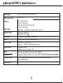
1
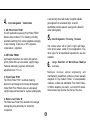
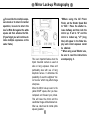
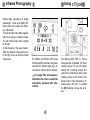
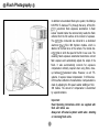
Instructions
Congratulations on your purchase of the Mamiya 645 PRO TL
Mamiya pioneered the 6 x 4.5 film format and introduced the world’s first 645
SLR in 1975. The 645 PRO TL is the latest masterpiece in this series and
Incorporates all the latest mechanical, electronic and optical advances. Its
external appearance, too, has been modernized and its ergonomic design
further enhanced.
We are sure that you will enjoy the many advantages this camera and its
accessories offer and want to particularly mention :
The 645 PRO TL has a built-in self-timer (delayed shutter release) which will
also facilitate time exposures. Attaching special leaf shutter lenses will
automatically set the focal plane shutter to 1/8 sec. Heavy duty gears connect
to the improved Power Drive Grip WG401, This grip also automatically cocks
the leaf shutter lenses and permits remote control.
The AE Prism Finder FE401, specially created for this camera, automates
exposure and shows LED safety signals. 35mm film holders now come with
panoramic adapters. A super fast 300mm f/2.8 APO lens was also designed
for this camera.
We are convinced that your camera will serve you well, because we have
designed it for heavy professional use. However, we ask you to please read all
operating instructions carefully before you put your equipment to work, in
order to ensure proper operation and maximum results
This manual covers the basic
camera. Separate instructions
are supplied with all system
accessories, including lenses,
finders, film holders, etc.
For additional information
please feel free to contact your
authorized Mamiya dealer or
the Mamiya importer in your
country.
Contents
Special Features of the Mamiya 645 PRO TL ....... 3
Names and Functions of Parts .............................. 7
Attaching and Removing Lenses ........................ 10
Attaching and Removing the Roll Film Holders. 11
Attaching and Removing the Viewfinder ............ 12
Removing and Attaching the Film Advance
Crank ...................................................................... 13
Inserting the Battery ............................................. 14
Battery Check ........................................................ 15
Shutter Release Selector ...................................... 16
Shutter Performance Test .................................... 17
Before Film Loading ............................................. 16
Film Loading .......................................................... 19
Advancing the Film to the First Frame.. .............. 21
Shutter Speed Settings. ........................................ 22
Aperture Ring/Stop-down Operation.. ................. 23
Focusing ................................................................ 24
Depth of Field ........................................................ 25
Film Advance and Unloading Exposed Film ...... 26
Using the Self-timer/Delayed Shutter Release.. 27
Time Exposures .................................................... 26
Multiple Exposures ............................................... 26
Mirror Lock-up Photography.. .............................. 29
Infrared Photography.. .......................................... 30
Using a Tripod ....................................................... 30
Flash Photography.. .............................................. 31
Holding the Camera Steady and Securely.. ........ 35
Attaching and Removing the Neck Strap.. .......... 36
Basic Accessories ................................................ 37
System Chart ......................................................... 39
Trouble Shooting .................................................. 40
Mamiya 645 PRO TL Specifications .................... 41
Things to Watch .................................................... 43
Common Sense Camera Care and Practice ....... 44
Special Features of the Mamiya 645 PRO TL
1.
Image Area about 3X larger than 35mm
Format
- Bigger is better -The 6X4.5cm image size is about 3x larger than 35mm
and therefore produces far superior results. It is large
enough to be viewed without magnifier and its aspect
ratio of about 1.25 (long side : short side) matche s the
standard 8 x 10 inch “ideal format”, the most popular in
photography and industrial use. It requires minimum
cropping and gives maximum film utilization. (15 or 30
exposures on 120 or 220 film respectively)
2.
Rugged, Versatile and Reliable Camera
Body
- Built for professional use -Mamiya pioneered the 645 SLR camera system in 1975
to create medium format image quality with 35mm
handling ease. New models have periodically followed
over the years to keep in step with mechanical, optical
and electronic advances
3.
Interchangeable Rollfilm Holder System
-120, 220, 35mm, 35mm Panoramic and Polaroid -Permits quick film change, even in mid-roll. Many fail
safe features prevent accidental exposures or film waste.
4.
Interchangeable
Viewfinders
1. AE Prism Finder FE401
The AE (automatic exposure) Prism Finder FE401
features three modes of TTL metering, including
automatic switching from center-weighted averaging
to spot metering. It also has a +3EV exposure
compensation adjustment.
2. AE Finder FK402
Light weight, Keplerian (non prism) AE aperture
priority finder offers an unreversed, upright image
Features telescoping eyepiece with diopter
adjustment from +5 to -5.
3. Prism Finder PF401
The Prism Finder PF401 is without metering
electronics and designed for manual photography
mode. Both Prism Finders show an unreversed,
upright image and are ideal for eyelevel photography.
4. Waist Level Finder N
The Waist level Finder N is desirable for low angle
photograhpy and particularly for horizontal
composition.
A self erecting hood with built-in magnifier shields
groundglass from all ambient light. A built-in
sportsfinder permits eyelevel viewing and is ideal for
action photography.
5.
Interchangeable Focusing Screens
The camera comes with a Type E, bright, split image,
micro prism screen, useful for most applications. Five
other types, for all specialized requirements, are also
available.
6.
Large Selection of World-Class Mamiya
Lenses
Mamiya’s in-house optical engineering and
manufacturing department produces lenses specially
designed for the medium format, of unsurpassable
resolution, contrast and color fidelity. From 24mm Fisheye
to 500mm telephoto, plus macro, zoom and APO lenses,
these lenses have become the choice of the pros.
7.
Motorized Power Drive Grips
Two accessory motorized drives, interchangeable with
the manual film advance crank, are incorporated into an
ergonomically designed grips for easy, right handed
camera operation.
Model WG 401 requires 6 AA batteries and features
multiple exposure switch, cable release socket, battery
check and continuous shooting. It also can be used with
leaf shutter lenses.
Model WG402, a simplified version, permits only
individual exposures, uses one 6 Volt lithium battery and
is much lighter.
Accessory System
8 . AForBroad
Specialized Applications
A useful accessory system to serve the specialized
needs of the photographer. It includes Auto Bellows and
Auto Extension Rings for close-up and copying work;
Infrared Remote Control for studio and nature
photography; External Battery Case for operating in cold
surroundings; Camera Grips for convenient holding and
more.
<Self-timer>
Self-timer for delayed shutter release. When activated it
will light a red pilot lamp in the front of the camera for
eight seconds and will blink for two seconds before
triggering the shutter.
<Time Exposure>
Time exposures are made by utilizing the Self-timer and
the "B" shutter setting. A new power saving circuit
design switches the battery off and extends is life.
9.
TTL (through-the-lens) Flash Exposure
Automation
The light that hits the film surface during exposure is
reflected to a photoreceptor within the camera body
which automatically adjusts the flash output to the
required level.
10 .
Other Features
<Mirror Lock-up>
After focusing, the mirror can be locked up before
making an exposure. This is convenient when the
camera is used at slow shutter speeds and is mounted
on a tripod for telephotography, copywork, etc.,
since even a very small amount of vibration should
be eliminated.
<Self-timer>
Shutter will be released 10 seconds after shutter
button is pressed.
<Time Exposure>
When making time exposures, the battery circuit is
automatically disconnected, to save battery power.
This is especially useful for astrophotography.
Names and Functions of Parts @
13 Gold Plated Contacts
These contacts interface the AE
Prism Finder with the IS0 dial on
the film holder and the shutter
speeds.
Focusing Screen N
Aperture Ring Coupling
This pin is fitted into the E
Meter Coupler of the l
transmit the aperture dat
AE Prism Finder.
Hot-shoe (X contact)
A cordless flash can be used with
this shoe.
Battery Check Lamp
Focusing Screen Release Pin
When you want to change the
screen, slide this pin to the left
and remove the screen.
Flash Sync Terminal
Flash cord and optional Terminal
Adapter RA401 can be connected
to this terminal.
Shutter Release Selector
Align the white index dot on the
selector collar with the white
square dot in the center for normal
use. When the collar is turned to
the red dot, the release is locked.
To use the Self-timer, set it to e..
Shutter Release Button
left, the contact appears. This
contact is used for connections of
external releases such as a
Mirror
l Never touch the surface of the
mirror
Battery Check Button/
LED displays the present battery
condition.
0
\ tro’
u”it. Coupling Connector for
6- Pin
dedicated TTL flash
automation. (Such as Metz
SCA396)
Finder Coupling Panel (Front)
tl
Finder Coupling Panel (Rear)
/’
S h u t t e r S p e e d Dial L o c k
Release Button
This button is used for unlocking
the Shutter Speed Dial from an
AE position
This contact receives film sensitivity data from the film holder.
Film Holder Mount
Shutter Curtain
Exposures are controlled by
opening and closing the curtain:
a Never touch the surface of this
curtain.
Film Transport GearFilm Holder Mounting Bracket
Multiple Exposure Lever
When this lever is set at "MULTI",
film is not advanced even when
the Film Advance Crank is turned,
thus allowing multiple exposures
on the same film frame.
Distance Scale
The camera to subject distance
can be set or confirmed with this
scale
Lens Alignment Dot
Depth-of-field Scale
Provides a quick reading of depthof-field for various apertures and
distances.
Exposure Meter Coupler
This coupler is engaged with the
Aperture Ring Coupling Pin, transmitting diaphragm information to
the AE Prism
Finder.
Tripod Socket
1/4’ tripod socket. To convert to
a 3/8’ socket, remove the small
screw in the base of the socket.
Then remove the bushing. See
page 32.
@ Attaching and Removing Lenses 0
Removing the Front Body Cap
and Rear Cover
First remove the Front Body Cap in
the direction of the arrow, while pushing the Lens Release Button 8
backwards as indicated by arrow.
Rear Body Protective Cover can be
readily removed by depressing the
part of @ as shown in the illustration.
Attaching the Lens
Removing the Lens.
Line up red Lens Alignment Dot 0
against red camera Alignment Dot $3
and gently insert the lens into the
camera body. Then turn the lens
clock wise, as indicated by arrow,
until it clicks into place. Make sure
that the Aperture Ring Coupler Pin is
engaged with the Exposure Meter
Coupling Pin @I,, which sticks out
under the Mamiya name plate of the
camera.
While pushing lens release button @
backwards, turn lens counterclockwise. (Same procedure as
removing body cap).
Attaching and Removing the Roll Film Holder
Removing the Rear Body Cap
Attaching the Roll Film Holder
Rear Body Protective Cover can be
readily removed by depressing the
part of 0 as shown in the illustration.
* Remove the Roll Film Holder
Cover.
1. While spanning the Roll Film Holder
between your thumb and middle finger, holding it on the rubberized finger rests, carefully align its Film
Holder Mounting Bracket with the
corresponding center clip of the camera body.
*After removing the rear cap, be
careful not to touch the shutter
blind. This can cause breakage of
shutter.
2. While keeping this alignment, press
the upper part of the Roll Film Holder
against the camera body, so that it
clicks into place by engaging the
spring loaded twin camera catch.
Attaching and Removing the Viewfinder
Removing the Roll Film Holder
Attaching the Finder.
Removing the Finder
1. Insert the Dark slide into the slot
marked by White Lines on the side of
the holder.
2. Push the lower one of the Film
Holder Detaching Lock Release
Button @ downward, while simultaneously pushing the Film Holder
Detaching Button @$ inward.
Lift the Upper Cover from the camera
body.
Insert the Attaching Latches of the
finder into the Finder Coupling Panel
@I in the front wall of the body. Press
the finder down until the rear latch
locks securely in place.
Spanning the finder with your fingers, push the button on its right side
marked with a downward pointing
arrow @ @I, downward, while
pushing the other button, on the left
side @ 0, inward.
* If the Dark Slide is not inserted,
the safety lock will prevent the
holder from being removed.
Removing and Attaching the Film Advance Crank
Removing the Crank
Attaching the Crank
Push the lock Lever ‘&> on its bottom
in a forward direction as far as it will
go (see illustration).
With the flat part, having a White
Index Line, on top, line the Crank up
against its mounting plate on the side
of the body and push Film Advance
Crank Lock Lever backward.
You may choose six different crank
starting positions to suit your preference. The orientation of the crank
proper against its base, before it is
attached to the camera, will be maintained when the entire assembly is
locked into place.
0 Inserting the Battery
The camera will not function without a battery
With your fingernail, pull the Battery
Chamber Cover latch, on the bottom
of the camera body, as indicated by
the arrow in the illustration. Lift the
cover off. The camera requires a 6V
alkaline, silver oxide or lithium battery. It is a good idea to wipe the
battery terminals before insertion to
assure proper contact. Observe polarity. Q position is marked in battery
cavity. Insert the G side first at a
steep angle and then push entire
battery into place, making sure that
the lift ribbon wraps around battery.
Close cover by inserting twin-prong
end first and pushing it down.
* Be particularly careful not to let
the lift ribbon cover the c” terminal.
Batterv Check
Press Battery Check Button “B.C.”
8 on lower front of the camera.
Battery Check Lamp @I on top opposite side should light. Bright light indicates good condition. Blinking light
means replace battery. No light
means battery is dead or improperly
inserted.
Important:
1. The sealed, new battery which is
supplied with this camera may have
been subject to storage conditions
which have reduced its service life.
Therefore it is desirable to replace it
with a fresh battery as soon as
possible.
2. Carefully wipe the battery contacts
before inserting into the chamber.
Failure to do so may result in poor
electrical contact and consequent
malfunctioning of the camera.
3. Always remove battery when
camera is not used for a while. Always
carry spare batteries.
4. Battery life differs, depending on
type, age. storage condition, ambient
temperature, frequency Of use etc.
Battery strength will be indicated
by whether the light:
Glows ... Battery stength is
sufficient.
Blinks ... Battery capacity has
dropped below the
allowable level.
(Replace the
battery.)
Does not light .,..... The camera
will not work. (Replace
the battery.)
Shutter Release Selector
When set to the yellow clock symbol
ti’ the self-timer is operative. See
page 27 and 28 for further instructions.
Operating the Shutter Release
Button
1. The Shutter Release Button SJ
For normal operation set the White
Dot of the Shutter Release Selector
(8 against the White Square Dot 0.
When set to the Red Dot 0, the
Release Button is locked.
* Select this mode if the camera
will be idle for a period and to
prevent accidental shutter release.
Also when the Power Drive Grip is
used.
functions in two steps. Gentle pressure will light the metering information display if the AE Prism Finder is
used. Continued pressure will release
the electromagnetic shutter.
2. If the film is not completely advanced, if the Dark Slide is not withdrawn or if the battery is dead, the
shutter will not function, even when
the Shutter Release Button is
pressed. This will also be the case if
the Shutter Speed Dial is set to “A” or
“AEL” when the AE Prism Finder is
not attached.
a3
3. After releasing the shutter, the
Film Advance Crank will automatically unlock and be ready to advance
the film.
Shutter Performance Test
1. Attach the Roll Film Holder to the
camera body.
2. Pull out the Dark Slide and place it
into its Storage Slot.
3. Set the Shutter Speed Dial to any
other position than ‘A”or “AEL”. When
the AE Prism Finder is not mounted
on the camera, the shutter will not
release if the Shutter Speed Dial is in
the “A” or “AEL” position,
the film holder is supplied with a
vinyl tube. When placed in the
take-up compartment it engages
the film sensor and makes the
holder function as if it is loaded
with film. Please remove the tube
4. Set the Multiple Exposure Lever
on the body to the “MULTI” position.
Before Film Loading
Film Speed (ISO) Dial
Memo Clip
r
,I-
!
-I
L
5. Set the Shutter Release Selector
to " 0 " (normal mode), and press the
Shutter Release Button.
6. After the shutter has been released, advance the Film Advance
Crank one complete revolution and
the next frame will be ready.
Film
Speed Index
of film holder
Each film holder has this important
feature. It electronically interfaces the
film holder with the AE Prism Finder,
the focal plane shutter and the lens
diaphragm, for exposure automation.
This eliminates the need of having to
manually reset the meter, every time
you change film holders loaded with
different films. Therefore make it a
routine to always set this dial with the
speed of the loaded film.
IS0
25
The Memo Clip on the back of the
Roll Film Holder Cover accepts the
box top of the film carton and can
also be used for other reminders.
800
1600
3200
50
100
200
400
6 4 0 0
(32)(40) (64)(80) (125)(1601 (X0)(320) (5001(6401(10001(1250) (2ooo)c25oo,(4oao)(sooo)
0
Film Loading
1. While pushing the Back Cover
Lock Release Button 8 downward,
press the Back Cover Opening Button @;:, and the Back Cover will open.
2. While squeezing in on both sides
of the Release Latch CQ, pull the Roll
Film Insert out of the camera body. At
that time, move the empty spool in
the upper part down to the lower
spool compartment
When you load film for the first
time, remove and discard the
protective paper cover which is
attached to the film rails in the
roll film holder.
3. Align the right-hand side of this
empty spool with the lower Spool
Stud ‘8 (convex). Slide the spool into
position making sure that the leftside of the spool is properly held by
the Spool Clip.
4. In the same manner, insert a roll of
film in the upper compartment. At
that time, check that the film leader
paper is set as shown in the photo
above. (The leader paper inside is
facing outward on the pressure plate.
Note that the film direction is wrong if
the leader paper is facing inward.)
5. Pull out some of the leader paper.
Insert the tip of the leader paper into
the slot of the lower Take-up Spool.
6. Gently rotate the take-up spool as
shown in the photo until the start
mark on the leader paper is aligned
with the start mark (a) on the spool
clip.
* Correctly align the start marks
with each other, making sure that
the film feeds properly. When improper feeding occurs, the proper
number of exposures may not be
taken.
* Avoid exposing the film to direct sunlight when inserting or removing film.
@I
* 220 Film Loading Caution
220 films have two types of Start
Mark Lines across the paper
leader. Always use the second one,
a solid line with the legend “Start
Mark for standard cameras”,
located about 14cm (5 1/2”),
behind the first, dotted Mark line.
DO NOT use the dotted line for a
start mark.
Advancing the Film to the First Frame
7. Insert the loaded Roll Film Insert
into the holder, the film roll on top,
while squeezing on both sides of the
Release Latch Cc as shown in
illustration. Make sure that is been
properly seated and is locked in place.
Then close cover by firmly pressing
its top against the Roll Film Holder.
* To close the Back Cover, firmly
press the top of the back cover on
both sides.
1. While spanning the Roll Film Holder
between your thumb and middle
,.
finger holding itit on the rubberized
finger rests, carefully align its Film
Holder Mounting Bracket with the
corresponding center clip of the
camera body.
2. While keeping this alignment, press
the upper part of the Roll Film Holder
against the camera body, so that it
clicks into place by engaging the
spring loaded twin camera catch.
Set the multiple exposure switching
lever A to the white square mark 0
(normal mode).
Shutter Speed Settings
I
/
3. Wind up.
Wind up the crank handle until it
stops. In the film counter window, the
number 1 appears, and the film and
shutter are set.
I
I
How to set the Shutter Speed Dial
1. Set the desired shutter speed
against the white index line (A) on the
shutter speed dial.
2. At the red “A" (for Automatic) and
AEL (for Automatic Lock) settings,
the shutter speed dial is locked
between these two positions. These
settings will only function if an AE
Finder is mounted on the camera. To
release this lock push button (B) while
turning dial.
3. All while numbers are fractional
seconds. (i.e. 30 =1/30 sec).
@
The yellow 2 and 4 are full seconds.
“B” (shutter stays open as long as it
is depressed) is also yellow.
4. Red 60 is 1/60 sec. It is colored red
to remind you that it is the fastest
speed useable with electronic flash.
5. Note: When a Metz Electronic Flash
Unit, together with SCA 396 module,
is attached to the camera, the camera
sets itself automatically to 1/60 sec.,
irrespective of the dial setting.
* When manually selected shutter
speeds are set on the shutter speed
dial, the intermediate shutter
speeds available in the AE
operation are not obtainable.
Aperture Ring/Stop-down Operation
* When the AE Finder is used, be
sure to return the A/M lever to “A”
(Auto), after having checked the
effect of the manually set aperture.
The AE finder measures the
required exposure through the
lens at maximum aperture and will
give false results if lever is left in
“M” position.
Set the desired f/stop on the aperture Ring 6) by aligning the f/number
with the red reference dot SC@ in the
center of the Scale Ring. The Aperture Ring has a click stop for each f/
stop. In-between settings can also
be used.
The effect the set f/stop will have
upon the picture area can be confirmed on the Finder Screen.
Move the AM Lever on the lens so
that “M” becomes visible-the lens
then can be stopped down to the
preselected aperture.
0 Focusing 4B
While looking through the viewfinder,
turn the lens Focusing Ring until the
most important subject part appears
sharp and clear.
Focusing with the Standard Focusing Screen N Type E
r-
1. The camera comes equipped with
a bright, Type E, Rangefinder/Microprism Focusing Screen. It features a
center, split-image rangefinder spot
and the subject is in sharp focus
when the split images combine into
one.
2. The microprism ring around the
split-image center further facilitates
focusing. The microprisms disappear
only when the subject is in sharp
focus.
3. The rest of the ground glass area
can also be used for focusing.
*Interchangeable F o c u s i n g
Screens
There are five additional focusing
screens available for specialized
applications. They are easy to
interchange and come with instructions.
Depth of Field
Reading the Depth of Field Scale
Depth of field is defined as the zone
of sharpness before and behind the
plane of focus. It depends on camera
subject/distance, focal length of lens,
aperture setting and distance the lens
is focused at.
~11 16 22
1
I
In addition to visual observation, the
Depth of Field can be determined by
using the Depth of Field Scale on
each lens. f/stop numbers appear on
both the right and left side of the red
index mark in the center of the scale
ring. Simply read the figures which
appear above the f/stop numbers on
the distance scale of the lens.
For example, with the 80mm f/2.8N
lens focused at 3m and the aperture
set at f/22, the depth of field scale
indicates that the zone of sharp focus
will extend from about 2m to 6m.
Film Advance and Unloading Exposed Film
Film Advance
Unloading Exposed Film
* Move the empty spool from the
top to the lower (take-up)
compartment, ready for loading
the next film roll.
*Never load, unload or handle film
in direct sunlight.
1. Giving the Film Advance Crank
one complete turn, will cock the shutter and mirror and ready the camera
for the next exposure.
2. When the film is completely exposed (15 exposures on 120, 30 on
220 film), the crank stop will disengage. Continue turning until the paper trailer is completely wound onto
the take-up spool. (About five turns
after the last exposure.)
3. Open the Back Cover, and remove
the Roll Film Insert. The Exposure
Counter will return to S (start)
automatically.
4. Pull the Spool Clip on the roll film
insert out to remove the film.
5. Remove the film from the roll film
insert; make sure that the film on the
roll does not loosen, and seal
immediately.
Using the Self-Timer/Delayed Shutter Release
To use the Self-Timer, set the Shutter Release Selector to @ and press
the Shutter Release Button.
The Battery Check Lamp will light for
8 seconds and blink for 2 seconds,
whereupon the shutter will go off.
* After using the self-timer mode,
be sure to return the Shutter Release Selector to the White Square.
(Normal mode.)
-k To override the self-timer, after
having pressed the release, move
the selector back to the white
square.
* The Self-Timer can also be overridden by inserting the Dark Slide
into the Film Holder or setting the
camera Shutter Speed Dial to “B”.
Please note:
If you want to use the self-timer
with the shutter speed dial set at
“A” or “AEL” and there is no AE
Finder attached to the camera, it
will not release the shutter even
though the light goes on for 10
seconds. However, when the dial
is set to manual speeds, the selftimer will function.
Time Exposures
For time exposures set the Shutter
Release Selector to c, the self-timer
mode, and set the Shutter Speed
Dial to "B". Press the shutter release
and both mirror and shutter will stay
open until the shutter release is
pressed again. You may also use a
cable release together with the cable
release adapter. (The battery circuit
will automatically switch off to save
power.)
Multiple Exposures
* "B" can be terminated by shifting the Shutter Release Selector
from 23 or the Shutter Speed Dial
from "B"
Aligning the white dot of the Multiple
Exposure Lever with the yellow
“MULTI” square, disengages the multiple exposure prevention mechanism, and the film will not advance
after an exposure is made and the
Film Advance Crank is turned.
However, the shutter will be recocked,
thus making multiple exposures
possible. In this mode the Exposure
Counter will not advance.
Mirror Lock-up Photography
* To override the multiple exposure mode or to return to normal
operation, be sure to return the
lever’s White Dot against the white
square and then advance the film.
(If you forget you will continue to
make multiple exposures on the
same frame.)
This is an important feature when the
tripod mounted camera is used at
slow or long exposure times and
particularly also with use of long
telephoto lenses. It eliminates the
possibility of even the slightest “mirror bounce” which may affect image
sharpness.
Move the Mirror look-up Lever to the
yellow ”M.UP” square, after you have
composed and focused your picture.
This will raise the mirror and the
viewfinder image will be blacked out.
After use, return lever to normal (white
square) position.
@
*When using the AE Prism
Finder, set the Shutter Speed Dial
to “AEL”. Press the shutter release halfway and then lock the
mirror up. If set to “A” and the
mirror is locked up, “LT” (long
time) will appear in the finder display and correct exposure cannot
be obtained.
* When using a Leaf Shutter Lens,
be sure to read the instructions
accompanying it.
Infrared Photography
Infrared light rays-being of longer
wavelength - focus at a slightly different plane and require the following adjustment:
1. Note the Red Index Mark against
which you read your distance scale.
The red infrared index mark is slightly
to its right.
2. After focusing in the usual manner,
read the distance scale and move it
to the right to line up with the infrared
index mark.
@ Using aTripod @
14 56 8 11 1621
The 300mm and 500mm APO lenses
for Mamiya 645 cameras, being also
corrected for infrared light rays, do
not need an index mark for infrared.
* For proper filter and exposure
information be sure to consult the
instructions enclosed with infrared film.
The Mamiya 645 PRO TL Tripod
Socket accepts a standard 1/4” tripod
mounting screw. For use with tripods
having 3/8” mounting screws, first
unscrew the small black philips head
retaining screw in the center of the
tripod socket. Then remove the 1/4"
bushing with a thin coin. To re-install
the 1/4 bushing, reverse the process.
Flash Photography
In addition to its standard flash sync system, the Mamiya
645 PRO TL features TTL (through the lens), off the film
(OTF), electronic flash exposure automation. A flash
sensor located inside the camera body reads the flash
reflected from the film surface at the moment of exposure.
The .sensw is connected via coilcords to a dedicated
electronic Metz SCA 396 thyristor module, which is
attached to the flash shoe of the camera. The module has
an IS0 dial on which the speed of the film in use is set. The
resulting flash exposure automation determines correct
flash exposure and automatically adjusts the output of the
flash. It also automatically corrects for exposure
compensation ordinarily required when using filters, closeup bellows or extension tubes. However, as all TTL
systems, it requires manual compensation for differences
in film surface reflection characteristics. Compensation is
made by adjusting the film speed selector setting an SCA
396 module. The amount of compensation is determined
by experimentation.
Important:
Read Operating Instructions which are supplied with
flash unit before use.
Always turn off camera’s power switch when attaching
or removing flash units.
Attaching Metz Flash Units
Metz flash 60CT-4/45CL-4
Various optional accessories are
needed to attach different Metz Flash
Units to the Mamiya 645 TL
Metz shoe mount flash type
Metz flash 50MZ-5
This table shows accessories required with various Metz Flash Uunits
I
SCA396 adapter IF?
Metz Flash Units
SCA300 adapter 3
Bracket AD401 E’
Double shoe adapter
AD402 0‘
--.-.-__~-_---.- -_----.__---. _--- _-.-.~---~_-~- -. _.- Shoe
mount
flash
“,“;$;
flash
60CT-4
50MZ-5
45CL-4
40MZ-3
40MZ-2
32MZ-3
32Z-2
m
Yes
No
No
No
Yes
Yes
No
Yes
Yes
No
Yes
No
No
No
_---_---~.-No
No
Yes
Yes
No
No
No
Yes
No
No
No
-
TTL Flash Photography with Metz Flash Units
0
0
1. Attach a Metz flash unit which
features TTL function to the camera.
Attach the SCA396 module to the
camera’s flash shoe. Connect the
module’s coiled cables to the camera
and the flash unit.
Set the film speed dial on the SCA396
module to the IS0 rating for the film
in use. The range of IS0 is 25 to
1250.
2. Move the flash unit’s power switch
to ON and the mode selector to TTL.
3. Turn the camera’s shutter release
selector switch to ON. When the
charge cycle is completed you will
see an illuminated green 5 readylight
in the middle of the right side of the
finder. When the SCA396 module is
connected, the camera’s focal plane
shutter will automatically set at 1/60
sec, and ignore the settings on the
shutter speed dial between 1/60 to
1/1000, including A and AEL. Slower
shutter speed settings, however,
(1/30 to 4 sec.) are not affected and
will allow flash synchronization.
4. Set lens to the desired f/stop and
shoot. After the exposure is made,
the illuminated green f blinks,
confirming proper flash exposure. If
the illuminated green f does not blink
after exposure, it is possible that
aperture selected is not within the
exposure/distance range of the flash.
In this case, select a wider aperture
setting. When using flash at
maximum distance, which requires
the full power of theflash unit, recyling
time will be longer. Wait for the
readylight to go on before firing the
next frame. Exposure Compensation
with TTL Flash Automation.
Because TTL Flash automation reads
the light reflecting off the subject,
exposure may require manual
adjusment in cases where subject
and background are predominantly
white or black (e.g. bride in white
dress against white background;
bridegroom in tuxedo against dark
background.) In these instances, the
resulting TrL exposure will either be
under-exposed or over-exposed. For
such situations, adjustment of about
1 to 1 l/2 f/stops, plus or minus, may
be requiredthroughexperimentation.
Alternatively, a hand held incident
flash meter reading will show proper
exposure in these cases.
Photography with Non-TTL Flash Units
<Caution>
When using the Hot-shoe,
be sure to put an appropriate
Safety Cover over the X-sync
terminal so that you won’t
receive a high voltage
electric shock if the terminal
is accidentally touched. (A
Safety Cover is put on the Xsync terminal when the
camera leaves the factory.)
1. When using an electronic flash,
plug the synchronization cord into
the Sync Teminal and set the Shutter
Speed Dial to 1/60 sec. or slower.
* The Mamiya 645 PRO has an Xsync terminal.
Attach a shoe-mount flash to the hotshoe of the camera or the Left Hand
Grip GL401 (optional).
Flash synchronization Chart
* Do not use a flash unit
specifically dedicated for another
camera. It may damage your 645
PRO.
* If you use a flash unit whose
flash duration is slower than 1/
1000 sec., set the shutter speed
dial to 1/30 sec. or slower.
@ Holding the Camera Steady and Securely h
Eye-level Operation
Hold the camera as shown in the
illustration, with its base resting on
your left hand, the right hand supporting it from the side and top. Press
both elbows against your body and
activate the shutter release with a
smooth, steady pressure.
Waist Level Operation
For waist level operation, it is deslrable to have the Neck Strap attached
and adjusted for your size. During
exposure keep it taut and press the
camera firmly against your body.
* Handholding the camera is even
easier using the Power Drive Grip
WG401 or Left Hand Grip GL401.
Attaching and Removing the Neck Strap
Attaching the Strap to the Camera
1. While pushing down, pull out the
Neck Strap Fastener @ of the attaching clip.
2. Place the hole of the strap fastener
@I over the Neck Strap on the camera body as illustrated, and pull until
it clicks and locks into place.
With your fingers, pull the Neck Stra P
Fastener @I of the attaching clip upward and push part @I in the direction
of the arrow. The strap can now be
removed.
* When attaching the Strap to the
Neck Strap Lug on the side of the
camera with the Film Advance
Crank, insert the neck strap fastener @ into the lower part of the
double slot.
Basic Accessories
The AE Prism Finder FE401
The Mamiya AE (Automatic Exposure) Prism Finder
FE401 pentaprism guarantees a true, upright image and
features built-in electronic shutter control which ensures
aperture-priority, TTL automatic exposure metering while
in the A or AEL mode.
<3-Way Metering System>
The FE401 comes with three metering modes: average
metering (AV), spot metering (SP). and AV-SP metering
capable of automatically selecting AV or SP according to
subject conditions.
The LED display in the viewfinder indicates correct
exposure.
If you forget to extract the Dark Slide when the finder is
being used with the 645 PRO TL, an LED will flash a
warning.
Power Drive Grip WG401
The motorized film transport mechanism is placed in an
ergonomically designed handgrip for speedy (2 f.p.s)
and continuous shooting. Features include cable release
socket, shutter release lock, multi-exposure switch, first
frame advance, battery check, and power connector
socket for leaf shutter lenses. Uses 6 AA 1.5 V. batteries.
AE Reflex Finder FK402
This aperture priority, Keplerian type, automatic (AE)
reflex finder features TTL auto or manual exposure with
center weighted averaging. It offers upright, eyelevel
viewing with unreversed image.
Exposure is indicated by red and green LEDs.. A built-in
adjustable diopter eyepiece can be set from +/-5 for
viewing convenience without eyeglasses.
Power Drive Grip WG 402
This simplified, compact, lightweight grip uses one 6 V.
lithium battery. It has a shutter release with lock and
offers single frame exposure mode.
/ Roll Film Holders
120 Roll Film Holder HA401
220 Roll Film Holder HE401
135 Roll Film Holder HC401
(with Panoramic Adapter)
Polaroid Land Pack Film Holder HP401
Metz TTL Flash Unit
Shoe Mount
60CT-4
etc.
Handle Mount
40MZ-3
etc.
Flash Bracket AD401
I
Interchangeable Lenses
Wide-angle Lenses
: 35mm f/3.5N. 45mm f/2.8N,
Telephoto Lenses
: 150mm f/3.5N, A150mm
55mm f/2.8N
f/2.8, 210mm f / 4 N
ULD300mmf/5.6N,A200mm
f/2.8 APO, A300mm
f/2.8APO, A500mm
f/4.5 APO/500mm f/5.6
Standard Lenses
: 80mm f/1..9N, 80mm f/2.8N,
Zoom Lenses
: Zoom 55 - 110mm f/4.5N,
Zoom ULD105 1 210mm
f/4.5
Special Effect Lenses : Fish-eye ULD24mmf/4 Shift
50mm f/4. Macro 80mm f/4N
Macro 120mm f/4M
Leaf Shutter Lenses
: A55mmf/2.8N/L,A80mm
f/2.8N/L, A150mm f/3.8N/L
Tele-Converter
: 2 x Tele-Converter
System Chart
PnSm FiIlder FP40,
AE Fl”&l FK402
wa,st Level Fin&i N
Trouble Shooting
* If the camera should fail to function properly,
please check the following:
1. The Shutter Release Button cannot be depressed.
Push the Battery Check Button.
If the lamp does not light, check:
Is a Battery in the camera?
If yes, is it correctly inserted? (Polarity)
Is it dead?
If the lamp does light, check:
Has the Film Holder Dark Slide been pulled?
Is the Shutter Release Selector in the locked
(Red Dot) position?
If so, move it to the White Square and try again.
Is the Shutter Speed Dial in the “A” or “AEL”
position?
If so, turn to other setting and try again.
2. The finder is black or very dark.
Has the Lens Cap been removed?
Is the Mirror-up Lever in the “M.UP” position?
If so, turn the lever to the White Square.
Is the “AM” setting on the lens at “M” (Depth of
Field Preview)?
If so, move it to “A”.
3. The Roll Film Holder cannot be removed from the
camera body.
Insert the Dark Slide.
4. The developed film has fewer exposures than Specified.
Most likely the Start Mark had not been aligned
properly when the film was loaded. (See load
ing instructions page 20)
5. The Film Advance Crank continues to turn and does
not stop.
Was the Roll Film Insert placed in the Roll Film
Holder?
Was the empty fim spool left in the upper
compartment?
Mamiya 645 PRO TL Specifications
Camera type
6X4.5cm electronically focal-plane shutter SLR
Actual negative site
56mm X41.5mm
Film type
120 roll
220 roll
Polaroid
135 roll
film (15 exposures)
film (30 exposures)
pack film (Polaroid 100, 600 series)
film in film cartridge
-
Film loading
Daylight loading
Standard lenses
Mamiya-Sekor C 80mm f/2.8N
Mamiya-Sekor C 80mm f/1.9N
interchangeable film holders with film speed dial
Lens mount
M645 bayonet mount (applicable to all M645 lenses)
Shutter
Moving coil, electronic controlled focal-plane shutter
Shutter speed
(Manual) 4 sec. -1/1000 sec., B (T)
(Auto) 8 sec. - 1/1000 sec. (When the AE Finder is used.)
Shutter release
Electromagnetic release.
Selectable release lock or self-timer mode.
Mirror
Instant return, front coated mirror, with mirror lock-up capability.
Viewfinder
Interchangeable (Waist Level Finder N, Prism Finder FP401, AE Prism Finder FE401 and AE Finder FK402)
Focusing screen
Standard: Rangefinder Spot/Microprism with Fresnel Lens,accessory screens available.
(Same as the M645 Super)
Field of view
94%
.
Things to Watch
* When using the AE Prism Finder FE401
When using this finder it is imperative that the Film
Speed Dial on the Roll Film Holder is properly set for
the IS0 number of the loaded film, as it interfaces with
this finder. If not done, wrong exposures may result.
* When the mirror is locked in the up position.
The Focal Plane Shutter Curtain may be damaged if
the camera faces strong light sources, especially the
sun. Return mirror to normal position or use lens cap
to prevent such damage.
Common Sense Camera Care and Practice
Your Mamiya 645 PRO TL is a precision mechanicaloptical-electronic instrument, built for heavy and reliable
professional use. It will reward you with a long service life
if properly treated and maintained. Please observe these
common sense rules:
* Read instructions before using camera.
* Protect camera against shocks and falls. Use
neckstrap supplied with it, whenever possible.
* Protect camera against rain and moisture. If it gets
wet, wipe it with a soft, clean cloth.
* Do not touch lens or mirror surfaces. To remove dust
use air blower or lens tissue. To remove fingerprints
use lens tissue and lens cleaning fluid if necessary.
* Do not touch gold plated contacts on camera body,
lenses, rollfilm holders and AE Finders. If necessary.
wipe them with a clean, dry cloth.
* Operate the film advance lever with even, measured
strokes, to assure proper spacing.
* Always test your equipment before going on important
assignments.
+
Do not store camera at temperatures exceeding 40%
(lOYF)and-lO’C(15”F)andprotect it against humid
or sea air environment.
* Periodically exercise your camera and lenses by
making blind exposures at various shutter speeds.
Also move the diaphragm ring and focusing mounts of
all lenses repeatedly.
Battery Advice :
* The battery supplied with the camera by the factory
may have been subject to storage conditions which
have reduced its service life. Check it before use and
always carry spare batteries.
Be sure to wipe battery contacts before inserting it, in
order to insure proper contact.
Be sure to observe proper polarity. (Match +pole of
battery with +mark in battery chamber.)
Battery life varies, depending on make, frequency of
use, age, storage condition and ambient temperature.
(Place battery in External Battery Case accessory
which you wear inside your clothing, when
photographing in cold climates)
* Always remove the battery when camera is not used
for longer than a few weeks and store it in a cool, dry
place.
Storage
* When storing camera :
Turn shutter release selector dial to the red dot. (Off
position)
Leave shutter and mirror in uncocked position.
The same applies to leaf shutter lenses.
@
Special Advice To Professional Photographers
Your Mamiya 645 PRO TL is designed for heavy
professional use and will give you a long service life if
properly maintained. Your camera and lenses have
many moving parts which require periodic lubrication. Its
electronic components, too, are subject to wear and tear
and are affected by ambient conditions like dust, sand,
sea air, heat and moisture.
If cameras had odometers like automobiles. it would be
easier to specify servicing schedules. May we suggest
that if you shoot thousands of film rolls per year, you send
your equipment annually for servicing by the Mamiya
distributor in your country