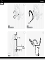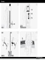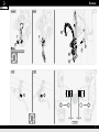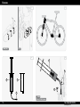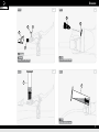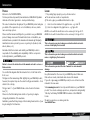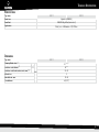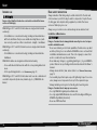
1
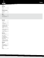
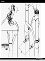
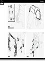
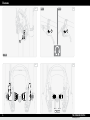
Owner's manual HS 33 · HS 11 THE PASSION PEOPLE www.magura.com Contents Diagrams Introduction Preface................................12 Legend................................12 Technical Specifications Specifications.....................13 Dimensions.........................13 English Safety Intended use.......................14 Basic safety instructions.....14 . Installation Fit the brake........................16 General................................. 16 Installing brake lever............ 16 Installing brake cylinders...... 17 Adjusting brake cylinders..... 17 Adjusting the quick release skewer.................................. 18 Installing the brake booster.. 18 Shortening brake hose......... 18 Adjusting the brake levers.... 18 On the move Prior to your first ride..........19 Before each ride..................19 Opening the brake for . dis-/mounting the wheel....19 Applying the brake..............19 Setting the pressure point/ compensating for pad wear.19 Maintenance Regular................................20 Changing brake shoes.........21 Bleeding and filling brake....21 Rules Warranty.............................23 3 Diagrams TD 1 E G F 4 THE PASSION PEOPLE www.magura.com Diagrams A1 A2 B1 B2 English 1 1 2 T25 4 N·m (35 lbf·in) max. 2 4 3 4 1 5 T25 T25 5 Diagrams B3 HS 11 B4 HS 33 6 6 1 T25 B5 6 B6 THE PASSION PEOPLE www.magura.com Diagrams B7 C1 3 English 4 4 4 T25 6 N·m (53 lbf·in) max. T25 6 N·m (53 lbf·in) max. D1 D2 1 ~12 mm 2 8 mm 7 Diagrams D3 D4 1 4 5 8 mm 4 N·m (35 lbf·in) max. ~5 mm HS 11 E1 HS 33 F1 1 1 1 T25 8 THE PASSION PEOPLE www.magura.com Diagrams CLOSED G1 OPEN English 5 1 7 T25 4,5 N·m (40 lbf·in) max. 6 4 2 3 1 HS 11 H1 HS 33 1 1 9 Diagrams J1 1 mm min. ! K1 CLIC ! L1 L3 2 4 3 2 5 1 8 mm 4 N·m (35 lbf·in) max. 10 THE PASSION PEOPLE www.magura.com Diagrams L4 HS 11 L5 HS 33 10 8 11 9 English 6 7 T25 0,5 N·m (4 lbf·in) max. 8 mm 4 N·m (35 lbf·in) max. L6 HS 11 L7 HS 33 3 3 T25 0,5 N·m (4 lbf·in) max. 11 Introduction Introduction Preface Welcome to the PASSION PEOPLE, You have purchased a powerful, low-maintenance MAGURA HS hydraulic rim brake of the latest generation – developed in Germany. This owner's manual is an integral part of your MAGURA product and gives you details of the required tools, correct installation, safe use, maintenance and setup options. Please read this manual carefully before you install or use your MAGURA product. Always observe and follow all instructions on installation, use and maintenance provided in this manual and in manuals by third-party manufacturers whose products you use on your bicycle (headset, stem, wheels, brakes, etc.). Remember that the mechanic who installs your MAGURA product is responsible for the suitability and compatibility of all the components technically linked to your MAGURA product. Failure to observe the instructions in this manual can lead to serious or fatal accidents. You can find the diagrams that this manual refers to in the folder in the front cover. The figures in this manual may differ slightly from your MAGURA product, however, the required steps are the same for all types and variants – if not stated to the contrary. The type name (1) of your MAGURA brake can be found on the brake lever [TD]. Please note that the braking characteristics of your bicycle may be changed by installation of the new brake. . Familiarize yourself with any changes in the braking characteristics of your bicycle during the first few rides. 12 Legend )) The pointing finger prompts you to perform an action. ÎÎ The arrow shows results or requirements. LLThis notice gives you additional information or tips. refers to an item number in the graphic area – e. g. item ô. [B2] refers to a diagram in the graphic area – e. g. figure B2. (3) HS 11: A notice with this identification refers exclusively to the type HS 11. HS 33: A notice with this identification refers exclusively to the type HS 33. This notice warns you about a dangerous situation which can lead to serious or fatal injury if not avoided. This notice warns you about a dangerous situation which can lead to minor or slight injury if not avoided. This notice warns you about the risk of material or environmental damage. Keep this manual for other users of your MAGURA product. Make sure that each user reads, understands and observes this manual. If you sell or give away your MAGURA product, be sure to hand over this manual to the new owner. Visit www.magura.com for more tips and information on your MAGURA product. You can also exchange experiences, ask questions and generally “talk shop” with many PASSION PEOPLE members on the MAGURA Forum. We wish you great success and a great ride Your MAGURA Team THE PASSION PEOPLE www.magura.com Specifications HS 11 Type name HS 33 hydraulic (MAGURA) MAGURA Royal Blood (mineral oil) Street, tour • AllMountain • XC, XC Race Brake lever Brake fluid Applications English Technical Specifications Technical Specifications Dimensions HS 11 Type name Clamping Ø brake lever (L7) Cantilever socket distance (F) Cantilever socket brake track area min.–max. (G) Ø brake hose Rim width min.–max. Tire width max. [TD] mm HS 33 22 +0.3/-0.1 80 ± 2.0 22–32 5 18–28 64 (2.5") 13 Safety Safety Intended use Any use other than the intended use can lead to accidents that cause serious or fatal injury. MAGURA type HS 11 and HS 33 rim brakes are designed and intended exclusively –– for installation on conventional touring, trekking and mountain bikes with forks and frames that possess suitable mounting fixtures (cantilever socket), as well as on their conventional – straight – handlebars. MAGURA type HS 11 and HS 33 brake levers are designed and intended exclusively –– for installation on conventional touring, trekking and mountain bike handlebars. MAGURA rim brakes are designed and intended exclusively –– for use with wheels that have rims with the corresponding brake track areas. –– for the specified application – see Specifications, page 13. MAGURA type HS 11 and HS 33 rim brakes must never be combined and used with components (brake lever, brake body, etc.) of MAGURA disc brakes! Basic safety instructions Always remember that riding a bicycle entails risk both for the rider and other road users, and for the bicycle and its components. Despite the use of safety gear and complete safety equipment, accidents that cause serious or fatal injury can occur. Always use your common sense and avoid any unreasonable actions! Installation & Maintenance Danger of accident due to damaged brake caused by incorrect or impermissible installation work. –– Never overestimate your technical capabilities. Commission a specialist workshop for bicycles or an authorized MAGURA service centre with all installation and maintenance work. This is the only way to ensure that work is conducted in a professional manner. –– Never make any changes (e. g. grinding/painting etc.) to your MAGURA product that are not specifically permitted and described in the Owner's manual. –– Always observe all min./max. values stated – see Technical Specifications, page 13. –– For assembly steps that require a specific tightening torque for a screw union, always use a torque wrench set up for the required torque. –– Always maintain your bicycle in technically perfect working order. Danger of accident due to improper accessories. –– Use only MAGURA original parts and lubricants. –– Use only original MAGURA brake shoes and for bleeding and filling use MAGURA Royal Blood (mineral oil). –– Never use DOT brake fluid. 14 THE PASSION PEOPLE www.magura.com Safety On the Road Danger of accident due to component failure. Danger of accident due to improper behaviour or improper equipment during riding. –– Before each ride, make sure that the quick release or screw system on –– Always match your speed to the current road and weather conditions.. your wheels is fitted correctly and that your wheels will not work loose. –– Before each trip, make sure your wheels move freely and do not contact the brake pads at any point. –– Before each ride, make sure that the handlebar and stem are correctly fitted and will not twist. –– Before each trip, make sure that both brakes are closed – see Opening the brake for dis-/mounting the wheel, page 19. –– Before each trip, make sure that your brakes operate correctly – the pressure point must be clearly perceptible and does not change when the brake lever is pulled, the brake pads contact the brake track area completely without contacting the tires. –– Before each trip, make sure that your brakes are not damaged in any way, including with the brake lever pulled (e. g. traces of oil, cracks, etc.). –– Before each trip, make sure that the brake track area of your wheels and the brake pads have not reached their wear limits and are free from lubricating substances (oil, grease, silicone, wax, etc.). –– After each crash, check your brake for damage and make sure it operates correctly. –– Never use your brake if damage (e. g. traces of oil, cracks, etc.) is v isible, you can hear unusual noises or if you have any doubts about its integrity. In this case, have your brake checked in a specialist bicycle workshop or directly by MAGURA Service. Transport & Storage Particularly in wet conditions your braking distance will be significantly increased – always ride cautiously and be ready to brake. –– Always use the front and rear wheel brakes simultaneously. –– Always observe the traffic regulations in the country where you are riding (lighting, reflectors, etc.). –– When riding, always wear a high quality (e.g. ANSI certified), undamaged cycling helmet and clothing that fits snugly but does not impair your actions. –– Only ride your bicycle if you are in good physical condition and your bicycle and all of its components are in perfect working order. Danger of accident due to damaged components. –– Make sure that brake hoses cannot be kinked when you pack your bicycle. –– Do not store your MAGURA brake at ambient temperatures below -15 °C (5 °F) and above 55 °C (131 °F). LLIt is not necessary to drain your MAGURA brake before transporting it by air. Protection of the environment Dispose of used lubricants and oil correctly and in accordance with the legal requirements – never discard them in the sewage system or in the ground. 15 Installation Installation Fit the brake General LLThe following assembly steps always refer to the front wheel brake, but they are identical for the rear wheel brake unless otherwise specified. )) Make sure that the dimensions of the handlebar (clamping diameter of brake lever), cantilever sockets and wheels (brake track areas) fit your brake – see Technical Specifications, page 13. LLA thin wire may be helpful for inserting the brake hose through the bicycle frame. . Run it in the opposite direction through the outlet to the inlet of the frame and fix it to the end of the brake hose with adhesive tape. Do not insert the wire into the brake hose – you will lose oil! . Carefully pulling with the wire and pushing the brake hose at the same time will make it easier to find the outlet. LLBefore installing your brake decide which brake lever (right or left) you want to allocate to your front wheel or rear wheel. Danger of accident due to restricted or blocked steering movement because brake hose is too short or too long. LLWhen installing the brake hose for the rear wheel brake use the practi- –– Make sure that there is full steering movement in both directions. –– Keep the length of the brake hose as short as possible and as long as LLInstallation and setting of the brake cylinders can be made significantly necessary. Oil loss. The brake hose may have to be disconnected from the brake cylinder for the following steps. –– Do not actuate the brake lever if the brake hose is disconnected. –– Handle the open brake hose carefully – do not shake it, knock it or hit it. –– Have clean, absorbent and lint-free cloths ready – wipe any leaking oil away immediately. Unusable brake hose – because it is too short. –– Before shortening the brake hose make sure that the handlebar and stem are in their final position and do not need to be raised, extended or adjusted in any way. –– If required, allow a little longer at first – you can always shorten it a bit more but you can't extend it! 16 cal MAGURA hose holder – available in different models. easier if the corresponding wheel is mounted in the frame or fork – preferably without a tire fitted. Installing brake lever Important – see General, page 16! )) Push the brake lever onto the handlebar. ÎÎ The arrows on the clamp point upwards! [A1] )) First tighten the upper clamping screw (1), then the lower one (2) with a tightening torque of max. 4 Nm (35 lbf·in). clamping screw is in contact at the top, there is a gap at the bottom! [A2] LLThe brake lever can be rotated by hand when forced. It is advantageous if the brake lever can rotate in the event of a fall. This reduces the danger of irreparable damage to the handlebar. ÎÎ The THE PASSION PEOPLE www.magura.com Installation Adjusting brake cylinders )) Install the wheel into the dropouts as far as it will go – preferably with- out tires. )) Make sure that the rim is located exactly in the middle between the fork blades or seat stays of the rear triangle – centre the wheel if necessary. Restricted adjustment capability. )) Make sure that the pressure point adjusting screws (TPA) (6) are unscrewed to the stop (-) [B4]. ÎÎ Brake shoes are fully advanced. Push the brake cylinders inwards until the brake pads are in full, flat )) contact with the brake track area. [B5] )) Move the adapter up or down if necessary until the top edges of the brake pads are 1–2 mm below the edge of the rim. ÎÎ Brake pads are in full, flat contact with the brake track area. ÎÎ Brake pads are aligned exactly parallel with the rim. ÎÎ Brake pads cannot come into contact with the tires. ÎÎ Adapters are at the same height. )) Pull the brake lever carefully. ÎÎ Brake shoes retract. ÎÎ Brake cylinders are pushed outwards. )) Carefully pull the brake lever and release until a gap of 1–1.5 mm is produced on one side between the brake pad and brake track area. [B6] )) Then, on this side: tighten the adapter screw (4) and socket screw (3) to a tightening torque of max. 6 N·m (53 lbf·in) [B7] or set the quick release skewer to the definitive pressure – see Adjusting the quick release skewer, page 18. )) Carefully pull the brake lever and release until a gap of 1–1.5 mm is also produced on the other side between the brake pad and brake track area. [B6] )) Then, on this side: tighten the adapter screw (4) and socket screw (3) to a tightening torque of max. 6 N·m (53 lbf·in) [B7] or set the quick release skewer to the definitive pressure – see Adjusting the quick release skewer, page 18. The exclusive purpose of the pressure point adjusting screw (TPA) is to compensate for brake pad wear. Do not use the TPA for the basic setting of the brake cylinders – the brake shoes must be fully advanced. Otherwise there might not be sufficient adjustment travel available later on. 17 English Installing brake cylinders Important – see General, page 16! )) Screw the quick release screw (1) into the right cantilever socket (as seen from above) – by 10–12 turns at first [B1]. )) Push the mounting plate onto the cantilever socket. [B1] ÎÎ The spacers (2) are only required if the mounting plate or adapter are in contact with the fork – max. 1 shim per cantilever socket, flattened side uppermost! ÎÎ The lettering "EVO2" must be legible from the front (as seen from above). )) Place the left brake cylinder (2 connecting lines) on the left cantilever socket (as seen from above) and mounting plate – secure with a washer and socket screw (3) [B2]. )) Screw in the adapter screw (4) and socket screw (3) until the brake cylinder and adapter can just still be moved. )) Place the right brake cylinder with open quick release skewer (5) (OPEN) onto the right cantilever socket/quick release screw and mounting plate – set the quick release lever to the up position (CLOSED) [B3]. )) Screw in the adapter screw (4) and quick release screw (1) until the brake cylinder and adapter can just still be moved. Installation Adjusting the quick release skewer )) Operate the quick release lever – open/close. LLIf the quick release lever can be closed too easily, the quick release screw (1) must be adjusted [G1]: )) Move the quick release lever up (CLOSED). )) Screw in the quick release screw by ¼ turn clockwise. )) Operate the quick release lever – open/close. )) Repeat the procedure if necessary. Installing the brake booster )) Unscrew the right adapter screw (4) (as seen from above). )) Push the brake booster onto the left adapter screw. )) Secure the brake booster with the adapter screw (4) and washer. )) Tighten the right adapter screw (4) with a tightening torque of max. 6 Nm (53 lbf·in) [C1]. Shortening brake hose Important – see General, page 16! )) Push the double hose cover (1) upwards [D1]. )) Cut off the brake hose approx. 12 mm before the end of the hose – use a MAGURA hose cutter if required. )) Twist the barbed fitting (2) out of the brake cylinder with the remains of the hose. ÎÎ The cut-off barbed fitting cannot be reused! )) Hold the end of the brake hose to the brake cylinder [D3]. )) Place the sleeve nut (4) and olive (5) on the brake hose [D4]. )) Insert the brake hose into the brake cylinder to the stop and hold in position. )) Screw the sleeve nut (1) into the brake cylinder and tighten to a tightening torque of 4 N·m (35 lbf·in) [B1]. )) Remove any oil residues thoroughly. )) Pull and hold brake lever. )) Make sure that all connections are tight. )) Push the hose cover (1) downwards. Adjusting the brake levers LLYou can adjust the position (grip width) of the brake levers of your MAGURA HS according to your requirements. [E1] This adjustment does not have any effect on the pressure point of the brake! )) Screw the adjusting screw (1) out ( -). ÎÎ Brake lever moves closer to the handlebar. )) Screw the adjusting screw in (+). ÎÎ Brake lever moves further away from the handlebar. ÎÎ All installation work is complete – the brake is ready for use. Unusable brake hose – because it is too short. –– Calculate the insertion depth (~5 mm) of the brake hose in the brake cylinder [D3]. )) Mark the cut on the brake hose. )) Place the brake hose on a solid surface (wood, plastic, etc.) and cut at right angles with a sharp blade – if required use the MAGURA hose cutter. 18 THE PASSION PEOPLE www.magura.com LLTake some time to familiarize yourself with your new MAGURA brake – preferably away from traffic. Prior to your first ride )) Thoroughly degrease the brake track area of the rims and brake pads using brake cleaner or spirits. LLNew brake pads develop their final braking force during the running-in phase. Danger of accident caused by ill-considered operation of the brake system. –– Make yourself familiar with the arrangement of the brake levers. As a rule, the brake lever for the front wheel brake is fitted on the left side – have the arrangement changed if required. –– Make yourself familiar with the higher braking action of MAGURA HS away from road traffic. Before each ride Danger of accident caused by brake failure. –– Make sure that the quick release skewers of both brakes are closed (CLOSED) [G1] – see Applying the brake, page 19. –– Pull and hold the brake lever and check:. that no oil is leaking from any part of the brake system.. Brake pads are in full contact with the brake track area (1) [F1]. Pressure point is clearly noticeable and does not change. –– Make sure that the rims and the brake pads are intact and free from grease / oil. Danger of accident by bursting tires. –– Make sure that the brake pads cannot contact the tires. Opening the brake for dis-/mounting the wheel )) Move quick release lever (1) down (OPEN) [G1]. )) Remove adapter (2) with brake cylinder (3), quick release skewer (4) and brake booster (5), if fitted, from cantilever socket (6) and mounting plate (7). ÎÎ The wheel can be mounted or dismounted. Applying the brake English On the move On the move )) Push adapter (2) with brake cylinder (3), quick release skewer (4) and brake booster (5), if fitted, onto cantilever socket (6) and mounting plate (7) [G1]. )) Make sure that all components are correctly connected. )) Move quick release lever (1) up (CLOSED). LLIf the quick release lever can be closed too easily, the quick release screw (1) must be adjusted [G1]: )) Move quick release lever down (OPEN). )) Screw in the quick release screw by ¼ turn clockwise. )) Move the quick release lever up (CLOSED). )) Repeat the procedure if necessary. ÎÎ The brake is ready for use. Setting the pressure point/compensating for pad wear )) Screw the adjusting screw (TPA) (1) in (+) (1 turn) [H1]. ÎÎ Brake pads move closer to the brake track area (approx. 0.5 mm). point on the brake lever acts at an earlier point. ÎÎ Pressure LLThe MAGURA brake pads should be regarded as worn when the depth of the indentations is less than 1 mm. [ J1] )) If the brake shoes have damaged or worn brake pads, replace them with new ones. 19 Maintenance Maintenance Regular LLHow frequently you need to maintain your MAGURA product depends on how often you use it, but also on weather conditions.. Perform the following maintenance steps more frequently if you use your bicycle in extreme conditions (rain, dirt, high mileage, etc.).. If you are a frequent user, also consider the fact that this exposes your MAGURA product to more wear and thus requires more frequent maintenance intervals and checks. Corrosion and material damage due to water penetration. –– Never use a pressure or steam cleaner to clean your bicycle – the seals on your bicycle components are not built to withstand this pressure. –– You should even exercise care if you use a water hose. Never point the water jet directly at seal areas [K1]. )) Make sure that the brake responds immediately when the brake lever is pulled. . Bleed the brake if necessary. – see Bleeding and filling brake, page 21. )) Make sure that the pressure point is clearly defined – not spongy – and does not remain constant. . Bleed the brake if necessary. – see Bleeding and filling brake, page 21. Make sure that the brake pads are in full contact with the brake track )) area (1) and do not contact the tires [F1]. )) At regular intervals, check and if necessary tighten the screws on the brake lever (A1), cantilever socket (3) and adapter (4) [B7]. )) At regular intervals, check the clamping of the quick release lever – see Applying the brake, page 19. )) Clean the brake and brake track areas with water, detergent and a brush. )) Clean brake pads and brake track areas on the wheels with suitable degreasers (e.g. brake cleaner, white spirit, etc.). )) Make sure that the brake pads are free from foreign material (stones, glass shards, etc.). . Remove any materials. . If the brake shoes have damaged or worn brake pads, replace them with new ones – see Changing brake shoes, page 21. LLThe MAGURA brake pads should be regarded as worn when the depth of the indentations is less than 1 mm. [ J1] )) Make sure that the brake track areas on your wheels have not reached their wear limits. Replace the rims with new ones if required. 20 THE PASSION PEOPLE www.magura.com Maintenance Changing brake shoes Bleeding and filling brake LLEBT (Easy Bleed Technology) makes it easy to bleed the brake. –– Use only original MAGURA brake shoes appropriate for your rim type. LLThere are 4 different original MAGURA brake shoe blends:. Black – Standard for uncoated aluminium rims. Red – High-grip blend for uncoated aluminium rims. Grey – Standard for anodised /coated aluminium rims. Green – High-grip for anodised /coated aluminium rims )) Screw the adjusting screw (TPA) (6) on the corresponding brake lever out as far as the stop ( -) [B4]. )) Open the brake – see Opening the brake for dis-/mounting the wheel, page 19. )) Remove the wheel. )) Pull off worn brake shoes. [ J1] )) Clean the brake shoe holders. )) Push on new brake shoes – allow them to engage. )) Install the wheel. )) Apply the brake – see Applying the brake, page 19. Danger of accident caused by brake failure. –– Pull and hold the brake lever and check:. that no oil is leaking from any part of the brake system.. Brake pads are in full contact with the brake track area (1) [F1]. Pressure point is clearly noticeable and does not change. Danger of accident by bursting tires. –– Make sure that the brake pads cannot contact the tires. )) Set the pressure point – see Setting the pressure point/compensating for pad wear LLThe only difference between bleeding and filling – if any – is the amount of oil required – the procedure is identical. LLAlways fill at the brake cylinder, never at the brake lever! English Danger of accident due to brake failure caused by faulty installation. Loss of oil and irreparable damage to the braking system. –– Open the screw plugs for bleeding and filling only. –– Use MAGURA Royal Blood (mineral oil) exclusively for bleeding and filling – never DOT brake fluid. LLBecause MAGURA Royal Blood does not age, it is not necessary to bleed or refill your MAGURA brake regularly. Do this only if one of the following reasons requires it: ÎÎ The brake does not respond immediately when the brake lever is actuated. ÎÎ Pressure point is not clearly defined, it is spongy or does not remain constant. ÎÎ After changing the brake hose. LLTo bleed or fill your MAGURA brake you will need the MAGURA Service Kit or the MAGURA Pro Bleed Kit – available from dealers. )) Insert barbed fitting (1) tightly into the filling line by hand [L1]. )) Fill filling syringe (2) with MAGURA Royal Blood. )) Make sure that there is no air in the filling syringe and filling line. )) Remove the piston of the bleeding syringe (3). )) Make sure that the pressure point adjusting screws (TPA) (6) are u nscrewed to the stop (-) [B4]. , page 19. 21 Maintenance )) Push the hose cover (4) upwards [L3]. )) Unscrew the screw plug (5) from the filler hole in the brake cylinder. )) Screw the barbed fitting of the filling syringe (2) into the filler hole and tighten to a torque of max. 4 N·m (35 lbf·in) [L3]. )) Unscrew the lower clamping screw of the clamping clip on the brake lever. )) HS 11: Turn the brake lever so it is pointing vertically upwards [L4]. )) HS 33: Turn the brake lever so it is pointing horizontally forwards or backwards [L5]. ÎÎ HS 33: The bleed hole is located above the hose inlet. )) Tighten the clamping screw slightly. )) HS 11: Push the hose cover (6) away from the brake lever [L4]. )) HS 11: Unscrew the barbed fitting (7) of the brake hose from the brake lever until 3 turns of the thread can be seen. )) HS 11: Unscrew the EBT plug (8) from the bleed hole (9). )) HS 33: Unscrew the EBT screw (10) from the bleed hole (11) [L5]. )) Insert the bleed syringe (3) tightly into the bleed hole [L6]/ [L7]. )) Press MAGURA Royal Blood slowly out of the filling syringe (2) through the brake system – tap lightly on the brake cylinder and brake lever during this process. )) Flick the brake lever 2–3 times. ÎÎ This loosens air bubbles and they rise into the bleed syringe (3) [L6]/ [L7]. )) Continue the process until you cannot see any more air bubbles. ÎÎ The brake system has been bled. Oil loss when removing the bleed syringe. –– Have a clean cloth at hand. –– Block the top hole with your thumb before removing the syringe. –– After removal quickly place a finger on the tip of the syringe. )) Pull the bleed syringe out of the bleed hole. )) HS 11: Push the EBT plug (8) firmly into the bleed hole (9) [L4]. )) HS 11: Screw the barbed fitting (7) of the brake hose into the brake lever and tighten to a torque of max. 4 N·m (35 lbf·in). )) HS 33: Screw the EBT screw (10) into the bleed hole (11) and tighten to a tightening torque of max. 0.5 N·m (4 lbf·in) [L5]. ÎÎ HS 33: )) Thoroughly clean up any oil residues on any surfaces – particularly on brake track areas and brake pads. )) Pull and hold brake lever. )) Make sure that all connections are tight. )) HS 11: Push the hose cover (6) onto the brake lever. )) Move the brake lever into the customary position and secure – see Installing brake lever, page 16. )) Set the pressure point – see Setting the pressure point/compensating for pad wear 22 The EBT screw fits flush with the housing. )) Unscrew the barbed fitting of the filling syringe (2) from the filler hole [L3]. )) Screw the screw plug (4) into the filler hole (5) and tighten to a tightening torque of 4 N·m (35 lbf·in) [L3]. , page 19. THE PASSION PEOPLE www.magura.com Warranty Parts, components and assemblies subject to normal wear and tear are not covered under this warranty. The warranty can expire when use according to the terms is no longer applicable. To this appropriate use also belongs the conditions for operating, maintaining and servicing as prescribed in the Manual. Warranty duration and laws may vary from state to state and/or country to country. Warranty cases should be dealt normally by your dealer. But you can send warranty cases also directly to MAGURA or the official service partners. We point out that a warranty case can only be handled with an enclosed proof of purchase. English Rules Rules The warranty can expire when: –– Abnormal strain, neglect, abuse and/or misuse. –– Accident or collision damage. –– Application of not-original MAGURA parts and lubrication products. –– Changing the surface (e.g. painting ...). –– Changing of the structure (e.g. drilling holes ...). –– Removal or garble of the serial number. –– Incorrect maintenance. –– Transport damage or loss. The staff at MAGURA work continuously on improving our products in the context of ongoing technical development. For this reason, we reserve the right to make changes compared to the figures and descriptions in this User Manual. This does not entitle you to claim for changes to products that we have already delivered. For up-to-date information, visit www.magura.com Technical dimensions and weights are to be understood subject to normal tolerances. Reproduction or translation of this User Manual, or parts of it, is subject to written permission by MAGURA. We reserve all rights under copyright law. 23 LLUnsere weltweiten Handelspartner und Service Center finden Sie unter www.magura.com LLCheck out our worldwide partners and service centers at www.magura.com Deutschland MAGURA Bike Parts GmbH & Co. KG. Eckisstraße 6. D-72574 Bad Urach. phone+49 71 25 96 94 6-0. fax +49 71 25 96 94 6-17 [email protected] © MAGURA 2013 All rights reserved. Printed in Germany. 2 600 111 – 05-2013 Umschlag & Inhalt:. www.technische-redaktion.de Titelbild: Thomas Pagendarm LE SSION PEOP THE PAur a.com www.mag Asia MAGURA Asia Limited Co.. No. 9, Industrial Park, 10th Road Taichung City. 40755 Taichung City, Taiwan phone+886 4 23 59 85 55. fax +886 4 23 59 99 10 [email protected] USA MAGURA USA. 724 West Clem. 62450 Olney, Illinois. phone+1 618 395-2200. fax +1 618 395-4711 [email protected]