1
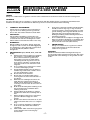
BELT AND
DISC SANDER
■ STOCK No.50021
■ PART No.BDS368
• INSTRUCTIONS •
IMPORTANT: PLEASE READ THESE INSTRUCTIONS CAREFULLY TO ENSURE THE
SAFE AND EFFECTIVE USE OF THIS TOOL.
02/2001
GENERAL INFORMATION
This manual has been compiled by Draper Tools and is an integrated part of the power tool equipment, which
should be kept with the machine.
This manual describes the purpose for which this tool has been designed and contains all the necessary
information to ensure its correct and safe use.We recommend that this manual is read before any operation of
the machine, before performing any kind of adjustment to the machine, and prior to any maintenance tasks. By
following all the general safety instructions contained in this manual, it will ensure both machine and operator
safety, together with longer life of the tool itself.
All photographs and drawings in this manual are supplied by Draper Tools to help illustrate the operation of the
machine.
Whilst every effort has been made to ensure accuracy of information contained in this manual, the Draper Tool
policy of continuous improvement determines the right to make modifications without prior warning.
BELT AND DISC SANDER
■ STOCK No.50021
CONTENTS:
■ PART No.BDS368
Page No.
Contents/Declaration ..................................................................................... 1
Specification/Guarantee ................................................................................. 2
Power Supply .................................................................................................. 3
Safety Warning/General Safety Instructions ................................................... 4
Safety Instructions for Belt & Disc Sanders ..................................................... 5
Unpacking ...................................................................................................... 6
Know your Belt & Disc Sander ........................................................................ 7
Assembly ................................................................................................. 8 - 10
Operation .............................................................................................. 10 - 13
Maintenance/Troubleshooting ...................................................................... 14
Optional Accessories .................................................................................... 15
DECLARATION OF CONFORMITY
We
Draper Tools Ltd. Hursley Road, Chandler’s Ford, Eastleigh, Hampshire.
SO53 1YF. England.
Declare under our sole responsibility that the product:
Stock Nos:- 50021.
Part Nos:- BDS368.
Description:- Belt & Disc Sander.
To which this declaration relates is in conformity with the following directive(s)
73/23/EEC & 89/336/EEC.
With reference to: BS3456: Part 201:1990.
JOHN DRAPER
Managing Director
25/07/96
-1-
SPECIFICATION
The Draper Tools policy of continuous improvement determines the right to change specification
without notice.
Part No. ................................................................................................................ BDS368
Stock No. ................................................................................................................ 50021
Belt size ...................................................................................................... 915 x 100mm
Belt table size ............................................................................................ 100 x 152mm
Belt table tilt .......................................................................................................... 0 - 45º
Belt speed ...................................................................................................... 290M/min.
Disc size .......................................................................................................... 200mm ø
Disc table size ............................................................................................158 x 266mm
Disc table tilt ........................................................................................................ 0 - 45º
Disc speed ........................................................................................................ 2850RPM
Motor .......................................................................................................... 350W (230V)
Dimensions ............................................................ (L)500mm x (W)233mm x (H)265mm
Weight .................................................................................................................... 20kg
Sound pressure level .......................................................................................... 70dB(A)
THIS BELT AND DISC SANDER IS DESIGNED SOLELY FOR WOOD, PLASTIC AND NONFERROUS
METALS ONLY. ANY OTHER MATERIALS WILL CAUSE DAMAGE TO THE PRODUCT.
WEAR EAR AND FACE PROTECTION.
GUARANTEE
Draper tools have been carefully tested and inspected before shipment and are guaranteed to be
free from defective materials and workmanship for a period of 12 months from the date of purchase
except where tools are hired out when the guarantee period is ninety days from the date of
purchase.
Should the machine develop any fault, pease return the complete tool to your nearest authorised
warranty repair agent or contact Draper Tools Limited, Hursley Road, Chandler’s Ford, Eastleigh,
Hampshire. SO53 1YF. England. Telephone: (023) 8026 6355.
If upon inspection it is found that the fault occurring is due to defective materials or workmanship,
repairs will be carried out free of charge. This guarantee does not apply to normal wear and tear,
nor does it cover any damage caused by misuse, careless or unsafe handling, alterations, accident,
or repairs attempted or made by any personnel other than the authorised Draper warranty repair
agent.
This guarantee applies in lieu of any other guarantee expressed or implied and variations of its
terms are not authorised.
Your Draper guarantee is not effective unless you can produce upon request a dated receipt or
invoice to verify your proof of purchase within the 12 month period.
Please note that this guarantee is an additional benefit and does not affect your statutory rights.
Draper Tools Limited.
-2-
POWER SUPPLY
CONNECTING YOUR MACHINE TO THE POWER SUPPLY: (230V ONLY)
To eliminate the possibility of an electric shock your machine has been fitted with a BS
approved, non rewireable moulded plug and cable which incorporates a fuse, the value
of which is indicated on the pin face of the plug. Should the fuse need to be replaced an
approved BS1362 fuse must be used of the same rating, marked thus
.
The fuse cover is detachable, never use the plug with the cover omitted. If a replacement
fuse cover is required, ensure it is of the same colour as that visible on the pin face of the
plug (i.e. red). Fuse covers are available from your Draper Tools stockist.
If the fitted plug is not suitable, it should be cut off and destroyed. *The end of the cable
should now be suitably prepared and the correct type of plug fitted. See below.
*WARNING:
A plug with bare flexible wires exposed is hazardous if engaged in a live power socket
outlet.
WARNING: THIS APPLIANCE MUST BE EARTHED.
Green and Yellow - Earth, Blue - Neutral, Brown - Live.
As these colours may not correspond with the coloured markings identifying the
terminals in your plug, proceed as follows:
The wire which is coloured green and yellow must be connected to the terminal the plug
which is marked with the letter ‘E’ or by the symbol
or coloured green or green and
yellow.
The wire which is coloured blue must be connected to the terminal which is marked with
the letter ‘N’ or coloured black or blue.
The wire which is coloured brown must be connected to the terminal which is marked
with the letter ‘L’ or coloured red or brown.
N.B. Three phase machines must be connected by a qualified electrician.
EXTENSION LEAD CHART:
Extension lead sizes shown assure a voltage drop of not more than 5% at rated load of tool.
Ampere rating
(on Name plate)
Extension cable length
7.5m
15m
22.5m
30m
45m
3
6
0.75
0.75
0.75
0.75
0.75
0.75
0.75
0.75
0.75
1.25
10
13
1.0
1.0
1.0
1.25
1.5
1.25
1.5
1.5
1.5
2.5
Wire Size mm2
-3-
GENERAL SAFETY INSTRUCTIONS
FOR POWER TOOLS
WARNING
Please read the following instructions carefully, failure to do so could lead to serious personal injury.
IMPORTANT
Draper Tools Limited recommends that this machine should not be modified or used for any application other
than that for which it was designed. If you are unsure of its relative applications do not hesitate to contact us in
writing and we will advise you.
1.
2.
3.
4.
5.
6.
7.
8.
9.
10.
11.
12.
13.
14.
KNOW YOUR POWER TOOL
Read and understand the owner's manual and labels
affixed to the tool. Learn its application and limitations as
well as the specific potential hazards peculiar to this tool.
KEEP WORK AREA CLEAN
Cluttered areas and benches invite accidents. Floors must
not be slippery due to oil or sawdust.
AVOID DANGEROUS ENVIRONMENTS
Do not use power tools in damp or wet locations, or
expose them to rain. Keep work area well lit. Provide
adequate space surrounding the work area. Do not use in
environments with a potentially explosive atmosphere.
KEEP CHILDREN AWAY
All visitors should be kept a safe distance from work area.
STORED TOOLS
When not being used, all tools should be stored in a dry,
locked cupboard or out of the reach of children.
WEAR PROPER CLOTHING
Do not wear loose clothing, neckties or jewellery (rings,
wristwatches) to catch in moving parts. NONSLIP footwear
is recommended.Wear protective hair covering to contain
long hair. Roll long sleeves above the elbow.
USE SAFETY GOGGLES (Head Protection)
Wear CE approved safety goggles at all times. Normal
spectacles only have impact resistant lenses, they are
NOT safety glasses. Also, use face or dust mask if
application is dusty and ear protectors (plugs or muffs)
during extended periods of operation.
NOISE LEVELS
Some types of machines may have high noise levels when
working. In such cases ear protection must be worn.
VIBRATION LEVELS
Hand held power tools produce different vibration levels.
You should always refer to the specifications and relevant
Health and Safety guide.
DUST EXTRACTION
If your tool is fitted with a dust extraction fitting, always
ensure that it is connected and being used with a dust
extractor.Vacuum cleaners can be used if suitable for the
material being extracted.
PROTECT YOURSELF FROM ELECTRIC SHOCK
When working with power tools, avoid contact with any
earthed items (e.g. pipes, radiators, hobs and
refrigerators, etc.). If you are using a power tool in
extreme conditions (e.g. high humidity or generating
metal dust), always use an RCD (residual current device)
at the power socket.
STAY ALERT
Always watch what you are doing and use common sense.
Do not operate a power tool when you are tired or under
the influence of alcohol or drugs.
WHEN WORKING OUT OF DOORS
Only use extension leads designed for that purpose.
ACCESS TO MAINS SOCKET
If a stationary machine is fitted with a moulded plug and
cable, the machine should not be positioned so that
access to the mains socket is restricted.
15.
16.
17.
18.
19.
20.
21.
22.
23.
24.
25.
26.
27.
28.
29.
30.
DISCONNECT POWER TO THE TOOL
When not in use, before servicing and when changing
accessories such as cutters, etc.
AVOID ACCIDENTAL STARTING
Make sure the switch is in the OFF position before
plugging the machine into the power supply.
NEVER LEAVE MACHINE RUNNING UNATTENDED
Turn power off. Do not leave machine until it comes to a
complete stop.
DO NOT ABUSE THE CORD
Never carry the tool by the power cable or pull it from
the socket. Keep the power cable away from heat, oil and
sharp edges.
NEVER STAND ON TOOL
Serious injury could occur if the tool is tipped or if the
cutting tool is accidentally contacted. Do not store
materials above or near the tool, so that it is necessary to
stand on the tool to reach them.
CHECK DAMAGED PARTS
Check for damage to parts, breakage of parts, mountings
and any other conditions that may affect its operation.
A guard or other part that is damaged should be properly
repaired or replaced.
KEEP GUARDS IN PLACE
And in working order.
MAINTAIN TOOLS WITH CARE
Keep tools sharp and clean for the best and safest
performance. Follow instructions for lubricating and
changing accessories. All extension cables must be
checked at regular intervals and replaced if damaged.
Always keep the hand grips on the tool clean, dry and
free of oil and grease.
USE RECOMMENDED ACCESSORIES
Consult the owners manual for recommended
accessories. Follow the instructions that accompany the
accessories. The use of improper accessories may cause
hazards.
REMOVE ADJUSTING KEYS AND WRENCHES
Form a habit of checking to see that keys and adjusting
wrenches are removed from the tool before turning it on.
SECURE WORK
Use clamps or a vice to hold work. This frees both hands
to operate the tool.
DO NOT OVERREACH
Keep proper footing and balance at all times.
USE RIGHT TOOL
Do not force the tool or attachment to do a job for which it
was not designed.
DO NOT FORCE TOOL
It will do the job better and safer at the rate for which it
was designed.
DIRECTION OF FEED
Feed work into a blade or cutter against the direction of
rotation of the blade or cutter only.
WHEN DRILLING OR SCREWING INTO WALLS
Always make sure there is no danger of hitting any hidden
power cables, water or gas pipes in the wall.
IMPORTANT NOTE
Residual Risk. Although the safety instructions and operating manuals for our tools contain extensive
instructions on safe working with power tools, every power tool involves a certain residual risk which can not be
completely excluded by safety mechanisms. Power tools must therefore always be operated with caution !
-4-
ADDITIONAL SAFETY RULES
FOR BELT & DISC SANDERS
SAFETY
Safety is a combination of operator common sense and alertness at all times when the sander is being used.
WARNING
For your own safety, do not attempt to operate the belt and disc sander until it is completely assembled and
installed according to the instructions and until you have read and understand the following.
1.
STABILITY OF MACHINE:
There may be a tendency for the machine to
tip over or move during certain operations,
due to this, the sander must be bolted down.
2.
LOCATION:
The machine should be positioned so the
operator or a casual observer are not forced
to stand in line with the sanding belt or disc.
This machine is intended for indoor use only.
3.
4.
5.
6.
KICKBACK:
When sanding on the disc, always apply the
workpiece left of centre of the disc. Applying
the workpiece to the right side could cause it
to fly up (kickback) which could be
dangerous.
7.
If any part of this belt and disc sander breaks,
bends, or fails in any way, or any electrical
component fails to perform properly, or if any
part is missing, turn off power switch, remove
plug from the power supply and replace
damaged, missing and/or failed parts before
resuming operation.
Do not sand with the workpiece unsupported.
Support it with the backstop or worktable. The
only exception is curved work performed on
the outer end of the belt (idler roller).
THINK SAFETY:
Safety is a combination of operator common
sense and alertness at all times when the
sander is in operation.
CAUTION:
This Belt and Disc Sander is designed solely for
wood, plastic and nonferrous metals only. Any other
materials will cause damage to the product or risk
of fire.
PROTECTION: eyes, hands, face, ears and
body:
(a) Always wear safety goggles (not glasses)
that comply to a recognised standard.
Wear a face mask if the operation is
dusty.Wear ear plugs or muffs during
extended periods of operation. Do not
wear gloves, jewellery or watches. Roll
long sleeves above the elbow. Tie back
long hair.
(b) Do not sand pieces of material too small
to hold comfortably by hand.
(c) Avoid awkward hand positions, where a
sudden slip could cause a hand to move
into the sanding disc or belt.
(d) Never stand on the machine.
(e) Never turn your sander “ON” before
clearing the belt table and worktable of
all objects.
(f)
Make sure the sanding belt runs in the
right direction (directional arrow on
inside of belt). Always have it adjusted
correctly so that the belt does not run off
the rollers.
(g) Hold the work firmly when sanding on the
belt and against the worktable when
sanding on the disc.
(h) Always adjust the worktable to within a
maximum of 2mm off the sanding disc or
belt.
(i)
When sanding a large piece of material,
provide additional support at table
height.
(j)
Never leave when the machine is on, wait
until the machine has come to a complete
stop.
(k) Do not perform assembly or adjustment
work on the table while the sander is
operating.
(l)
Turn sander “OFF” and remove plug from
power supply before removing any
accessories.
-5-
UNPACKING & CHECKING CONTENTS
Carefully unpack the sander and all the loose parts from the carton.
Fig.1 illustrates the sander and all the associated parts. Check that all of the parts are
present. If some parts are missing, contact the Draper Helpline on (023) 8049 4344.
Fig.1
-6-
KNOW YOUR BELT & DISC SANDER
✕✙✌
✕✗✌
✙✌
✕✕✌
✛✌
✚✌
✕✔✌
✕✘✌
✗✌
✕✖✌
✛✌
✢✌
✕✌
✜✌
✗✌
✕✖✌
✖✌
✕✙✌
✘✌
✜✌
Fig.2
1.
2.
3.
4.
5.
6.
7.
8.
Sanding disc
Work table
Mitre gauge
Disc guard
Table tilt locking bolt
Drive belt cover
Work support table
No-volt ON/OFF switch
9. Sanding belt
10. Backstop
11. Dust extraction outlet
12. Sanding plate
13. Belt tracking knob
14. Dust deflector
15. Sanding belt tensioning lever
16. BS moulded plug and cable
-7-
✕✚✌
ASSEMBLY
MOUNTING THE SANDER TO A
WORKBENCH (Fig.3):
The sander should be fastened securely
to a firm supporting surface such as a
workbench. If mounting to a workbench,
place the sander in a suitable position
and mark the surface through the holes
in the base ✪✌. Remove the sander and
drill the holes, align and insert the bolts
and nut securely (fixings not supplied).
INSTALLING THE SANDING DISC
TABLE (Figs.4 & 5):
Locate the table ✫✌, bracket ✬✌ and
securing handle ✭✌. Remove the bolts
from the underside of the table and fit
the bracket. Now offer up the assembly
to the sander. Insert the locating lug into
the hole in the housing and secure it in
place with the locking handle ✭✌.
Using an engineers square (for example
Draper Stock No.34065), adjust the table
so it is square with the sander and
running parallel across the disc face
(approx. 2mm gap), then tighten the
bolts holding the bracket to the table.
INSTALLING THE DUST DEFLECTOR
(Fig.6):
Locate the pegs on each side of the dust
deflector ✮✌ into the slots on the dust
collection cover ✯✌.
Fig.3
✪✌
Fig.4
✫✌
✬✌
✭✌
Fig.5
2mm
Fig.6
✯✌
-8-
✮✌
ASSEMBLY
INSTALLING THE BACK STOP (Fig.7):
Fix the back stop ✰✌ in place on the
back of the sanding belt assembly and
adjust it with 1.5mm gap to allow
sawdust to flow under.
INSTALLING THE WORK SUPPORT
TABLE (Figs.8 & 9):
Bolt the support bracket ✱✌ to the
sanding belt assembly. Assemble the
table to the locking bracket ✲✌.
Slide the assembled guide onto the
support bracket and lock into place with
the locking knob. Use the engineers
square to adjust the guide so it is square
with the sanding belt. When in place
lock off with the securing screw.
NOTE: The angle adjustment is only to
be used as a guide.
Fig.7
Fig.8
✰✌
✱✌
Fig.9
✲✌
VERTICAL SANDING (Fig.10):
For the sanding belt to be used in the
vertical position, the back stop, support
table and bracket must all be removed.
Loosen the locking bolt ✳✌ and put the
belt in the upright position and then
retighten the bolt. Next the sanding disc
table must be removed and fitted in the
same way, but using the fixture holes in
the side of the sanding belt assembly.
Fig.10
✳✌
-9-
ASSEMBLY
SAW DUST EXTRACTION (Fig.11):
It is recommended that the sander is
connected to a vacuum cleaner (for
example Draper Stock No.64674) during
operation, which will provide fast and
efficient removal of saw dust.
Fig.11
NOTE: Due to the large size outlet for
the dust extraction, Stock
No.29786 hose and 29791
adaptor are recommended.
OPERATION AND USE
NO-VOLT ON/OFF SWITCH (Fig.12):
Note: The BDS368 is fitted with a no-volt
on/off switch.
In the event of a power failure the machine
will have to be manually restarted.
To switch the machine on, push the
button marked ✲✌.
To switch the machine off, push the
button marked ✸✌.
To switch the machine off in an emergency
strike the ✸✌ button. Fig.12.
Fig.12
- 10 -
OPERATION AND USE
STRAIGHT SANDING (Fig.13):
Hold the work firmly with both hands,
keeping fingers away from the belt.
Straight pieces shorter than the belt table are
sanded by holding the workpiece lightly
against the belt. Move it back and forth
across the belt, keeping the end butted
against the stop fence. This fence prevents
the workpieces from slipping off the table.
USE EXTRA CAUTION WHEN SANDING THIN
PIECES. When finishing long pieces, remove
the stop fence. Start the work at one end and
gradually push it to the other end. Feed it
slowly across the width, at the same time,
apply only enough pressure to allow the belt
to remove material. If the belt stalls and belt
pulleys slip while applying moderate
pressure, the belt requires more tension.
END SANDING ON THE SANDING BELT
(Fig.14):
It is more convenient to sand the ends of long
workpieces with the sanding belt in a vertical
position. Move the work evenly across the
sanding belt.
Fig.13
Fig.14
- 11 -
CONTOUR SANDING (Fig.15):
Inside contours: Inside curves can be
sanded on the drums at either end of
the machine. Hold the work firmly, press
the contour lightly against the drum on
one side and move the work slowly
across the drum while moving up the
contour against the drum.
Outside contours: Outside curves can
be sanded on the belt table of the
unsupported side of the belt with the
table in the vertical position.
Hold the work firmly. Begin the curve
lightly against one side and feed it
across the belt towards the other side
while moving up the contour of the
workpiece.
Outside contours on the end of a
workpiece can be sanded with the
sanding disc. Feed the work lightly
against the disc and move it back and
forth from the centre of the disc to the
outside edge.
DISC SANDING (Fig.16):
Disc sanding should be done on the
outer edge of the disc which revolves
downward. Applying the workpiece to
the “UPSIDE” of the disc may cause it to
fly up, which could be dangerous to the
operator.
The mitre gauge ✳✌ is very useful as a
guide when chamfering and finishing
angle sanding.
- 12 -
OPERATION AND USE
REPLACING THE SANDING BELT AND
TRACKING (Fig.17):
WARNING - TO AVOID INJURY FROM
ACCIDENTAL STARTING, TURN THE
POWER SWITCH “OFF” AND REMOVE
THE PLUG FROM THE POWER SUPPLY
BEFORE REMOVING OR INSTALLING
SANDING BELTS.
On the inside of the sanding belt you will find
“direction arrows”. The sanding belt must run
in the direction of these arrows so that the
splice does not come apart.
1. Loosen the bed locking screw ✴✌ and lift
the bed to approx. 45º, Fig.17.
2. Slide the tension lever ✵✌ to the left to
release the belt tension.
3. Place the sanding belt over the pulleys
with the directional arrows pointing in an
anticlockwise direction when looking at
the sander from the disc side. Make sure
the belt is centred on both pulleys.
4. Tension the sanding belt by sliding the
tension lever back.
5. Re-connect to the power supply. Turn
switch “ON” and immediately “OFF”,
noting if the belt tends to slide off the
idler pulley or drive pulley. If the belt did
not try to slide off, it is tracking correctly.
6. If the belt moves towards the disc, turn the
tracking knob ✶✌ anticlockwise 1⁄4 of a
turn, Fig.18.
7. If the sanding belt moves away from the
disc, turn the tracking knob ✶✌ clockwise
1
⁄4 of a turn.
8. Turn the switch “ON” and immediately
“OFF” again, noting any belt movement.
Re-adjust the tracking knob if necessary.
REPLACING THE SANDING DISC (Fig.19):
With the table removed, dismantle the
sanding disc guard ✷✌ by removing the
screws. Pull off the used disc and stick the
new adhesive backed disc centrally on the
disc.
Fig.17
✴✌
✵✌
Fig.18
✶✌
✷✌
Fig.19
Fig.20
✹✌
CHANGING THE DRIVE BELT (Fig.20):
Remove the single screw and take off
covering plate ✸✌. Loosen the three bolts
✹✌ and push the housing so the drive belt
becomes slack. Remove and replace the belt,
re-tension the housing so the belt is
sufficiently tight and secure housing bolts.
Refit cover ✸✌.
✸✌
- 13 -
MAINTENANCE
WARNING: FOR YOUR OWN SAFETY, TURN
SWITCH “OFF” AND REMOVE THE PLUG
FROM THE POWER SUPPLY OUTLET BEFORE
ADJUSTING, MAINTAINING, OR LUBRICATING
YOUR BELT AND DISC SANDER.
Do not apply wax to the abrasive belt table
because the belt could pick up the wax and d
deposit it on the pulleys, causing the belt to
slip.
If power cable is worn, cut, or damaged in any
way, have it replaced immediately.
Keep machine clean and remove
accumulations of dust.
Frequently blow out or vacuum out any dust
that may accumulate inside the motor.
A coat of wax polish applied to the worktable
will make it easier to feed the work while
finishing.
LUBRICATION:
The BALL BEARINGS in this machine are
packed with grease at the factory. They require
no further lubrication.
TROUBLE SHOOTING
WARNING: FOR YOUR OWN SAFETY, TURN SWITCH “OFF” AND REMOVE PLUG FROM THE POWER
SUPPLY OUTLET BEFORE TROUBLE SHOOTING YOUR BELT AND DISC SANDER.
TROUBLE
PROBABLE CAUSE
REMEDY
Motor will not run.
1. Defective ON/OFF switch.
1. Replace defective parts
before using belt and
disc sander again.
2. Burned out motor.
Machine slows down
when sanding.
2. Any attempt to repair this
motor may create a
HAZARD unless repair
is done by a qualified
service technician.
1. Drive belt too tight.
1. Decrease belt tension.
2. Applying too much
pressure to workpiece.
2. Ease up on pressure
Sanding belt runs off pulleys.
1. Not tracking properly.
1. Adjust tracking, see
Operation & Use Section
“Replacing the Sanding
Belt - Tensioning and
Tracking” on page 13.
Wood burns while sanding.
1. Sanding disc or belt is.
glazed with sap.
1. Replace disc or belt.
IMPORTANT:
PLEASE NOTE ALL REPAIRS/ADJUSTMENTS SHOULD BE CARRIED OUT BY A QUALIFIED PERSON.
SHOULD THE SANDER REQUIRE SENDING TO A SERVICE/REPAIR AGENT, FOR A HEALTH AND
SAFETY POINT, ENSURE IT IS CLEAN OF DUST AND DEBRIS.
DRAPER HELPLINE: (023) 8049 4344
- 14 -
OPTIONAL ACCESSORIES
The following accessories are available from your local Draper stockist:
SANDING DISCS:
PART No.
STOCK No.
GRIT GRADE
PACK QUANTITY
SD8
51005
60
5 discs
SD8
51006
80
5 discs
SD8
51007
100
5 discs
SD8
51008
120
5 discs
SD8
51009
Assorted
5 discs
PART No.
STOCK No.
GRIT GRADE
PACK QUANTITY
SD8V
52607
60
5 discs
SD8V
52608
80
5 discs
SD8V
52609
100
5 discs
SD8V
52610
120
5 discs
SD8V
52611
Assorted
5 discs
HOOK & LOOP SANDING DISCS:
SELF ADHESIVE/HOOK & LOOP PAD 8”:
PART No.
STOCK No.
GRIT GRADE
PACK QUANTITY
SD8VP
52612
-
1
PART No.
STOCK No.
GRIT GRADE
PACK QUANTITY
SB436
25958
60
3
SB436
25959
80
3
SB436
25960
100
3
SB436
25962
120
3
SB436
25963
Assorted
3
SANDING BELTS:
- 15 -
NOTES
- 16 -
NOTES
- 17 -
NOTES
- 18 -
DRAPER TOOLS LIMITED,
Hursley Road, Chandler's Ford, Eastleigh, Hants. SO53 1YF. U.K.
Helpline: (023) 8049 4344.
Sales Desk: (023) 8049 4333.
General Enquiries: (023) 8026 6355.
Fax: (023) 8026 0784.
www.draper.co.uk
e-mail: [email protected]
YOUR DRAPER STOCKIST
©Published by Draper Tools Ltd.
No part of this publication may be reproduced,
stored in a retrieval system or transmitted in
any form or by any means, electronic, mechanical
photocopying, recording or otherwise without prior
permission in writing from Draper Tools Ltd.