1
Operator's Manual
Model SM4020 20 Channels Relay Multiplexer
Model SM4022 20 Channels Instrumentation Relay
Multiplexer
Model SM4040 40 Channels Relay Multiplexer
Model SM4042 40 Channels Instrumentation Relay
Multiplexer
Signametrics Corporation
March, 2006
CAUTION
In no event shall Signametrics or its Representatives be liable for any consequential damages whatsoever (including,
without limitation, damages for loss of business profits, business interruption, loss of business information, or other
loss) arising out of the use of or inability to use Signametrics’ products, even if Signametrics has been advised of
the possibility of such damages. Because some states do not allow the exclusion or limitation of liability for
consequential damages, the above limitations may not apply to you.
© 2000 Signametrics Corp. Printed in the USA. All rights reserved. Contents of this publication must not be
reproduced in any form without the permission of Signametrics Corporation.
Signametrics
2
TABLE OF CONTENTS
1.0 INTRODUCTION .................................................................................................................................................5
1.1 SAFETY CONSIDERATIONS ..........................................................................................................................5
1.2 MINIMUM REQUIREMENTS .........................................................................................................................5
1.3 DESCRIPTION ..............................................................................................................................................6
1.4 CONFIGURATIONS.......................................................................................................................................7
1.5 SELF TEST AND CONTACT CLEANING .........................................................................................................7
2.0 SPECIFICATIONS AND FEATURE TABLE ...................................................................................................8
2.1 TRIGGER INPUT ..........................................................................................................................................8
2.2 TRIGGER OUTPUT .......................................................................................................................................9
2.3 OTHER SPECIFICATIONS .............................................................................................................................9
3.0 GETTING STARTED...........................................................................................................................................9
3.1 SETTING THE SCANNER ..............................................................................................................................9
3.2 INSTALLING THE SOFTWARE.....................................................................................................................10
3.3 INSTALLING THE SCANNER MODULE ........................................................................................................10
3.4 SCANNER CONNECTOR PIN-OUT ...............................................................................................................10
3.5 STARTING THE CONTROL PANEL ..............................................................................................................13
3.6 USING THE CONTROL PANEL ....................................................................................................................14
4.0 SCANNER TUTORIAL .....................................................................................................................................15
4.1 SCANNER CONFIGURATIONS.....................................................................................................................15
4.1.1 Two Wire Multiplexing ..........................................................................................................16
4.1.2 Four Wire Multiplexing .........................................................................................................16
4.1.3 Six Wire Multiplexing ............................................................................................................17
4.1.4 Two Groups Configuration ....................................................................................................17
4.1.5 Four Groups Configuration...................................................................................................18
4.1.6 Disabled .................................................................................................................................18
4.2 SCANNER OPERATIONS.............................................................................................................................18
4.2.1 Trigger Output .......................................................................................................................18
4.2.2 Trigger Input..........................................................................................................................19
4.2.3 Auto Scan Operation..............................................................................................................19
4.2.4 Triggered Auto Scan Operation.............................................................................................19
4.2.5 Triggered Scan Operation .....................................................................................................20
4.2.6 Single Step Scan Operation ...................................................................................................20
4.2.7 Scan List Operations..............................................................................................................21
4.2.8 Locating Shorted Channel .....................................................................................................21
4.2.9 Cleaning Relays Contacts ......................................................................................................22
4.2.10 Integrity Test ........................................................................................................................22
4.2.11 Self Tests ..............................................................................................................................22
4.2.12 Setting Actuation Time Parameter.......................................................................................22
4.2.13 Setting Step Time Parameter ...............................................................................................23
4.2.14 Thermocouple Temperature Measurements.........................................................................23
4.3 POLLED TYPE OPERATIONS ......................................................................................................................23
4.4 INTERFACING TO THE SM2040 SERIES 6-1/2 DIGIT DMM........................................................................24
4.4.1 Triggering the SM2040 DMMs..............................................................................................24
4.4.2 Multiplexing with the SM2040 DMMs ...................................................................................24
4.4.3 Interface Commands and Timing...........................................................................................24
4.5 SINGLE ENDED APPLICATION EXAMPLE ...................................................................................................25
4.5.1 Point to Point Configuration .................................................................................................25
4.5.2 An 84 Point, Single End Configuration .................................................................................26
5.0 SM4040 SCANNER FAMILY WINDOWS INTERFACE..............................................................................26
5.1 DISTRIBUTION FILES ................................................................................................................................26
3
Signametrics
5.2 USING THE SM4040 DRIVER WITH C++ OR SIMILAR SOFTWARE .............................................................27
5.2.1 Multiple Card Operations under Windows............................................................................28
5.3 VISUAL BASIC FRONT PANEL APPLICATION .............................................................................................29
5.3.1 Visual Basic Simple Application ............................................................................................29
5.4 WINDOWS DLL DEFAULT MODES AND PARAMETERS ..............................................................................30
5.5 USING THE SM4040 DLL WITH LABWINDOWS/CVI® ............................................................................31
5.6 WINDOWS COMMAND LANGUAGE ...........................................................................................................31
SCANAbort......................................................................................................................................31
SCANAutoScan ...............................................................................................................................32
SCANCleanRelays...........................................................................................................................33
SCANClosePCI ...............................................................................................................................34
SCANDelay .....................................................................................................................................34
SCANErrString ...............................................................................................................................35
SCANGetActuationTime .................................................................................................................36
SCANGetBusInfo.............................................................................................................................36
SCANGetConfig ..............................................................................................................................37
SCANGetGrdVer.............................................................................................................................37
SCANGetHwVer..............................................................................................................................38
SCANGetID.....................................................................................................................................38
SCANGetManDate..........................................................................................................................39
SCANGetScanList ...........................................................................................................................39
SCANGetShortedChannel ...............................................................................................................40
SCANGetStepTime ..........................................................................................................................40
SCANGetTriggerIn .........................................................................................................................41
SCANGetType .................................................................................................................................41
SCANGetVer ...................................................................................................................................42
SCANInit .........................................................................................................................................42
SCANIsInitialized............................................................................................................................43
SCANOpenAllChannels ..................................................................................................................43
SCANOpenPCI................................................................................................................................44
SCANReady.....................................................................................................................................44
SCANSelectChannel........................................................................................................................45
SCANSelectChannelCmd ................................................................................................................46
SCANSetActuationTime ..................................................................................................................46
SCANSetChannelRelay ...................................................................................................................47
SCANSetConfig ...............................................................................................................................48
SCANSetConfigRelay ......................................................................................................................48
SCANSetScanList ............................................................................................................................49
SCANSetStepTime ...........................................................................................................................50
SCANSetTriggerOut........................................................................................................................50
SCANSetupStep ...............................................................................................................................51
SCANStep........................................................................................................................................51
SCANStepCmd ................................................................................................................................52
SCANTerminate ..............................................................................................................................53
SCANTestChanIntegrity..................................................................................................................53
SCANTestChannelRelay .................................................................................................................54
SCANTestConfigRelay ....................................................................................................................54
SCANTrigAutoScan.........................................................................................................................55
SCANTriggerInState .......................................................................................................................56
SCANTriggerOutState.....................................................................................................................56
SCANTrigScan ................................................................................................................................57
6.0 ACCESSORIES...................................................................................................................................................59
7.0 WARRANTY AND SERVICE...........................................................................................................................59
Signametrics
4
1.0 Introduction
Congratulations! You have purchased a Personal Computer (PC) Plug-in instrument with analog and systems
performance that rivals the best, all-in-one box, instruments. The SM4040 series relay scanner/multiplexer are easy
to setup and use, have sophisticated analog and digital circuitry to provide very repeatable switching. Please take a
few moments and review this manual before installing and using this instrument.
This manual describes the SM4020, SM4022, SM4040, and SM4042 Scanners. Each delivers unmatched switching
performance in a PCI plug-in instrument. With a rich repertoire of functions, the SM4040 series out performs all
other plug-in Scanners, including most brand-name bench top units.
Note: In this manual, all references to the "SM4000" and “Scanner” applies to the SM4020, SM4022, SM4040, and
SM4042. Features unique to each product will be identified as such.
1.1 Safety Considerations
Safety Considerations
The SM4000 series of Scanners are capable of switching 110 VDC or 220, depending on model number,
across the High and Low terminals. They can also handle common mode signals that "float" the Scanner
above EARTH ground by up to 110 VDC or 220 VAC, depending on the model. When making common
mode switching, the majority of the circuits inside the Scanner are at the common mode voltage. These
voltages can be lethal and may KILL! During and after installing your Scanner, check to see that
there are no wires or ribbon cables from your PC trapped inside the Scanner.
The Scanner comes installed with four shields (bottom, top, and two edge strips) that must not be
removed for performance as well as safety reasons. Removal of these shields and/or improper
assembly of the shields can result in lethal voltages occurring within your PC. Be sure to check your
installation before closing the cover on your personal computer.
Warning
Check to see that no loose wires or ribbon cables infringe upon any of the internal circuits of the
Scanner, as this may apply lethal voltages to your computer, causing electrocution and/or damage to
your computer!
To avoid shock hazard, install the Scanner only into a computer that has its power connector
connected to a power receptacle with an earth safety ground.
When connecting to signals above 50 VDC or 40 VAC, only use Safety Test Leads and harnesses.
1.2 Minimum Requirements
The SM4040 series of system relays Scanners are plug-in modules that are compatible with IBM type personal
computers (PCs), from the 486 class to the Pentiums. They require a half-length expansion slot on the PCI bus. A
mouse must be installed when controlling the Scanner from the Windows Control Panel. The SM4040 comes with a
Windows' DLL, for operation with Windows' Version 95/98 and NT4.0, Windows 2000 or greater.
5
Signametrics
1.3 Description
The SM4020 and SM4022 are 20 channel models arranged in two groups of 10:1 differential channels. The
SM4040 and SM4042 are 40 channel models arranged in four groups of 10:1 differential channels. The “2” suffix
indicates an instrumentation quality scanning structure, while the “0” indicates standard general purpose scanning
structure. The Instrumentation models are necessary in applications requiring precision and low leakage. The most
outstanding feature of the Instrumentation models is a very low Thermal EMF, resulting is highly accurate Ohms,
low Voltage, temperature and other sensitive stimulus and measurements. The standard scanners in this family, the
SM4020 and SM4040, exhibit much lower Thermal EMF than most other plug-in relay scanners.
When using an SM2020 or an SM2040 series 5-1/2 and 6-1/2 DMMs, or similar DMM, it is necessary to use the
Instrumentation quality scanners in order to maintain full measurement accuracy.
These scanners are software configurable on the fly, and can handle several pre-defined switching configurations,
such as TwoWire, FourWire, SixWire, Universal, TwoGroups, FourGroups, and Disabled. In the TwoWire
configuration, the scanner acts like a 20 or 40 channel multiplexer. In the FourWire configuration, it automatically
selects two simultaneous channels, allowing a DMM or other device to connect to four individual lines. In the
SixWire configuration six wires, or three differential channels are selected automatically, providing such
applications as six wire guarded in circuit measurements. The Universal configuration turns the scanner into a
pseudo matrix structure, allowing any relay, including channel relays, tree relays and configuration relays, to be
closed or open, including multiple relays. The TwoGroups and FourGroups configurations split the Scanner into
several independent Two-Wire multiplexers.
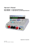
Figure 1-1. Simplified diagram of the SM4000 relay scanner.
In the TwoWire, FourWire, SixWire, TwoGroups, and FourGroups configuration, the switching sequence includes
the opening of the previously closed channels and then closing of the selected channels. In the case where multiple
channels are supposed to be closed, such as in FourWire configuration, these channels are closed simultaneously so
that no additional time beyond the actuation time is consumed. Break-before-make operation is maintained due to a
high speed turns off circuit, which shuts off the active coil current very quickly as compared to the turn on time.
Signametrics
6
1.4 Configurations
In addition to the channel switching relays, the SM4000 series includes two sets of relays used for configuring of
the scanner. The configuration switches facilitate inter-group connections and the Tree relays provide isolation of
each of the group’s buses from their respective channel relays. These relays are automatically switched on the fly
when the scanner receives configuration commands or changes are required while selecting channels from various
groups. In cases where the pre-defined configurations (TwoWire, FourWire, SixWire, TwoGroups, and FourGroups)
do not meet the test needs, select the Universal configuration. It allows an unlimited control any of the configuration
and tree relays independently. Care must be taken however, since it does not offer the protection of the predefined
configurations. This could result in shorting some “hot” lines, constituting in potential hazard to the user from any
thing that is connected to the scanner and from the scanner itself. This could also lead to damaging the scanner or
anything connected to it.
1.5 Self Test and Contact Cleaning
In addition to the channel relays, Tree relays and Configuration relays, there are additional relays and circuit
components that handle the various tests built into the Scanners. The user does not have direct control of these
components.
The test connector is used in various self tests and cleaning operations of the Scanner. It is a Female DIN 96
position connector which has 40 shorts across all Channels (Ch1Hi shorted to Ch1Lo etc.), and three shorts across
the B-Bus, C-Bus and D-Bus. All other terminals, including the A-Bus must be left open. This Test Connector is
optionally available from Signametrics.
7
Signametrics
2.0 Specifications and Feature Table
Function
SM4020
SM4022
SM4040
SM4042
Standard
Instrumentation
Standard
Instrumentation
Scanner
Scanner
Scanner
Scanner
Number of differential channels
20
40
20
40
Number of 10:1 groups
two
four
two
four
Scanning Arrangement
Two groups of 10:1 differential
Four groups of 10:1 differential
Thermal EMF offset (µV)
25
1.5
25
1.5
Maximum Switching DC Voltage (V)
110
220
110
220
Maximum Switching AC Voltage (V)
110
250
110
250
Maximum Switching Current (A)
1
1
1
1
Maximum Switching Current (A)
1
1
1
1
Typical inter-channel Capacitance
15pf
15pf
15pf
15pf
>100
>1,000
>100
>1,000
Insulation between open contacts (MΩ,)
>100
>1,000
>100
>1,000
Insulation; contacts to coils (MΩ)
>100
>1,000
>100
>1,000
Insulation; adjacent channels (MΩ)
No Load Life
2X10⁷
108
2X10⁷
108
5
6
5
Loaded Life @ 50Vdc, 0.1A
3X10
10
3X10
106
Trigger input
√
√
√
√
Trigger output
√
√
√
√
Thermocouple Cold Junction Capable
√
√
Typical Closure Time (ms)
12
4
12
4
Typical Release Time (ms)
5
2
5
2
Actuation Time (ms) [1]
15
5
15
5
Actuation Time Settable Range (ms)
1 to 850 in 0.25 steps
AutoScan Period Range (ms)
1 to 850 in 0.25 steps
Available Configurations
2-wire, 4-wire,
2-wire, 4-wire, 62-wire, 4-wire,
2-wire, 4-wire, 6universal, twowire, universal,
universal, twowire, universal,
groups
two-groups, fourgroups
two-groups, fourgroups
groups
Available Scan Groups
A and B
A, B, C and D
A and B
A, B, C and D
Isolated Relay Coil Drive
√
√
Maximum number of relays closed
All
All
All
40
High Ohms range 1,000 Meg
√
[1] Actuation time is the time it takes to open any closed relays, and close the selected relay.
Table 2-1. Specifications and Feature table.
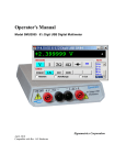
2.1 Trigger Input
Input Characteristics
• Input LED (nominal 1.7V drop at 1mA) with a series 1kΩ resistor.
• Input Signal requirements >2.5 V, < 10 V to activate. < 1V to deactivate.
• Isolation Optically Isolated from all other circuitry. Common line with Trigger Output.
Signametrics
8
Figure 2-1. Trigger input equivalent circuit.
2.2 Trigger Output
Output Characteristics
• Output Circuit Open collector of a NPN transistor (nominal 0.4V saturation voltage) in series with 1kΩ
resistor.
• Collector Emiter Voltage < 30 V
• Output Current < 4 mA
• Reverse Voltage < 7V
• Isolation Optically Isolated from all other circuitry. Common line with Trigger Input.
Figure 2-2. Trigger Output Optical Isolator NPN circuit.
2.3 Other Specifications
Hardware Interface
PCI Bus
Safety
Designed to IEC 1010-1, Installation Category I.
Temperature Range
0°C to 50°C, operating
Size
9.2” X 4.4”
Power
+5 volts, 550 mA maximum
Note: Signametrics reserves the right to make changes in materials, specifications, product functionality, or
accessories without notice.
3.0 Getting Started
After unpacking the Scanner, please inspect for any shipping damage that may have occurred, and report any claims
to your transportation carrier.
The Scanner package is shipped with the Scanner module, four floppy disks containing software drivers, user
interface panel, and this Operator's manual.
3.1 Setting the Scanner
The SM4040 series Relay Scanners are PCI plug-and-play devices and do not require any switch settings, or any
other adjustments to the hardware prior to installation.
9
Signametrics
3.2 Installing the Software
It is best to first plug the Relay Scanner into the PC chassis, and follow the instructions on the screen for ‘New
Hardware Found’. . The first time you power up your computer with the Scanner installed, your computer will
detect the new Scanner and prompt you for a driver. The driver your computer requires is on Disk 1 (SM4040.inf).
Guide the computer to search for device driver on Disk1. Next run ‘setup’ provided in Disk1.
After the computer completes its boot process run the ‘SETUP’ program provided on Disk 1, to install the software.
This takes care of all installation and registration requirements of the software.
3.3 Installing the Scanner Module
Warning
To avoid shock hazard, install the Scanner only into a personal computer that has its power line connector
connected to an AC receptacle with an Earth Safety ground.
After installation, check to see that no loose wires or ribbon cables infringe upon any of the internal circuits
of the Scanner, as this may apply measurement voltages to your computer, causing personal injury and/or
damage to your computer!
Caution: Only install the Scanner module with the power turned OFF to the PC!
Use extreme care when plugging the Scanner module(s) into a PCI bus slot. The Scanner comes a DIN 96 pin
connector. Because of its necessary size, it is a tight fit in many PC chassis. Insert the bracket end of the Scanner
into your PC first, watching for any interference between the DIN 96 connector and your PC chassis. “Sliding” the
bracket end of the Scanner into the chassis may be helpful. Be patient! You should only have to install it once!
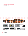
3.4 Scanner Connector Pin-out
Before using the Scanner, please take a few moments and review this section to understand where the multiplexed
and common signals are located in the DIN 96 position male connector are located. Under no circumstances
should voltage and current limits exceed the specified values, as personal injury or damage to the instrument,
your computer or application may result.
Figure 3-1. The Scanner’s DIN 96 connector, facing the bracket.
Pin #
1C
Label
Ch11Hi
Signametrics
Description
Channel 11 High
Pin #
17C
10
Label
Ch31Hi
Description
Channel 31 High
1B
1A
2C
2B
2A
3C
3B
3A
4C
4B
4A
5C
5B
5A
6C
6B
6A
7C
7B
7A
8C
8B
8A
9C
9B
9A
10C
10B
10A
11C
11B
11A
12C
12B
12A
13C
13B
13A
14C
14B
14A
15C
15B
15A
16C
16B
16A
Ch10Hi
Ch17Lo
Ch18Lo
Ch1Hi
Ch2Hi
Ch18Hi
Ch4Lo
Ch2Lo
Ch19Hi
Ch1Lo
Ch6Lo
Ch19Lo
Ch4Hi
Ch11Lo
Ch5Hi
Ch8Hi
Ch7Lo
Ch16Lo
Ch12Hi
Ch7Hi
Ch12Lo
Ch9Lo
Ch13Hi
Ch5Lo
Ch13Lo
Ch14Hi
Ch3Hi
Ch8Lo
Ch9Hi
Ch6Hi
Ch10Lo
Ch15Hi
Ch20Hi
Ch16Hi
Ch14Lo
Ch21Lo
Ch22Hi
Ch21Hi
Ch20Lo
Ch23Hi
Ch23Lo
Ch24Hi
Ch22Lo
Ch24Lo
Ch26Hi
Ch3Lo
Ch25Hi
Channel 10 High
Channel 17 Low
Channel 18 High
Channel 1 High
Channel 2 High
Channel 18 High
Channel 4 Low
Channel 2 Low
Channel 19 High
Channel 1 Low
Channel 6 Low
Channel 19 Low
Channel 4 High
Channel 11 Low
Channel 5 High
Channel 8 High
Channel 7 Low
Channel 16 Low
Channel 12 High
Channel 7 High
Channel 12 Low
Channel 9 Low
Channel 13 High
Channel 5 Low
Channel 13 Low
Channel 14 High
Channel 3 High
Channel 8 Low
Channel 9 High
Channel 6 High
Channel 10 Low
Channel 15 High
Channel 20 High
Channel 16 High
Channel 14 Low
Channel 21 Low
Channel 22 High
Channel 21 High
Channel 20 Low
Channel 23 High
Channel 23 Low
Channel 24 High
Channel 22 Low
Channel 24 Low
Channel 26 High
Channel 3 Low
Channel 25 High
17B
17A
18C
18B
18A
19C
19B
19A
20C
20B
20A
21C
21B
21A
22C
22B
22A
23C
23B
23A
24C
24B
24A
25C
25B
25A
26C
26B
26A
27C
27B
27A
28C
28B
28A
29C
29B
29A
30C
30B
30A
31C
31B
31A
32C
32B
32A
Ch25Lo
Ch26Lo
Ch31Lo
Ch27Hi
Ch27Lo
Ch33Hi
Ch28Hi
Ch15Lo
Ch33Lo
Ch17Hi
Ch29Hi
Ch36Lo
Ch28Lo
Ch29Lo
Ch39Lo
Ch30Hi
Ch30Lo
Ch37Hi
Ch32Hi
Ch35Hi
Ch38Hi
Ch32Lo
Ch34Lo
Ch40Hi
Ch37Lo
Ch34Hi
Ch38Lo
Ch35Lo
Ch36Hi
Ch39Hi
Ch40Lo
Channel 25 Low
Channel 26 Low
Channel 31 Low
Channel 27 High
Channel 27 Low
Channel 33 High
Channel 28 High
Channel 15 Low
Channel 33 Low
Channel 17 High
Channel 29 High
Channel 36 Low
Channel 28 Low
Channel 29 Low
Channel 39 Low
Channel 30 High
Channel 30 Low
Channel 37 High
Channel 32 High
Channel 35 High
Channel 38 High
Channel 32 Low
Channel 34 Low
Channel 40 High
Channel 37 Low
Channel 34 High
Channel 38 Low
Channel 35 Low
Channel 36 High
Channel 39 High
Channel 40 Low [1]
BHi
BLo
CHi
DHi
CLo
AHi
ALo
DLo
TRIG_out
TRIG_in
+5V
Common
TRIG_com
B-Bus High
B-Bus Low
C-Bus High
D-Bus High [1]
C-Bus Low
A-Bus High
A-Bus Low
D-Bus Low [1]
Trigger open collector out.
Trigger TTL input
+5V special supply
Return for +5V supply
Trig. input and output comn
[1] D-Bus is not available when using an Isothermal Terminal Block.
Table 3-1. The Scanner’s DIN 96 connector pin assignments.
11
Signametrics
ChxHi, ChxLo - These are the channel positive and negative terminals for all group channels, respectively. It starts
with Ch1Hi/Lo and ends with Ch20Hi/Lo with the 20 Channel scanners and Ch40Hi/Lo for the 40 Channel models.
Depending on the Scanner configuration, these lines are routed to the bus terminals AHi/Lo, BHi/Lo, CHi/Lo, or
DHi/Lo.
AHi, ALo - These are the A-bus positive and negative terminals respectively. The channels positive and negative
lines may be routed to these lines depending on Scanner configuration. In the Universal mode, it is also possible to
route bus pairs to other bus pairs.
BHi, BLo - These are the B-bus positive and negative terminals respectively. The channels positive and negative
lines may be routed to these lines depending on Scanner configuration. In the Universal mode, it is also possible to
route bus pairs to other bus pairs.
CHi, CLo - These are the C-bus positive and negative terminals respectively. The channels positive and negative
lines may be routed to these lines depending on Scanner configuration. In the Universal mode, it is also possible to
route bus pairs to other bus pairs.
DHi, DLo - These are the D-bus positive and negative terminals respectively. The channel positive and negative
lines may be routed to these lines depending on Scanner configuration. In the Universal mode, it is also possible to
route bus pairs to other bus pairs. It is important to note that when using the Isothermal Block the DHi and DLo
terminals should not be used, and a configuration involving them should not be selected. Therefore configurations
such as FourGroups or SixWire should not be selected, and when selecting Universal configuration, care must be
taken not to include these terminals.
TRIG_com - This is the TRIG_in and TRIG_out return terminal. Both of these signals are referenced to it. All
three signals associated with the trigger circuitry, TRIG_com, TRIG_in, and TRIG_out are optically isolated from
the rest of the terminals in the DIN 96 connector.
Figure 3-2. The trigger input and output lines are isolated by an optical isolators.
TRIG_in - This is the trigger input signal. It requires TTL or CMOS level (at least 2.5V) to activate the trigger
input. A series 1k removes the need to add external resistor and allows direct connection to a TTL or CMOS logic
source. It is referenced to the TRIG_com line.
TRIG_out - This is the trigger output signal. It is an open collector signal with 1k resistor in series. It will drive a
CMOS or TTL line provided it is connected to an appropriate positive supply (from 3V to 10V). It is referenced to
the TRIG_ com line.
+5V - This is a 5V supply line. It is designed to support the optional active Isothermal Block. It may also be used to
power the TRIG_out signal. When using it to power TRIG_out, it is recommended that a 10k be connected from
TRIG_out to it as in Figure 3-3. This supply may vary between 4.7V to 5.7V, and its usage should be limited to no
more than 10mA. This supply is isolated from the rest of the signals in the DIN 96 connector. This signal is
referenced to the Common line.
Signametrics
12
Common - This is the return line for the +5V supply. Since TRIG_com and Common are isolated from each other,
they must be connected as in Figure 3-3 if the +5V is used to power TRIG_com. This supply return is isolated from
the rest of the signals in the DIN 96 connector.
Figure 3-3. Trigger out may use the +5V supply provided for generating CMOS logic output.
3.5 Starting the Control Panel
After installing the software, you can verify the installation and gain familiarity with the Scanner by exercising its
measurement functions using the Windows based Control Panel. To run the control panel, double click the
‘SM4040.EXE’ icon. If you do not hear the relays click, you may have an installation error.
The Control Panel is operated with a mouse. All functions are accessed using the left mouse button.
Note: The SM4000 front panel powers up in Disabled mode, with all relays open.
13
Signametrics
3.6 Using the Control Panel
Figure 3-2. The Control Panel for the SM4040. The three main groups include the relays buttons, the configuration
selection options, and the main menu.
Note: All of the controls described below correspond to their respective software function, which can be invoked
within your control software or as objects in a visual programming environment. Using the software command
language of the SM4000 allows additional capabilities and functions that are not included in the control panel
above.
Relay Buttons - These buttons are context sensitive. Depending on the selected Configuration, these buttons allow
the closing and opening of the various channel relays. In the Universal configuration, the user has control over all
relays. In the FourWire and SixWire configurations, two and three relays are activated simultaneously. In the
TwoWire, FourWire, SixWire, TwoGroups and FourGroups function switches between DC and AC.
Edit Scanner Parameters - This panel provides means to enter the Relay Actuation time and the Step Times, as
well as the total number of steps in an AutoScan.
ScanList Editor - This panel provides means to edit the contents of the ScanList.
Signametrics
14
Configuration Option Checks - This section of the main panel allows the selection of one out of all of the possible
pre defined configurations. On power up, the configuration is set to Disabled. Possible selections include Disabled,
TwoWire, FourWire, SixWire, Universal, TwoGroups, and FourGroups.
Edit Menu - This menu item has three selections, setting all parameters to their default value, opening the Edit
Scanner Parameter sub-panel, and opening the Scan List Editor sub-panels.
Trigger Menu - This menu item controls the functionality of the scanner’s trigger input and output signals. It
enables or disabled the Trigger output, and sets the polarity of both Trigger input and output.
Tools Menu - This menu item provides access to some of the special test and cleaning tools. It includes the SelfCleaning function, the various self-tests, and the shorted input detector.
Operations Menu - This menu item allows running some of the special scanner’s operations such as AutoScan,
Triggered Scan, Triggered Auto Scan, and the setting and monitoring of the Trigger output and trigger input
respectively.
4.0 Scanner Tutorial
Most of the SM4000 functions are accessible from the control panel described in the previous section. This section
describes in detail the Scanner’s operations and practices. To gain familiarity with the SM4000 series Scanners, run
the Windows ‘SETUP.EXE’ to install the software, then run the Scanner control panel to demonstrate its operations.
4.1 Scanner Configurations
The various configurations maybe experimented with using the control panel. Connect to the Scanner’s terminals to
the appropriate channels and bus lines, making sure not to exceed any of the specifications and limits. Use the
control panel’s option checks to select the desired operation mode, and the switch buttons to close or open the
appropriate channels.
There is a special function, included in the DLL, which sets the Scanner configuration on the fly. It is
SCANSetConfig(). The amount of time it takes to set a new configuration is the same as the set Actuation time. It is
important to note that the Scanner can function as a multiplexer, or as an uncommitted matrix switch. In the
TwoWire, FourWire, SixWire, TwoGroups, and FourGroups configurations the Scanner acts as a multiplexer. This
means that when a channel is selected, all other channels in the group are opened prior to closing the selected
channel. For instance, the SM4042 in FourWire configuration, with Ch1 and Ch21 closed, will respond to ‘select
Ch2’ command by first opening Ch1 and Ch21, then it will close Ch2 and Ch22. All this will be done within the
specified actuation time.
15
Signametrics
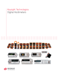
4.1.1 Two Wire Multiplexing
In the TwoWire multiplexed configuration, the SM4000 family first opens all channels, then it connects the Hi and
Lo terminals of the selected channel, to the Hi and Lo terminals of the A-bus. The SM4020 and SM4022 route Ch1
through Ch20, and the SM2040 and SM2042 can route Ch1 to Ch40 to the A-bus. Selecting Ch1 will result in
Ch1Hi connected to A-bus Hi and Ch1Lo connected to A-bus Lo.
When making very low level DCV measurements (<1 mV), you should use copper wires. A common source of
error can come from your test leads, which can introduce tens or hundreds of µVolts of error due to thermal
voltages (Thermal EMF or TEMF). To minimize thermo-voltaic effects, after handling the test leads, wait a while
for lead and terminal temperatures to equalize before attempting to make measurements. Signametrics offers
several high quality probes that are optimal for low level measurements. It is essential to select the right scanner for
the job. Make sure the relay scanner selected has sufficiently low thermal EMF (offset) specification. The SM4022
and SM4042 are the best choices for low level voltage measurements, as well as for Ohms and temperature. It is not
unusual to find scanners with very high thermal voltages. The following table quantifies the effect of Thermal
TEMF on Ohms measurement in a typical DMM such as the SM2042. This holds for both, 2-Wire and 4-Wire
Ohms measurement:
SM2042
Range
33 Ω
330 Ω
3.3 kΩ
33 kΩ
330 kΩ
3.3 MΩ
33 MΩ
Ohms
Current
10 mA
1 mA
1 mA
100 uA
10 uA
1 uA
100 nA
DMM
Resolution
10 µΩ
100 µΩ
1 mΩ
10 mΩ
100 mΩ
1Ω
100 Ω
Error due to
1uV TEMF
100 µΩ
1 mΩ
1 mΩ
10 mΩ
100 mΩ
1Ω
10 Ω
Error due to
10uV TEMF
1 mΩ
10 mΩ
10 mΩ
100 mΩ
1Ω
10 Ω
100 Ω
Error due to
100uV TEMF
10 mΩ
100 mΩ
100 mΩ
1Ω
10 Ω
100 Ω
1 kΩ
Table 4-1. The Scanner thermal EMF affect on Ohms measurement accuracy.
Figure 4-1. 40 Channel 2-Wire measurement application.
4.1.2 Four Wire Multiplexing
In the FourWire configuration, the SM4000 family connects simultaneously two channels. The SM4020 and
SM4022 route Ch1 through Ch10 to the A-bus, and the corresponding channels, Ch11 through Ch20, to the B-bus.
The SM4040 and SM4042 route Ch1 through Ch20 to the A-bus, and the corresponding channels, Ch21 through
Ch40 to the C-bus. To measure a resistor using Kelvin connection, the A-bus can be connected to the DMM source
leads and the B-bus to the sense leads. Make sure the polarity of the lines is consistent.
Signametrics
16
Figure 4-2. To perform 4-Wire resistance measurement with the SM4042, connect Ch1 and Ch21 to a resistor,
maintaining correct polarity.
4.1.3 Six Wire Multiplexing
In SixWire configuration, the SM4040 and SM4042 simultaneously connect one channel to the A-bus, one to the Bbus and one to the C-bus. Selecting a channel automatically closes three channel relays. For instance, selecting
channel 2 results in the opening of all currently closed channel relays, followed by the closure of Ch2, Ch12, and
Ch22. Each is routed to the A-bus, B-bus, and C-bus, respectively. To measure a resistor using 6-Wire guarded
connection, the A-bus is connected to the DMM source leads, the B-bus to the sense leads and the C-bus to the
Guarded point. Make sure the polarity of the lines is consistent. It should e noted that the ‘D’ group, consisting of
Ch31 to Ch40, is available independently to provide additional 10 channels of 2-Wire multiplexing.
Figure 4-3. In the 6-Wire configuration, the three lead sets are switched simultaneously.
4.1.4 Two Groups Configuration
In the TwoGroup configuration, the SM4000 family provides two independent multiplexing groups. Both groups
function as two independent two wire multiplexers. When a channel is selected, any closed channel within that
group is opened; next, the selected channel is closed. The SM4020 and SM4022 route Ch1 through Ch10 to the A-
17
Signametrics
bus, forming one group, and, Ch11 through Ch20 to the B-bus, forming the second group. The SM4040 and
SM4042 route Ch1 to Ch20 to the A-bus forming the first group, and Ch21 through Ch40 to the C-bus, forming the
second group.
4.1.5 Four Groups Configuration
In the FourGroup configuration, the SM4040 and SM4042 provide four independent multiplexing groups. The
groups function as independent two wire multiplexers. When a channel is selected, any closed channel within the
selected group is opened, followed by the closure of the selected channel. It’s like having four individual switching
modules. Ch1 to Ch10 are routed to the A-bus forming the first group. Ch11 to Ch20 are routed to the B-bus
forming the second group. Ch21 to Ch30 are routed to the C-bus forming the third group. Ch31 through Ch40 are
routed to the D-bus to form the fourth group.
Figure 4-4. In the Four Groups configuration, four independent 2-Wire scanners are available.
4.1.6 Disabled
In the Disabled configuration, all relays, including channel and configuration relays are open. This is the default
configuration, selected on power up, or initialization.
4.2 Scanner Operations
In addition to basic scanner operations such as selecting channels, the SM4000 series has several built-in operations,
which it more versatile and a lot more capable. These operations include various self-diagnostics procedures,
contact cleaning, and auto scanning and interfacing to external test and measurement instruments.
4.2.1 Trigger Output
The trigger output line, TRIG_out, maybe enabled or disabled as well as set for a positive or negative polarity
using the SCANTriggerOutState() command. Under normal operation, the TRIG_out line is active for the
duration of the Actuation time. It maybe used to drive or synchronize other test equipment. If set to positive
polarity, a positive edge indicates the selected channel is closed and settled, provided the correct Actuation time is
set (use SCANSetActuationTime() function to set it). The logic level of TRIG_out may be set high or low using
Signametrics
18
the SCANSetTriggerOut() function. In the following diagram, TRIG_out level corresponds to the circuit in figure
3.3.
Figure 4-4. The trigger input maybe set for polarity and be enabled or disabled.
4.2.2 Trigger Input
The trigger input line, TRIG_in, maybe set for a positive or negative polarity using the SCANTriggerInState()
command. Under normal operation, the TRIG_in line has no effect on the operation of the scanner. It maybe used
to synchronize other test equipment such as in the Triggered Auto Scan and Triggered Scan, where an external
event initiates scanning operation. The level of the TRIG_in line maybe monitored using the
SCANGetTriggerIn() command.
4.2.3 Auto Scan Operation
This operation requires that the Scanner be in one of the following configurations: TwoWire, FourWire, SixWire,
TwoGroups, or FourGroups. The Auto Scan operation is a software initiated Scan sequence. Issuing
SCANAutoScan() command triggers an automatic scanning operation, in which the first channel from the first
location in the Scan List table is selected first, followed by a delay equal to t-Step. Channels are selected
sequentially from the Scan List. The total number of points in the scan is controlled by the iPoints parameter passed
by the SCANAutoScan() function, which must be a value between 1 and 192. This mode maybe terminated by
sending SCANAbort() command to the Scanner during the scan. Use the SCANOpenAllChannel() function at the
end of the scan, if you wish to open the last selected channel. The Trigger output signal can be used to synchronize
other instruments to the SM4000 Scanner. The value of t-Step and t-Actuation can be set to generate a trigger output
signal for triggering instruments. For instance, setting the TRIG_out polarity to positive sense (as in Figure 4-6) will
result in a positive edge to trigger an SM2044 DMM, after a channel relay is closed and settled.
Figure 4-6. AutoScan is a software-initiated channel scanning procedure.
4.2.4 Triggered Auto Scan Operation
This operation requires that the Scanner be in one of the following configurations: TwoWire, FourWire, SixWire,
TwoGroups, and FourGroups. The Triggered Auto Scan operation is a hardware-triggered version of the above
Auto Scan operation. The trigger polarity can be selected. The SCANTrigAutoScan() function sets the Scanner
into the Triggered Auto Scan mode, in which the Scanner waits for a trigger edge to initiate an Auto Scan operation.
Once a trigger is received, the first channel from the first location in the Scan List table is selected, followed by a
delay equal to t-Step, then the selection of subsequent channels as specified in the Scan List table. The Scanner
proceeds to sequentially select a total of iPoints. The last parameter is passed to the scanner by the
SCANTrigAutoScan() function. This value must be between 1 and 192. This may be terminated by sending
19
Signametrics
SCANAbort() command to the Scanner. Use the SCANOpenAllChannel() function if you wish to open the last
selected channel at the end of the scan.
Figure 4-7. Positive edge Triggered AutoScan is a hardware initiated automatic scanning process.
4.2.5 Triggered Scan Operation
This operation requires that the Scanner be in one of the following configurations: TwoWire, FourWire, SixWire,
TwoGroups, and FourGroups. The Triggered Scan operation is a hardware driven scanning process. Each step
through the Scan List table is initiated by hardware trigger event. The trigger input signal edge polarity can be
selected. The SCANTrigScan() function sets the Scanner into the Triggered Scan mode, in which the Scanner
expects a total of iPoints triggers. Once this command is issued to the Scanner, it waits for the first trigger edge to
select the first channel from the first location in the Scan List table. Following the selection of each point, the
Scanner waits for t-Actuation period, during which triggers are ignored. The Scanner responds to subsequent trigger
edges by sequentially selecting channels stored in the Scan List. The total number of points in the scan is controlled
by the iPoints parameter passed to the scanner by the SCANTrigScan() function, which must be a value between 1
and 192. This mode is concluded at the end of the number of points specified, or terminated by sending
SCANAbort() command to the Scanner. Use the SCANOpenAllChannel() function if you wish to open the last
selected channel.
Figure 4-8. Positive edge Triggered Scan operation is a hardware initiated scanning process.
4.2.6 Single Step Scan Operation
This operation requires that the Scanner be in one of the following configurations: TwoWire, FourWire, SixWire,
TwoGroups, and FourGroups. The Single Step Scan operation is similar to the Triggered Scan process with the
exception that each step through the Scan List table is initiated by the SCANStep() command rather than by
hardware trigger event. The SCANSetupStep() function prepares the Scanner for this operation by resetting the
Scanner’s Scan List pointer to point to the first entry of the table. In response to the SCANStep() command, the
Scanner selects the channel stored in the Scan List location pointed to by the Scan List pointer, then it increments
this pointer to point to the next location. The number of points in the scan is controlled by the number of times
SCANStep() commands is issues since the last SCANSetupStep() function was executed. When done using the
SCANStep() and SCANSetupStep() functions, the Scanner is going to remain with the last channel selected. The
maximum number of entries in the Scan List is 192. The polled version of SCANStep(), SCANStepCmd() function
maybe used if a polled control is required. Read about the usage of polled operations in the “Polled Type
Operations” section. Use the SCANOpenAllChannel() function if you wish to open the last selected channel.
Signametrics
20
Figure 4-9. Single Step operation requires a SCANSetupStep() then SCANStep() command.
4.2.7 Scan List Operations
The Scan List table resides on board the scanner. It contains 192 locations, allowing a scan made up of up to 192
channels. Two DLL functions provide means to write and read to this table. The table contains channel numbers
associated with the scanner channels. The SM4040 and SM4042 may contain entries with values between 1 and 40,
representing the available channel numbers. An entry of zero forces deselection of all channels. The Scan List table
may contain repetition, or a scan sequence with multiple selection of a single channel. Entries to the table are
context sensitive. The current configuration of the Scanner determines how channels numbers are treated. For
instance, an entry of 40 is not reasonable while in FourWire configuration. In this configuration, an entry of 1
(Channel 1) will force selection of two channels, Ch1 and Ch21.
All Auto Scan operations read the table sequentially, starting at address 0 and ending at 191. It is important to
consider the configuration of the Scanner when setting the table. The table may be written and read any time the
Scanner is not busy. Operations using the Scan List include: SCANAutoScan(), SCANSetupStep(), SCANStep(),
SCANStepCmd() and SCANTrigAutoScan().
When several Scanners are connected to form a larger channel count, a zero entry disables al cards which are not
selected, while a valid channel values selects that channel of the active card. This way the scan can be made up of
channels from multiple Scanners. This requires that all Scanners included in the scan are loaded with the appropriate
table values. The following table shows a typical multiple card scanning operation, assuming all Scanners are in
TwoWire configuration.
Scanner
Number
SM4042 #0
SM4042 #1
SM4042 #2
Scanner#,
Channel
@0
@1
@2
0
3
0
#1,Ch3
0
40
0
#1,Ch40
8
0
0
#0,Ch8
Scan Table Entries
@3
@4
0
18
0
#1,Ch18
0
0
4
#2,Ch4
@5
@6
@7
0
0
5
#2,5
0
0
6
#2,6
1
0
0
#0,1
Figure 4-10. Contents of the Scan List table control Auto Scan sequence.
Use the SCANSetScanList() function to write to the Scanner hardware a channel value and SCANGetScanList()
to read a value.
4.2.8 Locating Shorted Channel
The SCANGetShortedChannel() function scans all channels, and returns the first channel which is shorted. This
can be used to detect a channel to see if it is the appropriate one, be it at the scanner input connector or at the
optional terminal block. It is particularly useful in locating and identifying channel connection at the application end
of a wiring harness.
21
Signametrics
4.2.9 Cleaning Relays Contacts
Using the SCANCleanRelays() function, the Scanner can clean each relay contact. It does this using a specially
designed on-board stimulus source along with a series of vibrations. This operation causes deposits of contaminants
such as polymer deposits as well as oxides to be removed. It also solves a common relay problem involving thin
film of insolationg deposits, which accumualte particularly on relays which have not been used for a while. It does
this by pinching through this film using an on-board high voltage souce. Performing this function on a regular basis
will improve the scanning system’s reliability and repeatability,as well as prolong contact life. All relays including
Channel relays, Configuration relays and Treeing relays are cleaned by this function. The test connector must be in
place in order to perform this operation. This function returns an error if the test connector is abscent. Cleaning
takes about 13 seconds for the SM404X and a bit less for the SM402X
4.2.10 Integrity Test
The Integrity test is a quick verification tool. The SCANTestChanIntegrity() function tests the integrity of the
specified channel relay, by verifying that the currently set actuation and release times are adequate. The release time
is assumed to be 1/2 of the actuation time. This procedure closes the relay, waits for a time equal to the actuation
time, then it tests for contact closure on both contacts. Next it opens the channel relay, waits for a period equal to
the release time, and verifies that the relay is open.
This test does not include bounce test. Use the SCANTestChannelRelay() and CANTestConfigRelay() functions
for a more comprehensive test. This test does not verify bounce
The test connector must be present in order to carry this operation. If the test connector is not present, this function
returns an error. Cleaning takes about 13 seconds for the SM404X and a bit less for the SM402X
4.2.11 Self Tests
These comprehensive tests consist of the Channel Relays test and the Configuration Relays test. They provide the
confidence of knowing that the Scanner is in good repair, and can continue in its operation. The two tests are
applied to a single channel: configuration or tree relay. These tests diagnose excessive bounce, open failure, and
short failure. If no failure is detected, these functions measure and return the actuation time for the selected relay.
The actuation time measured includes closure time plus bounce time. The results of these tests can be used to fine
tune the scanner for maximum switching time performance by either, setting the highest relay’s actuation time
(using the SCANSetActuationTime() function), or setting individual actuation time prior to selecting each channel.
The value of the measured actuation time is an indicative of the condition of the selected relay. A value higher than
that specified for the Scanner is an indication of relay deterioration, which may require relay replacement. These
tests require the test connector.
Channel Relays Test
Each Channel may be tested using the SCANTestChannelRelay() function. The Channel parameter can be a value
between 1 and 40 for the SM4040 and SM4042, and 1 to 20 for the SM4020 and SM4022. If no failure is detected,
this function returns the Actuation time for the relay.
Configuration Relays Test
Each Configuration and Tree relay may be tested using the SCANTestConfigRelay() function. Configuration relay
can be AtoA, BtoA, BtoB, CtoA, CtoC, DtoA, DtoC, or DtoD for the SM4040 and SM4042. For the SM4020,
SM4022 it can be AtoA, BtoA, or BtoB. See the ScanUser.H file for definitions of these relays. . If no failure is
detected, this function returns the Actuation time for the relay.
4.2.12 Setting Actuation Time Parameter
The Actuation time includes the time a relay closes and settles. It is made up of both, the Operate time and Bounce
time. Each relay has different actuation time, and therefore it is a good idea to keep the default 10ms Actuation time.
Alternatively, one can measure all relays, and set the Actuation time to the slowest relay of the Scanner. Actuation
time may vary with age, and could be an indication of fatigue of the relay. Configuration and Tree relays may be
Signametrics
22
measured using the SCANTestConfigRelay() function and the channel relays using the
SCANTestChannelRelay() function. Set the Actuation time using SCANSetActuationTime () and read it with
the SCANGetActuationTime() function. The SM4000 family of Scanners have a special active Release (drop-out
time) circuit, which forces all relays to release much faster than operate. For this reason, the Actuation time also
includes the release of a currently closed channel, in a break before make multiplexing. In configurations such as
the TwoWire, FourWire, SixWire, TwoGroups, and FourGroups, the Actuation time includes both the release and
operate processes. When enabled, the trigger output signal corresponds to the Actuation time. The trigger polarity
may be set positive or negative to provide means for triggering external devices when the switching is settled.
Further, the Actuation time maybe set to a value higher than necessary for relay actuation to provide delayed trigger.
Actuation time may be set to a value between 1ms to 850ms.
4.2.13 Setting Step Time Parameter
This parameter is the Auto Scan period, or step time. It maybe set to a value between 1ms to 850ms. On power up, it
defaults to 100ms. It is the channel to channel scan time in Auto Scan. Use SCANSetStepTime() to set it and
SCANGetStepTime() to read it. When enabled during Auto Scan, the trigger output signal will have a period equal
to the Step Time, and depending on trigger polarity, a negative or positive pulse corresponding to the Actuation
time. The trigger can be used to provide means for triggering external devices with the desired delay. For example,
consider a case where the Actuation time has been set to 50ms, but the relays actually settle within 10ms. In this
scenario, additionally consider a Step time that has been left at its default value of 100ms, along with a trigger
output that has been enabled and set for positive sense. With these parameters, the rising edge of the trigger output
is delayed by 40ms (50ms – 10ms) from the time the relays are closed and settled, and the scanning speed is 10
channels per second (1/100ms).
Figure 4-11. Step Time and Actuation Time parameters relations.
4.2.14 Thermocouple Temperature Measurements
With the active Isothermal terminal block option, it is possible to measure temperture using
thermocouples. The active Isothermal block has a temperature sensor on the board, which can be
measured using the Signametrics SM2040 series DMM with Thermocouple option. Several additional
measurement functions included with this option allow both, reference junction temperature measurement
and linearization of several common Thermocouple types. The junction temperature is measured by
setting the Scanner to the Universal configuration and closing the AtoA DtoA and DtoD relays. This
allows the measurement of the D-bus, which is connected, on the terminal block, to the temperature
sensor of the active isothermal terminal block.
4.3 Polled Type Operations
Since the Scanner has it’s own controller, it is capable of processing operations, such as selecting a channels or
executing a long test procedure, without help from the PC. For instance, when the SCANSelectChannel() function
is issued, the DLL waits for the completion of the operation. It actually waits for the Scanner to complete the
operation. In response to the command the Scanner opens the appropriate channels, closes the selected channel, and
then waits for Actuation time prior to responding with ‘operation complete’ to the PC (DLL). When using the
polled version of the above command, SCANSelectChannelCmd(), no waiting takes place. The command is sent
to the Scanner and the PC (DLL) does not wait for response. A test program may take advantage of this. It can issue
the polled command, then perform various other tasks, such as setting a DMM range, then check the Scanner for
completion of the polled command by using SCANReady(). When the last command returns TRUE, it means that
23
Signametrics
the Scanner is ready to accept a new command, and in the case of channel selection, the selected channel is closed
and settled. If SCANReady() returns TRUE, it should not be used again until the next polled command is issued.
The following is a list of all polled functions: SCANSelectChannelCmd(), SCANAutoScan(),
SCANTrigAutoScan(), SCANTrigScan(), SCANStepCmd() and SCANCleanRelays().
4.4 Interfacing to the SM2040 series 6-1/2 Digit DMM
The SM4000 series Scanners are designed to interface to the SM2040, SM2042, and SM2044 Digital
Multimeters. The following section describes both, the hardware interface and the software functions used
to implement a synchronized operation.
4.4.1 Triggering the SM2040 DMMs
The SM2040, SM2042, and SM2044 can be triggered to measure selected Scanner channels. The
interface requires a single jumper between the SM4000 Trig_com and Common lines, and two interface
wires connected to the SM2040 series Trigger input. Once connected, the Scanner can be setup to
produce a trigger signal for each relay selection operation. The various auto scanning operations can run
independently from the computer, whereby the Scanner selects a list of channels stored in its Scan List
table, and the DMM is triggered to take measurements following each channel selection.
Figure 4-12. Trigger interfacing connection to an SM2040 class of DMMs.
4.4.2 Multiplexing with the SM2040 DMMs
For two wire measurements, the SM204X DMMs must be connected to the A-Bus or the scanner, or to both, the ABus and C-Bus for 4-Wire measurements (SM4040, SM4042). It is important to consider system-settling time when
making measurements. Time delays exist in any measurement system. These delays are contributed by various
sources. These include the relay Actuation times, the DMM input settling and wiring burden. The latter is primarily
due to capacitance, and will vary with the type of measurement. For instance, when making high value Ohms
measurements the DMM current source level could contribute significant delay due to the capacitance charge time.
For example, with 1,000pf cable capacitance, the source current of the SM2044 DMM using the 33MΩ range, is
0.1µA which translates to 33ms (dt = C*dV/I). It is also recommended to set the appropriate number of settling
measurements for the DMM (a minimum of 4 is recommended).
4.4.3 Interface Commands and Timing
The sequence required for the SM2040 DMM to make triggered measurements that are generated by the SM4040,
starts with the preparation of the SM4040. Set the SM4040 desired configuration, with Trigger Output enabled and
positive polarity. Each channel selection will generate a positive pulse with a duration equal to the Actuation time.
This could be generated by one of the scanning operations, or simply by sending channel selection commands to the
SM4040. The SM2040 must also be set up for triggered readings by using the DMMSetTrigRead() command. In
the following example, the SM2040 must send readings during the scan. Since it’s on board Fifo is limited to 5
readings, and the DMM must continue to send all readings during the scan, it is important to have a tight loop that
reads the measurements fast enough. Refer to Figure 4-12 for proper trigger connection.
Signametrics
24
SCANTriggerOutState(iScan, Enabled, PosEdge)
‘ Set trigger output to Positive edge.
iReadings = 10
‘ Total number of measurements to take
DMMSetTrigRead(iDmm, 4, iReadings, NegEdge)
‘ Total of 10 readings and 4 settling readings each
SCANAutoScan(iScan, iSteps)
‘ Start auto scan
For I = 0 to iReadings -1
‘ read measurements as they come
While DMMReadTrigVal(iDmm, reading) = NO ‘ wait for each reading and store it
DoEvents
Wend
Next
SCANOpenAllChannels(iScan)
‘ Good idea to open all channels when done
Figure 4-13. Triggered reading process and timing of SM4042 Scanner and SM2044 DMMs.
Unlike the previous example, DMMSetBuffTrigRead() is not time critical since the DMM saves all
measurements to it’s on-board buffer, which is read after the scan is complete.
SCANTriggerOutState(iScan, Enabled, PosEdge)
‘ Set trigger output to Positive edge.
iReadings = 50
‘ Total number of measurements to take
DMMSetBuffTrigRead(iDmm, 4, iReadings, NegEdge)
‘ Use 4 settling readings each
SCANAutoScan(iScan, iSteps)
‘ Set off AutoScan
While DMMReady(iDmm) = NO
‘ wait for the DMM to indicate capture
Wend
‘ completion of iReadings (available In buffer)
For I = 0 to iReadings -1
‘ read values stored in the buffer
DMMReadBuffer(iDmm, Buffer(I) )
‘ Store each reading
Next
SCANOpenAllChannels(iScan)
‘ Good idea to open all channels when done
While SCANReady(iScan) = NO
‘ Since AutoScan is a polled operation,
DoEvents
' Make sure Scanner is ready
Wend
There are several SM2040 family commands to considered for this operation: DMMSetTrigRead(),
DMMSetBuffTrigRead(), DMMReadTrigVal(), DMMReady(), DMMReadBuffer() and
DMMReadBufferStr(). Do not forget to open all channels at the end of the scan, using
SCANOpenAllChannels().
Referring to figure 4.13, it is clear that the total time the DMM takes reading must be kept shorter
than t-Delay (t-Step – t-Actuation), for completion of the measurements prior to the selection of the
next channel. That means that t-Step must be greater than t-Actuation + (nSettling + 1) / (read. per
sec.)
4.5 Single Ended application Example
4.5.1 Point to Point Configuration
This may not be obvious, but the SM4040 and SM4042 can be used for single ended applications.
Taking advantage of the Universal mode, a point to point switching can be implemented. Such
application includes loaded board test commonly used by MDAs. The 40 differntial inputs to the
multiplexer become 80 independent lines (Ch1Hi, Ch1,Lo, Ch2Hi, Ch2Lo, ... CH40Hi, Ch40Lo)
which can be connected to one of the four busses, A, B, C and D. These in turn can be connected to
an instuments such as the SM2044 DMM. Further, it is also possible to configure it in such a way that
the selected line can may be connected to either the positive or the negative terminal of the DMM.
Using multiple SM4042 a high point test system can be constructed. In the following example, the
Vlow of the DMM is connected to the Bhi and the Dlo line of the SM4042. The Vhigh of the DMM
25
Signametrics
is connected to the Ahi and Clo of the SM4042. The next table provide the setting for a few singleended connections to examplify this application.
Closed
channel relay
Ch1
Ch40
Ch1
Ch40
Ch1
Ch40
Ch1
Ch40
Ch1, Ch40
Ch1
Ch1
Closed Bus relay
A-to-A
A-to-A
C-to-C
C-to-C
B-to-B
B-to-B
D-to-D
D-to-D
A-to-A ,D-to-D
A-to-A, D-to-D,
C-to-C, B-to-B
Closed
Cofiguration relay
D-to-A
C-to-A
D-to-C
B-to-A
D-to-A, B-to-A
D-to-A
D-to-A
C-to-A, B-to-A
DMM Low
terminal
Ch1Hi
Ch40Hi
Ch1Lo
Ch40Lo
Ch40Lo
Ch1Lo
Ch1Hi
DMM High
terminal
Ch1Hi
Ch40Hi
Ch1Lo
Ch40Lo
Ch1Hi
Ch1Hi
Ch1Lo
4.5.2 An 84 Point, Single End Configuration
By connecting AHi (pin 30B) and CLo (pin 30C) we can create an 84 single ended selector switch.
The collector of this switch is pin 30B (Figure 4-14). Ch1 corresponds to Ch1Hi, Ch2 to Ch2Hi
…Ch10 is Ch10Hi etc.. Using Universal mode, make sure to select both, the appropriate channel
relay as well as the various configuration relays.
Figure 4-14. Single point switching is enabled by connecting A-bus High and C-bus Low.
5.0 SM4040 Scanner Family Windows Interface
The windows release supports Windows98®, Windows95®, WinNT4.0®, and Windows2000®. The
primary means of controlling the scanners is a .DLL file that interfaces with the PCI bus via a .VXD
file for Windows98/95 or .SYS driver for WinNT4.0® or Windows2000®. All of these components
are placed at the appropriate directories, and registry entries are made during Setup.
5.1 Distribution Files
The main directory of the distribution diskette contains the Microsoft® Windows™ SM4040 Scanner
software. To install this software, enter the command "A:SETUP" in the "Run Program" menu of the
Windows File Manager; or double-click on the SETUP.EXE file name from the File Explorer Tool
Manager window. Most files on this diskette are compressed, and must be installed using the SETUP
program.
The SM4040 DLL is a protected-mode Microsoft® Windows™ DLL that will control the
Signametrics SM4020, SM4022, SM4040, and SM4042. It is provided with a sample Visual Basic™
control-panel application (GUI) to demonstrate the Scanner and the interface to the DLL. Check the
README.TXT file for more information about the files contained on the diskette. Some important
files to note are:
Signametrics
26
File
Description
SM4040.LIB
The Windows import library. Install in a directory pointed to by your
LIB environment variable.
SM4040.DEF
SM2040 driver DLL module definition file.
SM4040.DLL
The 32 bit driver DLL. This should be installed either in your working
directory, in the Windows system directory, or in a directory on your
PATH. The installation program installs this file in your Windows
system directory (usually C:\WINDOWS\SYSTEM for Win98/95 or
at C:\WINNT\SYSTEM32 for Windows NT).
SM4040.H
Driver header file. Contains the definitions of all the Scanner’s
function prototypes for the DLL, constant definitions, and error codes.
Install in a directory pointed to by your INCLUDE environment
variable.
ScanUser.H
Header file containing all of the necessary Scanner’s function
parameters and configuration definitions to be used with the various
functions.
Msvbvm50.dll
Visual Basic run-time interpreter. Usually, install in your
C:\WINDOWS\SYSTEM (or equivalent) directory. If it is not already
installed, run Msvbvm50.exe for proper extraction and registration.
SM4044.vbw
Visual Basic project file
SM4044.frx
Visual Basic binary form file
SM4044.frm
Visual Basic file with main form
SM4044.vbp
Visual Basic project file
2044glbl.bas
Visual Basic file with all global Scanner declarations
File
Description
SM4044.exe
Visual Basic Scanner control panel executable
Msvcrt.dll
System file. Installs in your C:\WINDOWS\SYSTEM directory.
Windrvr.vxd
Win98/95 Virtual Device Driver. Installs in your
C:\WINDOWS\SYSTEM\VMM32 directory.
Windrvr.sys
Win NT/Win 2000 Virtual Device Driver. Installs in your
C:\WINNT\SYSTEM32\DRIVERS directory.
Install.doc
Installation instructions in MS Word
During initialization (SCANInit()), the driver reads various parameters such as Scanner type (SM4020/22/40/42),
and serial number etc..
5.2 Using the SM4040 Driver with C++ or Similar Software
27
Signametrics
Install the SM4040.H and ScanUser.H header files in a directory that will be searched by your C/C++ compiler for
header files. These header files are known to work with Microsoft Visual C++™.To compile using Borland, you
will need to convert the SM4040.DEF and SM4040.LIB using ImpDef.exe and ImpLib.exe, provided with the
compiler. Install SM4040.LIB in a directory that will be searched by the linker for import libraries. The SM2040
software must be installed prior to running any executable code. Install the SM4040.DLL in a location where either
your program will do a LoadLibrary call to load it, or on the PATH so that Windows will load the DLL
automatically. A common place for the DLL is at C:\WINDOWS\SYSTEM directory for Win98/95 or at
C:\WINNT\SYSTEM32 directory for NT and Windows 2000.
In using the SM4040 driver, first call SCANInit to initialize the scanner hardware and software. This function
should only be used once. Call SCANSetConfig to set the Scanner to a desired configuration, be it TwoWire,
FourWire etc. The Scanner function constants are defined in the ScanUser.H header file, and have names that
clearly indicate the function they invoke.
Two functions are provided to set channel-relays, SCANSelectChannel and SCANSetChannelRelay. The first
opens all channels in a group, and closes the specified channel. The second function is usable while the scanner is in
the Universal configuration, and opens or closes a specified channel relay,.
Most functions accept a Scanner number parameter, which must be set to the iScan value when initializing the
scanner with the SCANInit. For multiple Scanners this iScan value will be 0,1,2..n. Most functions return an error
code that can be retrieved as a string using SCANErrStr.
5.2.1 Multiple Card Operations under Windows
Single .EXE operation
Accessing multiple Scanners from a single executable is the most common way for running up to 10 Scanners using
the Windows DLL. A combination of several SM404X can be controlled, as long as the single .EXE (Thread) is
used to control all of the units. Make sure that prior to issuing commands to any Scanner, it is initialized using
SCANInit. The iScan parameter is passed with each DLL command to define the unit to be accessed. Since this
configuration utilizes the DLL to service all units, it must handle one command at a time. For example, when one
Scanner’s channel is selected (with a non polled command the DLL must finish the operation prior to addressing
another Scanner. For improved performance, one can use the following:
Multiple .EXE operation
By having several copies of SM4040.DLL, and renaming them, you may multiple Scanners with separate
executables. For instance, having a copy named SM4040A.DLL and one named SM4040B.DLL in
C:\WINDOWS\SYSTEM (Win98/95), and having two executable files, MultiExeA.exe and MultiExeB.exe, each
of the executables will run independently, making calls to the respective DLL. This can provide an execution
throughput advantage over the method mentioned above. If using VisualBasic, the MultiExeA.exe source code
should define iScan = 0, and MultiExeB.exe should define iScan = 1. In addition, the first EXE should declare the
SM4040A.DLL and the second should declare SM4040B.DLL:
/***********************************************************************
* Exmp4040.C Exmp4040.EXE
*
* A simple Windows .EXE example for demonstrating the SM4040
* Scanners using "C"
* Sets Configuration to TwoWire, and select a channel.
*
***********************************************************************
* Make sure SM4040.lib is included in the libraries. For Microsoft
* Version 4.0 C++ and above, place under 'Source Files' in the
* Workspace, along side with Exmp4040.c
* PROJECT SETTINGS:
*
* /nologo /ML /W3 /GX /O2 /D "WIN32" /D "NDEBUG" /D "_CONSOLE" /D "_MBCS"
* /FR"Release/" /Fp"Release/Exmp4040.pch" /YX /Fo"Release/" /Fd"Release/" /FD /c
Signametrics
28
*
* Copy both SM4040.DLL and SM4040.LIB to the project directory.
*
***********************************************************************/
// #define WINAPI __stdcall
#include <windows.h>
#include <string.h>
#ifdef _Windows
#define _WINDOWS
#endif
#include “SM4040.H”
// functions declarations and error codes.
#include “ScanUser.H”
// All functions, range and rate info and function declarations.
int main(void){
int I, iScan = 0;
// Address first Scanner in the system
char Read[16];
char strMsg[256];
i = SCANInit(iScan");
// initialize SM4040
if(i<0)
MessageBox(0,"Initialization ERROR !", "Startup SM4040 DLL",MB_OK);
// Show Error
SCANSetConfig(iScan,TwoWire);
// Set to TwoWire configuration
SCANSelectChannel(iScan,32);
// Close Channel 32 relay, and necessary path relays
MessageBox(0,strMsg, "Channel 32 is closed and settled",MB_OK);
// Show status
return 0L;
5.3 Visual Basic Front Panel Application
The Visual Basic front panel application, SM4040.EXE, is an interactive control panel for the SM4040 Scanners.
When it loads it will take a few seconds to initialize before the front panel is displayed.
The push buttons labeled and menus provide means to configure the Scanner and select channels. The panel has
several capabilities which are enabled and disabled according to the type of Scanner detected, and the current
configuration.
The source code file GLOBAL.BAS (in the installed VisBasic sub directory) contains the function declarations and
the various ranges, rates and other parameters that are required. These definitions are the duplicates of the “C”
header files required to write Visual Basic applications which interact with the driver DLL, along with some global
variables required for this particular front-panel application.
5.3.1 Visual Basic Simple Application
The following is a very simple panel application for VisualBasic, which is included with the installed software. The
two files, Global.Bas and SimplePanel.frm are presented here. This GUI panel contains six objects; a text box to
input channel to select, three option buttons to set configuration, a button to apply the channel selection and a text
line for displaying errors.
Global.bas module file contents:
Option Explicit
'function declarations
Declare Function SCANInit Lib "sm4040.dll" _
(ByVal nScanner As Long) As Long
Declare Function SCANSetConfig Lib "sm4040.dll" _
(ByVal nScanner As Long, ByVal Config As Long) As Long
Declare Function SCANErrString Lib "sm4040.dll" _
(ByVal nError As Long, ByVal errString As String, ByVal stringlen As Long) As Long
Declare Function SCANSelectChannel Lib "sm4040.dll" _
(ByVal nScanner As Long, ByVal nChannel As Long) As Long
'Configuration definitions for :
Global Const TwoWire = 0
Global Const FourWire = 7
29
Signametrics
Global Const SixWire = &H1E
' Since the DLL is written in "C", where TRUE = 1 and FALSE = 0
' and VB has -1 for True, use YES and NO instead of True and False
Global Const YES = 1
Global Const NO = 0
‘Error handling code:
Public Sub ShowFault(status As Long)
Dim errtext As String * 48
Dim errcode As Long
Dim start As Single
If status < 0 Then
errcode = SCANErrString(status, errtext, 48)
SimplePanel.TextLine.Text = errtext
If status <> -3 Then 'if not autorange wait with message
start = Timer
While ((Timer - start) < 2#) 'delay for 1.1 seconds
DoEvents
Wend
End If
SimplePanel.TextLine.Text = ""
End If
End Sub
SimplePanel.frm Form file contents:
Option Explicit
Private Sub CommandSelect_Click()
ShowFault SCANSelectChannel(0, Lng(TextChan.Text)) 'Select the channel
End Sub
Private Sub Form_Load()
Dim errtext As String * 64
Dim i, j, k As Long
i = SCANInit(0)
End Sub
'Initialize scanner 0
Private Sub Option2W_Click()
ShowFault SCANSetConfig(0, TwoWire)
End Sub
Private Sub Option4W_Click()
ShowFault SCANSetConfig(0, FourWire)
End Sub
Private Sub Option6W_Click()
ShowFault SCANSetConfig(0, SixWire)
End Sub
5.4 Windows DLL Default Modes and Parameters
Signametrics
30
After initialization, the Windows DLL default modes and parameters on your Scanner are set up as follows:
•
•
•
•
Configuration is set to Disabled
Trigger output is disabled
Actuation time is set to 10ms
Step time is set to 100ms
5.5 Using the SM4040 DLL with LabWindows/CVI®
When using the SM4040 DLL with LabWindows/CVI, you should read the LabWin.txt file included with the
software diskette.
NOTE: Although these measurement functions use LabWindows/CVI® and the LabWindows/CVI(R)
Test Executive, they are not necessarily coded to LabWindows® instrument driver standards.
5.6 Windows Command Language
The following section contains detailed descriptions of each function of the Windows command language. Those
commands that pertain to only the SM2040 are indicated. Most functions return an error code. The code can either
be retrieved as a string using SCANErrString() function, or it may be looked up in the SM4040.H header file.
SCANAbort
H/W access Command ; Polled Command ;
Description
Abort current operation.
#include "SM4040.h"
int SCANAbort(int iScan)
Remarks
This function aborts in process, polled function such as: SCANAutoScan(),
SCANTrigScan(), SCANTrigAutoScan() etc.. It terminates the current operation and
prepares the Scanner ready to accept a new command.
Parameter
Type/Description
iScan
int Identifies the Scanner. 0 for the first scanner.
Return Value
Example
The return value is one of the following constants.
Value
Meaning
SCAN_OKAY
Operation successfully terminated
Error code.
Negative value
SowFault(SCANAbrt(0));
// VisualBasic application
31
Signametrics
SCANAutoScan
H/W access Command ; Polled Command ;
Description
Initiate AutoScan operation.
#include “SM4040.H”
int SCANAutoScan(int iScan, int iPoints)
Remarks
Run Auto Scan procedure from the Scanner's stored ScanList. This operation is carried
out by the scanner’s on-board processor. It uses the Scan List table and timing
parameters to perform a complete scan sequence. If necessary, the scan may be
terminated by sending the SCANAbort() command. The Scanner scans iPoints of
consecutive locations from the ScanList, starting with the point stored in location 0, and
up to location 191 (max of 192 for iPoints). Steptime and Actuation time values must be
set prior to executing this function. The Scan List must contain channel information for
at least iPoints prior to using this command. Steptime must be greater than the Actuation
time. This function is not applicable for the following configurations: Universal and
Disabled.
Being a polled function, following this command uses SCANReady() to test for
completion of the operation. No new H/W access command should be issued prior to
SCANReady() return of TRUE. An exception is the SCANAbor() command which
terminates the current operation.. Following reception of this command, the Scanner
hardware enters a busy state. When SCANReady() returns TRUE do not use it again.
Parameter
Type/Description
iScan
int Identifies the Scanner. Scanners are numbered starting with zero.
iPoints
int The number of points in the scan. This number must be between 1
and 192, inclusive.
Return Value
Example
Signametrics
The return value is one of the following constants.
Value
Meaning
SCAN_OKAY
Operation successfully terminated
Negative Value
Error code.
i = SCANAutoScan(0,22); // Scan 22 points;
while(!SCANReady(0));
// Wait for completion of scan
32
SCANCleanRelays
H/W access Command ; Polled Command ;
Description
Clean all relays.
#include “SM4040.H”
int SCANCleanRelays(int iScan)
Remarks
This function Cleans all relays. The test connector must be present to clean all contacts.
This function verifies that the test connector is present. Cleaning takes about 13 seconds
for the SM404X and a bit less for the SM402X. Vibrating of the contacts at varying
switching patterns, while sourcing a high voltage/low current signal, causes deposits of
contaminants as well as oxidations to bounce off or be pinched through, thus resulting in
cleaner contacts. Doing this on a regular basis will prolong the contacts’ life. Both
Channel relays and Configuration relays are cleaned. Function type: Polled, requires
SCANReady() prior to using additional functions.
Parameter
Type/Description
iScan
int Identifies the Scanner. Scanners are numbered starting with zero.
Return Value
Example
The return value is one of the following constants.
Value
Meaning
SCAN_OKAY
Scanner is OK.
Negative Value
Error
SCANCleanRelays(0);
// Issue clean command
while( !SCANReady(0) ); // Wait for completion
33
Signametrics
SCANClosePCI
H/W access Command ; Polled Command ;
Description
Close the PCI bus for the specified Scanner. Not for user applications.
int SCANClosePCI(int nScan)
Remarks
This function is limited for servicing the Scanner. It has no use in normal operation. See
also SCANOpenPCI() function.
Parameter
Type/Description
nScan
int Identifies the Scanner number
Return Value
Integer error code.
Value
Meaning
SCAN_OKAY
Operation successfully completed.
Negative Value
Error code
Example
int status = SCANClosePCI(0);
SCANDelay
H/W access Command Polled Command
Description
Wait for a given time.
#include “SM4040.H”
int SCANDelay(double dTime)
Remarks
Delay of dTime seconds. dTime must be a positive double floating point number between
0.0 and 100.0 seconds.
Parameter
Type/Description
dTime
double Delay time in seconds.
Return Value
Example
Signametrics
The return value is one of the following constants.
Value
Meaning
SCAN_OKAY
Operation successfully terminated
Negative Value
Error code
SCANDelay(1.2); /* wait for 1.2 Sec */
34
SCANErrString
H/W access Command Polled Command
Description
Return the string describing the error.
#include “SM4040.H”
int SCANErrString(int iErrorCode, LPSTR lpszError, int iBuffLength)
Remarks
This function returns a string containing the error description, which corresponds to the
integer error, code iErrorCode. The error string is placed at lpszError.
Parameter
Type/Description
iErrorCode
int Error code.
iBuffLength
int The maximum available length of the string buffer
lpszError
LPSTR Points to a buffer (at least 40 characters long) to hold the
error string.
Return Value
Example
The return value is the length of the error string or one of the following constants.
Value
Meaning
Positive Value
Length of returned error string.
Negative Value
Error code
char cBuf[48];
int length = SCANErrString( -3, cBuf, 48);
35
Signametrics
SCANGetActuationTime
H/W access Command Polled Command
Description
Return the currently set actuation time.
#include “SM4040.H”
int SCANGetActuationTime(int iScan, double FAR *lpdAct)
Remarks
This function returns a double floating value that is the currently set relay actuation time
for the selected scanner.
Parameter
Type/Description
iScan
int Identifies the Scanner. Scanners are numbered starting with zero.
lpdAct
double FAR * Pointer where t-Actuation value is to be saved.
Return Value
Integer error code.
Value
Meaning
SCAN_OKAY
Operation successfully completed.
Negative Value
Error code
Example
double FAR tAct; int i = SCANGetActuationTime(0, &tAct);
SCANGetBusInfo
H/W access Command Polled Command
Description
Returns the PCI Bus and Slot numbers for the selected SCANNER.
int SCANGetBusInfo(int nScan, int *bus, int *slot)
Remarks
Return Value
Signametrics
This function reads the PCI bus and slot numbers for the selected Scanner. It provides
means to relate the physical location to the nScan value by detecting the location of a
Scanner in the PCI system tree. This function actually scans the hardware rather then
look up the information in the registry.
Parameter
Type/Description
nScan
int Identifies the Scanner. These are numbered starting with zero.
bus
int * a pointer to integer at which the bus number is stored (0 to 255)
slot
int * A pointer to an integer where the slot number is stored (0 to
15)
The return value is one of the following constants.
36
Value
Meaning
SCAN_OKAY
Operation was successful.
Negative number
Error code
Example
int bus, slot; // Find on which bus, and slot the DMM is at
SCANGetCalDate(3, &bus, &slot); // SCANNER#3
SCANGetConfig
H/W access Command ; Polled Command
Description
Read the current configuration of the scanner.
int SCANGetConfig(int iScan)
Remarks
This function reads the current configuration settings from the Scanner hardware. The
configurations are defined in the ScanUser.H file.
Parameter
Type/Description
IScan
int Identifies the Scanner. Scanners are numbered starting with zero.
Return Value
The return value is an integer configuration code or an error code
Value
Meaning
Positive Value
Configuration code
Negative Value
Error code
Example
int iConfig = SCANGetConfig(0);
SCANGetGrdVer
H/W access Command ; Polled Command
Description
Get Scanner firmware version.
#include “SM4040.H”
int SCANGetGrdVer(int iScan)
Remarks
This function reads and returns the Scanner’s firmware version, which is the on-board
Microcontroller’s S/W version. This integer should be divided by 10 to get the actual
version. i.e., 15 equals version 1.5.
Parameter
Type/Description
IScan
int Identifies the Scanner. Scanners are numbered starting with zero.
Return Value
Integer version value or an error code.
Value
Meaning
37
Signametrics
Positive Value
Version
Negative Value
Error code
Example
firmware_ver = SCANGetGrdVer(0);
SCANGetHwVer
H/W access Command Polled Command
Description
Get the hardware version of the Scanner.
#include “SM4040.H”
int SCANGetHwVer(int iScan)
Remarks
This function returns the Scanner hardware version. A returned value of 0 corresponds to
Rev_, 1 corresponds to Rev_A, 2 to Rev_B etc.
Parameter
Type/Description
iScan
int Identifies the Scanner. Scanners are numbered starting with zero.
Return Value
Scanner hardware code or an error code.
Value
Meaning
Positive value
Hardware version code
Negative Value
Error code
Example
int HWVer = SCANGetHwVer(0);
SCANGetID
H/W access Command Polled Command
Description
Get Scanner ID code.
#include “SM4040.H”
int SCANGetID(int iScan)
Remarks
This function returns the Scanner’s identification code. Each Scanner has a unique ID
code, which is part of the serial number.
Parameter
Type/Description
IScan
int Identifies the Scanner. Scanners are numbered starting
with zero.
Return Value
Integer card ID code (serial number) or an error code.
Value
Signametrics
Meaning
38
Positive Value
Scanner ID code
Negative Value
Error code
Example
int id = SCANGetID(0);
SCANGetManDate
H/W access Command Polled Command
Description
Get Manufacturing date stamp from the Scanner hardware
#include “SM4040.H”
int SCANGetManDate(int iScan, int *month, int *day, int *year)
Remarks
This function returns the Scanner’s manufacturing date, which is read from the hardware.
The month, day and year are returned as integers. This is used to track the Scanner to a
specific manufacturing date code.
Parameter
Type/Description
IScan
int Identifies the Scanner. Scanners are numbered starting
with zero.
Month
int * A pointer to an integer where the month is stored
Day
int * A pointer to an integer where the day is stored
Year
int * A pointer to an integer where the year is stored
Return Value
Example
Integer error code.
Value
Meaning
SCAN_OKAY
Operation was successful.
Negative Value
Error code
int month, day, year, status
status = SCANGetManDate(0, &month, &day, &year);
SCANGetScanList
H/W access Command ; Polled Command
Description
Get a value from the on-board Scan List table.
#include “SM4040.H”
int SCANGetScanList(int iScan, int iAddress)
Remarks
This function returns an integer value corresponding to the iAddress entry to the
Scanner’s on-board scan list. This value should be 0 to 40 corresponding to an open
channel or channel 1 to 40. This value is written to the table by SCANSetScanList().
Parameter
Type/Description
39
Signametrics
Iscan
int Identifies the Scanner. Scanners are numbered starting with zero.
LpdMax
double FAR * Pointer where the Max value is to be saved.
Return Value
Integer error code..
Value
Meaning
SCAN_OKAY
Operation successfully completed.
Negative Value
Error code
Example
int ScanLst[192];
ScanLst[3] = SCANGetScanList(0, 3);
//Get the 4th entry
SCANGetShortedChannel
H/W access Command ; Polled Command
Description
Returns the channel number of the shorted channel.
#include “SM4040.H”
int SCANGetShortedChannel(int iScan)
Remarks
This function searches and detects a shorted channel, starting with channel 1. It returns
the first channel which is found to be shorted. If none is found, the returned value is 0. A
valid returned value must be 0 to 40. 0 indicates no shorted channel is found, 1 to 40
correspond to channels 1 to 40 being shorted.
Parameter
Type/Description
iScan
int Identifies the Scanner. Scanners are numbered starting with zero.
Return Value
Example
The return value corresponding to the shorted channel or an error code.
Value
Meaning
0
No shorted channel found.
1 to 40
Shorted channel number
Negative Value
Error code
int shorted = SCANGetShortedChannel(0);
SCANGetStepTime
H/W access Command Polled Command
Description
Get the currently set Auto Scan step time.
#include “SM4040.H”
Signametrics
40
int SCANGetStepTime(int iScan, double FAR *lpdTstep)
Remarks
This function returns a double floating value that is the currently set step time.
Parameter
Type/Description
iScan
int Identifies the Scanner. Scanners are numbered starting with zero.
lpdTstep
double FAR * Pointer where the Step time value is to be saved.
Return Value
Integer error code..
Value
Meaning
SCAN_OKAY
Operation successfully completed.
Negative Value
Error code
Example
double FAR Tstep;
int status = SCANGetStepTime(0, &Tstep);
SCANGetTriggerIn
H/W access Command Polled Command
Description
Read the state of the Trigger Input line.
#include “SM4040.H”
int SCANGetTriggerIn(int iScan)
Remarks
This function returns the logic state of the Hardware trigger input line to the Scanner.
Parameter
Type/Description
iScan
int Identifies the Scanner. Scanners are numbered starting with zero.
Return Value
Example
Scanner hardware code or an error code.
Value
Meaning
0 or Positive value
State of the Trigger inut line.
Negative Value
Error code
int Trig = SCANGetTriggerIn(0);
SCANGetType
H/W access Command Polled Command
Description
Get the type of the Scanner.
#include “SM4040.H”
41
Signametrics
int SCANGetType(int iScan)
Remarks
This function returns the Scanner type.
Parameter
Type/Description
iScan
int Identifies the Scanner. Scanners are numbered starting with zero.
Return Value
Scanner type Integer or an error code.
Value
Meaning
4020
SM4020 is at iScan slot
4022
SM4022 is at iScan slot
4040
SM4040 is at iScan slot
4042
SM4042 is at iScan slot
Negative Value
Error code
Example
int type = SCANGetType(0);
SCANGetVer
H/W access Command Polled Command
Description
Return the Scanner’s DLL software driver version.
#include “SM4040.H”
int SCANGetVer(double FAR *lpfResult )
Remarks
This function returns the Scanner’s software driver version, which is a double floating
value.
Parameter
Type/Description
lpfResult
double FAR * Pointer to the location which holds the version.
Return Value
Integer value version code or an error code.
Value
Meaning
SCAN_OKAY
Operation successfully completed.
Negative Value
Error code
Example
int status; double d;
status = SCANGetVer(&d);
SCANInit
H/W access Command ; Polled Command
Signametrics
42
Description
Initialize the scanner.
#include "sm4040.h"
int SCANInit(int iScan)
Remarks
This function must be the first function to be executed. It opens the driver for the
specified Scanner. The first one being 0, the second 1, etc. It also initializes the hardware
and software and sets the scanner to Disabled configuration.
Parameter
Type/Description
iScan
int Identifies the Scanner. Scanners are numbered starting with zero.
Return Value
The return value is one of the following constants.
Value
Meaning
SCAN_OKAY
Scanner was initialized successfully.
Negative Value
Error code
Example
int i = SCANInit(0);
// Initialize the first Scanner
SCANIsInitialized
H/W access Command ; Polled Command
Description
Return the active status of the Scanner.
#include “SM4040.H”
int SCANIsInitialized(int iScan)
Remarks
This function returns the status of the Scanner. If the scanner was previously initialized,
it is an active one, and TRUE is returned. If the scanner was not initialized and is
available to be opened, the return value is FALSE, indicating the Scanner maybe
initialized and addressed. This function is used for managing multiple scanners in a
system.
Parameter
Type/Description
iScan
int Identifies the Scanner. Scanners are numbered starting with zero.
Return Value
Example
TRUE, FALSE or an error code.
Value
Meaning
TRUE
Scanner is initialized and active.
FALSE
Scanner is not initialized.
Negative Value
Error code
int active = SCANIsInitialzied(0);
SCANOpenAllChannels
H/W access Command ; Polled Command
43
Signametrics
Description
Open all channel relays.
#include “SM4040.H”
int SCANOpenAllChannels(int iScan)
Remarks
This function opens all channel relays. It does not effect the configuration of the Scanner.
It may be used following one of the scanning operations, to make sure all channels are
left open. Or it can be used any time when it is necessary to open all channels. It is not
operational while in Disabled or Universal configurations
Parameter
Type/Description
iScan
int Identifies the Scanner. Scanners are numbered starting with zero.
Return Value
Example
The return value is one of the following constants.
Value
Meaning
SCAN_OKAY
Operation successfully completed.
Negative Value
Error code
int active = SCANOpenAllChannels(0);
SCANOpenPCI
H/W access Command ; Polled Command
Description
Open the PCI bus for the specified Scanner. Not for user application.
int SCANOpenPCI(int nScan)
Remarks
This function is limited for servicing the Scanner. It has no use in normal operation.. See
also SCANClosePCI() function.
Parameter
Type/Description
nScan
int Identifies the Scanner number.
Return Value
Integer error code.
Value
Meaning
SCAN_OKAY
Operation successfully completed.
Negative Value
Error code
Example
int status = SCANOpenPCI(0);
SCANReady
H/W access Command ; Polled Command
Description
Return the ready state of the Scanner following a polled operation.
#include “SM4040.H”
int SCANReady(int iScan)
Signametrics
44
Remarks
Following the completion of long or complex polled commands, the scanner indicates it
is ready to accept a new command by issuing a task complete message.
XXXXX
Functions requiring the use of the SCANReady() command include;
SCANSelectChannelCmd(), SCANAutoScan(), SCANTrigAutoScan(),
SCANTrigScan(), and SCANCleanRelays(). The SCANReady() function checks
returns TRUE if ready, and FALSE otherwise. Once a TRUE status is returned, the
SCANMMReady() function should not be used again until a new polled command
requires it.
Parameter
Type/Description
iScan
int Identifies the Scanner. Scanners are numbered starting with zero.
Return Value
The return value is one of the following constants.
Value
Meaning
TRUE
Scanner is done and ready to accept new commands.
FALSE
Scanner is not ready.
Negative Value
Error code
Example
double Buffer[10];
SCANAutoScan(0,10);
while( ! SCANReady(0) );
for(i=0; i < 10 ; i++) Buffer[i] = SCANReadBuffer(0);
SCANSelectChannel
H/W access Command ; Polled Command
Description
Select channel command.
#include “SM4040.H”
#include “ScanUser.H”
int SCANSelectChannel(int iScan, int iChan)
Remarks
This is the primary channel selection function for the multiplexed configurations of the
scanner. It opens currently closed channel(s) in a configured group and then closes
channel iChan. Depending on the current configuration, it will open and close a different
number of relays. In TwoWire configuration, all relays open prior to closing the iChan.
If the Scanner is in the FourWire configuration, the iChan value for an SM4042 can be
between 1 and 20, since there are twenty FourWire channels available. In addition to
opening the currently closed channels, it will close the two channel relays in accordance
with the FourWire switching scheme. Configuration relays will also be set as required for
accessing the selected channel. This command is applicable in the following
configurations: TwoWire, FourWire, SixWire, TwoGroups, and FourGroups. It opens
and closes all pertinent relays within one t-Actuation. Issuing this command will prevent
the execution of any other functions in the thread, for a period of t-Actuation.
Parameter
Return Value
Type/Description
iScan
int Identifies the Scanner. Numbered starting with zero.
iChan
int Channel number Range: 1 to 40 depending on Scanner type and
set configuration. 0 causes opening of all channels in a group.
Integer code.
45
Signametrics
Value
Meaning
SCAN_OKAY
Operation successfully completed.
Negative Value
Error code
Example
SCANSelectChannel(0, 3);
DMMRead(0, @val);
// Select a channel
// measure input at Channel 3
SCANSelectChannelCmd
H/W access Command ; Polled Command ;
Description
Polled select channel command.
#include “SM4040.H”
int SCANSelectChannelCmd(int iScan, int iChan)
Remarks
This is the polled version of the SCANSelectChannel function. It opens all channels in a
group, then closes channel number iChan. This is a polled function. It sends a command
to the Scanner but unlike SCANSelectChannel, it does not wait for completion of the
selection operation. SCANReady must be used in order to verify the selected channel
was closed and the scanner is ready for a new command. It is necessary for SCANReady
to return TRUE once for proper operation. For instance, if the actuation time is set to
10ms, and a wait of 100ms it taken following the execution of the
SCANSelectChannelCmd, it should not be assumed the scanner is ready. SCANReady
must be used and return TRUE to proceed. SCANReady not only checks for readiness,
but it also clears some registers in preparations for the next command. It is important to
note that the SCANSelectChannelCmd is context sensitive and depending on the
current configuration will function differently. See SCANSelectChannel command for
details. This command is limited to the following configurations: TwoWire, FourWire,
SixWire, TwoGroups and FourGroups.
Parameter
iScan
int Identifies the Scanner. Numbered starting with zero.
iChan
int Channel number Range: 1 to 40 depending on Scanner type and
set configuration
Return Value
Example
Type/Description
Integer code.
Value
Meaning
SCAN_OKAY
Operation successfully completed.
Negative Value
Error code
SCANSelectChannelCmd(0, 3); // Select a channel.
DMMSetRange(0,300mV)
//Set DMM to appropriate range
DMMRead(0, &Val);
//Flush a reading or two
While( ! SCANReady(0));
// Wait for Scanner to be ready
DMMRead(0, &reading);
// Read input
SCANSetActuationTime
H/W access Command ; Polled Command
Signametrics
46
Description
Set relay actuation time value
#include “SM4040.H”
int SCANSetActuationTime(int iScan, double dActuate)
Remarks
This function sets the actuation time value to the scanner. The actuation time is the time
it takes the scanner to select and deselect all relays. The default actuation time is set to
10mS. The allowed range is from 0.25ms to 800ms. The resolution is about 0.25ms.
Parameter
Type/Description
iScan
int Identifies the Scanner. Numbered starting with zero.
dActuate
double Sets the actuation time. Allowed value is between 0.25ms to
800ms.
Return Value
The return value is one of the following constants.
Value
Meaning
SCAN_OKAY
Function succeeded.
Negative Value
Error code
Example
status = SCANSetActuationTime(0, 0.05); // Set to 50ms
SCANSetChannelRelay
H/W access Command ; Polled Command
Description
Close or open a channel relay.
#include “SM4040.H”
#include “ScanUser.H”
int SCANSetChannelRelay(int iScan, int iState, int iChan)
Remarks
This function provides means to close or open individual channel relays while the
Scanner is in the Universal configuration. Issuing this command causes a single relay to
open or close, with an actuation time of tActuation. In the Universal configuration,
multiple channel relays can be closed. With iState set to OPEN, open the iChan relay.
Close it if iState is set to CLOSE. See ScanUser.H for definitions. See also
SCANSetConfigRelay function.
Parameter
Type/Description
IScan
int Identifies the Scanner. Numbered starting with zero.
IState
int Closes a channel relay if equal to CLOSE, opens it if OPEN.
(OPEN = ‘O’ or 0X4F and CLOSE = ‘C’ or 0X43)
IChan
Return Value
int Channel number Range: 1 to 40 depending on Scanner type
Integer error code.
Value
Meaning
47
Signametrics
Example
SCAN_OKAY
Operation successfully completed.
Negative Value
Error code
SCANSetChannelRelay(0,OPEN,10); // Open channel 10 relay
for(I=1; I<=9; I++) // Close 1,2..,9
SCANSetChannelRelay(0, CLOSE,i);
SCANSetConfig
H/W access Command ; Polled Command
Description
Set the Scanner configuration to one of the predefined modes.
#include “SM4040.H”
#include “ScanUser.H”
int SCANSetConfig(int iScan, int iConfiguration)
Remarks
This function sets the Scanner to one of the available configurations. It acts on both, the
configuration relays and tree relays to set the Scanner for TwoWire, FourWire, SixWire,
TwoGroups, FourGroups, Universal or Disabled configurations. The SixWire and
FourGroups configuration are only available with the SM4040 and SM4042. All
configuration constants are defined in the ScanUser.H file. It consumes t-Actuation to set
the configuration. Setting configuration to Universal or Disabled opens all relays.
Parameter
Type/Description
iScan
int Identifies the Scanner. Numbered starting with zero.
iConfiguration
int Configuration to set
Return Value
Example
Integer error code.
Value
Meaning
SCAN_OKAY
Operation successfully completed.
Negative Value
Error code
SCANSetConfig(0, TwoWire)
//configuration
// Set scanner to 2-Wire
SCANSetConfigRelay
H/W access Command ; Polled Command
Description
Set one of the configuration relays.
#include “SM4040.H”
#include “ScanUser.H”
int SCANSetConfigRelay(int iScan, int iState, int iRelay)
Remarks
Signametrics
This function opens or closes the selected configuration and tree relays. It is only
available while the Scanner is set to the Universal configuration. With iState set to
CLOSE the selected relay is closed, while OPEN opens it. The Configuration and Tree
relays are defined in the ScanUser.H file. They include AtoA, BtoA, BtoB, CtoA, DtoA,
48
CtoC, DtoD, and DtoC. The CtoA, DtoA, CtoC, DtoD, and DtoC are only available with
the SM4040 and SM4042. It takes t-Actuation to execute this command.
Parameter
Type/Description
iScan
int Identifies the Scanner being addressed
iState
int Indicates if relay is to be opened or closed. [OPEN | CLOSE]
iRelay
int Identify the configuration/tree relay to act on
Return Value
Integer error code.
Value
Meaning
SCAN_OKAY
Operation successfully completed.
Negative Value
Error code
Example
SCANSetConfigRelay(0, CLOSE, CtoA)
// Close CtoA relay
SCANSetScanList
H/W access Command ; Polled Command
Description
Set a single Scan List entry.
#include “SM4040.H”
int SCANSetScanList(int iScan, int iAddress, int iChannel )
Remarks
This function writes a single entry to the Scan List table on-board the Scanner. iAddress
is the location to be written to, and iChannel is the channel number to be set. The address
can be between 0 and 191, while the channel can be a value between 0 to 20 for the
SM4020,22 and 0 to 40 for the SM4040,42. On power up the contents of the table is not
defined. Consider the configuration of the Scanner when writing data to the Scan Table.
Parameter
Type/Description
iScan
int Identifies the Scanner. Scanners are numbered starting with zero.
iAddress
int Identifies the address to write to. It can be a value between 0 and
191.
iChannel
int Channel number maybe a value between 0 to 40 (0 for all open)
Return Value
Integer error code.
Value
Meaning
SCAN_OKAY
Operation successfully completed.
Negative Value
Error code
49
Signametrics
Example
double reading; int I;
for(i=0; i<40;i++) SCANSetScanList(0, i-1, i); // Set
locations // 0 to 39 to channels 1 through 40
SCANAutoScan(0,40); // execute a 40 point auto scan
sequence of // Ch1, Ch2, Ch3…Ch40
SCANSetStepTime
H/W access Command ; Polled Command
Description
Set auto scan step time
#include “SM4040.H”
int SCANSetStepTime(int iScan, double dStep)
Remarks
This function sets the scanner’s Step time value. The Step time effects the various autoscanning operations. It is the dwell time at each channel in a scan sequence. For proper
operation the Step time must be greater than the actuation time. The default value is
100mS. The allowed range is from 1ms to 850ms. The resolution is 0.25ms.
Parameter
Type/Description
iScan
int Identifies the Scanner being addressed.
dStep
double Sets the step time. Allowed value is between 1ms to 850ms.
Return Value
Example
The return value is one of the following constants.
Value
Meaning
SCAN_OKAY
Function succeeded.
Negative Value
Error code
status = SCANSetStepTime(0, 0.200); // Set step time
// to 200ms
SCANSetTriggerOut
H/W access Command ; Polled Command
Description
Set the Scanner Trigger output signal level.
#include “SM4040.H”
#include “ScanUser.H”
int SCANSetTriggerOut(int iScan, int iLevel)
Remarks
Signametrics
This function forces the Scanner’s trigger output line to a high or a low level. With iLevel
set to one (1), the level is set high. Zero (0) forces it low. This setting is independent of
the trigger enable line, and may be used as a control line.
Parameter
Type/Description
iScan
int Identifies the Scanner being addressed.
50
iLevel
Return Value
Example
int Level indicator. 0 – low, 1 – high.
The return value is one of the following constants.
Value
Meaning
SCAN_OKAY
Operation successfully completed.
Negative Value
Error code
status = SCANSetTriggerOut(0,1); //Set trigger line to high level
SCANSetupStep
H/W access Command ; Polled Command
Description
Set the Scanner for Stepped scanning operation.
#include “SM4040.H”
int SCANSetupStep(int iScan)
Remarks
This function prepares the Scanner for a single step scanning operation. See SCANStep
function for details. It clears the hardware ScanList pointer to point to the first entry of
the ScanList table. Step() command increments this pointer.
Parameter
Type/Description
iScan
int Identifies the Scanner being addressed.
Return Value
Integer error code.
Value
Meaning
SCAN_OKAY
Operation successfully completed.
Negative Value
Error code
Example
int status = SCANSetupStep(0); // Set for step scan operation
SCANStep
H/W access Command ; Polled Command
Description
Step to the next channel in the Scan List.
#include “SM4040.H”
int SCANStep(int iScan)
Remarks
Switch to the next point in the scan table. This is software triggered switching function. It
is similar to SCANTriggerScan except the scanner steps to the next channel in the scan
list due to a command rather than by hardware event. The number of points is the actual
number of times SCANStep is issued following SCANSetupStep command.
SCANSetupStep sets the hardware ScanList pointer to point to the first entry of the
ScanList table. On SCANStep command, the Scanner selects the channel(s) pointed to
by the hardware pointer, then increments the ScanList pointer. Parameters effecting the
operation include the set configuration, the Actuation time, and trigger output polarity
51
Signametrics
and enable state. The ScanList must be pre-loaded prior to issuing this command. Make
sure the number of SCANStep commands being issued does not exceed the loaded
contents of the scan list. Up to 192 points can be selected in this operation mode.
Parameter
Type/Description
iScan
int Identifies the Scanner being addressed.
Return Value
The return value is one of the following constants.
Value
Meaning
SCAN_OKAY
Operation successfully completed.
Negative Value
Error code
Example
status = SCANStepCmd(0);
//ScanList table
//Step to the next point in the
SCANStepCmd
H/W access Command ; Polled Command ;
Description
Step to the next channel in the Scan List.
#include “SM4040.H”
int SCANStepCmd(int iScan)
Remarks
This is the polled version of the SCANStep function. It sends the command to the
Scanner but unlike SCANStep, it does not wait for completion of the selection operation.
SCANReady must be used in order to verify the selected channel is closed and the
scanner is ready for a new command. It is necessary for SCANReady to return TRUE
once for proper operation. For instance, if the actuation time is set to 10ms, and a wait of
100ms it taken following the execution of the SCANSelectChannelCmd, it should not
be assumed the scanner is ready. SCANReady must be used and return TRUE to
proceed. SCANReady not only checks for readiness, but it also clears some registers in
preparations for the next command.
Parameter
Type/Description
iScan
int Identifies the Scanner being addressed.
Return Value
Example
Signametrics
The return value is one of the following constants.
Value
Meaning
SCAN_OKAY
Operation successfully completed.
Negative Value
Error code
SCANStepCmd(0);
DMMSetRange(0,3V)
//Set DMM to appropriate range
DMMRead(0, &Val);
//Flush a reading or two
While( ! SCANReady(0));
// Wait for Scanner to be ready
DMMRead(0, &reading);
// Read input
52
SCANTerminate
H/W access Command ; Polled Command
Description
Terminate Scanner’s operation, and removes it from PCI configuration.
#include “SM4040.H”
int SCANTerminate(int iScan)
Remarks
This function opens all relays of the selected Scanner, then removes it from the PCI
structure. To use this Scanner again, it is necessary to either, exit the thread, or
reinitialize it. It is not necessary to use this function since exiting the thread will
automatically terminate the scanner. Following the termination operation, the scanner is
not accessible.
Parameter
Type/Description
iScan
int Identifies the Scanner being addressed.
Return Value
The return value is one of the following constants.
Value
Meaning
SCAN_OKAY
Operation successfully completed.
Negative Value
Error code
Example
status = SCANTerminate(0);
// Terminate scanner #0
SCANTestChanIntegrity
H/W access Command ; Polled Command
Description
Test a channel relay for integrity.
#include “SM4040.H”
int SCANTestChanIntegrity(int iSca, int iChan)
Remarks
This function tests a single channel relay. The procedure closes a single relay, waits for
tActuation, and then checks that both contacts are closed. Next it opens the relay, waits
for 1/2 of tActuation, and then checks if the relay is open. A bounce following contact
closure and opening is not verified. This test operation is fast, but it is very thorough. Use
the SCANTestChannelRelay and SCANTestConfigRelay operations for a more
comprehensive test. The test connector must be in place to perform this test. Following
the completion of this test, the scanner is left in the Disabled configuration.
Parameter
Type/Description
iScan
int Identifies the Scanner being addressed.
53
Signametrics
iChan
Return Value
int Identifies the Channel relay to be tested.
The return value is one of the following constants.
Value
Meaning
SCAN_OKAY
Operation successfully completed.
Negative Value
Error code
Example
SCANTestChanIntegrity(0,1); // test Chan1 relay
SCANTestChannelRelay
H/W access Command ; Polled Command
Description
Test a channel relay.
#include “SMX4032.H”
#include “ScanUser.H”
int SCANTestChannelRelay(int iScan, int iChan, doulbe * lpdBounce)
Remarks
This function tests a single channel relay. Its diagnostics include excessive bounce and
open and short failures. If no failure, the Actuation time of the relay, including bounce
time, lpdBounc), is returned. This value maybe used to fine-tune the Scanner for
maximum switching performance by setting the Actuation time using
SCANSetActuationTime. The Channel parameter can be a value between 1 and 40. The
SM40L test connector is required to execute this procedure. Following the completion of
this test, the Scanner is left in the Disabled configuration.
Parameter
Type/Description
iScan
int Identifies the Scanner being addressed.
lpdBounce
Doulbe * Pointer where the bounce time value is to be saved.
iChan
int Identifies the Channel relay to be tested (1 to 40)
Return Value
Example
Integer error code.
Value
Meaning
SCAN_OKAY
Operation successfully completed.
Negative Value
Error code
SCANTestChannelRelay(0, 4); // test Chan4
SCANTestConfigRelay
H/W access Command ; Polled Command
Signametrics
54
Description
Set the RTD parameters.
#include “SM4040.H”
#include “ScanUser.H”
int SCANTestConfigRelay(int iScan, int iConf, double * lpdBounce)
Remarks
This function tests a single configuration or tree relay. Its diagnostics include excessive
bounce and open and short failures. If no failure, the Actuation time of the relay,
including bounce time, is stored at a location pointed to by dtActuate. This value can be
used to fine-tune the Scanner for maximum switching performance by setting the highest
Actuation time using SCANSetActuationTime. The iConf parameter can be set to one
of; AtoA, BtoA, BtoB, CtoA, CtoC, DtoA, DtoC or DtoD for the SM4040 and SM4042.
For the SM4020 and SM4022, the iConf parameter is limited to AtoA, BtoA, or BtoB.
See the ScanUser.h file for definitions. The test connector is required to execute this
procedure. Following the completion of this test, the Scanner is set to the Disabled
configuration.
Parameter
Type/Description
iScan
int Identifies the Scanner being addressed.
lpdBounce
Doulbe * Pointer where the bounce time value is to be saved.
iConf
int Identifies the configuration/tree relay to be tested.
Return Value
Integer error code.
Value
Meaning
SCAN_OKAY
Operation successfully completed.
Negative Value
Error code
Example
SCANTestConfigRelay(0, BtoA, &t); // test the BtoA relay
SCANTrigAutoScan
H/W access Command ; Polled Command ;
Description
Set Scanner for Triggered Auto Scan operation.
#include “SM4040.H”
int SCANTrigAutoScan(int iScan, int iPoints)
Remarks
This is the externally triggered version of SCANAutoScan operation. Following
acceptance of this command, the Scanner enters a wait state, whereby it waits for a
trigger edge to start an Auto Scan operation. Trigger edge is whatever was previously
selected using the SCANTriggerOutState. Being a polled operation, it requires
SCANReady to return TRUE as indication of completion. Do not issue new command
util SCANReady returns TRUE. An exception is the SCANAbort, which terminates this
operation. Keep in mind that the last channel selected is left closed. See SCANAutoScan
for details.
Parameter
Type/Description
iScan
int Identifies the Scanner being addressed.
55
Signametrics
iPoints
Return Value
Example
int Indicates the number of points in the scan.
The return value is one of the following constants.
Value
Meaning
SCAN_OKAY
Function succeeded.
Negative Value
Error code
SCANTriggerOutState(0,ENABLED, POSITIVE); //positive edge
CANTrigAutoScan(0, 20); // set off 20 point scan.
SCANTriggerInState
H/W access Command ; Polled Command
Description
Set trigger input state.
#include “SM4040.H”
#include “ScanUser.H”
int SCANTriggerInStete(int iScan, int iState, int iEdge)
Remarks
This function sets the scanner’s trigger input state and active edge. Default is
DISABLED and POSITIVE. If iState is set to ENABLED, the trigger input line is
enabled. If iEdge is set to POSITIVE, Positive Edge will activate operations. See
definitions in ScanUser.H file.
Parameter
Type/Description
iScan
int Identifies the Scanner being addressed.
iState
int Indicates the enabled state of the trigger input line. May be set to
ENABLED or DISABLED.
iEdge
int Indicates the active trigger edge for the trigger input line. May be
set to POSITIVE or to NEGATIVE.
Return Value
Example
The return value is one of the following constants.
Value
Meaning
SCAN_OKAY
Function succeeded.
Negative Value
Error code
SCANTriggerInState(0, ENABLED, POSITIVE) // set Trig-in line
SCANTriggerOutState
H/W access Command ; Polled Command
Description
Set trigger output state.
#include “SM4040.H”
#include “ScanUser.H”
int SCANTriggerOutStete(int iScan, int iState, int iEdge)
Signametrics
56
Remarks
This function sets the scanner’s trigger output line state and polarity. Default is
DISABLED and POSITIVE. If iState is set to ENABLED, the trigger output is enabled,
which reflects in its activity during channel selection and during scanning operations.
With iEdge set to POSITIVE, the trigger output polarity will be positive, which means
that a positive edge on the trigger output line indicates a channel selection ready. See
definitions in ScanUser.H file.
Parameter
Type/Description
iScan
int Identifies the Scanner being addressed.
iState
int Indicates the enabled state of the trigger output line. It may be set
to ENABLED or DISABLED.
iEdge
int Indicates the active edge for the trigger output line. It may be set
to POSITIVE or to NEGATIVE.
Return Value
The return value is one of the following constants.
Value
Meaning
SCAN_OKAY
Function succeeded.
Negative Value
Error code
Example
SCANTriggerOutState(0, ENABLED, POSITIVE) //set Trig out
SCANTrigScan
H/W access Command ; Polled Command
Description
Set Scanner for trigger driven step scanning.
#include “SM4040.H”
int SCANTrigScan(int iScan, int iPoints)
Remarks
Setup for a hardware-triggered step scanning operation. iPoints is the number of points in
the scan. The ScanList must be pre-loaded prior to issuing of this command. After
receiving this command, the Scanner enters a wait state whereby each selected edge on
the trigger input line, selects the next channel from the scan list table. It begins with
location 0 of the ScanList and scans a total of iPoints. Zero value in scan list opens all
channels, which is used for involving multiple scanners in the scanning process. This
way a single scan can include points from several scanners. Up to 192 point may be set
per scan. This process is completed when iPoints have been canned (iPoints trigger
edges received). This is a polled operation. It is issued, and then monitored for
completion using the SCANReady. It requires SCANReady to return TRUE as
indication of completion. Do not issue new command until SCANReady returns TRUE.
An exception is the SCANAbort, which terminates this operation. See SCANStep and
SCANSetupStep for additional information. Parameters effecting the operation include
the set configuration, the Actuation time, and trigger input polarity and enable state.
Parameter
Type/Description
iScan
int Identifies the Scanner being addressed.
iPoints
int The total number of points in the scan
57
Signametrics
Return Value
The return value is one of the following constants.
Value
Example
Signametrics
Meaning
SCAN_OKAY
Operation successfully completed.
Negative Value
Error code
SCANTrigScan(0,150);
58
//150 H/W driver scan operation
6.0 Accessories
Several accessories are available for the SM4000 relay Scanners, which may be purchased directly from
Signametrics or one of its distributors or representatives. Please see the ‘Accessories’ section on our web-site for the
current accessories available: http://www.signametrics.com
The following 96 position Female connectors are sourced from a large number of manufactureres, and are all
DIN41612 Type "C"
•
Signametrics SM40 - Terminal Block. 40 channel screw terminal block, which plugs in to the scanner’s 96 pin
DIN connector.
•
Signametrics SM40T - Isothermal Terminal Block for Thermocouples. Applicable for the SM4042 model only.
40 channel screw terminal block with reference junction temperature sensor for Thermocouple temperature
measurements. Operates in conjunction with the SM2040, SM2042, SM2044, SMX2040 and SMX2044
DMMs. It plugs into the scanner’s 96 pin DIN connector.
•
Signametrics SM40L – Loop back test connector. Required for self tests and contact cleaning operations.
•
Female 96 position mating connector with solder tabs: Erni 913152, 543202, Conec 122A10359X, Elco/Avx
20 8457096 009 25.
•
Female 96 position mating connector with crimp connection: Erni 024069 (housinig), 014748 (crimps),
Elco/Avx 60 84643014 00 000 (housing), 20 84640213 00 657 (crimps).
•
Female 96 position right angle mating PCB solder connector: Molex 85052-0311, Conect 122A10859X.
7.0 Warranty and Service
The SM4000 series Scanners are warranted for a period of one year from the date of purchase. This warrantee does
not include relay wear or damage.
If your unit requires repair, contact your Signametrics representative. There are no user serviceable parts within the
SM4000 Scanners. Removal of any of the four external shields will invalidate your warranty. For in-warranty
repairs, you must obtain a return materials authorization (RMA) from Signametrics prior to returning your unit.
59
Signametrics
`
Signametrics
60
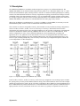
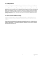


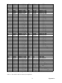
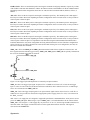
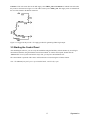
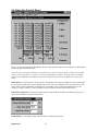
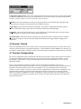

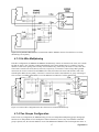
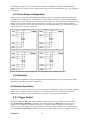
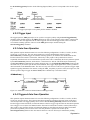
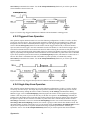
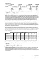
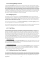
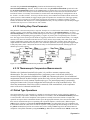
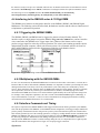
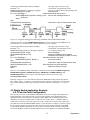
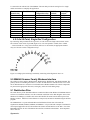
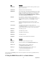
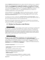
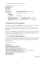
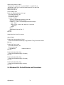
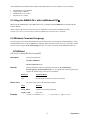
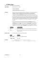
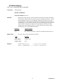
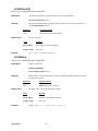
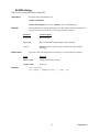
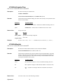
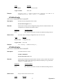
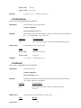
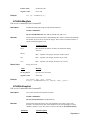
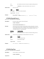
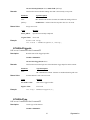
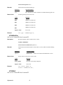
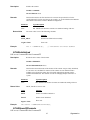
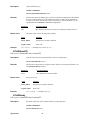
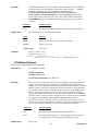
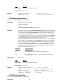
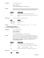
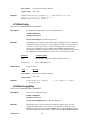
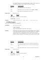
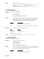
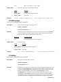
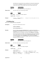
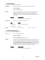
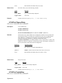
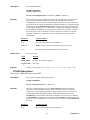


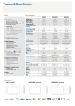
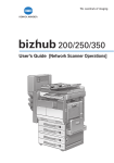

![User's Guide [Advanced Scan Operations]](http://vs1.manualzilla.com/store/data/006865872_1-8b3a85e3ed58d035968500e47824ff56-150x150.png)