1
Allen-Bradley ControlLogix®
Ethernet Driver Help
© 2015 Kepware Technologies
Allen-Bradley ControlLogix Ethernet Driver Help
2
Table of Contents
Table of Contents
2
Allen-Bradley ControlLogix® Ethernet Driver Help
7
Overview
7
Device Setup
9
Cable Diagrams
11
Communications Routing
11
Connection Path Specification
11
Routing Examples
12
Logix Device IDs
15
CompactLogix 5300 Ethernet Device ID
15
Logix Communications Parameters
17
Logix Options
18
Logix Database Settings
20
Logix Database Options
21
Logix Database Filtering
22
1761-NET-ENI Setup
22
Data Highway Plus™ Gateway Setup
23
ControlNet™ Gateway Setup
24
Ethernet/IP Gateway Setup
24
Serial Gateway Setup
25
MicroLogix 1100 Setup
26
ENI DF1/DH+/ControlNet Gateway Communications Parameters
27
28
SLC 500 Slot Configuration
29
SLC 500 Modular I/O Selection Guide
Performance Optimizations
31
Optimizing Communications
31
Optimizing the Application
33
Performance Statistics and Tuning
34
Performance Tuning Example
35
Data Types Description
48
Address Descriptions
49
Logix Addressing
49
MicroLogix Addressing
50
SLC 500 Fixed I/O Addressing
52
SLC 500 Modular I/O Addressing
52
PLC-5 Series Addressing
53
Logix Tag-Based Addressing
54
Address Formats
55
Tag Scope
56
Internal Tags
56
Predefined Term Tags
57
www. kepware.com
Allen-Bradley ControlLogix Ethernet Driver Help
3
Addressing Atomic Data Types
57
Addressing Structure Data Types
58
Addressing STRING Data Type
58
Ordering of Logix Array Data
59
Logix Advanced Addressing
60
Advanced Addressing: BOOL
60
Advanced Addressing: SINT
61
Advanced Addressing: INT
63
Advanced Addressing: DINT
65
Advanced Addressing: LINT
67
Advanced Addressing: REAL
68
70
File Listing
Output Files
71
Input Files
74
Status Files
76
Binary Files
77
Timer Files
77
Counter Files
78
Control Files
78
Integer Files
79
Float Files
80
ASCII Files
80
String Files
81
BCD Files
81
Long Files
82
MicroLogix PID Files
82
PID Files
83
MicroLogix Message Files
84
Message Files
85
Block Transfer Files
86
Function File Listing
86
High-Speed Counter File (HSC)
86
Real-Time Clock File (RTC)
87
Channel 0 Communication Status File (CS0)
88
Channel 1 Communication Status File (CS1)
88
I/O Module Status File (IOS)
89
Automatic Tag Database Generation
90
Tag Hierarchy
90
Controller-to-Server Name Conversions
92
Preparing for Automatic Tag Database Generation
92
Error Codes
94
Encapsulation Error Codes
94
CIP Error Codes
94
www. kepware.com
Allen-Bradley ControlLogix Ethernet Driver Help
4
0x0001 Extended Error Codes
95
0x001F Extended Error Codes
95
95
0x00FF Extended Error Codes
Error Descriptions
97
97
Address Validation Errors
Address <address> is out of range for the specified device or register.
97
Array size is out of range for address <address>.
97
Array support is not available for the specified address: <address>.
97
Data type <type> is not valid for device address <address>.
98
Device address <address> contains a syntax error.
98
Device address <address> is not supported by model <model name>.
98
Device address <address> is read only.
98
Memory could not be allocated for tag with address <address> on device <device name>.
99
Missing address
99
99
Communication Errors
Unable to bind to adapter: <adapter>. Connect failed.
99
Winsock initialization failed (OS error = n).
100
Winsock V1.1 or higher must be installed to use the Allen-Bradley ControlLogix Ethernet device
driver.
100
100
Device-Specific Error Messages
Allen-Bradley ControlLogix Ethernet <Device>: CIP connection size <requested> is not supported
by this device. Automatically falling back to 500 bytes.
100
Device <device name> is not responding.
101
Encapsulation error occurred during a request to device <device name>. [Encap. error=<code>].
101
error occurred during a request to device <device name>. [CIP error=<code>, Ext.
error=<code>].
101
Frame received from device <device name> contains errors.
102
Unable to retrieve the identity for device <device>. [CIP error=<error>, Ext. error=<error>]. All
tags will use Symbolic Protocol Mode.
102
Unable to retrieve the identity for device <device>. [Encap. error=<error>]. All tags will use
Symbolic Protocol Mode.
102
Unable to retrieve the identity for device <device>. Frame received contains errors. All tags will use
Symbolic Protocol Mode.
102
ControlLogix-Specific Error Messages
103
103
Read Errors (Non-Blocking)
Read request for tag <tag address> on device <device name> failed due to a framing error. Tag
deactivated.
103
Unable to read <tag address> on device <device name>. Tag deactivated.
104
Unable to read tag <tag address> on device <device name>. [CIP error=<code>, Ext.
error=<code>].
104
Unable to read tag <tag address> on device <device name>. Controller tag data type <type>
unknown. Tag deactivated.
104
Unable to read tag <tag address> on device <device name>. Data type <type> is illegal for this
tag. Tag deactivated.
104
Unable to read tag <tag address> on device <device name>. Data type <type> not supported.
Tag deactivated.
105
Unable to read tag <tag address> on device <device name>. Tag does not support multi-element
arrays. Tag deactivated.
105
105
Read Errors (Blocking)
www. kepware.com
Allen-Bradley ControlLogix Ethernet Driver Help
5
Read request for <count> element(s) starting at <tag address> on device <device name> failed
due to a framing error. Block deactivated.
106
Unable to read <count> element(s) starting at <tag address> on device <device name>. Block
deactivated.
106
Unable to read <count> element(s) starting at <tag address> on device <device name>. [CIP
error=<code>, Ext. error=<code>].
106
Unable to read <count> element(s) starting at <address> on device <device>. Controller tag data
106
type <type> unknown. Block deactivated.
Unable to read <count> element(s) starting at <address> on device <device>. Data type <type>
is illegal for this block.
107
Unable to read <count> element(s) starting at <address> on device <device>. Data type <type>
not supported.
107
Unable to read <count> element(s) starting at <tag address> on device <device name>. Block
does not support multi-element arrays. Block deactivated.
107
107
Write Errors
Unable to write to <tag address> on device <device name>.
108
Unable to write to tag <tag address> on device <device name>. [CIP error=<code>, Ext.
Status=<code>].
108
Unable to write to tag <tag address> on device <device name>. Controller tag data type <type>
unknown.
108
Unable to write to tag <tag address> on device <device name>. Data type <type> is illegal for this
109
tag.
Unable to write to tag <tag address> on device <device name>. Data type <type> not supported.
109
Unable to write to tag <tag address> on device <device name>. Tag does not support multielement arrays.
109
Write request for tag <tag address> on device <device name> failed due to a framing error.
109
110
Project Synchronization Errors
Encapsulation error occurred while uploading project information. [Encap. error=<code>].
110
Error occurred while uploading project information. [CIP error=<code>, Ext. error=<code>].
110
Framing error occurred while uploading project information.
110
Invalid or corrupt controller project detected while synchronizing. Synchronization will be retried
shortly.
111
Low memory resources.
111
Project download detected while synchronizing. Synchronization will be retried shortly.
111
Unable to read <element> element(s) starting at <address> on device <device name>. Native tag
size mismatch.
112
Unable to read tag <tag name> on device <device name>. Native tag size mismatch.
112
Unable to write to tag <tag name> on device <device name>. Native tag size mismatch.
112
ENI/DH+/ControlNet Gateway Specific Error Messages
112
Device <device name> is not responding. Local node responded with error [DF1 STS=<value>].
112
Unable to read <block size> element(s) starting at <address> on device <device name>. [DF1
STS=<value>, EXT STS=<value>]. Tag(s) deactivated.
113
Unable to read <block size> element(s) starting at <address> on device <device name>. Frame
received contains errors.
113
Unable to write to address <address> on device <device name>. [DF1 STS=<value>, EXT
STS=<value>].
113
Unable to write to address <address> on device <device name>. Frame received contains errors.
114
Unable to write to address <address> on device <device name>. Local node responded with error
[DF1 STS=<value>].
114
Unable to write to function file <address> on device <device name>. Local node responded with
error [DF1 STS=<value>].
114
Automatic Tag Database Generation Errors
www. kepware.com
115
Allen-Bradley ControlLogix Ethernet Driver Help
6
Database error: Array tags <orig. tag name><dimensions> exceed 31 characters. Tags renamed to
115
<new tag name><dimensions>.
Database error: Data type <type> for tag <tag name> not found in tag import file. Tag not added.
115
Database error: Data type for Ref. Tag <tag name> unknown. Setting Alias tag <tag name> data
type to Default (<type>).
115
Database error: Error occurred processing Alias tag <tag name>. Tag not added.
116
Database error: Member data type <type> for UDT <UDT name> not found in tag import file.
Setting to Default type <type>.
116
Database error: Program group <orig. program name> exceeds 31 characters. Program group
renamed to <new program name>.
116
Database error: Tag <orig. tag name> exceeds 31 characters. Tag renamed to <new tag name>.
116
Database error: Unable to resolve CIP data type <hex value> for tag <tag name>. Setting to default
type <logix data type>.
117
Invalid or corrupt controller project detected while synchronizing. Try again later.
117
Project download detected while synchronizing. Try again later.
117
Unable to generate a tag database for device <device name>. Reason: Import file not found.
117
Unable to generate a tag database for device <device name>. Reason: L5K file is invalid or corrupt.
118
Unable to generate a tag database for device <device name>. Reason: Low memory resources.
118
Reference Material
119
Choosing a Protocol Mode
120
Detecting a Change in the Controller Project
121
SoftLogix 5800 Connection Notes
122
Glossary
124
Index
126
www. kepware.com
Allen-Bradley ControlLogix Ethernet Driver Help
7
Allen-Bradley ControlLogix® Ethernet Driver Help
Help version 1.108
CONTENTS
Overview
What is the Allen-Bradley ControlLogix Ethernet Driver?
Device Setup
How do I configure a device for use with this driver?
Communications Routing
How do I communicate with a remote ControlLogix 5000 processor or 1756-DHRIO/1756-CNB Interface Module?
Performance Optimizations
How do I get the best performance from the Allen-Bradley ControlLogix Ethernet Driver?
Data Types Description
What data types does this driver support?
Address Descriptions
How do I address a tag on a Allen-Bradley ControlLogix Ethernet device?
Automatic Tag Database Generation
How can I easily configure tags for the Allen-Bradley ControlLogix Ethernet Driver?
Error Descriptions
What error messages does the Allen-Bradley ControlLogix Ethernet Driver produce?
Error Codes
What are the Allen-Bradley ControlLogix Ethernet error codes?
Reference Material
Where can I find additional information relating to the Allen-Bradley ControlLogix Ethernet Driver?
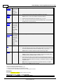
Overview
The Allen-Bradley ControlLogix® Ethernet Driver provides an easy and reliable way to connect Allen-Bradley
ControlLogix Ethernet controllers to OPC client applications, including HMI, SCADA, Historian, MES, ERP, and
countless custom applications.
Supported Allen-Bradley Controllers
ControlLogix® 5500 Series
Communications with ControlLogix can be accomplished through an Ethernet/IP communication module for
Ethernet communications or through a 1761-NET-ENI module for Ethernet-to-serial communications using the
controller's serial port.
CompactLogix™ 5300 Series
Ethernet communications with CompactLogix requires a processor with a built-in Ethernet/IP port such as the
1769-L35E. Communications with CompactLogix otherwise requires a 1761-NET-ENI module for Ethernet-toserial communications using the controller's serial port.
FlexLogix 5400 Series
Communications with FlexLogix can be accomplished through a 1788-ENBT daughter card for Ethernet
communications or through a 1761-NET-ENI module for Ethernet-to-serial communications using the controller's
serial port.
SoftLogix 5800
The driver supports the Allen-Bradley SoftLogix 5800 Series Controller and requires an Ethernet card in the
SoftLogix PC.
Data Highway Plus™ Gateway
www. kepware.com
Allen-Bradley ControlLogix Ethernet Driver Help
The driver supports the PLC-5 Series and SLC 500 Series with a Data Highway Plus interface. This is
accomplished through a DH+ gateway and requires one of the aforementioned PLCs, an Ethernet/IP
communication module, and a 1756-DHRIO-interface module (both residing in the ControlLogix rack).
ControlNet™ Gateway
The driver supports the PLC-5C Series. This is accomplished through a ControlNet gateway and requires the
aforementioned PLC, an Ethernet/IP communication module, and a 1756-CNB/CNBR interface module (both
residing in the ControlLogix rack).
1761-NET-ENI
The driver supports communications with the 1761-NET-ENI device. The ENI device adds extra flexibility in
device networking and communications by providing an Ethernet-to-serial interface for both Full Duplex DF1
controllers and Logix controllers. In conjunction with the ENI device, this driver supports the following:
l
ControlLogix 5500 Series*
l
CompactLogix 5300 Series*
l
FlexLogix 5400 Series*
l
MicroLogix Series
l
SLC 500 Fixed I/O Processor
l
SLC 500 Modular I/O Series
l
PLC-5 Series
*These models require 1761-NET-ENI Series B or higher.
MicroLogix™ 1100
The driver supports communications with the MicroLogix 1100 (CH1 Ethernet) using Ethernet/IP.
All trademarks are the property of their respective owners.
www. kepware.com
8
Allen-Bradley ControlLogix Ethernet Driver Help
9
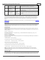
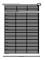
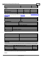
Device Setup
Supported Devices
Device
Communications
ControlLogix 5550 / 5553 / 5555 / 5561 /
5562 / 5563 / 5564 / 5565 / 5571 / 5572 /
5573 / 5574 / 5575 processors
Via 1756-ENBT / ENET / EN2F / EN2T / EN2TR / EN3TR /
EWEB / EN2TXT Ethernet module
Via Serial Gateway
Via 1761-NET-ENI Series B or higher using Channel 0 (serial)
CompactLogix 5320 / 5323 / 5330 / 5331 /
5332 / 5335 / 5343 / 5345 / 5370
Built-in Ethernet/IP port on processors with E suffix*
Via Serial Gateway
Via 1761-NET-ENI Series B or higher using Channel 0 (serial)
FlexLogix 5433 / 5434 processors
Via 1788-ENBT Ethernet daughter card
Via Serial Gateway
Via 1761-NET-ENI Series B or higher using Channel 0 (serial)
SoftLogix 5810 / 5830 / 5860 processors
Via SoftLogix Ethernet / IP Messaging module
Via Serial Gateway
MicroLogix 1000 / 1200 / 1500
Via 1761-NET-ENI
Via Ethernet/IP Gateway
MicroLogix 1100 / 1400
Via MicroLogix 1100 / 1400 Channel 1 (Ethernet)
Via 1761-NET-ENI
Via Ethernet/IP Gateway
SLC 500 Fixed I/O Processor
Via 1761-NET-ENI
Via Ethernet/IP Gateway
SLC 500 Modular I/O Processors (SLC 5/01,
SLC 5/02, SLC 5/03, SLC 5/04, SLC 5/05)
Via DH+ Gateway**
Via 1761-NET-ENI
Via Ethernet/IP Gateway
PLC-5 series (excluding the PLC5/250 series) Via DH+ Gateway
Via 1761-NET-ENI
Via Ethernet/IP Gateway
PLC-5/20C, PLC-5/40C, PLC-5/80C
Via ControlNet Gateway
Via 1761-NET-ENI
Via Ethernet/IP Gateway
*For example, 1769-L35E.
**This driver supports any SLC 500 series PLC that supports DH+ or that can be interfaced to a DH+ network
(such as the KF2 interface module).
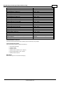
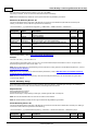
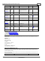
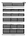
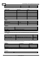
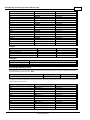
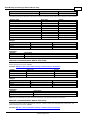
Firmware Versions
Device
Version
ControlLogix 5550 (1756-L1)
11.35 - 13.34
ControlLogix 5553 (1756-L53)
11.28
ControlLogix 5555 (1756-L55)
11.32 - 16.04
ControlLogix 5561 (1756-L61)
12.31 - 20.11
ControlLogix 5562 (1756-L62)
12.31 - 20.11
www. kepware.com
Allen-Bradley ControlLogix Ethernet Driver Help
10
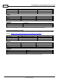
ControlLogix 5563 (1756-L63)
11.26 - 20.11
ControlLogix 5564 (1756-L64)
16.03 - 20.11
ControlLogix 5565 (1756-L65)
16.03 - 20.11
ControlLogix 5571 (1756-L71)
20.11 - 24.11
ControlLogix 5572 (1756-L72)
19.11 - 24.11
ControlLogix 5573 (1756-L73)
18.12 - 23.12
ControlLogix 5574 (1756-L74)
19.11 - 24.11
ControlLogix 5575 (1756-L75)
18.12 - 24.11
CompactLogix 5370 (1769-L1ER)
20.11 - 24.11
CompactLogix 5320 (1769-L20)
11.27 - 13.18
CompactLogix 5323 (1769-L23)
17.05 - 20.11
CompactLogix 5370 (1769-L2ER)
20.11 - 24.11
CompactLogix 5330 (1769-L30)
11.27 - 13.18
CompactLogix 5331 (1769-L31)
16.22 - 20.11
CompactLogix 5332 (1769-L32)
16.22 - 20.11
CompactLogix 5335 (1769-L35)
16.22 - 20.11
CompactLogix 5370 (1769-L3ER)
20.11 - 24.11
CompactLogix 5343 (1768-L43)
15.07 - 20.11
CompactLogix 5345 (1768-L45)
16.24 - 20.11
FlexLogix 5433 (1794-L33)
11.25 - 13.33
FlexLogix 5434 (1794-L34)
11.25 - 16.02
SoftLogix 5800 (1789-L60)
16.00 - 20.01
ControlLogix, CompactLogix, and FlexLogix Serial
Communications
1761-NET-ENI Series B or higher or Serial
Gateway
MicroLogix 1100 (1763-L16AWA/BWA/BBB)
1.1
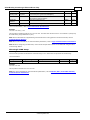
Communication Protocol
The Communications Protocol is Ethernet/IP (CIP over Ethernet) using TCP/IP.
Logix and Gateway Models
Logix and Gateway models support the following:
l
Connected Messaging
l
Symbolic Reads
l
Symbolic Writes
l
Symbol Instance Reads (V21 or higher)
l
Physical (DMA) Reads (V20 or lower)
l
Symbol Instance Writes
ENI Models
ENI models support unconnected messaging.
www. kepware.com
Allen-Bradley ControlLogix Ethernet Driver Help
11
Cable Diagrams
Communications Routing
Routing provides a way to communicate with a remote device over various networks. It can be thought of as a
bridge between the local device and a remote device even if they are on two different field bus networks. Access
to a remote (destination) backplane allows for direct communication with the supported modules located on this
backplane. Supported modules include the following:
l
ControlLogix 5500 processor for ControlLogix applications.
l
SoftLogix 5800 processor for SoftLogix applications.
l
1756-DHRIO interface module for DH+ Gateway applications.
l
1756-CNB or 1756-CNBR interface module for ControlNet Gateway applications.
A routing path is a series of backplane hops, whose last hop points to the destination backplane. Each hop
requires a Logix backplane (not a Logix processor). An individual hop can utilize one of the following networks as
its medium:
l
ControlNet
l
DH+
l
TCP/IP (Ethernet/IP)
Important: Routing is not supported for ENI and MicroLogix 1100 models.
Connection Path Specification
The routing path is specified in the device ID. As with non-routing applications, communication originates from
the Allen-Bradley ControlLogix Ethernet Driver on the PC and is directed at the local Ethernet module. Once at this
local Ethernet module, the device ID specifies a way out of the module and onto the backplane, just like with nonrouting applications. The routing path directs the message to the desired Logix backplane. The device ID also
determines what device is communicated with (such as the ControlLogix processor, SoftLogix processor, DH+
node, or ControlNet node).
The routing path specification begins and ends with the left and right bracket respectively ([ ]). The path itself is
a series of port/link address pairs, identical to the communication path syntax in RSLogix 5000 Message
Configuration dialog.
www. kepware.com
Allen-Bradley ControlLogix Ethernet Driver Help
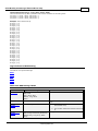
12
Designator
Type
Description
Formats
Range
Port ID
Specifies a way out of the interface module in question.*
Decimal
065535
Decimal
0-255
Link Address If the corresponding port is the backplane, the link address is the slot
number of the interface module that goes out.
If the corresponding port is an interface module port, the link address
specifies a destination node as follows.
- DH+/ControlNet: node ID
- Ethernet/IP communication module: IP address
- SoftLogix Ethernet/IP module: IP address
*For more information, refer to "Port Reference" below.
Single Hop
IP Address, Port ID0, [Link Address0, Port ID1, Link Address1, Port ID2], Link Address2.
Multi-Hop (N Hops)
IP Address, Port ID0, [Link Address0, Port ID1, Link Address1, Port ID2, Link Address2, ... Port ID(N+1), Link
Address(N+1), Port ID(N+2)], Link Address(N+2).
Note 1: The last port ID in the path (Port ID2 and Port ID(N+2) for single-hop and multi-hop respectively) must
be 1 (port for backplane).
Note 2: Port ID0 must be 1 (port for backplane). Link Address2 and Link Address (N+2) are the slot numbers of
the remote Logix processor/1756-DHRIO module/1756-CNB module.
Port Reference
Interface Module
Port 1
Port 2
Port 3
Ethernet/IP Communication Module
Backplane
Ethernet Network
N/A
SoftLogix Ethernet/IP Messaging Module
Virtual Backplane Ethernet Network
N/A
1756-DHRIO
Backplane
DH+ Network on Ch. A
DH+ Network on Ch. B
1756-CNB
Backplane
ControlNet Network
N/A
Application Notes
1. Messages cannot be routed in or out of the same interface module channel more than once within the
path. Doing so results in CIP error 0x01 Ext. error 0x100B.
2. For multiple channel interface modules, messages cannot be routed into and then immediately out of that
same module (using different channels), regardless of whether the message is directed to the backplane
first or avoids the backplane all together. As previously mentioned, the latter is not supported since each
hop requires a ControlLogix backplane. An example would be to route a DH+ message from one DH+ link
(such as Channel A of 1756-DHRIO) to another DH+ link (such as Channel B of same 1756-DHRIO)
through one 1756-DHRIO-interface module. This is commonly referred to as Remote DH+ messaging and
is not supported.
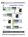
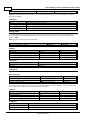
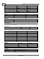
Routing Examples
The routing examples below include the entire device ID minus the IP of the local 1756-ENBT. The perspective of
the device ID/routing path is from the local 1756-ENBT Module. Hop descriptions are in the following form:
Link Address (N), Port ID(N+1), Link Address(N+1), Port ID(N+2)
Note: For more information, refer to Connection Path Specification. For further details on building a
connection/routing path, refer to Allen-Bradley Publication 1756-6.5.14, pp. 4-5 through 4-8.
In the illustration below, all DH+/ControlNet node IDs are specified in Decimal format. The node ID specified in
the PLC and displayed in RSWho is in Octal format. Descriptions of the colors are as follows:
l
Green = Ethernet
l
Blue = DH+
www. kepware.com
Allen-Bradley ControlLogix Ethernet Driver Help
13
l
Orange = ControlNet
Note: For more information, refer to Data Highway Plus™ Gateway Setup and ControlNet™ Gateway
Setup.
Example 1
Logix5550 to PLC-5 via DH+ Gateway.
Destination Node
Model
Routing
Device ID less IP
PLC-5/20 (D)
DH+ Gateway
No
1,1.B.9
Example 2
Logix5550 to PLC-5C via CN Gateway.
www. kepware.com
Allen-Bradley ControlLogix Ethernet Driver Help
14
Destination Node
Model
Routing
Device ID less IP
PLC-5/40C (B)
CN Gateway
No
1,2.A.1
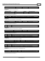
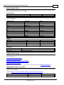
Example 3
Logix5550 to Logix5550 via routing over DH+.
Destination Node
Model
Routing
Device ID less IP
Logix5550 (C)
ControlLogix 5550
Yes
1,[1,2,8,1],0
Routing Path Breakdown for Example 3.
Hop
Segment
Description
1
1,2,8,1
Slot 1 (DHRIO) -> Port 2 (DH+ Ch A) -> DH+ Node 8 -> Logix C backplane
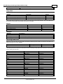
Example 4
Logix5550 to PLC-5C via CN Gateway, routing over DH+.
Destination Node
Model
Routing
Device ID less IP
PLC-5/80C (E)
CN Gateway
Yes
1,[1,2,8,1],2.A.3
Routing Path Breakdown for Example 4.
Hop
Segment
Description
1
1,2,8,1
Slot 1 (DHRIO) -> Port 2 (DH+ Ch A) -> DH+ Node 8 -> Logix C backplane
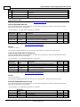
Example 5
Logix5550 to Logix5550 via routing over DH+, ControlNet
Destination Node
Model
Routing
Device ID less IP
Logix5550 (F)
ControlLogix 5550
Yes
1,[1,2,8,1,2,2,15,1],0
Routing Path Breakdown for Example 5.
Hop
Segment
Description
1
1,2,8,1
Slot 1 (DHRIO) -> Port 2 (DH+ Ch A) -> DH+ Node 8 -> Logix C backplane
2
2,2,15,1
Slot 2 (CNB) -> Port 2 (CN Ch A) -> CN Node 15 -> Logix F backplane
Example 6
Logix5550 to SLC 5/04 via routing over DH+, ControlNet.
Destination Node
Model
Routing
Device ID less IP
SLC 5/04 (G)
DH+ Gateway
Yes
1,[1,2,8,1,2,2,15,1],1.A.2
Routing Path Breakdown for Example 6.
Hop
Segment
Description
1
1,2,8,1
Slot 1 (DHRIO) -> Port 2 (DH+ Ch A) -> DH+ Node 8 -> Logix C backplane
2
2,2,15,1
Slot 2 (CNB) -> Port 2 (CN Ch A) -> CN Node 15 -> Logix F backplane
Example 7
Logix5550 to Logix5550 via routing over DH+, ControlNet, Ethernet.
Destination Node Model
Routing
Device ID less IP
Logix5550 (H)
Yes
1,[1,2,8,1,2,2,15,1,3,2,192.192.180.101,1],0
ControlLogix 5550
Routing Path Breakdown for Example 7.
www. kepware.com
Allen-Bradley ControlLogix Ethernet Driver Help
15
Hop
Segment
Description
1
1,2,8,1
Slot 1 (DHRIO) -> Port 2 (DH+ Ch A) -> DH+ Node 8 -> Logix C
backplane
2
2,2,15,1
Slot 2 (CNB) -> Port 2 (CN Ch A) -> CN Node 15 -> Logix F backplane
3
3,2,192.192.180.101,1
Slot 3 (ENBT) -> Port 2 -> Remote1756-ENBT IP -> Logix H backplane
Logix Device IDs
For information on ENI device ID setup, refer to 1761-NET-ENI Setup.
ControlLogix 5500 Ethernet
The device ID specifies the device IP address, as well as the slot number in which the controller CPU resides.
Device IDs are specified as the following:
<IP or hostname>,1,[<optional routing path>],<CPU Slot>
Designator
Designator
Type*
Description
Formats Range
IP/Host Name N/A
IP Address or host name.
Decimal
0-255
1
Port ID
Port to backplane.
Decimal
1
Optional
Routing Path
Multiple Link,
port pairs
Specifies a way out of the Ethernet/IP interface module
and must equal 1 (port to the backplane).
Decimal
*
CPU Slot
Link Address
Slot number of the ControlLogix processor.
Decimal
0-255
*For more information, refer to Connection Path Specification.
Example
123.123.123.123,1,0
This equates to an Ethernet/IP of 123.123.123.123. The port ID is 1 and the CPU resides in slot 0.
CompactLogix 5300 Ethernet Device ID
The device ID specifies the device IP address, as well as the slot number in which the controller CPU resides.
Device IDs are specified as the following:
<IP or hostname>,1,[<optional routing path>],<CPU Slot>
Designator
Designator
Type*
Description
Formats
Range
IP/Host Name
N/A
CompactLogix Ethernet IP Address or host name.
Decimal
0-255
1
Port ID
Port to backplane.
Decimal
1
Optional
Routing Path
Multiple Link,
port pairs
Specifies a way out of the Ethernet port and must
equal 1 (port to the backplane).
Decimal
*
CPU Slot
Link Address
Slot number of the CompactLogix processor.
Decimal
0-255
*For more information, refer to Connection Path Specification.
Example
123.123.123.123,1,0
This equates to CompactLogix IP of 123.123.123.123. The port ID is 1 and the CPU resides in slot 0.
FlexLogix 5400 Ethernet Device ID
The device ID specifies the device IP address, as well as the slot number in which the controller CPU resides.
Device IDs are specified as the following:
<IP or hostname>,1,[<optional routing path>],<CPU Slot>
Designator
Designator
Type*
Description
Formats Range
IP/Host Name N/A
1788-ENBT IP Address or host name.
Decimal
0-255
1
Port ID
Port to backplane.
Decimal
1
Optional
Multiple Link,
Specifies a way out of the 1788-ENBT interface module
Decimal
*
www. kepware.com
Allen-Bradley ControlLogix Ethernet Driver Help
Routing Path
port pairs
and must equal 1 (port to the backplane).
CPU Slot
Link Address
Slot number of the FlexLogix processor.
16
Decimal
0-255
*For more information, refer to Connection Path Specification.
Example
123.123.123.123,1,0
This equates to 1788-ENBT IP of 123.123.123.123. The port ID is 1 and the CPU resides in slot 0.
SoftLogix 5800 Device ID
The device ID specifies the SoftLogix PC IP address, as well as the virtual slot number in which the controller CPU
resides. Device IDs are specified as the following:
<IP or hostname>,1,[<optional routing path>],<CPU Slot>
Designator
Type*
Description
Formats Range
IP/Host
Name
N/A
SoftLogix PC NIC IP Address or host name.
Decimal
0-255
1
Port ID
Port to backplane.
Decimal
1
Optional
Routing Path
Multiple Link,
port pairs
Specifies a way out of the Ethernet/IP Messaging module
and must equal 1 (port to the virtual backplane).
Decimal
*
CPU Slot
Link Address
Slot number of the SoftLogix processor in the virtual
backplane.
Decimal
0-255
Designator
*For more information, refer to Connection Path Specification.
Example
123.123.123.123,1,1
This equates to SoftLogix PC IP Address of 123.123.123.123. The port ID is 1 and the CPU resides in slot 1.
Note: For information on supplementing a device ID with a routing path to a remote backplane, refer to
Communications Routing.
See Also: SoftLogix 5800 Connection Notes
www. kepware.com
Allen-Bradley ControlLogix Ethernet Driver Help
17
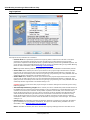
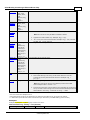
Logix Communications Parameters
Descriptions of the parameters are as follows:
l
l
TCP/IP Port: This parameter specifies the TCP/IP port number that the device is configured to use. The
default setting is 44818.
Connection Size: This parameter specifies the number of bytes available on the CIP connection for data
requests and responses. The valid range is 500 to 4000 bytes. The default setting is 500 bytes.
Note: Only the ControlLogix 5500 and CompactLogix 5300 device models support this feature. To support
connection sizes greater than 500 bytes, the device must support Firmware version 20 or later controllers
and Ethernet bridge EN3x, EN2x, or EN5.x. Older Ethernet modules like ENBT and ENET do not support
this feature. Devices that do not meet the necessary requirements automatically fall back to the default
setting of 500 bytes, although the requested size is re-attempted after communications failure.
Important: The Connection Size value may also be requested through the System tag "_
CIPConnectionSizeRequested." For more information, refer to Internal Tags.
l
Inactivity Watchdog: This parameter specifies the amount of time a connection can remain idle
(without read/write transactions) before being closed by the controller. In general, the larger the
watchdog value, the more time it takes for connection resources to be released by the controller and vice
versa. The default setting is 32 seconds.
Note: If the Event Log error "CIP connection timed-out while uploading project information" occurs
frequently, increase the Inactivity Watchdog value. Otherwise, an Inactivity Watchdog value of 32
seconds is preferred.
l
Array Block Size: This parameter specifies the maximum number of array elements to read in a single
transaction. The value is adjustable and ranges from 30 to 3840 elements. The default setting is 120
elements.
Note: For Boolean arrays, a single element is considered a 32-element bit array. Thus, setting the block
size to 30 elements translates to 960 bit elements, whereas 3840 elements translate to 122880 bit
elements.
www. kepware.com
Allen-Bradley ControlLogix Ethernet Driver Help
18
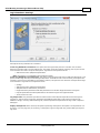
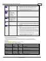
Logix Options
Descriptions of the parameters are as follows:
l
Protocol Mode: This parameter specifies how Logix tag data is read from the controller. This option
should only be changed by advanced users who are looking to increase client/server tag update
performance. Options include Symbolic Mode, Logical Non-Blocking Mode and Logical Blocking Mode. The
server project is interchangeable between these three modes. The default setting is Logical Non-Blocking
Mode. For more information, refer to Choosing a Protocol Mode.
Note: Logical Non-Blocking Mode and Logical Blocking Mode are not available to Serial Gateway models.
l
l
Online Edits: When enabled, the driver synchronizes its own project image with that of the controller
project when an online project edit (or project download from RSLogix/Studio5000) is detected. This
option prevents unnecessary errors from occurring during a project change. It is only available when the
selected protocol is Logical Mode. The default setting is Yes.
Offline Edits: When enabled, the driver synchronizes its own project image with that of the controller
project when an offline project edit (or project download from RSLogix/Studio5000) is detected. This
option prevents unnecessary errors from occurring during a project change. It is only available when the
selected protocol is Logical Mode. The default setting is Yes.
Caution: Failure to synchronize with project changes can lead to reading from and writing to the wrong
Native tag address.
l
l
Automatically Read String Length: When checked, the driver automatically reads the LEN member of
the STRING structure whenever the DATA member is read. The DATA string is terminated at the first null
character encountered, the character whose position equals the value of LEN, or the maximum string
length of DATA (whichever occurs first). When unchecked, the driver bypasses the LEN member read
and terminates the DATA string at either the first null character encountered or the maximum string
length of DATA (whichever occurs first). Therefore, if LEN is reduced by an external source without
modification to DATA, the driver does not terminate DATA according to this reduced length. The default
setting is Yes.
Default Type: This parameter specifies the data type assigned to a client/server tag when the default
type is selected during tag addition, modification, or import. The default setting is Default. For more
information, refer to Default Data Type Conditions.
Note 1: If Default is selected, the driver retrieves the Logix tag's data type from the controller when a
www. kepware.com
Allen-Bradley ControlLogix Ethernet Driver Help
19
client is accessing a tag dynamically and does not explicitly assign a data type to the item. For example, a
tag exists in the controller that is called "MyTag" with a data type of REAL. The corresponding client item
is specified as "Channel1.Device1.MyTag" with no data type assigned. With Default specified as the
default data type in the server, the driver reads "MyTag" from the controller and determine that it is a
REAL in the response. Thus, it provides the client item a data type of Float.
Note 2: Since the majority of I/O module tags are not bit-within-Word/DWord tags, it is advised that the
default type be set to the majority data type as observed in the .ACD project. For example, if 75% of alias
I/O module tags are INT tags, set the default type to INT.
l
Enable Performance Statistics: The Allen-Bradley ControlLogix Ethernet Driver has the ability to
gather communication statistics to help determine the driver's performance. When checked, this option is
enabled. The driver tracks the number and types of client/server tag updates. On restart of the server
application, the results are displayed in the server's Event Log. The default setting is No.
Note: Once a project configuration is designed for optimal performance, it is recommended that users
disable Performance Statistics. Furthermore, since the statistics are outputted to the Event Log on
shutdown, the server must be re-launched to view the results.
See Also: Detecting a Change in the Controller Project
Default Data Type Conditions
Client/server tags are assigned the default data type when any of the following conditions occur:
1. A Dynamic tag is created in the client with Native as its assigned data type.
2. A Static tag is created in the server with Default as its assigned data type.
3. In offline automatic tag generation, when an unknown data type is encountered in the L5K/L5X file for
UDT members and Alias tags.
4. In offline automatic tag generation, when an alias of the following type is encountered in the L5K/L5X:
a. Alias of an alias.
b. Alias of non bit-within-Word/DWord I/O module tag. For example, if tag "AliasTag" references
I/O module tag "Local:5:C.ProgToFaultEn" @ BOOL, the data type for "AliasTag" cannot be
resolved, so this default type is assigned to it. On the other hand, if "AliasTag" references I/O
module tag "Local:5:C.Ch0Config.RangeType.0" @ BOOL, the data type can be resolved because
of the . (dot) BIT that defines it as a bit-within-Word/DWord. Aliases of bit-within-Word/DWord
I/O module tags are automatically assigned the Boolean data type.
www. kepware.com
Allen-Bradley ControlLogix Ethernet Driver Help
20
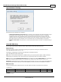
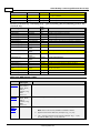
Logix Database Settings
Descriptions of the parameters are as follows:
Create Tag Database from Device: This option retrieves tags directly from the controller over the same
Ethernet connection that is used for data access. This option is fast and imports most tags, but requires access
to the controller and does not import descriptions. Tags that are not imported include:
l
Add-On Instruction (AOI) InOut parameters
Note: This feature is not available to Serial Gateway models.
Create Tag Database from Import File: This option retrieves tags directly from an RSLogix L5K/L5X file. This
option retrieves tags directly from an RSLogix L5K/L5X file. Controller access is not necessary, descriptions are
imported, and users have the ability to work offline. However, this option is slow and does not import all the tags
in the controller. Tags that are not imported include:
l
I/O tags
l
Add-On Instruction (AOI) InOut parameters
l
AOI parameters that alias other parameters
l
Equipment Phase parameters that alias parameters from another Equipment Phase or Program
l
Program parameters that alias parameters from another Program or Equipment Phase
l
Timer/Counter CTL bits
Tag Import File: This parameter specifies the exact location of the L5K/L5X import file from which tags are
imported.d. This file will be used when Automatic Tag Database Generation is instructed to create the tag
database. All tags, including Global and Program, will be imported and expanded according to their respective
data types.
Display Descriptions: When checked, this option imports tag descriptions. Descriptions are imported for nonstructure, non-array tags only. If necessary, a description is given to tags with long names stating the original
tag name.
www. kepware.com
Allen-Bradley ControlLogix Ethernet Driver Help
21
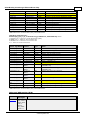
Logix Database Options
Descriptions of the parameters are as follows:
l
Limit Tag/Group Names to 31 Characters?: When checked, this parameter limits the tag and group
names to 31 characters. Before OPC server version 4.70, tag and group name lengths were restricted to
31 characters; however, the current length restriction of 256 characters can fit Logix 40 character Logix
Tag names. The default setting is unchecked.
Note: If an older OPC server version was used to import tags via L5K/L5X import, inspect the Event Log or
scan the server project to see if any tags were cut due to the character limit. If so, it is recommended that
this option be enabled to preserve the server tag names. OPC client tag references are not affected. If not
chosen, new longer tag names are created for those that were clipped. OPC clients referencing the
clipped tag would have to be changed to reference the new tag.
If an older OPC server version was used to import tags via L5K/L5X import and no tags were clipped due
to the 31 character limit, do not select this option. Similarly, if tags were imported via L5K/L5X with OPC
server version 4.70 or above, do not select this option.
l
Tag Hierarchy: This parameter specifies the tag hierarchy. Options include Condensed and Expanded.
The default setting is Expanded. Descriptions of the options are as follows:
l
l
Condensed Mode: In this mode, the server tags created by automatic tag generation follow a
group/tag hierarchy consistent with the tag's address. Groups are created for every segment
preceding the period.
Expanded Mode: In this mode, the server tags created by automatic tag generation follow a
group/tag hierarchy consistent with the tag hierarchy in RSLogix 5000. This is the default
setting. Groups are created for every segment preceding the period as in Condensed mode, but
groups are also created to represent logical groupings.
Note: For more information on the groups created, refer to Tag Hierarchy.
Note: To enable this functionality, check Allow Automatically Generated Subgroups in device
properties.
See Also: Controller-to-Server Name Conversions
www. kepware.com
Allen-Bradley ControlLogix Ethernet Driver Help
22
Logix Database Filtering
Descriptions of the parameters are as follows:
l
l
Impose Array Element Count Limit: When checked, an array element count limit is imposed. Tags in
the controller can be declared with very large array dimensions. By default, arrays are completely
expanded during the tag generation process, which becomes time consuming for large arrays. By
imposing a limit, only a specified number of elements from each dimension are generated. Limits only
takes effect when the array dimension size is exceeds the limit. The default setting is unchecked.
Element Count Limit: This parameter is used to specify the element count limit. The default setting is
2000.
1761-NET-ENI Setup
1761-NET-ENI provides a means of communicating with ControlLogix, CompactLogix, FlexLogix, MicroLogix, SLC
500, and PLC-5 Series PLCs on Ethernet with the Allen-Bradley ControlLogix Ethernet Driver.
Requirements
MicroLogix, SLC 500, or PLC-5 series PLC supporting Full Duplex DF1 utilizing the CH0 RS232 channel.
1761-NET-ENI Device Series A, B, C, or D.
ControlLogix, CompactLogix or FlexLogix PLC utilizing the CH0 RS232 channel.
1761-NET-ENI Device Series B and newer.
Note 1: For communications parameters, database settings, and project/protocol options, ENI ControlLogix,
CompactLogix, and FlexLogix users should refer to the "Logix Setup" book in the Table of Contents.
Note 2: To turn on the CompactLogix Routing option (located in the utility's ENI IP Addr tab), use the ENI /
ENIW utility supplied by Allen-Bradley. This was tested on an ENI module with Firmware revision 2.31.
Important: The ENI module has a limited number of TCP connections. As such, users should avoid applications
that communicate with the module (such as RSLinx/RSWho) so that connections are available for the driver.
ENI Device ID
The device ID specifies the IP address of the 1761-NET-ENI. Device IDs are specified as the following:
<IP Address>
Designator
Designator Type
Description
Formats
Range
IP Address
N/A
1761-NET-ENI IP address
Decimal
0-255
Example
123.123.123.123
www. kepware.com
Allen-Bradley ControlLogix Ethernet Driver Help
23
This equates to an ENI IP of 123.123.123.123. Since the device only supports Full Duplex DF1, a node ID is not
required.
Note: For more information on communications parameters, refer to Logix Communications Parameters.
Data Highway Plus™ Gateway Setup
DH+ Gateway provides a means of communicating with SLC 500 and PLC-5 series PLC on DH+ with the AllenBradley ControlLogix Ethernet Driver.
Requirements
Ethernet/IP Interface module.
1756-DHRIO Interface Module with appropriate channel configured for DH+.
SLC500 or PLC-5 series PLC on DH+ network.
Note: DH+ Gateway models do not support automatic tag database generation.
DH+ Gateway Device ID
The device ID specifies the device IP address as well as the DH+ parameters necessary for making a connection.
Device IDs are specified as the following:
<IP or hostname>,1,[<optional routing path>],<DHRIO Slot>.<DHRIO Channel>.<DH+ Node ID (dec)>
Designator
Designator
Type*
Description
Formats Range
IP/Host Name N/A
IP Address or host name.
Decimal
0-255
1
Port ID
Port to backplane.
Decimal
1
Optional
Routing Path
Multiple Link,
port pairs
Specifies a way out of the Ethernet/IP interface module
and must equal 1 (port to the backplane).
Decimal
*
DHRIO Slot
Link Address
Slot number of the 1756-DHRIO interface module.
Decimal
0-255
DHRIO
Channel
DH+ channel to use.
Alpha
A and
B
DH+ Node ID
DH+ node ID of target PLC in Decimal Format.**
Decimal
0-99
*For more information, refer to Connection Path Specification.
**For more information, refer to "Node ID Octal Addressing" below.
Example
123.123.123.123,1,2.A.3
This equates to an Ethernet/IP of 123.123.123.123. The DH+ card resides in slot 2: use DH+ channel A and
addressing target DH+ Node ID 3 (dec).
Node ID Octal Addressing
The DH+ node ID is specified in Octal format in the PLC and requires a conversion to Decimal format for use in the
DH+ Gateway device ID. The node ID can be located in RSWho within RSLinx. It is displayed in Octal format.
Example
DH+ Node 10 (octal) in RSWho = DH+ Node 8 (decimal) in DH+ Gateway device ID.
It is important to verify communications with the proper controller. In the example above, if 10 was entered as
the DH+ node ID in the DH+ Gateway device ID, then communications would take place with Node 12 (octal
equivalent of 10 decimal) and not Node 10 (octal). If Node 12 (octal) does not exist, then the DHRIO module
would return DF1 STS 0x02. This means that the link layer cannot guarantee delivery of the packet. In short, the
DH+ node cannot be located on the DH+ network.
Note 1: For information on supplementing a device ID with a routing path to a remote DH+ node, refer to
Communications Routing.
Note 2: For more information on communications parameters, refer to ENI DF1/DH+/ControlNet Gateway
Communications Parameters.
www. kepware.com
Allen-Bradley ControlLogix Ethernet Driver Help
24
ControlNet™ Gateway Setup
ControlNet Gateway provides a means of communicating with PLC-5C series PLCs on ControlNet with the AllenBradley ControlLogix® Ethernet Driver.
Requirements
Ethernet/IP Interface Module.
1756-CNB or 1756-CNBR Interface Module.
PLC-5C series PLC on ControlNet network.
Note: ControlNet Gateway models do not support automatic tag database generation.
ControlNet Gateway Device ID
The device ID specifies the device IP address in addition to the ControlNet parameters necessary for making a
connection. Device IDs are specified as the following:
<IP or hostname>,1,[<optional routing path>],<CNB Slot>.<CNB Channel>.<ControlNet Node ID (dec)>
Designator
Type*
Description
Formats Range
IP/Host
Name
N/A
IP Address or host name.
Decimal
0-255
1
Port ID
Port to backplane.
Decimal
1
Optional
Routing Path
Multiple Link,
port pairs
Specifies a way out of the Ethernet/IP communication
module and must equal 1 (port to the backplane).
Decimal
*
CNB Slot
Link Address
Slot Number of the 1756-CNB/CNBR interface module.
Decimal
0-255
CNB Channel
Port ID
The ControlNet channel to use.
Alpha
A and
B
ControlNet
Node ID
Link Address
ControlNet node ID of target PLC in decimal format.**
Decimal
0-99
Designator
*For more information, refer to Connection Path Specification.
**For more information, refer to "Node ID Octal Addressing" below.
Example
123.123.123.123,1,2.A.3
This equates to an Ethernet/IP of 123.123.123.123. The ControlNet card resides in slot 2: use ControlNet
channel A and addressing target ControlNet Node ID 3.
Node ID Octal Addressing
The ControlNet node ID is specified in Octal format in the PLC and requires a conversion to Decimal format for use
in the ControlNet Gateway device ID. The node ID can be located in RSWho within RSLinx. It is displayed in Octal
format.
Example
CN node 10 (octal) in RSWho = CN node 8 (decimal) in ControlNet Gateway device ID.
It is important to verify communications with the proper controller. In the example above, if 10 was entered as
the ControlNet node ID in the ControlNet Gateway device ID, communications takes place with Node 12 (octal
equivalent of 10 decimal), not Node 10 (octal). If Node 12 (octal) does not exist, the CNB module returns DF1 STS
0x02. This means that the link layer could not guarantee delivery of the packet. In short, the ControlNet node
could not be located on the ControlNet network.
Note 1: For more information on supplementing a device ID with a routing path to remote ControlNet node, refer
to Communications Routing.
Note 2: For more information on communications parameters, refer to ENI DF1/DH+/ControlNet Gateway
Communications Parameters.
Ethernet/IP Gateway Setup
Ethernet/IP Gateway provides a means of communicating with MicroLogix, SLC 500, and PLC-5 series PLC on
Ethernet/IP with the Allen-Bradley ControlLogix Ethernet Driver.
Requirements
www. kepware.com
Allen-Bradley ControlLogix Ethernet Driver Help
25
2 or more Ethernet/IP Interface modules (such as 1756-ENBT).
MicroLogix, SLC500, or PLC-5 series PLC with Ethernet/IP connectivity.
Note: EthernetIP Gateway models do not support automatic tag database generation.
Ethernet/IP Gateway Device ID
The device ID specifies the local device IP address as well as the remote Ethernet/IP address necessary for
making a connection. Device IDs are specified as the following:
<IP or hostname>,1,[<optional routing path>],<ENBT Slot>.<ENBT Channel>.<Remote IP>
Designator
Designator
Type*
IP/Host Name
Description
Formats Range
N/A
IP Address or host name of the local Ethernet/IP
interface module.
Decimal
0-255
1
Port ID
Port to backplane.
Decimal
1
Optional
Routing Path
Multiple Link,
port pairs
Specifies a way out of the Ethernet/IP interface module
and must equal 1 (port to the backplane).
Decimal
*
ENBT Slot
Link Address
The slot number of the second Ethernet/IP interface
module.
Decimal
0-255
ENBT Channel
Port ID
The Ethernet/IP port to use.
Alpha
A and
B
Remote
IP Address
Link Address
The remote IP address of the target PLC.
Decimal
0-255
*For more information, refer to Connection Path Specification.
Example
123.123.123.123,1,2.A.192.168.1.10
This equates to a local IP of 123.123.123.123. The second Ethernet/IP card resides in slot 2: use port A and
addressing target device with IP 192.168.1.10.
Note 1: For information on supplementing a device ID with a routing path to a remote Ethernet/IP device, refer to
Communications Routing.
Note 2: For more information on communications parameters, refer to ENI DF1/DH+/ControlNet Gateway
Communications Parameters.
Note 3: When configuring the device ID, users should verify that the device can be detected using the same
route through RSLinx.
Serial Gateway Setup
Serial Gateway provides a means of communicating with ControlLogix, CompactLogix, FlexLogix, and SoftLogix
PLCs on a serial network with the Allen-Bradley ControlLogix Ethernet Driver.
Requirements
Ethernet/IP Interface module.
Local CPU with a serial port.
Remote ControlLogix, CompactLogix, FlexLogix, or SoftLogix CPU with a serial port.
Note 1: Local and Remote CPUs must be on the same serial network.
Note 2: Serial Gateway models do not support automatic tag database generation.
Serial Gateway Device ID
The device ID specifies the local device IP address as well as the remote device station ID necessary for making a
connection. Device IDs are specified as the following:
<IP or hostname>,1,[<Optional Routing Path>],<CPU Slot>.<Serial Port Channel>.<Station ID (dec)>
Designator
Designator
Type*
IP/Host Name N/A
Description
Formats Range
IP address or host name.
Decimal
www. kepware.com
0-255
Allen-Bradley ControlLogix Ethernet Driver Help
26
1
Port ID
Port to backplane.
Decimal
1
Optional
Routing Path
Multiple Link,
port pairs
Specifies a way out of the Ethernet/IP interface module
and must equal 1 (port to the backplane).
Decimal
*
CPU Slot
Link Address
Slot number of the CPU module that contains the serial
port used for communications.
Decimal
0-255
Serial Port
Channel
Serial port channel to use.
Alpha
A and
B
Station ID
DF1 station ID of target PLC in Decimal Format.**
Decimal
0-255
*For more information, refer to Connection Path Specification.
Example
123.123.123.123,1,0.A.3
This equates to an Ethernet/IP of 123.123.123.123. The CPU card resides in slot 0: use Channel A (serial port)
and addressing target station ID 3 (dec).
Note 1: For information on supplementing a Device ID with a routing path to a remote serial node, refer to
Communications Routing.
Note 2: For more information on communications parameters, refer to Logix Communications Parameters.
Note 3: When configuring the Device ID, users should verify that the device can be detected using the same
route through RSLinx.
MicroLogix 1100 Setup
MicroLogix 1100 Device ID
The Device ID specifies the IP address of the MicroLogix 1100. Device IDs are specified as the following:
<IP or hostname>
Designator
Designator Type
Description
Formats
Range
IP/Host Name
N/A
IP Address or host name.
Decimal
0-255
Example
123.123.123.123
This equates to an IP of 123.123.123.123.
Note: For more information on communications parameters, refer to ENI DF1/DH+/ControlNet Gateway
Communications Parameters.
www. kepware.com
Allen-Bradley ControlLogix Ethernet Driver Help
27
ENI DF1/DH+/ControlNet Gateway Communications Parameters
Descriptions of the parameters are as follows:
l
l
l
CL ENET Port Number: This parameter specifies the port number that the remote device is configured
to use (such as 1756-ENBT). The default setting is 44818.
Request Size: This parameter specifies the number of bytes that may be requested from a device at one
time. To refine the performance of this driver, configure the request size to one of the following settings:
32, 64, 128, or 232. The default setting is 232 bytes.
Perform Block Writes for Function Files Supporting Block Writes: Function files are structurebased files (much like PD and MG data files) and are unique to the MicroLogix 1100, 1200 and 1500.
Supported function files include the following: High-Speed Counter (HSC), Real-Time Clock (RTC),
Channel Communication Status file (CS0), Channel 1 Communication Status file (CS1), and I/O Module
Status file (IOS). For more information, refer to "Block Writes" below.
For applicable function files, data can be written to the device in a single operation. By default, when data
is written to a function file sub element (field within the function file structure), a write operation occurs
immediately for that tag. For such files as the RTC file, whose sub elements include hour (HR), minute
(MIN) and second (SEC), individual writes are not always acceptable. With such sub elements relying
solely on time, values must be written in one operation to avoid time elapsing between sub elements
writes. For this reason, there is the option to "block write" these sub elements. The default setting is
unchecked.
Block Writes
Block writing involves writing to the device the values of every read/write sub element in the function file in a
single write operation. It is not necessary to write to every sub element before performing a block write. Sub
elements that are not affected (written to) have their current value written back to them. For example, if the
current (last read) date and time is 1/1/2001, 12:00.00, DOW = 3 and the hour is changed to 1 o'clock, the
values written to the device are 1/1/2001, 1:00.00, DOW = 3. For more information, refer to the instructions
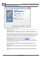
below.
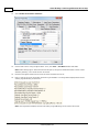
1. To start, locate the Function File Options tab in Device Properties. Then, select the Perform Block
Writes for Function Files Supporting Block Writes checkbox to notify the driver to utilize block
writes on function files that support block writes.
Note: Changes take effect on clicking OK or Apply.
www. kepware.com
Allen-Bradley ControlLogix Ethernet Driver Help
28
2. Next, write the desired value to the sub element tag in question. The sub element tag immediately takes
on the value written to it.
Note: After a sub element is written to at least once in block write mode, the tag's value does not originate
from the controller, but instead from the driver's write cache. After the block write is done, all sub
element tag values originate from the controller.
3. Once the entire desired sub elements are written to, perform the block write that sends these values to
the controller. To instantiate a block write, reference tag address RTC:<element>._SET. Setting this tag's
value to 'true' causes a block write to occur based on the current (last read) sub elements and the sub
elements affected (written to). Immediately after setting the tag to 'true', it is automatically reset to
"false." This is the default state and performs no action.
Applicable Function Files/Sub Elements
RTC
Year
YR
Month
MON
Day
DAY
Day of Week
DOW
Hour
HR
Minute
MIN
Second
SEC
See Also:
Function File Listing
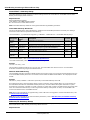
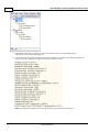
SLC 500 Slot Configuration
For I/O to be accessed, SLC5/01/02/03/04/05 models (modular I/O racks) must be configured for use with the
Allen-Bradley ControlLogix Ethernet Driver. Up to 30 slots can be configured per device.
Descriptions of the parameters are as follows:
l
Add: When clicked, this button inserts the selected module to the selected slot.
Note: Before adding a module, users must know the number of input and output words in each slot. This
www. kepware.com
Allen-Bradley ControlLogix Ethernet Driver Help
29
is necessary for the driver to correctly address the I/O. To address the I/O in a particular slot, all slots up
to and including that slot must be configured with I/O. For example, if a user is only interested in the I/O
in slot 3, the I/O for slots 1 and 2 must be configured.
l
Remove: When clicked, this button deletes the selected model from the selected slot.
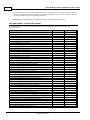
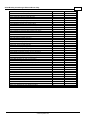
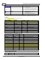
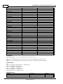
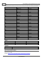
SLC 500 Modular I/O Selection Guide
The following table lists the number of input and output words available for each I/O module in the Slot
Configuration list.
Module Type
Input Words
Output Words
1746-I*8 Any 8 pt Discrete Input Module
1
0
1746-I*16 Any 16 pt Discrete Input Module
1
0
1746-I*32 Any 32 pt Discrete Input Module
2
0
1746-O*8 Any 8 pt Discrete Output Module
0
1
1746-O*16 Any 16 pt Discrete Output Module
0
1
1746-O*32 Any 32 pt Discrete Output Module
0
2
1746-IA4 4 Input 100 / 120 VAC
1
0
1746-IA8 8 Input 100 / 120 VAC
1
0
1746-IA16 16 Input 100/120 VAC
1
0
1746-IB8 8 Input (Sink) 24 VDC
1
0
1746-IB16 16 Input (Sink) 24 VDC
1
0
1746-IB32 32 Input (Sink) 24 VDC
2
0
1746-IG16 16 Input [TTL] (Source) 5 VDC
1
0
1746-IM4 4 Input 200 / 240 VAC
1
0
1746-IM8 8 Input 200 / 240 VAC
1
0
1746-IM16 16 Input 200/240 VAC
1
0
1746-IN16 16 Input 24 VAC / VDC
1
0
1746-ITB16 16 Input [Fast] (Sink) 24 VDC
1
0
1746-ITV16 16 Input [Fast] (Source) 24 VDC
1
0
1746-IV8 8 Input (Source) 24 VDC
1
0
1746-IV16 16 Input (Source) 24 VDC
1
0
1746-IV32 32 Input (Source) 24 VDC
2
0
1746-OA8 8 Output (TRIAC) 100 / 240 VAC
0
1
1746-OA16 16 Output (TRIAC) 100 / 240 VAC
0
1
1746-OB8 8 Output [Trans] (Source) 10 / 50 VDC
0
1
1746-OB16 16 Output [Trans] (Source) 10 / 50 VDC
0
1
1746-OB32 32 Output [Trans] (Source) 10/50 VDC
0
2
1746-OBP16 16 Output [Trans 1 Amp] (SRC) 24 VDC
0
1
1746-OV8 8 Output [Trans] (Sink) 10/50 VDC
0
1
1746-OV16 16 Output [Trans] (Sink) 10/50 VDC
0
1
1746-OV32 32 Output [Trans] (Sink) 10/50 VDC
0
2
1746-OW4 4 Output [Relay] VAC/VDC
0
1
1746-OW8 8 Output [Relay] VAC/VDC
0
1
1746-OW16 16 Output [Relay] VAC/VDC
0
1
1746-OX8 8 Output [Isolated Relay] VAC/VDC
0
1
1746-OVP16 16 Output [Trans 1 Amp] (Sink) 24 VDC3
0
1
1746-IO4 2 In 100 / 120 VAC 2 Out [Rly] VAC / VDC3
1
1
1746-IO8 4 In 100 / 120 VAC 4 Out [Rly] VAC / VDC4
1
1
1746-IO12 6 In 100 / 120 VAC 6 Out [Rly] VAC / VDC
1
1
1746-NI4 4 Ch Analog Input
4
0
1746-NIO4I Analog Comb 2 in & 2 Current Out
2
2
1746-NIO4V Analog Comb 2 in & 2 Voltage Out
2
2
1746-NO4I 4 Ch Analog Current Output
0
4
www. kepware.com
Allen-Bradley ControlLogix Ethernet Driver Help
30
1746-NO4V 4 Ch Analog Voltage Output
0
4
1746-NT4 4 Ch Thermocouple Input Module
8
8
1746-NR4 4 Ch Rtd / Resistance Input Module
8
8
1746-HSCE High-Speed Counter/Encoder
8
1
1746-HS Single Axis Motion Controller
4
4
1746-OG16 16 Output [TLL] (SINK) 5 VDC
0
1
1746-BAS Basic Module 500 5/01 Configuration
8
8
1746-BAS Basic Module 5/02 Configuration
8
8
1747-DCM Direct Communication Module (1/4 Rack)
2
2
1747-DCM Direct Communication Module (1/2 Rack)
4
4
1747-DCM Direct Communication Module (3/4Rack)
6
6
1747-DCM Direct Communication Module (Full Rack)
8
8
1747-SN Remote I/O Scanner
32
32
1747-DSN Distributed I/O Scanner 7 Blocks
8
8
1747-DSN Distributed I/O Scanner 30 Blocks
32
32
1747-KE Interface Module, Series A
1
0
1747-KE Interface Module, Series B
8
8
1746-NI8 8 Ch Analog Input, Class 1
8
8
1746-NI8 8 Ch Analog Input, Class 3
16
12
1746-IC16 16 Input (Sink) 48 VDC
1
0
1746-IH16 16 Input [Trans] (Sink) 125 VDC
1
0
1746-OAP12 12 Output [Triac] 120/240 VDC
0
1
1746-OB6EI 6 Output [Trans] (Source) 24 VDC
0
1
1746-OB16E 16 Output [Trans] (Source) Protected
0
1
1746-OB32E 32 Output [Trans] (Source) 10 / 50 VDC
0
2
1746-OBP8 8 Output [Trans 2 amp] (Source) 24 VDC
0
1
1746-IO12DC 6 Input 12 VDC, 6 Output [Rly]
1
1
1746-INI4I Analog 4 Ch. Isol. Current Input
8
8
1746-INI4VI Analog 4 Ch. Isol. Volt./Current Input
8
8
1746-INT4 4 Ch. Isolated Thermocouple Input
8
8
1746-NT8 Analog 8 Ch Thermocouple Input
8
8
1746-HSRV Motion Control Module
12
8
1746-HSTP1 Stepper Controller Module
8
8
1747-MNET MNET Network Comm Module
0
0
1747-QS Synchronized Axes Module
32
32
1747-QV Open Loop Velocity Control
8
8
1747-RCIF Robot Control Interface Module
32
32
1747-SCNR ControlNet SLC Scanner
32
32
1747-SDN DeviceNet Scanner Module
32
32
1394-SJT GMC Turbo System
32
32
1203-SM1 SCANport Comm Module - Basic
8
8
1203-SM1 SCANport Comm Module - Enhanced
32
32
AMCI-1561 AMCI Series 1561 Resolver Module
8
8
www. kepware.com
Allen-Bradley ControlLogix Ethernet Driver Help
31
Performance Optimizations
Although the Allen-Bradley ControlLogix Ethernet Driver is fast, a few guidelines may be applied to optimize the
application and gain maximum performance.
For more information on optimization at the communication and application levels, select a link from the list
below.
Optimizing Your Communications
Optimizing Your Application
Performance Statistics and Tuning
Performance Tuning Example
Optimizing Communications
As with any programmable controller, there are a variety of ways to enhance the performance and system
communications.
Protocol Mode
The Protocol Mode determines how Logix tag data is accessed from the controller. There are three types of
protocol modes: Symbolic, Logical Non-Blocking and Logical Blocking. Descriptions are as follows:
l
l
l
Symbolic Mode: Each client/server tag address is represented in the packet by its ASCII character
name.
Logical Non-Blocking Mode: Each client/server tag is represented by its logical memory address in the
PLC.
Logical Blocking Mode: The Logix tag is accessed as a single chunk of data. Each client/server tag
(such as MYTIMER.ACC) has a corresponding Logix tag (MYTIMER). Many client/server tags can belong to
the same Logix tag, as in the case of structures. On every read cycle, the Logix tag is read, its block is
updated in the driver cache and all client/server tags are updated from this cache.
Logical Non-Blocking Mode is generally recommended because it is the most efficient mode for gathering and
processing Logix tag data. Symbolic Mode is recommended for backward compatibility, whereas Logical NonBlocking Mode is recommended for projects containing a small number of references to UDT and/or predefined
structure Logix tags. Although Logical Blocking Mode can be efficient, it can also hurt performance if used
incorrectly. For more information on each mode's benefits and detriments, refer to Choosing a Protocol Mode.
www. kepware.com
Allen-Bradley ControlLogix Ethernet Driver Help
32
Tag Division Tips
Users should designate one or more devices for Logical Blocking purposes and one or more devices for Logical
Non-Blocking purposes. This improves performance because different tags in a project are often better suited for
different modes. When utilizing tag division, users should do the following:
1. Assign server tags referencing Atomic Logix tags (array or non-array) to the Logical Non-Blocking device.
2. Assign server tags referencing a Structure Logix tag composed of one-third* or less of the Structure tag
to the Logical Non-Blocking device(s). For example, if there are 55** or less member tags referencing a
PID_ENHANCED Logix tag, all these tags should be assigned to the Logical Non-Blocking device.
3. Assign server tags referencing a Structure Logix tag composed of one-third* or more of the Structure tag
to the Logical Blocking device(s). For example, if there are more than 55** member tags referencing a
PID_ENHANCED Logix tag, all of those tags should be assigned to the Logical Blocking device.
*One-third is not an exact limit, but rather a figure that has held true in a number of studies.
**A PID_ENHANCED structure has 165 tags, so one-third equals 55 tags.
Connection Size
Increasing the Connection Size allows more read/write requests per data packet, which provides greater
throughput. Although it also increases the CPU load and response turnaround time, it significantly improves
performance. The Connection Size parameter may be modified in the ControlLogix 5500 and CompactLogix 5300
device models only. For more information, refer to Logix Communications Parameters.
UDT Substructure Aliasing
If a UDT contains large substructures and one-third or more of the substructure members are referenced in the
client, refer to the following instructions to optimize reads for the substructure.
1. Create an alias of the substructure in RSLogix 5000. Then, assign server tags referencing the rest of the
UDT substructure to a Logical Blocking device.
2. Next, assign the server tags referencing the rest of the UDT (but not the substructure) to a Logical NonBlocking device.
System Overhead Time Slice
The System Overhead Time Slice (SOTS) is the percentage of time allocated to perform communication tasks
(such as OPC driver communications) that is set in RSLogix 5000. 100% SOTS is the percentage of time for
controller tasks (such as ladder logic). The default SOTS is 10%. In every 10 ms program scan that occurs, the
controller spends 1 ms processing Allen-Bradley ControlLogix Ethernet Driver requests (if the controller has a
continuous task). The value of SOTS defines the task's priority. If controller tasks are a high priority, the SOTS
should be set below 30%. If the communication tasks are high priority, the SOTS should be set at or above 30%.
For the best balance of communications performance and CPU utilization, set the SOTS to 10% to 40%.
Multi-Request Packets
The Allen-Bradley ControlLogix Ethernet Driver has been designed to optimize reads and writes. For non-array,
non-string tags (which only request one element), requests are blocked into a single transaction. This provides
drastic improvement in performance over single tag transactions. The only limitation is the number of data bytes
that can fit in a single transaction.
Important: In Symbolic Mode, each tag's ASCII string value is inserted into the request packet until no more tag
requests fit. For optimum performance, users should keep the tag names' size to a minimum. The smaller the tag
name, the more tags that fit in a single transaction and the fewer transactions needed to process all tags.
Array Elements Blocked (Symbolic and Logical Non-Blocking Modes Only)
To optimize the reading of atomic array elements, read a block of the array in a single request instead of
individually. The more elements read in a block, the greater the performance. Since transaction overhead and
processing consumes the most time, do as few transactions as possible while scanning as many desired tags as
possible. This is the essence of array element blocking.
Block sizes are specified as an element count. A block size of 120 elements means that a maximum of 120 array
elements are read in one request. The maximum block size is 3840 elements. Boolean arrays are treated
differently: in protocol, a Boolean array is a 32-bit array. Thus, requesting element 0 is requesting bits 0 through
31. To maintain consistency in discussion, a Boolean array element is considered a single bit. In summary, the
maximum number of array elements (based on block size of 3840) that can be requested is as follows:122880
BOOL, 3840 SINT, 3840 INT, 3840 DINT and 3840 REAL. www. kepware.com
Allen-Bradley ControlLogix Ethernet Driver Help
33
As discussed in Logix Communication Parameters, the block size is adjustable and should be chosen based
on the project at hand. For example, if array elements 0-26 and element 3839 are tags to be read, then using a
block size of 3840 is not only overkill, but detrimental to the driver's performance. This is because all elements
between 0 and 3839 are read on each request, even though only 28 of those elements are of importance. In this
case, a block size of 30 is more appropriate. Elements 0-26 would be serviced in one request and element 3839
would be serviced on the next.
Optimizing Strings
In the Logical Addressing modes, a write to STRING.DATA also writes to STRING.LEN with the proper length
value.
Automatically Read String Length
In this driver, string tags are structures with separate character data and length components. As such, the
driver automatically reads a string tag in two transactions: one in Logical Protocol Mode for the string character
data (DATA) and one in Symbolic Mode for the string length (LEN). When the "Automatically Read String Length"
option is unchecked, a single transaction is made to read the string character data. In this case, the Symbolic
Mode read for string length is bypassed. In a project with many string tags, this can significantly reduce the time
required to read all tags.
Note: For more information on the "Automatically Read String Length" option, refer to Logix Options.
Optimizing the Application
The Allen-Bradley ControlLogix Ethernet Driver has been designed to provide the best performance with the least
amount of impact on the system's overall performance. While the Allen-Bradley ControlLogix Ethernet Driver is
fast, there are a couple of guidelines that can be used to optimize the application and gain maximum
performance.
The server refers to communications protocols like Allen-Bradley ControlLogix Ethernet as a channel. Each
channel defined in the application represents a separate path of execution in the server. Once a channel has been
defined, a series of devices must then be defined under that channel. Each of these devices represents a single
Allen-Bradley Logix CPU from which data is collected. While this approach to defining the application provides a
high level of performance, it doesn't take full advantage of the Allen-Bradley ControlLogix Ethernet Driver or the
network. An example of how the application may appear when configured using a single channel is shown below.
Each device appears under a single channel, called "CLEthernet_
Channel1". In this configuration, the driver moves from one device to
the next as quickly as possible to gather information at an effective
rate. As more devices are added or more information is requested
from a single device, the overall update rate begins to suffer.
If the Allen-Bradley ControlLogix Ethernet Driver could only define a single channel, the example above would be
the only option available; however, the Allen-Bradley ControlLogix Ethernet Driver can define up to 1024
channels. Using multiple channels distributes the data collection workload by simultaneously issuing multiple
requests to the network. An example of how the same application may appear when configured using multiple
channels to improve performance is shown below.
www. kepware.com
Allen-Bradley ControlLogix Ethernet Driver Help
34
Each device has now been defined under its own channel. In this new
configuration, a single path of execution is dedicated to the task of
gathering data from each device. If the application has fewer devices,
it can be optimized as shown here.
The performance improves even if the application has more devices.
While fewer devices may be ideal, the application still benefits from
additional channels. Although by spreading the device load across all
channels causes the server to move from device to device again, it can
now do so with far less devices to process on a single channel.
Performance Statistics and Tuning
The Performance Statistics feature provides benchmarks and statistics about the Allen-Bradley ControlLogix
Ethernet application's performance. Because Performance Statistics is an additional layer of processing, it can
affect the server's performance. As such, the default setting is off. To enable the Performance Statistics feature,
open Device Properties and select the Logix Options tab. Then, check the Enable Performance Statistics
box.
Types of Performance Statistics
Performance Statistics provide meaningful numerical results across three scopes: device, channel, and driver.
Descriptions of the types are as follows:
l
l
l
Device: These statistics provide the data access performance on a particular device.
Channel: These statistics provide the average data access performance for all the devices under a given
channel with Performance Statistics enabled.
Driver: These statistics provide the average data access performance for all devices using the AllenBradley ControlLogix Ethernet Driver with Performance Statistics enabled.
Choosing a Statistic Type
The type of statistics needed depends on the application. In general, driver statistics provide a true measure of
the application's performance, whereas channel and device statistics are most relevant while tuning the
application. For example, will moving 10 certain tags from Device A to Device B increase the performance of
Device A? Will moving Device A from Channel 1 to Channel 2 increase the performance of Channel 1? These
questions are good examples of situations when device and channel statistics should be used.
Locating Statistics
Server statistics are output to the server's Event Log on shutdown. To view the results, shut down the server and
restart it.
Differences Between Server Statistics and Performance Statistics
Performance Statistics provide the makeup of the types of reads performed (such as symbolic vs. symbol
instance vs. physical, or device reads vs. cache reads) whereas server statistics provide a general read count
value.
Tuning the Application for Increased Performance
For information on increasing device and channel statistic results, refer to the instructions below. For more
information, refer to Optimizing Your Communications.
1. Server tags referencing Atomic Logix tags (array or non-array) should be assigned to Logical NonBlocking devices.
2. Server tags referencing a Structure Logix tag composed of one-third or less of the Structure tag should
be assigned to Logical Non-Blocking devices.
www. kepware.com
Allen-Bradley ControlLogix Ethernet Driver Help
35
3. Server tags referencing a Structure Logix tag composed of one-third or more of the Structure tag should
be assigned to Logical Blocking devices.
4. If Symbolic Mode is used, Logix names should be kept to a minimum length.
5. Logix arrays should be used as often as possible.
6. Only the necessary amount of System Overhead Time Slice for Ladder Logic/FBD should allocated to leave
the rest for driver communications.
7. For projects that read a large number of string tags in Logical Mode, uncheck the "Automatically Read
String Length" option located in the Logix Options tab of Device Properties.
For information on increasing driver statistic results, refer to the instructions below. For more information, refer
to Optimizing Your Application.
1. Devices should be spread across channels. More than one device should not be put on a channel unless
necessary.
2. Load should be spread evenly across devices. A single device should not be overloaded unless necessary.
3. The same Logix tag should not be referenced across different devices.
Note: Although these general rules can help optimize performance, it ultimately depends on the application. The
scan rate can obscure results: if tag requests are light, read and write transactions can complete before the next
request comes in. In this case, Logical Blocking and Logical Non-Blocking will have the same Performance
Statistics results. If tag requests are high (many tags or high scan rates), transaction completion time may take
longer. This is when the strengths and weaknesses of Logical Blocking and Logical Non-Blocking become
apparent. Performance Statistics can help tune the application for maximum performance. For an example, refer
to Performance Tuning Example.
Performance Tuning Example
Statistics can be applied to any application. In the example below, the Quick Client is used in the performance
tuning process. The idea is that all the tags used in the project are read at the same time at a fast scan rate.
Although this is not realistic, it does provide an accurate benchmark to the project layout in the server (tags
belonging to specific devices, devices belonging to specific channels, and so forth).
The statistics gathered are relative. Users should start with a server project layout, gather the statistics, and
then tune. It is recommended that more than one trial be used to properly assess the results for a given layout.
Once the most efficient layout is determined, the client application can be built with reassurance that the server
is optimal.
Caution: Performance results obtained using the Quick Client do not equate to performance results obtained
using a client application: several factors produce discrepancies. Although performance tuning with the client
application is more accurate than with the Quick Client, the tuning required not only affects the server project,
but the client application as well. It is recommended that the Quick Client be used to tune the application before
the client application is developed.
Note: The tuning process described below assumes that all tags are being read at a fast scan rate. Writes hinder
the performance.
1. In the controller project displayed below, there are the following:
2
1
1
1
1
Atomics
Atomic Array
UDT
UDT Array
Pre-Defined Type
Note: Overhead Time Slice (OTS) = 10%.
www. kepware.com
Allen-Bradley ControlLogix Ethernet Driver Help
36
2. After performing Automatic Tag Database Generation from this controller, the server produces the
following project.
Note: The "Global" tag group contains 130 tags.
3. To illustrate the benefits of tag division, this example does not reference all tags. More than one-third of
the ProcessPID tags, less than one-third of the FlowRates tags, and all other tags are referenced. As such,
the new tag count is 105.
4. Next, prepare the client for the test. To do so, launch the Quick Client from the server application by
clicking on the icon as shown below.
www. kepware.com
Allen-Bradley ControlLogix Ethernet Driver Help
37
5. Once the project is loaded, remove all groups except those containing tags of interest. Statistics and
System tags, for example, are not needed.
Note: For small projects, set the Group Update Rate to 0-10 ms. For large projects, set the rate to 1050 ms.
6. Next, click Tools | Test Mode.
7. Then, select Test 8. Activate items on start. Deactivate items on stop and then set a test interval.
Note: Since this project is fairly small, the interval has been set to 2 minutes. For larger projects, the
interval should be increased to get a more accurate reading.
www. kepware.com
Allen-Bradley ControlLogix Ethernet Driver Help
8. Next, click to select Enable.
9. Return to Tools | Test Mode and then disable test mode. All tags should be deactivated.
10. Disconnect the Quick Client so that time trials can begin.
11. Shutdown the server.
12. Next, launch the server and set the Protocol Mode to Logical Blocking. This is the default setting.
www. kepware.com
38
Allen-Bradley ControlLogix Ethernet Driver Help
39
13. Select Enable Performance Statistics.
14. Connect to the server using the Quick Client. Then, click Tools | Test Mode. Enable Test Mode.
Note: Data reading begins. When the test interval expires, all tags are deactivated and the driver ceases
statistics gathering. The results can then be viewed.
15. Disconnect the Quick Client from the server and then shutdown the server.
16. Next, re-launch the server and search its Event Log for statistics. The image below displays the first trial
utilizing Logical Blocking for the device.
Note: The image below displays the first trial utilizing Logical Blocking for the channel and driver.
www. kepware.com
Allen-Bradley ControlLogix Ethernet Driver Help
40
Note: This is the control set for comparisons.
17. In the server, set the Protocol Mode to Logical Non-Blocking.
18. Connect to the server using Quick Client. Then, click Tools | Test Mode and enable test mode.
Note: Data reading begins. When the test interval expires, all tags are deactivated and the driver ceases
statistics gathering. The results can then be viewed.
19. Disconnect the Quick Client from the server and then shutdown the server.
20. Next, re-launch the server and then search its Event Log for statistics. The image below displays the
second trial utilizing Logical Non-Blocking for the device.
Note: The image below displays the second trial utilizing Logical Non-Blocking for the channel and driver.
www. kepware.com
41
Allen-Bradley ControlLogix Ethernet Driver Help
21. From the server, set the Protocol Mode to Symbolic to see how the performance fared prior to AllenBradley ControlLogix Ethernet Driver version 4.6.0.xx.
22. Connect to the server using the Quick Client. Then, click Tools | Test Mode and enable test mode.
Note: Data reading begins. When the test interval expires, all tags are deactivated and the driver ceases
statistics gathering. The results can then be viewed.
23. Disconnect the Quick Client from the server and then shutdown the server.
24. Next, re-launch the server and search its Event Log for statistics. The image below displays the third trial
utilizing Symbolic for the device.
The image below displays the third trial utilizing Symbolic for the channel and driver.
www. kepware.com
Allen-Bradley ControlLogix Ethernet Driver Help
Note: It appears that Logical Blocking is most optimal for the given application.
Optimizing Channel Communications
Channel communications can be optimized by moving tags for Logical Blocking in one device and tags for Logical
Non-Blocking in another. This is called tag division.
Logical Blocking (Device 1)
ProcessPID
OverflowCounter
Logical Non-Blocking (Device 2)
FlowRate
ValveOpen
InProcess
Tank Volume
www. kepware.com
42
43
Allen-Bradley ControlLogix Ethernet Driver Help
1. Repeat Steps 4 through 15. In Step 11, make sure that Device 1 is Logical Blocking and Device 2 is Logical
Non-Blocking.
2. Launch the server and search the server Event Log for statistics. The image below displays the fourth trial
utilizing tag division for the device.
Note: The image below displays the fourth trial utilizing tag division for the channel and driver.
www. kepware.com
Allen-Bradley ControlLogix Ethernet Driver Help
Note: The individual device statistics do not look impressive because the two devices are running on separate
statistic counters. The key to this test is that the channel and driver statistics are better (6126) than using one
channel/one device with either Logical Blocking (5972) or Logical Non-Blocking (3705).
Optimize Application
The application can be optimized by moving Device 1 to one channel and Device 2 to another.
Logical Blocking (Channel1.Device 1
ProcessPID
OverflowCounter
Logical Non-Blocking (Channel2.Device 2)
FlowRate
ValveOpen
InProcess
Tank Volume
www. kepware.com
44
45
Allen-Bradley ControlLogix Ethernet Driver Help
1. Repeat Steps 4 through 15. In Step 11, make sure Channel1.Device 1 is Logical Blocking and
Channel2.Device 2 is Logical Non-Blocking.
2. Launch the server and search the server Event Log for statistics. The image below displays the fifth trial
utilizing Logix tag coupled with multiple channels for Channel 1.Device1.
Note: The image below displays the fourth trial utilizing Logix tag for Channel2.Device2.
www. kepware.com
Allen-Bradley ControlLogix Ethernet Driver Help
46
Note: The image below displays the fourth trial utilizing tag division for the driver.
Results
Driver Performance
(Reads/Second)
Improvement
Over Symbolic
Single Channel
Single Device with Logical Blocking
5972
768%
Single Channel
Single Device with Logical Non-Blocking
3705
476%
Single Channel
Single Device with Symbolic
777
N/A
Single Channel
Multiple Devices with Tag Division
6126
788%
Multiple Channels
Multiple Devices with Tag Division
6426
827%
Server Project Layout
Conclusions
The project began with a single channel and a single device, which is the default behavior for a single controller.
All tags were imported from this controller to this channel.device. All three protocol modes were then tested to
see which would provide the best performance. In this case, Logical Blocking Protocol was the best. The best
protocol depends on the application at hand. When performance is crucial, it is worth performing Logical
www. kepware.com
47
Allen-Bradley ControlLogix Ethernet Driver Help
Blocking and Logical Non-Blocking trials to determine which is the best protocol mode for the application.
Symbolic protocol is not necessary because it never meets the performance caliber of either of the other protocol
modes. It is shown here for the sake of the example.
Measures were taken to optimize communications using the tips outlined in Optimizing Your
Communications. Most notably, tag division was used to place the Logical Blocking type tags in a device
assigned Logical Blocking and the Logical Non-Blocking type tags in a device assigned Logical Non-Blocking.
Furthermore, both devices resided on the same channel. The results show an improvement over using Logical
Blocking on a single device. This is because some tags lend themselves better to one protocol mode over another.
For example, reading an entire COUNTER benefits from Logical Blocking over Logical Non-Blocking since it's much
faster reading the COUNTER as a block then as individual members.
Measures were also taken to optimize the application by placing devices on their own channel. Using the devices
created in the previous trial, a Logical Blocking device was placed on one channel and a Logical Non-Blocking
device on another. The results show improvement over the single channel/multiple devices scenario from the
previous trial. This reinforces the idea that performance is improved by having as few devices per channel and as
many channels as necessary.
After using these three optimization methods, the project has an 827% performance increase over Allen-Bradley
ControlLogix Ethernet Driver version earlier than 4.6.0.xx. Tag division and multiple channels improved the
performance by 107%. The performance increases is more apparent with larger projects.
www. kepware.com
Allen-Bradley ControlLogix Ethernet Driver Help
Data Types Description
Data Types
Description
Boolean
Single bit
Byte
Unsigned 8-bit value
Char
Signed 8-bit value
Word
Unsigned 16-bit value
Short
Signed 16-bit value
DWord
Unsigned 32-bit value
Long
Signed 32-bit value
BCD
Two byte packed BCD, four decimal digits
LBCD
Four byte packed BCD, eight decimal digits
Float
32-bit IEEE floating point
Double
64-bit IEEE floating point
Date
64-bit Date/Time
String
Null terminated character array
Note: For a description of Logix platform-specific data types, refer to Logix Advanced Addressing.
www. kepware.com
48
Allen-Bradley ControlLogix Ethernet Driver Help
49
Address Descriptions
Address specifications vary depending on the model in use. For the model of interest's address information, refer
to the table below.
Protocol Class
Models
Help Link
Logix-Ethernet
ControlLogix 5500 Ethernet, CompactLogix
5300, Ethernet, FlexLogix 5400 Ethernet,
SoftLogix 5800
Logix Addressing
DH+ Gateway
DH+ Gateway: PLC-5
DH+ Gateway: SLC 5/04
PLC-5 Series Addressing
SLC 500 Modular I/O Addressing
ControlNet Gateway
ControlNet Gateway: PLC-5C
PLC-5 Series Addressing
1761-NET-ENI
ENI: ControlLogix 5500, ENI: CompactLogix
5300, ENI: FlexLogix 5400
Logix Addressing
ENI: MicroLogix
ENI: SLC 500 Fixed I/O
ENI: SLC 500 Modular I/O
ENI: PLC-5
MicroLogix Addressing
SLC 500 Fixed I/O Addressing
SLC 500 Modular I/O Addressing
PLC-5 Series Addressing
MicroLogix 1100
Ethernet
MicroLogix 1100
MicroLogix Addressing
MicroLogix 1400
Ethernet
MicroLogix 1400
MicroLogix Addressing
Note: For more information on the controller's pre-defined data types, refer to the device's documentation.
Logix Addressing
For more information on these models' tag-based addressing and relationship to the Allen-Bradley ControlLogix
Ethernet Driver, refer to Logix Tag-Based Addressing.
ControlLogix 5500 Addressing for Ethernet
ControlLogix is a member of the Logix family and part of Rockwell Automation's Integrated Architecture. This
means it uses a tag or symbol-based addressing structure. Logix tags differ from conventional PLC data items in
that the tag name itself is the address, not a physical or logical address.
ControlLogix 5500 Addressing for ENI
ControlLogix is a member of the Logix family and part of Rockwell Automation's Integrated Architecture. This
means it uses a tag or symbol-based addressing structure. Logix tags differ from conventional PLC data items in
that the tag name itself is the address, not a physical or logical address.
ControlLogix 5500 Addressing for Serial Gateway
ControlLogix is a member of the Logix family and part of Rockwell Automation's Integrated Architecture. This
means it uses a tag or symbol-based addressing structure. Logix tags differ from conventional PLC data items in
that the tag name itself is the address, not a physical or logical address.
CompactLogix 5300 Addressing for Ethernet
CompactLogix is a member of the Logix family and part of Rockwell Automation's Integrated Architecture. This
means it uses a tag or symbol-based addressing structure. Logix tags differ from conventional PLC data items in
that the tag name itself is the address, not a physical or logical address.
CompactLogix 5300 Addressing for ENI
CompactLogix is a member of the Logix family and part of Rockwell Automation's Integrated Architecture. This
means it uses a tag or symbol-based addressing structure. Logix tags differ from conventional PLC data items in
that the tag name itself is the address, not a physical or logical address.
CompactLogix 5300 Addressing for Serial Gateway
CompactLogix is a member of the Logix family and part of Rockwell Automation's Integrated Architecture. This
means it uses a tag or symbol-based addressing structure. Logix tags differ from conventional PLC data items in
that the tag name itself is the address, not a physical or logical address.
FlexLogix 5400 Addressing for Ethernet
www. kepware.com
Allen-Bradley ControlLogix Ethernet Driver Help
50
FlexLogix is a member of the Logix family and part of Rockwell Automation's Integrated Architecture. This means
it uses a tag or symbol-based addressing structure. Logix tags differ from conventional PLC data items in that the
tag name itself is the address, not a physical or logical address.
FlexLogix 5400 Addressing for ENI
FlexLogix is a member of the Logix family and part of Rockwell Automation's Integrated Architecture. This means
it uses a tag or symbol-based addressing structure. Logix tags differ from conventional PLC data items in that the
tag name itself is the address, not a physical or logical address.
FlexLogix 5400 Addressing for Serial Gateway
FlexLogix is a member of the Logix family and part of Rockwell Automation's Integrated Architecture. This means
it uses a tag or symbol-based addressing structure. Logix tags differ from conventional PLC data items in that the
tag name itself is the address, not a physical or logical address.
SoftLogix 5800 Addressing
SoftlLogix is a member of the Logix family and part of Rockwell Automation's Integrated Architecture. This means
it uses a tag or symbol-based addressing structure. Logix tags differ from conventional PLC data items in that the
tag name itself is the address, not a physical or logical address.
SoftLogix 5800 Addressing for Serial Gateway
SoftlLogix is a member of the Logix family and part of Rockwell Automation's Integrated Architecture. This means
it uses a tag or symbol-based addressing structure. Logix tags differ from conventional PLC data items in that the
tag name itself is the address, not a physical or logical address.
MicroLogix Addressing
MicroLogix Addressing for Ethernet/IP Gateway
The actual number of addresses available depends on the model of the PLC. The ranges have been opened up to
allow for maximum flexibility with future models. If the driver finds at Runtime that an address is not present in
the device, it posts an error message and then removes the tag from its scan list. For more information on filespecific addressing, select a link from the list below.
Output Files
Input Files
Status Files
Binary Files
Timer Files
Counter Files
Control Files
Integer Files
Float Files
ASCII Files
String Files
Long Files
MicroLogix PID Files
MicroLogix Message Files
For information on function files, select a link from the list below.
High-Speed Counter File (HSC)
Real-Time Clock File (RTC)
Channel 0 Communication Status File (CS0)
Channel 1 Communication Status File (CS1)
I/O Module Status File (IOS)
MicroLogix Addressing for ENI
The actual number of addresses available depends on the model of the PLC. The ranges have been opened up to
allow for maximum flexibility with future models. If the driver finds at Runtime that an address is not present in
the device, it posts an error message and then removes the tag from its scan list. For more information on filespecific addressing, select a link from the list below.
Output Files
Input Files
Status Files
www. kepware.com
Allen-Bradley ControlLogix Ethernet Driver Help
51
Binary Files
Timer Files
Counter Files
Control Files
Integer Files
Float Files
ASCII Files
String Files
Long Files
MicroLogix PID Files
MicroLogix Message Files
For information on function files, select a link from the list below.
High-Speed Counter File (HSC)
Real-Time Clock File (RTC)
Channel 0 Communication Status File (CS0)
Channel 1 Communication Status File (CS1)
I/O Module Status File (IOS)
MicroLogix 1100 Addressing
The actual number of addresses available depends on the model of the PLC. The ranges have been opened up to
allow for maximum flexibility with future models. If the driver finds at Runtime that an address is not present in
the device, it posts an error message and then removes the tag from its scan list. For more information on filespecific addressing, select a link from the list below.
Output Files
Input Files
Status Files
Binary Files
Timer Files
Counter Files
Control Files
Integer Files
Float Files
String Files
Long Files
MicroLogix PID Files
MicroLogix Message Files
For information on function files, select a link from the list below.
High-Speed Counter File (HSC)
Real-Time Clock File (RTC)
Channel 0 Communication Status File (CS0)
Channel 1 Communication Status File (CS1)
I/O Module Status File (IOS)
MicroLogix 1400 Addressing
The actual number of addresses available depends on the model of the PLC. The ranges have been opened up to
allow for maximum flexibility with future models. If the driver finds at Runtime that an address is not present in
the device, it posts an error message and then removes the tag from its scan list. For more information on filespecific addressing, select a link from the list below.
Output Files
Input Files
Status Files
Binary Files
Timer Files
Counter Files
Control Files
Integer Files
Float Files
www. kepware.com
Allen-Bradley ControlLogix Ethernet Driver Help
ASCII Files
String Files
Long Files
MicroLogix PID Files
MicroLogix Message Files
For information on function files, select a link from the list below.
High-Speed Counter File (HSC)
Real-Time Clock File (RTC)
Channel 0 Communication Status File (CS0)
Channel 1 Communication Status File (CS1)
I/O Module Status File (IOS)
SLC 500 Fixed I/O Addressing
SLC 500 Fixed I/O Addressing for Ethernet/IP Gateway
For more information on file-specific addressing, select a link from the list below.
Output Files
Input Files
Status Files
Binary Files
Timer Files
Counter Files
Control Files
Integer Files
SLC 500 Fixed I/O Addressing for ENI
For more information on file-specific addressing, select a link from the list below.
Output Files
Input Files
Status Files
Binary Files
Timer Files
Counter Files
Control Files
Integer Files
SLC 500 Modular I/O Addressing
SLC 500 Modular I/O Addressing for DH+
The actual number of addresses available depends on the model of the PLC. The ranges have been opened up to
allow for maximum flexibility with future models. If the driver finds at Runtime that an address is not present in
the device, it posts an error message and then removes the tag from its scan list. For more information on filespecific addressing, select a link from the list below.
Output Files
Input Files
Status Files
Binary Files
Timer Files
Counter Files
Control Files
Integer Files
Float Files
ASCII Files
String Files
SLC 500 Modular I/O Addressing for Ethernet/IP Gateway
The actual number of addresses available depends on the model of the PLC. The ranges have been opened up to
allow for maximum flexibility with future models. If the driver finds at Runtime that an address is not present in
www. kepware.com
52
Allen-Bradley ControlLogix Ethernet Driver Help
53
the device, it posts an error message and then removes the tag from its scan list. For more information on filespecific addressing, select a link from the list below.
Output Files
Input Files
Status Files
Binary Files
Timer Files
Counter Files
Control Files
Integer Files
Float Files
ASCII Files
String Files
SLC 500 Modular I/O Addressing for ENI
The actual number of addresses available depends on the model of the PLC. The ranges have been opened up to
allow for maximum flexibility with future models. If the driver finds at Runtime that an address is not present in
the device, it posts an error message and then removes the tag from its scan list. For more information on filespecific addressing, select a link from the list below.
Output Files
Input Files
Status Files
Binary Files
Timer Files
Counter Files
Control Files
Integer Files
Float Files
ASCII Files
String Files
PLC-5 Series Addressing
PLC-5 Series Addressing for ControlNet
For more information on file-specific addressing, select a link from the list below.
Output Files
Input Files
Status Files
Binary Files
Timer Files
Counter Files
Control Files
Integer Files
Float Files
ASCII Files
String Files
BCD Files
PID Files
Message Files
Block Transfer Files
PLC-5 Series Addressing for DH+
For more information on file-specific addressing, select a link from the list below.
Output Files
Input Files
Status Files
Binary Files
Timer Files
Counter Files
www. kepware.com
Allen-Bradley ControlLogix Ethernet Driver Help
54
Control Files
Integer Files
Float Files
ASCII Files
String Files
BCD Files
PID Files
Message Files
Block Transfer Files
PLC-5 Series Addressing for Ethernet/IP Gateway
For more information on file-specific addressing, select a link from the list below.
Output Files
Input Files
Status Files
Binary Files
Timer Files
Counter Files
Control Files
Integer Files
Float Files
ASCII Files
String Files
BCD Files
PID Files
Message Files
Block Transfer Files
PLC-5 Series Addressing for ENI
For more information on file-specific addressing, select a link from the list below.
Output Files
Input Files
Status Files
Binary Files
Timer Files
Counter Files
Control Files
Integer Files
Float Files
ASCII Files
String Files
BCD Files
PID Files
Message Files
Block Transfer Files
Logix Tag-Based Addressing
Rockwell Automation's Integrated Architecture uses a tag or symbol-based addressing structure that is
commonly referred to as Logix tags (or Native tags). These tags differ from conventional PLC data items in that
the tag name itself is the address, not a physical or logical address.
Note: Throughout this help file, Logix tags are assumed to be global in nature unless specified otherwise.
The Allen-Bradley ControlLogix Ethernet Driver allows users to access the controller's atomic data types: BOOL,
SINT, INT, DINT, LINT, and REAL. Although some of the pre-defined types are structures, they are ultimately
based on these atomic data types. Thus, all non-structure (atomic) members of a structure are accessible. For
example, a TIMER cannot be assigned to a server tag but an atomic member of the TIMER can be assigned to the
tag (such as TIMER.EN, TIMER.ACC, and so forth). If a structure member is a structure itself, both structures
would have to be expanded to access an atomic member of the substructure. This is more common with user and
module-defined types and is not found in any of the pre-defined types.
www. kepware.com
Allen-Bradley ControlLogix Ethernet Driver Help
55
Atomic Data
Type
Description
BOOL
Single-bit value
VT_
BOOL
0, 1
SINT
Signed 8-bit value
VT_UI1
-128 to 127
INT
Signed 16-bit value
VT_I2
-32,768 to 32,767
DINT
Signed 32-bit value
VT_I4
-2,147,483,648 to 2,147,483,647
LINT
Signed 64-bit value
VT_I8
–9,223,372,036,854,775,808 to
9,223,372,036,854,775,807
REAL
32-bit IEEE floating
point
VT_R4
1.1755 E-38 to 3.403E38, 0, -3.403E-38 to -1.1755
Range
See Also: Logix Advanced Addressing
Client/Server Tag Address Rules
Logix tag names correspond to client/server tag addresses. Logix tag names (entered via RSLogix5000) follow
the IEC 1131-3 identifier rules. Client/server tag addresses follow these same rules. They are as follows:
l
Must begin with an alphabetic (A-Z, a-z) character or an underscore (_).
l
Can only contain alphanumeric characters and underscores.
l
Can have as many as 40 characters.
l
Cannot have consecutive underscores.
l
Are not case sensitive.
Client/Server Tag Name Rules
Tag name assignment in the server differs from address assignment in that names cannot begin with an
underscore.
Note: Logix tag names should be kept to a minimum in size for optimum performance. The smaller the name, the
more requests that are able fit in a single transaction.
Important: Symbolic Mode users should keep the client/server tag addresses below 400 characters. For
example, tagarray[1,2,4].somestruct.substruct_array[3].basetag.[4] is 57 characters in length. Since a packet
can only hold 500 data bytes, any overhead bytes that need to be added to the packet can greatly diminish the
room available to the characters themselves. By keeping the address below 400, the tag request remains
complete and valid.
See Also:Performance Optimizations
Address Formats
There are several ways to address a Logix tag statically in the server or dynamically from a client. The format
used depends on the type and usage of the tag. For example, the bit format would be used when accessing a bit
within a SINT-type tag. For information on address format and syntax, refer to the table below.
Note: All formats except for Array and String are native to RSLogix5000. Therefore, when referencing an atomic
data type, an RSLogix 5000 tag name can be copied and pasted into the server's tag address field and be valid.
Format
Syntax
Example
Notes
Standard
<logix tag name>
tag_1
Tag cannot be an array.
Array
Element
<logix array tag
name> [dim 1,
dim2, dim 3]
tag_1 [2, 58,
547]
tag_1 [0, 3]
Dimension range = 1
to 3 | element range = 0 to 65535
Array
w/o
Offset*
<logix array tag
name> {#
columns}
<logix array tag
name> {# rows}{#
columns}
tag_1 {8}
tag_1 {2}{4}
Dimension range = 1 to 2 | element range = 1 to 65535
The number of elements to read/write equals # of rows
times # of columns. If no rows are specified, # of rows
default to 1.
The array begins at a zero offset (array index equals 0 for
all dimensions).
Array w/
Offset*
<logix array element tag_1 [2, 3]
tag> {# columns}
{10}
The array begins at an offset specified by the dimensions
in the array element tag. The array always covers the
www. kepware.com
Allen-Bradley ControlLogix Ethernet Driver Help
Bit
String
56
<logix array
element tag> {#
rows}{# columns}
tag_1 [2, 3]
2}{5}
highest dimension. Tag_1[2,3]{10} would produce an
array of elements tag_1[2,3] -> tag_1[2,13]
<logix tag
name>.bit
<logix tag name>.
[bit]
tag_1.0
tag_1.[0]
Bit range = 0 to 31
<logix tag
name>/<maximum
string length>
tag_1.Data/4
Stringtag_
1.Data
SINTarraytag_
1/16
If tag is an array, it must be a BOOL array, otherwise tag
cannot be an array.
Length range = 1 to 65535
The maximum number of characters that can read/write to
the string.
*Since this format may request more than one element, the order in which array data is passed depends on the
dimension of the Logix Array tag. For example, if rows times cols = 4 and the Controller tag is a 3X3 element
array, then the elements that are being referenced are array_tag [0,0], array_tag [0,1], array_tag [0,2], and
array_tag [1,0] in that exact order. The results would be different if the Controller tag were a 2X10 element
array.
Note: For more information on how elements are referenced for 1, 2 and 3 dimensional arrays, refer to Ordering
of Array Data.
Tag Scope
Global Tags
Global tags are Logix tags that have global scope in the controller. Any program or task can access Global tags;
however, the number of ways a Global tag can be referenced depends on its Logix data type and the address
format being used.
Program Tags
Program tags are identical to Global tags except that a Program tag's scope is local to the program in which it is
defined. Program tags follow the same addressing rules and limitations as Global tags, but are prefixed with the
following notation:
Program: <program name>.
For example, Logix tag "tag_1" in program "prog_1" would be addressed as "Program:prog_1.tag_1" in a
client/server tag address.
Structure Tag Addressing
Logix Structure tags (Global or Program) are tags with one or more member tags. Member tags can be atomic or
structured in nature.
<structure name>. <atomic-type tag>
This implies that a substructure would be addressed as:
<structure name> . <substructure name> .<atomic-type tag>
Arrays of structures would be addressed as:
<structure array name> [dim1, dim2, dim3] . <atomic-type tag>
This implies that an array of substructures would be addressed as:
<structure name> . <substructure array name> [dim1, dim2, dim3] . <atomic-type tag>
Note: The examples above are only a few of the addressing possibilities that involve structures, and are
displayed to provide an introduction to structure addressing. For more information, refer to Allen-Bradley or
Rockwell documentation.
Internal Tags
Internal tags are not visible in the server configuration, but can be browsed by the OPC client and found under
the <Channel Name>.<Device Name> group. The _CIPConnectionSizeRequested tag reflects the CIP connection
size that was requested. The _CIPConnectionSizeActual tag reflects the actual CIP connection size that is in use.
www. kepware.com
Allen-Bradley ControlLogix Ethernet Driver Help
57
Its value differ from the _CIPConnectionSizeRequested tag if the value requested is not supported by the device.
For more information on the connection size, refer to Logix Communications Parameters.
Note: The tags described in the table below are only valid for the ControlLogix 5500 and CompactLogix 5300
device models.
Type
Tag Name
Support
Access
System
Tag
_CIPConnectionSizeRequested
Logix models, with the exception of Serial
Gateway models.
Read/Write*
Status
Tag
_CIPConnectionSizeActual
Logix models, with the exception of Serial
Gateway models.
Read Only
*This tag is read only for ENI Logix models.
Changing the CIP connection size
The _CIPConnectionSizeRequested tag allows users to change the CIP connection size parameter in real time.
Both the connection size parameter (located in the Logix Comm. Parameters tab in Device Properties) and
the System tag are configurable while clients are connected. Changes are applied before the next read/Write
request is performed.
Predefined Term Tags
The tags displayed in the table below can be used to obtain general processor information from a PLC.
Tag Name
Description
#MODE
A description of the PLC's current key switch mode. Possible string values include
Program, Run, Remote Program, Remote Run, and Remote Debug. Supported data
types include string.
#PLCTYPE
An integer value that corresponds to the "ProdType" attribute specified in the PLC's
EDS file. Supported data types include all but string.
#REVISION
Firmware revision displayed as "<major>.<minor>". Supported data types include
string.
#PROCESSORNAME
The processor name that corresponds to the "ProdName" attribute specified in the
PLC's EDS file. Supported data types include string.
#STATUS
Indicates the PLC's status. Possible values include OK (1) and Faulted (0). Supported
data types include all but date.
#PRODUCTCODE
An integer value that corresponds to the "ProdCode" attribute specified in the PLC's
EDS file. Supported data types include all but string.
#VENDORID
An integer value that corresponds to the "VendCode" attribute specified in the PLC's
EDS file. Supported data types include all but string.
Addressing Atomic Data Types
Below are suggested usages and addressing possibilities for a Logix data type given the address formats
available. Examples are also given for reinforcement. Click on Advanced for advanced addressing possibilities
for the given atomic data type.
Note: Empty cells do not necessarily indicate a lack of support.
Atomic
Data Type
Standard Array Element Array with or
without Offset
Bit
String
Byte Array, Char Array
Boolean
String
(SINT 1/2/3 dimensional
array)
(Bit w/i
SINT)
(SINT 1/2/3
dimensional
BOOL
Client/Server
Data Type
Boolean
Advanced
Client/Server
Tag Example
BOOLTAG
Boolean
Boolean Array
(BOOL 1
dimensional
array)
(BOOL 1 dimensional array)
BOOLARR[0]
BOOLARR[0]{32}
SINT
Client/Server
Data Type
Advanced
Byte, Char Byte, Char
www. kepware.com
Allen-Bradley ControlLogix Ethernet Driver Help
58
array)
Client/Server
Tag Example
SINTTAG
SINTARR[0]
SINTARR[0]{4}
SINTTAG.0
SINTARR/4
Word,
Short
Word, Short
Word Array, Short Array
(INT 1/2/3 dimensional
array)
Boolean
*
INTTAG
INTARR[0]
INTARR[0]{4}
INTTAG.0
DWord,
Long
DWord, Long
DWord Array, Long Array
Boolean
INT
Client/Server
Data Type
(Bit w/i
INT)
Advanced
Client/Server
Tag Example
DINT
Client/Server
Data Type
(Bit w/i
DINT)
Advanced
Client/Server
Tag Example
**
DINTTAG
DINTARR[0]
DINTARR[0]{4}
Double,
Date
Double, Date
Double Array
LINTTAG
LINTARR[0]
LINTARR[0]{4}
Float
Float
Float Array
REALTAG
REALARR[0]
REALARR[0]{4}
DINTTAG.0
LINT
Client/Server
Data Type
Advanced
Client/Server
Tag Example
REAL
Client/Server
Data Type
***
***
Advanced
Client/Server
Tag Example
*See Also: Advanced Addressing INT.
**See Also: Advanced Addressing DINT.
***See Also: Advanced Addressing REAL.
Addressing Structure Data Types
Only the atomic structure members can be addressed at the structure level. For more information, refer to the
examples below.
Logix Tag
MyTimer @ TIMER
Client/Server Tag
1. Invalid
TimerTag address = MyTimer
TimerTag data type = ??
2. Valid
TimerTag address = MyTimer.ACC
TimerTag data type = DWord
Addressing STRING Data Type
STRING is a pre-defined Logix data type whose structure contains two members: DATA and LEN. DATA is an
array of SINTs and stores the characters of the STRING. LEN is a DINT and represents the number of characters
in DATA to display to a client.
Because LEN and DATA are atomic members, they must be referenced independently from a client/server. The
syntax is as shown below.
Description
Syntax
Example
www. kepware.com
Allen-Bradley ControlLogix Ethernet Driver Help
59
STRING Value
DATA/<Maximum STRING length >
MYSTRING.DATA/82
Actual STRING length
LEN
MYSTRING.LEN
Reads
The STRING read from DATA is terminated by the following:
a. The first null terminator encountered.
b. The value in LEN if a) doesn't occur first.
c. The <Maximum STRING length > if either a) or b) doesn't occur first.
Example
MYSTRING.DATA contains "Hello World" in the PLC, but LEN is manually set to 5. A read of MYSTRING.DATA/82
displays "Hello". If LEN is set to 20, MYSTRING.DATA/82 displays "Hello World".
Writes
When a STRING value is written to DATA, the driver also writes to LEN with the length of DATA written. If the
write to LEN fails for any reason, the write operation to DATA is considered failed as well (despite the fact that the
DATA write to the controller succeeded).
Note: This behavior was designed specifically for Logix tags of type STRING or a custom derivative of it. The
following precautions apply to users who wish to implement their own STRING in UDTs.
l
l
If a UDT exists that has a DATA member referenced as a STRING and a LEN member referenced as a DINT,
the write to LEN succeeds regardless of the intentions of LEN for the given UDT. Care must be taken when
designing UDTs to avoid this possibility if LEN is not intended to be the length of DATA.
If a UDT exists that has a DATA member referenced as a STRING but does not have a LEN member, the
write to LEN fails silently without consequence to DATA.
Example
MYSTRING.DATA/82 holds the value "Hello World." MYSTRING.LEN holds 11. If the value "Alarm Triggered" is
written to MYSTRING.DATA/82, 15 is written to MYSTRING.LEN. If the write to MYSTRING.LEN fails,
MYSTRING.LEN holds its previous value of 11 while MYSTRING.DATA/82 displays the first 11 characters ("Alarm
Trigg"). If the write to MYSTRING.DATA/82 fails, neither tag is affected.
Automatically Read String Length
In the logical addressing modes, reading STRING.DATA causes an automatic read of STRING.LEN in Symbolic
Mode. This may be bypassed by disabling the "Automatically Read String length" option. For more information,
refer to Logix Options.
Ordering of Logix Array Data
One-Dimensional Arrays - array [dim1]
One-dimensional array data is passed to and from the controller in ascending order.
for (dim1 = 0; dim1 < dim1_max; dim1++)
Example: 3 element array
array [0]
array [1]
array [2]
Two-Dimensional Arrays - array [dim1, dim2]
Two-dimensional array data is passed to and from the controller in ascending order.
for (dim1 = 0; dim1 < dim1_max; dim1++)
for (dim2 = 0; dim2 < dim2_max; dim2++)
Example: 3X3 element array
array [0, 0]
array [0, 1]
array [0, 2]
array [1, 0]
array [1, 1]
array [1, 2]
array [2, 0]
array [2, 1]
array [2, 2]
www. kepware.com
Allen-Bradley ControlLogix Ethernet Driver Help
60
Three-Dimensional Arrays - array [dim1, dim2, dim3]
Three-dimensional array data is passed to and from the controller in ascending order.
for (dim1 = 0; dim1 < dim1_max; dim1++)
for (dim2 = 0; dim2 < dim2_max; dim2++)
for (dim3 = 0; dim3 < dim3_max; dim3++)
Example: 3X3x3 element array
array [0, 0, 0]
array [0, 0, 1]
array [0, 0, 2]
array [0, 1, 0]
array [0, 1, 1]
array [0, 1, 2]
array [0, 2, 0]
array [0, 2, 1]
array [0, 2, 2]
array [1, 0, 0]
array [1, 0, 1]
array [1, 0, 2]
array [1, 1, 0]
array [1, 1, 1]
array [1, 1, 2]
array [1, 2, 0]
array [1, 2, 1]
array [1, 2, 2]
array [2, 0, 0]
array [2, 0, 1]
array [2, 0, 2]
array [2, 1, 0]
array [2, 1, 1]
array [2, 1, 2]
array [2, 2, 0]
array [2, 2, 1]
array [2, 2, 2]
Logix Advanced Addressing
Advanced Addressing is available for the following atomic data types. Select a link from the list below for more
information on a specific data type.
BOOL
SINT
INT
DINT
LINT
REAL
Advanced Addressing: BOOL
Format
Supported Data Types
Notes
Standard
Boolean
Byte, Char
Word, Short, BCD
DWord, Long, LBCD
Float*
None
Boolean
The Controller tag must be a one-dimensional
array.
Array w/o
Offset
Array w/o
Offset
Boolean Array
1. The Controller tag must be a onedimensional array.
Byte Array, Char Array
Word Array, Short Array, BCD Array
DWord Array, Long Array, LBCD
Array
2. The number of elements must be a factor of
8.
Not supported.
www. kepware.com
Allen-Bradley ControlLogix Ethernet Driver Help
61
Float Array*
Array w/ Offset
Boolean Array
1. The Controller tag must be a onedimensional array.
2. The offset must lie on 32-bit boundary.
Bit
Boolean
String
String
3. The number of elements must be a factor of
8.
1. The Controller tag must be a onedimensional array.
2. The range is limited from 0 to 31.
Not supported.
*The float value equals the face value of the Controller tag in float form (non-IEEE floating-point number).
Examples
Examples highlighted in yellow signify common use cases.
BOOL Controller Tag - booltag = true
Server Tag Address
Format
Data Type
Notes
booltag
Standard
Boolean
Value = true
booltag
Standard
Byte
Value = 1
booltag
Standard
Word
Value = 1
booltag
Standard
DWord
Value = 1
booltag
Standard
Float
Value = 1.0
booltag [3]
Array Element
Boolean
Invalid: Tag not an array.
booltag [3]
Array Element
Word
Invalid: Tag not an array.
booltag {1}
Array w/o Offset
Word
Invalid: Not supported.
booltag {1}
Array w/o Offset
Boolean
Invalid: Not supported.
booltag [3] {32}
Array w/ Offset
Boolean
Invalid: Tag not an array.
booltag . 3
Bit
Boolean
Invalid: Tag not an array.
booltag / 1
String
String
Invalid: Not supported.
booltag / 4
String
String
Invalid: Not supported.
BOOL Array Controller Tag - bitarraytag = [0,1,0,1]
Server Tag Address
Format
Data Type
Notes
bitarraytag
Standard
Boolean
Invalid: Tag cannot be an array.
bitarraytag
Standard
Byte
Invalid: Tag cannot be an array.
bitarraytag
Standard
Word
Invalid: Tag cannot be an array.
bitarraytag
Standard
DWord
Invalid: Tag cannot be an array.
bitarraytag
Standard
Float
Invalid: Tag cannot be an array.
bitarraytag [3]
Array Element
Boolean
Value = true
bitarraytag [3]
Array Element
Word
Invalid: Bad data type.
bitarraytag {3}
Array w/o Offset
Word
Invalid: Tag cannot be an array.
bitarraytag {1}
Array w/o Offset
Word
Invalid: Tag cannot be an array.
bitarraytag {1}
Array w/o Offset
Boolean
Invalid: Array size must be a factor of 8.
bitarraytag {32}
Array w/o Offset
Boolean
Value = [0,1,0,1,...]
bitarraytag [3] {32}
Array w/ Offset
Boolean
Offset must begin on 32-bit boundary.
bitarraytag[0]{32}
Array w/ Offset
Boolean
Value = [0,1,0,1,...]
bitarraytag[32]{64}
Array w/ Offset
Boolean
Value = [...] values not provided above
bitarraytag . 3
Bit
Boolean
Value = true
bitarraytag / 1
String
String
Invalid: Not supported.
bitarraytag / 4
String
String
Invalid: Not supported.
Advanced Addressing: SINT
Format
Supported
Data Types
Notes
www. kepware.com
Allen-Bradley ControlLogix Ethernet Driver Help
62
Standard
Boolean*
Byte, Char
Word, Short,
BCD
DWord, Long,
LBCD
Float***
None
Array
Element
Byte, Char
Word, Short,
BCD
DWord, Long,
LBCD
Float***
The Controller tag must be an array.
Array
w/o
Offset
Boolean Array
1. Use this case to have the bits within an SINT in array form.
Note: This is not an array of SINTs in Boolean notation.
2. Applies to bit-within-SINT only. Example: tag_1.0{8}.
3. .bit + array size cannot exceed 8 bits. Example: tag_1.1{8} exceeds
an SINT, tag_1.0{8} does not.
If accessing more than a single element, the Controller tag must be an array.
Array
w/o
Offset
Byte Array, Char
Array
Word Array,
Short Array,
BCD Array**
DWord Array,
Long Array,
LBCD Array**
Float
Array**,***
Array w/
Offset
Byte Array, Char
Array
Word Array,
Short Array,
BCD Array**
DWord Array,
Long Array,
LBCD Array**
Float
Array**,***
Bit
Boolean
1. The range is limited from 0 to 7.
String
2. If the Controller tag is an array, the bit class reference must be
prefixed by an array element class reference. Example: tag_1
[2,2,3].0.
1. If accessing a single element, the Controller tag need not be an array.
String
The Controller tag must be an array.
Note: The value of the string is the ASCII equivalent of the SINT
value. Example: SINT = 65 dec = "A".
2. If accessing more than a single element, the Controller tag must be an
array. The value of the string is the null-terminated ASCII equivalent of
all the SINTs in the string. 1 character in string = 1 SINT.
*non-zero values are clamped to true.
**Each element of the array corresponds to an element in the SINT array. Arrays are not packed.
*** Float value equals the face value of Controller tag in float form (non-IEEE floating-point number).
Examples
Examples highlighted in yellow signify common use cases.
SINT Controller Tag - sinttag = 122 (decimal)
Server Tag Address
Format
Data Type
Notes
www. kepware.com
Allen-Bradley ControlLogix Ethernet Driver Help
63
sinttag
Standard
Boolean
Value = true
sinttag
Standard
Byte
Value = 122
sinttag
Standard
Word
Value = 122
sinttag
Standard
DWord
Value = 122
sinttag
Standard
Float
Value = 122.0
sinttag [3]
Array Element
Boolean
Invalid: Tag not an array. Also, Boolean is invalid.
sinttag [3]
Array Element
Byte
Invalid: Tag not an array.
sinttag {3}
Array w/o Offset
Byte
Invalid: Tag not an array.
sinttag {1}
Array w/o Offset
Byte
Value = [122]
sinttag {1}
Array w/o Offset
Boolean
Invalid: Bad data type.
sinttag [3] {1}
Array w/ Offset
Byte
Invalid: Tag not an array.
sinttag . 3
Bit
Boolean
Value = true
sinttag . 0 {8}
Array w/o Offset
Boolean
Value = [0,1,0,1,1,1,1,0]
Bit value of 122
sinttag / 1
String
String
Value = "z"
sinttag / 4
String
String
Invalid: Tag not an array.
SINT Array Controller Tag - sintarraytag [4,4] = [[83,73,78,84],[5,6,7,8],[9,10,11,12],
[13,14,15,16]]
Server Tag Address
Format
Data
Type
Notes
sintarraytag
Standard
Boolean
Invalid: Tag cannot be an array.
sintarraytag
Standard
Byte
Invalid: Tag cannot be an array.
sintarraytag
Standard
Word
Invalid: Tag cannot be an array.
sintarraytag
Standard
DWord
Invalid: Tag cannot be an array.
sintarraytag
Standard
Float
Invalid: Tag cannot be an array.
sintarraytag [3]
Array Element
Byte
Invalid: Server tag missing dimension 2 address.
sintarraytag [1,3]
Array Element
Boolean
Invalid: Boolean not allowed for array elements.
sintarraytag [1,3]
Array Element
Byte
Value = 8
sintarraytag {10}
Array w/o
Offset
Byte
Value = [83,73,78,84,5,6,7,8,9,10]
sintarraytag {2} {5}
Array w/o
Offset
Word
Value = [83,73,78,84,5] [6,7,8,9,10]
sintarraytag {1}
Array w/o
Offset
Byte
Value = 83
sintarraytag {1}
Array w/o
Offset
Boolean
Invalid: Bad data type.
sintarraytag [1,3] {4}
Array w/ Offset
Byte
Value = [8,9,10,11]
sintarraytag . 3
Bit
Boolean
Invalid: Tag must reference atomic location.
sintarraytag [1,3] . 3
Bit
Boolean
Value = 1
sintarraytag [1,3] . 0 {8} Array w/o
Offset
Boolean
Value = [0,0,0,1,0,0,0,0]
sintarraytag / 1
String
String
Value = "S"
sintarraytag / 4
String
String
Value = "SINT"
Advanced Addressing: INT
Format
Supported Data Types Notes
Standard
Boolean*
Byte, Char**
Word, Short, BCD
DWord, Long, LBCD
Float****
None
Array
Element
Byte, Char**
Word, Short, BCD
DWord, Long, LBCD
Float****
The Controller tag must be an array.
Array
Boolean Array
1. Use this case to have the bits within an INT in array form.
www. kepware.com
Allen-Bradley ControlLogix Ethernet Driver Help
w/o
Offset
64
Note: This is not an array of INTs in Boolean notation.
2. Applies to bit-within-INT only. Example: tag_1.0{16}.
Array
w/o
Offset
Byte Array, Char
Array**
Word Array, Short
Array, BCD Array
DWord Array, Long
Array, LBCD
Array***Float
Array***,****
Array w/
Offset
Byte Array, Char
Array** Word Array,
Short Array, BCD Array
DWord Array, Long
Array, LBCD Array***
Float Array***,****
Bit
Boolean
String
3. .bit + array size cannot exceed 16 bits. Example: tag_1.1{16}
exceeds an INT, tag_1.0{16} does not.
If accessing more than a single element, the Controller tag must be an
array.
The Controller tag must be an array.
1. The range is limited from 0 to 15.
2. If the Controller tag is an array, the bit class reference must be
prefixed by an array element class reference. Example: tag_1
[2,2,3].0.
1. If accessing a single element, the Controller tag need not be an
array.
String
Note: The value of the string is the ASCII equivalent of the INT
value (clamped to 255). Example: INT = 65 dec = "A".
2. If accessing more than a single element, the Controller tag
must be an array. The value of the string is the null-terminated
ASCII equivalent of all the INTs (clamped to 255) in the string.
1 character in string = 1 INT, clamped to 255
INT strings are not packed. For greater efficiency, use SINT
strings or the STRING structure instead.
*non-zero values are clamped to true.
**Values exceeding 255 are clamped to 255.
***Each element of the array corresponds to an element in the INT array. Arrays are not packed.
****Float value equals the face value of Controller tag in float form (non-IEEE floating-point number).
Examples
Examples highlighted in yellow signify common use cases.
INT Controller Tag - inttag = 65534 (decimal)
Server Tag Address
Class
Data Type
Notes
inttag
Standard
Boolean
Value = true
inttag
Standard
Byte
Value = 255
inttag
Standard
Word
Value = 65534
inttag
Standard
DWord
Value = 65534
inttag
Standard
Float
Value = 65534.0
inttag [3]
Array Element
Boolean
Invalid: Tag not an array. Boolean is invalid.
inttag [3]
Array Element
Word
Invalid: Tag not an array.
inttag {3}
Array w/o Offset
Word
Invalid: Tag not an array.
inttag {1}
Array w/o Offset
Word
Value = [65534]
inttag {1}
Array w/o Offset
Boolean
Invalid: Bad data type.
inttag [3] {1}
Array w/ Offset
Word
Invalid: Tag not an array.
www. kepware.com
Allen-Bradley ControlLogix Ethernet Driver Help
65
inttag . 3
Bit
Boolean
Value = true
inttag . 0 {16}
Array w/o Offset
Boolean
Value = [0,1,1,1,1,1,1,1,1,1,1,1,1,1,1,1]
Bit value of 65534
inttag / 1
String
String
Value = unprintable character = 255 decimal.
inttag / 4
String
String
Invalid: Tag not an array.
INT Array Controller Tag - intarraytag [4,4] = [[73,78,84,255],[256,257,258,259],[9,10,11,12],
[13,14,15,16]]
Server Tag Address
Class
Data
Type
Notes
intarraytag
Standard
Boolean
Invalid: Tag cannot be an array.
intarraytag
Standard
Byte
Invalid: Tag cannot be an array.
intarraytag
Standard
Word
Invalid: Tag cannot be an array.
intarraytag
Standard
DWord
Invalid: Tag cannot be an array.
intarraytag
Standard
Float
Invalid: Tag cannot be an array.
intarraytag [3]
Array Element
Word
Invalid: Server tag missing dimension 2 address.
intarraytag [1,3]
Array Element
Boolean
Invalid: Boolean not allowed for array elements.
intarraytag [1,3]
Array Element
Word
Value = 259
intarraytag {10}
Array w/o
Offset
Byte
Value = [73,78,84,255,255,255,255,255,9,10]
intarraytag {2} {5}
Array w/o
Offset
Word
Value = [73,78,84,255,256] [257,258,259,9,10]
intarraytag {1}
Array w/o
Offset
Word
Value = 73
intarraytag {1}
Array w/o
Offset
Boolean
Invalid: Bad data type.
intarraytag [1,3] {4}
Array w/ Offset
Word
Value = [259,9,10,11]
intarraytag . 3
Bit
Boolean
Invalid: Tag must reference atomic location.
intarraytag [1,3] . 3
Bit
Boolean
Value = 0
intarraytag [1,3] . 0
{16}
Array w/o
Offset
Boolean
Value = [1,1,0,0,0,0,0,0,1,0,0,0,0,0,0,0]
Bit value for 259
intarraytag / 1
String
String
Value = "I"
intarraytag / 3
String
String
Value = "INT"
Advanced Addressing: DINT
Format
Supported
Data Types
Notes
Standard
Boolean*
Byte, Char**
Word, Short,
BCD***
DWord, Long,
LBCD
Float ****
None
Array
Element
Byte, Char**
Word, Short,
BCD***
DWord, Long,
LBCD
Float ****
The Controller tag must be an array.
Array
w/o
Offset
Boolean Array
1. Use this case to have the bits within an DINT in array form.
Note: This is not an array of DINTs in Boolean notation.
2. Applies to bit-within-DINT only. Example: tag_1.0{32}.
3. .bit + array size cannot exceed 32 bits. Example: tag_1.1{32}
exceeds an DINT, tag_1.0{32} does not.
www. kepware.com
Allen-Bradley ControlLogix Ethernet Driver Help
66
Array
w/o
Offset
Byte Array, Char If accessing more than a single element, the Controller tag must be an array.
Array**
Word Array,
Short Array, BCD
Array***
DWord Array,
Long Array,
LBCD Array
Float Array ****
Array w/
Offset
Byte Array, Char
Array**
Word Array,
Short Array, BCD
Array***
DWord Array,
Long Array,
LBCD Array
Float Array ****
Bit
Boolean
1. The range is limited from 0 to 31.
String
2. If Controller tag is an array, bit class reference must be prefixed by an
array element class reference. Example: tag_1 [2,2,3].0.
1. If accessing a single element, the Controller tag need not be an array.
String
The Controller tag must be an array.
Note: The value of the string is the ASCII equivalent of the DINT value
(clamped to 255). Example: SINT = 65dec = "A".
2. If accessing more than a single element, the Controller tag must be an
array. The value of the string is the null-terminated ASCII equivalent
of all the DINTs (clamped to 255) in the string.
1 character in string = 1 DINT, clamped to 255
Note: DINT strings are not packed. For greater efficiency, use SINT
strings or the STRING structure instead.
*non-zero values are clamped to true.
**Values exceeding 255 are clamped to 255.
***Values exceeding 65535 are clamped to 65535.
****Float value equals the face value of Controller tag in float form (non-IEEE floating-point number).
Examples
Examples highlighted in yellow signify common use cases.
DINT Controller Tag - dinttag = 70000 (decimal)
Server Tag
Address
Format
Data
Type
Notes
dinttag
Standard
Boolean
Value = true
dinttag
Standard
Byte
Value = 255
dinttag
Standard
Word
Value = 65535
dinttag
Standard
DWord
Value = 70000
dinttag
Standard
Float
Value = 70000.0
dinttag [3]
Array Element
Boolean
Invalid: Tag not an array. Boolean is invalid.
dinttag [3]
Array Element
DWord
Invalid: Tag not an array.
dinttag {3}
Array w/o
Offset
DWord
Invalid: Tag not an array.
dinttag {1}
Array w/o
Offset
DWord
Value = [70000]
dinttag {1}
Array w/o
Offset
Boolean
Invalid: Bad data type
dintag [3] {1}
Array w/ Offset
DWord
Invalid: Tag not an array.
dinttag . 3
Bit
Boolean
Value = false
www. kepware.com
Allen-Bradley ControlLogix Ethernet Driver Help
67
dinttag . 0 {32}
Array w/o
Offset
Boolean
Value = [0,0,0,0,1,1,1,0,1,0,0,0,1,0,0,0,1,0,...0]
Bit value for 70000
dinttag / 1
String
String
Value = unprintable character = 255 decimal
dinttag / 4
String
String
Invalid: Tag not an array.
DINT Array Controller Tag - dintarraytag [4,4] = [[68,73,78,84],[256,257,258,259],[9,10,11,12],
[13,14,15,16]]
Server Tag Address
Format
Data
Type
Notes
dintarraytag
Standard
Boolean
Invalid: Tag cannot be an array.
dintarraytag
Standard
Byte
Invalid: Tag cannot be an array.
dintarraytag
Standard
Word
Invalid: Tag cannot be an array.
dintarraytag
Standard
DWord
Invalid: Tag cannot be an array.
dintarraytag
Standard
Float
Invalid: Tag cannot be an array.
dintarraytag [3]
Array Element
DWord
Invalid: Server tag missing dimension 2 address.
dintarraytag [1,3]
Array Element
Boolean
Invalid: Boolean not allowed for array elements.
dintarraytag [1,3]
Array Element
DWord
Value = 259
dintarraytag {10}
Array w/o
Offset
Byte
Value = [68,73,78,84,255,255,255,255,9,10]
dintarraytag {2}{5}
Array w/o
Offset
DWord
Value = [68,73,78,84,256] [257,258,259,9,10]
dintarraytag {1}
Array w/o
Offset
DWord
Value = 68
dintarraytag {1}
Array w/o
Offset
Boolean
Invalid: Bad data type.
dintarraytag [1,3]{4}
Array w/ Offset
DWord
Value = [259,9,10,11]
dintarraytag . 3
Bit
Boolean
Invalid: Tag must reference atomic location.
dintarraytag [1,3] . 3
Bit
Boolean
Value = 0
dintarraytag [1,3] .0
{32}
Array w/o
Offset
Boolean
Value = [1,1,0,0,0,0,0,0,1,0,0,0,0,0,0,0]
Bit value for 259
dintarraytag / 1
String
String
Value = "D"
dintarraytag / 3
String
String
Value = "DINT"
Advanced Addressing: LINT
Format
Supported Data
Types
Notes
Standard
Double *
Date**
None
Array Element
Double *
Date**
The Controller tag must be an array.
Array w/o
Offset
Double
Array*
If accessing more than a single element, the Controller tag must be
an array.
Array w/
Offset
Double
Array*
The Controller tag must be an array.
Bit
N/A
Not supported.
String
N/A
Not supported.
*Double value equals face value of Controller tag in float form (non-IEEE floating-point number).
**Date values are in universal time (UTC), not localized time.
Examples
Examples highlighted in yellow signify common use cases.
LINT Controller Tag - linttag = 2007-01-01T16:46:40.000 (date) == 1.16767E+15 (decimal)
Server Tag Address
Format
Data Type
Notes
linttag
Standard
Boolean
Invalid: Boolean not supported.
linttag
Standard
Byte
Invalid: Byte not supported.
www. kepware.com
Allen-Bradley ControlLogix Ethernet Driver Help
68
linttag
Standard
Word
Invalid: Word not supported.
linttag
Standard
Double
Value = 1.16767E+15
linttag
Standard
Date
Value = 2007-01-01T16:46:40.000*
linttag [3]
Array Element
Boolean
Invalid: Tag not an array. Boolean is invalid.
linttag [3]
Array Element
Double
Invalid: Tag not an array.
linttag {3}
Array w/o Offset
Double
Invalid: Tag not an array.
linttag {1}
Array w/o Offset
Double
Value = [1.16767E+15]
linttag {1}
Array w/o Offset
Boolean
Invalid: Bad data type.
lintag [3] {1}
Array w/ Offset
Double
Invalid: Tag not an array.
linttag . 3
Bit
Boolean
Invalid: Syntax/data type not supported.
linttag / 1
String
String
Invalid: Syntax/data type not supported.
*Date values are in universal time (UTC), not localized time.
LINT Array Controller Tag dintarraytag [2,2] = [0, 1.16767E+15],[9.4666E+14, 9.46746E+14] where:
1.16767E+15 == 2007-01-01T16:46:40.000 (date)
9.4666E+14 == 1999-12-31T17:06:40.000
9.46746E+14 == 2000-01-1T17:00:00.000
0 == 1970-01-01T00:00:00.000
Server Tag Address Format
Data
Type
Notes
lintarraytag
Standard
Boolean
Invalid: Boolean not supported.
lintarraytag
Standard
Byte
Invalid: Byte not supported.
lintarraytag
Standard
Word
Invalid: Word not supported.
lintarraytag
Standard
Double
Invalid: Tag cannot be an array.
lintarraytag
Standard
Date
Invalid: Tag cannot be an array.
lintarraytag [1]
Array Element
Double
Invalid: Server tag missing dimension 2 address.
lintarraytag [1,1]
Array Element
Boolean
Invalid: Boolean not allowed for array elements.
lintarraytag [1,1]
Array Element
Double
Value = 9.46746E+14
lintarraytag [1,1]
Array Element
Date
Value = 2000-01-01T17:00:00.000*
lintarraytag {4}
Array w/o
Offset
Double
Value = [0, 1.16767E+15, 9.4666E+14,
9.46746E+14]
lintarraytag {2} {2}
Array w/o
Offset
Double
Value = [0, 1.16767E+15][ 9.4666E+14,
9.46746E+14]
lintarraytag {4}
Array w/o
Offset
Date
Invalid: Date array not supported.
lintarraytag {1}
Array w/o
Offset
Double
Value = 0
lintarraytag {1}
Array w/o
Offset
Boolean
Invalid: Bad data type.
lintarraytag [0,1]
{2}
Array w/ Offset
Double
Value = [1.16767E+15, 9.4666E+14]
lintarraytag . 3
Bit
Boolean
Invalid: Syntax/data type not supported.
lintarraytag / 1
String
String
Invalid: Syntax/data type not supported.
*Date values are in universal time (UTC), not localized time.
Advanced Addressing: REAL
Format
Standard
Supported
Data Types
Boolean*
Byte, Char**
Word, Short,
BCD***
DWord,
Long, LBCD
Float****
Notes
None
www. kepware.com
Allen-Bradley ControlLogix Ethernet Driver Help
69
Array
Element
Byte, Char**
Word, Short,
BCD***
DWord,
Long, LBCD
Float****
Array
w/o
Offset
Boolean Array
The Controller tag must be an array.
1. Use this case to have the bits within an REAL in array form.
Note: This is not an array of REALs in Boolean notation.
2. Applies to bit-within-REAL only. Example: tag_1.0{32}.
3. .bit + array size cannot exceed 32 bits. Example: tag_1.1{32} exceeds
an REAL, tag_1.0{32} does not.
If accessing more than a single element, the Controller tag must be an array.
Array
w/o
Offset
Byte Array,
Char Array**
Word Array,
Short Array,
BCD Array***
DWord
Array, Long
Array, LBCD
Array
Float
Array****
Array w/
Offset
Byte Array,
The Controller tag must be an array.
Char Array**
Word Array,
Short Array,
BCD Array***
DWord
Array, Long
Array, LBCD
Array
Float
Array****
Bit
Boolean
1. The range is limited from 0 to 31.
2. If the Controller tag is an array, the bit class reference must be prefixed
by an array element class reference. Example: tag_1 [2,2,3].0.
String
Note: Float is casted to a DWord to allow referencing of bits.
1. If accessing a single element, the Controller tag need not be an array.
String
Note: The value of the string is the ASCII equivalent of the REAL value
(clamped to 255). Example: SINT = 65 dec = "A".
2. If accessing more than a single element, the Controller tag must be an
array. The value of the string is the null-terminated ASCII equivalent of all
the REALs (clamped to 255) in the string. 1 character in string = 1 REAL,
clamped to 255.
Note: REAL strings are not packed. For greater efficiency, use SINT
strings or the STRING structure instead.
*non-zero values are clamped to true.
**Values exceeding 255 are clamped to 255.
***Values exceeding 65535 are clamped to 65535.
****Float value is a valid IEEE single precision floating point number.
Examples
Examples highlighted in yellow signify common use cases.
REAL Controller Tag - realtag = 512.5 (decimal)
Server Tag
Format
Data Type Notes
www. kepware.com
Allen-Bradley ControlLogix Ethernet Driver Help
70
Address
realtag
Standard
Boolean
Value = true
realtag
Standard
Byte
Value = 255
realtag
Standard
Word
Value = 512
realtag
Standard
DWord
Value = 512
realtag
Standard
Float
Value = 512.5
realtag [3]
Array Element
Boolean
Invalid: Tag not an array. Also, Boolean is invalid.
realtag [3]
Array Element
DWord
Invalid: Tag not an array.
realtag {3}
Array w/o Offset
DWord
Invalid: Tag not an array.
realtag {1}
Array w/o Offset
Float
Value = [512.5]
realtag {1}
Array w/o Offset
Boolean
Invalid: Bad data type.
realtag [3] {1}
Array w/ Offset
Float
Invalid: Tag not an array.
realtag . 3
Bit
Boolean
Value = true
realtag . 0 {32}
Array w/o Offset
Boolean
Value = [0,0,0,0,0,0,0,0,0,1,0,0,0,0,0,0,...0]
Bit value for 512
realtag / 1
String
String
Value = unprintable character = 255 decimal
realtag / 4
String
String
Invalid: Tag not an array.
REAL Array Controller Tag - realarraytag [4,4] = [[82.1,69.2,65.3,76.4],
[256.5,257.6,258.7,259.8],[9.0,10.0,11.0,12.0],[13.0,14.0,15.0,16.0]]
Server Tag Address
Format
Data
Type
Notes
realarraytag
Standard
Boolean
Invalid: Tag cannot be an array.
realarraytag
Standard
Byte
Invalid: Tag cannot be an array.
realarraytag
Standard
Word
Invalid: Tag cannot be an array.
realarraytag
Standard
DWord
Invalid: Tag cannot be an array.
realarraytag
Standard
Float
Invalid: Tag cannot be an array.
realarraytag [3]
Array
Element
Float
Invalid: Server tag missing dimension 2 address.
realarraytag [1,3]
Array
Element
Boolean
Invalid: Boolean not allowed for array elements.
realarraytag [1,3]
Array
Element
Float
Value = 259.8
realarraytag {10}
Array w/o
Offset
Byte
Value = [82,69,65,76,255,255,255,255,9,10]
realarraytag {2} {5}
Array w/o
Offset
Float
Value = [82.1,69.2,65.3,76.4,256.5]
[257.6,258.7,259.8,9,10]
realarraytag {1}
Array w/o
Offset
Float
Value = 82.1
realarraytag {1}
Array w/o
Offset
Boolean
Invalid: Bad data type.
realarraytag [1,3] {4} Array w/
Offset
Float
Value = [259.8,9.0,10.0,11.0]
realarraytag . 3
Bit
Boolean
Invalid: Tag must reference atomic location.
realarraytag [1,3] . 3
Bit
Boolean
Value = 0
realarraytag [1,3] . 0
{32}
Array w/o
Offset
Boolean
Value = [1,1,0,0,0,0,0,0,1,0,0,0,0,0,0,0]
Bit value for 259
realarraytag / 1
String
String
Value = "R"
realarraytag / 3
String
String
Value = "REAL"
File Listing
Select a link from the list below for information on a specific file supported by various device models.
Output Files
Input Files
Status Files
Binary Files
Timer Files
www. kepware.com
Allen-Bradley ControlLogix Ethernet Driver Help
71
Counter Files
Control Files
Integer Files
Float Files
ASCII Files
String Files
BCD Files
Long Files
MicroLogix PID Files
PID Files
MicroLogix Message Files
Message Files
Block Transfer Files
Function File Listing
High-Speed Counter File (HSC)
Real-Time Clock File (RTC)
Channel 0 Communication Status File (CS0)
Channel 1 Communication Status File (CS1)
I/O Module Status File (IOS)
Note: For more information on device models and their supported files, refer to Address Descriptions.
Output Files
The syntax for accessing data in the output file differs depending on the PLC model. Arrays are not supported for
output files. The default data types are shown in bold.
PLC-5 Syntax
Syntax
Data Type
Access
O:<word>
Short, Word, BCD
Read/Write
O:<word>/<bit>
Boolean
Read/Write
O/bit
Boolean
Read/Write
Note: Word and bit address information is in octal for PLC-5 models. This follows the convention of the
programming software.
MicroLogix Syntax
Syntax
Data Type
Access
O:<word>
Short, Word, BCD
Read/Write
O:<word>/<bit>
Boolean
Read/Write
O/bit
Boolean
Read/Write
MicroLogix models have two types of I/O: embedded I/O and expansion I/O (not applicable for MicroLogix 1000).
Embedded I/O resides with the CPU base unit while Expansion I/O plugs into the CPU base unit. The table below
lists the I/O capabilities of each MicroLogix model.
MicroLogix Model
Embedded I/O
Expansion I/O
1000
Slot 0
N/A
1100
Slot 0
Slots 1-4
1200
Slot 0
Slots 1-6
1400
Slot 0
Slots 1-7
1500
Slot 0
Slots 1-16
The address syntax for MicroLogix I/O references a zero-based word offset, not a slot. Users must determine the
word offset to a particular slot. This requires knowledge of the modules and their respective size in words. The
table below specifies the size of some available modules; however, it is recommended that users consult both the
MicroLogix documentation and the controller project to determine the module's true word size.
MicroLogix Embedded I/O Word Sizes
www. kepware.com
Allen-Bradley ControlLogix Ethernet Driver Help
72
MicroLogix Model
# Input Words
# Output Words
1000
2
1
1100
6
4
1200
4
4
1400
8
6
1500
4
4
MicroLogix Expansion I/O Word Sizes
Modules
# Input Words
# Output Words
1769-HSC
35
34
1769-IA8I
1
0
1769-IA16
1
0
1769-IF4
6
0
1769-IF4XOF2
8
2
1769-IF8
12
1
1769-IM12
1
0
1769-IQ16
1
0
1769-IQ6XOW4
1
1
1769-IQ16F
1
0
1769-IQ32
2
0
1769-IR6
8
0
1769-IT6
8
0
1769-OA8
0
1
1769-OA16
0
1
1769-OB8
0
1
1769-OB16
0
1
1769-OB16P
0
1
1769-OB32
0
2
1769-OF2
2
2
1769-OF8C
11
9
1769-OF8V
11
9
1769-OV16
0
1
1769-OW8
0
1
1769-OW16
0
1
1769-OW8I
0
1
1769-SDN
66
2
1769-SM1
12
12
1769-SM2
7
7
1769-ASCII
108
108
1762-IA8
1
0
1762-IF2OF2
6
2
1762-IF4
7
0
1762-IQ8
1
0
1762-IQ8OW6
1
1
1762-IQ16
1
0
1762-OA8
0
1
1762-OB8
0
1
1762-OB16
0
1
1762-OW8
0
1
1762-OW16
0
1
1762-IT4
6
0
1762-IR4
6
0
1762-OF4
2
4
1762-OX6I
0
1
Calculation
www. kepware.com
Allen-Bradley ControlLogix Ethernet Driver Help
73
Output Word Offset for slot x = # Output Words in slot 0 through slot (x-1).
Note 1: The Embedded I/O needs to be taken into account when offsetting to Expansion I/O.
Note 2: The number of Input words does not factor into the calculation for Output Word Offset.
I/O Example
Let
Slot 0 = MicroLogix 1500 LRP Series C = 4 Output Words
Slot 1 = 1769-OF2 = 2 Output Words
Slot 2 = 1769-OW8 = 1 Output Word
Slot 3 = 1769-IA16 = 0 Output Word
Slot 4 = 1769-OF8V = 9 Output Word
Bit 5 of Slot 4 = 4 + 2 + 1 = 7 words = O:7/5
SLC 500 Syntax
The default data types are shown in bold.
Syntax
Data Type
Access
O:<slot>
Short, Word, BCD
Read Only
O:<slot>.<word>
Short, Word, BCD
Read Only
O:<slot>/<bit>
Boolean
Read Only
O:<slot>.<word>/<bit>
Boolean
Read Only
Ranges
PLC Model
Min. Slot
Max. Slot
Max. Word
MicroLogix
NA
NA
2047
SLC 500 Fixed I/O
NA
NA
1
SLC 500 Modular I/O
1
30
*
PLC-5 Series
NA
NA
277 (octal)
*The number of Input or Output words available for each I/O module can be found in the SLC 500 Modular I/O
Selection Guide. For slot configuration help, refer to Device Setup.
Examples
MicroLogix
Description
O:0
word 0
O/2
bit 2
O:0/5
bit 5
SLC 500 Fixed I/O
Description
O:0
word 0
O:1
word 1
O/16
bit 16
O:1/0
bit 0 word 1 (same as O/16)
PLC5*
Description
O:0
word 0
O:37
word 31 (37 octal = 31 decimal)
O/42
bit 34 (42 octal = 34 decimal)
O:2/2
bit 2 word 2 (same as O/42)
*Addresses are in Octal.
SLC 500 Modular I/O
Description
O:1
word 0 slot 1
O:1.0
word 0 slot 1 (same as O:1)
O:12
word 0 slot 12
O:12.2
word 2 slot 12
www. kepware.com
Allen-Bradley ControlLogix Ethernet Driver Help
74
O:4.0/0
bit 0 word 0 slot 4
O:4/0
bit 0 slot 4 (same as O:4.0/0)
O:4.2/0
bit 0 word 2 slot 4
O:4/32
bit 32 slot 4 (same as O:4.2/0)
Input Files
The syntax for accessing data in the input file differs depending on the PLC model. Arrays are not supported for
input files. The default data types are shown in bold.
PLC-5 Syntax
Syntax
Data Type
Access
I:<word>
Short, Word, BCD
Read/Write
I:<word>/<bit>
Boolean
Read/Write
I/bit
Boolean
Read/Write
Note: Word and bit address information is in octal for PLC-5 models. This follows the convention of the
programming software.
MicroLogix Syntax
Syntax
Data Type
Access
I:<word>
Short, Word, BCD
Read/Write
I:<word>/<bit>
Boolean
Read/Write
I/bit
Boolean
Read/Write
MicroLogix models have two types of I/O: embedded I/O and expansion I/O (not applicable for MicroLogix 1000).
Embedded I/O resides with the CPU base unit while Expansion I/O plugs into the CPU base unit. The table below
lists the I/O capabilities of each MicroLogix model.
MicroLogix Model
Embedded I/O
Expansion I/O
1000
Slot 0
N/A
1100
Slot 0
Slots 1-4
1200
Slot 0
Slots 1-6
1400
Slot 0
Slots 1-7
1500
Slot 0
Slots 1-16
The address syntax for MicroLogix I/O references a zero-based word offset, not a slot. Users must determine the
word offset to a particular slot. This requires knowledge of the modules and their respective size in words. The
table below specifies the size of some available modules; however, it is recommended that the MicroLogix
documentation and controller project be consulted to determine a module's true word size.
MicroLogix Embedded I/O Word Sizes
MicroLogix Model
# Input Words
# Output Words
1000
2
1
1100
6
4
1200
4
4
1400
8
6
1500
4
4
MicroLogix Expansion I/O Word Sizes
Modules
# Input Words
# Output Words
1769-HSC
35
34
1769-IA8I
1
0
1769-IA16
1
0
1769-IF4
6
0
1769-IF4XOF2
8
2
1769-IF8
12
1
1769-IM12
1
0
www. kepware.com
Allen-Bradley ControlLogix Ethernet Driver Help
75
1769-IQ16
1
0
1769-IQ6XOW4
1
1
1769-IQ16F
1
0
1769-IQ32
2
0
1769-IR6
8
0
1769-IT6
8
0
1769-OA8
0
1
1769-OA16
0
1
1769-OB8
0
1
1769-OB16
0
1
1769-OB16P
0
1
1769-OB32
0
2
1769-OF2
2
2
1769-OF8C
11
9
1769-OF8V
11
9
1769-OV16
0
1
1769-OW8
0
1
1769-OW16
0
1
1769-OW8I
0
1
1769-SDN
66
2
1769-SM1
12
12
1769-SM2
7
7
1769-ASCII
108
108
1762-IA8
1
0
1762-IF2OF2
6
2
1762-IF4
7
0
1762-IQ8
1
0
1762-IQ8OW6
1
1
1762-IQ16
1
0
1762-OA8
0
1
1762-OB8
0
1
1762-OB16
0
1
1762-OW8
0
1
1762-OW16
0
1
1762-IT4
6
0
1762-IR4
6
0
1762-OF4
2
4
1762-OX6I
0
1
Calculation
Input Word Offset for slot x = # Input Words in slot 0 through slot (x-1).
Note 1: The Embedded I/O needs to be taken into account when offsetting to Expansion I/O.
Note 2: The number of Output words does not factor into the calculation for Input Word Offset.
I/O Example
Let
Slot 0 = MicroLogix 1500 LRP Series C = 4 Input Words
Slot 1 = 1769-OF2 = 2 Input Words
Slot 2 = 1769-OW8 = 0 Input Word
Slot 3 = 1769-IA16 = 1 Input Word
Slot 4 = 1769-OF8V = 11 Input Word
Bit 5 of Slot 3 = 4 + 2 = 6 words = I:6/5
SLC 500 Syntax
Syntax
Data Type
Access
I:<slot>
Short, Word, BCD
Read Only
I:<slot>.<word>
Short, Word, BCD
Read Only
www. kepware.com
Allen-Bradley ControlLogix Ethernet Driver Help
76
I:<slot>/<bit>
Boolean
Read Only
I:<slot>.<word>/<bit>
Boolean
Read Only
Ranges
PLC Model
Min. Slot
Max. Slot
Max. Word
MicroLogix
NA
NA
2047
SLC 500 Fixed I/O
NA
NA
1
SLC 500 Modular I/O
1
30
*
PLC-5 Series
NA
NA
277 (octal)
*The number of Input or Output words available for each I/O module can be found in the SLC 500 Modular I/O
Selection Guide. For slot configuration help, refer to Device Setup.
Examples
MicroLogix
Description
I:0
Word 0
I/2
Bit 2
I:1/5
Bit 5 word 1
SLC 500 Fixed I/O
Description
I:0
Word 0
I:1
Word 1
I/16
bit 16
I:1/0
Bit 0 word 1 (same as I/16)
PLC5*
Description
I:0
Word 0
I:10
Word 8 (10 octal = 8 decimal)
I/20
Bit 16 (20 octal = 16 decimal)
I:1/0
Bit 0 word 1 (same as I/20)
*Addresses are in Octal.
SLC 500 Modular I/O
Description
I:1
Word 0 slot 1
I:1.0
Word 0 slot 1 (same as I:1)
I:12
Word 0 slot 12
I:12.2
Word 2 slot 12
I:4.0/0
Bit 0 word 0 slot 4
I:4/0
Bit 0 slot 4 (same as I:4.0/0)
I:4.2/0
Bit 0 word 2 slot 4
I:4/32
Bit 32 slot 4 (same as I:4.2/0)
Status Files
To access status files, specify a word and an optional bit in the word. The default data types are shown in bold.
Syntax
Data Type
Access
S:<word>
Short, Word, BCD, DWord, Long, LBCD
Read/Write
S:<word> [rows][cols]
Short, Word, BCD, DWord, Long, LBCD (array type)
Read/Write
S:<word> [cols]
Short, Word, BCD, DWord, Long, LBCD (array type)
Read/Write
S:<word>/<bit>
Boolean
Read/Write
S/bit
Boolean
Read/Write
The number of array elements (in bytes) cannot exceed the block request size specified. This means that the
array size cannot exceed 16 words given a block request size of 32 bytes.
Ranges
www. kepware.com
Allen-Bradley ControlLogix Ethernet Driver Help
77
PLC Model
Max. Word
MicroLogix
999
SLC 500 Fixed I/O
96
SLC 500 Modular I/O
999
PLC-5 Series
999
The maximum word location is one less when accessing as a 32-bit data type (such as Long, DWord, or Long
BCD).
Examples
Example
Description
S:0
Word 0
S/26
Bit 26
S:4/15
Bit 15 word 4
S:10 [16]
16 element array starting at word 10
S:0 [4] [8]
4 by 8 element array starting at word 0
Binary Files
To access binary files, specify a file number, a word and optional bit in the word. The default data types are
shown in bold.
Syntax
Data Type
Access
B<file>:<word>
Short, Word, BCD, DWord, Long, LBCD
Read/Write
B<file>:<word> [rows][cols]
Short, Word, BCD, DWord, Long, LBCD (array type)
Read/Write
B<file>:<word> [cols]
Short, Word, BCD, DWord, Long, LBCD (array type)
Read/Write
B<file>:<word>/<bit>
Boolean
Read/Write
B<file>/bit
Boolean
Read/Write
The number of array elements (in bytes) cannot exceed the block request size specified. This means that array
size cannot exceed 16 words given a block request size of 32 bytes.
Ranges
PLC Model
File Number
Max. Word
MicroLogix
3, 9-999
999
SLC 500 Fixed I/O
3, 9-255
255
SLC 500 Modular I/O
3, 9-999
999
PLC-5 Series
3-999
1999
The maximum word location is one less when accessing as a 32-bit data type (such as Long, DWord, or Long
BCD).
Examples
Example
Description
B3:0
Word 0
B3/26
Bit 26
B12:4/15
Bit 15 word 4
B3:10 [20]
20 element array starting at word 10
B15:0 [6] [6]
6 by 6 element array starting at word 0
Timer Files
Timer files are a structured type whose data is accessed by specifying a file number, an element and a field. The
default data types are shown in bold.
Syntax
Data Type
Access
T<file>:<element>.<field>
Depends on field
Depends on field
The following fields are allowed for each element. For the meaning of each field, refer to the PLC's documentation.
www. kepware.com
Allen-Bradley ControlLogix Ethernet Driver Help
78
Element Field
Data Type
Access
ACC
Short, Word
Read/Write
PRE
Short, Word
Read/Write
DN
Boolean
Read Only
TT
Boolean
Read Only
EN
Boolean
Read Only
Ranges
PLC Model
File Number
Max. Element
MicroLogix
4, 9-999
999
SLC 500 Fixed I/O
4, 9-255
255
SLC 500 Modular I/O
4, 9-999
999
PLC-5 Series
3-999
1999
Examples
Example
Description
T4:0.ACC
Accumulator of timer 0 file 4
T4:10.DN
Done bit of timer 10 file 4
T15:0.PRE
Preset of timer 0 file 15
Counter Files
Counter files are a structured type whose data is accessed by specifying a file number, an element, and a field.
The default data types are shown in bold.
Syntax
Data Type
Access
C<file>:<element>.<field>
Depends on field
Depends on field
The following fields are allowed for each element. For the meaning of each field, refer to the PLC's documentation.
Element Field
Data Type
Access
ACC
Word, Short
Read/Write
PRE
Word, Short
Read/Write
UA
Boolean
Read Only
UN
Boolean
Read Only
OV
Boolean
Read Only
DN
Boolean
Read Only
CD
Boolean
Read Only
CU
Boolean
Read Only
Ranges
PLC Model
File Number
Max. Element
MicroLogix
5, 9-999
999
SLC 500 Fixed I/O
5, 9-255
255
SLC 500 Modular I/O
5, 9-999
999
PLC-5 Series
3-999
1999
Examples
Example
Description
C5:0.ACC
Accumulator of counter 0 file 5
C5:10.DN
Done bit of counter 10 file 5
C15:0.PRE
Preset of counter 0 file 15
Control Files
Control files are a structured type whose data is accessed by specifying a file number, an element, and a field.
The default data types are shown in bold.
www. kepware.com
Allen-Bradley ControlLogix Ethernet Driver Help
79
Syntax
Data Type
Access
R<file>:<element>.<field>
Depends on field
Depends on field
The following fields are allowed for each element. For the meaning of each field, refer to the PLC's documentation.
Element Field
Data Type
Access
LEN
Word, Short
Read/Write
POS
Word, Short
Read/Write
FD
Boolean
Read Only
IN
Boolean
Read Only
UL
Boolean
Read Only
ER
Boolean
Read Only
EM
Boolean
Read Only
DN
Boolean
Read Only
EU
Boolean
Read Only
EN
Boolean
Read Only
Ranges
PLC Model
File Number
Max. Element
MicroLogix
6, 9-999
999
SLC 500 Fixed I/O
6, 9-255
255
SLC 500 Modular I/O
6, 9-999
999
PLC-5 Series
3-999
1999
Examples
Example
Description
R6:0.LEN
Length field of control 0 file 6
R6:10.DN
Done bit of control 10 file 6
R15:18.POS
Position field of control 18 file 15
Integer Files
To access integer files, specify a file number, a word, and an optional bit in the word. The default data types are
shown in bold.
Syntax
Data Type
Access
N<file>:<word>
Short, Word, BCD, DWord, Long, LBCD
Read/Write
N<file>:<word> [rows][cols]
Short, Word, BCD, DWord, Long, LBCD (array type)
Read/Write
N<file>:<word> [cols]
Short, Word, BCD, DWord, Long, LBCD (array type)
Read/Write
N<file>:<word>/<bit>
Boolean
Read/Write
N<file>/bit
Boolean
Read/Write
The number of array elements (in bytes) cannot exceed the block request size specified. This means that array
size cannot exceed 16 words given a block request size of 32 bytes.
Ranges
PLC Model
File Number
Max. Word
MicroLogix
7, 9-999
999
SLC 500 Fixed I/O
7, 9-255
255
SLC 500 Modular I/O
7, 9-999
999
PLC-5 Series
3-999
1999
The maximum word location is one less when accessing as a 32-bit data type (such as Long, DWord, or Long
BCD).
Examples
Example
Description
www. kepware.com
Allen-Bradley ControlLogix Ethernet Driver Help
80
N7:0
Word 0
N7/26
Bit 26
N12:4/15
Bit 15 word 4
N7:10 [8]
8 element array starting at word 10
N15:0 [4] [5]
4 by 5 element array starting at word 0
Float Files
To access float files, specify a file number and an element. The default data types are shown in bold.
Syntax
Data Type
Access
F<file>:<element>
Float
Read/Write
F<file>:<element> [rows][cols]
Float (array type)
Read/Write
F<file>:<element> [cols]
Float (array type)
Read/Write
The number of array elements (in bytes) cannot exceed the block request size specified. This means that array
size cannot exceed 8 floats given a block request size of 32 bytes.
Ranges
PLC Model
File Number
Max. Word
MicroLogix
8-999
999
SLC 500 Fixed I/O
NA
NA
SLC 500 Modular I/O
8-999
999
PLC-5 Series
3-999
1999
Examples
Example
Description
F8:0
Float 0
F8:10 [16]
16 element array starting at word 10
F15:0 [4] [4]
16 element array starting at word 0
ASCII Files
To access ASCII file data, specify a file number and a character location. The default data types are shown in
bold.
Syntax
Data Type
Access
A<file>:<char>
Char, Byte*
Read/Write
A<file>:<char> [rows][cols]
Char, Byte*
Read/Write
A<file>:<char> [cols]
Char, Byte*
Read/Write
A<file>:<word offset>/length
String**
Read/Write
*The number of array elements cannot exceed the block request size specified. Internally, the PLC packs two
characters per word in the file, with the high byte containing the first character and the low byte containing the
second character. The PLC programming software allows access at the word level or two-character level. The
Allen-Bradley ControlLogix Ethernet Driver allows accessing to the character level.
Using the programming software, "A10:0 = AB," would result in 'A' being stored in the high byte of A10:0 and 'B'
being stored in the low byte. Using the Allen-Bradley ControlLogix Ethernet Driver, two assignments would be
made: "A10:0 = A" and "A10:1 = B." This would result in the same data being stored in the PLC memory.
**Referencing this file as string data allows access to data at word boundaries like the programming software.
The length can be up to 232 characters. If a string that is sent to the device is smaller in length than the length
specified by the address, the driver null terminates the string before sending it down to the controller.
Ranges
PLC Model
File Number
Max. Character
MicroLogix
3-255
511
SLC 500 Fixed I/O
NA
NA
SLC 500 Modular I/O
9-999
1999
www. kepware.com
Allen-Bradley ControlLogix Ethernet Driver Help
81
PLC-5 Series
3-999
1999
Note: Not all MicroLogix and SLC 500 PLC devices support ASCII file types. For more information, refer to the
PLC's documentation.
Examples
Example
Description
A9:0
character 0 (high byte of word 0)
A27:10 [80]
80 character array starting at character 10
A15:0 [4] [16]
4 by 16 character array starting at character 0
A62:0/32
32 character string starting at word offset 0
String Files
To access string files, specify a file number and an element. Strings are 82 character null terminated arrays. The
driver places the null terminator based on the string length returned by the PLC. The default data types are
shown in bold.
Note: Arrays are not supported for string files.
Syntax
Data Type
Access
ST<file>:<element>.<field>
String
Read/Write
Ranges
PLC Model
File Number
Max. Word
MicroLogix
9-999
999
SLC 500 Fixed I/O
NA
NA
SLC 500 Modular I/O
9-999
999
PLC-5 Series
3-999
999
Examples
Example
Description
ST9:0
String 0
ST18:10
String 10
BCD Files
To access BCD files, specify a file number and a word. The default data types are shown in bold.
PLC-5 Syntax
Syntax
Data Type
Access
D<file>:<word>
BCD, LBCD
Read/Write
D<file>:<word> [rows][cols]
BCD, LBCD (array type)
Read/Write
D<file>:<word> [cols]
BCD, LBCD (array type)
Read/Write
The number of array elements (in bytes) cannot exceed the block request size specified. This means that array
size cannot exceed 16 BCD, given a block request size of 32 bytes.
Ranges
PLC Model
File Number
Max. Word
MicroLogix
NA
NA
SLC 500 Fixed I/O
NA
NA
SLC 500 Modular I/O
NA
NA
PLC-5 Series
3-999
999
Examples
Example
Description
D9:0
word 0
D27:10 [16]
16 element array starting at word 10
www. kepware.com
Allen-Bradley ControlLogix Ethernet Driver Help
D15:0 [4][8]
82
32 element array starting at word 0
Long Files
To access long integer files, specify a file number and an element. The default data types are shown in bold.
Syntax
Data Type
Access
L<file>:<DWord>
Long, DWord, LBCD
Read/Write
L<file>:<DWord> [rows][cols]
Long, DWord, LBCD (array type)
Read/Write
L<file>:<DWord> [cols]
Long, DWord, LBCD (array type)
Read/Write
The number of array elements (in bytes) cannot exceed the block request size specified. This means that array
size cannot exceed 8 longs given a block request size of 32 bytes.
Ranges
PLC Model
File Number
Max. Word
MicroLogix
9-999
999
SLC 500 Fixed I/O
NA
NA
SLC 500 Modular I/O
NA
NA
PLC-5 Series
NA
NA
Examples
Example
Description
L9:0
word 0
L9:10 [8]
8 element array starting at word 10
L15:0 [4] [5]
4 by 5 element array starting at word 0
MicroLogix PID Files
PID files are a structured type whose data is accessed by specifying a file number, an element, and a field. The
default data types are shown in bold.
Syntax
Data Type
Access
PD<file>:<element>.<field>
Depends on field
Depends on field
The following fields are allowed for each element. For the meaning of each field, refer to the PLC's documentation
for the meaning of each field.
Element Field
Data Type
Access
SPS
Word, Short
Read/Write
KC
Word, Short
Read/Write
TI
Word, Short
Read/Write
TD
Word, Short
Read/Write
MAXS
Word, Short
Read/Write
MINS
Word, Short
Read/Write
ZCD
Word, Short
Read/Write
CVH
Word, Short
Read/Write
CVL
Word, Short
Read/Write
LUT
Word, Short
Read/Write
SPV
Word, Short
Read/Write
CVP
Word, Short
Read/Write
TM
Boolean
Read/Write
AM
Boolean
Read/Write
CM
Boolean
Read/Write
OL
Boolean
Read/Write
RG
Boolean
Read/Write
SC
Boolean
Read/Write
TF
Boolean
Read/Write
www. kepware.com
Allen-Bradley ControlLogix Ethernet Driver Help
83
DA
Boolean
Read/Write
DB
Boolean
Read/Write
UL
Boolean
Read/Write
LL
Boolean
Read/Write
SP
Boolean
Read/Write
PV
Boolean
Read/Write
DN
Boolean
Read/Write
EN
Boolean
Read/Write
Ranges
PLC Model
File Number
Max. Element
MicroLogix
3-255
255
All SLC
NA
NA
PLC-5
PID Files
PID Files
Examples
Example
Description
PD14:0.KC
Proportional gain of PD 0 file 14
PD18:6.EN
PID enable bit of PD 6 file 18
PID Files
PID files are a structured type whose data is accessed by specifying a file number, an element, and a field. The
default data types are shown in bold.
PLC-5 Syntax
Syntax
Data Type
Access
PD<file>:<element>.<field>
Depends on field
Depends on field
The following fields are allowed for each element. For the meaning of each field, refer to the PLC's documentation.
Element Field
Data Type
Access
SP
Real
Read/Write
KP
Real
Read/Write
KI
Real
Read/Write
KD
Real
Read/Write
BIAS
Real
Read/Write
MAXS
Real
Read/Write
MINS
Real
Read/Write
DB
Real
Read/Write
SO
Real
Read/Write
MAXO
Real
Read/Write
MINO
Real
Read/Write
UPD
Real
Read/Write
PV
Real
Read/Write
ERR
Real
Read/Write
OUT
Real
Read/Write
PVH
Real
Read/Write
PVL
Real
Read/Write
DVP
Real
Read/Write
DVN
Real
Read/Write
PVDB
Real
Read/Write
DVDB
Real
Read/Write
MAXI
Real
Read/Write
MINI
Real
Read/Write
TIE
Real
Read/Write
FILE
Word, Short
Read/Write
www. kepware.com
Allen-Bradley ControlLogix Ethernet Driver Help
84
ELEM
Word, Short
Read/Write
EN
Boolean
Read/Write
CT
Boolean
Read/Write
CL
Boolean
Read/Write
PVT
Boolean
Read/Write
DO
Boolean
Read/Write
SWM
Boolean
Read/Write
CA
Boolean
Read/Write
MO
Boolean
Read/Write
PE,
Boolean
Read/Write
INI
Boolean
Read/Write
SPOR
Boolean
Read/Write
OLL
Boolean
Read/Write
OLH
Boolean
Read/Write
EWD
Boolean
Read/Write
DVNA
Boolean
Read/Write
DVHA
Boolean
Read/Write
PVLA
Boolean
Read/Write
PVHA
Boolean
Read/Write
Ranges
PLC Model
File Number
Max. Element
MicroLogix
NA
NA
SLC 500 Fixed I/O
NA
NA
SLC 500 Modular I/O
NA
NA
PLC-5 Series
3-999
999
Examples
Example
Description
PD14:0.SP
Set point field of PD 0 file 14
PD18:6.EN
Status enable bit of PD 6 file 18
MicroLogix Message Files
Message files are a structured type whose data is accessed by specifying a file number, an element, and a field.
The default data types are shown in bold.
Syntax
Data Type
Access
MG<file>:<element>.<field>
Depends on field
Depends on field
The following fields are allowed for each element. For the meaning of each field, refer to the PLC's documentation
for the meaning of each field.
Element Field
Data Type
Access
IA
Word, Short
Read/Write
RBL
Word, Short
Read/Write
LBN
Word, Short
Read/Write
RBN
Word, Short
Read/Write
CHN
Word, Short
Read/Write
NOD
Word, Short
Read/Write
MTO
Word, Short
Read/Write
NB
Word, Short
Read/Write
TFT
Word, Short
Read/Write
TFN
Word, Short
Read/Write
ELE
Word, Short
Read/Write
SEL
Word, Short
Read/Write
TO
Boolean
Read/Write
www. kepware.com
Allen-Bradley ControlLogix Ethernet Driver Help
85
CO
Boolean
Read/Write
EN
Boolean
Read/Write
RN
Boolean
Read/Write
EW
Boolean
Read/Write
ER
Boolean
Read/Write
DN
Boolean
Read/Write
ST
Boolean
Read/Write
BK
Boolean
Read/Write
Ranges
PLC Model
File Number
Max. Element
MicroLogix
3-255
255
All SLC
NA
NA
PLC5
Message Files
Message Files
Examples
Example
Description
MG14:0.TO
Ignore if timed out bit of MG 0 file 14
MG18:6.CO
Continue bit of MG 6 file 18
Message Files
Message files are a structured type whose data is accessed by specifying a file number, an element, and a field.
The default data types are shown in bold.
PLC-5 Syntax
Syntax
Data Type
Access
MG<file>:<element>.<field>
Depends on field
Depends on field
The following fields are allowed for each element. For the meaning of each field, refer to the PLC's documentation.
Element Field
Data Type
Access
ERR
Short, Word
Read/Write
RLEN
Short, Word
Read/Write
DLEN
Short, Word
Read/Write
EN
Boolean
Read/Write
ST
Boolean
Read/Write
DN
Boolean
Read/Write
ER
Boolean
Read/Write
CO
Boolean
Read/Write
EW
Boolean
Read/Write
NR
Boolean
Read/Write
TO
Boolean
Read/Write
Ranges
PLC Model
File Number
Max. Element
MicroLogix
NA
NA
SLC 500 Fixed I/O
NA
NA
SLC 500 Modular I/O
NA
NA
PLC-5 Series
3-999
999
Examples
Example
Description
MG14:0.RLEN
Requested length field of MG 0 file 14
MG18:6.CO
Continue bit of MG 6 file 18
www. kepware.com
Allen-Bradley ControlLogix Ethernet Driver Help
86
Block Transfer Files
Block transfer files are a structured type whose data is accessed by specifying a file number, an element, and a
field. The default data types are shown in bold.
PLC-5 Syntax
Syntax
Data Type
Access
BT<file>:<element>.<field>
Depends on field
Depends on field
The following fields are allowed for each element. For more information on the meaning of each field, refer to the
PLC's documentation.
Element Field
Data Type
Access
RLEN
Word, Short
Read/Write
DLEN
Word, Short
Read/Write
FILE
Word, Short
Read/Write
ELEM
Word, Short
Read/Write
RW
Boolean
Read/Write
ST
Boolean
Read/Write
DN
Boolean
Read/Write
ER
Boolean
Read/Write
CO
Boolean
Read/Write
EW
Boolean
Read/Write
NR
Boolean
Read/Write
TO
Boolean
Read/Write
Ranges
PLC Model
File Number
Max. Element
MicroLogix
NA
NA
SLC 500 Fixed I/O
NA
NA
SLC 500 Modular I/O
NA
NA
PLC-5 Series
3-999
1999
Examples
Example
Description
BT14:0.RLEN
Requested length field of BT 0 file 14
BT18:6.CO
Continue bit of BT 6 file 18
Function File Listing
For information on the files supported by the ENI MicroLogix and MicroLogix 1100 device models, select a link
from the list below.
High-Speed Counter File (HSC)
Real-Time Clock File (RTC)
Channel 0 Communication Status File (CS0)
Channel 1 Communication Status File (CS1)
I/O Module Status File (IOS)
Note: For more information on device models and their supported files, refer to Address Descriptions.
High-Speed Counter File (HSC)
The HSC files are a structured type whose data is accessed by specifying an element and a field. The default data
types are shown in bold.
See Also: ENI DF1/ DH+/ControlNet Gateway Communications Parameters
Syntax
Data Type
Access
HSC:<element>.<field>
Depends on field.
Depends on field.
www. kepware.com
Allen-Bradley ControlLogix Ethernet Driver Help
87
The following fields are allowed for each element. For the meaning of each field, refer to the PLC's documentation.
Element Field
Default Type
Access
ACC
DWord, Long
Read Only
HIP
DWord, Long
Read/Write
LOP
DWord, Long
Read/Write
OVF
DWord, Long
Read/Write
UNF
DWord, Long
Read/Write
PFN
Word, Short
Read Only
ER
Word, Short
Read Only
MOD
Word, Short
Read Only
OMB
Word, Short
Read Only
HPO
Word, Short
Read/Write
LPO
Word, Short
Read/Write
UIX
Boolean
Read Only
UIP
Boolean
Read Only
AS
Boolean
Read Only
ED
Boolean
Read Only
SP
Boolean
Read Only
LPR
Boolean
Read Only
HPR
Boolean
Read Only
DIR
Boolean
Read Only
CD
Boolean
Read Only
CU
Boolean
Read Only
UIE
Boolean
Read/Write
UIL
Boolean
Read/Write
FE
Boolean
Read/Write
CE
Boolean
Read/Write
LPM
Boolean
Read/Write
HPM
Boolean
Read/Write
UFM
Boolean
Read/Write
OFM
Boolean
Read/Write
LPI
Boolean
Read/Write
HPI
Boolean
Read/Write
UFI
Boolean
Read/Write
OFI
Boolean
Read/Write
UF
Boolean
Read/Write
OF
Boolean
Read/Write
MD
Boolean
Read/Write
Ranges
PLC Model
File Number
Max. Element
MicroLogix
N/A
254
All SLC
N/A
N/A
PLC5
N/A
N/A
Examples
Example
Description
HSC:0.OMB
Output mask setting for high-speed counter 0.
HSC:1.ED
Error detected indicator for high-speed counter 1.
Real-Time Clock File (RTC)
The RTC files are a structured type whose data is accessed by specifying an element and a field. The default data
types are shown in bold.
See Also: ENI DF1/ DH+/ControlNet Gateway Communications Parameters
www. kepware.com
Allen-Bradley ControlLogix Ethernet Driver Help
88
Syntax
Data Type
Access
RTC:<element>.<field>
Depends on field
Depends on field
The following fields are allowed for each element. For the meaning of each field, refer to the PLC's documentation.
Element Field
Data Type
Access
YR
Word, Short
Read/Write
MON
Word, Short
Read/Write
DAY
Word, Short
Read/Write
HR
Word, Short
Read/Write
MIN
Word, Short
Read/Write
SEC
Word, Short
Read/Write
DOW
Word, Short
Read/Write
DS
Boolean
Read Only
BL
Boolean
Read Only
_SET (for block writes)
Boolean
Read/Write
Ranges
PLC Model
File Number
Max. Element
MicroLogix
N/A
254
All SLC
N/A
N/A
PLC5
N/A
N/A
Examples
Example
Description
RTC:0.YR
Year setting for real-time clock 0.
RTC:0.BL
Battery low indicator for real-time clock 0.
Channel 0 Communication Status File (CS0)
To access the communication status file for channel 0, specify a word (and optionally a bit in the word). The
default data types are shown in bold.
See Also: ENI DF1/ DH+/ControlNet Gateway Communications Parameters
Syntax
Data Type
Access
CS0:<word>
Short, Word, BCD, DWord, Long, LBCD
Depends on <word> and <bit>
CS0:<word>/<bit>
Boolean
Depends on <word> and <bit>
CS0/bit
Boolean
Depends on <word> and <bit>
Ranges
PLC Model
File Number
Max. Element
MicroLogix
N/A
254
All SLC
N/A
N/A
PLC5
N/A
N/A
Examples
Example
Description
CS0:0
Word 0.
CS0:4/2
Bit 2 word 4 = MCP.
Note: For more information on CS0 words/bit meanings, refer to the Rockwell documentation.
Channel 1 Communication Status File (CS1)
To access the communication status file for channel 1, specify a word (and optionally a bit in the word). The
default data types are shown in bold.
See Also: ENI DF1/ DH+/ControlNet Gateway Communications Parameters
www. kepware.com
Allen-Bradley ControlLogix Ethernet Driver Help
89
Syntax
Data Type
Access
CS1:<word>
Short, Word, BCD, DWord, Long, LBCD
Depends on <word> and <bit>
CS1:<word>/<bit>
Boolean
Depends on <word> and <bit>
CS1/bit
Boolean
Depends on <word> and <bit>
Ranges
PLC Model
File Number
Max. Element
MicroLogix
N/A
254
All SLC
N/A
N/A
PLC5
N/A
N/A
Examples
Example
Description
CS1:0
Word 0.
CS1:4/2
Bit 2 word 4 = MCP.
Note: For more information on CS1 words/bit meanings, refer to the Rockwell documentation.
I/O Module Status File (IOS)
To access an I/O module status file, specify a word and optionally a bit. The default data types are shown in bold.
See Also: ENI DF1/ DH+/ControlNet Gateway Communications Parameters
Syntax
Data Type
Access
IOS:<word>
Short, Word, BCD, DWord, Long, LBCD
Depends on <word> and <bit>
IOS:<word>/<bit>
Boolean
Depends on <word> and <bit>
IOS/bit
Boolean
Depends on <word> and <bit>
Ranges
PLC Model
File Number
Max. Element
MicroLogix
N/A
254
All SLC
N/A
N/A
PLC5
N/A
N/A
Examples
Example
Description
IOS:0
Word 0.
IOS:4/2
Bit 2 word 4.
Note: For a listing of 1769 expansion I/O status codes, refer to the instruction manual.
www. kepware.com
Allen-Bradley ControlLogix Ethernet Driver Help
90
Automatic Tag Database Generation
The Allen-Bradley ControlLogix Ethernet Driver can be configured to automatically generate a list of server tags
within the server that correspond to device-specific data. The automatically generated tags are based on the
Logix tags defined in the Logix device, and can be browsed from the OPC client. Logix tags can be atomic or
structured. Structure and array tags can quickly increase the number of tags imported (and therefore the
number of tags available in the server).
Note: ENI/DH+, ControlNet Gateway, and MicroLogix 1100 models do not support automatic tag database
generation: only ENI ControlLogix, CompactLogix, and FlexLogix models do.
Atomic Tag -> one-to-one -> Server Tag
Structure Tag -> one-to-many -> Server Tags
Array Tag -> one-to-many> -> Server Tags
Note: For more information on the Database Creation settings, refer to the server help file.
Tag Hierarchy
The server tags created by automatic tag generation can follow one of two hierarchies: Expanded or Condensed.
To enable this functionality, make sure "Allow Automatically Generated Subgroups" is enabled in Device
Properties. The default setting is Expanded Mode.
Expanded Mode
In Expanded Mode, the server tags created by automatic tag generation follow a group/tag hierarchy consistent
with the tag hierarchy in RSLogix 5000. Groups are created for every segment preceding the period as in
Condensed Mode, but are also created in logical groupings. Groups created include the following:
l
Global (controller) scope
l
Program scope
l
Structures and substructures
l
Arrays
Note: Groups are not created for .bit addresses.
The root level groups (or subgroup levels of the group specified in "Add generated tags to the following group")
are "Prgm_<program name>" and "Global". Each program in the controller has its own "Prgm_<program
name>" group. The driver recognizes this as the first group level.
Basic Global Tags (or non-structure, non-array tags) are placed under the Global group; basic Program tags are
placed under their respective program group. Each structure and array tag is provided in its own subgroup of
the parent group. By organizing the data in this fashion, the server's tag view mimics RSLogix5000.
The name of the structure/array subgroup also provides a description of the structure/array. For instance, an
array tag1[1,6] defined in the controller would have a subgroup name "tag1_x_y"; x signifies dimension 1
exists, and y signifies dimension 2 exists. The tags within an array subgroup are all the elements of that array
(unless explicitly limited). The tags within a structure subgroup are the structure members themselves. If a
structure contains an array, an array subgroup of the structure group is created as well.
With a complex project, the tag hierarchy can require a number of group levels. The maximum number of group
levels created by automatic tag generation is seven. This does not include the group specified in "Add generated
tags to the following group". When more than seven levels are required, the tags are placed in the seventh group
(causing the hierarchy to plateau).
Array Tags
A group is created for each array that contains the array's elements. Group names have the notation: <array
name>_x_y_z where:
x_y_z = 3 dimensional array
x_y = 2 dimensional array
x = 1 dimensional array
Array tags have the notation: <tag element>_XXXXX_YYYYY_ZZZZZ. For example, element tag1[12,2,987]
would have the tag name "tag1_12_2_987".
Simple Example
www. kepware.com
Allen-Bradley ControlLogix Ethernet Driver Help
91
Complex Example
A Logix tag is defined with the address "Local:1:O.Slot[9].Data". This would be represented in the groups
"Global" - "Local_1_O" - "Slot_x" - "Slot_09". Within the last group would be the tag "Data".
The static reference to "Data" would be "Channel1.Device1.Global.Local_1_O.Slot_x.Slot_09.Data". The dynamic
reference to "Data" would be "Channel1.Device1.Local:1:O.Slot[9].Data".
Condensed Mode
In Condensed Mode, the server tags created by automatic tag generation follow a group/tag hierarchy consistent
with the tag's address. Groups are created for every segment preceding the period. Groups created include the
following:
l
Program scope
l
Structures and substructures
Note: Groups are not created for arrays or .bit addresses.
With a complex project, it is easy to see how the tag hierarchy can require a number of group levels. The
maximum number of group levels created by automatic tag generation is seven. This does not include the group
specified in "Add generated tags to the following group". When more than seven levels are required, the tags are
placed in the seventh group (causing the hierarchy to plateau).
Note: Tag or structure member names leading off with an underscore is converted to "U_". This is required
because the server does not support leading underscores. For more information, refer to Controller-to-Server
Name Conversion.
Simple Example
www. kepware.com
Allen-Bradley ControlLogix Ethernet Driver Help
92
Complex Example
Logix tag is defined with address "Local:1:O.Slot[9].Data". This would be represented in the groups "Local:1:O"
-> "Slot[9]". Within the last group would be the tag "Data".
The static reference to "Data" would be "Channel1.Device1.Local:1:O.Slot[9].Data". The dynamic reference
would be "Channel1.Device1.Local:1:O.Slot[9].Data".
Note: I/O module tags cannot be directly imported in Offline mode. Since aliases can be imported, it is
recommended that they be created for I/O module tags of interest in RSLogix5000.
Controller-to-Server Name Conversions
Leading Underscores
Leading underscores "_" in tag or program names are replaced with "U_". This is required because the server
does not accept tag or group names beginning with an underscore.
Long Names (OPC Server Version 4.64 and below)
Under older OPC server versions, the Allen-Bradley ControlLogix Ethernet Driver was limited to 31 characters in
group and tag names. Therefore, if a controller program or tag name exceeded 31 characters, it had to be
clipped. OPC server Version 4.70 and above has a 256 character limit, so the rules do not apply. Names are
clipped as follows:
Non-Array
1. Determine a 5-digit unique ID for this tag.
2. Given a tag name: ThisIsALongTagNameAndProbablyExceeds31
3. Clip tag at 31: ThisIsALongTagNameAndProbablyEx
4. Room is made for the unique ID: ThisIsALongTagNameAndProba#####
5. Insert this ID: ThisIsALongTagNameAndProba00000
Array
1. Determine a 5-digit unique ID for this array.
2. Given an array tag name: ThisIsALongTagNameAndProbablyExceeds31_23_45_8
3. Clip tag at 31 while holding on to the element values: ThisIsALongTagNameAndPr_23_45_8
4. Room is made for the unique ID: ThisIsALongTagName#####_23_45_8
5. Insert this ID: ThisIsALongTagName00001_23_45_8
Long program names are clipped in the same manner as long non-array tag names. For every tag or program
name that is clipped, the unique ID is incremented. Array tag names (elements) of a clipped array name have the
same unique ID. This provides for 100000 unique tag/program names.
Note: If the "Limit tag/group names to 31 Characters" setting is enabled, the following rules apply even if the
256 character names are supported. For more information, refer to Logix Database Options.
Preparing for Automatic Tag Database Generation
For information on using Automatic Tag Database Generation, follow the instructions below.
www. kepware.com
Allen-Bradley ControlLogix Ethernet Driver Help
93
Online
It is recommended that all communications to the Logix CPU of interest cease during the database creation
process.
In RSLogix5000
Set the project OFFLINE.
In the OPC Server
1. Open the device properties of the device for which tags will be generated.
2. Select Logix Database Settings and then select Create tag database from device.
3. Next, click Options. In Logix Database Options, make any desired changes. Then, click OK.
4. Next, click Filtering. In Logix Database Filtering, make any desired changes. Then, click OK.
5. Select the Database Creation tab and utilize as instructed in the server help file.
Note: In Logix Options, set Protocol Mode to Symbolic and Default Data Type to Default so that the tags
will be imported with the data types used in the controller.
Offline
The Allen-Bradley ControlLogix Ethernet Driver uses a file generated from RSLogix5000 called an L5K/L5X
import/export file to generate the tag database.
In RSLogix5000
1. Open the project containing the tags that will be ported over to the OPC server.
2. Click File | Save As.
3. Select L5K/L5X Import/Export File and then specify a name. RSLogix will export the project's
contents into this L5K/L5X file.
In the OPC Server
1. Open the device properties of the device for which tags will be generated.
2. Select Logix Database Settings and then select Create tag database from import file.
3. Enter or browse for the location of the L5K/L5X file previously created.
4. Next, click Options. In Logix Database Options, make any desired changes. Then, click OK.
5. Next, click Filtering. In Logix Database Filtering, make any desired changes. Then, click OK.
6. Select the Database Creation tab and utilize as instructed in the server help file.
Note: Imported pre-defined tag types will be based on the latest version supported by the Allen-Bradley
ControlLogix Ethernet Driver. For more information, refer to Firmware Versions.
www. kepware.com
Allen-Bradley ControlLogix Ethernet Driver Help
Error Codes
The following sections define error codes that may be encountered in the server's Event Log. For more
information on a specific error code type, select a link from the list below.
Encapsulation Error Codes
CIP Error Codes
Encapsulation Error Codes
The following error codes are in hexadecimal.
Error Code
Description
0001
Command not handled.
0002
Memory not available for command.
0003
Poorly formed or incomplete data.
0064
Invalid session ID.
0065
Invalid length in header.
0069
Requested protocol version not supported.
0070
Invalid target ID.
CIP Error Codes
The following error codes are in hexadecimal.
Error Code
Description
0001
Connection Failure.*
0002
Insufficient resources.
0003
Value invalid.
0004
IOI could not be deciphered or tag does not exist.
0005
Unknown destination.
0006
Data requested would not fit in response packet.
0007
Loss of connection.
0008
Unsupported service.
0009
Error in data segment or invalid attribute value.
000A
Attribute list error.
000B
State already exists.
000C
Object model conflict.
000D
Object already exists.
000E
Attribute not settable.
000F
Permission denied.
0010
Device state conflict.
0011
Reply does not fit.
0012
Fragment primitive.
0013
Insufficient command data / parameters specified to execute service.
0014
Attribute not supported.
0015
Too much data specified.
001A
Bridge request too large.
001B
Bridge response too large.
001C
Attribute list shortage.
001D
Invalid attribute list.
001E
Embedded service error.
001F
Failure during connection.**
0022
Invalid reply received.
0025
Key segment error.
0026
Number of IOI words specified does not match IOI word count.
0027
Unexpected attribute in list.
*See Also: 0x0001 Extended Error Codes
www. kepware.com
94
Allen-Bradley ControlLogix Ethernet Driver Help
95
**See Also: 0x001F Extended Error Codes
Logix5000-Specific (1756-L1) Error Codes
The following error codes are in hexadecimal.
Error Code
Description
00FF
General Error.*
*See Also: 0x00FF Extended Error Codes
Note: For unlisted error codes, refer to the Rockwell documentation.
0x0001 Extended Error Codes
The following error codes are in hexadecimal.
Error Code
Description
0100
Connection in use.
0103
Transport not supported.
0106
Ownership conflict.
0107
Connection not found.
0108
Invalid connection type.
0109
Invalid connection size.
0110
Module not configured.
0111
EPR not supported.
0114
Wrong module.
0115
Wrong device type.
0116
Wrong revision.
0118
Invalid configuration format.
011A
Application out of connections.
0203
Connection timeout.
0204
Unconnected message timeout.
0205
Unconnected send parameter error.
0206
Message too large.
0301
No buffer memory.
0302
Bandwidth not available.
0303
No screeners available.
0305
Signature match.
0311
Port not available.
0312
Link address not available.
0315
Invalid segment type.
0317
Connection not scheduled.
0318
Link address to self is invalid.
Note: For unlisted error codes, refer to the Rockwell documentation.
0x001F Extended Error Codes
The following error codes are in hexadecimal.
Error Code
Description
0203
Connection timed out.
Note: For unlisted error codes, refer to the Rockwell documentation.
0x00FF Extended Error Codes
The following error codes are in hexadecimal.
Error Code
Description
www. kepware.com
Allen-Bradley ControlLogix Ethernet Driver Help
2104
Address out of range.
2105
Attempt to access beyond end of data object.
2106
Data in use.
2107
Data type is invalid or not supported.
Note: For unlisted error codes, refer to the Rockwell documentation.
www. kepware.com
96
Allen-Bradley ControlLogix Ethernet Driver Help
97
Error Descriptions
Error messages are classified according to error sub types. For more information, select a link from the list
below.
Address Validation Errors
Communication Errors
Device-Specific Error Messages
ControlLogix-Specific Error Messages
ENI/DH+/ControlNet Gateway Error Messages
Automatic Tag Database Generation Errors
Address Validation Errors
The following is a list of sub type error topics. Click on a link for more information about that specific error
message.
Address Validation
Address <address> is out of range for the specified device or register.
Array size is out of range for address <address>.
Array support is not available for the specified address: <address>.
Data type <type> is not valid for device address <address>.
Device address <address> contains a syntax error.
Device address <address> is not supported by model <model name>.
Device address <address> is read only.
Memory could not be allocated for tag with address <address> on device <device name>.
Missing address.
Address <address> is out of range for the specified device or register.
Error Type:
Warning
Possible Cause:
A tag address that has been specified statically references a location that is beyond the range of the device's
supported locations.
Solution:
Verify that the address is correct; if it is not, re-enter it in the client application.
Note:
For valid bit and array element ranges, refer to Address Formats.
Array size is out of range for address <address>.
Error Type:
Warning
Possible Cause:
A tag address that has been specified statically is requesting an array size that is too large.
Solution:
1. Specify a smaller value for the array.
2. Specify a different starting point by re-entering the address in the client application.
Note:
For valid array size ranges, refer to Address Formats.
Array support is not available for the specified address: <address>.
Error Type:
Warning
www. kepware.com
Allen-Bradley ControlLogix Ethernet Driver Help
98
Possible Cause:
A tag address that has been specified statically contains an array reference for an address type that doesn't
support arrays.
Solution:
1. Re-enter the address in the client application to remove the array reference.
2. Correct the address type.
Data type <type> is not valid for device address <address>.
Error Type:
Warning
Possible Cause:
A tag address that has been specified statically has been assigned an invalid data type.
Solution:
Modify the requested data type in the client application.
Device address <address> contains a syntax error.
Error Type:
Warning
Possible Cause:
A tag address that has been specified statically contains one or more of the following errors.
1. Address doesn’t conform to the tag address naming conventions.
2. Address is invalid according to the address format and underlying Controller tag data type.
3. A Program tag was specified incorrectly.
4. An invalid address format was used.
Solution:
Re-enter the address in the client application.
See Also:
Addressing Atomic Data Types
Address Formats
Device address <address> is not supported by model <model name>.
Error Type:
Warning
Possible Cause:
A tag address that has been specified statically references a location that is valid for the communications protocol
but not supported by the target device.
Solution:
Verify the address is correct; if it is not, re-enter it in the client application. Also verify that the selected model
name for the device is correct.
Device address <address> is read only.
Error Type:
Warning
www. kepware.com
Allen-Bradley ControlLogix Ethernet Driver Help
99
Possible Cause:
A tag address that has been specified statically has a requested access mode that is not compatible with what the
device supports for that address.
Solution:
Change the access mode in the client application.
Memory could not be allocated for tag with address <address> on device
<device name>.
Error Type:
Warning
Possible Cause:
Resources needed to build a tag could not be allocated. Tag will not be added to the project.
Solution:
Close any unused applications and/or increase the amount of virtual memory. Then, try again.
Missing address
Error Type:
Warning
Possible Cause:
A tag address that has been specified statically has no length.
Solution:
Re-enter the address in the client application.
Communication Errors
The following is a list of sub type error topics. Click on a link for more information about that specific error
message.
Communication Errors
Unable to bind to adapter: <adapter>. Connect failed
Winsock initialization failed (OS error = n)
Winsock V1.1 or higher must be installed to use the Allen-Bradley ControlLogix Ethernet device
driver
Unable to bind to adapter: <adapter>. Connect failed.
Error Type:
Fatal
Possible Cause:
The driver was unable to bind to the specified network adapter, which is necessary for communications with the
device.
Reasons:
1. The adapter is disabled or no longer exists.
2. A network system failure occurred (such as Winsock or network adapter failure).
3. There are no more available ports.
Solution:
www. kepware.com
Allen-Bradley ControlLogix Ethernet Driver Help
100
1. For network adapters available on the system, check the network adapter list in the communications
server application (located in channel properties). If the specified adapter is not in this list, steps should
be taken to make it available to the system. This includes verifying that the network connection is enabled
and connected in the PC's network connections.
2. Determine how many channels are using the same adapter in the communications server application.
Then, reduce this number so that only one channel is referencing the adapter. If the error still occurs,
check to see if other applications are using that adapter and then shut down those applications.
Winsock initialization failed (OS error = n).
Error Type:
Fatal
OS
Error:
Indication
Possible Solution
10091
The underlying network subsystem is not ready for
network communication.
Wait a few seconds and restart the driver.
10067
The limit on the number of tasks supported by the
Windows Sockets implementation has been reached.
Close one or more applications that may be
using Winsock and restart the driver.
Winsock V1.1 or higher must be installed to use the Allen-Bradley ControlLogix
Ethernet device driver.
Error Type:
Fatal
Possible Cause:
The version number of the Winsock DLL found on the system is less than 1.1.
Solution:
Upgrade Winsock to version 1.1 or higher.
Device-Specific Error Messages
The following is a list of device specific error topics. Click on a link for more information about that specific error
message.
Device Specific Error Messages
Allen-Bradley ControlLogix Ethernet <device>: CIP connection size <requested> is not supported
by this device. Automatically falling back to 500 bytes.
Device <device name> is not responding.
Encapsulation error occurred during a request to device <device name>. [Encap. error=<code>].
Error occurred during a request to device <device name>. [CIP error=<code>, Ext. error=<code>].
Frame received from device <device name> contains errors.
Unable to retrieve the identity for device <device>. [CIP error=<error>, Ext. error=<error>]. All
tags will use Symbolic Protocol Mode.
Unable to retrieve the identity for device <device>. [Encap. error=<error>]. All tags will use
Symbolic Protocol Mode.
Unable to retrieve the identity for device <device>. Frame received contains errors. All tags will
use Symbolic Protocol Mode.
Allen-Bradley ControlLogix Ethernet <Device>: CIP connection size
<requested> is not supported by this device. Automatically falling back to 500
bytes.
Error Type:
Warning
www. kepware.com
Allen-Bradley ControlLogix Ethernet Driver Help
101
Possible Cause:
The requested CIP connection size is not supported by the device.
Solution:
Change the CIP connection size to one that is supported by the device.
See Also:
Logix Communications Parameters
Device <device name> is not responding.
Error Type:
Warning
Possible Cause:
1. The Ethernet connection between the device and the host PC is broken.
2. The communications parameters for the Ethernet connection are incorrect.
3. The named device may have been assigned an incorrect IP address.
4. When using the Serial Gateway device model, one or more devices has an incorrect serial port
configuration.
5. The response from the device took longer to receive than the amount of time specified in the "Request
Timeout" device setting.
Solution:
1. Verify the cabling between the PC and the device.
2. Verify that the correct port is specified for the named device.
3. Verify that the IP address given to the named device matches that of the actual device.
4. Verify that all devices have the correct serial port and system protocol configuration.
5. Increase the Request Timeout setting so that the entire response can be handled.
Encapsulation error occurred during a request to device <device name>.
[Encap. error=<code>].
Error Type:
Warning
Possible Cause:
The device returned an error within the Encapsulation portion of the Ethernet/IP packet during a request. All
reads and writes within the request failed.
Solution:
The driver will attempt to recover from such an error. If the problem persists, contact Technical Support. This
excludes error 0x02, which is device-related, not driver-related.
See Also:
Encapsulation Error Codes
error occurred during a request to device <device name>. [CIP error=<code>,
Ext. error=<code>].
Error Type:
Warning
Possible Cause:
The device returned an error within the CIP portion of the Ethernet/IP packet during a request. All reads and
writes within the request failed.
www. kepware.com
Allen-Bradley ControlLogix Ethernet Driver Help
102
Solution:
The solution depends on the error code(s) returned.
See Also:
CIP Error Codes
Frame received from device <device name> contains errors.
Error Type:
Warning
Possible Cause:
1. The packets are misaligned due to connection and/or disconnection between the PC and device.
2. There is bad cabling connecting the device that is causing noise.
Solution:
1. Place the device on less noisy network.
2. Increase the Request Timeout and/or Attempts.
Unable to retrieve the identity for device <device>. [CIP error=<error>, Ext.
error=<error>]. All tags will use Symbolic Protocol Mode.
Error Type:
Warning
Possible Cause:
The identity was unable to be retrieved because the device returned an error within the CIP portion of the
Ethernet/IP packet during a request. Devices set to a Logical mode will revert to Symbolic Mode until the issue is
resolved.
Solution:
The solution depends on the error code that is returned. If the problem persists, contact Technical Support.
See Also:
CIP Error Codes
Unable to retrieve the identity for device <device>. [Encap. error=<error>].
All tags will use Symbolic Protocol Mode.
Error Type:
Warning
Possible Cause:
The identity was unable to be retrieved because the device returned an error within the Encapsulation portion of
the Ethernet/IP packet during a request. Devices set to a Logical mode will revert to Symbolic Mode until the issue
is resolved.
Solution:
The driver will attempt to recover from such an error. If the problem persists, contact Technical Support. This
excludes error 0x02, which is device-related, not driver-related.
See Also:
Encapsulation Error Codes
Unable to retrieve the identity for device <device>. Frame received contains
errors. All tags will use Symbolic Protocol Mode.
Error Type:
www. kepware.com
Allen-Bradley ControlLogix Ethernet Driver Help
103
Warning
Possible Cause:
1. The packets are misaligned due to connection and/or disconnection between the PC and device.
2. There is bad cabling connecting the devices that is causing noise.
3. The wrong frame size was received.
4. There is a TNS mismatch.
5. An invalid response command was returned from the device.
6. The device is not Ethernet/IP enabled.
Solution:
1. The driver recovers from this error without intervention. If this error occurs frequently, there may be an
issue with the cabling, the network, or the device itself.
2. Verify that the device being communicated with is a Rockwell Ethernet/IP-enabled device.
ControlLogix-Specific Error Messages
The following sections pertain to messaging from the ControlLogix driver level source.
ControlLogix Specific Error Messages
Read Errors (Non-Blocking)
Read Errors (Blocking)
Write Errors
Project Synchronization Errors
Read Errors (Non-Blocking)
The following error/warning messages may be generated. Click on the link for a description of the message.
Read Errors (Non-Blocking) Error Messages
Read request for tag <tag address> on device <device name> failed due to a framing error. Tag
deactivated.
Unable to read <tag address> on device <device name>. Tag deactivated.
Unable to read tag <tag address> on device <device name>. [CIP error=<code>, Ext.
error=<code>].
Unable to read tag <tag address> on device <device name>. Controller tag data type <type>
unknown. Tag deactivated.
Unable to read tag <tag address> on device <device name>. Data type <type> is illegal for this
tag. Tag deactivated.
Unable to read tag <tag address> on device <device name>. Data type <type> not supported. Tag
deactivated.
Unable to read tag <tag address> on device <device name>. Tag does not support multi-element
arrays. Tag deactivated.
Read request for tag <tag address> on device <device name> failed due to a
framing error. Tag deactivated.
Error Type:
Warning
Possible Cause:
A read request for the specified tag failed due to one of the following reasons:
1. Incorrect request service code.
2. Received more or less bytes than expected.
Solution:
www. kepware.com
Allen-Bradley ControlLogix Ethernet Driver Help
104
If this error occurs frequently, there may be an issue with the cabling or the device itself. If the error occurs
frequently for a specific tag, contact Technical Support. Increasing the request attempts gives the driver more
opportunities to recover from the error. In response to this error, the tag is deactivated and is not processed
again.
Unable to read <tag address> on device <device name>. Tag deactivated.
Error Type:
Warning
Possible Cause:
1. The Ethernet connection between the device and the Host PC is broken.
2. The communication parameters for the Ethernet connection are incorrect.
3. The named device may have been assigned an incorrect IP address.
Solution:
1. Verify the cabling between the PC and the device.
2. Verify that the correct port has been specified for the named device.
3. Verify that the IP address given to the named device matches that of the actual device.
Note:
In response to this error, the tag will be deactivated and will not be processed again.
Unable to read tag <tag address> on device <device name>. [CIP
error=<code>, Ext. error=<code>].
Error Type:
Warning
Possible Cause:
The device returned an error within the CIP portion of the Ethernet/IP packet during a read request for the
specified tag.
Solution:
The solution depends on the error code(s) returned.
See Also:
CIP Error Codes
Unable to read tag <tag address> on device <device name>. Controller tag
data type <type> unknown. Tag deactivated.
Error Type:
Warning
Possible Cause:
A read request for the specified tag failed because the Controller tag's data type is not currently supported.
Solution:
Contact Technical Support so that support may be added for this type. In response to this error, the tag is
deactivated and is not processed again.
Unable to read tag <tag address> on device <device name>. Data type
<type> is illegal for this tag. Tag deactivated.
Error Type:
Warning
Possible Cause:
A read request for the specified tag failed because the client's tag data type is illegal for the given Controller tag.
www. kepware.com
Allen-Bradley ControlLogix Ethernet Driver Help
105
Solution:
Change the tag's data type to one that is supported. For example, data type Short is illegal for a BOOL array
Controller tag. Changing the data type to Boolean can remedy the problem. In response to this error, the tag is
deactivated and is not processed again.
See Also:
Addressing Atomic Data Types
Unable to read tag <tag address> on device <device name>. Data type
<type> not supported. Tag deactivated.
Error Type:
Warning
Possible Cause:
A read request for the specified tag failed because the client's tag data type is not supported.
Solution:
Change the tag's data type to one that is supported. In response to this error, the tag is deactivated and is not
processed again.
See Also:
Addressing Atomic Data Types
Unable to read tag <tag address> on device <device name>. Tag does not
support multi-element arrays. Tag deactivated.
Error Type:
Warning
Possible Cause:
A read request for the specified tag failed because the driver does not support multi-element array access to the
given Controller tag.
Solution:
Change the tag's data type or address to one that is supported. In response to this error, the tag is deactivated
and it is not processed again.
See Also:
Addressing Atomic Data Types
Read Errors (Blocking)
The following error/warning messages may be generated. Click on the link for a description of the message.
Read Errors (Blocking) Error Messages
Read request for <count> element(s) starting at <tag address> on device <device name> failed
due to a framing error. Block deactivated.
Unable to read <count> element(s) starting at <tag address> on device <device name>. Block
deactivated.
Unable to read <count> element(s) starting at <tag address> on device <device name>. [CIP
error=<code>, Ext. error=<code>].
Unable to read <count> element(s) starting at <tag address> on device <device name>. Controller
tag data type <type> unknown. Block deactivated.
Unable to read <count> element(s) starting at <tag address> on device <device name>. Data type
<type> is illegal for this block. Block deactivated.
Unable to read <count> element(s) starting at <tag address> on device <device name>. Data type
<type> not supported. Block deactivated.
Unable to read <count> element(s) starting at <tag address> on device <device name>. Block does
not support multi-element arrays. Block deactivated.
www. kepware.com
Allen-Bradley ControlLogix Ethernet Driver Help
106
Read request for <count> element(s) starting at <tag address> on device
<device name> failed due to a framing error. Block deactivated.
Error Type:
Warning
Possible Cause:
A read request for tags <tag address> to <tag address>+<count> failed due to one of the following reasons:
1. Incorrect request service code.
2. Received more or less bytes than expected.
Solution:
If this error occurs frequently, there may be an issue with the cabling or the device itself. If the error occurs
frequently for a specific tag, contact Technical Support. Increasing the request attempts also gives the driver
more opportunities to recover from this error. In response to this error, <count> elements of the block are
deactivated and it is not processed again.
Unable to read <count> element(s) starting at <tag address> on device
<device name>. Block deactivated.
Error Type:
Warning
Possible Cause:
1. The Ethernet connection between the device and the host PC is broken.
2. The communication parameters for the Ethernet connection are incorrect.
3. The named device may have been assigned an incorrect IP address.
Solution:
1. Verify the cabling between the PC and the device.
2. Verify that the correct port has been specified for the named device.
3. Verify that the IP address given to the named device matches that of the actual device.
Note:
In response to this error, <count> elements of the block are deactivated and it is not processed again.
Unable to read <count> element(s) starting at <tag address> on device
<device name>. [CIP error=<code>, Ext. error=<code>].
Error Type:
Warning
Possible Cause:
The device returned an error within the CIP portion of the Ethernet/IP packet during a read request for the
specified tag.
Solution:
The solution depends on the error code(s) returned.
See Also:
CIP Error Codes
Unable to read <count> element(s) starting at <address> on device <device>.
Controller tag data type <type> unknown. Block deactivated.
Error Type:
Warning
www. kepware.com
Allen-Bradley ControlLogix Ethernet Driver Help
107
Possible Cause:
A read request for tags <tag address> to <tag address>+<count> failed because the Controller tag's data type
is not currently supported.
Solution:
Contact Technical Support so that support may be added for this type. In response to this error, <count>
elements of the block are deactivated and it is not processed again.
Unable to read <count> element(s) starting at <address> on device <device>.
Data type <type> is illegal for this block.
Error Type:
Warning
Possible Cause:
A read request for tags <tag address> to <tag address>+<count> failed because the client's tag data type is
illegal for the given Controller tag.
Solution:
Change the data type for tags within this block to one that is supported. For example, data type Short is illegal for
a BOOL array Controller tag. Changing the data type to Boolean would remedy this problem. In response to this
error, <count> elements of the block are deactivated and it is not processed again.
See Also:
Addressing Atomic Data Types
Unable to read <count> element(s) starting at <address> on device <device>.
Data type <type> not supported.
Error Type:
Warning
Possible Cause:
A read request for tags <tag address> to <tag address>+<count> failed because the client's tag data type is
not supported.
Solution:
Change the data type for tags within this block to one that is supported. In response to this error, <count>
elements of the block are deactivated and it is not processed again.
See Also:
Addressing Atomic Data Types
Unable to read <count> element(s) starting at <tag address> on device
<device name>. Block does not support multi-element arrays. Block
deactivated.
Error Type:
Warning
Possible Cause:
A read request for tags <tag address> to <tag address>+<count> failed because the driver does not support
multi-element array access to the given Controller tag.
Solution:
Change the data type or address for tags within this block to one that is supported. In response to this error,
<count> elements of the block are deactivated and it is not processed again.
See Also:
Addressing Atomic Data Types
Write Errors
The following error/warning messages may be generated. Click on the link for a description of the message.
www. kepware.com
Allen-Bradley ControlLogix Ethernet Driver Help
108
Write Errors
Unable to write to <tag address> on device <device name>.
Unable to write to tag <tag address> on device <device name>. [CIP error=<code>, Ext.
Status=<code>].
Unable to write to tag <tag address> on device <device name>. Controller tag data type <type>
unknown.
Unable to write to tag <tag address> on device <device name>. Data type <type> is illegal for this
tag.
Unable to write to tag <tag address> on device <device name>. Data type <type> not supported.
Unable to write to tag <tag address> on device <device name>. Tag does not support multielement arrays.
Write request for tag <tag address> on device <device name> failed due to a framing error.
Unable to write to <tag address> on device <device name>.
Error Type:
Warning
Possible Cause:
1. The Ethernet connection between the device and the host PC is broken.
2. The communication parameters for the Ethernet connection are incorrect.
3. The named device may have been assigned an incorrect IP address.
Solution:
1. Verify the cabling between the PC and the device.
2. Verify that the correct port has been specified for the named device.
3. Verify that the IP address given to the named device matches that of the actual device.
Unable to write to tag <tag address> on device <device name>. [CIP
error=<code>, Ext. Status=<code>].
Error Type:
Warning
Possible Cause:
The device returned an error within the CIP portion of the Ethernet/IP packet during a write request for the
specified tag.
Solution:
The solution depends on the error code(s) returned.
See Also:
CIP Error Codes
Unable to write to tag <tag address> on device <device name>. Controller tag
data type <type> unknown.
Error Type:
Warning
Possible Cause:
A write request for the specified tag failed because the Controller tag's data type is not currently supported.
Solution:
Contact Technical Support so that support may be added for this type.
www. kepware.com
Allen-Bradley ControlLogix Ethernet Driver Help
109
Unable to write to tag <tag address> on device <device name>. Data type
<type> is illegal for this tag.
Error Type:
Warning
Possible Cause:
A write request for the specified tag failed because the client's tag data type is illegal for the given Controller tag.
Solution:
Change the tag's data type to one that is supported. For example, data type Short is illegal for a BOOL array
Controller tag. Changing the data type to Boolean would remedy this problem.
See Also:
Addressing Atomic Data Types
Unable to write to tag <tag address> on device <device name>. Data type
<type> not supported.
Error Type:
Warning
Possible Cause:
A write request for the specified tag failed because the client's tag data type is not supported.
Solution:
Change the tag's data type to one that is supported.
See Also:
Addressing Atomic Data Types
Unable to write to tag <tag address> on device <device name>. Tag does not
support multi-element arrays.
Error Type:
Warning
Possible Cause:
A write request for the specified tag failed because the driver does not support multi-element array access to the
given Controller tag.
Solution:
Change the tag's data type or address to one that is supported.
See Also:
Addressing Atomic Data Types
Write request for tag <tag address> on device <device name> failed due to a
framing error.
Error Type:
Warning
Possible Cause:
A write request for the specified tag failed after so many retries due to one of the following reasons:
1. Incorrect request service code.
2. Received more or less bytes than expected.
Solution:
If this error occurs frequently, there may be an issue with the cabling or device. Increasing the Retry Attempts
gives the driver more opportunities to recover from this error.
www. kepware.com
Allen-Bradley ControlLogix Ethernet Driver Help
110
Project Synchronization Errors
Project synchronization is required for the Logical Protocol Modes. Without it, the driver does not have the
information necessary to perform Logical reads/writes. Each error below is preceded with the following:
"The following error(s) occurred uploading controller project from device <device name>. Resorting to symbolic
addressing."
Project Synchronization Errors
Encapsulation error occurred while uploading project information. [Encap. error=<code>].
Error occurred while uploading project information. [CIP error=<code>, Ext. error=<code>].
Framing error occurred while uploading project information.
Invalid or corrupt controller project detected while synchronizing. Synchronization will be retried
shortly.
Low memory resources.
Project download detected while synchronizing. Synchronization will be retried shortly.
Unable to read <element> element(s) starting at <address> on device <device name>. Native tag
size mismatch.
Unable to read tag <tag name> on device <device name>. Native tag size mismatch.
Unable to write to tag <tag name> on device <device name>. Native tag size mismatch.
Encapsulation error occurred while uploading project information. [Encap.
error=<code>].
Error Type:
Warning
Possible Cause:
The device returned an error within the Encapsulation portion of the Ethernet/IP packet while uploading the
controller project.
Solution:
The solution depends on the error code that is returned. If the problem persists, contact Technical Support.
Note:
A project upload is required for the Logical Addressing Modes.
See Also:
Encapsulation Error Codes
Error occurred while uploading project information. [CIP error=<code>, Ext.
error=<code>].
Error Type:
Warning
Possible Cause:
The device returned an error within the CIP portion of the Ethernet/IP packet while uploading the controller
project.
Solution:
The solution depends on the error code that is returned. If the problem persists, contact Technical Support.
Note:
A project upload is required for the Logical Addressing Modes.
See Also:
CIP Error Codes
Framing error occurred while uploading project information.
Error Type:
Warning
www. kepware.com
Allen-Bradley ControlLogix Ethernet Driver Help
111
Possible Cause:
1. The packets are misaligned (due to connection/disconnection between the PC and device).
2. There is bad cabling connecting the device that is causing noise.
Solution:
1. Place the device on a less noisy network.
2. Increase the request timeout and/or attempts.
3. Restart the server and try again.
Note:
A project upload is required for the Logical Addressing Modes.
Invalid or corrupt controller project detected while synchronizing.
Synchronization will be retried shortly.
Error Type:
Warning
Possible Cause:
An invalid or corrupt controller project was detected during synchronization.
Solution:
No action is required. The driver will re-attempt synchronization after a period of 30 seconds.
Note:
Project synchronization is required for the Logical Addressing Modes.
Low memory resources.
Error Type:
Warning
Possible Cause:
Memory required for controller project upload could not be allocated.
Solution:
Close any unused applications and/or increase the amount of virtual memory. Then, restart the server and try
again.
Note:
A project upload is required for the Logical Addressing Modes.
Project download detected while synchronizing. Synchronization will be retried
shortly.
Error Type:
Warning
Possible Cause:
A project download was attempted while the device was synchronizing with the controller project.
Solution:
No action is required. The driver will re-attempt synchronization after a period of 30 seconds.
Note:
Project synchronization is required for the Logical Addressing Modes.
www. kepware.com
Allen-Bradley ControlLogix Ethernet Driver Help
Unable to read <element> element(s) starting at <address> on device
<device name>. Native tag size mismatch.
Error Type:
Warning
Possible Cause:
The Native tag's size (footprint) does not match the expected size that was determined from the project upload.
Solution:
Contact Technical Support to report the issue. Then, change the Protocol Mode to Symbolic as a workaround.
Unable to read tag <tag name> on device <device name>. Native tag size
mismatch.
Error Type:
Warning
Possible Cause:
The Native tag's size (footprint) does not match the expected size that was determined from the project upload.
Solution:
Contact Technical Support to report the issue. Then, change the Protocol Mode to Symbolic as a workaround.
Unable to write to tag <tag name> on device <device name>. Native tag size
mismatch.
Error Type:
Warning
Possible Cause:
The Native tag's size (footprint) does not match the expected size that was determined from the project upload.
Solution:
Contact Technical Support to report the issue. Then, change the Protocol Mode to Symbolic as a workaround.
ENI/DH+/ControlNet Gateway Specific Error Messages
The following is a list of sub type error topics. Click on a link for more information about that specific error
message.
ENI/DH+/ControlNet Gateway Specific Error Messages
Device <device name> is not responding. Local node responded with error [DF1 STS=<value>].
Unable to read <block size> element(s) starting at <address> on device <device name>. [DF1
STS=<value>, EXT STS=<value>]. Tag(s) deactivated.
Unable to read <block size> element(s) starting at <address> on device <device name>. Frame
received contains errors
Unable to write to address <address> on device <device name>. [DF1 STS=<value>, EXT
STS=<value>].
Unable to write to address <address> on device <device name>. Frame received contains errors.
Unable to write to address <address> on device <device name>. Local node responded with error
[DF1 STS=<value>].
Unable to write to function file <address> on device <device name>. Local node responded with
error [DF1 STS=<value>].
Device <device name> is not responding. Local node responded with error
[DF1 STS=<value>].
Error Type:
Warning
Possible Cause:
This error means that the PLC did not respond to the read request from the local node. A local node could be an
intermediate node like 1756-DHRIO, 1756-CNB, 1761-NET-ENI, and so forth.
www. kepware.com
112
Allen-Bradley ControlLogix Ethernet Driver Help
113
Solution:
Refer to A-B documentation for STS error code definitions. For example, if STS code '0x02'(hex) is returned,
verify the cabling between the remote node (PLC) and the local node.
Unable to read <block size> element(s) starting at <address> on device
<device name>. [DF1 STS=<value>, EXT STS=<value>]. Tag(s) deactivated.
Error Type:
Warning
Possible Cause:
The address requested in the block does not exist in the PLC.
Solution:
Check the status and extended status codes that are being returned by the PLC. An extended status code may not
always be returned; therefore, the error information is contained within the status code. The codes are displayed
in hexadecimal.
Status code errors in the low nibble of the status code indicate errors found by the local node. The driver will
continue to retry reading these blocks of data periodically. Errors found by the local node occur when the KF
module cannot see the destination PLC on the network.
Status code errors in the high nibble of the status code indicate errors found by the PLC. These errors are
generated when either the block of data the driver is asking for is not available in the PLC or the address does not
exist in the PLC. The driver will not ask for these blocks again after receiving this kind of error.
Note:
The block starting at address <address> may be deactivated in the process depending on the severity of the
error.
See Also:
A-B documentation for STS and Ext. STS error code definitions.
Unable to read <block size> element(s) starting at <address> on device
<device name>. Frame received contains errors.
Error Type:
Warning
The error could be:
1. Incorrect frame size received.
2. TNS mismatch.
3. Invalid response command returned from device.
Possible Cause:
1. Misalignment of packets due to connection/disconnection between PC and device.
2. There is bad cabling connecting the devices that is causing noise.
Solution:
The driver will recover from this error without intervention. If this error occurs frequently, there may be an issue
with the cabling or the device itself.
Unable to write to address <address> on device <device name>. [DF1
STS=<value>, EXT STS=<value>].
Error Type:
Warning
Possible Cause:
www. kepware.com
Allen-Bradley ControlLogix Ethernet Driver Help
114
The address written to does not exist in the PLC.
Solution:
Check the status and extended status codes that are being returned by the PLC. Note that an extended status
code may not always be returned and the error information is contained within the status code. The codes are
displayed in hexadecimal.
Note:
Status code errors in the low nibble of the status code indicate errors found by the local node. Errors found by
the local node occur when the KF module cannot see the destination PLC on the network for some reason. Status
code errors in the high nibble of the status code indicate errors found by the PLC. These errors are generated
when the data location is not available in the PLC or not writeable.
See Also:
A-B documentation for STS and Ext. STS error code definitions.
Unable to write to address <address> on device <device name>. Frame
received contains errors.
Error Type:
Warning
Possible Cause:
1. Misalignment of packets due to connection/disconnection between PC and device.
2. There is bad cabling connecting the devices that is causing noise.
3. Incorrect frame size received.
4. TNS mismatch.
5. Invalid response command returned from device.
Solution:
The driver recovers from this error without intervention. If this error occurs frequently, there may be an issue
with the cabling or the device itself.
Unable to write to address <address> on device <device name>. Local node
responded with error [DF1 STS=<value>].
Error Type:
Warning
Possible Cause:
This error means that the PLC did not respond to the write request from the local node. A local node could be an
intermediate node like 1756-DHRIO, 1756-CNB, 1761-NET-ENI, and so forth.
Solution:
Refer to A-B documentation for STS error code definitions. For example, if the STS code '0x02'(hex) is returned,
verify the cabling between the remote node (PLC) and the local node.
Unable to write to function file <address> on device <device name>. Local
node responded with error [DF1 STS=<value>].
Error Type:
Warning
Possible Cause:
This error means that the PLC did not respond to the write request from the local node. A local node could be an
intermediate node like 1756-DHRIO, 1756-CNB, 1761-NET-ENI, and so forth.
Solution:
Refer to A-B documentation for STS error code definitions. For example, if the STS code '0x02'(hex) is returned,
verify the cabling between the remote node (PLC) and the local node.
www. kepware.com
Allen-Bradley ControlLogix Ethernet Driver Help
115
Automatic Tag Database Generation Errors
The following is a list of sub type error topics. Click on a link for more information about that specific error
message.
Automatic Tag Database Generation Errors
Database error: Array tags <orig. tag name><dimensions> exceed 31 characters. Tags renamed to
<new tag name><dimensions>.
Database error: Data type <type> for tag <tag name> not found in tag import file. Tag not added.
Database error: Data type for Ref. Tag <tag name> unknown. Setting Alias tag <tag name> data
type to default (<type>).
Database error: Error occurred processing Alias tag <tag name>. Tag not added.
Database error: Member data type <type> for UDT <UDT name> not found in tag import file.
Setting to default type <type>.
Database error: Program group <orig. program name> exceeds 31 characters. Program group
renamed to <new program name>.
Database error: Tag <orig. tag name> exceeds 31 characters. Tag renamed to <new tag name>.
Database error: Unable to resolve CIP data type <hex value> for tag <tag name>. Setting to
default type <logix data type>.
Invalid or corrupt controller project detected while synchronizing. Try again later.
Project download detected while synchronizing. Try again later.
Unable to generate a tag database for device <device name>. Reason: Import file not found.
Unable to generate a tag database for device <device name>. Reason: L5K file is invalid or corrupt.
Unable to generate a tag database for device <device name>. Reason: Low memory resources.
Database error: Array tags <orig. tag name><dimensions> exceed 31
characters. Tags renamed to <new tag name><dimensions>.
Error Type:
Warning
Possible Cause:
The name assigned to an array tag originates from the tag name in the controller. This name exceeds the 31
character limitation and will be renamed to one that is valid. <Dimensions> define the number of dimensions for
the given array tag . XXX for 1 dimension, XXX_YYY for 2, XXX_YYY_ZZZ for 3. The number of Xs, Ys, and Zs
approximates the number of elements for the respective dimensions. Since such an error will occur for each
element, generalizing with XXX, YYY, and ZZZ implies all array elements will be affected.
Solution:
None
See Also:
Controller-to-Server Name Conversions
Database error: Data type <type> for tag <tag name> not found in tag import
file. Tag not added.
Error Type:
Warning
Possible Cause:
The definition of data type <type>, for tag <tag name>, could not be found in the tag import file. Tag will not be
added to the database.
Solution:
Contact Technical Support.
Database error: Data type for Ref. Tag <tag name> unknown. Setting Alias tag
<tag name> data type to Default (<type>).
Error Type:
Warning
www. kepware.com
Allen-Bradley ControlLogix Ethernet Driver Help
116
Possible Cause:
The data type of the "Alias For" *tag referenced in the Alias tag's declaration could not found in the tag import
file. This data type is necessary to generate the alias tag correctly.
Solution:
The Alias tag will take on the default type specified in the Default Type tab in Device Properties.
Note:
In RSLogix5000, "Alias For" is a column in the tag view under the Edit Tags tab. This is where the reference to the
tag, structure tag member, or bit that the alias tag will represent is entered.
See Also:
Logix Options
Database error: Error occurred processing Alias tag <tag name>. Tag not
added.
Error Type:
Warning
Possible Cause:
An internal error occurred processing alias tag <tag name>. Alias tag could not be generated.
Solution:
None
Database error: Member data type <type> for UDT <UDT name> not found in
tag import file. Setting to Default type <type>.
Error Type:
Warning
Possible Cause:
The definition of data type <type>, for a member in the user-defined type <UDT name>, could not be found in
the tag import file.
Solution:
This member will take on the default type specified in the Default Type tab of Device Properties.
See Also:
Logix Options
Database error: Program group <orig. program name> exceeds 31 characters.
Program group renamed to <new program name>.
Error Type:
Warning
Possible Cause:
The program name assigned to this group exceeds the 31 character limitation and will be renamed to one that is
valid.
Solution:
None
See Also:
Controller-to-Server Name Conversions
Database error: Tag <orig. tag name> exceeds 31 characters. Tag renamed to
<new tag name>.
Error Type:
Warning
www. kepware.com
Allen-Bradley ControlLogix Ethernet Driver Help
117
Possible Cause:
The name assigned to a tag originates from the tag name in the controller. This name exceeds the 31 character
limitation and will be renamed to one that is valid.
Solution:
None
See Also:
Controller-to-Server Name Conversions
Database error: Unable to resolve CIP data type <hex value> for tag <tag
name>. Setting to default type <logix data type>.
Error Type:
Warning
Possible Cause:
1. The CIP data type in the import file is unknown.
2. The import file may contain an error.
Solution:
Resolve any errors in RSLogix, then retry the tag export process to produce a new tag import file.
See Also:
Preparing for Automatic Tag Database Generation
Invalid or corrupt controller project detected while synchronizing. Try again
later.
Error Type:
Warning
Possible Cause:
An invalid or corrupt controller project was detected during synchronization.
Solution:
Wait for the project download to complete, and then attempt automatic tag generation.
Project download detected while synchronizing. Try again later.
Error Type:
Warning
Possible Cause:
A project download was attempted while the device was synchronizing with the controller project.
Solution:
Wait for the project download to complete, and then attempt automatic tag generation.
Unable to generate a tag database for device <device name>. Reason: Import
file not found.
Error Type:
Warning
Possible Cause:
The file specified as the tag import file in the Database Settings tab of Device Properties cannot be found.
Solution:
Select a valid tag import file or retry the tag export process in RSLogix to produce a new tag import file.
www. kepware.com
Allen-Bradley ControlLogix Ethernet Driver Help
118
See Also:
Preparing for Automatic Tag Database Generation
Logix Database Settings
Unable to generate a tag database for device <device name>. Reason: L5K file
is invalid or corrupt.
Error Type:
Warning
Possible Cause:
The file specified as the tag import file in the Database Settings tab of Device Properties is not an L5K file (or it is a
corrupt L5K file).
Solution:
Select a valid L5K file or retry the tag export process in RSLogix to produce a new L5K file.
See Also:
Preparing for Automatic Tag Database Generation
Logix Database Settings
Unable to generate a tag database for device <device name>. Reason: Low
memory resources.
Error Type:
Warning
Possible Cause:
Memory required for database generation could not be allocated. The process is aborted.
Solution:
Close any unused applications and/or increase the amount of virtual memory. Then, try again.
www. kepware.com
Allen-Bradley ControlLogix Ethernet Driver Help
119
Reference Material
Select a link from the list below for more information on a specific topic.
Choosing a Protocol Mode
Detecting a Change in the Controller Project
SoftLogix 5800 Connection Notes
Glossary
www. kepware.com
Allen-Bradley ControlLogix Ethernet Driver Help
120
Choosing a Protocol Mode
Symbolic Mode
Symbolic Mode represents each client/server tag address in the packet by its ASCII character name.
Benefits
Detriments
1. All the information needed to make a data request
lies in the client/server tag's address.
1. High device turnaround time when
processing the symbolic addresses.
2. Only the data that is being accessed in the
client/server tags are requested from the PLC.
2. Less requests per multi-request packet
because the size of each request varies.
3. Backward compatible.
Note 1: To take advantage of the multi-request packet optimization, as many tags should be represented in a
single packet as possible. Since tag addresses are represented by their ASCII character name in the packet, the
tag addresses should be as short as possible. For example, "MyTag" is preferred over
"MyVeryLongTagNameThatContains36Chars."
Note 2: When the default data type parameter is set to "Default," automatic tag generation creates tags with a
data type that matches the type in the controller.
Logical Modes
Logical Non-Blocking and Logical Blocking encapsulate two read protocols. The protocol used is automatically
determined by the driver and is based on the controller revision. The table below summarizes the modes and the
protocols to which they map.
Protocol Mode
Read Protocol Used
Write Protocol Used
FRN V21 and Higher
FRN V20 and Lower
All FRN
Symbolic
Symbolic (Non-Blocking)
Symbolic (Non-Blocking)
Symbolic
Logical Non-Blocking
Symbol Instance Non-Blocking
Physical Non-Blocking*
Symbol Instance
Logical Blocking
Symbol Instance Blocking
Physical Blocking*
Symbol Instance
*Deprecated in V21.
The information necessary to perform Logical reads is retrieved in a controller project upload sequence
performed automatically by the driver. For the sake of brevity, the term "Logical Address" represents the Symbol
Instance ID or Physical Address, depending on the protocol used. The Logical Modes avoid the time-consuming
address parsing and lookups that are required for every symbolic request.
Note: These Logical Modes are not available to Serial Gateway models.
Logical Non-Blocking Mode
Logical Non-Blocking Mode requests all client/server tags individually and at a fixed size.
Benefits
Detriments
1. Contains the maximum request per multi-request
packet because each request is a fixed size.
Initialization overhead when uploading the
project to determine the logical addresses.
2. Low device turnaround time because the
client/server tags are specified in the packet with the
logical address.
3. Only the data that is being accessed in the
client/server tags are requested from the PLC.
Note: This mode is preferred when the minority of Structure tag members are referenced by a client/server.
Logical Blocking Mode
Logical Blocking retrieves all data for a Logix tag in a single request that may be initiated by only one client/server
tag. When the data block is received, it is placed in a cache in the driver and then time stamped. Successive
client/server tags that belong to the given Logix tag then get their data from this cache. When all tags are
updated, a new request is initiated provided that the cache is not old. The cache is old when the current time >
cache timestamp + tag scan rate. If this case holds, another block request is made to the device, the cache is
refreshed, and the cycle repeats.
www. kepware.com
Allen-Bradley ControlLogix Ethernet Driver Help
121
Benefits
Detriments
1. Contents are retrieved on every
read.
1. Initialization overhead when uploading the project to
determine the logical addresses.
2. Low device turnaround time
because the client/server tags
are specified in the packet with
the logical address.
2. If the minority of Logix tags are referenced, it is slower
than Logical Non-Blocking Mode (because more data is
being accessed from the PLC than referenced in the
client/server tags).
3. Contains the maximum request
per multi-request packet because
each request is a fixed size.
Note: This mode is preferred when the majority of Structure tag members are referenced by a client/server.
See Also: Performance Statistics and Tuning
Symbol Instance vs. Physical Protocol
Symbol Instance reads are CIP requests wherein the CIP Instance ID is used to specify a Native tag in a read
request. In Non-Blocking Mode, the CIP Member ID may be required to fully qualify the path to structure
members and array elements. For example, the CIP Instance ID would represent the structure whereas the CIP
Member ID represents the member within the structure. Because of the addition of CIP Member IDs required to
fully qualify a client/server tag, requests can vary in size. The deeper the nesting of structures, the more CIP
Member IDS required to specify it and the fewer requests that fit in a single packet. Symbol Instance reads were
introduced in FRN V21.
Physical reads are CIP requests wherein the DMA address is used to specify a Native tag in a read request. In
Non-Blocking Mode, the byte offset may be required to fully qualify the path to structure members and array
element. For example, the starting DMA address would represent the structure whereas the byte offset
represents the member within the structure. Ultimately the start + offset is the DMA address specified in the
request: all requests are fixed in size (unlike Symbol Instance reads). No matter how deep structures are nested,
the request is the same size in the packet. Physical reads have been deprecated as of FRN V21.
Detecting a Change in the Controller Project
The Allen-Bradley ControlLogix Ethernet Driver monitors for project changes and can detect downloads in
progress, online edits, and offline edits. When the protocol is set to Logical, users have the option to synchronize
the driver's project image with that of the controller project. Synchronization ensures that the driver uses the
current logical address for each Native tag when performing reads and writes.
l
l
l
Downloads in Progress: The driver monitors for both online and offline edits in every request. It detects
if a download occurs while actively reading or writing to Native tags, then follows a project-change
procedure depending on its mode. To enable this synchronization, right-click on the device and select
Properties. In the Logix Options tab, locate either Online Edits or Offline Edits and select Yes.
Online Edits: The driver monitors for online edits in every request. It detects if an online edit occurs with
the controller on the following read or write operation, then follows a project-change procedure
depending on its mode. To enable this synchronization, right-click on the device and select Properties.
In the Logix Options tab, locate Online Edits and select Yes.
Offline Edits: The driver monitors for offline edits in every request. It detects if an offline edit occurs
with the controller on the following read or write operation, then follows a project-change procedure
depending on its mode. To enable this synchronization, right-click on the device and select Properties.
In the Logix Options tab, locate Offline Edits and select Yes.
Project Change Procedure (Symbolic Mode)
1. A project change is detected.
2. A message is posted to the Event Log indicating that a change is detected.
3. During project change, the scenario for downloads is as follows:
www. kepware.com
Allen-Bradley ControlLogix Ethernet Driver Help
l
All reads and writes in progress halt and fail.
l
The controller is polled every 2 seconds to monitor for project change completion.
l
The project change is no longer detected.
l
A message is posted to the Event Log indicating that a change is no longer detected.
122
4. During project change, the scenario for online and offline edits is as follows:
l
The response data is ignored.
l
All reads and writes in progress are retried.
5. The reads and writes resume using Symbolic Mode.
Project Change Procedure (Logical Modes)
1. A project change is detected.
2. A message is posted to the Event Log indicating that a change is detected.
3. During project change, the scenario for downloads is as follows:
l
All reads and writes in progress halt and fail.
l
The controller is polled every 2 seconds to monitor for project change completion.
l
The project change is no longer detected.
l
A message is posted to the Event Log indicating that the change is no longer detected.
4. During project change, the scenario for online and offline edits is as follows:
l
The response data is ignored.
l
All reads and writes in progress are retried.
5. The reads and writes resume using Symbolic Mode.
6. If the Synchronize with Controller options are enabled:
l
l
After 30 seconds of Symbolic Mode, the driver uploads (synchronizes) the project from the
controller.
The reads and writes resume using Logical Mode with the new logical addresses.
7. If the Synchronize with Controller options are disabled, the reads and writes resume using Logical Mode
with the old logical addresses.
SoftLogix 5800 Connection Notes
For proper operation, no Ethernet-based drivers (such as Ethernet devices, remote devices via Gateway, and so
forth) should be installed in RSLinx on the SoftLogix PC. With one or more Ethernet-based drivers installed,
requests return with CIP error 0x5, Ext. error 0x1, and CIP error 0x8.
Connecting to a SoftLogix Soft PLC on the Same PC as the OPC Server
To connect the Allen-Bradley ControlLogix Ethernet Driver to a SoftLogix Soft PLC running on the same PC as the
server, follow the instructions below.
1. Ensure that there are no Ethernet-based drivers currently running in RSLinx on the PC.
2. Verify that the Ethernet/IP Message Module is installed in the SoftLogix virtual chassis.
3. Open the server's Device Properties. In the General tab, locate the Device ID value. It should not be
"127.0.0.1, 1, <PLC_CPU_slot>". The Device ID should be set to "<specific_IP_address_of_PC>, 1,
<PLC_CPU_slot>".
www. kepware.com
123
Allen-Bradley ControlLogix Ethernet Driver Help
For example, if the PC's IP address is 192.168.3.4 and the SoftLogix CPU is in slot 2 of the virtual chassis,
then the correct device ID would be "192.168.3.4, 1, 2".
www. kepware.com
Allen-Bradley ControlLogix Ethernet Driver Help
Glossary
Term
Definition
Protocol Mode
The means by which Controller tag addresses are specified in data access communication
packets.
Default Type
Due to the symbolic nature of Logix tag-Based Addressing, tags can be of any data type.
This is in contrast to DF1 where file access (such as N7:0) is always a given set of data
types (Word, Short). Because of this flexibility, there needs to be a data type that tags
default to when no data type is explicitly set. This is the case when a tag is created in a
client and assigned the data type "Native" or created in the server and assigned the data
type "Default". In these cases, the tag in question is assigned the data type set as the
default type. There are also cases in Automatic Tag Database Generation where the default
type is used to set a server tag's data type.
Gateway
Utilizing an Ethernet/IP communication module to obtain access to a DH+ or ControlNet
network from the same backplane. Rack must contain an Ethernet/IP communication
module and a DHRIO or CNB module.
Link Address
Unique identifier for an interface module (such as node ID, IP address and so forth).
Packet
Stream of data bytes on the wire representing the request(s) being made. Packets are
limited in size.
Logical Mode
A Protocol Mode in which Controller tag addresses are specified by their logical address in
the controller. This provides a performance increase over Symbolic Mode but requires a
project upload to gather the logical addresses. There are two logical addresses that can be
used. If the controller revision is V20 or lower, the logical address is the Physical (DMA)
address. If the controller revision is V21 or higher, the logical address is the Symbol
Instance ID.
Non-Blocking: Each client/server tag is requested individually from the device. Similar to
Symbolic in nature but much faster in performance.
Blocking: Each Controller tag is requested as a single block of data. Each client/server tag
is updated via cache storage of this data in the server. Much faster performance over
Symbolic Mode.
Port ID
Specifies a way out of the interface module in question (such as channel).
Project
Synchronization
Synchronization of the driver's project image with that of the controller project. This is
required for the Logical Protocol modes.
Routing
Utilizing one or more Logix racks to hop to another Logix rack.
Symbolic Mode
A Protocol Mode in which Controller tag addresses are specified by their ASCII character
equivalent. Each client/server tag is requested individually. This provides immediate
access to controller data without a project upload but is overall slower in performance
when compared to any of the Logical Modes. When the default data type is set to Default,
the tag data types are returned from the controller during automatic tag database
generation.
Tag Division
Special assignment of tags to devices whose Protocol Mode is set for Logical Blocking or
Logical Non-Blocking Mode. Assignment is based on rules that maximize the performance
of access to these tags.*
*For more information on tag division, refer to Performance Statistics and Tuning and Optimizing Your
Communications.
Logix Tag-Based Addressing
Term
Definition
Array Element
Element within a Logix array. For client/server access, the element must be an atomic. For
example, ARRAYTAG [0].
Array with
Offset
Client/server array tag whose address has an array element specified. For Example,
ARRAYTAG [0] {5}.
Array w/o
Offset
Client/server array tag whose address has no array element specified. For example,
ARRAYTAG {5}.
Atomic Data
Type
A Logix, pre-defined, non-structured data type. Example: SINT, DINT.
Atomic Tag
A Logix tag defined with an Atomic data type.
Client
An HMI/SCADA or data bridging software package utilizing OPC,DDE, or proprietary
www. kepware.com
124
Allen-Bradley ControlLogix Ethernet Driver Help
125
client/server protocol to interface with the server.
Client/Server
Data
Type
Data type for tags defined statically in the server or dynamically in a client. Supported data
types in the server are listed in Data Type Descriptions. Supported data types in the client
depends on the client in use.
Client/Server
Tag
Tag defined statically in the server or dynamically in a client. These tags are different entities
than Logix tags. A Logix tag name becomes a client/server tag address when referencing
such Logix tag.
Client/Server
Array
Row x column data presentation format supported by the server and by some clients. Not all
clients support arrays.
Logix Data
Type
A data type defined in RSLogix 5000 for Logix-platform controllers.
Logix Tag
Tag defined in RSLogix 5000 for Logix-platform controllers.
Logix Array
Multi-dimensional array (1, 2 or 3 dimensions possible) support within RSLogix 5000 for
Logix-platform controllers. All Logix atomic data types support Logix arrays. Not all Logix
structure data types support Logix arrays.
Logix PreDefined Data
Type
Logix data type pre-defined for use in RSLogix 5000.*
Server
The OPC/DDE/proprietary server utilizing this Allen-Bradley ControlLogix Ethernet Driver.
Structure
Data Type
A Logix data type (pre-defined or user-defined) that consists of members whose data types
are atomic or structure in nature.
Structure Tag
A Logix tag defined with a Structure data type.
www. kepware.com
Allen-Bradley ControlLogix Ethernet Driver Help
126
Index
0
0x0001 Extended Error Codes 95
0x001F Extended Error Codes 95
0x00FF Extended Error Codes 95
1
1761-NET-ENI 22
A
Address <address> is out of range for the specified device or register. 97
Address Descriptions 49
Address Formats 55
Address Validation Errors 97
Addressing Atomic Data Types 57
Addressing STRING Data Type 58
Addressing Structure Data Types 58
Advanced Addressing: BOOL 60
Advanced Addressing: DINT 65
Advanced Addressing: INT 63
Advanced Addressing: LINT 67
Advanced Addressing: SINT 61
Advanced Addressing:REAL 68
Allen-Bradley ControlLogix Ethernet <Device>: CIP connection size <requested> is not supported by this
device. Automatically falling back to 500 bytes. 100
Array Block Size 17
Array size is out of range for address <address>. 97
Array support is not available for the specified address: <address>. 97
Array Tags 55, 90
ASCII Files 80
Automatic Tag Database Generation 90, 115
Automatic Tag Database Generation Errors 115
B
BCD 48
BCD Files 81
Binary Files 77
Block Transfer Files 86
Boolean 48
www. kepware.com
Allen-Bradley ControlLogix Ethernet Driver Help
Byte 48
C
Cable Diagrams 11
Channel 0 Communication Status File 88
Channel 1 Communication Status File 88
Char 48
Choosing a Protocol Mode 120
CIP Error Codes 94
Communication Errors 99
Communication Protocol 10
Communications Routing 11
CompactLogix 5300 Addressing for ENI 49
CompactLogix 5300 Addressing for Ethernet 49
CompactLogix 5300 Addressing for Serial Gateway 49
Connection Path Specification 11
Connection Size 17
Control Files 78
Controller-to-Server Name Conversions 92
ControlLogix 5000 Addressing 54
ControlLogix 5500 Addressing for ENI 49
ControlLogix 5500 Addressing for Ethernet 49
ControlLogix 5500 Addressing for Serial Gateway 49
ControlLogix 5500 Ethernet 15
ControlLogix Communications Parameters 17
ControlLogix Database Filtering 22
ControlLogix Database Settings 20
ControlLogix Options 18
ControlLogix Specific Error Messages 103
ControlNet (TM) Gateway 24
ControlNet Gateway Device ID 24
Counter Files 78
Create Tag Database from Device 20
Create Tag Database from Import File 20
D
Data type <type> is not valid for device address <address>. 98
Data Types Description 48
Database error: Array tags <orig. tag name><dimensions> exceed 31 characters. Tags renamed to <new
tag name><dimensions>. 115
Database error: Data type <type> for tag <tag name> not found in Tag import file. Tag not added. 115
Database error: Data type for Ref. Tag <tag name> unknown. Setting Alias Tag <tag name> data type to
Default (<type>). 115
Database error: Error occurred processing Alias Tag <tag name>. Tag not added. 116
www. kepware.com
127
Allen-Bradley ControlLogix Ethernet Driver Help
128
Database error: Member data type <type> for UDT <UDT name> not found in Tag import file. Setting to
Default Type <type>. 116
Database error: Program group <orig. program name> exceeds 31 characters. Program group renamed to
<new program name>. 116
Database error: Tag <orig. tag name> exceeds 31 characters. Tag renamed to <new tag name>. 116
Database error: Unable to resolve CIP data type <hex value> for tag <tag name>. Setting to default type
<logix data type>. 117
DataHighwayPlus (TM) Gateway Setup 23
Detecting a Change in the Controller Project 121
Device <device name> is not responding. 101
Device <device name> is not responding. Local node responded with error [DF1 STS=<value>]. 112
Device address <address> contains a syntax error. 98
Device address <address> is not supported by model <model name>. 98
Device address <address> is read only. 98
Device Setup 9
Device Specific Error Messages 100
DH+ Gateway Device ID 23, 25
Display Descriptions 20
DWord 48
E
Encapsulation Error Codes 94
Encapsulation error occurred during a request to device <device name>. [Encap. error=<code>]. 101
Encapsulation error occurred while uploading project information. [Encap. error <code>]. 110
ENI Device ID 22
ENI DF1/DH+/ControlNet Gateway Communications Parameters 27
ENI/DH+/ControlNet Gateway Specific Error Messages 112
Error Codes 94
Error Descriptions 97
Error occurred during a request to device <device name>. [CIP error=<code>, Ext. error=<code>]. 101
Error occurred while uploading project information. [CIP error=<code>, Ext. error=<code>]. 110
EtherNet/IP Gateway Setup 24
F
File Listing 70
FlexLogix 5400 Addressing for Serial Gateway 50
FlexLogix 5400 Addressing for ENI 50
FlexLogix 5400 Addressing for Ethernet 49
Float 48, 80
Float Files 80
Frame received from device <device name> contains errors. 102
Framing error occurred while uploading project information. 110
Function File Listing 86
www. kepware.com
Allen-Bradley ControlLogix Ethernet Driver Help
G
Global Tags 56
Glossary 124
H
Help Contents 7
High-Speed Counter File (HSC) 86
I
I/O Module Statis File (IOS) 89
Inactivity Watchdog 17
Input Files 74
Integer Files 79
Internal Tags 56
Invalid or corrupt controller project detected while synchronizing. Synchronization will be retried
shortly. 111
Invalid or corrupt controller project detected while synchronizing. Try again later. 117
L
LBCD 48
Leading Underscores 92
Link Address 11
Logix Addressing 49, 54
Logix Advanced Addressing 60
Logix Communications Parameters 17
Logix Database Filtering 22
Logix Database Options 21
Logix Database Settings 20
Logix Device IDs 15
Logix Options 18
Logix Tag-Based Addressing 54
Long 48
Long Controller Program & Tag Names 90
Long Files 82
Low memory resources. 111
M
Memory could not be allocated for tag with address <address> on device <device name>. 99
www. kepware.com
129
Allen-Bradley ControlLogix Ethernet Driver Help
130
Message Files 85
Micrologix 1100 Device ID 26
MicroLogix 1100 Setup 26
Micrologix Addressing 50
Micrologix Addressing for ENI 50
Micrologix Addressing for EtherNet/IP Gateway 50
MicroLogix Message Files 84
MicroLogix PID Files 82
Missing address. 99
N
Non-Blocking 103
O
Optimizing Communications 31
Optimizing the Application 33
Ordering of Logix Array Data 59
Output Files 71
Overview 7
P
Performance Optimizations 31
Performance Statistics and Tuning 34
Performance Tuning Example 35
PID Files 83
PLC-5 Series Addressing 53
PLC-5 Series Addressing for ControlNet 53
PLC-5 Series Addressing for EtherNet/IP Gateway 54
Port ID 12
Predefined Term Tags 57
Preparing for Automatic Tag Database Generation 92
Program Tags 56
Project download detected while synchronizing. Synchronization will be retried shortly. 111
Project download detected while synchronizing. Try again later. 117
Project Synchronization Errors 110
R
Read Errors 103, 105
Read request for <count> element(s) starting at <address> on device <device> failed due to a framing
error. Block deactivated. 106
www. kepware.com
Allen-Bradley ControlLogix Ethernet Driver Help
Read request for tag <tag address> on device <device name> failed due to a framing error. Tag
deactivated. 103
Real-Time Clock File (RTC) 87
Reference Material 119
Routing Examples 12
S
Serial Gateway Device ID 25
Serial Gateway Setup 25
Short 48
SLC 500 Fixed I/O Addressing 52
SLC 500 Fixed I/O Addressing for ENI 52
SLC 500 Fixed I/O Addressing for EtherNet/IP Gateway 52
SLC 500 Modular I/O Addressing 52
SLC 500 Modular I/O Addressing for DH+ 52
SLC 500 Modular I/O Addressing for ENI 53
SLC 500 Modular I/O Addressing for EtherNet/IP Gateway 52
SLC 500 Modular I/O Selection Guide 29
SLC 500 Slot Configuration 28
SoftLogix 5800 Addressing 50
SoftLogix 5800 Addressing for Serial Gateway 50
SoftLogix Communications Parameters 17
SoftLogix Database Filtering 22
SoftLogix Database Settings 20
SoftLogix Options 18
SoftLogix Soft PLC Connection Notes 122
Status Files 76
String Files 81
Structure Tag Addressing 56
Supported Devices 9
T
Tag Hierarchy 90
Tag Import File 20
Tag Scope 56
TCP/IP Port 17
Timer Files 77
U
Unable to bind to adapter: <adapter>. Connect failed. 99
Unable to generate a tag database for device <device name>. Reason: Import file not found. 117
Unable to generate a tag database for device <device name>. Reason: L5K file is invalid or corrupt. 118
www. kepware.com
131
132
Allen-Bradley ControlLogix Ethernet Driver Help
Unable to generate a tag database for device <device name>. Reason: Low memory resources. 118
Unable to read <block size> element(s) starting at <address> on device <device name>. [DF1 STS_EXT
STS]. Tag(s) deactivated. 113
Unable to read <block size> element(s) starting at <address> on device <device name>. Frame received
contains errors. 113
Unable to read <count> element(s) starting at <address> on device <device>. Controller Tag data type
<type> unknown. Block deactivated. 106
Unable to read <count> element(s) starting at <address> on device <device>. Data type <type> is illegal for
this block. 107
Unable to read <count> element(s) starting at <address> on device <device>. Data type <type> not
supported. 107
Unable to read <count> element(s) starting at <tag address> on device <device name>. [CIP
error=<code>, Ext. error=<code>]. 106
Unable to read <count> element(s) starting at <tag address> on device <device name>. Block
deactivated. 106
Unable to read <count> element(s) starting at <tag address> on device <device name>. Block does not
support multi-element arrays. Block deactivated. 107
Unable to read <element> element(s) starting at <address> on device <device name>. Native Tag size
mismatch. 112
Unable to read <tag address> on device <device name>. Tag deactivated. 104
Unable to read tag <tag address> on device <device name>. [CIP error=<code>, Ext. error=<code>]. 104
Unable to read tag <tag address> on device <device name>. Controller Tag data type <type> unknown. Tag
deactivated. 104
Unable to read tag <tag address> on device <device name>. Data type <type> is illegal for this tag. Tag
deactivated. 104
Unable to read tag <tag address> on device <device name>. Data type <type> not supported. Tag
deactivated. 105
Unable to read tag <tag address> on device <device name>. Tag does not support multi-element arrays. Tag
deactivated. 105
Unable to read tag <tag name> on device <device name>. Native Tag size mismatch. 112
Unable to retrieve the identity for device <device>. [CIP error=<error>, Ext. error=<error>]. All tags will
use Symbolic Protocol Mode. 102
Unable to retrieve the identity for device <device>. [Encap. error=<error>]. All tags will use Symbolic
Protocol Mode. 102
Unable to retrieve the identity for device <device>. Frame received contains errors. All tags will use Symbolic
Protocol Mode. 102
Unable to write to <tag address> on device <device name>. 108
Unable to write to address <address> on device <device name>. [DF1 STS=<value>, EXT
STS=<value>]. 113
Unable to write to address <address> on device <device name>. Frame received contains errors. 114
Unable to write to address <address> on device <device name>. Local node responded with error [DF1
STS=<value>]. 114
Unable to write to function file <address> on device <device name>. Local node responded with error [DF1
STS=<value>]. 114
Unable to write to tag <tag address> on device <device name> . Data type <type> not supported. 109
Unable to write to tag <tag address> on device <device name>. [CIP error=<code>, Ext.
Status=<code>]. 108
Unable to write to tag <tag address> on device <device name>. Controller Tag data type <type>
unknown. 108
Unable to write to tag <tag address> on device <device name>. Data type <type> is illegal for this tag. 109
Unable to write to tag <tag address> on device <device name>. Tag does not support multi-element
arrays. 109
Unable to write to tag <tag name> on device <device name>. Native Tag size mismatch. 112
www. kepware.com
Allen-Bradley ControlLogix Ethernet Driver Help
W
Winsock initialization failed (OS error = n). 100
Winsock V1.1 or higher must be installed to use the Allen-Bradley ControlLogix Ethernet device driver. 100
Word 48
Write Errors 107
Write request for tag <tag address> on device <device name> failed due to a framing error. 109
www. kepware.com
133