1
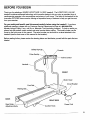
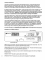
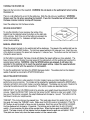
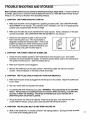
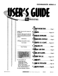
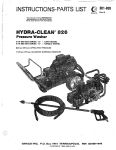
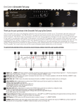
£SP
• 0-10.0 MPH • 1.;_NP DC MOTOR • WIDE TRAKFRAME
• SOF[ STRIDEADJU$ TABLE SUSPENSIONDECK
• ELECTRONICPOWER INCLINE • MADEIN THE U,S.A.
Model No. 831.297051
Serial No.
V-erial Number
Decal
OWNER'S MANUAL
CA UTION:
Carefully read all safety precautions and instructions in this manual
before using this equipment. Save this manual for future reference.
iiii i
iii ,11
FULL 90 DAY WARRANTY
ON PARTS
For 90 days from the date of purchase, when proper assembly and maintenance
procedures
detailed in the Owner's Manual are followed, SEARS wil!, free of charge, repair or replace and
install a replacement
ner.
This warranty
part for any defective
part, when this treadmill
does not apply when this treadmill
SERVICE IS AVAILABLE
CENTER/DEPARTMENT
is used for commercial
SIMPLY BY CONTACTING
IN THE UNITED STATES.
This warranty gives you specific
from state to state.
SEARS,
is used in a normal
YOUR NEAREST
man-
or rental purposes.
SEARS
SERVICE
legal rights, and you may also have other rights which vary
ROEBUCK
3333 BEVERLY
ROAD,
AND CO., DEPT. 817WA,
HOFFMAN
ESTATES,
IL 60179
ESP
• EXTENDED
Ak0. I0,0 MPil • I..#HP OC MOTOR •WIDE TRAK FRAME
• SOFTSTRIDEAOJUSTABLE
8 TRIOEPROFILE
SUSPENSION DECK
• ELECTRONICPOWER/NCLINE • MADEIN TIIE U,S.4.
TABLE OF CONTENTS
Important Safety Precautions ......................
Before "You Begin ...............................
Assembly
.....................................
Operation and Adjustment
........................
Trouble-Shooting
and Storage .....................
Conditioning
Guidelines
..........................
Part List ......................................
4
5
6
7
11
13
14
Exploded Drawing ..............................
Ordering Replacement
Parts ......................
15
Back Cover
WARNING:
Before
beginning
this or any exercise
program,
consult
your physician.
This
is especially important for persons over the age of 35 or persons with pre-existing
health problems. Read all instructions before using. SEARS assumes no responsibility
for personal Injury
or property damage sustained by or through the use of this product.
IMPORTANT SAFETY PRECAUTIONS
WARNING:
following
1
.
To reduce
important
the risk of burns,
safety precautions
fire, electric
and Information
shock or injury to persons,
before operating
read the
the treadmill.
Position the treadmill on a level surface, with at least 8 feet of clearance behind the treadmill. Do not place the treadmill near water, outdoors or on a surface that blocks any air
opening.
Do not operate where aerosol products are used or where oxygen is being administered.
Plug the power cord directly into a grounded circuit carrying 12 or more amps. No other
appliance should be on the same circuit. (See OPERATION
AND ADJUSTMENT
in this manual for proper grounding
instructions.)
Keep the power cord away from heated surfaces.
If
an extension cord is required, use only a 14-gauge general-purpose
cord of approximately
five feet in length
with a three-wire
conductor.
3. Never move the walking belt while the power is turned off. Do not operate the treadmill
the power cord or plug is damaged, or if the treadmill is not working properly. (See
BEFORE YOU BEGIN in this manual if the treadmill is not working properly.)
.
if
Wear appropriate
exercise clothing when using the treadmill; do not wear loose clothing
that could become caught in the treadmill.
Always
wear running shoes; never use the
treadmill with bare feet, wearing only stockings or in sandals.
Athletic support clothes are
recommended
for both men and women.
5. The pulse earclip is not a medical device. Various factors, including the user's movement
while exercising,
may affect the accuracy of heart rate readings.
The earclip is intended
only as an exercise aid in determining
heart rate trends in general.
6. Never start the treadmill while you are standing
handrail when exercising on the treadmill.
on the walking
7. Never allow more than one person on the treadmill
used by persons
weighing
at a time.
belt.
Always
The treadmill
hold the
should
not be
more than 250 pounds.
8. Keep small children away from the treadmill at all times. Never leave the treadmill
unattended
while it is running.
Always turn the power off when the treadmill is not in use.
9. Never drop or insert any object into any opening.
10.
To prevent
overheating,
11. The treadmill
speed.
12.
is capable
Use the treadmill
13. Always
do not operate
the treadmill
of high speeds.
only as described
Adjust
the speed
for longer than 1 hour.
slowly to avoid sudden jumps
in
in this manual.
unplug the power cord before
procedures
described in this manual.
performing the maintenance
and adjustment
Never remove the motor hood unless Instructed
do so by an authorized service representative.
manual should be performed
by an authorized
4
continuously
SAVE THESE INSTRUCTIONS
Servicing other than the procedures
service representative
only.
to
in this
BEFORE YOU BEGIN
Thank you for selecting a SEARS _'LIFESTYLER
10.0 ESP treadmill.
The LIFESTYLER
10.0 ESP
treadmill combines advanced technology with innovative design to let you enjoy an excellent form of
cardiovascular
exercise in the convenience
and privacy of your home. The heart of the treadmill is the
innovative OPTIONS*
from your exercise.
base console,
offering an impressive
array of features
to help you get the most
For your safety and benefit, read this manual carefully before using the treadmill.
If you have
additional questions, please call our Customer Service Department toll-free at 1-800-999-3756,
Monday through Friday, 6 a.m. until 6 p.m. Mountain "l'ime (excluding holidays). To help us assist you,
please note the product model number and serial number before calling. The model number can be
found on the front cover of this manual. The serial number can be found on a decal attached to the
treadmill (see the front cover of this manual for the location).
Before reading further, please review the drawing
labeled.
below and familiarize yourself
with the parts that are
Safety Key/Clip
Pulse Earcli
:line Control
FRONT
Motor Hood
Circuit Breaker
Foot
Walking
BACK
RIGHT
Rear Roller
Adjustment
SIDE
Power Cord
Bolts
Cushion
Knob
_&
ASSEMBLY
Set the treadmill in a cleared area and remove all packing materials.
Included
before disposing
of the packing
Be sure that all parts are
materials.
Align the lower end of the Right Handrail (20) with the
holes in the side of the treadmill Frame (47). Attach the
Handrail with two Short Handrail Bolts (35) and Handrail
1,
Washers (36). Do not fully tighten the Bolts. Attach the
Left Handrail (not shown) in the same manner.
20
47
36
35
Place the Console (8) on the upper end of the Left and
Right Handrails (1,20) as shown. Attach the Console
with two Long Handrail Bolts (2). Do not fully tighten the
Bolts.
2,
'
.
Plug the Handrail Wire Harness (62), located in the
Right Handrail (20), into the connector on the underside
of the Console (8). The small latch on the Harness
should snap onto the connector. If the Harness does
not fit easily, turn it; do not force the Harness into the
connector.
1
8
62
.
Plug the lower end of the Handrail
Wire Harness
(62)
into the connector on the right side of the Belly Pan (38).
The small latch on the Harness should snap onto the
connector.
If the Harness does not fit easily, turn it; do
not force the Harness into the connector.
5.
Firmly tighten the Bolts on the lower and upper ends of
both Handrails
38
(not shown).
62
Make sure that all parts are tightened securely before using
the treadmill.
.6
OPERATION AND ADJUSTMENT
GROUNDING
INSTRUCTIONS
This product must be grounded.
If it should malfunction or break down, grounding provides a path
of least resistance for electric current to reduce the risk of electric shock. This product is equipped with
a cord having an equipment-grounding conductor and a grounding plug. The plug must be plugged
into an appropriate outlet that is properly
codes and ordinances.
DANG ER: Improper
connection
installed
and grounded
of the equipment-grounding
in accordance
with all local
conductor can result in a risk of
electric shock. Check with a qualified electrician or serviceman if you are in doubt as to whether the
product is properly grounded. Do not modify the plug provided with the product--if it will not fit the outlet, have a proper outlet installed by a qualified electrician.
This product is for use on a nominal 120-volt circuit, and has a grounding plug that looks like the plug
illustrated in Drawing 1. A temporary adapter that looks like the adapter illustrated in Drawing 2 may
be used to connect this plug to a 2-pole receptacle as shown in Drawing 2 if a properly grounded outlet
is not available. The temporary adapter should be used only until a properly grounded outlet (Drawing
1) can be installed by a qualified electrician. The green colored rigid ear, lug, or the like extending from
the adapter must be connected to a permanent ground such as a properly grounded outlet box cover.
Whenever the adapter is used it must be held in place by a metal screw. Some 2-pole receptacle
outlet box covers are not grounded.
Contact a qualified electrician to determine if the outlet
box cover is grounded before using an adapter.
Grounded
Outlet Box
Grounding
2
Z)utlet Box
Plug
Pin
Grounding
Grounding
Pin
Lug
Grounded Outlet
MAINTENANCE-FREE
WALKING
Plug
Metal Screw
PLATFORM
This treadmill features a walking platform coated with a specially-designed
hydrocarbon
slip agent. Do
not apply silicone spray or any other substances
to the walking platform or the walking belt.
Such substances will deteriorate the surface of the walking platform and cause excessive wear. Walk
on the treadmill for 10 minutes to break in the walking platform. During this break-in period, it is normal
for the walking belt to slow.
CUSHION
LEVEL ADJUSTMENT
Cushion
The cushion level of the treadmill can be adjusted using the
cushion knob located on the right side of the treadmill.
Turning the knob counterclockwise
will result in a softer
cushion as you exercise; turning the knob clockwise will
result in a more firm cushion.
Knob\
t
]
CONSOLE
OPERATION
The heart of the treadmill
is the innovat ve OPTIONS
base console.
The OPTIONS
base console
features a safety key-operated
power switch, a large, easy-to-read
LED display, convenient pushbutton speed controls and a multiple-mode
exercise monitor. And the OPTIONS base console is
modular_p
to three different
modules
(not included)
can be added to give you even more options!
By adding the state-of-the-art
VIDEO TRACK TM module, the base console can be connected to your TV
and VCR for exciting motivational workouts.
A videocassette
will take you on a tour of some of the
most breathtaking
scenery
in America,
while the module controls
the treadmill
automatically
to simulate
the terrain you are viewing. WARNING_
Keep videocassettes
at least ,two feet away from treadmill
motor hoods. Treadmill motors contain magnets which can damage videocassettes.
The powerful TRACK FIVE TM module offers five preset workout programs, each designed to give you a
different type of workout.
Simply select one of the programs, set the length of time that you plan to
exercise and choose a workout intensity level. The TRACK FIVE module will control the treadmill
automatically
as it guides
you through
an invigorating
cardiovascular
workout.
The versatile PERSONAL TRAINER PLUS TM module lets you create an endless variety of custom
workout programs.
Up to four programs can be stored in memory at the same time, and recalled for
future workouts.
The module is also compatible with PERSONAL TRAINER programs.
Just connect
the module to your telephone, and give PERSONAL TRAINER a call. Your PERSONAL TRAINER will
provide you with a workout program designed to help you achieve the specific results you want, and
load the program into the module using the special telephone hook-up provided.
For more information,
DIAGRAM
see ORDERING
REPLACEMENT
PARTS
on the back cover of this manual.
OF THE BASE CONSOLE
Mode Indicators
\
I q.SS
l I OPT ONS ...........................
'_7' _
im P.Jt_
m$ol_
z_.
_
V-1 r--1V-1 r
- -/ :: EIATt
I
°T
t_E/y
_rf
Incline Indicator j
Pulse Earclip Jack
MANUAL
SELECT
button is needed
START/PAUSE
the walking
BUTTON---This
only when modules
BUTTON--This
8
SPEED
BUTTON---This
to the manual
mode.
Note:
This
are used with the base console.
button stops the walking belt.
belt when modules
SET BUTTONS--These
the base console.
MODE
button switches the base console
Note:
This button both starts and stops
are used with the base console.
buttons are used to set time and distance goals, and to enter your weight into
button is used to select
BUTTONS---These
monitor modes.
buttons are used to control the speed of the walking belt.
TURNINGTHE POWERON
Stepontothe foot
rails of the treadmill.
WARNING:
Do not stand on the walking
belt when turning
the power on.
There is a clip attached by a cord to the safety key. Slide the clip onto your waistband. WARNING:
Always wear the clip when operating the treadmill.
If you fall, the safety key will be pulled from
the base console, instantly turning off the power.
Insert the safety key into the base console.
INCLINE
ADJUSTMENT
To vary the intensity of your exercise, the incline of the
treadmill can be adjusted using the buttons on the right side
of the console. Each time one of the buttons is pressed, the
incline will change by 1%. Indicators will light to show the
current incline setting.
MANUAL
SPEED
MODE
When the power is turned on, the walking belt will be stationary. The speed of the walking belt can be
controlled with the SPEED buttons. The minimum speed setting is 0.5 miles per hour. Each time one
of the buttons is pressed, the speed will change by 0.1 mile per hour. The buttons can be held down to
change the speed quickly.
As the buttons are pressed, the base console will display the speed setting you have selected.
The
base console will then display the actual speed of the walking belt, until the walking belt reaches the
selected speed setting. WARNING:
After the SPEED buttons are pressed, it will take a few
seconds for the walking belt to reach the selected speed setting. Adjust the speed gradually
until you are familiar with the operation of the treadmill.
To stop the walking belt, hold down the SPEED decrease
quickly, if desired, by pressing the START/PAUSE button.
SELECTING
MONITOR
button.
The walking belt can be stopped
MODES
The base console offers a wide selection of monitor modes to give you instant feedback on your
performance as you exercise.
The modes can be selected by repeatedly pressing the MODE button.
Indicators will light to show which mode is currently displayed.
The display can be reset, if desired, by
removing the safety key and then reinserting it. The monitor modes are described below.
WEIGHT SET: For the CALORIES mode to be accurate, your weight should be entered into the base
console. Select the WEIGHT SET mode and then press the SET buttons to enter your weight. Each
time one of the buttons is pressed, the weight displayed will change by 1 pound. The buttons can be
held down to enter your weight quickly.
TIME/SET:
This mode displays
the elapsed
time.
This mode also allows time goals to be set. To set a
time goal, first select the TIME/SET mode. (Make sure the SCAN mode is not selected.)
Press the
SET buttons to set the length of time you plan to exercise.
Each time one of the buttons is pressed,
the time displayed will change by 10 seconds. The buttons can be held down to set a time goal
quickly. As you exercise, the time will be counted down. When the time goal is completed, a tone will
sound. The base console will then display the time elapsed since the goal was completed.
Note:
Time goals can be set only when the base console
is in the manual
mode.
DISTANCE/SET:This modedisplaysthe distanceyou havetraveled. This modealsoallowsdistance
goals to be set. Toset a distancegoaT,first selectthe DISTANCE/SET
mode. (Makesurethe SCAN
modeis not selected.) Pressthe SET buttonsto setthe distanceyouplan to travel. Eachtime oneof
the buttonsis pressed,the distancedisplayedwill changeby 0.2 miles. The buttonscan be held down
to set a distancegoal quickly. As you exercise,the distancewill be counteddown. Whenthe distance
goal is completed,a tone will sound. The console will then display the distance you have traveled
since the goal was completed.
manual mode.
SPEED:
buttons
This mode displays
is pressed,
Note:
Distance
goals can be set only when the base console
the speed of the walking
this mode will be displayed
belt.
automatically
Note:
is in the
Each time one of the SPEED
for approximately
CALORIES:
This mode displays the total number of Calories you have burned.
select the WEIGHT SET mode and enter your weight into the base console.
5 seconds.
For accuracy,
first
PULSE: This mode displays your heart rate. Plug the pulse earclip into the jack on the base console,
and attach the earclip to your left ear lobe. Slide the clothes clip onto your collar to prevent excessive
movement of the earclip wire. After a few seconds, your heart rate will be displayed.
Note: If your
heart rate is not displayed, rub your ear lobe lightly and reposition the earclip.
SCAN: This mode automatically
displays all modes except WEIGHT SET, for approximately
3
seconds each, in a repeating cycle. Note: The PULSE mode will be displayed only if the pulse earclip
is worn.
TURNING
OFF THE
POWER
Stand on the foot rails of the treadmill.
Always remove
10
Remove
the safety key from the base console.
the safety key from the base console
when you finish exercising.
WARNING:
TROUBLE-SHOOTING AND STORAGE
Most treadmill problems can be solved by following the simple steps below.
If further assistance
is needed, please call our Customer Service Department toll-free at 1-800-999-3756,
Monday through
Friday, 6 a.m. until 6 p.m. Mountain Time (excluding holidays).
1. SYMPTOM:
THE POWER
DOES NOT TURN
ON
a. Make sure the power cord is plugged into a properly grounded outlet. (See OPERATION
AND
ADJUSTMENT
in this manual.) if an extension cord is necessary, use only a 14-gauge generalpurpose cord of approximately
five feet in length.
b. Make sure the safety key is fully inserted into the base console.
console should light. (See OPERATION
C.
AND ADJUSTMENT
Various indicators on the base
in this manual.)
Check the circuit breaker located on the front of the
frame near the power cord. The circuit breaker is
designed to protect the electrical system. If the circuit
breaker has tripped, the switch will protrude as shown.
To reset the circuit breaker, allow the treadmill to cool
for five minutes, and push the switch back in.
2. SYMPTOM:
THE POWER TURNS
OFF DURING
Reset
Tripped
USE
a. Check the circuit breaker located on the treadmill frame near the power cord. If the switch
protrudes, the circuit breaker has tripped. To reset the circuit breaker, wait for five minutes and
then press the switch back in. (See the drawing above.)
b. Make sure the power cord is plugged in.
c. Remove the safety key from the base console. Reinsert the safety key fully into the base
console, Various indicators on the base console should light.
3. SYMPTOM:
THE PULSE
EARCLIP
DOES NOT FUNCTION
PROPERLY
a. Make sure the pulse earclip is plugged fully into the jack on the console.
to your collar.
b. Rub your left ear lobe and reposition
C.
Attach the clothes clip
the earclip.
Try standing still while measuring your pulse. WARNING:
The pulse earclip Is not a medical
device. Various factors, including the user's movement while exercising,
may affect the
accuracy of heart rate readings.
The earclip is Intended only as an exercise aid in
determining
heart rate trends in general.
d. The pulse earclip may need to be cleaned.
circles inside the earclip,
4. SYMPTOM:
THE WALKING
Press the earclip open, and wipe the two clear
using a cotton swab saturated with denatured
BELT SLOWS
WHEN
WALKED
ON
a. Walk on the treadmill for 10 minutes to break in the walking platform.
it is normal for the walking belt to slow.
alcohol.
During this break-in period,
11
b. If an extension
feet in length.
C.
cord is needed, use only a 14-gauge
general-purpose
cord of approximately
five
If the walking belt is overtightened, treadmill performance
may be reduced and the walking belt permanently
damaged.
TURN THE POWER OFF. Turn beth rear
roller adjustment bolts counterclockwise,
1/4 of a turn.
Repeat until the tension of the walking belt is correct.
When the tension is correct, you should be able to lift
each side of the walking belt 3-4 inches off the walking
platform. The center of the walking belt should remain
just at the surface of the walking platform.
Be careful to
keep the walking
5. SYMPTOM:
belt centered
on the walking
platform.
THE WALKING BELT IS OFF-CENTER OR SLIPS WHEN WALKED ON
a. If the walking belt has shifted to the left, first TURN THE
POWER OFF. Turn the left rear roller adjustment bolt
clockwise, and the right bolt counterclockwise,
1/4 of a
turn each. Repeat as necessary until the walking belt is
centered.
b. If the walking belt has shifted to the right, first TURN
THE POWER OFF. Turn the left rear roller adjustment
bolt counterclockwise,
and the right bolt clockwise, 1/4 of
a turn each. Repeat as necessary until the walking belt
is centered.
Co
If the walking belt slips when walked on, first TURN THE
POWER OFF. Turn both rear roller adjustment bolts
clockwise, 1/4 of a turn. Repeat as necessary until the
tension of the walking belt is correct. When the tension is
correct, you should be able to lift each side of the Walking
belt 3-4 inches off the walking platform.
The center of the
walking belt should remain just at the surface of the walking platform.
Be careful to keep the walking
on the walking platform.
belt centered
STORAGE
Unplug the power cord when the treadmill is not in use. Remove the bolts and washers from the lower
end of the handrails.
Keep the bolts and washers in a secure location. Carefully lay the handrails and
console on the treadmill.
12
CONDITIONING
GUIDELINES
The following guidelines will help you to plan your exercise program. Remember that proper nutrition
and adequate rest are essential for successful results. WARNING;
Before beginning this or any
exercise program, consult your physician.
This is especially Important for individuals
over the
age of 35 or individuals
EXERCISE
with pre-existing
health problems.
INTENSITY
To maximize the benefits of exercising, it is important to exercise with the proper intensity. The proper
intensity can be found by using your heart rate as a guide. For effective aerobic exercise, your heart
rate should be maintained at a level between 70% and 85% of your maximum heart rate as you
exercise. This is known as your training zone. You can find your training zone in the table below.
Training zones are listed for both unconditioned and conditioned persons according to age.
AGE
UNCONDITIONED
TRAINING ZONE
(BEATS/MIN)
CONDITIONED
TRAINING ZONE
(BEATS/MIN)
AGE
UNCONDITIONED
TRAINING
ZONE
(BEATS/MIN)
CONDITIONED
TRAINING
ZONE
(BEATS/MIN)
20
138-167
133-162
55
127-155
122-149
25
136-166
132-160
60
126-153
121-147
r
,
,
,,
3O
135-164
130-158
65
125-151
119-145
35
134-162
129-156
70
123-150
118-144
4O
132-161
127-155
75
122-147
117-142
45
131-159
125-153
80
120-146
115-140
50
129,.156
124-150
85
118-144
114-139
During the first few months of your exercise program, keep your heart rate near the low end of your
training zone as you exercise. After a few months of regular exercise, your heart rate can be increased
gradually until it is near the middle of your training zone as you exercise. You can measure your heart
rate using the pulse mode of the console. Exercise for at least four minutes, and then measure your
heart rate immediately. If your heart rate is too high, decrease the intensity of your exercise. If your
heart rate is too low, increase the intensity of your exercise. WARNING:
The pulse earcllp is not a
medical device. Various factors, including your movement during exercise, may affect the
accuracy of heart rate readings.
heart rate trends in general.
WORKOUT
The earclip
is intended
only as an exercise
aid in determining
GUIDELINES
Each workout should consist of three basic pads: a warm-up, 20 to 30 minutes of training zone exercise, and a cool-down. Warming up prepares the body for exercise by increasing circulation, delivering more oxygen to the muscles and raising the body temperature. Begin each workout with 5 to 10
minutes of stretching and light exercise to warm up. Then, increase the intensity of your exercise to
raise your heart rate to your training zone for 20 to 30 minutes. Breathe regularly and deeply as you
exercise---never
hold your breath. Finish each workout with 5 to 10 minutes of stretching to cool down.
This will increase the flexibility
exercise problems.
of your muscles as well as help to decrease
To maintain or improve your condition, complete three workouts
rest between workouts.
After a few months of regular exercise,
each week, if desired.
The key to success
is CONSISTENCY.
soreness and other post-
each week, with at least one day of
you may complete up to five workouts
13
PART LIST--Model
KeyReorder
No.
No.
_t4
Qty.
No. 831.297051
.
Description
Rev.
8/92
Key
No.
Reorder
No.
Qty.
Left Handrail
Long Handrail Bolt
Safety Key/Clip
Clothes Clip
Pulse Earclip
Small Screw
Console Plate
Console
41
44
45
46
47
48
49
50
104514
109088
105395
109348
NSP
105477
109242
101263
1
1
1
2
1
8
1
1
Tension Spring
Walking Platform
Walking Belt
Foot Rail
Frame
Motor Mount Nut
Motor Mount Plate
Motor Pivot Bolt
Description
1
2
3
4
5
6
7
8
109244
013464
106337
054013
101508
108080
109274
109356
1
2
1
1
1
33
1
1
9
10
11
12
13
109370
102959
102955
109371
012152
1
2
2
1
2
Incline Optic Disk
Switch Bolt
Optic Switch
Incline Switch Bracket
Switch Nut
51
52
53
54
55
108473
108474
108965
106114
109268
4
1
1
1
1
Motor Isolator
Ground Strap
Motor
Pulley/Flywheel/Fan
Cushion Knob
14
15
16
17
18
109270
012108
013564
105329
108580
1
7
4
2
1
Incline Motor
Locknut
Leg Bolt/Motor
Wheel Bolt
Controller
56
57
58
59
60
103303
014066
109259
109267
109257
4
4
2
1
2
Cushion Spring Knob
Lock Washer
Spring Shim
Adjustment Knob
Cushion Cover
19
20
21
22
23
031238
109246
109465
014157
019084
2
1
4
2
1
Choke
Right Handrail
Hood Anchor
Ground Washer
Grommet
61
62
63
64
65
109620
109252
108470
105444
045010
2
1
1
2
1
Cushion Spring/Foot
Handrail Wire Harness
Right Endcap
Rear Roller Adj. Bolt
Allen Wrench
24
25
013229
031103
1
1
Power Cord
Circuit Breaker
66
67
016028
105894
1
1
Wrench Clip
Rear Roller
26
27
28
29
30
31
32
33
34
35
109269
104623
106615
014127
052014
108062
015071
109105
101577
013564
2
10
1
3
2
1
4
1
2
4
68
69
70
71
72
7374
75
76
77
108469
100691
109278
109357
108778
109358
106939
109103
109372
109251
1
6
8
1
2
1
1
1
1
2
Left Endcap
Platform Screw
Foot Rail Washer
Motor Hood
Speed Disk Retainer
Speed Optic Disc
Belt
Speed Switch Bracket
Incline Bracket Screw
Short Wire Harness
36
37
'38
39
40
42
43
014087
109265
108603
103855
014041
012082
109360
4
2
1
1
1
1
1
78
79
80
81
82
#
101577
106404
109438
109723
109518
110432
2
4
1
1
1
1
Endcap Screw
Hood Screw
Power Supply Plate
Rod Washer
Rod Endcap
Owner's Manual
Bolt
Frame Endcap
Belly Pan Pin
Front Roller Adj. Bolt
, Roller Adjustment Washer
Front Wheel
Power Supply Board
Plastic Stand-Off
Incline Leg
Deck Screw
Short Handrail Bolt
Handrail Washer
Belt Guide
Belly Pan
J-Bolt
J-Bolt Washer
J-Bolt Nut
Front Roller Pulley
Note: "#" indicates a non-illustrated part. Specifications
are subject to change
back cover of this manual for information about ordering replacement parts.
without
notice.
See the
EXPLODED DRAWINGmModel
NO. 831.297051
Re,,e/92
12
11 \ 13
10_76
15
82
71
35
25
126
44
42
15
29
'
30 :
67
60
© 1992 Sears, Roebuck
and Co.
15
ORDERING REPLACEMENT
PARTS
Each TREADMILL
has its own MODEL NUMBER.
Always
requesting service or repair parts for your TREADMILL.
All parts listed may be ordered
SEARS RETAIL STORES.
through
SEARS,
ROEBUCK
mention
the MODEL
AND CO. SERVICE
NUMBER
CENTERS
If parts you need are not stocked locally, your order will be electronically
PARTS DISTRIBUTION
CENTER for expedited handling.
transmitted
WHEN ORDERING
INFORMATION:
1. The MODEL
REPAIR
NUMBER
of the product
2. The NAME of the product
3. The REORDER
NUMBER
4. The DESCRIPTION
Your SEARS
PARTS, ALWAYS
and most
to a SEARS
(831.297051).
(SEARS * LIFESTYLER
of the part(s),
of the part(s),
merchandise
GIVE THE FOLLOWING
when
10.0 ESP treadmill).
from page 14 of this manual.
from page 14 of this manual.
has added value when you consider
that SEARS
has service
units nation-
wide staffed with SEARS trained technicians
specifically trained on SEARS products, having the parts,
tools and equipment to ensure that we meet our pledge to you: "We service what we sell.
SOLD BY SEARS,
ROEBUCK
Part No. 110432 8/92 Printed
AND CO., HOFFMAN
in USA
ESTATES,
IL 60179