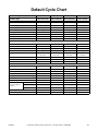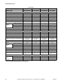
1
Programming
Washer-Extractor
Refer to Page 4 for Model Numbers
CHM495R
Keep These Instructions for Future Reference.
(If this machine changes ownership, this manual must accompany machine.)
www.comlaundry.com
Part No. F8208501R4
April 2012
WARNING
Failure to install, maintain, and/or operate
this machine according to the
manufacturer's instructions may result in
conditions which can produce bodily injury
and/or property damage.
W030
NOTE: The WARNING and IMPORTANT
instructions appearing in this manual are not meant
to cover all possible conditions and situations that
may occur. It must be understood that common
sense, caution, and carefulness are factors which
cannot be built into these washer-extractors. These
factors MUST BE supplied by the person(s)
installing, maintaining, or operating the washerextractor.
Always contact the distributor, service agent, or
the manufacturer about any problems or conditions you do not understand.
F8208501
© Copyright, Alliance Laundry Systems LLC – DO NOT COPY or TRANSMIT
1
Table of
Contents
Model Identification ...........................................................................
Preliminary Information....................................................................
About the Control .................................................................................
Glossary of Terms.................................................................................
Power Failure Recovery .......................................................................
Control Identification.........................................................................
Display Identification .........................................................................
Light Emitting Diodes (LEDs) .............................................................
Washer-Extractor Operation ............................................................
Start Up.................................................................................................
Ready Mode..........................................................................................
Partial Vend Mode (Vended Models Only)..........................................
Signals...................................................................................................
Start Mode ............................................................................................
Door Locking Mode .............................................................................
Run Mode .............................................................................................
Changing Cycles...................................................................................
Door Unlock Mode ...............................................................................
End of Cycle Mode...............................................................................
Special Features ..................................................................................
Programming Control ...........................................................................
Collecting Audit Information ...............................................................
Production Test Cycle...........................................................................
Rapid Advance Feature.........................................................................
Coin Drop .............................................................................................
OPL Mode ............................................................................................
Power Save Mode (OPL Models Only)................................................
Opening the Top Cover ......................................................................
Programming the DIP Switch............................................................
Entering the Manual Mode................................................................
How to Enter the Manual Mode ...........................................................
Programming Control ........................................................................
What Can Be Programmed? .................................................................
Programmable Options Available.........................................................
1. Vend Price “AtS” .........................................................................
2. Coin #1 Value “dEn1” .................................................................
3. Coin #2 Value “dEn2” .................................................................
4. Error Codes “ErrS” ......................................................................
5. Coin Audio Beep “CoAU”...........................................................
6. Card Display Option “CArd”.......................................................
7. Total # of Machine Cycles “CyC” ...............................................
8. Total # of Rapid Advance Cycles “rCyC” ...................................
9. Prewash Fill Level “PLEU”.........................................................
10. Wash Fill Level “ALEU”.............................................................
11. Rinse #1, #2 and #3 Fill Level “rLEU” .......................................
12. Prewash Enable “PrEn” ...............................................................
13. Prewash Time “PdUr”..................................................................
14. Wash Time “AdUr” .....................................................................
15. Intermediate Rinse Spins Enable “SPEn”....................................
16. Rinse #2 Enable “r2En” ...............................................................
17. Hot Cycle Temperature “FH” (Heat Enabled Only)....................
18. Warm Cycle Temperature “FHC” (Heat Enabled Only) .............
4
5
5
5
5
6
7
7
8
8
8
8
8
8
8
8
8
8
8
9
9
9
9
9
9
9
9
10
11
12
12
13
13
13
18
18
19
19
20
20
21
21
22
22
23
23
24
24
25
25
26
26
© Copyright 2012, Alliance Laundry Systems LLC
All rights reserved. No part of the contents of this book may be reproduced or transmitted in any form or by any
means without the expressed written consent of the publisher.
2
© Copyright, Alliance Laundry Systems LLC – DO NOT COPY or TRANSMIT
F8208501
19.
20.
21.
22.
23.
24.
25.
Cycle Pause Enable “CyCP” (Gravity Drain Models Only)........
Leak Detection During Cycle Enable “LdEn”.............................
Slow Drain Detection During Cycle Enable “SdEn”...................
Slow Drain Detection Adjustment “SdAd” .................................
Number of Balance Retries “bALr” (Design 2 Models Only).....
Leak Detection Test “Ldt” ...........................................................
Balance Weight Test “bALt”
(F-speed Design 1 Models Only).................................................
25. DC Bus Display Test “dCbt” (Design 2 Models Only) ...............
26. DIP Switch Test “dIPt” ................................................................
27. Rapid Advance “rAPd”................................................................
28. Exit Manual Mode “End” ............................................................
Production Test Cycle ........................................................................
Error Codes.........................................................................................
Power Fail Recovery...........................................................................
Default Cycle Chart............................................................................
F8208501
© Copyright, Alliance Laundry Systems LLC – DO NOT COPY or TRANSMIT
27
27
28
28
29
29
30
30
31
31
32
33
37
40
41
3
Model Identification
Information in this manual is applicable to these
washer-extractor models:
4
HCD020GD2
HCU020GC2
SCD030GD2
SCN080GCF
SCU080GLF
HCL020GD2
HCU020GD2
SCD040GD2
SCN080GDF
SCU080GNF
HCL020GN2
HCU020GE2
SCD060GD2
SCN080GEF
SCU080GXF
HCL030GN2
HCU020GL2
SCL020GC2
SCN080GNF
SCU080GYF
HCL040GN2
HCU020GN2
SCL020GN2
SCN080GXF
UCL020GN2
HCL060GN2
HCU020GX2
SCL030GC2
SCN080GYF
UCL020GNF
HCL060GCF
HCU020GY2
SCL030GN2
SCU020GC2
UCL030GN2
HCN020GC2
HCU030GC2
SCL040GC2
SCU020GD2
UCL030GNF
HCN020GD2
HCU030GD2
SCL040GN2
SCU020GE2
UCL040GN2
HCN020GE2
HCU030GE2
SCL060GC2
SCU020GL2
UCL040GNF
HCN020GN2
HCU030GL2
SCL060GN2
SCU020GN2
UCL060GN2
HCN020GX2
HCU030GN2
SCL080GNF
SCU020GX2
UCL060GNF
HCN020GY2
HCU030GX2
SCN020GC2
SCU020GY2
UCL080GNF
HCN030GC2
HCU030GY2
SCN020GD2
SCU030GC2
UCN020GN2
HCN030GD2
HCU040GC2
SCN020GE2
SCU030GD2
UCN020GNF
HCN030GE2
HCU040GD2
SCN020GN2
SCU030GE2
UCN030GN2
HCN030GN2
HCU040GE2
SCN020GX2
SCU030GL2
UCN030GNF
HCN030GX2
HCU040GL2
SCN020GY2
SCU030GN2
UCN040GN2
HCN030GY2
HCU040GN2
SCN030GC2
SCU030GX2
UCN040GNF
HCN040GC2
HCU040GX2
SCN030GD2
SCU030GY2
UCN060GN2
HCN040GD2
HCU040GY2
SCN030GE2
SCU040GC2
UCN060GNF
HCN040GE2
HCU060GC2
SCN030GN2
SCU040GD2
UCN080GNF
HCN040GN2
HCU060GD2
SCN030GX2
SCU040GE2
UCU020GN2
HCN040GX2
HCU060GE2
SCN030GY2
SCU040GL2
UCU020GNF
HCN040GY2
HCU060GL2
SCN040GC2
SCU040GN2
UCU030GN2
HCN060GC2
HCU060GN2
SCN040GD2
SCU040GX2
UCU030GNF
HCN060GD2
HCU060GX2
SCN040GE2
SCU040GY2
UCU040GN2
HCN060GE2
HCU060GY2
SCN040GN2
SCU060GC2
UCU040GNF
HCN060GN2
HCU080GCF
SCN040GX2
SCU060GD2
UCU060GN2
HCN060GX2
HCU080GDF
SCN040GY2
SCU060GE2
UCU060GNF
HCN060GY2
HCU080GEF
SCN060GC2
SCU060GL2
UCU080GNF
HCN080GCF
HCU080GLF
SCN060GD2
SCU060GN2
UCZ020GN2
HCN080GDF
HCU080GNF
SCN060GE2
SCU060GX2
UCZ030GN2
HCN080GEF
HCU080GXF
SCN060GN2
SCU060GY2
VCU030GN2
HCN080GNF
HCU080GYF
SCN060GNF
SCU080GCF
VCU040GN2
HCN080GXF
HCZ020GN2
SCN060GX2
SCU080GDF
VCU060GN2
HCN080GYF
HCZ030GN2
SCN060GY2
SCU080GEF
VCU080GNF
© Copyright, Alliance Laundry Systems LLC – DO NOT COPY or TRANSMIT
F8208501
Preliminary Information
About the Control
Glossary of Terms
This control is a programmable computer that lets the
owner control most machine features by setting dip
switches and pressing buttons on the back of the
control.
The following are a few terms and abbreviations to
learn. These are referred to throughout the instructions.
The control allows the owner to program custom
cycles, set vend prices, retrieve audit information, run
tests and other programmable features. Refer to
Programming Control for a list of features.
Display – This term refers to the window area of the
control that displays words and values.
LED (Light Emitting Diode) – This term refers to the
lights next to the status words of the control.
Power Failure Recovery
IMPORTANT: In the event of a power failure, the
control will not have to be reprogrammed. It is
designed with a memory system that will remember
how it was programmed until the electrical power
is restored.
If a cycle is in progress and the power fails, the cycle
status is saved in memory. When the power recovers,
the machine will resume into the previously active
cycle if the power outage is less than five (5) seconds
and the door is closed and locked.
IMPORTANT: It is extremely important that the
machine has a good ground connection and that all
mechanical and electrical connections to the control
are made before applying power to or operating the
machine.
If the length of the power failure is greater than five
(5) seconds, the control will enter Start Mode and
require pressing the start switch. If the power failure is
greater than five (5) seconds and OPL Mode is
enabled, the cycle can not be resumed.
F8208501
© Copyright, Alliance Laundry Systems LLC – DO NOT COPY or TRANSMIT
5
Control Identification
1
3
2
4
5
CHM495R
1
2
3
4
5
Display
Four 7-Segment Digits
CYCLE/TEMPERATURE Selector Switch
START Switch
LED Status Lights
Figure 1
6
© Copyright, Alliance Laundry Systems LLC – DO NOT COPY or TRANSMIT
F8208501
Display Identification
Light Emitting Diodes (LEDs)
(Refer to Figure 1)
Light Emitting Diodes (LEDs) are used to indicate the
cycle status and door lock information. See below for
information on each LED.
SPIN LED
Spin LED is lit during the Final Extract portion of the
cycle.
DOOR LED
WASH LED
Door LED is lit whenever the door is locked. The door
can’t be opened when this LED is lit.
Wash LED is lit during the wash and prewash portion
of the cycle.
BLEACH LED
RINSE LED
Bleach LED flashes one (1) second on and one
(1) second off when the bleach dispenser is flushing.
Rinse LED is lit during the rinse portion of the cycle.
Four 7-Segment Digits
The 7-Segment Digits are used to display the time
remaining in a cycle, vend price, error messages and
descriptive codes. During manual programming of the
control, these digits will display descriptive codes and
values (as described in Entering the Manual Mode).
F8208501
© Copyright, Alliance Laundry Systems LLC – DO NOT COPY or TRANSMIT
7
Washer-Extractor Operation
Start Up
Run Mode
When power is applied to the machine, the control will
display its software version as “S xx” (“xx” is the
version number) for one (1) second. If the control was
not powered down during a running cycle, it will enter
the Ready Mode. The display will show “PAUS” if
there is coast-down time remaining.
The control enters this mode when a cycle is running.
The time remaining appears in the display, the status
LEDs are lit and the loading door is locked.
Ready Mode
For coin models, the full current vend price for the
cycle appears in the display.
To start the cycle, the user must satisfy the vend price
(on coin models) and then press the START switch.
The user will be able to select a different cycle/water
temperature by turning the CYCLE/TEMPERATURE
selector switch when the machine is in the Ready
Mode or in the first fill step.
Partial Vend Mode (Vended Models
Only)
Changing Cycles
Cycle/temperature can be changed anytime during the
first fill step.
Door Unlock Mode
The control enters this mode after cycle has ended. The
control waits for confirmation that door is unlocked.
Once confirmation is received that door is unlocked,
control will enter End of Cycle Mode.
End of Cycle Mode
When a cycle is complete, the control will display “00”
until the washer door is opened, cycle switch is changed,
or a coin is entered. When one of these options occurs, the
display will revert back to the Ready Mode.
The control enters this mode when part of the vend
price has been entered, but not enough vend is entered
to satisfy the vend price. The control will display the
remaining vend price needed to start the cycle.
Signals
1. Coin Models - A signal will sound for a quarter
of a second for every coin insertion.
Start Mode
The control enters this mode when the full vend price
is satisfied, the vend price is zero or the control is in
OPL Mode. The display will show “PUSH” for one
(1) second, “Strt” for one (1) second and the current
cycle time for one (1) second. If Start Mode is entered
because the vend price is zero, the display will show
“FrEE”.
After pressing the START switch, the door will lock
and the cycle will begin.
Door Locking Mode
The control enters this mode after the START switch is
pressed in Start Mode. The control stays in Door
Locking Mode until it confirms the door is closed and
locked.
8
© Copyright, Alliance Laundry Systems LLC – DO NOT COPY or TRANSMIT
F8208501
Special Features
Programming Control
Rapid Advance Feature
The control allows the machine owner to program the
control with the use of buttons on the back of the
control. Cycle and vend options may be programmed.
This feature allows the user to quickly advance
through active cycles. This feature is useful when tests
must be performed immediately on a machine
currently in an active cycle. In this case, the user can
quickly advance through the cycles to Ready Mode. At
this point, the user can perform the required tests and
then return the machine to the point it was interrupted.
For details on programming cycle and vend options,
refer to Programming Control.
Collecting Audit Information
The control will store audit information in its memory
that can be retrieved in the Manual Mode.
The audit information stored is total cycle counts and
total Rapid Advanced Cycle counts. The counters are
not resettable.
Production Test Cycle
Special test features built into the control allow the
owner to run specific tests.
The Production Test Cycle is entered by connecting
the test harness to the test input on the control.
For detailed information, refer to Production Test
Cycle.
For detailed information on using the Rapid Advance
feature, refer to Rapid Advance Feature.
Coin Drop
The control will accept pulses from a single or dual
coin drop to satisfy vend price. Each coin drop will
have the ability to start a cycle.
OPL Mode
This feature allows the user to start a cycle without
satisfying the vend price.
For details on enabling OPL Mode, refer to
Programming the DIP Switch.
Power Save Mode (OPL Models
Only)
This feature powers down the display after machine is
idle for 4 minutes and 15 seconds.
To “wake up” the machine display, press the START
switch.
The Power Save Mode is a feature of the control and
cannot be disabled in programming.
F8208501
© Copyright, Alliance Laundry Systems LLC – DO NOT COPY or TRANSMIT
9
Opening the Top Cover
2. Slide the top cover forward slightly to move the
notches away from the pegs on the front of the
cabinet.
To manually program the control, the top cover must
be opened. Opening and closing the top cover trips a
switch which allows access to various programming
options.
3. Lift the top cover up. To completely remove, lift
top cover away from both top cover hinges. Refer
to Figure 2.
The top cover is located on the top of the machine.
1. Unlock top cover.
3
2
4
1
5
CHM1357R
CHM1357R
1
2
3
Top Cover Latch
Top Cover
Top Cover Lock
4
5
Top Cover Hinge
Peg
Figure 2
10
© Copyright, Alliance Laundry Systems LLC – DO NOT COPY or TRANSMIT
F8208501
Programming the DIP Switch
3. Change the desired settings. Refer to Table 1 for
Design 1 models and Table 2 for Design 2
models.
There is an 8 position DIP switch on the control board.
This switch allows limited programming.
1. To access the DIP switch, open the machine’s top
cover. Refer to Opening the Top Cover and
Figure 3.
4. Reconnect the machine to electrical power. The
control reads the DIP switch settings at powerup.
2. Disconnect power from the machine. The control
must be powered down to change the DIP switch
setting.
Dipswitch Settings for Design 1 models
DIP
Switch
Description
1
OPL Mode
2
Heater
Heater Off
Heater On
OFF
3
Drain Option
Gravity Drain
Pump Drain
Gravity Drain
4
Drive Configuration
Contactor
VFD
OFF (2 Speed models)
ON (F-Speed models)
5-8
Unused
Off State
On State
Default
OPL Mode Off OPL Mode On
OFF
Table 1
Dipswitch Settings for Design 2 models
DIP
Switch
Description
1
OPL Mode
2
Heater
Heater Off
Heater On
OFF
3
Drain Option
Gravity Drain
Pump Drain
Gravity Drain
4-8
Unused
Off State
On State
OPL Mode Off OPL Mode On
Default
OFF
Table 2
F8208501
© Copyright, Alliance Laundry Systems LLC – DO NOT COPY or TRANSMIT
11
Entering the Manual Mode
3. The display will show “AtS”.
For programming and retrieving information from the
control, it is necessary to enter the Manual Mode.
4. Press the Right or Left Programming button to
scroll through the options until the desired option
appears in the display.
How to Enter the Manual Mode
1. Open the top cover. Refer to Opening the Top
Cover.
5. Press the Right and Left Programming buttons at
the same time to enter an option.
2. There are two buttons on the back of the control.
Refer to Figure 3. Press the Right and Left
Programming buttons at the same time.
1
2
3
4
O1
N
2345678
CHM526R
CHM526R
1
2
Top Cover
Right Programming Button
(as you are facing the machine)
3
4
Left Programming Button
(as you are facing the machine)
DIP Switch
Figure 3
12
© Copyright, Alliance Laundry Systems LLC – DO NOT COPY or TRANSMIT
F8208501
Programming Control
What Can Be Programmed?
This feature allows the owner to program cycle
information, vend pricing and other features by using the
buttons on the back of the control.
This section offers a detailed description of all 19 options
available to program.
Each description includes instructions on when and
why the option might be used and, more importantly,
how to program the option.
For more advanced users, a quick reference list of the
options available through the Programming mode is
located on this page.
Programming options 1-8, 19-22 and 26-28 are
accessible while the control is in Ready, Partial Vend,
Start, Run and End of Cycle Modes. Programming
options 9-18, 23 and 24 are only accessible in Ready
Mode.
NOTE: The letters and numbers in the Option
Display column of the Programmable Options list
are what will be shown in the display when that
option is selected.
Programmable Options Available
Option
Number
1
Option
Display
“AtS”
Vend Price
2
“dEn1”
Coin #1 Value
3
“dEn2”
4
5
6
Description
Coin #2 Value
“ErrS” Error Codes
“CoAU” Coin Audio Beep
“CArd” Card Display Option
Default
Value
150
Default Value Range
0 - 9999
25
1 - 9999
100
on
on
1 - 9999
on/oFF
on/oFF
on/oFF
N/A
7
“CyC”
Total # of Machine Cycles
oFF
*
8
“rCyC”
9
10
11
12
*
HI
HI
HI
N/A
Stnd/HI
Stnd/HI
Stnd/HI
13
“PLEU”
“ALEU”
“rLEU”
“PrEn”
“PdUr”
Total # of Rapid Advance Cycles
Prewash Fill Level
Wash Fill Level
Rinse #1, #2 and #3 Fill Level
Prewash Enable
Prewash Time
on
2
on/oFF
2 minutes/4 minutes
14
“AdUr”
15
16
17
“SPEn”
“r2En”
“FH”
Wash Time
Intermediate Rinse Spins Enable
Rinse #2 Enable
6
on
on
6 minutes/8 minutes
on/oFF
on/oFF
18
“FHC”
60°C (140°F)
40°C (104°F)
4°C - 90°C (39°F - 194°F)
4°C - 90°C (39°F - 194°F)
19
“CyCP”
20
21
22
23
24
“LdEn”
“SdEn”
“SdAd”
“bALr”
“Ldt”
Cycle Pause Enable (Gravity Drain only)
Leak Detection During Cycle Enable
Slow Drain Detection During Cycle Enable
Slow Drain Detection Adjustment
Number of Balance Retries (Design 2 models)
oFF
oFF
oFF
0
1
on/oFF
on/oFF
on/oFF
0 - 255
1-7
Leak Detection Test
N/A
N/A
Hot Cycle Temp (Heat Enabled only)
Warm Cycle Temp (Heat Enabled only)
*Read only - cannot be cleared.
Table 3 (continued)
F8208501
© Copyright, Alliance Laundry Systems LLC – DO NOT COPY or TRANSMIT
13
Programming Control
Table 3 (continued)
Option
Number
25
Option
Display
“bALt”
“dCbt”
Default
Value
Default Value Range
Balance Weight Test (F-speed Design 1 models
only)
N/A
N/A
DC Bus Display Test (Design 2 models)
N/A
N/A
Description
26
“DIPt”
DIP Switch Test
N/A
N/A
27
“rAPd”
Rapid Advance
Exit Manual Mode
N/A
N/A
N/A
N/A
28
“End”
*Read only - cannot be cleared.
Table 3
14
© Copyright, Alliance Laundry Systems LLC – DO NOT COPY or TRANSMIT
F8208501
Programming Control
Manual Mode: Enter by opening
the top cover. At the same time,
press Right and Left Programming
buttons on back of the control.
“AtS”
Vend Price
Press the Right or Left
Programming buttons
to scroll through
the Manual Mode
options.
To enter a programming option, press the
Right and Left Programming buttons at
same time.
“dEn1”
Coin #1 Value
“dEn2”
Coin #2 Value
“ErrS”
Error Codes
“CoAU”
Coin Audio Beep
“CArd”
Card Display Option
“CyC”
Total # of Machine Cycles
“rCyC”
Total # of Rapid Advance Cycles
“PLEU”
Prewash Fill Level
“ALEU”
Wash Fill Level
“rLEU”
Rinse #1, #2 and #3 Fill Level
Continued
CHM1387R
CHM1387R
Figure 4
F8208501
© Copyright, Alliance Laundry Systems LLC – DO NOT COPY or TRANSMIT
15
Programming Control
Continued
“PrEn”
Prewash Enable
Press the Right or Left
Programming buttons
to scroll through
the Manual Mode
options.
To enter a programming option, press the
Right and Left Programming buttons at
same time.
“PdUr”
Prewash Time
“AdUr”
Wash Time
“SPEn”
Intermediate Rinse Spins Enable
“r2En”
Rinse #2 Enable
“FH”
Hot Cycle Temperature (Heat Enabled Only)
“FHC”
Warm Cycle Temperature (Heat Enabled Only)
“CyCP”
Cycle Pause Enable (Gravity Drain Models Only)
“LdEn”
Leak Detection During Cycle Enable
“SdEn”
Slow Drain Detection During Cycle Enable
“SdAd”
Slow Drain Detection Adjustment
Continued
CHM1386R
CHM1386R
Figure 5
16
© Copyright, Alliance Laundry Systems LLC – DO NOT COPY or TRANSMIT
F8208501
Programming Control
Continued
Press the Right or Left
Programming buttons
to scroll through
the Manual Mode
options.
“bALr”
Number of Balance
Retries
(Design 2 Models Only)
To enter a programming option, press the
Right and Left Programming buttons at
same time.
“Ldt”
Leak Detection Test
“bALt”
Balance Weight Test
(F-Speed Design 1 Models)
“dCbt”
DC Bus Display Test
(Design 2 Models)
“dIPt”
DIP Switch Test
“rAPd”
Rapid Advance
“End”
Exit Manual Mode
CHM1385R
CHM1385R
Figure 6
F8208501
© Copyright, Alliance Laundry Systems LLC – DO NOT COPY or TRANSMIT
17
Programming Control
1.
Vend Price “AtS”
This option allows the owner to set the vend price.
How to Program the Vend Price
1. Control must be in Manual Mode. Refer to
Entering the Manual Mode.
2. Press the Right or the Left Programming button
until “AtS” appears in the display. Press the
Right and Left Programming buttons at the same
time. The current vend price will appear in the
display.
3. There are four digits in the Vend Price.
4. Press the Right or Left Programming button to
increase or decrease the value of the vend price.
NOTE: The vend price can be set from 1 to 9,999.
The default value is 150.
5. Press the Right and Left Programming buttons at
the same time to save the new vend price. The
next available programming option will be
displayed.
2.
Coin #1 Value “dEn1”
This option allows the owner to set a specific
numerical value for a coin entered. For example, in the
United States the coin value for one quarter would be
measured in cents (25). Therefore, the coin value
entered for one quarter would be 0025.
If the Vend Price (option 1) is set for “0075”, and the
Coin Value is set for “0025”, the vend price displayed
will decrease by .25 for each coin entered.
How to Program Coin #1 Value
1. Control must be in Manual Mode. Refer to
Entering the Manual Mode.
2. Press the Right or Left Programming button to
scroll through the programmable options until
“dEn1” appears in the display.
3. When “dEn1” appears in the display, press the
Right and Left Programming buttons at the same
time. The current Coin #1 value will appear in
the display.
4. Press the Right or Left Programming button to
increase or decrease the Coin #1 value.
NOTE: The coin value can be set from 1 to 9,999.
The default value is 25.
5. Press the Right and Left Programming buttons at
the same time to save the new value. The next
available programming option will be displayed.
18
© Copyright, Alliance Laundry Systems LLC – DO NOT COPY or TRANSMIT
F8208501
Programming Control
3.
Coin #2 Value “dEn2”
This option allows the owner to set a specific
numerical value for a coin entered when using the dual
coin drop. For example, the coin value for a dollar
coin would be measured in cents (1.00). Therefore, the
coin value entered for one dollar coin would be 0100.
If the Vend Price (option 1) is set for “0200”, and the
Coin Value is set for “0100”, the vend price displayed
will decrease by 1.00 for each dollar coin entered.
How to Program Coin #2 Value
1. Control must be in Manual Mode. Refer to
Entering the Manual Mode.
2. Press the Right or Left Programming button to
scroll through the programmable options until
“dEn2” appears in the display.
3. When “dEn2” appears in the display, press the
Right and Left Programming buttons at the same
time. The current Coin #2 value will appear in
the display.
4. Press the Right or Left Programming button to
increase or decrease the Coin #2 value.
NOTE: The coin value can be set from 1 to 9,999.
The default value is 100.
5. Press the Right and Left Programming buttons at
the same time to save the new value. The next
available programming option will be displayed.
F8208501
4.
Error Codes “ErrS”
This option allows the owner to turn on or off the error
codes in the control. This option will enable or disable
the Fill, Drain, Unbalance and Coin errors all together.
IMPORTANT: If the error codes are disabled and
the machine encounters a Fill or Drain error, the
machine will fill or drain indefinitely. If the error
codes are disabled and the machine encounters an
Unbalance or Coin error, the control will not
display the error.
How to Program Error Codes
1. Control must be in Manual Mode. Refer to
Entering the Manual Mode.
2. Press the Right or Left Programming button to
scroll through the programmable options until
“ErrS” appears in the display.
3. When “ErrS” appears in the display, press the
Right and Left Programming buttons at the same
time. The current error code status will appear in
the display.
4. “oFF” indicates all errors are disabled. “on”
indicates all errors are enabled. Press the Right or
Left Programming button to change the status.
NOTE: The default value is on.
5. Press the Right and Left Programming buttons at
the same time when the correct status appears in
the display. The next available programming
option will be displayed.
© Copyright, Alliance Laundry Systems LLC – DO NOT COPY or TRANSMIT
19
Programming Control
5.
Coin Audio Beep “CoAU”
6.
Card Display Option “CArd”
This option allows the owner to enable or disable the
coin audio beep for each coin insertion.
This option allows the owner to program whether the
display will show “CArd” while vend is required.
How to Program the Coin Audio Beep
How to Program the Card Display Option
1. Control must be in Manual Mode. Refer to
Entering the Manual Mode.
1. Control must be in Manual Mode. Refer to
Entering the Manual Mode.
2. Press the Right or Left Programming button to
scroll through the programmable options until
“CoAU” appears in the display.
2. Press the Right or Left Programming button to
scroll through the programmable options until
“CArd” appears in the display.
3. When “CoAU” appears in the display, press the
Right and Left Programming buttons at the same
time. The current Coin Audio Beep status will
appear in the display.
“on” = Option Enabled
“oFF” = Option Disabled
3. When “CArd” appears in the display, press the
Right and Left Programming buttons at the same
time. The current Card Display Option status will
appear in the display.
“on” = Card display enabled
“oFF” = Card display disabled
NOTE: The default value is on.
NOTE: The default value is off.
4. Press the Right or Left Programming button to
change the current status.
4. Press the Right or Left Programming button to
change the current status.
5. Press the Right and Left Programming buttons at
the same time when the desired status appears in
the display. The next available programming
option will be displayed.
5. Press the Right and Left Programming buttons at
the same time when the desired status appears in
the display. The next available programming
option will be displayed.
20
© Copyright, Alliance Laundry Systems LLC – DO NOT COPY or TRANSMIT
F8208501
Programming Control
7.
Total # of Machine Cycles
“CyC”
8.
Total # of Rapid Advance Cycles
“rCyC”
This option allows the owner to access Machine Cycle
counter audit information.
This option allows the owner to access Rapid Advance
Cycle counter audit information.
How to Enter Cycle Programming
How to Enter Cycle Programming
1. Control must be in Manual Mode. Refer to
Entering the Manual Mode.
1. Control must be in Manual Mode. Refer to
Entering the Manual Mode.
2. Press the Right or Left Programming button to
scroll through the programmable options until
“CyC” appears in the display.
2. Press the Right or Left Programming button to
scroll through the programmable options until
“rCyC” appears in the display.
3. When “CyC” appears in the display, press the
Right and Left Programming buttons at the same
time. The Machine Cycle count will appear in the
display. There are five digits in the Total # of
Machine Cycles. If the cycle count is greater than
9,999, the fifth digit is “1-6”.
3. When “rCyC” appears in the display, press the
Right and Left Programming buttons at the same
time. The Rapid Advance Cycle count will
appear in the display. There are five digits in the
Total # of Rapid Advance Cycles. If the cycle
count is greater than 9,999, the fifth digit is “16”.
NOTE: The cycle counter ranges from 0-65,535. It
is read-only and cannot be cleared.
4. Press the Right and Left Programming buttons at
the same time. The next available programming
option will be displayed.
F8208501
NOTE: The cycle counter ranges from 0-65,535. It
is read-only and cannot be cleared.
4. Press the Right and Left Programming buttons at
the same time. The next available programming
option will be displayed.
© Copyright, Alliance Laundry Systems LLC – DO NOT COPY or TRANSMIT
21
Programming Control
9.
Prewash Fill Level “PLEU”
10. Wash Fill Level “ALEU”
This option allows the owner to set the prewash fill
level to standard or high.
This option allows the owner to set the wash fill level
to standard or high.
How to Program the Prewash Fill Level
How to Program the Wash Fill Level
1. Control must be in Manual Mode. Refer to
Entering the Manual Mode.
1. Control must be in Manual Mode. Refer to
Entering the Manual Mode.
2. Press the Right or Left Programming button to
scroll through the programmable options until
“PLEU” appears in the display.
2. Press the Right or Left Programming button to
scroll through the programmable options until
“ALEU” appears in the display.
3. When “PLEU” appears in the display, press the
Right and Left Programming buttons at the same
time. The current Prewash Fill Level will appear
in the display.
“Stnd” = Standard Fill Level
“HI” = High Fill Level
3. When “ALEU” appears in the display, press the
Right and Left Programming buttons at the same
time. The current Wash Fill Level will appear in
the display.
“Stnd” = Standard Fill Level
“HI” = High Fill Level
NOTE: The default value is “HI”.
NOTE: The default value is “HI”.
4. Press the Right or Left Programming button to
change the current status.
4. Press the Right or Left Programming button to
change the current status.
5. Press the Right and Left Programming buttons at
the same time when the desired status appears in
the display. The next available programming
option will be displayed.
5. Press the Right and Left Programming buttons at
the same time when the desired status appears in
the display. The next available programming
option will be displayed.
22
© Copyright, Alliance Laundry Systems LLC – DO NOT COPY or TRANSMIT
F8208501
Programming Control
11. Rinse #1, #2 and #3 Fill Level
“rLEU”
This option allows the owner to set the rinse #1, #2
and #3 fill level to standard or high.
How to Program the Rinse #1, #2 and #3
Fill Level
1. Control must be in Manual Mode. Refer to
Entering the Manual Mode.
2. Press the Right or Left Programming button to
scroll through the programmable options until
“rLEU” appears in the display.
3. When “rLEU” appears in the display, press the
Right and Left Programming buttons at the same
time. The current Rinse #1, #2 and #3 Fill Level
will appear in the display.
“Stnd” = Standard Fill Level
“HI” = High Fill Level
NOTE: The default value is “HI”.
4. Press the Right or Left Programming button to
change the current status.
5. Press the Right and Left Programming buttons at
the same time when the desired status appears in
the display. The next available programming
option will be displayed.
F8208501
12. Prewash Enable “PrEn”
This option allows the owner to enable or disable the
prewash segment of a cycle.
How to Program Prewash Enable
1. Control must be in Manual Mode. Refer to
Entering the Manual Mode.
2. Press the Right or Left Programming button to
scroll through the programmable options until
“PrEn” appears in the display.
3. When “PrEn” appears in the display, press the
Right and Left Programming buttons at the same
time. The current Prewash Enable status will
appear in the display.
“on” = Option Enabled
“oFF” = Option Disabled
NOTE: The default value is on.
4. Press the Right or Left Programming button to
change the current status.
5. Press the Right and Left Programming buttons at
the same time when the desired status appears in
the display. The next available programming
option will be displayed.
© Copyright, Alliance Laundry Systems LLC – DO NOT COPY or TRANSMIT
23
Programming Control
13. Prewash Time “PdUr”
14. Wash Time “AdUr”
This option allows the owner to set the duration of the
prewash segment of a cycle.
This option allows the owner to set the duration of the
Wash segment of a cycle.
How to Program the Prewash Time
How to Program the Wash Time
1. Control must be in Manual Mode. Refer to
Entering the Manual Mode.
1. Control must be in Manual Mode. Refer to
Entering the Manual Mode.
2. Press the Right or Left Programming button to
scroll through the programmable options until
“PdUr” appears in the display.
2. Press the Right or Left Programming button to
scroll through the programmable options until
“AdUr” appears in the display.
3. When “PdUr” appears in the display, press the
Right and Left Programming buttons at the same
time. The current Prewash Time will appear in
the display.
“2” = Two Minutes
“4” = Four Minutes
3. When “AdUr” appears in the display, press the
Right and Left Programming buttons at the same
time. The current Wash Time will appear in the
display.
“6” = Six Minutes
“8” = Eight Minutes
NOTE: The default value is 2.
NOTE: The default value is 6.
4. Press the Right or Left Programming button to
change the current time.
4. Press the Right or Left Programming button to
change the current time.
5. Press the Right and Left Programming buttons at
the same time when the desired time appears in
the display. The next available programming
option will be displayed.
5. Press the Right and Left Programming buttons at
the same time when the desired time appears in
the display. The next available programming
option will be displayed.
24
© Copyright, Alliance Laundry Systems LLC – DO NOT COPY or TRANSMIT
F8208501
Programming Control
15. Intermediate Rinse Spins
Enable “SPEn”
This option allows the owner to enable or disable
intermediate rinse spins for Rinse #1 and Rinse #2
segments.
How to Program the Intermediate Rinse
Spins Enable
1. Control must be in Manual Mode. Refer to
Entering the Manual Mode.
2. Press the Right or Left Programming button to
scroll through the programmable options until
“SPEn” appears in the display.
3. When “SPEn” appears in the display, press the
Right and Left Programming buttons at the same
time. The current Intermediate Rinse Spins
Enable status will appear in the display.
“on” = Option Enabled
“oFF” = Option Disabled
NOTE: The default value is on.
4. Press the Right or Left Programming button to
change the current status.
5. Press the Right and Left Programming buttons at
the same time when the desired time appears in
the display. The next available programming
option will be displayed.
F8208501
16. Rinse #2 Enable “r2En”
This option allows the owner to enable or disable the
Rinse #2 segment of a cycle.
How to Program Rinse #2 Enable
1. Control must be in Manual Mode. Refer to
Entering the Manual Mode.
2. Press the Right or Left Programming button to
scroll through the programmable options until
“r2En” appears in the display.
3. When “r2En” appears in the display, press the
Right and Left Programming buttons at the same
time. The current Rinse #2 Enable status will
appear in the display.
“on” = Option Enabled
“oFF” = Option Disabled
NOTE: The default value is on.
4. Press the Right or Left Programming button to
change the current status.
5. Press the Right and Left Programming buttons at
the same time when the desired status appears in
the display. The next available programming
option will be displayed.
© Copyright, Alliance Laundry Systems LLC – DO NOT COPY or TRANSMIT
25
Programming Control
17. Hot Cycle Temperature “FH”
(Heat Enabled Only)
18. Warm Cycle Temperature “FHC”
(Heat Enabled Only)
This option allows the owner to program the hot cycle
temperature for models equipped with temperature
sensing capabilities.
This option allows the owner to program the warm
cycle temperature for models equipped with
temperature sensing capabilities.
How to Program Hot Cycle Temperature
How to Program Warm Cycle Temperature
1. Control must be in Manual Mode. Refer to
Entering the Manual Mode.
1. Control must be in Manual Mode. Refer to
Entering the Manual Mode.
2. Press the Right or Left Programming button to
scroll through the programmable options until
“FH” appears in the display.
2. Press the Right or Left Programming button to
scroll through the programmable options until
“FHC” appears in the display.
3. When “FH” appears in the display, press the
Right and Left Programming buttons at the same
time. A number will appear in the display. This
number corresponds to the current Hot Cycle
Temperature value.
3. When “FHC” appears in the display, press the
Right and Left Programming buttons at the same
time. A number will appear in the display. This
number corresponds to the current Warm Cycle
Temperature value.
4. Press the Right or Left Programming button to
increase or decrease the current Hot Cycle
Temperature value to the desired Hot Cycle
Temperature value.
4. Press the Right or Left Programming button to
increase or decrease the current Warm Cycle
Temperature value to the desired Warm Cycle
Temperature value.
NOTE: Hot Cycle Temperature is selectable
between 4° and 90° Celsius (39° and 194°
Fahrenheit). Default temperature is 60° Celsius
(140° Fahrenheit).
NOTE: Warm Cycle Temperature is selectable
between 4° and 90° Celsius (39° and 194°
Fahrenheit). Default temperature is 40° Celsius
(104° Fahrenheit).
5. Press the Right and Left Programming buttons at
the same time when the correct number appears
in the display. The next available programming
option will be displayed.
26
5. Press the Right and Left Programming buttons at
the same time when the correct number appears
in the display. The next available programming
option will be displayed.
© Copyright, Alliance Laundry Systems LLC – DO NOT COPY or TRANSMIT
F8208501
Programming Control
19. Cycle Pause Enable “CyCP”
(Gravity Drain Models Only)
20. Leak Detection During Cycle
Enable “LdEn”
This option allows the owner to enable or disable the
cycle pause feature. The cycle pause feature allows the
user to pause a cycle within the first three (3) minutes
of cycle start.
This option allows the owner to enable or disable leak
detection during a cycle.
How to Program Cycle Pause Enable
1. Control must be in Manual Mode. Refer to
Entering the Manual Mode.
2. Press the Right or Left Programming button to
scroll through the programmable options until
“CyCP” appears in the display.
3. When “CyCP” appears in the display, press the
Right and Left Programming buttons at the same
time. The current Cycle Pause Enable status will
appear in the display.
“on = Option Enabled
“oFF” = Option Disabled
NOTE: The default value is off.
4. Press the Right or Left Programming button to
change the current status.
5. Press the Right and Left Programming buttons at
the same time when the desired status appears in
the display. The next available programming
option will be displayed.
For Design 1 Models, when enabled, at the end of the
last agitate step in the cycle, the control monitors the
water level for two (2) minutes. If water level drops
below tolerance threshold, a Leak Detection error will
be displayed at the end of the cycle.
For Design 2 Models, when enabled, at the end of the
last agitate step in the cycle, the control monitors the
water level for 60 seconds. If water level drops below
tolerance threshold, a Water Leak Drain Valve error
will be displayed at the end of the cycle. If the water
level increases above tolerance threshold, a Water
Leak Fill Valve error will be displayed at the end of
the cycle.
How to Program Leak Detection During
Cycle Enable
1. Control must be in Manual Mode. Refer to
Entering the Manual Mode.
2. Press the Right or Left Programming button to
scroll through the programmable options until
“LdEn” appears in the display.
3. When “LdEn” appears in the display, press the
Right and Left Programming buttons at the same
time. The current Leak Detection During Cycle
Enable status will appear in the display.
“on” = Option Enabled
“oFF” = Option Disabled
NOTE: The default value is off.
4. Press the Right or Left Programming button to
change the current status.
5. Press the Right and Left Programming buttons at
the same time when the desired status appears in
the display. The next available programming
option will be displayed.
F8208501
© Copyright, Alliance Laundry Systems LLC – DO NOT COPY or TRANSMIT
27
Programming Control
21. Slow Drain Detection During
Cycle Enable “SdEn”
22. Slow Drain Detection
Adjustment “SdAd”
This option allows the owner to enable or disable slow
drain detection during a cycle.
This option allows the owner to adjust the drain time
that a Slow Drain Detection Error will occur. Slow
Drain Detection must be enabled to scroll through the
time values.
How to Program Slow Drain Detection
During Cycle Enable
1. Control must be in Manual Mode. Refer to
Entering the Manual Mode.
2. Press the Right or Left Programming button to
scroll through the programmable options until
“SdEn” appears in the display.
3. When “SdEn” appears in the display, press the
Right and Left Programming buttons at the same
time. The current Slow Drain Detection During
Cycle Enable status will appear in the display.
“on” = Option Enabled
“oFF” = Option Disabled
NOTE: The default value is off.
4. Press the Right or Left Programming button to
change the current status.
5. Press the Right and Left Programming buttons at
the same time when the desired status appears in
the display. The next available programming
option will be displayed.
28
How to Program Slow Drain Detection
Adjustment Value
1. Control must be in Manual Mode. Refer to
Entering the Manual Mode.
2. Press the Right or Left Programming button to
scroll through the programmable options until
“SdAd” appears in the display.
3. When “SdAd” appears in the display, press the
Right and Left Programming buttons at the same
time. The current Slow Drain Detection
Adjustment value will appear in the display.
4. Press the Right or Left Programming button to
increase or decrease the desired value.
NOTE: The adjustment value can be set from
0 to 255. The default value is 0.
5. Press the Right and Left Programming buttons at
the same time to save the new value. The next
available programming option will be displayed.
© Copyright, Alliance Laundry Systems LLC – DO NOT COPY or TRANSMIT
F8208501
Programming Control
23. Number of Balance Retries
“bALr” (Design 2 Models Only)
This option allows the owner to program a specific
number of retries a load is tried to be balanced.
How to Program Number of Balance
Retries Value
1. Control must be in Manual Mode. Refer to
Entering the Manual Mode.
2. Press the Right or Left Programming button to
scroll through the programmable options until
“bALr” appears in the display.
3. When “bALr” appears in the display, press the
Right and Left Programming buttons at the same
time. The current Number of Balance Retries
value will appear in the display.
4. Press the Right or Left Programming button to
increase or decrease the desired value.
NOTE: Balance Retry value can be set from
1 to 7. The default value is 1.
5. Press the Right and Left Programming buttons at
the same time to save the new value. The next
available programming option will be displayed.
24. Leak Detection Test “Ldt”
This option allows the owner to test for a water leak in
the machine.
How to Access Leak Detection Test
1. Control must be in Manual Mode. Refer to
Entering the Manual Mode.
2. Press the Right or Left Programming button to
scroll through the programmable options until
“Ldt” appears in the display.
3. When “Ldt” appears in the display, press the
Right and Left Programming buttons at the same
time. “Ld”will appear in the display.
4. Press the START switch to begin the test.
5. The display will show “Ld01” followed by
“Ld02” and then “Ld03” and will monitor the
water level for two (2) minutes and light the
LEDs. If water level did not drop or increase,
control will display “PASS” and machine will
drain. If a drop in water level is detected, control
will alternate the display between “FAIL” and
“drAn”. The control will display “E Ld”
indicating a Leak Detection Drain Valve error.
For Design 2 models, if an increase in water
level is detected, control will alternate the display
between “FAIL” and “FILL”. The control will
display “E LF” indicating a Leak Detection
Valve Error.
6. When the test is complete, press the Right and
Left Programming buttons at the same time to
return to the Manual Mode. The next available
programming option will be displayed.
F8208501
© Copyright, Alliance Laundry Systems LLC – DO NOT COPY or TRANSMIT
29
Programming Control
25. Balance Weight Test “bALt”
(F-speed Design 1 Models Only)
25. DC Bus Display Test “dCbt”
(Design 2 Models Only)
This option allows the owner to test the VFD Balance
Switch.
This option allows the owner to test the DC Bus at
distribution speed.
How to Access Balance Weight Test
How to Access DC Bus Display Test
1. Control must be in Manual Mode. Refer to
Entering the Manual Mode.
1. Control must be in Manual Mode. Refer to
Entering the Manual Mode.
2. Press the Right or Left Programming button to
scroll through the programmable options until
“bALt” appears in the display.
2. Press the Right or Left Programming button to
scroll through the programmable options until
“dCbt” appears in the display.
3. When “bALt” appears in the display, press the
Right and Left Programming buttons at the same
time. “bAL” will appear in the display.
3. When “dCbt” appears in the display, press the
Right and Left Programming buttons at the same
time. “dCb” will appear in the display.
4. Press the START switch to begin the test.
4. Press the START switch to begin the test.
NOTE: If the door is open the display will show
“door”.
5. While running at distribution speed, the control
monitors the Balance state. The control will
display a corresponding message as in Table 4.
VFD Balance
Switch
Frequency
Description
Display
Message
0
Switch is always closed
“CLoS”
1 Hz
“1 H”
2 Hz
“2 H”
3 Hz
“3 H”
3 Hz
Switch is always open
5. While running at distribution speed, the control
monitors the DC bus value.
6. Press the START switch to stop the test.
7. Press the Right and Left Programming buttons at
the same time. The next available programming
option will be displayed.
“oPEn”
Table 4
6. Press the START switch to stop the test.
7. Press the Right and Left Programming buttons at
the same time. The next available programming
option will be displayed.
30
© Copyright, Alliance Laundry Systems LLC – DO NOT COPY or TRANSMIT
F8208501
Programming Control
26. DIP Switch Test “dIPt”
27. Rapid Advance “rAPd”
This option allows the owner to test the eight DIP
switches.
This option allows the owner to quickly advance
through active cycles.
How to Access DIP Switch Test
How to Enter Rapid Advance
1. Control must be in Manual Mode. Refer to
Entering the Manual Mode.
2. Press the Right or Left Programming button to
scroll through the programmable options until
“dIPt” appears in the display.
3. When “dIPt” appears in the display, press the
Right and Left Programming buttons at the same
time.
4. The display will show “d1xx”, where xx is “on”
indicating the DIP switch is on or “oFF”
indicating the DIP switch is off. The control will
test each of the eight (8) switches and display
“d2xx”, “d3xx” and so on.
5. When the test is complete the control will display
“donE”. Press the Right and Left Programming
buttons at the same time to return to the manual
mode. The next available programming option
will be displayed.
F8208501
1. Control must be in Manual Mode. Refer to
Entering the Manual Mode.
NOTE: If the control is in OPL Mode, any cycle
may be advanced by pressing the START switch at
any time. The top cover does not need to be open.
2. Press the Right or Left Programming button to
scroll through the programmable options until
“rAPd” appears in the display.
3. When “rAPd” appears in the display, press the
Right and Left Programming buttons at the same
time. The control will exit Manual Mode, bypass
Vend Mode, and enter Start Mode
4. Press the START switch to start cycle.
5. Pressing the START switch will advance the
machine to the next Fill/Tumble or Drain cycle
step (Extract steps are skipped). Continue
pressing the START switch until the cycle is
completed.
© Copyright, Alliance Laundry Systems LLC – DO NOT COPY or TRANSMIT
31
Programming Control
28. Exit Manual Mode “End”
This option allows the owner to exit the Manual Mode.
1. To exit the Manual Mode, press the Right or Left
Programming button to scroll through the
programmable options until “End” appears in the
display.
2. When “End” appears in the display, press the
Right and Left Programming buttons at the same
time. The control will revert back to the previous
control mode.
32
© Copyright, Alliance Laundry Systems LLC – DO NOT COPY or TRANSMIT
F8208501
Production Test Cycle
To Enter Production Test Cycle
NOTE: Machine should be empty of water before
starting Production Test Cycle.
1. Disconnect the machine from electrical power.
2. Disconnect 2-pin jumper harness, Part No.
F8191401, from Frame Balance Switch Harness.
Refer to Figure 7.
1
CHM528R
CHM528R
1
F8191401 Jumper Harness
Figure 7
F8208501
© Copyright, Alliance Laundry Systems LLC – DO NOT COPY or TRANSMIT
33
Production Test Cycle
3. Connect jumper harness to H3 connector on
control. Refer to Figure 8.
1
CHM1312R
CHM1312R
1
F8191401 Jumper Harness
Figure 8
4. Reconnect the machine to electrical power.
5. Remove jumper harness from control and
reconnect to Frame Balance Switch Harness.
Refer to Figure 7.
NOTE: If jumper harness is not reconnected to
Frame Balance Switch Harness prior to entering
Production Test cycle, a Frame Balance Switch
Error will occur and control will display “E FS”.
Machine must be powered down to clear error.
6. When the control enters the Production Test
Cycle, it will first display “S xx” with the “xx”
showing the software version of the front end
control.
7. The control will advance through the sequence of
test steps whenever the START switch is pressed.
Refer to Table 5 for all tests in the Production
Test Cycle.
To Exit Production Test Cycle
To exit a test step, power down the machine.
34
© Copyright, Alliance Laundry Systems LLC – DO NOT COPY or TRANSMIT
F8208501
Production Test Cycle
Production Test Cycle Quick Reference Chart
Display
Test Cycle Step
Comments
“S xx”
FEC Control Software
Version
xx is the software version number.
“o xx”
Output Board Software
Version
xx is the software version number.
“CoIn” or “oPL”
Control Type
Coin or OPL
“drAn” or “PUnP”
Drain Type
Drain or Pump
“HEAt”
Heater
Step skipped if not heater-equipped.
“droP” or “drCL”
Door Status
Door open or closed
“drUL” or “drLo”
Door Lock Status
Door unlocked or locked
“8888” + all LEDs
Display Test
All display elements are lit and audio signal will sound for 15
seconds.
“CyCx”
Cycle/Temperature Selector
Switch Test
x is a number corresponding to the cycle the selector switch is set to:
4 = Hot, 3 = Warm, 2 = Cold, 1 = Delicate Cold.
“A xx”
Top Cover Test
xx is either “CL” for closed or “oP” for open.
“U xx”
Coin Vault Switch Test
xx is either “CL” for closed or “oP” for open.
“CxCx”
Coin Drop Test
1st x is number of Coin Drop #1 coins. 2nd x is number of Coin Drop
#2 coins. This step is skipped if OPL is enabled.
“C xx”
Machine Size
xx is machine size.
“drxx”
Drive Software Version
Number
xx is the drive software version number. Design 2 models only.
“dPxx”
Drive Parameter Table
Version Number
xx is the drive parameter table version number. Design 2 models
only.
“dt x”
Drive Type Value
x is the drive type value. 1 = 2 HP drive; 2 = 3 HP drive;
3 = 5 HP 240V drive; 4 = 5 HP 480V drive. Design 2 models only.
“HFIL”
Hot Fill to Standard Level
All water outputs turned off when standard water level is reached.
“CFIL”
Cold Fill to Standard Level
All water outputs turned off when standard water level is reached.
“bFIL”
Warm Fill to Standard Level
All water outputs turned off when standard water level is reached.
“bFIH”
Warm Fill to High Level
All water outputs turned off when high water level is reached.
“C2Co”
Compartment #2 Cold Fill
Supply #1 is energized for 15 seconds. External Supply #1 is
energized until START switch is pressed.
“C2Ho”
Compartment #2 Hot Fill
Supply #4 is energized for 15 seconds. External Supply #4 is
energized until START switch is pressed.
“C3Co”
Compartment #3 Cold Fill
Supply #2 is energized for 15 seconds. External Supply #2 is
energized until START switch is pressed.
“C4Ho”
Compartment #4 Hot Fill
Supply #3 is energized for 15 seconds. External Supply #3 is
energized until START switch is pressed.
“xxxF”
Heat to 110°F
xxx is degree Fahrenheit temperature. This step skipped if not tempsensor-equipped.
“Ag”
Wash Speed Forward
Start switch press will advance test step.
“rAg”
Wash Speed Reverse
Start switch press will advance test step.
“drAI”
Drain
Test cannot be advanced until machine is empty.
Table 5 (continued)
F8208501
© Copyright, Alliance Laundry Systems LLC – DO NOT COPY or TRANSMIT
35
Production Test Cycle
Table 5 (continued)
Production Test Cycle Quick Reference Chart
Display
Test Mode
Comments
“PUrg”
Purge Test
Both water valves and all supply outputs turned on.
“SP 1” or “SPIn”
Very Low Speed Extract or
Spin Contactor
“SP 2”
Low Speed Extract
Step skipped on F-speed models.
“SP 3”
Medium Speed Extract
Step skipped on F-speed models.
“Prdn”
Power Down
Turn Power off. Remove factory test harness.
Table 5
36
© Copyright, Alliance Laundry Systems LLC – DO NOT COPY or TRANSMIT
F8208501
Error Codes
Following is a list of possible error codes.
Display
Cause/
Corrective Action
Description
E FL
Fill Error
Programmed water level not reached within 10 minutes
in any fill agitate cycle. End cycle. Power down machine
to clear.
E SP
SPI Communications Error
Master control cannot communicate with motor control.
Caused by transformer unplugged or wiring to motor
control incorrect. Power down the machine, power up
and try again.
E dL
Door Lock Error
Door does not lock 10 seconds after closing (open and
reclose door) and pressing start or doesn’t unlock 10
seconds after cycle completion. Display will show
“E dL” for 1 second and then “door” for 1 second for up
to 1 minute. Power down machine and retry.
E do
Door Opened During A Running Cycle
Control detects door open and door locked inputs high.
Caused by pulling on door while locked or about to lock.
Correct inoperative door locking system. End cycle.
Power down machine to clear.
E Ub
Unbalance Error
Unable to balance load. Redistribute load and run cycle.
Err
Coin Error
Invalid coin pulse or inoperative coin sensor. Check coin
drop area and remove obstructions. If error persists,
tampering may have occurred. Evaluate security
procedures.
E dr
Drain Alarm Error
Programmed water level not reached within 15 minutes
in any drain step. End cycle. Power down machine to
clear.
E Ht
Heater Error
Heat time of 120 minutes is exceeded. Turn off heater
output for remainder of cycle.
E oP
Open Temperature Sensor Error
Control senses temperature less than 0°F (-18°C) in
machine equipped with temperature sensor. Heater and
thermistor related operations are disabled.
E SH
Shorted Temperature Sensor Error
Control senses temperature greater than 212°F (100°C)
in machine equipped with temperature sensor. Heater
and thermistor related operations are disabled. Disable
thermistors, turn off heater output for remainder of
cycle.
E FS
Frame Balance Switch Error
Control detects Frame Balance Switch open. End cycle.
Power down machine to clear.
E db
Drive Balance Switch Error
(F-speed models only)
Control detects VFD Balance Switch input closed at
start of drain step. End cycle. Power down machine to
clear.
Table 6 (continued)
F8208501
© Copyright, Alliance Laundry Systems LLC – DO NOT COPY or TRANSMIT
37
Error Codes
Table 6 (continued)
Display
Description
E Pr*
Low Level Pressure Switch Error
E Ld
Water Leak Detection Error
- Drain Valve
E LF**
Water Leak Detection Error
- Fill Valve
E Sd
Slow Drain Detection During a Machine
Cycle
Ed01**
SPI Communication Error
Ed02**
DC Bus Error
Ed03**
Tachometer Error
Ed04**
Locked Rotor Error
Ed05**
IGBT Overcurrent Error
Ed06**
Thermal Error
Ed07**
No Setup Error
Cause/
Corrective Action
If control senses that low level pressure switch is in
incorrect position at any point after first fill step in
production test cycle. Cycle will terminate. Power down
machine to clear.
If control senses a drop in water level during diagnostic
testing, power down machine to clear. If control senses a
drop in water level during machine cycle, control shows
error after completed cycle, for one minute, when door
is opened.
If control senses an increase in water level during
diagnostic testing, power down machine to clear. If
control senses an increase in water level during machine
cycle, control shows error after completed cycle, for one
minute, when door is opened.
If control senses a longer than average drain time during
machine cycle, control shows error after completed
cycle, for one minute, when door is opened.
Front End control cannot communicate with motor
drive. Power down, verify input power and 6-pin
communication connection on drive and Front End
control, power up and try again.
The control detects the DC bus voltage is too high.
Power down, verify line voltage is within specification,
power up and try again.
The drive detects the tachometer input is damaged
during power up or no tachometer signal is detected
after initiating motor output. Power down, verify H3 on
drive and tachometer connections on motor, power up
and try again.
Motor does not reach speed at startup. Power down,
verify motor mounting and look for obstructions, power
up and try again.
The drive detects an overcurrent shunt condition. Power
down machine for a minimum of two minutes, verify the
motor is not shorted phase to phase or phase to ground.
Power up and try again. If problem persists, replace
drive.
The control detects a high IPM temperature. Power
down, verify convection around drive heat sink, power
up and try again.
The drive receives movement commands without
receiving a setup packet. Power down, power up and try
again.
*Design 1 models only.
**Design 2
Table 6 (continued)
38
© Copyright, Alliance Laundry Systems LLC – DO NOT COPY or TRANSMIT
F8208501
Error Codes
Table 6 (continued)
Display
Description
Ed08**
Max Over Current Error
Ed09**
Current Sensor Error
Ed10**
Low DC Bus Error
Ed11**
Invalid Command Error
Cause/
Corrective Action
The drive detects motor output overcurrent condition.
Power down, power up and try again.
The drive detects a current sensor is not operating
properly at startup. Power down, power up and try again.
If problem persists, replace drive.
The drive detects a low DC Bus voltage. Cycle will
continue, no user input required.
The drive received an invalid motor movement
command. Cycle will continue, no user input required.
**Design 2 models only.
Table 6
F8208501
© Copyright, Alliance Laundry Systems LLC – DO NOT COPY or TRANSMIT
39
Power Fail Recovery
The Power Fail Recovery feature allows the cycle
status to be saved in memory in the event of a power
failure.
If the power failure lasted longer than five (5) seconds
and OPL Mode is turned on, the cycle is lost and the
control will return to Ready Mode.
If the power failure lasted less than five (5) seconds,
and the door is locked, the cycle will resume without
requiring the user to press the START switch to restart.
If the power failure lasted longer than five (5) seconds
and the coast down timer is not zero or there is water
in the machine, the door will remain locked until the
coast down time is zero or the machine is empty. The
control will display “PAUS” until the coast down
timer is zero.
If the power failure lasted longer than five (5) seconds
and OPL Mode is turned off, the door is unlocked, the
START switch must be pressed and the cycle will
restart from the point it left off.
40
© Copyright, Alliance Laundry Systems LLC – DO NOT COPY or TRANSMIT
F8208501
Default Cycle Chart
Cycle Steps
Agitation type
Prewash (ON/OFF)
Time for agitation (min.)
Fill Temperature
Fill Level
Supply Compartment (External Supply)
Heat (if enabled)
Drain
Time for Drain (min.)
Wash
Time for agitation (min.)
Fill Temperature
Fill Level
Supply Compartment (External Supply)
Heat (if enabled)
Drain
Time for Drain (min.)
Rinse 1
Time for agitation (min.)
Fill Temperature
Fill Level
Supply Compartment (External Supply)
Heat (if enabled)
Drain
Design 1 (2 speed)
Time for Drain
Design 1 (F- speed)
(min.)
Design 2
Spin (2 speed/F-speed)
Time for Spin (min.)
F8208501
Hot Wash
Warm Wash
Cold Wash
Delicates Cold
18/3/18 Normal
18/3/18 Normal
18/3/18 Normal
3/12/3 Gentle
ON
2
Warm
High
C1 (S1)
No
Yes
1
ON
2
Warm
High
C1 (S1)
No
Yes
1
ON
2
Cold
High
C1 (S1)
No
Yes
1
ON
2
Cold
High
C1 (S1)
No
Yes
1
6
Hot
High
C1, C2, C3
(S1, S2)
Yes
Yes
1
6
Warm
High
C1, C2, C3
(S1, S2)
Yes
Yes
1
6
Cold
High
C1, C2, C3
(S1, S2)
No
Yes
1
6
Cold
High
C1, C2, C3
(S1, S2)
No
Yes
1
2
2
Cold
Cold
High
High
C1, C2, C3
C1, C2, C3
No
No
Yes
Yes
1
1
1:44
1:44
1
1
Spin/Low
Spin/Low
0:30
0:30
(continued)
2
Cold
High
C1, C2, C3
No
Yes
1
1:44
1
Spin/Low
0:30
2
Cold
High
C1, C2, C3
No
Yes
1
1:44
1
Spin/Low
0:30
© Copyright, Alliance Laundry Systems LLC – DO NOT COPY or TRANSMIT
41
Default Cycle Chart
(continued)
Cycle Steps
Agitation type
Rinse 2 (ON/OFF)
Time for agitation (min.)
Fill Temperature
Fill Level
Supply Compartment (External Supply)
Heat (if enabled)
Drain
Design 1 (2 speed)
Time for
Drain
Design 1 (F-speed)
(min.)
Design 2
Spin (2 speed/F-speed)
Time for Spin (min.)
Rinse 3
Time for agitation (min.)
Fill Temperature
Fill Level
Supply Compartment (External Supply)
Heat (if enabled)
Drain
Design 1 (2 speed)
Time for
Drain
Design 1 (F-speed)
(min.)
Design 2
Spin (2 speed/F-speed)
Time for Spin (min.)
Shakeout (min. or sec.)
Default Cycle
Time
(hh:mm:ss)*
Hot Wash
Warm Wash
Cold Wash
Delicates Cold
18/3/18 Normal
18/3/18 Normal
18/3/18 Normal
3/12/3 Gentle
ON
2
Cold
High
C1, C2, C3
No
Yes
1
1:44
1
Spin/Low
0:30
ON
2
Cold
High
C1, C2, C3
No
Yes
1
1:44
1
Spin/Low
0:30
ON
2
Cold
High
C1, C2, C3
No
Yes
1
1:44
1
Spin/Low
0:30
ON
2
Cold
High
C1, C2, C3
No
Yes
1
1:44
1
Spin/Low
0:30
2
Cold
High
C1, C2, C3, C4
(S3, S4)
No
Yes
1
1:44
1:10
Spin/Medium
5
2
Cold
High
C1, C2, C3, C4
(S3, S4)
No
Yes
1
1:44
1:10
Spin/Medium
5
2
Cold
High
C1, C2, C3, C4
(S3, S4)
No
Yes
1
1:44
1:10
Spin/Medium
5
2
Cold
High
C1, C2, C3, C4
(S3, S4)
No
Yes
1
1:44
1:10
Spin/Low
4
Design 1: 1 min.
Design 2: 32 sec.
Design 1: 1 min.
Design 2: 32 sec.
Design 1: 1 min.
Design 2: 32 sec.
Design 1: 1 min.
Design 2: 32 sec.
00:27:00
00:30:31
00:25:42
00:27:00
00:30:31
00:25:42
00:26:00
00:30:00
00:25:32
2 speed
00:27:00
F-speed (Design 1)
00:30:31
F-speed (Design 2)
00:25:42
* Total cycle time includes final spin coast down time.
42
© Copyright, Alliance Laundry Systems LLC – DO NOT COPY or TRANSMIT
F8208501