1
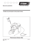
® ProjectPro 119 Airless Sprayer Betriebsanleitung • Owner’s Manual • Manuel d’utilisateur • Manuale dell’utente • Manual de usuario • Gebruikshandleiding • Ejermanual • Användarmanual • Manual do Proprietário D I ..........2 GB . . . . . . . . . . 10 F . . . . . . . . . . 18 D GB F DK . . . . . . . . . . 50 . . . . . . . . . . 26 ES . . . . . . . . . . 34 S . . . . . . . . . . 58 NL . . . . . . . . . . 42 P . . . . . . . . . . 66 I ES NL DK S P 0108 © 2008 Wagner. All rights reserved. Form No. 0418846B 1 D A I B E C F G J H 2 2) 1) 3 3) 1) 2) 4 5 3) 1) (a) 1) 7 PRIME 2) (b) 3) O SPRAY 6 2) 2 8 2) + l 4) 5) PRIME 3) (a) SPRAY 1) (b) 9 10 2) PRIME SPRAY 1) 3) (a) l (b) SPRAY PRIME 11 B) A) 25 - 30 cm C) D) 25 - 35 cm 25 - 30 cm 3 25 - 30 cm 12 13 A) B) 14 1) 3) 2) A) B) 15 (b) (c) (a) 16 17 (g) (a) (c) (b) (d) 4 (f) (e) (a) 18 19 1) 2) 2) 1) (b) (a) 20 1) 21 2) 1 3) 2 4 22 3 23 7 8 4 3 5 10 9 11 6 5 2 1 PP119 - Safety Information Warning! Attention: Danger of injury by injection! Airless units develop extremely high spraying pressures. Danger 1 Never put your fingers, hands or any other parts of the body into the spray jet! Never point the spray gun at yourself, other persons or animals. Never use the spray gun without safety guard. Do not treat a spraying injury as a harmless cut. In case of injury to the skin through coating materials or solvents, consult a doctor immediately for quick and expert treatment. Inform the doctor about the coating material or solvent used. 2 The operating instructions state that the following points must always be observed before starting up: 1. Faulty units must not be used. 2. Secure WAGNER spray gun using the safety catch on the trigger. 3. Ensure that the unit is properly earthed. The connection must take place through a correctly earthed two-pole and earth socket outlet. 4. Check allowable operating pressure of high-pressure hose and spray gun. 5. Check all connections for leaks. 3 The instructions regarding regular cleaning and maintenance of the unit must be strictly observed. Before any work is done on the unit or for every break in work the following rules must be observed: 1. Release the pressure from spray gun and hose. 2. Secure the WAGNER spray gun using the safety catch on the trigger. 3. Switch off unit. Be safety-conscious! 6 PP119 - Safety Information All local regulations in force must be observed. For secure handling of Airless high-pressure spraying units the following safety regulations are to be observed: U Flash point Danger U Explosion protection Danger U Do not use the unit in work places which are covered to the explosion protection regulations. Danger of explosion and fire through sources of flame during spraying work Danger U Only use coating materials with a flash point of 21 °C or above without additional heating. The flash point is the lowest temperature at which vapors develop from the coating material. These vapors are sufficient to form an inflammable mixture over the air above the coating material. There may be no sources of flame such as, for example, open fires, smoking of cigarettes, cigars or tobacco pipes, sparks, glowing wires, hot surfaces, etc. in the vicinity. Danger of injury through the spray jet U Danger U Caution! Danger of injury through injection! Never point the spray gun at yourself, other persons or animals. Never use the spray gun without spray jet safety guard. The spray jet may not come into contact with any part of the body. All hoses, fittings, and filter parts must be secured before operating spray pump. Unsecured parts can eject at great force or leak a high pressure fluid stream causing severe injury. In working with Airless spray guns, the high spray pressures arising can cause very dangerous injuries. If contact is made with the spray jet, coating material can be injected into the skin. Do not treat a spray injury as a harmless cut. In the case of injury to the skin through coating material or solvents, consult a doctor for quick and correct treatment. Inform the doctor about the coating material or solvent used. U Secure spray gun against unintended operation Always secure the spray gun when mounting or dismounting the tip and in case of interruption to work. In case of high operating pressure, pulling the trigger can effect a recoil force of up to 15 N. If you are not prepared for this, your hand can be thrust backwards or your balance lost. This can lead to injury. Respiratory protection for protection against vapors of solvents Wear respiratory protection when spraying. The user must be provided with a breathing mask. U Prevention of occupational illnesses Protective clothing, gloves and possibly skin protection cream are necessary for the protection of the skin. Observe the regulations of the manufacturer concerning coating materials, solvents and cleaning agents in preparation, processing and cleaning units. U Max. operating pressure Max. permissible operating pressure for spray gun, spray gun accessories and high-pressure hose may not fall short of the maximum operating pressure of 200 bar (20 MPa) stated on the unit. U Danger Recoil of spray gun High-pressure hose (safety note) Electrostatic charging of spray guns and the high-pressure hose is discharged through the high-pressure hose. For this reason the electric resistance between the connections of the high-pressure hose must be equal or lower than 197 kΩ/m (60 kΩ/ft.). i U For reasons of function, safety and durability use only original WAGNER high-pressure hoses. Electrostatic charging (formation of sparks or flame) Danger Under certain circumstances, electrostatic charging can occur on the unit due to the rate of flow of the coating material when spraying. On discharging this can result in the emergence of sparks or fire. It is therefore necessary that the unit is always earthed through the electrical installation. The connection must take place through a correctly earthed two-pole-and-earth socket outlet. U Using unit on construction sites Connection to the mains only through a special feed point, e.g. through an error protection installation with INF ≤ 30 mA. U Setting up the unit When working indoors: Vapors containing solvents may not be allowed to build up in the area of the device. Setting up the unit on the side a way from the sprayed object. Danger PP119 - Safety Information U A minimum distance of 5 m between the unit and spray gun is to be maintained. When working outdoors: Vapors containing solvents may not be allowed to blow toward the unit. Note the direction of the wind. Set the unit up in such a way that vapors containing solvents do not reach the unit and build up there. A minimum distance of 5 m between the unit and spray gun is to be maintained. Cleaning units with solvents Danger U Cleaning the unit Danger U Ventilation when spraying in rooms When cleaning the unit with solvents, the solvent should never be sprayed or pumped back into a container with a small opening (bunghole). An explosive gas/air mixture can be produced. The container must be earthed. Danger Danger of short circuit through penetrating water! Never spray down the unit with high-pressure or high-pressure steam cleaners. Adequate ventilation must be guaranteed for the removal of the solvent vapors. U U Only have this work carried out by a qualified electrician. No liability will be taken for incorrect installation. Suction installations These are to be set-up by the user of the unit according to local regulations. U U Earthing of the object Work or repairs on the electrical equipment Working on electrical components Remove the mains plug from the socket for all such works. The object to be coated must be earthed. Components and Description The shipping carton for your painting system contains the following: • Suction tube and return tube • Spray tip assembly • Inlet filter • 15 m, 6.35 mm diameter pressure hose • Spray gun with two filters • Instruction manual Figure 1 - Controls and Functions Item A) B) C) D) E) F) G) H) I) J) ComponentDescription. Description ON / OFF Switch.............................The ON/OFF switch turns the power to the sprayer on and off (O=OFF, l=ON). PRIME / SPRAY Knob.....................The PRIME/SPRAY knob directs fluid to the spray hose when set to SPRAY or the return tube when set to PRIME. The arrows on the PRIME/SPRAY knob shows the rotation directions for PRIME and SPRAY. The PRIME/SPRAY knob is also used to relieve pressure built up in the spray hose (see Pressure Relief Procedure). Sureflo™ Valve.................................The Sureflo™ valve is designed to keep the inlet valve open and from sticking due to dried materials. The Sureflo™ valve is activated automatically every time you turn the ON/OFF switch ON. PressureTrac™.................................The PressureTrac™ regulates the amount of force the pump uses to push the fluid. Pump Section..................................A piston in the pump section moves up and down to create the suction that draws fluid through the suction tube. Suction Tube...................................Fluid is drawn through the suction tube into the pump. Return Tube.....................................Fluid is sent back out through the return tube to the original container when PRIME/SPRAY knob is in PRIME position. Inlet filter...........................................The inlet filter strains the spray material to prevent the system from becoming clogged. Spray Gun.........................................The spray gun controls the delivery of the fluid being pumped. Spray Hose.......................................The spray hose connects the gun to the pump. 8 PP119 Assembly Figure 2 - Unfolding the Cart 1. Grab the pail bracket to lift up the sprayer. Lift the leg lock and unfold the legs. 2. Move leg lock down to lock into place. 3. Twist the knob on either side of the cart toward the “UP” arrow until it stops. Lift the handle until the motor housing and handle locks into place. Be careful not to pinch the power cord with the cart. 1. Thread the high pressure hose to the spray hose port. Tighten with an adjustable wrench. 2. Thread the other end of the hose to the spray gun. Hold the gun with one adjustable wrench, and tighten the hose nut with the other. i The spray tip should not be attached until after the sprayer and spray hose have been purged and primed. Figure 4 - Attaching the Suction Set 1. Remove cap from inlet valve (a). Thread the suction tube onto the inlet valve and tighten firmly by hand. Be sure that the threads are straight so that the fitting turns freely. 2. Press the return tube onto the return tube fitting. Squeeze clip (found in plastic bag) over the return tube fitting to secure the return tube. 3. Verify that the seal is present inside the suction tube. Thread the inlet filter into the end of the suction tube. The unit will begin to draw material up the suction tube, into the pump, and out the return tube. Let the unit cycle long enough to remove test fluid from the pump, or until spray material is coming from the return tube. i Figure 3 - Attaching the Hose 1. Place a full container of spraying material underneath the suction tube (a). Secure the return tube (b) into a waste container. 2. Slide the PressureTrac™ to maximum pressure (+). 3. Turn the PRIME/SPRAY knob to PRIME. 4. Plug in the sprayer and move the ON/OFF switch to the ON (l) position. 5. Switch the pump OFF (O). Remove the return tube from the waste container and place it in its operating position above the container of spraying material. Use the metal clip to bind the two hoses together. Figure 9 - Priming the Spray Hose 1. Unlock the spray gun and turn the PRIME/SPRAY knob to PRIME. i The spray tip should not be attached to your spray gun when purging your spray hose. 2. PULL the trigger and aim the spray gun at the side wall of a waste container. If using oil-based materials, the spray gun must be grounded while purging (see warning below). Before You Begin Figure 5 - Locking the Spray Gun Danger Danger 3. While pulling the trigger, switch the pump ON (l), and turn the PRIME/SPRAY knob to Spray. Hold the trigger until all air, water, or solvent is purged from the spray hose and material is flowing freely. Always lock the trigger off when attaching the spray tip or when the spray gun is not in use. 1. The gun is secured when the trigger lock is at a 90° angle (perpendicular) to the trigger in either direction. Danger Figure 6 - Pressure Relief Procedure Danger Priming Figure 7 - Preparing to Prime 1. Before priming, squirt a teaspoon of separating oil into the indicated area. Light household oil can be substituted if necessary. i The PP119 has the Sureflo™ valve that will activate automatically when the pump is turned ON (l). Figure 8 - Priming the Sprayer If the PRIME/SPRAY knob is still on SPRAY, there will be high pressure in the hose and spray gun until the PRIME/SPRAY knob is turned to PRIME. 4. Release trigger. Turn the prime/spray knob to PRIME. Turn the pump OFF (O). Trigger the gun into the waste container to be sure that no pressure is left in the hose. Be sure to follow the Pressure Relief Procedure when shutting the unit off for any purpose. This procedure is used to relieve pressure from the spray hose. 1. Lock the spray gun off. Flip the ON/OFF switch to the OFF position. 2. Turn the PRIME/SPRAY knob to PRIME. 3. Unlock the spray gun and trigger spray gun into the side of the material bucket. Lock the spray gun. Keep hands clear from fluid stream. Ground the gun by holding it against the edge of a metal container while flushing. Failure to do so may lead to a static electric discharge which may cause a fire. Figure 10 - Attaching the Spray Tip Danger POSSIBLE INJECTION HAZARD. Do not spray without the tip guard in place. Never trigger the gun unless the tip is in either the spray or the unclog position. Always engage the gun trigger lock before removing, replacing or cleaning tip. 1. Lock the spray gun off. 2. Thread the tip guard onto the gun. i When attaching the tip guard to the gun, align the tip guard as shown in figure 10 (a), then tighten by hand (b). Spraying PP119 Figure 11 - Spraying Technique A) The key to a good paint job is an even coating over the entire surface. Keep your arm moving at a constant speed and keep the spray gun at a constant distance from the surface. The best spraying distance is 25 to 30 cm between the spray tip and the surface. B) Keep the spray gun at right angles to the surface. This means moving your entire arm back and forth rather than just flexing your wrist. C) Keep the spray gun perpendicular to the surface, otherwise one end of the pattern will be thicker than the other. D) Trigger gun after starting the stroke. Release the trigger before ending the stroke. The spray gun should be moving when the trigger is pulled and released. Overlap each stroke by about 30%. This will ensure an even coating. i When finished spraying, perform Pressure Relief Procedure. i If you expect to be away from your spray project for more than 1 hour, follow the Short Term Cleanup procedure described in the Cleanup section of this manual. Cleanup Follow these steps when using latex materials only. If using materials that are oil-based, follow the Cleanup and Long-Term Storage steps. 1. Perform the Pressure Relief Procedure (see figure 6) and unplug the sprayer. 2. Pour 1/2 cup water slowly on the top of the paint to prevent the paint from drying. 3. Wrap the spray gun assembly in a damp cloth and place it in a plastic bag. Seal the bag shut. Place the sprayer in a safe place out of the sun for short-term storage. B) Startup 1. Remove the gun from the plastic bag. Stir the water into the paint. 2. Turn the PRIME/SPRAY knob to PRIME. 3. Plug sprayer in. 4. Turn the switch to ON (I). 5. Turn the PRIME/SPRAY knob to SPRAY. Test the sprayer on a practice piece and begin spraying. Figure 15 - Flushing the System 1. Lock the gun and remove spray tip assembly. Submerge suction set into a bucket with appropriate cleaning solution (a). 2. Place a waste container (b) next to the original material container (c). The containers should be touching. Aim the spray gun into the side of the original material container (c) and hold the trigger. 3. While pulling the gun trigger, turn the pump ON (l), and turn the PRIME/ SPRAY knob to SPRAY to purge material from the hose back into the original container. Keep holding trigger through next steps. 4. When cleaning solution flows from the spray gun, keep holding the trigger and aim the spray gun into the side of the waste container (ground gun with a metal container if flushing with flammable solvent). 5. Trigger the gun until the fluid flowing out of the gun is clear. You may need to dispose and obtain new cleaning solution. 6. Turn the PRIME/SPRAY knob to PRIME and trigger gun to relieve pressure. If the spray pattern becomes distorted or stops completely while the gun is triggered, follow these steps. Do not attempt to unclog or clean the tip with your finger. High pressure fluid can cause injection injury. 1. Release the trigger and lock the gun off. Rotate the reversible tip arrow 180º so that the point of the arrow is toward the rear of the gun (see figure 13). i Do not use mineral spirits or paint thinner on latex materials, or the mixture will turn into a jelly-like substance which is difficult to remove. A) Shutdown Figure 13 - Unclogging the Spray Tip Danger i i 1. Be sure that the paint hose is free of kinks and clear of objects with sharp cutting edges. 2. Slide the PressureTrac™ to its to its lowest setting. 3. Turn the PRIME/SPRAY valve to SPRAY. 4. Slide the PressureTrac™ to its highest setting. The paint hose should stiffen as material begins to flow through it. 5. Unlock the spray gun. 6. Trigger the spray gun to bleed air out of the hose. 7. When material reaches the spray tip, spray a test area to check the spray pattern. 8. Use the lowest pressure setting necessary to get a good spray pattern (A). If the pressure is set too high, the spray pattern will be too light. If the pressure is set too low, tailing will appear or the paint will spatter out in blobs rather than in a fine spray (B). i i If you used latex spray materials, use warm, soapy water to clean the sprayer. If you used oil-based spray materials, use mineral spirits. Figure 14 - Short Term Cleanup Figure 12 - Practice is clean, material will come out in a straight, high pressure stream. 4. Release the trigger and lock the gun off. Reverse the tip so the arrow points forward again. Unlock the gun and resume spraying. Under pressure, the spray tip may be very difficult to turn. Turn the PRIME/SPRAY knob to PRIME and trigger the gun. This will relieve pressure and the tip will turn more easily. 2. Turn the prime/spray knob to spray. 3. Unlock the gun and squeeze the trigger, pointing the gun at a scrap piece of wood or cardboard. This allows pressure in the spray hose to blow out the obstruction. When the nozzle 10 PP119 Figure 16 - Cleaning the Spray Gun 1. Make sure the pump is switched OFF (O). Make sure the PRIME/SPRAY knob is turned to PRIME. Unplug the sprayer. 2. Remove spray gun from the paint hose using adjustable wrenches. 3. Unclip the trigger guard (a) from the filter housing (b) by pulling outward from the filter housing. Unscrew the filter housing. 4. Remove the filter (c) from the spray gun housing and clean with the appropriate cleaning solution (warm, soapy water for latex paints, mineral spirits for oil-based materials). 5. Remove spray tip (d) from spray guard assembly. Clean spray tip with a soft-bristled brush and the appropriate cleaning solution. Be sure to remove and clean the washer (e) and saddle seat (f) located in the rear of the spray tip assembly. 6. Replace the cleaned filter, tapered end first, into the gun housing. The tapered end (g) of the filter must be loaded properly into the gun. Improper assembly will result in a plugged tip or no flow from the gun. 7. Install spray tip (d), saddle seat (f) and washer (e), and replace spray guard assembly. 8. Thread the spray gun back onto the paint hose. Tighten with a wrench. Figure 20 - Folding the Cart Figure 21 - Spray Gun/Spray Hose Item 1 2 3 4 Part # 0418722 Part # 0418705 0418706 0418707 0418708 0418709 0418710 Description..................................... Quantity Suction set assembly..............................................1 0418711 0418712 0418713 0418716 Description Spray tip, XS . ......................... Water-soluble and solvent based enamels and paints, oils and release agents Spray tip, S ............................. Synthetic resin-based paints, PVC paints Spray tip, M ............................ Enamel paints, undercoats, primers, fillers, indoor latex paints and indoor emulsions Spray tip, L . ............................ Enamel paints, undercoats, primers, fillers, indoor latex paints and indoor emulsions, anti-corrosive paints Spray tip, XL ........................... Enamel paints, undercoats, primers, fillers, indoor latex paints and indoor emulsions, anti-corrosive paints) Spray tip, XXL ........................ Enamel paints, undercoats, primers, fillers, indoor latex paints and indoor and outdoor emulsions, anti-corrosive paints, flame retardants Filter, XS - S (2 pack) Filter, M (2 pack) Filter, L - XXL+ (2 pack) Pump section refurbishing kit All spare parts listed above are wear parts, and are not covered by warranty. Figure 19 - Cleaning the Inlet Valve Description..................................... Quantity Complete gun assembly........................................1 Tip, XL...........................................................................1 Filter, L - XXL+............................................................2 Spray hose, 15m, yellow........................................1 Accessories 1. Fill a cup or other container with separating oil or light household oil and submerge the inlet valve into the oil. 2. Place a rag over the spray hose port, and turn the switch ON (l). When the oil has been pumped from the cup, turn the pump OFF (O). 3. Fully insert the Sureflo™ valve. 4. Wipe the entire unit, hose and gun with a damp cloth to remove accumulated paint. Replace the high pressure hose to the paint hose port. i Part # 0418717 0418709 0418713 0418720 Figure 22 - Spray Gun/Spray Hose 1. Lock the gun and turn the pump OFF (O). Turn the PRIME/ SPRAY knob to PRIME. 2. Remove the suction hose and return tube and clean them by hand using the appropriate cleaning solution. You should also wipe the threads of the inlet nut (a) and remove and clean the inlet filter at the suction set. 3. When suction set is clean, thread the suction tube back into the inlet valve, and replace the return tube onto the return tube fitting (see figure 3). Replace clip. 4. Submerge the suction hose and return tube into a bucket of new cleaning solution. 5. Turn the PRIME/SPRAY knob to PRIME. Turn the pump ON (l), and trigger the gun into a waste container to relieve pressure. 6. Let the pump circlulate cleaning solution through the suction set for 2-3 minutes. Turn the pump OFF. Figure 18 - Long-Term Storage 1. With one hand on the handle, twist the knob on either side of the cart toward the “DOWN” arrow. 2. When the knob is fully “DOWN”, this will release the handle and it can be folded down until it is locked into place. Be careful not to pinch the power cord with the cart. 3. Lift the leg lock, and fold the legs in. Replace the leg lock to hold the legs into place (inset). Parts Lists Figure 17 - Cleaning the Suction Set 2. Unscrew the inlet valve assembly (b) from the sprayer. Visually inspect the inside and outside of the inlet valve assembly. Clean any paint residue with the appropriate cleaning solution. 3. Replace inlet valve assembly by screwing it into the sprayer. 4. Replace Sureflo™ valve solenoid. Cleaning or servicing the inlet valve may be required if the unit has priming problems. Priming problems may be prevented by properly cleaning the sprayer and following the long-term storage steps. 1. Remove the suction hose and return tube. Loosen the fitting as shown (a) and remove the Sureflo™ valve solenoid. 11 PP119 Figure 23 - Pump section replacement instructions Kit Part Number 0418716 Danger Always wear protective eye wear while servicing the pump. Be sure to follow the Pressure Relief Procedure when shutting the unit down for any purpose, including servicing or adjusting. After performing the Pressure Relief Procedure, be sure to unplug the unit before servicing or adjusting. Area must be free of solvents and paint fumes. Disassembly of the Pump Section 9. Install the yoke screw (1) and washer (2) to secure the dowel pin. 10. Turn pump right side up and apply a few drops of Separating Oil or light household oil between the top nut (7) and piston (5). This will prolong the seal life. 11. Install front cover and three (3) screws. 12. Install the inlet valve assembly. Install the suction set. 1. Remove the suction set. 2. Remove the front cover and the three screws that secure it using a T20 Torx head driver. 3. Remove the yoke screw (1) and washer (2) that secures the dowel pin (3). The dowel pin connects the yoke (4) to the piston (5). 4. Using a pliers, pull the dowel pin out. 5. Inspect the yoke assembly and piston. In order to remove all the necessary parts, the piston must not be in the bottom dead center position. If the piston is at the bottom of the stroke, install the front cover and screws, turn the pump on briefly to index the piston, unplug the unit, and repeat step 2. 6. Unscrew and remove the inlet valve assembly (6). 7. Remove the piston assembly by pushing down on the piston near the yoke. 8. Unscrew and remove the top nut (7) using and adjustable wrench. 9. Remove the worn seals using a flat head screwdriver or punch. Remove the top seal (8) from the top and the bottom seal (9) from the bottom by pressing against the side of the seal and popping it out. Be sure not to scratch the housing where the seals are located. 10. Clean the area where the new seals are to be installed. Danger Danger 1. Lubricate the new top seal (8) with Separating Oil or light household oil and by hand place the seal (cup side of seal down) into the top port of the housing. 2. Place a small amount of bearing grease on the threads of the top nut (7). Place the top nut into the top of the housing and tighten with an adjustable wrench. This will drive the top seal into the correct position. 3. Turn the pump upside down. Lubricate the seal on the piston/ seal assembly (5, 9) similar to the top seal. Place the piston/ seal assembly into the bottom of the housing. i Do not connect the blue or brown wire to the earth terminal of the plug! The wires in this mains lead are coloured in accordance with the following code: blue = live brown = live As the colours of the wires in the mains lead of this appliance may not correspond with the coloured markings identifying the terminals in your plug, proceed as follows: Assembly of the Pump Section If the supply cord of this appliance is damaged, it must only be replaced by a repair shop appointed by the manufacturer, because special purpose tools are required. • Should the moulded plug have to be replaced, never re-use the defective plug or attempt to plug it into a different 13A socket. This could result in an electric shock. • Should it be necessary to exchange the fuse in the plug only use fuses approved by ASTA in accordance with BS 1362. Ten (10) Amp fuses may be used. • To ensure that the fuse and fuse carrier are correctly mounted, please observe the provided markings or colour coding in the plug. • After changing the fuse, always make sure that the fuse carrier is correctly inserted. Without the fuse carrier, it is not permissible to use the plug. • The correct fuses and fuse carriers are available from your local electrical supplies stocklist. DO NOT attempt to remove the bottom seals from the new piston. Fit a BS 1363A approved plug 4. Insert the insertion tool (10) and thread into position to properly seat the piston/seal. Thread fully until tight. Remove the insertion tool. 5. Install the new O-ring (11) on the inlet valve assembly, lubricate with Separating Oil or light household oil, thread into the bottom (inlet) of the housing, and tighten with an adjustable wrench. This will drive the bottom seal into the correct position. 6. Align the piston (5) with the yoke (4). Be careful not to damage the piston. 7. Apply a bearing grease to the holes in the yoke where the dowel (3) is inserted. 8. Install the dowel pin (3) to connect the yoke to the piston. The piston may have to be moved up or down to do this. The inlet valve may need to be removed again to move the piston. Blue to be connected to N (neutral) Make sure that the outer sheath of the cable is held firmly by the clamp 12 Fit the recommended fuse Brown to be connected to L (live) NEVER use a light socket PP119 - Troubleshooting / Maintenance Problem Cause Solution A.The sprayer does not start. 1. The sprayer is not plugged in. 2. The ON/OFF switch is set to OFF. 3. The sprayer was turned off while still under pressure. 4. No voltage is coming from the wall plug. 5. The extension cord is damaged or has too low a capacity. 6. A fuse is blown in the sprayer. 7. There is a problem with the motor. 1. Plug the sprayer in. 2. Turn the ON/OFF switch to ON. 3. Slide the PressureTrac™ to maximum pressure (+), or relieve pressure by turning the PRIME/SPRAY valve to PRIME. 4. Properly test the power supply voltage. 5. Replace the extension cord. 6. Take the sprayer to an Authorized Service Center. 7. Take the sprayer to an Authorized Service Center. 1. Try to prime the unit again. 2. Refill the bucket or immerse the suction tube in paint. 1. The unit will not prime properly or has lost prime. 2. The paint bucket is empty or the suction tube is not totally immersed in the paint. 3. The suction set is clogged. 4. The suction tube is loose at the inlet valve. 5. The inlet valve is stuck. 6. The inlet valve is worn or damaged. 7. The PRIME/SPRAY valve is plugged. 3. Clean the suction set. 4. Clean the tube connection and tighten it securely. 5. Clean the inlet valve. Inlet may be stuck from old paint. Operate Sureflo™ valve to release. 6. Install pump section refurbishing kit*. 7. Take the sprayer to an Authorized Service Center. 1. The spray tip is worn. 2. The inlet filter is clogged. 3. The gun filter is plugged. 4. The paint is too heavy or coarse. 5. The inlet valve assembly is damaged or worn. B. The sprayer starts but does not draw in paint when the PRIME/ SPRAY knob is set to PRIME. C. The sprayer draws up paint but the pressure drops when the gun is triggered. D. The PRIME/SPRAY valve is on SPRAY and there is flow through the return tube. 1. The PRIME/SPRAY valve is dirty or worn. E. The spray gun leaks. 1. Internal parts of the gun are worn or dirty. F. The tip assembly leaks. 1. The tip was assembled incorrectly. 2. A seal is dirty. G. The spray gun will not spray. 1. The spray tip or the gun filter is plugged. 2. The spray tip is in the reverse position. H. The paint pattern is tailing. 1. The pressure is set too low. 2. The gun filter, the tip, or the suction filter is plugged. 3. The suction tube is loose at the inlet valve. 4. The tip is worn. 5. The paint is too thick. 6. Pressure loss. 1. Replace the spray tip with a new tip.* 2. Clean the inlet filter.. 3. Clean or replace the proper filter. Always keep extra filters on hand. 4. Thin or strain the paint. 5. Install pump section refurbishing kit*. 1. Take the sprayer to an Authorized Service Center. 1. Take the sprayer to an Authorized Service Center. 1. Check the tip assembly and assemble properly. 2. Clean the seal. 1. Clean the spray tip or gun filter. 2. Put the tip in the forward position. 1. Increase the pressure. 2. Clean.. 3. 4. 5. 6. Tighten the suction tube fitting. Replace the spray tip. Thin the paint. Refer to Causes and Solutions for problem C. * Special repair kits with instructions are available for these procedures. Refer to the Accessories section of this manual for a list of the kits and their part numbers. Daily Maintenance The only daily maintenance necessary is thorough cleaning and lubricating after usage. Follow the cleaning and lubricating procedures in this manual. Extended Maintenance Some pump parts eventually wear out from use and must be replaced. However, pump performance is the only reliable indicator of when to replace wear parts. Refer to the Troubleshooting section for more information on when to use these kits. 13 D GB Wichtiger Hinweis zur Produkthaftung Important notes on product liability Garantieerklärung Guarantee declaration Aufgrund einer ab 01.01.1990 gültigen EU-Verordnung haftet der Hersteller nur dann für sein Produkt, wenn alle Teile vom Hersteller stammen oder von diesem freigegeben wurden, bzw. die Geräte sachgemäß montiert und betrieben werden. Bei Verwendung von fremdem Zubehör und Ersatzteilen kann die Haftung ganz oder teilweise entfallen; in extremen Fällen kann von den zuständigen Behörden (Berufsgenossenschaft und Gewerbeaufsichtsamt) der Gebrauch des gesamten Gerätes untersagt werden. Mit Original WAGNER Zubehör und Ersatzteilen haben Sie die Gewähr, dass alle Sicherheitsvorschriften erfüllt sind. As a result of an EC regulation being effective as from January 1, 1990, the manufacturer shall only be liable for his product if all parts come from him or are released by him, and if the devices are properly mounted and operated. If the user applies outside accessories and spare parts, the manufacturer´s liability can fully or partially be inapplicable; in extreme cases usage of the entire device can be prohibited by the competent authorities (employer´s liability insurance association and factory inspectorate division). Only the usage of original WAGNER accessories and spare parts guarantees that all safety regulations are observed. Die Garantie beträgt bei privater Nutzung 24 Monate, bei kommerzieller Nutzung 12 Monate. Übersteigt die mit dem Gerät verarbeitete Farbmenge 1000 Liter, wird dies einer kommerziellen Nutzung gleichgestellt. Für dieses Gerät leisten wir Werksgarantie in folgendem Umfang: Alle diejenigen Teile werden unentgeltlich nach unserer Wahl ausgebessert oder neu geliefert, die sich innerhalb der Garantiezeit seit Übergabe an den Käufer infolge eines vor dieser Übergabe liegenden Umstandes- insbesondere wegen fehlerhafter Bauart, schlechter Baustoffe oder mangelhafter Ausführung – als unbrauchbar oder in ihrer Brauchbarkeit erheblich beeinträchtigt erweisen. Wir übernehmen keine Garantie für Schäden die durch folgende Gründe mit verursacht worden sind: Ungeeignete oder unsachgemäße Verwendung, fehlerhafte Montage, bzw. Inbetriebsetzung durch den Käufer oder durch Dritte, natürliche Abnutzung - Verschleißteile fallen nicht unter die WAGNER Garantie, fehlerhafte Behandlung insbesondere mangelnde Reinigung oder Wartung, ungeeignete Beschichtungsstoffe, Austauschwerkstoffe und chemische, elektrochemische oder elektrische Einflüsse, sofern die Schäden nicht auf ein Verschulden von uns zurückzuführen sind. Schmirgelnde Beschichtungsstoffe, wie beispielsweise Dispersionen, Glasuren, Quarzgrund, abrasive Materialien o. ä. verringern die Lebensdauer von Ventilen, Packungen, Spritzpistole, Düsen, Zylinder, Kolben, Filter, Schläuche, Dichtungen, etc.. Hierauf zurückzuführende Verschleißerscheinungen sind durch diese Garantie nicht gedeckt. Das Gerät ist für den Einsatz im Schichtbetrieb als auch für die Vermietung, den Verleih nicht konzipiert – diese Verwendungen sind von der Garantie ausgeschlossen. Der Austausch eines Teils verlängert nicht die Garantiezeit des Gerätes. Das Gerät ist unverzüglich nach Empfang zu untersuchen. Offensichtliche Mängel sind bei Vermeidung des Verlustes der Mängelrechte innerhalb von 14 Tagen nach Empfang des Gerätes schriftlich mitzuteilen. Wir behalten uns vor, die Garantie durch ein Vertragsunternehmen erfüllen zu lassen. Reparaturen oder Instandsetzungsarbeiten, die weitergehen als in dieser Bedienungsanleitung angegeben, behalten wir uns im Werk vor. Wenden Sie sich im Garantie- oder Reparaturfall bitte an den Fachhändler, bei dem Sie das Gerät erworben haben. Die Leistung der Garantie ist abhängig vom Nachweis durch Rechnung, Lieferschein bzw. Kaufbeleg. Ergibt die Prüfung, dass kein Garantiefall vorliegt, so geht die Reparatur zu Lasten des Käufers. The guarantee period amounts to 24 months in case of private use, and to 12 months in case of commercial use. If the amount of paint processed with the unit exceeds 1,000 litres, this is considered to be commercial use. We give a works guarantee to the following extent for this unit: All those parts that prove to be unserviceable or to be considerably impaired in their serviceability within the guarantee period since the point of handing over to the buyer due to a circumstance lying before this handing over – in particular due to faulty design, bad building materials or poor execution – are improved or supplied new as we choose without costs. We do not accept any guarantee for damage that has been caused by the following reasons: Unsuitable or incorrect usage, faulty mounting or starting-up by the buyer or by third parties, natural wear - wear parts are not covered by the WAGNER guarantee , faulty handling in particular inadequate cleaning or maintenance, unsuitable coating materials, substitute materials and chemical, electrochemical or electrical influences, in as far as damage is not due to our fault. Abrasive coating materials, such as dispersions, glazes, quartz undercoats, abrasive materials, etc. reduce the durability of valves, packings, spray guns, tips, cylinders, pistons, filters, hoses, seals, etc. Any resulting signs of wear are not covered by this guarantee. The unit is not conceived for use in shift work or for lending or leasing – these uses are excluded from the guarantee. The replacement of a part does not extend the guarantee period of the unit. The unit has to be examined immediately after receipt. Obvious faults are to be reported in writing within 14 days after receipt of the unit in order to avoid loss of the rights arising from faults. We reserve the right to have the guarantee fulfilled by a contractual company. Repairs going above and beyond those dealt with in these operating instructions are reserved for our factory. In case of a guarantee case or repair, please contact the specialist dealer from whom you purchased the unit. Fulfilling of the guarantee depends on proof being provided by invoice and delivery note or proof of purchase. If the check shows that the case is not a guarantee case, repairs are carried out at the expense of the buyer. Claims against Wagner that are based on or caused by the failure or insufficiency of a unit cannot be asserted. We make it clear that the guarantee declaration does not represent a limitation of the statutory rights or of the rights agreed contractually through our general terms of business. Ansprüche gegenüber Wagner, basierend, bzw. verursacht durch einen Geräteausfall bzw. Mangel können nicht geltend gemacht werden. J. Wagner GmbH Klargestellt wird, dass diese Garantieerklärung keine Einschränkung der gesetzlichen, bzw. der durch unsere allgemeinen Geschäftsbedingungen vertraglich vereinbarten Ansprüche darstellt. Not responsible for errors and changes J. Wagner GmbH Änderungen und Irrtümer vorbehalten 14 Entsorgungshinweis: Gemäß der europäischen Richtlinie 2002/96/EG zur Entsorgung von Elektro-Altgeräten, und deren Umsetzung in nationales Recht, ist dieses Produkt nicht über den Hausmüll zu entsorgen, sondern muss der umweltgerechten Wiederverwertung zugeführt werden! Ihr Wagner-Altgerät wird von uns, bzw. unseren Handelsvertretungen zurückgenommen und für Sie umweltgerecht entsorgt. Wenden Sie sich in diesem Fall an einen unserer Service-Stützpunkte, bzw. Handelsvetretungen oder direkt an uns. Indicazione per lo smaltimento: Secondo la direttiva europea 2002/96/CE per lo smaltimento di vecchi apparecchi elettrici e la sua conversione nel diritto nazionale, questo prodotto non va smaltito attraverso i rifiuti domestici, bensì va smaltito portandolo al riutilizzo in conformità della tutela ambiente! Il Vs. apparecchio vecchio Wagner verrà preso indietro da noi risp. dalle nostre rappresentanze commerciali e smaltito per Voi in conformità della tutela ambiente. In questo caso rivolgetevi ad uno dei nostri punti di servizio per l’assistenza clienti, risp. ad una delle nostre rappresentanze commerciali oppure direttamente a noi. Note on disposal: In observance of the European Directive 2002/96/ EC on waste electrical and electronic equipment and implementation in accordance with national law, this product is not to be disposed of together with household waste material but must be recycled in an environmentally friendly way! Wagner or one of our dealers will take back your used Wagner waste electrical or electronic equipment and will dispose of it for you in an environmentally friendly way. Please ask your local Wagner service centre or dealer for details or contact us direct. Aanwijzing voor afvalverwerking: Conform de Europese Richtlijn 2002/96/EG voor afvalverwerking van oude elektrische apparatuur en diens uitvoer volgens nationaal recht, mag dit product niet in het huisval worden gedeponeerd, en dient het milieuvriendelijk te worden gerecycled! Uw oude Wagner-apparaat wordt door ons resp. onze handelsvertegenwoordigingen teruggenomen en op de betreffende inzamelpunten gedeponeerd. Wendt u zich in dit geval aan één van onze service-contactpunten, resp. handelsvertegenwoordigingen of direct aan ons. Consignes d’élimination: Selon la directive européenne 2002/96/CE sur l’élimination des vieux appareils électriques et sa conversion en droit national, ce produit ne peut pas être jeté dans les ordures ménagères, mais est à amener à un point de recyclage en vue d’une élimination dans le respect de l’environnement! Wagner, resp. nos représentations commerciales reprennent votre vieil appareil Wagner pour l’éliminer dans le respect de l’environnement. Adressez-vous donc directement à nos points de service resp. représentations commerciales ou directement à nous. Henvisning vedrørende bortskafning: I henhold til det europæiske direktiv 2002/96/ EF vedrørende bortskafning af gamle elektriske apparater og direktivets optagelse i national lovgivning må dette produkt ikke bortskaffes sammen med husholdningsaffald. Af hensyn til miljøet skal det afleveres på et genbrugscenter. Vi hhv. vore forhandlere tager imod Deres gamle Wagnerapparat, hvorefter det bortskaffes på miljøvenlig måde. Henvend Dem i dette tilfælde til et af vores service-centre, vore forhandlere eller direkte til os. Observación sobre la eliminación de residuos: De acuerdo con la directriz europea 2002/96/CE referente a la eliminación de aparatos eléctricos usados y su puesta en la práctica en el derecho nacional, este producto no se deberá eliminar en la basura doméstica, ¡sino que se deberá llevar a una planta de reciclaje ecológico! Su aparato usado de Wagner nos lo puede entregar a nosotros o a una de nuestras agencias comerciales, del resto nos ocupamos nosotros, es decir, de la eliminación ecológica de los residuos. Diríjase en este caso a uno de nuestros centros de asistencia técnica o a una de nuestras agencias comerciales o bien directamente a nosotros. Information om avfallshantering: Enligt det europeiska direktivet 2002/96/EG om avfall som utgörs av eller innehåller elektriska eller elektroniska produkter och tillämpningen av detta inom nationell rättspraxis, skall denna produkt inte kastas i hushållssoporna, utan måste återvinnas på ett miljövänligt sätt! Din färdiganvända utrustning från Wagner återtas av oss eller våra agenturer och avfallshanteringen sköts sedan på ett miljövänligt sätt. Vänd dig till något av våra serviceställen, agenturer eller direkt till oss. 15 D I Konformitätserklärung Dichiarazione di conformità Hiermit erklären wir, dass die Bauart von WAGNER Project Pro 119 folgenden einschlägigen Bestimmungen entspricht: 73/23 EWG, 89/336 EWG, 92/31 EWG, 93/68 EWG, 98/37 EWG. Angewendete harmonisierte Normen, insbesondere: EN 292-1/-2, EN 1953, EN 55014, EN 60335-1, EN 61000-3. Angewendete nationale technische Spezifikationen, insbesondere: –––––––– Datum: 17.12.2007 Si dichiare che il modello della WAGNER Project Pro 119 è conforme alle sequenti disposizioni pertinenti: 73/23 EWG, 89/336 EWG, 92/31 EWG, 93/68 EWG, 98/37 EWG. Norme armonizzate applicate, in particolare: EN 292-1/-2, EN 1953, EN 55014, EN 60335-1, EN 61000-3. Norme e specificazioni tecniche nazionali applicate in particolare: –––––––– Data: 17.12.2007 GB E Declaration of conformity Declaración de conformidad Herewith we declare that the supplied version of WAGNER Project Pro 119 Complies with the following provisons applying to it: 73/23 EWG, 89/336 EWG, 92/31 EWG, 93/68 EWG, 98/37 EWG. Applied harmonized standards, in particular: EN 292-1/-2, EN 1953, EN 55014, EN 60335-1, EN 61000-3. Por la presente, declaramos que la WAGNER Project Pro 119 satisface las disposiciones pertinentes siguientes: 73/23 EEG, 89/336 EEG, 92/31 EEG, 93/68 EEG, 98/37 EEG. Normas armonizadas utilizadas particularmente: EN 292-1/-2, EN 1953, EN 55014, EN 60335-1, EN 61000-3. Normas y especificaciones técnicas nacionales que se utilizaron, particularmente: –––––––––– Fecha: 17.12.2007 Applied national technical standards and specifications, in particular: –––––––– Date: 17.12.2007 F NL Déclaration de conformité Verklaring van overeenstemming Par la présente, nous déclarons, que le type de WAGNER Project Pro 119 Correspond aux dispositions pertinentes suivantes: 73/23 EWG, 89/336 EWG, 92/31 EWG, 93/68 EWG, 98/37 EWG. Normes harmonisée utilisées, notamment: EN 292-1/-2, EN 1953, EN 55014, EN 60335-1, EN 61000-3. Normes et specifications techniques nationales qui ont été utilisées, notamment: –––––––– Date: 17.12.2007 Hiermede verklaren wij, dat de in de handel gebrachte machine WAGNER Project Pro 119 voldoet aan de eisen van de in het vervolg genoemde bepalingen: 73/23 EEG, 89/336 EEG, 92/31 EEG, 93/68 EEG, 98/37 EEG. Gebruikte geharmoniseerde normen, in het bijzondere: EN 292-1/-2, EN 1953, EN 55014, EN 60335-1, EN 61000-3. Gebruikte nationale technische normen en specificaties, in het bijzondere: –––––––––– Datum: 17.12.2007 16 DK Overensstemmelseserklæring Hermed erklæres at produkttypen WAGNER Project Pro 119 er i overensstemmelse med følgende bestemmelser: 73/23 EØF, 73/23 EWG, 89/336 EWG, 92/31 EWG, 93/68 EWG, 98/37 EWG. Harmoniserede standarder, der blev anvendt, isærdeleshed: EN 292-1/-2, EN 1953, EN 55014, EN 60335-1, EN 61000-3. Nationale standarder og tekniske specificationer, der blev anvendt, i særdeleshed: –––––––– Dato: 17.12.2007 S konformitetsdeklaration Härmed intygar vi att WAGNER Project Pro 119 är konstruerad enligt följande gällande bestämmelser: 73/23 EEG, 89/336 EEG, 92/31 EEG, 93/68 EEG, 98/37 EEG. Tillämpade harmoniserade standarder, i synnerhet: EN 292-1/-2, EN 1953, EN 55014, EN 60335-1, EN 61000-3. Tillämpade nationella, tekniska specifikationer, i synnerhet: –––––––––– Datum: 17.12.2007 P Declaração de conformidade Declaramos com a presente que a versão fornecida de WAGNER Project Pro 119 Está em conformidade com as seguintes normas: 73/23 EEG, 89/336 EEG, 92/31 EEG, 93/68 EEG, 98/37 EEG. Normas harmonizadas aplicadas, em particular: EN 292-1/-2, EN 1953, EN 55014, EN 60335-1, EN 61000-3. Normas e especificações técnicas nacionais aplicadas, em particular: –––––––––– Data: 17.12.2007 Geschätfsführer Executive Officer Directeur Dirigente affaristico Gerente Directeur Forretningsfører Verkställande direktör Director Executivo Unterschrift Signature Signature Firma Firma Handtekening Underskrift Underskrift Assinatura 17 Entwicklungsleiter Head of Development Directeur du developpement Dirigente tecnico Jefe de Desarrollo Chef ontwikkeling Udviklingslede Utvecklingsledare Responsável pelo Desenvolvimento Hinweis • Notes • Remarques • Note • Notas • Opmerking • Bemærk • Anmärkning • Notas 18 Hinweis • Notes • Remarques • Note • Notas • Opmerking • Bemærk • Anmärkning • Notas 19 D J. Wagner GmbH Otto-Lilienthal-Str. 18 D-88677 Markdorf Hotline 0180/1000 227 CZ B Wagner Spraytech Belgie Veilinglaan 58 1861 Meise-Wolvertem E GB Wagner Spraytech (UK) Ltd. 3 Haslemere Way, Tramway Industrial Estate Banbury, Oxon OX16 5RN SLO DK/S Wagner Spraytech Scandinavia A/S Helgeshøj Allé 28 DK-2630 Tåstrup H Magyarországi szerviz Hondimpex KFT. Kossuth L. u. 48-50 8060 Mór J. Wagner AG Industriestraße 22 9450 Altstätten CZ PUT Wagner Service ul. E. Imieli 14 41-605 Swietochlowice +49/75 44 /505-0 +49/75 44/505-200 +420/2/57 95 04 12 +420/2/57 95 10 52 J. Wagner Spraytech Ibérica S.A. Ctra. N-340, Km 1245,4 08750 Molins de Rei (Barcelona) +34/93/6 80 00 28 +34/93/6 68 01 56 +32/2/2 69 46 75 +32/2/2 69 78 45 Adresa servisa: GMA Elektromehanika d.o.o. Cesta Andreja Bitenca 115, Ljubljana 1000/Slowenien +386(1)/583 83 04 +386(1)/518 38 03 +44/12 95/26 53 53 +44/12 95/27 54 87 +45/43 27 18 18 +45/43 43 05 28 CH Wagner Spol s.r.o. Nedašovská 345 15500 Praha 5 +36(-22)/407 321 +36(-22)/407 852 +41/71/7 57 22 11 +41/71/7 57 23 23 +48/32/2 45 06 19 +48/32/2 41 42 51 SK HR Phobos Corporation Spol.r.o Stanicna 6, 92700 Sala Slowakei +421/31/7 70 78 84 +421/31/7 70 22 42 NL Wagner Spraytech Benelux B.V. Zoonebaan 10 3542 EC Utrecht F Wagner France S.a.r.l. 5, Aveneu du 1er Mai 91122 Palaiseau +385(-1)65 86 - 028 / AUS Wagner Spraytech Australia Pty. Ltd., 14-16 Kevlar Close, Braeside, VIC 3195/Australia +61/3/95 87 20 00 +61/3/95 80 91 20 +31/30/2 41 41 55 +31/30/2 41 17 87 0825 011 11 Adresa servisa: EL-ME-HO Horvatinčićev put 2 10436 Rakov Potok/Kroatien 0169 81 72 57 www.wagner-group.com Irrtümer und Änderungen vorbehalten. Not responsible for errors and changes. Sous réserves d’erreurs et de modifications. Fouten en wijzigingen voorbehouden. Non responsabili per errori o modifiche Nous déclinons toute responsabilité en cas d’erreur ou de modification Ikke ansvarlig for fejl og ændringer Med reservation för feltryck och ändringar Sem responsabilidade por erros e alterações Part. No. 041 8846 02/2008_RS © Copyright by J.Wagner GmbH 20