1
another free manual from www.searstractormanuals.com
Sears
owners
manual
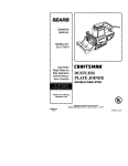
MODEL NO.
180.260250
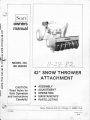
42" SNOW THROWER
ATTACHMENT
CAUTION:
Read Rules for
Safe Operation
and Instructions
Carefully!
•
•
e
•
•
ASSEMBLY
ADJUSTMENT
OPERATING
MAINTAINENCE
PARTS LISTING
Sears, Roebu ck and Co., Chicago, Ill. 60684 U.S.A.
M1 4-8002
PRINTED IN U.S.A.
12/ 80
-
------------~------~
ATTENTION!! ASSEMBLY TIME
another free manual from www.searstractormanuals.com
The initial time required to assemble and attach this Snow Thrower Attachment to your
tractor will consume approximately one and
one half (1-1/2) hours. Future assembly times
will be much less as you become famil iar
with the attachment.
TABLE OF CONTENTS
Assembly Instructions
Adjustment Instructions
Operating Instructions
Maintenance Instructions
Parts Listing
A
20-23
LOOK FOR THIS SYMBOL TO POINT OUT IM·
PORANT SAFETY PRECAUTIONS. IT MEANS
ATIENTION! BECOME ALERT! YOUR SAFE·
TV IS INVOLVED.
FULL ONE YEAR WARRANTY
For one year from th e date of purchase, Sears ·
~==~ ~ e-:
defect in material or workmanship in this tracw,.. ~ :: ~:--s-: e:
no charge.
If the tractor attachment is used for comfT'e'"::: a O '" ...e...,<a ou rposes, this warranty applies only thirty dats :,.om Lr.e oate o' pu rchase.
Warranty service is available at your l"lo,.,..e. at no ch arge. o;
simply contactin g the nearest Sears s<ore or Service Cen ~e ...
throughout the Un ited States.
This warranty gives you specific legal rights, and you may a sc
have other rights w hich vary from state to state.
Sear, Roebuck and Co.
Sears Tower
sse 41 -3
Chicago, IL 60684
2
RULES FOR SAFE OPERATION
1. Know the contro ls and how to stop quickly, READ THE
OWNER'S MANUAL,
2. Do not allow children to operate the vehicle. Do not
allow adults to operate without proper Instruction.
3. Do not carry passengers. Keep children and pets a safe
distance away.
another free manual from www.searstractormanuals.com
4. Always wear substantial footwear. Do not wear loose
fitting clothing that could get caught in moving parts.
5. Keep your eyes and mind on your tractor, snow thrower
and the area being cleaned. Don't let other interests
distract you.
6. Do not attempt to operate your tractor or mower when
not in the drivers seat.
7. Always get on or off your tractor from the operators.Jeft
hand side.
8. Clear the work area of objects which might be picked up
and thrown.
9. Disengage all attachment clutches and shift into neutral
before attempting to start the engine.
10. Disengage power to attachments and stop the engine
before leaving the operator's position.
11. Disengage all power to snow thrower, stop the engine
and disconnect spark plug wire (s) from spark plug (s)
before cleaning making an adjustment or repa1rs.
12. Disengage power to attachments when traospon .:-~g or
not in use. Drive slowly when front or rear rrounted
attachment is in transport position.
13. Take all possible precautions when leaving :he venicl e
unattended, such as disengaging the power-<aJ<e-off
lowering the attachments, shifting into neutral. setting
the parking brake, stopping the engine, and removing
the key.
14. Do not stop or start suddenly when going uphill or
downhill.
15. Reduce speed on slopes and make turns gradually to
prevent tipping or loss of control. Exercise extreme
caution when changing direction on slopes.
16. Do not shift gears while going up or down slopes.
Choose a gear low enough to negotiate the slope
without stopping and shifting gears. To reduce speed,
move throttle lever to slow.
17. Stay alert for holes in the terrain and other hidden
hazards .
18. Do not drive too close to creeks, ditches and public
highways.
19. Exercise special care when removing snow around fixed
objects in order to prevent the auger from striking
them. Never deliberately run tractor or mower Into or
over any foreign object.
20 . Never shift gears until tractor comes to stop.
21. Never place hands or feet near the snow thrower auger,
in the deflector (discharge chute) or near any moving
parts while tractor or mower are running. Always keep
clear of discharge chute.
22. Use care when pulling loads or using heavy equipment.
a.
b.
c.
d.
Use only approved draw bar hitch points.
Limit loads to those you can safely control.
Do not turn sharply. Use care when backing.
Use counterweights or wheel weights and tire
chains when suggested In this owner's manual.
e. Never run snow thrower into heavy material at high
speeds.
23. Watch out for traffic when crossing or near roadways.
24. When using any attachments, never direct discharge of
material toward bystanders nor allow anyone near the
vehicle while in operation.
25. Handle gasoline with care it is highly flammable.
a. Use approved gasol ine conta ners .
b . Never remove the cap of the iuel tank or add gasoline to a running or hot engire. or fill the fuel tank
indoors. Wipe up spilled gaso ~e
c. Open doors if the engine is r..,.-r :19 in the garage
exhaust fumes are dange·ous Do not run the
engine indoors.
26. Keep the vehicle and attachments in good operating
condition, and keep sa'ety devices in place. When
using Three Point Hucn remove attachments from hitch
before making any repairs on attachment or hitch.
27. Keep all nuts, bo ts. and screws tight, all cotter pins
and retainer spri ngs 'n place to be sure the equipment
is in safe working conditiOn.
28. Never store equipment with gasoline in the tank inside
a building where fumes may reach an open flame or
spark. Allow the engine to cool before storing in any
enclosure.
29. To reduce fire hazard, keep the engine free of grass
leaves or excessive grease.
30. The vehicle and attachments should be stopped and
inspected for damage after striking a foreign object ,
and damage should be repaired before restarting and
operating the equipment.
31. Do not change the engine governor setti ngs or overspeed the engine.
32. When using the vehicle with snow thrower, proceed as
follows.
a. Remove snow only in daylight or in good artificial
light .
b. Never make any adjustments while the engine is
runni ng if the operator must dismount to do so.
c. Shut the engine off when unclogging chute.
3
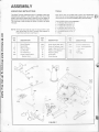
ASSEMBLY
UNPACKING INSTRUCTIONS
TOOLS
The Snow Thrower Attachment and all necessary parts and
hardware are packed in one carton. Open the top of the
carton, and remove small parts. Carefully cut the length of
each corner of the carton and fold down the sides of the box.
This provides a clean surface on which to mount the Snow
Thrower.
W ith some tools you already own, plus a few inexpensive
items that can be purchased at your Sears store, set-up and
maintenance can be accomplished quickly and accurately.
another free manual from www.searstractormanuals.com
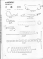
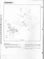
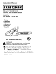
NOTE: Terms left and right as used in manual refer to left
and rights sides of Snow Thrower when seated on
Tractor facing forward , see Figure 1.
REF.
NO.
REF
NO.
DESCRIPTION
1
4
6A
Mount Bracket
Mount Rod
Rear Lift Ass ' y.
Lift Push Bar
Lift Tube Ass ' y.
Chute Crank Support
Bracket Ass 'y.
7
9A
33A
TOOLS REQUI RED FOR ASSEMBLY
1. 5/ 16 Open End Wrench (1)
2. 3/ 8 Ooen Erd Wrer"lch (1)
3. 1/ 2 Open e"O Vlrench (2)
4. 9/1 6 Open Eno 'Nrench (2)
5. 15/1 600€... E.,c J'. rench (2)
6. Flat Blade Sc•e"' ::Jr . e• (1 J
7. Pliers
DESCRIPTION
RE F.
.,0
Chute Crank Rod Ass·y.
Chute & Deflector Ass 'y.
Auger, Head & Lift Ass 'y
Pedal & Lock Bracket
Retaining Wire
Clutch Rod
Clutch Spring
36A .
51 A
70A
81
82
83
84
~·~.,
51 A
~-.!.
-
DESCRIPTION
c _:en & Brake Ass'y.
: _·:- ::J1sengagement
.:.·- ~.SS
i·
Left
Side
Yf _83
-·--
"()
~ 84
Right
Side
r
;
P.B .
~·
J
6A
FIGURE 1
4
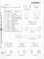
ASSEMBLY
PARTS BAG
~
®
STEP 1
Open Parts Bag and identify contents as shown on pages 5
and 6.
(115) X-1535
Flat Washer - 1
(112) X-1070
another free manual from www.searstractormanuals.com
318 Split Lock Washer - 1
REF.
NO.
PART
NU MBER
88
8
100
12
104
2
109
31
99
32
3
54
5
52
53
80
105
106
103
50
79
112
115
107
X-1036
X-1048
X-1182
X-1382
X-1439
X-1147
L-172
L-59
L-303
X-1107
X-1199
4-10900
X-1229
X-1242
L-242B
L-298
14-A1423
4-10227
14-A1403
14-A1011
14-A1109
X-1070
X-1535
14-A1410
a
T
y
DESC RIPTION
1
4
3
1
1
10
1
2
3
4
10
4
6
8
8
3
1
1
1
2
2
1
1
1
7/16 Flat Washer
3,4 • Flat Washer
1.4-20 x 11.4 Hex Head Cap Screw
Clevis Pin
%-16 x 41/2 Hex Head Cap Screw
%-16 x 1 Hex Head Cap Screw
1 I 4-20 X 3/4 Hex Head Cap Screw
5/16-18 x 3.4 Hex Head Cap Screw
1.4-20 Hex Lock Nut
5/16-18 Hex Lock Nut
%-16 Hex Lock Nut
Chute Ring Clamp
Hair Pin
#1 0-24 x 1 Hex Mach. Screw
#10-24 Hex "Kep• Nut
Hair Pin
Belt Guide
Spring
Spring-Brake
Pull Chain
Spring-Assist
3/8 Split Lock Wasrer
Flat Washer
Spring Return Brac-:e:
(88) X-1036
7116 Flat Washer -1
(8) X-1048
314 Flat Washer- 4
.
D
(100) X-1182
1/4 -20 x 1114 Hex Head Cap Screw- 3
0
(12} X-1382
Clevis Pin - 1
~"--'--11 ~
dl l_
_ _ __
(104)X-1439
318-16 x 4 1/z Hex Head Cap Screw- 1
(2) X-1147
318-16 x 1 Hex Head Cap Screw -10
@
(99) L-303
1/4-20 Hex Lock Nut- 3
~
(109) L-172
1/4-20 X 3/4 Hex Head Cap Screw- 1
g
~
(31) L-59
5 /1 6-18 x 3.4 Hex Head Cap Screw- 2
©
(32) X-1107
5116-1 8 Hex Lock Nut - 4
(3)X-1199
318 -16 Hex Lock Nut- 10
5
ASSEMBLY
PARTS BAG (Cont.)
~
(53) L-242B
#110-24 Hex wKep • Nut- 8
(52) X-1242
1110-24 x 1" Hex Mach . Screw- 8
another free manual from www.searstractormanuals.com
(54) A-10900
Chute Ring Clamp - 4
(5) X-12 29
Hair Pin- 6
(107 •4-A1 4•0
Spnng Reh.. r., B ..acl(et -1
~I
(80) L-298
Hair Pin- 3
{105) 14-A1 423
Belt Guide- 1
{106) 4-10227
Spring- 1
(1 03) 14-A1403
Spring-Brake- 1
(50) 14-A1011
Pull Chain- 2
{79) 14-A1109
Spring Assist - 2
6
ASSEMBLY
A
CAUTION
A
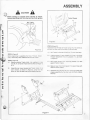
Before starting to assemble Snow Thrower to Tractor,
remove spark plug wire from plug and key from ignition.
Tractor Chassis
another free manual from www.searstractormanuals.com
Ref. Tractor
Item (14 & 23)
3
Ftgure 3
STEP 4 (Figure 3)
Assemble Snow Thrower to Tractor us ng. ~our hex bolts (2),
and four hex lock nuts (3) furnished m the parts bag.
Figure 2
A.) Roll Tractor to the rear of the Snow - nrower head assy.
ST EP 2 (Figure 2)
Before beg inning to assemble the Snow Thrower Attac~>
ment, remove any other Attachments from the - ·actor
B.)
STEP 3 (Figure 2)
A .) Remove existing Tractor bolts, lock Nashers & nuts
Item 46, 47, & 48, See Tractor Owners Marua. Pa;es 12
& 13.
B.)
Assemble rear mount bracket and Tractor re~s · .! &
23) to Tractor, as shown In Figure 2 us .,, 'c...• r ex
bolts, (2), four hex lock nuts (3), and tighte'l sec.. •e y
Ali gning holes in Tractor chass•s w•tn those In the Snow
T hrower Attachment mounting brQCI(et (1 1), as shown
in Figure 3).
C. ) Roll Tractor forward until mounting bracket (11) rests
agai nst Tractor chass.s
D.) Raise or lower mount ng bracket (11) to align holes with
those in tractor chass s.
E. )
Assemble four hex bo ts 12 thru mounting bracket and
chassis, assemble 'our hex locrt nuts (3) to bolts, tighten
securely .
Figure 4
7
IL
ASSEMBLY
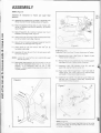
STEP 5 (Figure 4)
Assemble lift mechanism to Tractor and auger head
assembly.
A.) Assemble four washers (8), furn ished in parts bag , and
lift bar (7) onto lift lever rod (6) as shown in Figure 4.
B.) Place lift assembly/lift bar (6 & 7) under Tractor w ith
lift bar (7) towards front and lift assembly (6) towards
rear of Tractor.
another free manual from www.searstractormanuals.com
C.) Raise lift assembly (6), locating it between rear mount
brackets (1) and align holes, Figure 4.
D.) Insert mount rod (4) through holes and secure w ith hair
pin (5) furnished in parts bag, Figure 4.
E.) Raise lift bar (7) locating it between bracket of front lift
mechanism (14) and align holes . Figure 4.
F .) Insert clevis pin (12) and secure with hair pin (5)
furnished in parts bag.
G.) Assemble lift tube (9) over lift arm (6) and secure with
hair pin (5) Figure 5.
NOTE: Location it1 is used without cab Location #2 is used
with cab (Figure 5).
H.) Raise auger head assembly by PtJ r.g back on the lift
tube (9), lift mechanism should oc n the up lock
position • .If lift mechanism does not OCI( in lock
podiyion•, remove washer (8) as required to obtain the
•up lock position.~
STEP 6 (FigtJ•e c
Assemble V-be t •·::- ::-:• ---;: ... :• ~::achment to Tractor.
A .) Remove pu e1 ::::::-.:· ~
Tractor Owners '!a--~
~
1~
;_•e
Page 6 of your
B. ) Remove hex bo ~a-:: 'A~-=- se~-- -; ruft'er support
(See Page 18ofya ... ·-·ac·-;· :.-,.. s :Vanua ).
C.) Assemble V-belt ·r,e :.::-...:-:- : .. ey 121) and belt
guard (18), placmg '/-::-: • :- :_ :' 2"
D.) Place V-belt (108 ·-·:.;- - : : - • gnt hand side of
Tractor grille. oo: -=~ "J: a·:-·o engine pulley
et
and locate in first ;•:>::"O: :' :-; -:
·
Figure 5
I
=-
E .) Assemble Joel( ... as-:· · ·: :._-:: :.::; gutde (105) onto
hex bolt (1~ '-·- !·:-: · :::::.~ 3ag replaci ng hex
boltremoveo rS::: : =-::.:
Figure 7
...::
_1 ..
-
-......
"
5
8
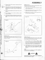
STEP 7 (F gure 7
Assemble I It assis<s a"'C a ..,e• ·saa stab zer springs using
two pull charns ~ r~t c !Or nvs "'"9 a"'d two hair pins (5),
furnished in Pans Sa;
ASSEMBLY
A.) Thread pull chain (50), one each, through eye bolt and
bracket, Figure 7.
B.) Hook one end of each spring (79) through hole In front
lift mechanism (14) or chain link on front bracket (11).
Hook other end of spring to ends of roll chains. (50),
Figure 7.
C.) Raise auger head assembly with lift tube to the •up lock
position. •
STEP 9 (Figure 9)
Assemble chute control rod (37) to universal (38) on control
rod (40) and secure with hair pin (80).
A.) Place straight end of chute control rod (37) thru chute
control rod support (33).
B.) Install chute control rod (37) into universal (38) and
align hole in rod with hole in universal.
C .) Secure control rod (37) to universal (38) with hair
another free manual from www.searstractormanuals.com
D.) Pull on toggle end of pull chain, exerting a slight
pressure on spring.
E.) Hold tension on spring by inserting hair pin (5) through
chain just above bracket & eye bolt; repeat for opposite
chain.
pin (80) furnished in Parts Bag.
Figure 10
·~
r
Figure 8
~ 51A
52
(
_____,
STEP 8 (Figure 8)
Assembly crank rod support (33) to Tractor ~; s ..,!; _ ~ ... o rex
bolts (31) and two hex lock nuts (32), furn ished in Pa-: 3ag.
as shown In Figure).
Figure 9
37
t
40
/ (1
~)
--~
~
STEP 10 (Figure 10)
Assemble discharge chute (51A) to Snow Thrower Head
Assy. (70A) using eight slotted hex head screws (52), eight
hex nuts (53) and four chute ring clamps (54).
A ) With discharge chute opening forward, attach
o sc"arge ch.Jte 51A 011to tne Snow Thrower Head
Assy JOA - he discharge chute (51 A ) must sit on the
SnoN - hrower Head Assy. (70A ) w ith teeth of the chute
crank gear (40) in holes in ring of discharge chute.
B .) Attach discharge chute (51A) to Snow Thrower Head
Assy. (70A) w ith four chute ring clamps (54), eight
slotted hex head screws (52), and eight hex nuts (53),
Figure 10.
NOTE:
A small amount of lubricate on ring before assembly of
discharge chute will ease assembly.
A
CAUTION
A
Chute Guard (55) must be In place to prevent anyone from
reaching Into chute (Ref. Page 21).
9
ASSEMBLY
another free manual from www.searstractormanuals.com
109
99
J.
, ,
/
I
/
./
'3
_J
Figure 11
STEP 11 (Figure 11)
Assemble power pack assy. (97A) to Tractor using: Three
hex bolts (2 & 109) and three hex lock nuts (3 & 99).
A.) Remove existing Tractor bolt , lock washer aJ'O Items (34, 35 & 36), See Tractor Owner's Manua Pa;es
14 & 15.
10
~=
.-::.: · ·:.: : - ="" :- _-:-
·-- -
- =-
-= .....
:
=~
""--= :>etween brake
ASSEMBLY
~~
another free manual from www.searstractormanuals.com
100
,
103
-------~
-~- - - - - -
1
1
I
I
I
I
88
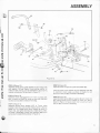
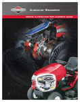
STEP 12 (Figure 12)
Assemble brake spring (103) between clutch linkage (85)
with washer (115) see Figure 12 and spring retainer on
brake arm (95). Spring must be assembled to top of spring
retainer on brake arm (95) as shown in Figure 12.
STEP 13 (Figure 12)
Assemble clutch disengagement arm (101) to power pack
assy. , as shown in Figure 12, using two hex bolts (100) and
two hex lock nuts (99) furnished in Parts Bag .
STEP 14 (Figure 12)
Assemble spring return bracket (107) to Tractor using
existing Tractor bolt, Item 34, See Tractor Owner's Manual
Pages 12 & 13. Locate spring return bracket as shown in
Figure (12), and tighten bolt securely. Attach spring (106),
furnished in Parts Bag, to clutch lock weldment (96) and to
spring return bracket (107) as shown In Figure 12.
ST EP 15 (Figure 12)
Assemble clutch rod (83) into pedal lock bracket (81 ).
Assemble pedal & lock bracket (81) and retaining wire (82)
to attachment clutch pedal, as shown in Figure 12, and
secure with hair pin (80), furnished in Parts Bag.
STEP 16 (Figure 12)
Assemble clutch spring (89) and washer (88) onto clutch rod
(83), placing clutch rod thru bracket on clutch arm (90) as
shown in Figure 12. Secure clutch rod to clutch arm with
hair pin (80) , furnished in Parts Bag.
11
ADJUSTMENT
All V-belts can stretch, most stretch occurs in first four
hours of use. Check V-belt adjustment after 1/2 hr. use, 1
hr. use, and every hour thru fourth hour of use. After tour
hours use, check the V-belt adjustment prior to each time
Snow Thrower is operated.
CAUTION
another free manual from www.searstractormanuals.com
Failure to maintain proper belt tension could result In
premature V-belt failure.
~
)c c t//
- - -I
~
C//
=: . . ""S .. 5
A
CAUTIO~
A
No adjustment s to ' ~ : ::e • ~= should be made
w ithout shutting off the -a::- ::r :-; "e and removing the
spark plug wire f rom soa~• :: -;
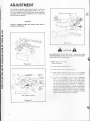
STEP 17 (Figure 14 15 &. ::
V- Belt Adjustmertt
Figure 13
A .) T ractor eng rre
~
B .) Snow Throy,.er -
Incorrect
_..--',Belt
/
' Tension
' LOOSE
Correct
Belt
) Tension
_s· =-=!-_· :-•
.!'
C.) W hen Tractc• :--~(In) poslt 1o~ :;:··=c·
D.) To ad1us:
-=-· · .-=- ; ::• s n the engaged
=-= ·=·.! =- H -~..,.n by Figure 14.
-?-~:-
=-· : -=·::;~: ::s · ::·
· :·
Belt Tension Indicator
Figure 14
~·:
-:.; - ·actor attachment
= ;t..re 20) remove
: •--- ;..·:·:·: - ':" ;-·= ·5 Slide lift arm
(15 :
a·:·:-:- - _- - =..- =~,ter-clockw ise to
nc•ea..!e • -:-: • =-~
a·: : :c· .. s.e to decrease Voe • e':! :· : : .r :c · ~..: ::::~, :o keep unit
s:.:.·: • ·- - -:.:-:.- :::: a:e - :.-s a.,d secure with
·a·:-! .•::-.; - -.:c--=r ~-=c.--:· ·: _;;;n arm lever to
e-.;z;:c • =~
a-: ::.-:;c.< : _ :~ arm (90) for
:·::-=~ se- ·; =-::::~: :: ·~ = ·:cessary to obtain
lever :o
hair c-
-::·
=-= ::· ;-::.-:
another free manual from www.searstractormanuals.com
ADJUSTMENT
----- -~
~------
Tractor Attachmen: C
1
-~:;.- _e.e~
90
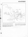
Figure 16
Information on Snow Thrower clutch & brake ass 1 ;: g.-re
(16), for your Sears No. 260250 Snow Thrower Attacr~e-:
When Tractor attachment clutch lever Is moved 1tc ·-e
engaged (in) position, clutch rod (83) will rotate clutch a.-~
(90) upward against brake arm (95) removing it from V-oe t
(108) while engaging clutch idler Into V-belt (108).
When Tractor attachment clutch lever Is moved Into
disengaged (out) position . the clutch rod (83) will rotate
clutch arm (90) downward allo"" ng spring to roll brake arm
95 0'110 V-be: 108 ,.,. ... eo seogagmg clutch idler from Vtle •
·ca
13
OPERATION
DISCHARGE CHUTE
CONTROL ROD
another free manual from www.searstractormanuals.com
[
D ISCHARGE CHUTE
- - AND DEFLECTOR
.. .....
Au GER & H EAD
ASSEMBLY
I
Figure 17
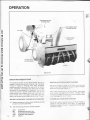
OPERATING INSTRUCTIONS
The operating capacity of your Snow Thrower can be increased by careful observance of operating rules. Your Snow
Thrower is capable of handling heavy snow conditions.
However giving the equipment the opportunity to function
within reasonable requirements w ill assure you of longer
equipment life, less possibili ty of damage to the unit and
require less power to operate. Make certain that you are
totally familiar with all aspects of both the Tractor and your
Snow Thrower prior to its usage. Listed below are suggestions to Improve the performance of your Snow Thrower
STARTING AND s-o ::~ .~ S'o OW ~ROW ER
BEFORE PLACING SNOW THROWER INTO OPERATION
TO RAISE AND LOWER SNOW THROWER
A .) Check all screws and nuts for proper tightness and that
all parts are properly assembled.
The lift arm used to rase and o ... e• ;-e Snow Thrower is
located on the right s1de of tre - ractor. To raise Snow
Thrower pull back on lift ever. - o o.... er Snow Thrower push
forward on lift lever.
B.) Test the following contro ls for smooth operation.
(47A)
(28)
(100)
(72A)
14
(45)
Clutch lever
Discharge chute control rod
Discharge chute and deflector
Auger and Head Assembly
Lift arm
The Snow - -·:111:· s :· .:- : a .-oe; drive from the
Tractor e-;; -;:a-:: s ::::"a·;c::: -·::_;- :"e Snow Thrower
attach"'"e-:: _;::~ e.e--- =;_ ....-:·Start T·ac;o• engine a"lc •-" at -a- :-·or..e. Push clutch
e-ver 'orv.a•c to engage S"'~a .. - --::,.,e•. "!crease Tractor
:•--o;; e to ·u speed - o s·::: s-:: ... -- -::. ... er operation push
:: :.:•::" d se,gagemem e.e· ·:~... a·.:
OPERATION
A
CAUTION
A
another free manual from www.searstractormanuals.com
If Snow Thrower auger does not stop within 5 seconds after
the Tractor attachment clutch lever has been moved to the
disengaged (braked) position check unit for adjustments or
worn parts and repair before operating.
The V-belt, used In this Snow Thrower attachment is of
special construction, designed for use with the V-belt
clutch/brake system. For continued satisfactory performance use only replacement belts supplied by the
manufacturer.
The use of Improper V-belts on the V-belt clutch/brake
could cause early failure of the replacement V-belt. V-belts
not designed for this type of drive, while similar in appearance, may have an exterior surface of cord construction that
will not perform satisfactorily In a V-belt clutch/brake
system and could In some cases cause a malfunction in the
operation of the machine.
Do not operate this Snow Thrower unless it is operating
properly, as outlined In your owner's manual.
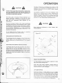
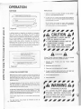
The Snow Thrower has a discharge chute rotation of 270
degrees and Is controlled by the discharge chute rod. The
d ischarge chute stop bolt will prohibit rotation beyond
points H. Figure 18.
The deflector mounted on top of the discharge chute
determines the distance snow is thrown. Moving top of
deflector down decreases distance of throw, while raising
deflector increases it. Adjustment of the deflector can not be
made from the riding position. Disengage the PTO clutch
and shut oft Tractor eng ine before making adjustment.
A
CAUTION
A
When making any adjustment to Snow Thrower, shut
Tractor engine oft.
Figure 19
DISCHARGE CHUTE CONTROL ROD
The discharge chute rod Is located on the le'l hano s de of
Tractor, Figure 17 turn rod clockwise to direct s11cr,o, :c t'le
left hand side and turn counterclockwise 'o• ; ~e o;::oos ;e
effect.
79
"-..
DISCHARGE CHUTE DRIVE TUBE ADJUSTMEW
If d ischarge chute will not hold its position ar-c :e'1ds to
rotate, adjust lock nut (34) on discharge chute •oc eJe bo•t.
Tighten lock nut 1/8 turn and check rotat or o' dr.ve
sprocket by turning discharge chute crank. A small amount
of resistance should be encountered. Do not over ~·ghten.
Tighten until chute holds Its position. (Refer to Attacl1ment
Parts Listing)
..
7
HEAD STABILIZER SPRING
The head stabilizer spring (79) helps to stabilize the head
assy. while Tractor is being driven.
With V-belt (108) properly adjusted , increase tension on
spring to eliminate "V-belt creep• while Tractor Is being
driven with Snow Thrower disengaged.
LIFT ASSIST SPRING
Figure 18
With Snow Thrower In raised position pull up on toggle
chain and remove hair pin. Allow several links In chain to
pass down through the hole in mounting bracket and replace
pin just above bracket. To decrease scraping action when
Snow Thrower Is used on rough surfaces, increase tension
on lift spring by removing hair pin and pulling several links
up through hole In mounting bracket and replacing pin.
15
OPERATION
OPERATION
The s~:::.. ~...o ... er controls are conveniently located at the
opera::· s =~ O'l on the Tractor. By engaging the auger
clutcr s-: s :~•own through the discharge chute by the
motte ... :· ·-: ~wger . Turning the discharge chute crank
directs s-:.- : sc...arge and the angle of the deflector
con tro s ·-:: s·:t-::e snow is thrown .
·
Disengaged
OUT
.:-....
r.....
--
......
....,
I
)
L---.
I
I
\
I
I
r\- . . : .....
1
another free manual from www.searstractormanuals.com
I
'r-----,
'
t :,41,
t-- ~
L
Snow re'""c. a ::::-: : :-s vary so greatly from the fi rst light
fluffy sno .. ·a ·: ; ·;z-;y snow that operating instructions
must be 'e•: : ·: ' · ·-e snow removal encountered. The
operator rr -!' a:.a= ·-: - ·actor and Snow Thrower to depth
of snow, "' -: : -~ :-s. temperature and surface
conditions
_j
I
I
'
L,--,-""J
,
,
I
I
OPERATING
S?~=::;
I
The auger soeec ~ : :c- , •e a:ed to engine speed . For
maximum s":;;., ·:-- ~ a·c d scharge maintain high
engine R.P.tv'
s advisable to operate the
Tractor at as o ... ; -=-- -~ s::-ec ':>r safe and efficient snow
removal.
I
-----a ·
'.
Bracket
DEEP OR DR IFTED S~C 'r't
Figure 20
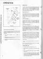
LOCK LEVER PLATE ADJUSTMENT
The lock lever adjustment plate (98) locks - 'EC4:l!" attachment lever into engaged (in) postion. Lock e.a· a::, ..slment
plate (98) must engage pedal & lock brac~e ; :· :.1 3 •s·
(Figure 20).
A.) Move Tractor attachment lever ·c
position.
8 .) Check overlap of lock lever adjustmen;:::
overlap of 3/16Nplus or minus 1 16
:-;~;=c
a ~= ::::: -·
C.) Loosen hex bolt (109) adjust as requ rec a-.::
securely.
(in)
.- ...g
-: ~ ;;~:e..,
In deep, drifted, orca_- "'3: s-:.. : "' oe necessary to use
full throttle and as C'A ~ .:..-: s:~ Drive the auger into
the snow, disengage-.......~-=-~- aro allow auger to clear
the snow. Repeat th.s - ; -x _-: a ;;ath Is cleared. On the
second pass overlap t-a • -r :-J _;;:- to allow the auger to
handle the snow wltho~: "?":~3:: _:r:n ng and declutchlng
of the tractor.
In extremely deep s-:;.. ~~ -- -: ... e• 'rom ground and
drive ahead Into sr>Oit ·: ·:- :--a ·:::: ayes first, keeping
Tractor out of snow :;a_-. :.C - :· :-;ar Tractor Into snow
bank where snow !'as - ::· :9i!- ·:-:Ned to ground level.
Disengage Tractor c
a-: a :" - "',ower to clear the
snow. Reverse Tract:::• .:..-:
--·ower to the ground .
Drive Tractor aheao a...· : ·;:ec· :·xess to r emove balance
of snow . Working " ~- ·e::-=z-:o: ::.asses 110 and out of drifts
will eventually mo.a
:e::-es· ::' s1ow piles.
_,=.-
=--=·
:-.=- -:
TIRE CHAINS
The use of t1re :::-.:.. -~ s ·acc- -e-oeo 'or exira traction at
all times.
Rear hitch-plate weights are a sc a.a a:: e from your Sears
Store If added traction IS reQ\J rec .
OPERATING TIPS
1. Whenever possible dtscharge S"! O"' cown wind.
2. Do not attempt to remove Ice or hard packed frozen
snow.
3. Always overlap each pass sl ghtly to assure complete
snow removal.
16
4. A frozen or stuck auger must be broken loose or thawed
w ith care. W hen attempting to loosen auger if frozen or
jammed, shut off Tractor engine and remove spark plug
w ires. Never attempt to clear Snow Thrower at any time
with Tractor engine running.
OPERATION
SKID SHOE ADJUSTMENT
AUGER CHAIN ADJUSTMENT (Figure 22)
The skid shoe mounted on each side of the auger housing
adjusts the distance the scraper blade is raised above the
plowing surface. When removing snow from an uneven
surface or a gravel driveway, it is advisable to keep the
scraper blade as high above the surface as possible to
prevent possible damage to the auger and to help prevent
stones from being thrown with snow. On blacktop or
concrete, keep the scraper blade as close to the surface as
possible. The Snow Thrower is shipped from the factory
with skid shoe flanges mounted to the side of t he housing.
After first two hours of operation check auger drive chain for
adjustment. It is important to maintain proper chain
adj ustment to obtain maximum chain lite. Excessive slack In
auger drive chain due to normal chain stretch can be
removed by adjustment.
To tighten auger drive chain proceed as follows:
A.) Shut off Tractor and remove ignition key.
another free manual from www.searstractormanuals.com
B.) Remove spark plug wire from spark plug.
TO ADJUST SKID SHOES (Figure 21)
Raise the Snow Thrower off the ground and place a block
under each end of the scraper blade. loosen the nuts
securing skid shoes to the auger housing (70). Move the skid
shoes (68) to the desired position and retighten nuts. Adjust
both skid shoes to the same height to keep the scraper blade
level.
C.) Remove cover (30) loosen Inside mounting nuts (27)
two or three complete turns.
0 .) Tighten outside adjusting nuts (27) to tighten chain.
(A lways tighten both outer adjusting nuts (27) an equal
number of turns). A correctly adjusted chain will have a
slfght amount of slack (1/4 to 3/8 inch).
SKID SHOES
E.) Retighten inside mounting nuts (27) to secure chain
adjustment and replace cover (30).
Both skid shoes are subject to wear and are designed to easy
replacement. Replace before wear is excessive to prevent
damage to the auger housing.
F.) Replace spark plug wire and resume snow removal.
A
cAUTION
A
Do not lubricate when the Snow Thrower Is operating.
Flgure21
Figure 22
AUGER DRIVE CHAIN
Periodically check auger drive chain to insure that it is
properly adjusted. It is important to maintain proper chain
adjustment to obtain maximum chain life. Excessive slack in
auger drive chain due to normal chain stretch can b~
removed by adjusting chain tightening adjusting nuts.
17
OPERATION
PREPARATION
METHODS
/
SNOW
---------
-----------------
1. Check th e Tractor and Snow Thrower to make certain
both are in good operating condition.
::>,.
RE MOVED TO EITHER SIDE
2. Fill gas tank out of doors and advoid spilling gasoline
over eng u~e Do not fill tank with gasoline while smoking
or whl e eng ne is running .
..
Do not remove any guards or covers while operating
Tractor a"'O S"o"" Thrower or make any adjustments
wh e d s .....c.-:ed !rom the driving position.
FINISH
another free manual from www.searstractormanuals.com
Figure 23
,~~~~~~
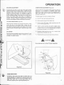
A definite pattern of operating is required to thoroughly
clean the snow area. This pattern will avoid a second
removal of snow and avoid throwing snow In unwanted
places. Where It is possible to throw snow to right and left,
as on a long driveway, it Is advantageous to start In the
middle. Work from one end to the opposite end throwing
snow to both sides without changing the direction of
discharge chute. If snow can only be thrown to one side of
the driveway or sidewalk, start on the opposite side. At the
end of each succeeding pass, rotate the chute 180 degrees to
maintain direction of snow thew into same area.
~ ~p £~~!!2~ND~ ~
~ • KEEP All SHIELDS IN PLACE.
,.
,. • IF UNIT BECO~ ClOGGED, SHUT OFF ~
~
ENGINE BERJR.E CLEANING.
,. • KEEP HANDS FEET, AND CLOTHING
AWAY FRO POWER-ORfVEN PARTS. ~
·~~~~~~
<
SNOW PIL ED ON LEr SIDE
START ON LEFT SIDE
(
ROTATEO CHUT' ' "
If Snow Thrower becorna :: -i'i-liC with snow or jammed
due to hitting an obstruc _- :;.r:JC:HC as follows:
1. Declutch Snow
immediately.
n: .._ _
-"'
stop Tractor engine
2.
Fig ure 24
3. Clear snow lro- -
Before the f irst snowfall, the area in which snow removal is
to take place should be cleared of all stones, sticks and the
like which might be picked up by the auger. All obstacles
should be marked to protect the Tractor and auger from
possible collision.
To become familiar with the controls, operate tne -·ac:o•
and Snow Thrower In a clear area before rerno.r "g s-o-~
The more familiar you become with the Snow Thro~e· • .,e
better results you will have In its use.
A light coat of wax applied to the inside surface of t he auger
housing will prevent snow and Ice from sticking to it. The
Inside of the discharge chute and deflector should be waxed
several times during the snow removal season.
Allow ample engine warm up time before starting snow
removal.
18
For best results, snow should be removed as soon as
possible after it falls.
_ :>OStruetlon and repair any
4.
OPERATING SUGGESTIONS
::lEb:-e etm!Jnuing.
6. Res..-• :!)UI'
•.
..
A WARNING A~
,~~~"""''
SPINNING BLADES
.IIIII
~ TO AVOID INJURY SHUT OFF , .
"' ENGINE BEFORE SERVICING ,
ADJUSTING OR UNCLOGGING ~
~ SNOW THROWER UNIT.
,.
-
.,~~~~~~
MAINTENANCE
another free manual from www.searstractormanuals.com
60
Figure 25
A
CAUTION
A
Do not lubricate when the Snow Thrower is operating .
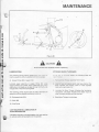
LUBRICATION
STORING SNOW THROW ER
The following fittings require grease every ·::_ ~ -:- ~ - •
machine operation with any standard comme':: a ;·:c..se
.:. ~ ~ ~e
~ ;:.:::: -
=:-:..,: S:1o"' Thrower assembly from Tractor.
A) Grease fittings (60) on auger shaft.
Lubricate auger assembly at grease filling 160 ~.os -g
regular pressure gun grease. Apply grease with gu, t. ~t a
sllgh{ amount of grease can be seen coming from boll"! ends
of auger shaft. Wipe off surplus grease.
e-:: : · · -e s-:::ti season the following steps are
-:-==-=
2
Wash off any salt deposit which may have dried on the
Snow Thrower and housing. Paint or cover exposed
metal with a light coat of oil.
The following points require lube oil every five hours of
operation with any standard commercial motor oil.
3. Lubricate the Snow Thrower following the lubricating
instructions. The Snow Thrower drive chain must be
oiled thoroughly to stop rust from forming .
B) Discharge chute (51 A)
4. Store Snow Thrower in a dry place.
C) Chain (63)
0) Pivot Points
LIGHT MACHINE OIL LUBRICATION OF
AUGER BEARINGS (58)
Lubricate at the start of the snow season with light machine
oil, and also when storing machine for the summer.
19
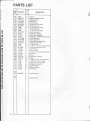
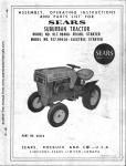
PARTS LIST
another free manual from www.searstractormanuals.com
KEY
NO.
-
20
1
2
3
4
5
6
7
8
9
10
11
12
13
14
15
16
17
18
19
20
21
22
23
24
25
26
27
28
29
30
31
32
33
34
35
36
37
38
39
40
41
42
43
44
45
46
47
48
49
50
51
52
53
54
55
56
57
58
59
60
61
62
63
a
PART NO.
T
y
14-B1173
2
X-1147
10
X1199
16
14-A11 54
1
X-1229
13
14A-D1203
1
14-B1204
1
X-1048
8
14-C1408
1
16-3080B
1
14A-C1161
1
X-1382
1
14·A1155
1
14A-C1106
1
14A-A1067
2
14A-B1252
2
X-A1499
4
14A-C1259
1
X-1016
6
X-1003
2
14-C1074
1
X-1389
1
14-C1166
1
4-10840
2
14A-B1006
1
14-A1049
1
X-1341
2
X-1532
2
X-1397
1
14-C-11 70
1
L-59
7
X-1107
9
14-B1100
1
L-60
6
X-1235
3
14-B1139-2
1
14-A1317
1
14-A1296
1
X-1369
1
14A-A1089-2 1
4-10709
1
4-10702
1
L-99
5
14-C1022
1
14A-B1180
2
X-1025
2
14-B1396
1
14-A1262
3
X-1395
2
14-A1011
2
14A-D1024
1
X-1242
8
L-242B
8
4-10900
4
14-C1386
1
X-1042
2
4-11109-2
1
14-A1414
2
14A-D1111
1
X-1492
2
14A-B1041-2 1
14-B1260
1
14-A1191
1
KEY
NO .
DESCRIPTON
Mtg. Brkt.-Rear Tractor
3/8-16X1"H.H.Cs.
3/8-16 Hex Lock Nut
Mtg. Rod- -Rear
Hair Pln
Rear Lift Ass ' y
Lift Push Bar
3 / 41. D. X 11/4 0. D. Flat Washer
Lift- Tube
Hand Grip
Tractor Pivot Mtg. Brkt. Assy.
Clevis Pin
Mtg. Rod- Front
Front Lift Pivot Mech.
Top Front Lift Arm Assy.
Top Adj. Arm Weld
Clevis Pin
Belt Guard Assy.
#1 0-24 X 3/8 Self Tap Screw
" E " Ring (3 /4 D. Shaft)
5" 0 . D Pulley
Sq. Key (3 /16 Sq .X 5 / 8)
Jack Shaft
Bal Bear ng
Jack Sha't - ube W eld
Sproc><et 11 T
1-iex Jam r-.~ :
Flat Washer
Sq. Key (3/ 16Sq X7/ 8)
Jackshaft Access Cover
3/ 16-18 X 3/4 H. H . C. S.
3/16-18 Hex Lock Nut
Chute Crank Support Bracket
5/16-18 Hex Nut
5/16-18 Eye Bolt
Chute Crank Rod
Chute Crank Hand Grip
Chute Crank Universal
Roll Pin (1 / 8 Diam. X 3/4 0
Chute Control Rod Ass 'y.
Cup Washer
Chute Control Spring
5/16 Flat Washer
Chain Guard
Chute Adjustment Lever
5 /1 6 Split Ring Lock Washer
Chute Defl ector
Warn ng Decal
-~ ... -...7 16 I. D Ex: - oot,... . oc .... e.:.
;
Pull Cham - L 't
Chute
Jf1Q-24 X 1 2 N'ac" ~e Sc·e~o
#1Q-24 Hex " Kep • ~ ut
Chute Ring Clarno
Chute Guard
5 /1 6-18 X 5 / 8 Carriage Bolt
Auger Shaft
Auger Bushing
Auger
Grease Zerk
Swing Baffle
Decal - Sears
Chain - #40 (97 Pitches)
64
65
66
67
68
69
70
71
72
73
74
75
76
77
78
79
a
PART NO.
14-A1276
L-127
X-102t
L-6~
14-C1C29
X- 1QO.!
14A·D• 275
X-1279
L-64A
14-B1UC
14-C1193
X-1353
14-A 126'
1~-C'2''2
'4-B" • J•
14-Ai · CS
T
y
2
2
6
12
2
2
1
2
2
.
2
.
.
.
-2
DESCRIPTION
Bumper Stops
5/ 16-18X11/2H.H.C.S.
3 / 8-16X 3/4 H. H. C. S.
3 / 8 I. D. Flat Washer
Skid
Ro Pln (11 4 Diam. X 11/4)
A uger Housing Ass'y.
1 2-13 X21 / 4H.H . C.S.
• 2 D. Flat Washer
d er Sprocket- 18 Tooth
c er Soroket Plate
• 2-• 3 1-iex Lock Nu t
Ca .. • on Decal
G· ::... ~c: Soeed Decal
'.'xe Ser•al Number Plate
S: · ~~;- '- 't Assist
.
..
•
39
~/
38
45
(-~ {~
80
35
another free manual from www.searstractormanuals.com
~~~34
"'
49---4-,~ ,
~42
'
.
.......
48
32~c .. -32~ " ·~ ~:
. ~
~-'
0
1
.
<.. - 48 -~ ~
s•_... .r.
I ,
"'
t1
""
ta -l-' 1":>. \ ' ·, · -·• ' / "
' 'lA
~--
I
31
A
< ..1.~,~- ·7
•, '•
'
18
32
"'T..,
•• 1
-
10 ' { /
'JO
9
4
'~~
) 5
I (./
~
(l i . .
1
I
Y;'
11 0
l Oll
I
(
~)
•I
u
Ll
t· •
4
'
2
29
3
ll!Ji'D.V
..
a' '<:?@,A
3
J
'-
.....
,
.
28
' '
22
~2·
~
5
~
13
L
f
79
~ ~
#;/"
A·~
, ,
~
,,
•
'
~/
'·
;·
•I
/J /
I
68
f"
rl
\
,
~
" '~·
19
\._
110
50
'
~63
/T~
l 32
/I
~., ~~ ' I !{J __)
il/
31 3
! ,u;
11
~ /'~ ~....,.. < ,£
. ••
"
\..
"fi-' .
...-.
~
_,sa
-1)....
""''';. !/r(.
\ '·, I,
~")
-~
48
"'-1'
','
.....,
•
'
/i.ll'
'·
\
I If~, -~
' I
.....
~
~27 ~
\o-27
~
3
!};;:--..- , \
. •.
ltu 1/.t •I •
/
'"'J:.• '(
~.~ :r·-~ ~,,,
5
6
~
~ 60
52-y
37
\
1\.)
'$- 43
--+51~55
~34
.....
'
~60
31
i
\
~
~ 43
~J
47
56 ~lss
'~~
(. / / < ~
40
I
30
.,.....67 66
.72
73
....
•
~~--~,lc~--\~ ~/'- ,
~
71
72
73
1
74
43
I
75
-a
)>
:::D
-1
en
-
r-
~
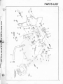
PARTS LIST
KEY
NO.
T
y
DESCRIPTION
97
98
99
100
101
102
103
104
105
106
107
108
109
110
111
112
113
114
115
L-298
14A-B1417
14-B141 3
14A-B1420
14-A1226
14A-A1407
19-A1400
L-269
X-1036
L-266
14A-B1097
X-1127
14-B1147
X-1208
14A-B1058
14A-B1 406
14A-D1215
14-A1422
L-303
X-1182
14-C1409
1-1527B
14-A1403
X-1439
14-A1423
4-10227
14-A1410
14-B1073
L-172
X-1132
L-223
X-1070
X-2036
14-1441
X-1535
2
1
1
1
1
1
1
6
1
1
1
1
1
1
1
1
1
1
3
2
1
1
1
1
1
1
1
1
2
6
1
1
1
1
Hair Pin
Pedal & Lock Brkt. Weld
Retaining Wire
Clutch Rod
Spring -Clutch
Clutch Pivot Arm Weld
Clutch Pivot Link
"E" Ring (3/8 D. Shaft)
7/16 Flat Washer
•p Ring (1/2 D. Shaft)
Clutch Arm Weld
3/8-24 Hex Lock Nut
Idler Pulley- Backside
3/8-24 X 21/4 Hex Head Cap Screw
Pivot Brake Weld
Clutch Lock Weld
Clutch/Brake Bracket Weld
Lock Lever Adj. Plate
1/4-20 Lock Nut
1/4-20 X 1 1/ 4 Hex Head Cap Screw
Clutch Disengagement Arm
Tube End Cap
Spring- Brake
3 8-16 X !.. • 2 Hex Head Cap Screw
Be I G~ CE
Spr ng
Spring Re1~ ·- a•ac<et
V-Belt
1/4-20X 2 !.. ""leX -eao Cap Screw
1/4 Ext. Toot'"' _x.- .·.asher
5/16-18X3 t..Ca..-a;eBot
3/8 Split Lock \1\as ..e•
3/8 Flat Washe•
Brake Arm Slee"e
Flat Washer
Not
Ills.
M14-8002
1
Owners Manual
1
Warranty Tag
80
81
82
83
84
85
86
87
88
another free manual from www.searstractormanuals.com
a
PART NO.
89
90
91
92
93
95
96
Not
Ills.
'
22
2
.'
another free manual from www.searstractormanuals.com
PARTS LIST
~
\
\
0,....
\
\
\
\
0
0>
I
Sears
MODEL NO.
another free manual from www.searstractormanuals.com
180.260250
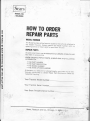
HOW TO ORDER
REPAIR PARTS
MODEL NUMBER
The Model Number will be found on a plate on the e{t s de attached to
the Header Housing. Always mention the Model umber when requesting service orr repair parts for your Snow Throv.e•
REPAIR PARTS
All parts Siea herem may be ordered from any SEARS. ROEBUCK AND
CO. retail or ca~a og store.
WHEN ORDE=! \G
INFORMATION.
•
•
•
•
THE
THE
THE
THE
~EPAIR
PARTS, ALWAYS GIVE THE
FO~OWING
PAR- \-.;','3ER
PART CESC~ PTION
MODE~ \...,','SEA
NAME o = '.'::=!CHANDISE
If the parts yo~ -e-e: a·e '10t stocked locally, your orde· .•. oe e ectronically trars ..... =~==
a Sears Repair Parts Distribut o- Ce- ~a· for
"expedited hare -~
:::
Your Tractors Mode
umber____________
Your Tractors Ser"al Number____________
Your Snow Throwers Ser al Number_______ __
Sears, Roebuck and Co., Chicago, Ill. 6068l uS ~