1
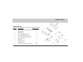
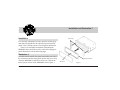
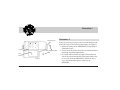
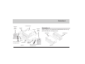
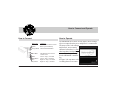
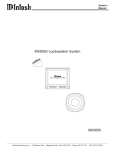
OWNERS MANUAL Power Output Meter MPM4000 McIntosh Laboratory, Inc. 2 Chambers Street Binghamton, New York 13903-2699 Phone: 607-723-3512 FAX: 607-724-0549 Thank You, Please Take A Moment Thank You For your decision to own this McIntosh MPM4000 Power Output Meter ranks you at the very top among discriminating music listeners. You now have The Best. The McIntosh dedication to Quality, is assurance that you will receive many years of enjoyment from this unit. Please take a short time to read the information in this manual. We want you to be as familiar as possible with all the features and functions of your new McIntosh MPM4000. This will ensure that you receive all the performance benefits this equipment can offer you, and that it will become a highly valued part of your Automotive entertainment system. 2 Please Take A Moment The serial number, purchase date and McIntosh dealer name are important to you for possible insurance claim or future service. The serial number is located on the rear panel of the equipment. The spaces below have been provided for you to record that information: Serial Number: Please Take A Moment cont, Customer Service Purchase Date: Dealer Name: Customer Service If at any time you have questions about your MPM4000 Power Output Meter, please contact: McIntosh Laboratory, Inc. 2 Chambers Street Binghamton, New York 13903 Phone: 607-723-3512 FAX: 607-724-0549 Copyright 1997 by McIntosh Laboratory, Inc. 3 Table of Contents Table of Contents Thank You .......................................................................... 2 Please Take a Moment ....................................................... 2 Customer Service ............................................................... 3 Table of Contents ............................................................... 4 Safety Instructions ............................................................. 5 Introduction ........................................................................ 8 Performance Features ........................................................ 8 Supplied Items ................................................................... 9 Installation ....................................................................... 10 Illustration 1 ..................................................................... 10 Illustration 2 ..................................................................... 11 Illustration 3 ..................................................................... 12 4 Illustration 4 ..................................................................... 13 How to Connect ............................................................... 14 How to Operate ................................................................ 14 Specifications ................................................................... 15 Packing Instruction .......................................................... 15 Safety Intructions IMPORTANT SAFETY INSTRUCTIONS! NO USER-SERVICEABLE PARTS INSIDE. REFER SERVICING TO QUALIFIED PERSONNEL PLEASE READ THEM BEFORE OPERATING THIS EQUIPMENT. WARNING SHOCK HAZARD DO NOT OPEN. AVIS RISQUE DE CHOC NE PAS OUVRIR. General: 1. Read all the safety and operating instructions, contained in this owners manual, before operating this equipment. 2. Retain this owners manual for future reference about safety and operating instructions. 5 Safety Instructions cont 3. Adhere to all warnings and operating instructions. 4. Follow all operating and use instructions. 5. Warning: To reduce risk of fire or electrical shock, do not expose this equipment to rain or moisture. Installation: 6. Do not attempt to install the unit yourself, please have an authozied dealer install the unit for you. 7. Locate the equipment away from heat sources such as heater ducks that produce heat. 8. Mount the equipment only as described in this owners manual 6 Connection: 9. Connect this equipment only to the type of DC power source as marked on the unit. 10. Route cords so that they are not likely to be pinched by items placed upon or against them, paying particular attention to the point where they exit from the instrument. Care of Equipment: 11. Clean the instrument by dusting with a dry cloth or with a cloth moistened with a window cleaner. 12. Do not permit objects of any kind to be pushed into and/or fall into the equipment through enclosure Safety Instructions cont openings. Never spill liquids into the equipment through enclosure openings. Repair of Equipment: 13. Refer servicing to a qualified service personnel under the following conditions: A. The cords or the connectors have been damaged, B. Objects have fallen on to, or liquid has been spilled into the equipment, C. The equipment has been exposed to rain or water, D. The equipment does not operate normally by following the operating instructions contained within this owners manual. E. The equipment has been dropped or damaged in any way, F. The equipment exhibits a distinct change in performance - this indicates a need for service. 14. When replacement parts are required, be sure the service technician has used replacement parts specified by McIntosh or have the same characteristics as the original part. Unauthorized substitutions may result in fire, electric shock, or other hazards. 15. Upon completion of any service or repairs to this product, ask the service technician to perform safety checks to determine that the product is in proper operating condition. 7 Introduction and Performance Features Introduction The McIntosh MPM4000 Power Output Meters provides you with the capability of seeing the actually power output from your McIntosh Power Amplifier even though it is mounted elsewhere in your car. The direct reading wattage meters are calibrated to read from one hundredth of a watt up to 200 watts. 8 Performance Features • Compatible with a McIntosh Control Center and Power Amplifier. • McIntosh Traditional Analog Meter Display • Wide dynamic range • Elegantly Refined McIntosh Blue Illumination • The meter display will illuminate by turning power ON Supplied Items 2 Supplied Items Quantity 1 1 2 4 2 6 1 2 1 2 1 Description Reference No. Main Unit, with Spring Brackets 1 DIN Bracket 2 Bracket L/R 3 M4 x 8 Flat Head Screws 3 M5 x 8 Flat Head Screws 3 M5 x 8 Sems hexagonal Bolts 3 Spacer Cushion 4 Cushions 4 Mounting Strip 5 Hook Plates 6 Warranty Card, Owners Manual 7&8 1 5 4 3 7 6 8 9 Installation and Illustration 1 Installation End Caps It is extremely important for proper operation of this equipment that it be installed by an experienced professional installer. This will help to assure your long term satisfaction. There are several different methods of mounting the MPM4000 in the dash. Please refer to the following appropriate illustration(s) on the following pages. Illustration 1 In certain vehicle models, the space between the rear side of the escutcheon and the center panel surface may be too deep when the MPM4000 is stalled. In such a case, stick the attached spacer cushion to the MPM4000 refer to figure 1. 10 Spacer Cushion Remove Figure 1 Illustration 2 If you need to use the trim spacer, please use the following steps: 1. Remove the side trims by pulling them toward you. 2. Remove the unnecessary spacer cushions center part. 3. From the front of the unit, insert the spacer cushion through the back side of the escutcheon, one side at a time. 4. Remove the adhesive backing of the spacer cushion and attach it to the back side of the escutcheon. 5. Mount the side trims back to the original position. Illustration 2 Some installations may require the Control Center and the MPM4000 to be mounted together using the same mounting bracket. Refer to figure 2 and the following steps: 1. Stick the cushion to the top (L and R) of the MPM4000. 2. Press the Control Center on top of the cushions (est. 2mm) and stabilize the by using the bracket L and R. 3. Mount the brackets using the attached M5 x 8 hexagonal bolt if necessary. 4. Bend the attached mounting strip and fix the back of the power output meter. 5. Insert the units to the car by making sure that the front trim doesnt touch to the mounting area of the vehicle. 11 Illustration 3 Mounting Strip Cushion M5 x Hexagonal Bolt Side Bracket Figure 2 12 Illustration 3 It may be necessary in certain cases to use the brackets supplied with vehicle. The following steps apply see (figure 3): 1. Mount the springs to the MPM4000 by using the M5 x 8 flat head screws. 2. Fix the back side of the unit to the car with the attached mounting strip and hexagonal bolt. 3. On certain vehicle models, the space between the rear side of the escutcheon and the center panel surface may be too wide when the MPM4000 is stalled. In such a case, stick the attached spacer cushion to the MPM4000. Illustration 4 Supplied with Vehicle Control Center Cushion Cushion Supplied with Vehicle Illustration 4 Figure 4 below is for mounting the MPM4000 with the supplied DIN Bracket and Spring clips. MPM4000 Left Bracket M4 x 8 and M5 x 8 MPM4000 Flat head screws Figure 3 Right Bracket M4 x 8 and M5 x 8 Flat head screws DIN Bracket Figure 4 13 How to Connect and Operate How to Connect How to Operate Wire Color Black Yellow Orange/White Connect to Ground Lead to Vehicle Chassis Back-Up Lead to Battery Vehicle Dash Illumination Blue/White Amp Remote Turn-On from Control Center. Left Ch. Amp (+) Terminal Left Ch. Amp (-) Terminal Right Ch. Amp (+) Terminal Right Ch. Amp (-) Terminal White White/Black Grey Grey/Black The MPM4000 active meter circuity allows direct readings of power output from the power amplifier it is connected to. The meter scales, both wattage and decibels, are accurately calibrated when there is a four ohm impedance loudspeaker connected to the power amplifier the MPM4000 is monitoring. In Figure 5 the top meter scale is reading about seven watts. Figure 5 14 Specifications and Packing Instructions Specifications Packing Instructions Power Requirements 12 Volts, D.C. @0.5A In the event it is necessary to repack the equipment for shipment, use the original shipping carton and interior parts only if they are all in good serviceable condition. If a shipping carton or any of the interior part(s) are needed, please call or write Customer Service Department of McIntosh Laboratory. Please see the Part List for the correct part numbers. Dimensions 7-3/8 inches (188mm) Wide, 2-1/4 inches (58mm) High, 41/4 inches (107.4mm) depth Weight 1.21 pounds (550 g) Quantity 1 1 Part Number 034007 033085 Description Shipping carton Bubble Pack 15 McIntosh Laboratory, Inc. 2 Chambers Street Binghamton, NY 13903 McIntosh Part No. 040505