1
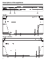
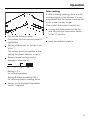
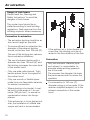
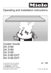
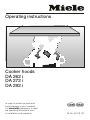
Operating instructions
Cooker hoods
DA 262 i
DA 272 i
DA 292 i
In order to protect yourself and
avoid damage to your machine,
it is absolutely necessary to read
the operating instructions prior
to installation and operation.
]ö
M.-Nr. 04 076 101
Description of the appliance
Description of the appliance
1
2
3
DA 262 i
4
5
6
8
7
DA 272 i / DA 292 i
4
2
5
6
7
8
Description of the appliance
Description of the appliance
The cooker hood is suitable for . . .
d - Slide switch for ,,Power selection“
. . . Air extraction:
Air is drawn in through the grease
filter f, cleaned and directed outside.
. . . Air recirculation:
Air is drawn in through the grease
filter f and then through the active
charcoal filters for cleaning. It is
passed back into the kitchen through
the top of the kitchen cabinet.
Before using for the first time, check
to see whether the active charcoal
filter is in place (see ”Cleaning and
Care“).
b - Slide switch for cooktop
illumination n
This is used to switch the cooktop illumination g on and off, regardless of
whether the cooker hood is in operation
or not. The deflector plate must be
pulled out about one inch for the light
to work.
0 - Light off
l - Light on
c - Slide switch for the fan m
This is used to switch the fan on and off.
0 - Fan off
l - Fan on
The power of the cooker hood can be
adjusted to the intensity of the kitchen
vapors and has four settings.
The fourth setting (Intensive setting)
should be selected for removing very
strong kitchen vapors.
low power.......strong power
e - Deflector plate
The deflector plate can be pulled out to
any extent up to its limit.
The action of pulling the deflector plate
out and pushing it in switches the
cooker hood on and off respectively.
The slide switch for the fan must be set
to setting ,, l “.
h - Grease filter retainer
This is used for securing or releasing
the grease filter f from the cooker
hood.
i The control panel can either
- be fitted with an aluminium front
facia panel, available from Miele,
- be fitted with a lightshield from the
kitchen furniture programme, or
- be installed without either of the
above, but with cover caps (supplied
for fitting at each end).
3
Contents
Contents
Description of the appliance . . . . . . . . . . . . . . . . . . . . . . . . . . . . . . . . . . . . . . . . . 2
Help to protect our environment. . . . . . . . . . . . . . . . . . . . . . . . . . . . . . . . . . . . . . 5
Warning and Safety instructions . . . . . . . . . . . . . . . . . . . . . . . . . . . . . . . . . . . . . 6
Operation . . . . . . . . . . . . . . . . . . . . . . . . . . . . . . . . . . . . . . . . . . . . . . . . . . . . . . . . 9
Cleaning and care . . . . . . . . . . . . . . . . . . . . . . . . . . . . . . . . . . . . . . . . . . . . . . . . 10
After Sales Service. . . . . . . . . . . . . . . . . . . . . . . . . . . . . . . . . . . . . . . . . . . . . . . . 12
Electrical connection . . . . . . . . . . . . . . . . . . . . . . . . . . . . . . . . . . . . . . . . . . . . . . 13
Technical data. . . . . . . . . . . . . . . . . . . . . . . . . . . . . . . . . . . . . . . . . . . . . . . . . . . . 14
Installation
Appliance dimensions . . . . . . . . . . . . . . . . . . . . . . . . . . . . . . . . . . . . . . . . . . . . . .
Wall unit dimensions . . . . . . . . . . . . . . . . . . . . . . . . . . . . . . . . . . . . . . . . . . . . . . .
Building in . . . . . . . . . . . . . . . . . . . . . . . . . . . . . . . . . . . . . . . . . . . . . . . . . . . . . . .
Depth alignment. . . . . . . . . . . . . . . . . . . . . . . . . . . . . . . . . . . . . . . . . . . . . . . . . . .
Fitting the light tube cover . . . . . . . . . . . . . . . . . . . . . . . . . . . . . . . . . . . . . . . . . . .
Removing the transit strips. . . . . . . . . . . . . . . . . . . . . . . . . . . . . . . . . . . . . . . . . . .
Fitting the cover caps. . . . . . . . . . . . . . . . . . . . . . . . . . . . . . . . . . . . . . . . . . . . . . .
Preparing the lightshield . . . . . . . . . . . . . . . . . . . . . . . . . . . . . . . . . . . . . . . . . . . .
Fitting the front facia panel / lightshield . . . . . . . . . . . . . . . . . . . . . . . . . . . . . . . . .
Dismantling . . . . . . . . . . . . . . . . . . . . . . . . . . . . . . . . . . . . . . . . . . . . . . . . . . . . . .
16
16
17
18
19
19
19
19
21
21
Air extraction . . . . . . . . . . . . . . . . . . . . . . . . . . . . . . . . . . . . . . . . . . . . . . . . . . . . 22
Air recirculation . . . . . . . . . . . . . . . . . . . . . . . . . . . . . . . . . . . . . . . . . . . . . . . . . . 24
4
Help to protect our environment
Help to protect our environment
Disposal of packaging
The transport and protective packing is
mostly manufactured from the following
re-usable materials:
. . . Corrugated paper / cardboard mostly from recycled materials.
. . . CFC-free molded polystyrene.
. . . Polyethylene foil (PE) partly from secondary raw materials.
Disposal of your old machine
Old machines contain materials which
can be recycled. Please contact your
local authorities or scrap merchant
about potential recycling schemes, before disposing of the appliance.
Read the notes on page 6 before disposing of the appliance.
Rather than just throwing these materials away, please take them to the
nearest local authority collection point
for specific waste.
5
Warning and Safety instructions
Warning and Safety instructions
Read these Operating Instructions carefully before installing or
using the Exhaust Hood.
This appliance is intended for
residential use only. Use the appliance only for its’ intended purpose. The manufacturer cannot be
held responsible for damages
caused by improper use of the
hood.
Read all the instructions before installing or using for the first time.
SAVE THESE INSTRUCTIONS AND
REVIEW THEM PERIODICALLY
This appliance is to be used for
ventilating cooking smoke / odors
only. Do not use it to vent hazardous or
flammable furnes or materials.
Be certain your appliance is
properly installed and grounded
by a qualified technician.
To guarantee the electrical safety
of this appliance, continuity must
exist between the appliance and an
effective grounding system. It is imperative that this basic safety requirement
be met. If there is any doubt, have the
electrical system of the house checked
by a qualified electrician. The manufacturer cannot be held responsible for
damages caused by the lack, or inadequacy of, an effective grounding system.
Do not allow children to play with
the hood or its controls.
6
Repairs on electrical appliances
should only be performed by qualified personnel. Do not repair or replace
any part of the appliance unless specifically recommended in this manual.
Before servicing, disconnect the
power supply by either removing
the fuse or manually “tripping” the circuit breaker.
Do not turn on the hood until it has
been proberly installed.
Do not connect the appliance to
the main electrical supply using an
extension cord. Extension cords do not
meet the safety requirements of this appliance.
Do not cook on an open flame beneath the exhaust hood. Flames
could be drawn up into the hood by the
suction or the grease filters may ignite.
Do not leave the cooktop unattended while in use. Overheated
food can ignite.
When installing the hood, make
sure that the minimum safety
distances between the cooktop and
hood are maintained.
– For electric cooktops: 18" (45 cm)
– For gas cooktops:
26" (65 cm)
Only metal ductwork should be
connected to the exhaust hood.
Any fittings, sealant, or materials used
to install the ductwork must be made of
non-flammable materials.
Warning and Safety instructions
Never connect an exhaust hood to
an active chimney, dryer vent, vent
flue, or room ventilating ductwork. Seek
professional advice before connecting
an exhaust hood vent to an existing, inactive chimney or vent flue.
Do not place this exhaust hood
over cooktops burning solid fuel.
Never operate gas burners without
pots. Heat generated by prolonged operation of gas burners without pots could damage the hood.
Do not use the exhaust hood without the grease filters in place.
Clean the grease filters regularly.
Saturated filters are a fire hazard.
Do not use a steam cleaner to
clean the hood. The steam could
penetrate to electrical components and
cause a short circuit.
To reduce the risk of cooking fires:
– Keep the fan, filters and cooking
area clean and free of grease.
– Turn on the hood when cooking at
high temperatures.
– Heat oils slowly. Only use the high
settings of the range or cooktop
when necessary.
– Never leave a turned on range or
cooktop unattended.
– Always use cookware and utensils
that are appropriate for the type and
amount of food being prepared.
When connecting the hood to an external vent, make sure that there is
adequate ventilation in the room
where the exhaust hood is to be
used.
When using the hood in the same area
as other appliances requiring room air
(e.g. non-electric water heaters, gas
cooktops, gas ovens, etc.) make certain that the air extracted by the hood
does not hinder their operation. These
appliances need air for combustion.
Adequate ventilation can be maintained by installing air vents in windows
or walls or by ensuring that the hood
can only be turned on when the other
appliances are off, or vice versa.
To prevent combustion gases being
drawn back into the room by the exhaust hood, the underpressure in the
room must be no greater than 6 psi
(0,04 mbar) when the hood and these
appliances are running simultaneously.
If there are any doubts as to whether
there is adequate ventilation, consult
an experienced professional.
The above ventilation restrictions
and warnings do not apply if the exhaust hood is retrofitted with an air
recirculation kit.
Do not use water on grease fires.
Smother any fire or flame, or use a
dry chemical or foam-type extinguisher.
7
Warning and Safety instructions
Warning and safety instructions
Disposal of discarded appliances
Before discarding an old appliance, disconnect its power cord to prevent it
from becoming a hazard.
SAVE THESE INSTRUCTIONS AND
REVIEW THEM PERIODICALLY
Throughout the manual, important
safety items will be highlighted in
boxes and should be read in conjunction with these “Warning and
Safety instructions”.
8
Operation
Operation
After cooking
If, after finishing cooking, there are still
cooking vapors in the kitchen, it is recommended that the cooker hood be left
on for some minutes longer.
Then switch the cooker hood off by:
moving the slide switch for the fan
and the cooktop illumination switch
to the ”0“ position.
Pull out the deflector plate.
Drop down the front control panel or
lightshield.
or
push the deflector plate in.
Set the slide switch for the fan to position ”l“.
The cooker hood will operate at the
setting the power selector is set to.
Select a power setting strong
enough to clear the air:
1
2
3
IS
Setting 1-2 =
for normal operation
Setting 3-Intensive setting (IS) =
for removing heavy cooking odors
Switch on the cooktop illumination
switch if required.
9
Cleaning and care
Cleaning and care
Before any cleaning or maintenance
work, the extractor must be disconnected from the mains supply
(switch off at the wall socket and
remove plug or the fuse).
Cleaning
The cooker hood housing may be
cleaned using hot water to which a little
mild detergent has been added.
Dry with a soft cloth.
Never use a cleaner which scours
or contains chlorine, acids or soda.
These would damage the surface of
the cooker hood.
To remove the grease filters push the
filter holder retainers towards the
middle.
Take out the grease filters.
DA 272 i, DA 292 i only:
Grease filters
Re-usable metal grease filters are builtin which remove solid particles (oil,
dust, etc.) from the kitchen vapors, preventing soiling of the cooker hood.
The grease filters can be cleaned in a
dishwasher or by hand.
The grease filters should be cleaned
regularly to ensure a trouble free operation of the extractor fan, at least every
1 or 2 months, or when they are visibly
saturated or no longer effective.
An over-greasy filter can lead to
danger or fire.
Press the clips at the side in using a
blunt instrument and remove the retainers. Pull the filter cassettes and
link pieces out for cleaning. Clean
the edges of the frame by hand. The
other parts can be cleaned in the
dishwasher.
Clean the grease filters . . .
. . . by hand: with a scrubbing brush
in hot water with detergent.
. . . in a dishwasher: place the filters with the short side upright in the
lower basket, ensuring the spray
arm is not obstructed.
After cleaning, leave the filters to dry
for a while on an absorbent surface
before putting back in place.
10
Cleaning and care
Cleaning and care
When removing the filters for cleaning, also clean off any residues of oil
or fat from the filter housing to prevent the risk of these catching fire.
DA 272 i, DA 292 i only: Put the filters
back together.
When re-inserting the filters ensure
that the locking device faces down
towards the cooktop.
If a filter is inadvertently replaced the
wrong way a round, use a small
screwdriver blade to unlock the filter
through the slots.
Changing the light tube and/or starter
Release the light tube and the starter
by turning them and then lifting them
out of their holders.
Replace the fluorescent tube or starter.
Inserting or changing the active
charcoal filters.
If the cooker hood is connected for recirculation, active charcoal filters must
be inserted, in addition to the grease filters. These filters absorb normal kitchen odors.
Pull out the deflector plate and
remove the rear grease filter.
Disconnect the cooker hood from
the mains supply (switch off at the
wall socket and remove plug or the
fuse).
When removing or changing the active charcoal filters, push the filter
holder retainers towards the middle.
When inserting the active charcoal filters, ensure that the locking device
faces down towards the cooktop.
The active charcoal filters should be
replaced when kitchen odors are not
being absorbed, at least every 3-4
months.
Unscrew the fixing screws at the left
and right hand side.
While doing so, hold the light cover
securely and then take it out.
11
After Sales Service
After Sales Service
In the event of any fault which you cannot correct yourself please contact
Your Miele Dealer
or
The Miele Service Department
The address of the nearest Service Department is given on the back page.
When contacting the Service Department, please quote the Model and Serial No. of the appliance, both of which
are shown on the data plate. This is
visible after removing the rear grease filter.
12
Electrical connection
Electrical connection
For CDN only:
The cooker hoods are supplied with a
1.50 m power supply cable ready for
connection to an a.c. single phase
120 V / 60 Hz supply.
Caution:
Ensure that power supply is OFF
during installation.
Important
The wires in the power supply cable
are colored in accordance with the following code:
Green = ground
Black = live
White = neutral
WARNING
THIS APPLIANCE MUST BE
GROUNDED
For USA only:
The cooker hoods are supplied with a
5 ft power supply cable ready for connection to an a.c., single phase,
120 V / 60 Hz supply. Connection
should be made in the junction box.
Important
The wires in the power supply cord are
colored in accordance with the following code:
Green/yellow = ground
Blue = neutral
Brown = live
As the colors of the wires in the power
supply cord of this appliance may not
correspond with the colored markings
identifying the terminals in your junction
box, proceed as follows:
The wire which is colored green and
yellow must be connected to the terminal junction box which is marked by the
letter E, or by the earth symbol z
or colored green or green and yellow.
The wire which is colored blue must be
connected to the terminal which is
marked with the letter N or colored
white.
The wire which is marked brown must
be connected to the terminal which is
marked with the letter L or colored
black.
WARNING
THIS APPLIANCE MUST BE
GROUNDED
13
Technical data
Technical data
Total rated load
Light
Voltage
Frequency
Fuse rating
Connection cable with plug
Maximum air throughput:
Air extraction
Air recirculation
14
DA 262 i
DA 272 i
DA 292 i
225 W
15 W
120 V
60 Hz
15 A
5 ft (1,5 m)
223 W
13 W
120 V
60 Hz
15 A
5 ft (1,5 m)
235 W
16 W
120 V
60 Hz
15 A
5 ft (1,5 m)
90-325 CFM
(150-550 m3/h)
90-325 CFM
( 150-550 m3/h)
90-325 CFM
(150-550 m3/h)
50-240 CFM
(80-350 m3/h)
50-240 CFM
(80-350 m3/h)
50-240 CFM
(80-350 m3/h)
Installation
Installation
For installing the cooker hood, a
cabinet is required. The minimum
cabinet width required for each model
is given below:
– DA 262 i = 600 mm (23 5/8")
– DA 272 i = 700 mm (21 9/16")
– DA 292 i = 900 mm (35 7/16")
The exhaust connection must be
made by a suitably qualified and
competent person.
The distance between the top of the
cooktop and the bottom of the
cooker hood should be at least:
45 cm (18") above electric cooktops
65cm (26") above gas cooktops.
Safety regulations prohibit the fitting
of a cooker hood over solid fuel
stoves.
15
Installation
Installation
Appliance dimensions
Wall unit dimensions
A: DA 262 i = 560; DA 272 i = 660; DA 292 i =860
B: DA 262 i = 595; DA 272 i = 695; DA 292 i =895
5 15
˝
/16˝ 415 /16
6 5/8˝
2˝
13/16˝
1313/16˝
25/16
˝
10 7
/16˝
A: DA 262 i = 22 1/16’’; DA 272 i = 26’’;
DA 292 i =33 7/8’’
B: DA 262 i = 23 5/8’’; DA 272 i =27 9/16’’;
DA 292 i=35 7/16’’
A: DA 262 i = 562-568 = 22 1/8" - 22 3/8"
DA 272 i = 662-668 = 26 1/16" - 26 5/16"
DA 292 i = 862-868 = 33 15/16" - 34 3/16"
B: DA 262 i = 600 = 23 5/8"
DA 272 i = 700 = 27 5/8"
DA 292 i = 900 = 35 1/2"
170-235 = 6 3/4" - 9 1/4"
135 = 5 3/8"
430 = 17"
110 = 4 11/16"
20 = 3/4"
285-350 = 11 1/4" - 13 7/8"
The dividing wall must be removable to enable the cooker hood to
be adjusted for height and depth.
515/16˝
107/16˝
max. 1615/16˝
* plus depth of control panel
16
Installation
Installation
Building in
Take the dividing wall out of the wall
unit.
Push the brackets into the slots on
the sides of the cooker hood.
19 mm ( 3/4 ") thick side walls:
Secure the support tracks to both
interior walls of the unit using two
3,5 x 16 mm ( 5/8 ") screws, position
as illustrated.
16 mm ( 5/8 ") thick side walls:
Fasten the brackets in place on the
cooker hood using the M 6 x 10 mm
hexagonal bolts and washers.
The thickness of the side walls must
be taken into account.
17
Installation
Installation
Lift the cooker hood into the unit
from below until the lugs of the
brackets lie above the support
tracks. Then carefully lower the
cooker hood. The lugs engage with
the support track.
Feed the air extraction or air re-circulation connector through as applicable, (see chapter ”Air extraction“ /
”Air re-circulation“).
Replace the dividing wall in the wall
unit.
Pull the deflector plate out to its limit
and remove the grease filters.
4 holes (DA 262 i / DA 272 i) or
6 holes (DA 292 i) are now visible.
Use a sharp pointed instrument
through these holes to gouge out the
fixing holes.
Then screw the cooker hood securely to underside of wall unit.
Replace the grease filters.
Depth alignment
To align the height, turn the
M 6 x 19 mm adjuster screws clockwise or anti-clockwise.
Move the cooker hood into its
correct position.
Units deeper than 285 mm require the
fitting of a spacer bar to prevent vapours collecting between the rear of
the cooker hood and the wall.
2
1
1
Secure the cooker hood on both
sides using four 3 x 16 mm
( 5/8 ")screws for each side.
18
To achieve the correct depth shorten
the . . .
. . . spacer bar at the required breaking points.
. . . End caps.
Fit the end caps (1) to both ends of
the spacer bar.
Installation
Installation
Attach the spacer bar to the guide
rail (2) located behind the light tube.
Fitting the light tube cover
– DA 262 i
Pull off the transit strips on each side.
Fitting the cover caps
For cooker hoods without a front panel
or lightshield:
Position the light tube cover and
screw into place (see diagram).
– DA 272 i, DA 292 i
Attach the extension pieces supplied
to the light tube cover, then position
the now extended light tube cover
and screw into place.
Removing the transit strips
Pull the deflector plate out to its limit.
Push the Allen screws from the
accessory kit onto the cover caps
until the screw heads lie directly
under the holes in the cover caps.
Secure the cover caps on both sides
of the deflector plate using the Allen
screws.
Preparing the lightshield
Lightshields . . .
. . . weighing up to 600 g can be fitted
normally.
. . . Those weighing over 600 g need to
have the springs in the snap fittings pretensioned:
19
Installation
Installation
Only use the template for lightshields
with the following lengths:
b
c
d
e
f
Pull out the snap fittings from the
slots on the left and right hand sides
of the deflector plate (1).
Press the baffle (2) into the engaging
point. Put the snap fittings back in
place.
The snap fitting with the hole must
be inserted on the right.
Do not wipe off any lubricant.
Hold the template supplied against
the back of the lightshield and mark
the drill hole positions for fixing the
hinges.
20
b
c
d
e
f
DA 262 i
DA 272 i
Da 292 i
598 mm
698 mm
898 mm
597 mm
697 mm
897 mm
596 mm
696 mm
896 mm
595 mm
695 mm
895 mm
599 mm
699 mm
899 mm
DA 262 i
23 9/16"
DA 272 i
27 1/2"
Da 292 i
35 3/8"
23 1/2"
27 7/16"
35 5/16"
23 1/2"
23 7/16"
27 7/16"
27 3/8"
35 5/16"
35 1/4"
23 9/16"
27 1/2"
35 3/8"
With other lengths adjust the measurements accordingly.
Installation
Fitting the front facia panel /
lightshield
Dismantling
Disconnect the appliance from the
electricity supply by unplugging at
the socket, or removing the mains
fuse.
Take the dividing wall out of the wall
unit.
Release the hose clip from the exhaust connection and push the hose
upwards.
Screw the hinges (2) supplied to the
left and right hand sides of the front
facia panel / lightshield (1).
With the Miele aluminium lightshield
the screws are supplied.
For lightshields with a Miele kitchen
furniture programme use
3.5 x 16 mm ( 5/8 " ) screws supplied.
Push the Allen screws from the accessory kit onto the cover caps until
the screw heads lie directly under
the holes in the cover caps.
Loosen the securing screws used to
screw the cooker hood to the side
walls.
Pull the deflector plate out to its limit
and remove the grease filters.
Remove the screws now visible
(DA 262 i / DA 272 i = 4;
DA 292 i = 6) using a Philips screwdriver.
Raise the cooker hood and then
lower it to remove.
Hold the front facia panel / lightshield against the deflector plate:
the holes in the hinges must lie over
the holes visible in the deflector
plate (3).
Secure the cover caps an fascia
panel / lightshield on both sides of
the deflector plate using the Allen
screws.
21
Air extraction
Air extraction
Danger of toxic fumes.
Please heed the ,,Warning and
Safety Instructions“ to avoid the
dangers of toxic fumes.
The cooker hood should be installed according to local building
regulations. Seek approval from the
building inspector where necessary.
Connection for extraction
– The extraction ducting should be as
short and straight as possible.
– To ensure efficient air extraction the
diameter of the exhaust ducting
should not be less than 125 mm (5").
The use of flat ducting also reduces
the air extraction efficiency.
– The use of exhaust ducting with a
diameter less than 125 mm (5") and
flat ducting increases the noise level
of the cooker hood.
– Only use wide radius bends. Tight
bends reduce the air throughput of
the cooker hood.
– Only use smooth or flexible pipes
made from non-flammable materials
for exhaust connection.
– Where ducting is horizontal, it must
be laid to slope away at 1 cm per
metre (1/8" per foot) , to ensure no
condensation drains into the appliance.
– If the exhaust air is to be ducted outside, the installation of a Miele telescopic wall vent is recommended.
22
– If the exhaust air is to be ducted into
a vent flue, the ducting must be directed in the flow direction of the flue.
Connection
Only use narrower diameter pipework where it is unavoidable, for
example where existing pipework
has to be used.
The narrower the diameter the lower
the performance and the noisier the
operation.
If a connection to 100 mm (4")
diameter piping is to be made, fit the
reducer supplied (adaptor) on to the
exhaust connection of the cooker
hood.
Air extraction
Air extraction
Measure the total length of the exhaust ducting to be used.
Add the appropriate length of additional piping to this figure (see table),
according to the number and type of
bends:
Type
of
bend
Push the ducting on to the cooker
hood exhaust connector or on to the
reducer (adaptor) and secure.
Note
If the exhaust ducting is to run through
rooms, ceiling space etc. where there
may be great variations in temperature
between the different areas, the problem of sweating or condensation will
need to be addressed.
The exhaust ducting will need to be
suitably insulated.
In addition to insulating the exhaust
ducting it may also be necessary in
some cases to install a suitable condensate trap to collect and evaporate any
condensate which may occur.
When installing a condensate trap,
ensure that it is located vertically
and if possible directly above the
exhaust connection.
Angle
of
bend
Radius of
bend
Length of
additional
piping
in inch in mm in foot
Wall
vent
duct
with
grill
and
flap
in
metres
3,3’
1.0
1
3/4
3/4
1/2
0.3
0.2
0.2
0.1
Smooth
interior
wall
bends
90°
90°
45°
45°
Elbow
bend
90°
45°
6 3/4
1 3/4
2.0
0.5
Bend
in
rent
hose
Flexible
piping
90°
2 1/2
0.7
1
1
3/4
3/4
3/4
1/2
0.35
0.3
0.2
0.2
0.15
0.1
90°
90°
90°
45°
45°
45°
5
10
5
10
5
10
20
5
10
20
125
250
125
250
125
250
500
125
250
500
Calculation of extraction ducting
A pipe diameter of 125 mm (5’’) should
ensure trouble-free extraction up to a
total pipe length of 33 m (108’’).
Determine the total pipe length as follows:
23
Air recirculation
Air recirculation
If site conditions are not suitable for the
cooker hood to be used for air extraction, the appliance must be converted
for recirculation.
Connection
The following parts are necessary for
this, available from your Miele Dealer or
from the Miele Spare Parts Department:
Conversion kit from extraction to recirculation
(Ø 125 mm, 5")
Active charcoal filter
Place the hose with the directional
grill on to the exhaust connection of
the cooker hood.
Secure the hose on the exhaust connection using a hose clip.
Ensure that the air outlet from the directional grill is pointed towards the
kitchen interior.
It should on no account point towards a wall.
Screw the directional grill to the wall
unit.
If there is a soffit, an appropriate
cut-out in the soffit must be made.
Insert the active charcoal filter in the
cooker hood (see chapter ”Cleaning
and Care“).
24
25
27
Alteration rights reserved / 44 / 001
CDN, USA - 1998
This paper is made from 100% chlorine-free bleached cellulose and therefore protects the environment.