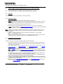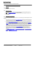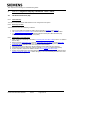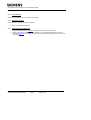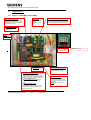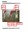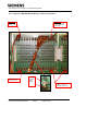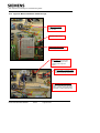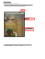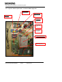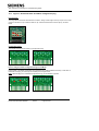
1
Title: Graphos Fault Finding and Troubleshooting Guide
Graphos Fault Finding and
Troubleshooting Guide
Document Authorisation
Role
Name
Prepared
D. Martin
by:
Reviewed
R. Martin
by:
Authorised
C. Whipps
by:
Function
Signed
Engineering Manager
Project Support Manager
Technical Support Manager
Document record
Issue Number
Date
A
31/08/05
B
15/08/05
1
09/12/05
04/09/0
2
7
Change Reference
PNB
DAM
FEF – RFC TS004029, Section 5.3 modified
This document is electronically held.
This is an unpublished work, the copyright of which vests in Siemens Plc. All rights reserved.
The information contained herein is the property of Siemens Plc. and is supplied without liability for
errors or omissions. No part may be reproduced or used except as authorised by contract or other
written permission. The copyright and the foregoing restriction on reproduction and use extend to all
media in which the information may be embodied.
Part Number 667/HE/31200/000
Issue 2
Page 1 of 39
Title: Graphos Fault Finding and Troubleshooting Guide
Contents
1
Safety Warning ..............................................................................................................5
2
Scope .............................................................................................................................5
3
Purpose..........................................................................................................................5
4
4.1
4.1.1
4.1.2
4.1.3
4.2
4.2.1
4.2.2
4.2.3
Main sign faults (identification and rectification)......................................................6
Non-illumination of an LED segment during sign operation....................................6
Symptom: ........................................................................................................................6
Reason(s) for fault: .........................................................................................................6
Identification and rectification:.........................................................................................6
The sign is blank and does not illuminate. ................................................................7
Symptom: ........................................................................................................................7
Reason(s) for fault: .........................................................................................................7
Identification and rectification:.........................................................................................7
5
5.1
5.1.1
5.1.2
5.1.3
5.2
5.2.1
5.2.2
5.2.3
5.3
5.3.1
5.3.2
5.3.3
5.4
5.4.1
5.4.2
5.4.3
5.5
5.5.1
5.5.2
5.5.3
5.6
5.6.1
5.6.2
5.6.3
5.7
5.7.1
5.7.2
5.7.3
LSCU 7-segment display Hardware Fault Codes ......................................................8
Hardware Fault Code (9C) ............................................................................................8
Fault Summary................................................................................................................8
Reason(s) for fault: .........................................................................................................8
Identification and rectification:.........................................................................................8
Hardware Fault Code (AE)............................................................................................9
Fault Summary................................................................................................................9
Reason(s) for fault: .........................................................................................................9
Identification and rectification:.........................................................................................9
Hardware Fault Code (AF)............................................................................................10
Fault Summary................................................................................................................10
Reason(s) for fault: .........................................................................................................10
Identification and rectification:.........................................................................................10
Hardware Fault Code (D9) ............................................................................................11
Fault Summary................................................................................................................11
Reason(s) for fault: .........................................................................................................11
Identification and rectification:.........................................................................................11
Hardware Fault Code (F0) ............................................................................................12
Fault Summary................................................................................................................12
Reason(s) for fault: .........................................................................................................12
Identification and rectification:.........................................................................................12
Hardware Fault Code (F1) ............................................................................................13
Fault Summary................................................................................................................13
Reason(s) for fault: .........................................................................................................13
Identification and rectification:.........................................................................................13
Hardware Fault Code (F2) ............................................................................................14
Fault Summary................................................................................................................14
Reason(s) for fault: .........................................................................................................14
Identification and rectification:.........................................................................................14
6
6.1
6.1.1
6.1.2
6.1.3
6.2
6.2.1
6.2.2
6.2.3
LSCU 7-segment display Communication Fault Codes............................................15
Communication Fault Code (A5) .................................................................................15
Fault Summary................................................................................................................15
Reason(s) for fault: .........................................................................................................15
Identification and rectification:.........................................................................................15
Communication Fault Code (A6) .................................................................................16
Fault Summary................................................................................................................16
Reason(s) for fault: .........................................................................................................16
Identification and rectification:.........................................................................................16
Part Number 667/HE/31200/000
Issue 2
Page 2 of 39
Title: Graphos Fault Finding and Troubleshooting Guide
6.3
6.3.1
6.3.2
6.3.3
6.4
6.4.1
6.4.2
6.4.3
Communication Fault Code (C4) .................................................................................17
Fault Summary................................................................................................................17
Reason(s) for fault: .........................................................................................................17
Identification and rectification:.........................................................................................17
Communication Fault Code (C5) .................................................................................18
Fault Summary................................................................................................................18
Reason(s) for fault: .........................................................................................................18
Identification and rectification:.........................................................................................18
7
7.1
7.1.1
7.1.2
7.1.3
7.2
7.2.1
7.2.2
7.2.3
7.3
7.3.1
7.3.2
7.3.3
7.4
7.4.1
7.4.2
7.4.3
7.5
7.5.1
7.5.2
7.5.3
7.6
7.6.1
7.6.2
7.6.3
7.7
7.7.1
7.7.2
7.7.3
7.8
7.8.1
7.8.2
7.8.3
7.9
7.9.1
7.9.2
7.9.3
7.10
7.10.1
7.10.2
7.10.3
7.11
7.11.1
7.11.2
7.11.3
LSCU 7-segment display Configuration Fault Codes ...............................................19
Configuration Fault Code (93) .....................................................................................19
Fault Summary................................................................................................................19
Reason(s) for fault: .........................................................................................................19
Identification and rectification:.........................................................................................19
Configuration Fault Code (95) .....................................................................................20
Fault Summary................................................................................................................20
Reason(s) for fault: .........................................................................................................20
Identification and rectification:.........................................................................................20
Configuration Fault Code (96) .....................................................................................21
Fault Summary................................................................................................................21
Reason(s) for fault: .........................................................................................................21
Identification and rectification:.........................................................................................21
Configuration Fault Code (98) .....................................................................................22
Fault Summary................................................................................................................22
Reason(s) for fault: .........................................................................................................22
Identification and rectification:.........................................................................................22
Configuration Fault Code (9A).....................................................................................23
Fault Summary................................................................................................................23
Reason(s) for fault: .........................................................................................................23
Identification and rectification:.........................................................................................23
Configuration Fault Code (9B).....................................................................................24
Fault Summary................................................................................................................24
Reason(s) for fault: .........................................................................................................24
Identification and rectification:.........................................................................................24
Configuration Fault Code (9D).....................................................................................25
Fault Summary................................................................................................................25
Reason(s) for fault: .........................................................................................................25
Identification and rectification:.........................................................................................25
Configuration Fault Code (9E) .....................................................................................26
Fault Summary................................................................................................................26
Reason(s) for fault: .........................................................................................................26
Identification and rectification:.........................................................................................26
Configuration Fault Code (9F) .....................................................................................27
Fault Summary................................................................................................................27
Reason(s) for fault: .........................................................................................................27
Identification and rectification:.........................................................................................27
Configuration Fault Code (A8).....................................................................................28
Fault Summary................................................................................................................28
Reason(s) for fault: .........................................................................................................28
Identification and rectification:.........................................................................................28
Configuration Fault Code (D8).....................................................................................29
Fault Summary................................................................................................................29
Reason(s) for fault: .........................................................................................................29
Identification and rectification:.........................................................................................29
8
LSCU 7-segment display System / Firmware Fault Codes .......................................30
9
Test Tools ......................................................................................................................30
Part Number 667/HE/31200/000
Issue 2
Page 3 of 39
Title: Graphos Fault Finding and Troubleshooting Guide
10
10.1
Configuration Tools ......................................................................................................30
Configuration Tools ......................................................................................................30
11
Configuration and Application software download procedure ...............................30
12
Contacts within Engineering .......................................................................................31
13
13.1
13.2
13.3
13.4
13.5
13.6
13.7
Appendix 1.....................................................................................................................33
Figure 1. LSCU (Main control PCB).............................................................................33
Figure 2. LDB (LED Driver Board) – LED string connections ..................................34
Figure 3. LDB (LED Driver Board) – Power connections..........................................35
Figure 4. Mains distribution within the sign...............................................................36
Figure 5. Light Sensor Connections and Input terminals.........................................37
Figure 6. Gemini option items, and 48 volt LED supply PSU ...................................38
Figure 7. Download link & Test Mode configuration plug ........................................39
Part Number 667/HE/31200/000
Issue 2
Page 4 of 39
Title: Graphos Fault Finding and Troubleshooting Guide
1
Safety Warning
Health and Safety at Work
Safety of Installation and Maintenance Personnel
In the interests of health and safety, when installing, using or servicing this type of equipment the following
instructions must adhered to:
(i) Prior to any work being started a Risk Assessment must be carried out.
(ii) Only trained and competent personnel are allowed to use and/or work on the equipment. All work shall
be carried out in accordance with the Electricity at Work Regulations 1989.
(iii) All personnel must adhere to the notes, cautions and warnings referenced within this Handbook or any
other Documents / Handbooks associated with this equipment which shall include, but is not restricted to,
the following:
(a)
The equipment must be correctly connected to the specified incoming power supply.
(b)
The equipment must be disconnected/isolated from the incoming power supply before
removing any protective covers or working on any part from which the protective covers
have been removed.
(c)
Any power tools and equipment must be regularly inspected and tested.
(d)
Any ladders used must be inspected before use to ensure they are sound and not
damaged.
(e)
When using a ladder, before climbing it, ensure that it is erected properly and is not liable
to collapse or move. If using a ladder near a carriageway ensure that the area is properly
coned and signed.
(f)
Any personnel working on site must wear the appropriate protective clothing, i.e. Hi-Vis
jackets, safety boots, etc.
It is important that all personnel are aware of the dangers posed to pedestrians and road users arising from
the installation, repair or maintenance work on traffic control equipment.
Personnel are to ensure that the work area is correctly signed and guarded, as per, the NRSWA 1991
Code of Practice, the primary objective of which is to warn and protect motorists and pedestrians from the
work being carried out and also for the protection of site personnel working within the works area.
Electrical Safety Warning.
All electrical work must be carried out in accordance with I.E.E. Wiring Regulations.
Be aware that live mains are present throughout the sign.
Particular care and attention should be taken when carrying out fault analysis voltage
measurements, documented and requested within sections of this maintenance guide.
Do isolate the sign, when possible i.e. when replacing faulty modules, PSU’s, cables,
etc.
2
Scope
This document covers all Siemens Graphos (Graphical VMS) sign types and variants, 667/1/37xxx/xxx.
3
Purpose
This document provides information on how to fault find a Graphos sign down to module level without the
need for any special tools. It also includes information on how to download configurations to a sign control
board in order that a substitute control board can be set up, if there is a requirement to replace one within a
sign.
Part Number 667/HE/31200/000
Issue 2
Page 5 of 39
Title: Graphos Fault Finding and Troubleshooting Guide
4
Main sign faults (identification and rectification)
4.1
Non-illumination of an LED segment during sign operation.
4.1.1
Symptom:
An LED segment does not illuminate during normal sign operation.
4.1.2
Reason(s) for fault:
1. One or more LED’s have failed on that particular LED string (segment).
(Note: The number of LED string failures allowed before a sign fails is user definable and system
configurable.
In general, if two LED string failures occur, a failsafe feature is initiated that causes the sign to
extinguish until such time as the string failures are rectified.
.
2. Lamp Driver Board (LDB) port(s) that the failing strings are connected to have gone faulty.
(Note: an LDB port is a bank of 8 LED string output connectors; there are 4 ports on an LDB board
giving 32 LED string output connectors in total).
Note: To make it easier to identify and trace which LED strings have failed and what LDB port they are
connected to, the individual LED string cables have been colour coded accordingly. The string colour
coding is as follows:
• Yellow – for flashing beacons or Textural enhancements / additions i.e. ‘SLOW DOWN’.
• Red – for red hazard warning ring.
• White – for assigned speed limit (numeric format), assigned hazard i.e. bend, junction ahead, etc.
(pictogram format) or textual enhancement i.e. ‘SLOW DOWN’ (word format).
4.1.3
Identification and rectification:
To identify and rectify a string failure the following steps should be followed:
1. Open the sign up and view the configuration sheets (a copy of which should be inside the sign or
available to the maintenance contractor), this will tell you which LDB’s and LDB ports the various
LED strings are connected to.
2. Remove the installed, site configuration plug from the configuration plug port and fit the test mode
configuration plug.
The sign should now continually cycle through all available aspects.
Note: A red LED on the LDB board will indicate which port the string failure has been detected on
but will not indicate which of the 8 LED string output connections has failed on that particular port.
3. Remove the string connectors from the LED string output connections on the offending LDB port,
one at a time.
If, when you pull a string connector out a string extinguishes, that particular string is OK, if this is
so, replace this string then carry on and pull the next string connector.
If when you pull a string out there is no visible change on any aspect, this will be the failed string.
Replace the faulty string to restore the sign to its normal operation.
4. If none of the above steps rectify the problem then the fault lies with one of the LED string output
connectors on the offending LDB port. Replace the Lamp Driver Board and reconnect the strings to
restore the sign to normal operation.
5. Remove the installed test mode configuration plug from the configuration plug port and replace it
with the site configuration plug, which was removed in step 1.
Part Number 667/HE/31200/000
Issue 2
Page 6 of 39
Title: Graphos Fault Finding and Troubleshooting Guide
4.2
The sign is blank and does not illuminate.
4.2.1
Symptom:
The sign is blank and does not illuminate.
4.2.2
Reason(s) for fault:
1. More than one LED string failure has occurred causing the sign to blank. (Refer to section 4.1)
Note: The 7-Segment LSCU display will still be illuminated.
2. Mains supply failure to sign. (Electricity Company supply fault, blown supply cut-out fuse, etc.)
3. LSCU mains fault.
4. Faulty LSCU.
4.2.3
Identification and rectification:
To identify and rectify the problem regarding a blank or non-illuminating sign, the following steps should be
followed:
1. Open the sign up and check that the two 7-segment displays and the green power/CPU OK LED
(located in the middle of the board) on the LSCU are illuminated. If these are not illuminated this
would indicate that there is no power to the LSCU.
2. Check that there is mains power to the LSCU by measuring the mains input voltage points on the
incoming mains distribution terminal block with a Digital Volt Meter (DVM), if there is mains then
work back through the mains distribution system using the numbered sequence in (Appendix 1,
figure 4). If there is no mains present then the mains supply to the sign needs to be checked out
for things like a blown supply cut-out fuse (G39 training and competency required) or local
Electricity company supply fault / power cut (to be reported to the local Electricity supplier) If an
LSCU mains fault has been identified, remove and replace the offending part(s), as necessary, to
restore power (i.e. cable connections to/from incoming mains supply, mains cable to LSCU, etc.)
3. If there is power to the LSCU then the two 7-segment displays should be illuminated and
displaying a system fault code that will identify the reason for the sign failure state. If the 7segment displays are not illuminated then this would indicate a faulty LSCU, replace LSCU as
necessary.
See (LSCU hardware fault codes), (LSCU communication fault codes), (LSCU configuration fault
codes).or (System / Firmware fault codes) for an explanation of what these faults mean and the
rectification required.
Part Number 667/HE/31200/000
Issue 2
Page 7 of 39
Title: Graphos Fault Finding and Troubleshooting Guide
5
LSCU 7-segment display Hardware Fault Codes
5.1
Hardware Fault Code (9C)
5.1.1
Fault Summary
The LSCU has detected fewer LDB boards than are configured for the system.
5.1.2
Reason(s) for fault:
This fault is due to one of the following conditions:
•
•
•
5.1.3
One or more LDB’s have failed (for LDB’s refer to Appendix 1, Figure 2 and Figure 3).
The comms & power link ribbon cable connection between the LSCU and 1st LDB has failed.
A comms & power link ribbon cable connection between subsequent LDB’s has failed (only
relevant if more than 1 LDB is used in the system).
Identification and rectification:
1. Firstly, check the connectivity of the linking comms & power link ribbon cable (LSCU to 1st LDB and
LDB to LDB).
2. Remove the site configuration plug from the configuration plug connector and fit the test mode
configuration plug. The sign should now continually cycle through the configured aspects.
3. Look at the sign to determine what colour strings are not illuminating.
4. Using the string colour coding trace back to determine which LDB’s are not functioning.
5. Check there is power on each LDB, (refer to Appendix 1, Figure 3 for measurement points).
6. If power is present, replace the LDB and refit the comms & power link ribbon cable.
7. If power is not present then check back along the LDB chain to the LSCU, ensuring that the failing
comms & power link ribbon cable / LDB is changed (i.e. the one immediately back down the chain
where the 5 volts re-appears.
Part Number 667/HE/31200/000
Issue 2
Page 8 of 39
Title: Graphos Fault Finding and Troubleshooting Guide
5.2
Hardware Fault Code (AE)
5.2.1
Fault Summary
The sign has detected a failure in its LED sensor system.
5.2.2
Reason(s) for fault:
This fault is due to one of the following conditions:
•
5.2.3
One or more LDB’s have failed.
Identification and rectification:
1. Change all LDB’s that have red LED’s illuminated on them and re-start the sign.
2. Double check after re-start that the fault code A.F. is not now being displayed along with any
illuminated red LED’s on the LDB’s as this would indicate that string failure(s) are now the cause
of the problem.
Part Number 667/HE/31200/000
Issue 2
Page 9 of 39
Title: Graphos Fault Finding and Troubleshooting Guide
5.3
Hardware Fault Code (AF)
5.3.1
Fault Summary
The sign has detected LED String failures.
5.3.2
Reason(s) for fault:
This fault is due to one of the following conditions:
•
5.3.3
There has been one or more string failures detected.
Identification and rectification:
1. Remove the normal operating site configuration plug (refer to Appendix 1, Figure 1) and fit the test
mode configuration plug. The sign should now continually cycle through the configured aspects.
2. Look at the LDB’s (refer to Appendix 1, Figure 2), red LEDs will indicate on what connector banks
there are string failures, if you also look at the sign you will visibly be able to see the LEDs (strings)
that are not illuminating.
3. Trace from the failed LEDs to the failing LDB connector bank and remove the connectors,
temporarily fit a replacement string of the correct colour to the vacated connector positions.
4. Repeat this until all failed strings have been identified and replaced.
5. Check there are no red LED’s showing on any of the LDB’s and that the fault code has cleared.
6. Remove the failed LED strings from the sign face and fit the LED’s from the newly fitted strings into
the lenses.
7. Re-loom the LED string wiring so that it stays neat and tidy.
8. Check the sign is operating normally.
9. Replace the test mode configuration plug with the, originally removed, site configuration plug and
check for normal operation of the sign.
Note: If prior to step 1 the sign is set by entering SGM0=1 and before step 9 the user checks
that Handset Command FLT displays FLT:!GRF 0 1 <sign being repaired>; this failure will now
be cleared automatically.
Part Number 667/HE/31200/000
Issue 2
Page 10 of 39
Title: Graphos Fault Finding and Troubleshooting Guide
5.4
Hardware Fault Code (D9)
5.4.1 Fault Summary
Invalid setting for the sign illumination time.
5.4.2
Reason(s) for fault:
This fault is due to one of the following conditions:
•
5.4.3
There has been an Invalid setting selected on the site configuration plug for the sign illumination
time (FP0 – FP3)
Identification and rectification:
1. Refer to the configuration section of the main handbook.
2. Ensure a valid time is selected. (Reference may need to be made to the customer of STC Poole
engineering to validate that the time selection is correct for the signs application).
Part Number 667/HE/31200/000
Issue 2
Page 11 of 39
Title: Graphos Fault Finding and Troubleshooting Guide
5.5
Hardware Fault Code (F0)
5.5.1
Fault Summary
Communication to light sensor failed.
5.5.2
Reason(s) for fault:
This fault is due to one of the following conditions:
•
•
•
5.5.3
Faulty connection from Light Sensor to LSCU.
Faulty Light Sensor.
Faulty LSCU.
Identification and rectification:
1. Check that the Light Sensor optical lens is clean and not obstructed.
2. Check the connection between the LSCU and the Light Sensor (refer to Appendix 1, Figure 5 and
Figure 1).
3. If the connections between the LSCU and the Light Sensor are sound, then replace the Light
Sensor.
4. If replacing the Light Sensor does not resolve the problem then replace the LSCU.
Part Number 667/HE/31200/000
Issue 2
Page 12 of 39
Title: Graphos Fault Finding and Troubleshooting Guide
5.6
Hardware Fault Code (F1)
5.6.1
Fault Summary
The measured lamp string voltage on the LDB board is too low.
5.6.2
Reason(s) for fault:
This fault is due to one of the following conditions:
•
•
5.6.3
Faulty PSU.
Faulty cabling or connections.
Identification and rectification:
1. Using a Digital Volt Meter (DVM) set to measure 48Vdc, measure the 48 volt LED supply on the
first LDB (the one connected directly to the LSCU).
(Refer to Appendix 1, Figure 3 for measurement points).
2. Work along the chain of LDB’s and replace / re-make connections as necessary to restore the 48
volts.
3. If 48 volts is not present on any of the LDB’s, then check the output of the LED 48 volts power
supply. Also check for mains input to the PSU.
4. If mains voltages are observed at the input but there is no 48V output, then replace the PSU.
5. If there is no mains input to the supply then (with the meter set to measure mains 230 Vac), check
back through the mains distribution (as outlined in figure 4)
6. Replace cables / connections as necessary to restore the supply.
Part Number 667/HE/31200/000
Issue 2
Page 13 of 39
Title: Graphos Fault Finding and Troubleshooting Guide
5.7
Hardware Fault Code (F2)
5.7.1
Fault Summary
No trigger signal was received, within a time interval, from the trigger mechanism (this may be an above
ground speed / vehicle presence detector or other similar device that provides a contact pair to trigger sign
activation)
5.7.2
Reason(s) for fault:
This fault is due to one of the following conditions:
•
•
5.7.3
Faulty detection device.
Incorrect wiring of detection device to sign.
Identification and rectification:
1. Check the trigger device has been wired up as per the appropriate device’s installation and
maintenance handbook. A trigger should be seen when an appropriate event occurs e.g. vehicle
approaches / vehicle approaches at or above correct speed.
2. With a meter set to measure d.c. voltage, check across the terminals. With no trigger, voltage
should be present. With a trigger (short circuit) there should be no voltage.
Part Number 667/HE/31200/000
Issue 2
Page 14 of 39
Title: Graphos Fault Finding and Troubleshooting Guide
6
LSCU 7-segment display Communication Fault Codes
It is possible to have Graphos signs connected to more complex communications systems and for this a
Gemini CPU is fitted. With this option the sign is communicated to via the Gemini which is connected to the
signs COMM1 input. In this case it is possible that errors in this communication from the Gemini to the sign
may occur and these will be recognised and flagged by the sign as an error code. The following
descriptions of these are intended to give guidance however analysis of the Gemini and instation requests
and / or slave sign comms interface, will be need to trace many of these errors, it is therefore not intended
to be a first line maintenance activity.
6.1
Communication Fault Code (A5)
6.1.1
Fault Summary
A command was received to show a picture which had an invalid picture number.
6.1.2
Reason(s) for fault:
This fault is due to one of the following conditions:
•
6.1.3
Conflict between configuration file and Gemini setup.
Identification and rectification:
1. Normally a sign with only one sign face which is either illuminated or not will have two valid picture
numbers 0 = not illuminated 1= illuminated. The configuration will have to be checked along with
the request from Gemini to ensure they line up.
Part Number 667/HE/31200/000
Issue 2
Page 15 of 39
Title: Graphos Fault Finding and Troubleshooting Guide
6.2
Communication Fault Code (A6)
6.2.1
Fault Summary
A command to show a picture from the outstation could not be processed correctly.
6.2.2
Reason(s) for fault:
This fault is due to one of the following conditions:
•
•
6.2.3
A configuration problem.
Communications problem.
Identification and rectification:
1. Test and replace the Gemini unit as necessary.
2. Check configuration, if necessary.
Part Number 667/HE/31200/000
Issue 2
Page 16 of 39
Title: Graphos Fault Finding and Troubleshooting Guide
6.3
Communication Fault Code (C4)
6.3.1
Fault Summary
An unknown message type was received by COM1 (interface to outstation).
6.3.2
Reason(s) for fault:
This fault is due to one of the following conditions:
•
6.3.3
Communications problem.
Identification and rectification:
1. Fault to be reported back to STC Engineering in Poole.
Part Number 667/HE/31200/000
Issue 2
Page 17 of 39
Title: Graphos Fault Finding and Troubleshooting Guide
6.4
Communication Fault Code (C5)
6.4.1
Fault Summary
An unknown message type was received from the slave sign (master to slave sign interface com 3).
6.4.2
Reason(s) for fault:
This fault is due to one of the following conditions:
•
•
6.4.3
Incorrect wiring of the RS485
No termination on the LSCU.
Identification and rectification:
1. Check RS485 wiring.
2. Check LSCU termination.
Part Number 667/HE/31200/000
Issue 2
Page 18 of 39
Title: Graphos Fault Finding and Troubleshooting Guide
7
LSCU 7-segment display Configuration Fault Codes
It is possible for errors to occur when the configuration is incorrect. This should never happen on installed
and operating signs, as the configuration will have been checked and tested in the factory. However they
are included for completeness and all such faults should be referenced to STC Engineering in Poole.
7.1
Configuration Fault Code (93)
7.1.1
Fault Summary
Incorrect system setup within sign configuration file.
7.1.2
Reason(s) for fault:
Configuration file has been setup incorrectly. This type of fault would be a very rare occurrence as all
configuration files are system checked and tested in the factory prior to shipment.
7.1.3
Identification and rectification:
Fault to be reported back to STC Engineering in Poole.
Part Number 667/HE/31200/000
Issue 2
Page 19 of 39
Title: Graphos Fault Finding and Troubleshooting Guide
7.2
Configuration Fault Code (95)
7.2.1
Fault Summary
Incorrect system setup within sign configuration file.
7.2.2
Reason(s) for fault:
Configuration file has been setup incorrectly. This type of fault would be a very rare occurrence as all
configuration files are system checked and tested in the factory prior to shipment.
7.2.3
Identification and rectification:
Fault to be reported back to STC Engineering in Poole.
Part Number 667/HE/31200/000
Issue 2
Page 20 of 39
Title: Graphos Fault Finding and Troubleshooting Guide
7.3
Configuration Fault Code (96)
7.3.1
Fault Summary
Incorrect system setup within sign configuration file.
7.3.2
Reason(s) for fault:
Configuration file has been setup incorrectly. This type of fault would be a very rare occurrence as all
configuration files are system checked and tested in the factory prior to shipment.
7.3.3
Identification and rectification:
Fault to be reported back to STC Engineering in Poole.
Part Number 667/HE/31200/000
Issue 2
Page 21 of 39
Title: Graphos Fault Finding and Troubleshooting Guide
7.4
Configuration Fault Code (98)
7.4.1
Fault Summary
Incorrect system setup within sign configuration file.
7.4.2
Reason(s) for fault:
Configuration file has been setup incorrectly. This type of fault would be a very rare occurrence as all
configuration files are system checked and tested in the factory prior to shipment.
7.4.3
Identification and rectification:
Fault to be reported back to STC Engineering in Poole.
Part Number 667/HE/31200/000
Issue 2
Page 22 of 39
Title: Graphos Fault Finding and Troubleshooting Guide
7.5
Configuration Fault Code (9A)
7.5.1
Fault Summary
Incorrect system setup within sign configuration file.
7.5.2
Reason(s) for fault:
Configuration file has been setup incorrectly. This type of fault would be a very rare occurrence as all
configuration files are system checked and tested in the factory prior to shipment.
7.5.3
Identification and rectification:
Fault to be reported back to STC Engineering in Poole.
Part Number 667/HE/31200/000
Issue 2
Page 23 of 39
Title: Graphos Fault Finding and Troubleshooting Guide
7.6
Configuration Fault Code (9B)
7.6.1
Fault Summary
Incorrect system setup within sign configuration file.
7.6.2
Reason(s) for fault:
Configuration file has been setup incorrectly. This type of fault would be a very rare occurrence as all
configuration files are system checked and tested in the factory prior to shipment.
7.6.3
Identification and rectification:
Fault to be reported back to STC Engineering in Poole.
Part Number 667/HE/31200/000
Issue 2
Page 24 of 39
Title: Graphos Fault Finding and Troubleshooting Guide
7.7
Configuration Fault Code (9D)
7.7.1
Fault Summary
Incorrect system setup within sign configuration file.
7.7.2
Reason(s) for fault:
Configuration file has been setup incorrectly. This type of fault would be a very rare occurrence as all
configuration files are system checked and tested in the factory prior to shipment.
7.7.3
Identification and rectification:
Fault to be reported back to STC Engineering in Poole.
Part Number 667/HE/31200/000
Issue 2
Page 25 of 39
Title: Graphos Fault Finding and Troubleshooting Guide
7.8
Configuration Fault Code (9E)
7.8.1
Fault Summary
Incorrect system setup within sign configuration file.
7.8.2
Reason(s) for fault:
Configuration file has been setup incorrectly. This type of fault would be a very rare occurrence as all
configuration files are system checked and tested in the factory prior to shipment.
7.8.3
Identification and rectification:
Fault to be reported back to STC Engineering in Poole.
Part Number 667/HE/31200/000
Issue 2
Page 26 of 39
Title: Graphos Fault Finding and Troubleshooting Guide
7.9
Configuration Fault Code (9F)
7.9.1
Fault Summary
Incorrect system setup within sign configuration file.
7.9.2
Reason(s) for fault:
Configuration file has been setup incorrectly. This type of fault would be a very rare occurrence as all
configuration files are system checked and tested in the factory prior to shipment.
7.9.3
Identification and rectification:
Fault to be reported back to STC Engineering in Poole.
Part Number 667/HE/31200/000
Issue 2
Page 27 of 39
Title: Graphos Fault Finding and Troubleshooting Guide
7.10
Configuration Fault Code (A8)
7.10.1 Fault Summary
Incorrect system setup within sign configuration file.
7.10.2 Reason(s) for fault:
Configuration file has been setup incorrectly. This type of fault would be a very rare occurrence as all
configuration files are system checked and tested in the factory prior to shipment.
7.10.3 Identification and rectification:
Fault to be reported back to STC Engineering in Poole.
Part Number 667/HE/31200/000
Issue 2
Page 28 of 39
Title: Graphos Fault Finding and Troubleshooting Guide
7.11
Configuration Fault Code (D8)
7.11.1 Fault Summary
Incorrect system setup within sign configuration file.
7.11.2 Reason(s) for fault:
Configuration file has been setup incorrectly. This type of fault would be a very rare occurrence as all
configuration files are system checked and tested in the factory prior to shipment.
7.11.3 Identification and rectification:
Fault to be reported back to STC Engineering in Poole.
Part Number 667/HE/31200/000
Issue 2
Page 29 of 39
Title: Graphos Fault Finding and Troubleshooting Guide
8
LSCU 7-segment display System / Firmware Fault Codes
It is possible for errors to occur within the Lamp Switch Card Universal (LSCU) and associated firmware.
Any error codes, other than those already explained within this document should be referred to STC
Engineering in Poole and the offending LSCU replaced until such time as STC Engineering identify and
rectify the cause of the fault.
9
Test Tools
1. Test mode configuration plug . This is installed in place of the site configuration plug to allow
the sign to be put into test mode allowing easier observation of failed strings. (Refer to
Appendix 1, Figure 1 for position of configuration plug connector).
10
Configuration Tools
10.1
Configuration Tools
1. Bluetooth XDA (used if a SieCom unit is fitted within the sign) or PDA with RS232 port (neither
of these devices are currently available).
Both of the above devices shall be:
a) Battery operated. (This is because there will be no supply available from the sign
b) Capable of running Java Applications.
2. A Siemens laptop with RS232 port (this is the only device available to carry out this function at
present).
Note: Most modern laptop’s have no RS232 ports but have USB ports, if using one of these
laptops a USB to RS232 dongle will be required.
The above device shall be:
a) Battery operated. (This is because there will be no supply available from the sign.
b) Capable of running Java Applications.
3. RS232 cable – (9 way male to 9 way female straight through).
4. Bedien tool. Installed on XDA, PDA or laptop.
5. Download link (1/0.6 wire).
6. Configuration storage media:
Where the sign is installed in a remote location and / or short repair times are required it may
be considered necessary to store the configuration and firmware locally within the sign.
Storage media suitable for the tools in use locally on the maintenance contract will be required
with a capacity of at least 600 KB, to allow for the storage of both the configuration data files
and application firmware. The configuration data, firmware and Java download tool are freely
available from STC upon request, please quote sign type number 667/1/37xxx/xxx, noted on
the label inside the sign (to select the correct sign configuration data). This can be delivered by
email or on CD by post. Please contact the Commercial Department on 01202 782199.
11
Configuration and Application software download procedure
At present neither the Bluetooth XDA nor PDA devices are available for the download facility therefore a
laptop is required to carry out this function. All engineers involved in the maintenance of Graphos signs will
need to setup their own directory structure and directory naming convention on the laptop used for
Part Number 667/HE/31200/000
Issue 2
Page 30 of 39
Title: Graphos Fault Finding and Troubleshooting Guide
download. An example is given below, the naming convention given as an example, is referenced
throughout the download procedure.
Directory structure and naming convention for Configuration and download files.
C:\Products\Graphos\Flash> --------
The Flash (download) facility resides in this directory.
C:\Products\Graphos>
This directory should contain the following files:FLASHCFG.BAT ---Batch Utility
FLASHVAS.BAT ---Batch Utility
VRSG.CFG
---Configuration Memory config
VRSG.H86
---The config H86 file.
VAS.CFG
---Application memory config
VAS.H86
---Application H86 file.
--------
The VRSG and VAS files are sign specific and should be obtained (copied) from the TIE server:Check the sign label, located within the sign itself, for the configuration part number e.g.
667/CF/37301/010. Copy the configuration files (VRSG.CFG, VRSG.H86) from the directory titled with the
configuration part number e.g. TIE\Graphos for Production\667_CF_37301_010> to C:\Products\Graphos>.
Copy the latest version of the Application Firmware (VAS.H86, VAS.CFG) from the directory TIE\Graphos
for Production\Application Firmware\Latest Version> to C:\Products\Graphos>.
Note: The Application Firmware version, loaded in the sign, can be checked using the Bedien tool.
The use of the existing Bedien tool has not been described in this document as there has yet to be a
decision made on whether this tool will be used or not, especially given its limited functionality. Possible
replacements are currently being investigated.
1. Fit the Download link, and press the LSCU reset button (or cycle the power).
2. Establish a connection between the Laptop (or Bluetooth XDA, SieCom unit, and PDA when
available) and the LSCU by connecting an RS232 cable from the Laptop 9 way ‘D’ connector to the
LSCU connector X5.
3. Ensure that the appropriate sign specific configuration files (VAS.CFG, VAS.H86, VRSG.CFG,
VRSG.H86) reside within the C:\Products\Graphos> directory.
4. Download config file:a.
b.
c.
d.
e.
f.
g.
Open a DOS session on the PC.
Change directory to C:\Products\Graphos> (Type in cd \products\graphos).
Type FLASHCFG and hit enter to download the config.
Follow on-screen instructions.
Type FLASHVAS and hit enter to download the application.
Follow on-screen instructions.
Type exit to end the DOS session.
Note:
If the first attempt to download the config fails it may be necessary to repeat step c above.
12
Contacts within Engineering
For any questions, queries or problems relating to this document please contact the Engineering
Department, Siemens Traffic Controls Ltd., Sopers Lane, Poole.
Departmental contacts are as follow:
Part Number 667/HE/31200/000
Issue 2
Page 31 of 39
Title: Graphos Fault Finding and Troubleshooting Guide
Dave Martin – Engineering Manager – (01202) 782188 – [email protected]
Part Number 667/HE/31200/000
Issue 2
Page 32 of 39
Title: Graphos Fault Finding and Troubleshooting Guide
13
Appendix 1
13.1
Figure 1. LSCU (Main control PCB)
7-Segment display (x2)
Green LED
Illuminated if power to LSCU. Will
display [00] if the sign is functioning
correctly or a fault code if there are
any faults on the sign.
1) On if power to
PCB
2) Flashes if CPU
O.K.
Download selection mode port (A link)
A download link is fitted here to put the
sign into download mode where it is able to
accept configurations and new firmware.
Mains input to LSCU
Generates logic supply
for all PCBs
LSCU
Reset button
-
+
5 Volts on LSCU
Light Sensor
Input connector.
Configuration plug connector
The configuration plug pcb now supplied is
a double header that can have one side
configured as the test configuration and the
other as the normal running configuration.
1) Site configuration plug (667/2/31249/000) This is used to set
some basic customer configuration
options.
2) Test configuration plug
(667/2/31249/000)
This is used to switch the sign into test
mode allowing a visual inspection of the
failures on the sign
Part Number 667/HE/31200/000
Issue 2
Page 33 of 39
Control & power connector
Control & power ribbon cable
connection from LSCU to first
LDB (Led Driver Board).
Maintenance port
Used for downloading new
configurations via PC / PDA
(requires a PC/PDA software
package).
Note: Does not support a
handset.
Formatted: Font: 9 pt
Title: Graphos Fault Finding and Troubleshooting Guide
13.2
Figure 2. LDB (LED Driver Board) – LED string connections
Associated LED
string output
connection port
(Connectors 9 – 16)
Associated LED
string output
connection port
(Connectors 1 – 8)
Red LED indicates
string failure in
strings on
associated port.
(Connectors 9 – 16)
Red LED indicates
string failure in
strings on
associated port.
(Connectors 1 – 8)
Part Number 667/HE/31200/000
Red LED indicates
string failure in
strings connected
to associated port.
Red LED indicates
string failure in
strings connected to
associated port.
Associated LED
string output
connection port
(Connectors 25–32)
Associated LED
string output
connection port
(Connectors 17–24)
Issue 2
Page 34 of 39
Comms & power link cable
Communications and power
link ribbon cable from
previous LDB (or from LSCU if
this is first LDB).
Title: Graphos Fault Finding and Troubleshooting Guide
13.3
Figure 3. LDB (LED Driver Board) – Power connections
Black wire
48 volt LED
supply – ve
Black wire
48 volt LED supply
– ve link between
LDB PCBs.
+
Red wire 48 volt
LED supply + ve
5 Volts
from
LSCU
Red wire 48 volt LED
supply + ve link
between LDB PCBs.
-
Part Number 667/HE/31200/000
Issue 2
Page 35 of 39
Title: Graphos Fault Finding and Troubleshooting Guide
13.4
Figure 4. Mains distribution within the sign
(2) Mains terminal block
Mains input to the LSCU
and LED PSU
(1) Mains input to LSCU
Switch Mode power supply
Generating 48 volts for LED’s
(3) Mains Switch
Mains switch supply to the sign.
(NB when checking for mains
continuity check input and
output.)
(4) Mains filter on incoming supply
(NB when checking for mains
continuity check input and output.)
(5) Incoming mains terminal block
Connector block into which the sign
supply is terminated after originating
from an electricity authorities supply
termination or mains distribution unit.
Part Number 667/HE/31200/000
Issue 2
Page 36 of 39
Title: Graphos Fault Finding and Troubleshooting Guide
13.5
Figure 5. Light Sensor Connections and Input terminals
Light Sensor
optical lens
Input terminals
Refer to label for exact functions.
Light Sensor connection.
Connection from the Light
Sensor to the LSCU. (refer
also to figure 1 LSCU).
Part Number 667/HE/31200/000
Issue 2
Page 37 of 39
Title: Graphos Fault Finding and Troubleshooting Guide
13.6
Figure 6. Gemini option items, and 48 volt LED supply PSU
Switch mode PSU
Associated with
optional Gemini
CPU
Gemini unit
When option fitted
Last gasp battery
Support associated
with optional Gemini
CPU
GSM Modem
Associated with
optional Gemini
CPU
48 volt output
of switch mode
PSU.
Mains input to
48 volt switch
mode PSU.
48 volt switch mode PSU.
48 volt PSU LED
output supply to LDB’s
Part Number 667/HE/31200/000
Issue 2
Page 38 of 39
Title: Graphos Fault Finding and Troubleshooting Guide
13.7
Figure 7. Download link & Test Mode configuration plug
Download Link
The image below shows the download link connection. Using a short length of wire (1/0.6) as a link, insert
one end of the wire into pin 3 and the other into pin 8 of the download link connector (X13), as shown
below.
Configuration Plugs
The images below show both sides of a Configuration Plug
Plug side 1
Plug side 2
How to configure a blank Configuration Plug for Test Mode
Using a blank / unmodified configuration plug (Siemens part number 632905-N110-U22), cut the links on
both sides of the plug, as shown (by the red dots) in the images below.
Note: Label this plug as a ‘Test Mode Configuration Plug’, for identification purposes.
Part Number 667/HE/31200/000
Issue 2
Page 39 of 39