1
ODEL
BER 917.258524
OWNER'S MANUAL
®Assembly
®Operation
®Customer Responsibilities
o Service and Adjustments
®Repair Parts
CAUTION:
Read and follow
FOR CONSUMER
ib_l m
all safety
ASSISTANCE
rules and instructions
before operating
HOT LIN E, CALL THIS TOLL FREE NUMBER:
this equipment.
1-800-659-5917
SAFETY RULES
_
Safe Operation Practices for Ride-On
Mowers
IMPORTANT: THIS CUTTING MACHINE IS CAPABLE OF AMPUTATING HANDS AND FEET AND THROWtNG OBJECTS_
FAILURE TO OBSERVE THE FOLLOWING SAFETY INSTRUCTIONS
COULD RESULT IN SERIOUS INJURY OR DEATH.
I.
•
•
•
•
•
•
•
•
o
•
•
•
•
°
ii.
I!1. CHILDREN
GENERAL OPERATION
Read, understand, and follow all instructionstn the manual
and on the machlne before starting.
Only allow responsible adults, who are familiar with the
instructions, to operate the machine..
Clear the area of objects such as rocks, toys, wire, etc.,
which could be picked up and thrown by the blade.
Be surs the area isclear of other people before mowingo Stop
machine if anyone enters the area.
Never carry passengers,.
Do not mow in reverse unless absolutely necessary, Always
look down and behind before and while backing..
Be aware of the mower discharge directionand do notpoint
it at anyone. Do not operate the mower without either the
entire grass catcher or the guard in place.
Slow down before turning.
Never leave a running machine unattended. Always turnoff
blades, set parking brake, stop engine, and remove keys
before dtsmounting_
Turn off blades when not mowing.
Stop engine before removing grass catcher or unclogging
chute,
Mow only in daylight or good artificial llghL
Do not operate the machine while under the Influence of
alcohol or drugs.
Watch for traffic when operating near or crossing roadways.
Use extra care when loading or unloading the machine into
a trailer or truck..
Tragic accidents can occur if the operator is not alert to the
presence of children. Children are often attracted to the
machine and the mowing activity.
Never assume that
children will remain where you last saw them°
°
Keep children out of the mowingarea and under the watchful
care of another responsible adult..
*
Be alert and turn machine off if children enter the area..
°
Before and when backing, look behind and down for sinai(
children.
o
Never cam] children. They may fail off and be seriously
injured or interfere with safe machine operation.
,
Never allow children to operate the machine.
°
Use extra care when approaching blind comers, shrubs,
trees, or other objects that may obscure vision,
IV. SERVICE
=
Use extra care in handlinggasoline and other fuels, They are
flammable and vapors are explosive_
Use onfy an approved container°
Never remove gas cap or add fuel with the engine
running. Aliow engine to cool before refueltng_ Do not
smoke.
Never refuel the machine indoors_
Never store the machine or fuel container inside where
there is an open flame, such as a water heater.
=
Never run a machine inside a closed area,
•
Keep nuts and bolts, especially blade attachment botts, tight
and keep equipment tn good condition,
•
Never tamper with safety devices. Check their proper
operation regularly.
°
Keep machine free of grass, leaves, or other debris bu[Id-upo
Clean oil or fuel spiIlage_ Allow machine to cool before
stodng.
=
Stop and inspect the equipment if you strike an object.
Repair, if necessary, before restarting.
•
Never make adjustments or repairs with the engine running.
•
Grass catchercomponents are subjectto wear, damage, and
deterioration, which could expose moving parts or allow
objects to be thrown. Frequently check components and
replace with manufacturer's recommended parts, when necessary.
°
Mower bladesaresharpand can cut.Wrap theblade(s)
or
wear gloves,and use extracautionwhen servicing
them.
•
Check brake operation
frequently.
Adjustand serviceas
required,
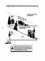
SLOPE OPERATION
Slopes are a major factor related to loss-of-control and
tipover accidents, which can result in severe injury or death.
All slopes require extra caution, if you cannot back up the
slope or if you feel uneasy on it, do not mow it.
DO:
o
Mow up and down slopes, not across.
°
Remove obstacles such as rocks, tree limbs, etco
•
Watch for holes, ruts, or bumps. Uneven terrain could
overturn the machine. Tall grass can hide obstacles.
•
Use slow speed. Choose a low gear so that you will not have
to stop or shift while on the slope.
o
Follow the manufacturer's
recommendations for wheel
weights or counterweights to improve stability..
•
Use extra care with grass catchers or other- attachments.
These can change the stability of the machine,.
•
Keep all movement on the slopes slowand gradual,. Do not
make sudden changes [n speed or direction.
°
Avoid starting or stopping on a slope. If tires lose traction,
disengage the blades and proceed slowly straight down the
slope_
DO NOT:
•
Donot turnon slopes unlessnecessary, andthen turnslowly
and gradually downhill, if poss bleo
•
Do not mow near drop-offs, ditches, or embankments. The
mower could suddenly turn over if a wheel is over the edge
of a cliffor ditch, or if an edge caves in_
•
Do not mow on wet grass, Reduced traction could cause
slidtng.
°
Do not tryto stabilize the machine by putting yourfoot on the
ground.
•
Do not use grass catcher on steep slopes,
portant safety precautions.
It means
CAUTIONII!
BECOME
ALERT!!!
YOUR
Look
for
thls
symbol
to
POint
out
im'
SAFETY IS INVOLVED. ...............
1
_
I
|
I
|
|
_
_
i,m
m'H
-
•
CAUTION: Always disconnect spark plug
wire and placewlre whereit cannot contact
spark plug in order to prevent accidental
starting when setting up, transporting,
adjusting or making repairs.
'
HH,{
II
IIHHl{
'1
, II
...........
WARNING A
The engine exhaust from this product contains cliemicals known to the State of California to cause cancer, birth defects, or other
reproductive harm.
2
........................................
II
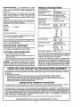
PRODUCT SPECIFICATIONS
CONGRATULATIONS
on your purchase of a Sears
Tractor, It has been designed, engineered and manufactured to give you the best possible dependability and
performance.
Should you experience any problem you cannot easity
remedy, please contact your nearest Sears Authorized
Service Center/Departmento We have competent, welltrained technicians and the proper tools to service or repair
this tractor.
Please read and retain this manual. The instructions will
enable you to assemble and maintain your tractor properlyo
Always observe the "SAFETY RULES".
MODEL
NUMBER
HORSEPOWER:
15.5
GASOLINE CAPACITY
AND TYPE:
1.25 GALLONS
UNLEADED REGULAR
OIL TYPE (API-SF/SG/SH):
SAE 30 (above 32°F)
SAE 5W_30 (below 32°F)
OIL CAPACITY:
3,0 PINTS
SPARK PLUG:
(GAP: .030")
CHAMPION RJ19LM
VALVE CLEARANCE:
INTAKE:
°005" - .007"
EXHAUST: .009" - .011"
GROUND SPEED (MPH):
FORWARD:
1st
2rid
3rd
4th
5th
6th
REVERSE:
917_258524
SERIAL
NUMBER
DATE OF PURCHASE
THE MODELAND SERIAL NUMBERS WILL BE FOUND
ON A PLATE UNDER THE SEAT.
YOU SHOULD RECORD BOTH SERIAL NUMBER AND
DATE OF PURCHASE AND KEEP IN A SAFE PLACE
FOR FUTURE REFERENCE°
MAINTENANCE
AGREEMENT
TIRE PRESSURE:
FRONT:
REAR:
CHARGING SYSTEM:
3 AMPS BATTERY
5 AMPS HEADLIGHTS
BATTERY:
AMP/HR:
MINo CCA:
CASE SIZE:
BLADE BOLT TORQUE:
30-35 FT. LBS.
A Sears Maintenance Agreement is available on this prod_
ucto Contact your nearest Sears store for details.
CUSTOMER
=
.
RESPONSIBILITIES
Read and observe the safety rules.
Followa regular schedule in maintaining,caring forand
using your tractor.
1.1
1.5
2.3
345
4.4
5,7
1.7
14 PSI
10 PSi
25
190
U1R
with a spark arrester meeting applicable local or state laws
(if any)_ If a spark arrester is used, it should be maintained
in effective working order by the operator.
In the state of California the above is required by law
(Section 4442 of the California Public Resources Code)_
Other states may have similar laws. Federal laws apply on
federal lands. A spark arrester for the muffler is available
through your nearest Sears Authorized Service Center/
Department (See REPAIR PARTS section of this manual).
°
Follow the instructions under "Customer Responsibilities and Storage" sections of this owner's manual.
WARNING:
This tractor is equipped with an internal
combustion engine and should not be used on or near any
unimproved forest-covered, brush-covered or grass-covered land unless the engine's exhaust system is equipped
LIMITED TWO YEAR WARRANTY ON CRAFTSMAN
RIDING EQUIPMENT
For two (2) years from the date of purchase, if this Craftsman Riding Equipment is maintained, lubricatedand tuned up according
to the instructionsin the owner's manual, Sears will repairor replace, free of charge, any parts found to be defective in material or
workmanship.
This Warranty does not cover:
•
Expendable items which become worn during normal use, such as blades, spark plugs, air cleaners, belts, etc,.
°
Tire replacement or repaircaused by puncturesfrom outsideobjects,such as nails, thorns, stumps, or glass,
•
Repairs necessary because of operator abuse, negligence, improper storage or accident or the failure to maintain the
equipment accordingto the Instructions contained in the owner's manual°
,
Riding equipment used for commercialor rental purposes°
LIMITED 90 DAY WARRANTY ON BATTERY
For ninety (90) days from date of purchase, if any battery included with this riding equipment proves defective in material or
workmanship and our testing determines the battery will not hold a charge, Sears will replace the battery at no charge°
IN-HOME WARRANTY SERVICE ON YOUR CRAFTSMAN RIDING EQUIPMENT IS AVAILABLE AT NO*CHARGE FOR 30
DAYS FROM THE DATE OF PURCHASE. PLEASE CONTACT YOLIR NEAREST SERVICE CENTER. AFTER 2,0 DAYS FROM
THE DATE OF PURCHASE, WARRANTY SERVICE IS AVAILABLE BY TAKING YOUR CRAFTSMAN RIDING EQUIPMEkFI" TO
YOUR NEAREST SEARS SERVICE CENTER. (IN-HOME WARRANTY SERVICE WILL STILL BE AVAILABLE AFTER 30 DAYS
FROM THE DATE OF PURCHASE BUT A STANDARD TRIP CHARGE WILL APPLY.) THIS WARRANTY APPLIES ONLY
WHILE THIS PRODUCT IS IN THE UNITED STATES..
This Warranty gives you specific legal rights, and you may also have other rightswhich may vary from state to state_
SEARS,
i ii
ROEBUCK
AND CO., D/817 WA, HOFFMAN
ii iiiiii
.....................................
3
ESTATES,
IL 60179
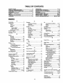
TABLE OF CONTENTS
SAFETY RULES ............................................................ 2
PRODUCT SPECIFICATIONS ...................................... 3
CUSTOMER RESPONSIBILITIES ..................... 3, 15-19
WARRANTY ..................................................................
3
TABLE OF CONTENTS ................................................ 4
INDEX ............................................................................
4
TRACTOR ACCESSORIES .......................................... 5
ASSEMBLY ................................................................ 7-9
OPERATION ........................................................... 10-14
MAINTENANCE SCHEDULE ...................................... 15
SERVICE AND ADJUSTMENTS ............................ 20-25
STORAGE ................................................................... 26
TROUBLESHOOTING ............................................ 27-28
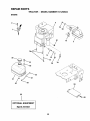
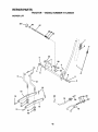
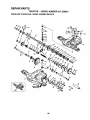
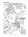
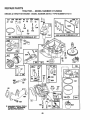
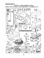
REPAIR PARTS - TRACTOR ................................. 30-47
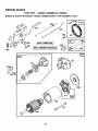
REPAIR PARTS- ENGINE .................................... 48-53
PARTS ORDERING/SERVICE .................. BACK PAGE
INDEX
A
Accessories ..................................................
5
Adjustments:
Brake ....................................................
22
Carburetor .......................................25
Mower:.
Front-To-Back ..............................
2t
Side-To-Side .................................
21
Throttle Control Cable ....................24
Air Filter, Engine .........................................
t8
Air Screen, Engtne ....................................
18
Assembly ......................................................
7-9
B
Battery:
Charging .........................................7-8
Cleaning .......................................... 17
Connecting .................................. 7-8
Starting with Weak Battery ...........23
Storage .............................................
26
Terminals ....................................... 17
Belts:
Motion Drive
Removal/Replacement ........... 22
Mower Blade Drive
Removal/Replacement ..............22
Blade:
Sharpening .........................................
16
Replacement ................................ 16
Brake Adjustment .....................................
22
C
Carburetor Adjustment ..........................25
Controls, Tractor ................................. 1t
Customer Responsibilities ................15-19
Engine:
Air Filter ..................................... 18
Alr Screen, Engine .................. 18
Battery ........................................ 17
Cooling Fins, Engine ............... 18
Engine Oll ....................................17
Fuel Filter ....................................19
Spark Plugs ................................ 19
Tractor:.
Blades ..............................................
16
Lubrication Chart ....................... i5
Maintenance Schedule ........... 15
Tire Care ........................... 8,16,23
Cutting Height, Mower ........................ 12
E
Electrical:
Interlocks and Relays .....................
24
Schematic .......................................29
Wiring Diagram ..............................30
Engine:
Air Filter............................................18
Air Screen ........................................18
Cooling Fins, Engine ......................18
Oil Change .................................... 17
Oil Level .......................................
t3,17
Oil Type ...........................................17
Preparation .........................................
t3
Repair Parts ................................
48-53
Starting.............................................14
Storage .......................................... 26
F
Filters:
Air ........................................................
18
Fuel ................................................. 19
Fuel:
Type ..................................................13
Storage ............................................26
Fuse ....................................................... 24
G
Gauge Wheels ........................................ 8
H
Hood Remova!iInstallation .................. 24
L
Leveling Mower Deck .......................... 21
LubricationChart ................................ 15
M
Maintenance Schedule ........................ 15
Mower:
Adjustment, Front-to-Back .......... 21
Adjustment, Side-to-Side ................
21
Blade Sharpening ....................... 16
Blade Replacement ...................... 16
Cutting Height .............................. 12
Installation .......................................20
Operation ...................................... 13
Removal ...........................................20
Mowing Tips ............................................14
Muffler .................................................. 19
Spark Attester ........................... 3,40
Mulcher Plate ...............................................
9
O
Oil:
Cold Weather Conditions .........13,17
Engine ..............................................17
Storage ......................................... 26
Operation ..............................................
11-14
Operating Mower ................................. 13
Options:
Accessories ..........................................
5
Spark Arrester ............................ 3,40
P
Parking Brake .................................. 11-12
Parts Bag ................................................ 6
Parts, Replacement/Repair ........... 30-47
Product Specifications............................ 3
R
Repair Parts .................................... 30-47
S
Safety Rules .......................................... 2
Seat ......................................................
8
Service and Adjustments .............. 20-25
Brake
22
Carburetor ..................................... 25
Fuse .............................................. 24
Hood Removal/Installation .......... 24
Motion Drive Belt
RemovaL/Replacement .............22
Mower Blade Drive Belt
Removal/Replacement ........... 22
Mower Adjustment:
Front-to-Back .......................... 21
Side-to-Side ............................ 2t
Mower fnstaflatlon ........................ 20
Mower Removal .......................... 20
Tire Care ............................. 8,16,23
Slope Guide Sheet .............................. 55
Spark Ptugs........................................... 19
Specifications ........................................ 3
Starting the Engine ........................ 13-14
Steering Wheel ................................. 7,23
Stopping the Tractor ........................... 12
Storage ................................................... 26
.............................................
T
Throttle Control Cable Adjustment ..... 24
Tires ............................................ 8,16,23
Trouble Shooting Chart ...................27-28
Transaxle Repair Parts .................. 46-47
W
Warranty .................................................. 3
Wiring Diagram ..................................... 30
Widng Schematic ....................................29
4
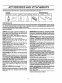
ACCESSORI
A
ATTACHMENTS
These accessories and attachments were available throughmost Sears retailoutletsandservice centers when the tractorwas purchased.
Most Sears stores can order these items for you when you provide the model number of your tractor°
ENGINE
SPARK PLUG
MAINTENANCE
GAS CAN
ENGINEOIL
BLADES
BELTS
PERFORMANCE
Sears offers a wide variety of attachments that fit your tractor. Many ofthese are listed below with brief explanations of how they can help
your This list was current at the time of publication;however, it may change in future years - more attachments may be added, changes
may be made in these attachments, or some may no longer be available or fit your model. Contact your nearest Sears store for the
accessories and attachments that are available for your tractor.
Most of these attachments do not require additional hitches or conversion kits (those that do are indicated) and are designed for easy
attaching and detaching,
SNOW BLADE forsnow removal only. 14-inch high, 48-inch wide
blade clears 42-inch path when angled left or right, Raises, lowers
with side lever° Adjustable skids; replaceable, reversible scraper
bar. (Use with tire chains and wheet welghts and/or rear drawbar
weight.)
SNOWTHROWER has 40-inch swath. Drum-type auger handles
powdery and wet/heavy snow. Mounts easily with simple pin
arrangement, Discharge chute adjusts from tractor seat, 6*inch
diameter spout discharges snow 10 to 50 feet. Lift controlled at
tractor seat. (Use with chains and wheel weights and/or rear
drawbar weight.)
SPRAYERS use 12-volt DC electric motor that connects to the
tractor battery or other 12.volt soumeo Includes booms for
automatic sprayingand hand held wand for spot sl_raying. Wand
has adjustable spray pattemo For applying herbicides, insecticides, fungicides and liquid fertilizers.
SPREADER/SEEDERS make seeding, fertilizing, and weed killing easy. Broadcast spreaders are also useful for granular deicers and sand.
AERATOR promotes deep root growth for a healthy lawn,, Tapered 2,5-inch steel spikes mounted on 10-inch diameter discs
puncture holes in soil at close intervals to let moisture soak in.
Steel weight tray for increased penetration.
BAGGER lets you collect grass clippings and leaves for a
healthier, nearer looking lawn_ Two Permanex containers hold
30-gallon plastic bags°
BUMPER protects front end of tractor from damage,
CARTS make hauling easy° Variety of sizes available, plus
accessories such as side panel kits, tool caddy, cart cover,
protective mat and dolly,,
CORING AERATOR takes small plugs out of soil to allow moisture and nutrients to reach grass roots, 36-inch swath_ 24
hardened steel coring tips. 150 lb.,capacity weight tray,
EASY OIL DRAIN VALVE makes oil changes easier, faster,,
FRONT NOSE ROLLER canters in front of mower deck to reduce
chances of "scalping" on uneven terrain.
GANG HITCH lets you tow 2 or 3 pull-behind attachments at once,
such as sweepers, dethatchers, aerators (not for use with rollers,
carts or other heavy attachments)°
GAUGE WHEELS on both sldes of the mower deck reduce
chances of "scalping" on uneven terrain. For mower decks not so
equipped.
MULCH RAKE/DETHATCHER loosenssoil and flips thatch and
matted leaves to lawn surface for easy pickup_Twenty springline
teeth. Useful to prepare bare areas forseeding, Available for front
or rear mounting. HIGH PERFORMANCE REEL-ACTION
SPRING TINE DETHATCHER covers 36-inch wide path and
tosses thatch into large hopper_ Mounts behind tractor.
MULCHING CLOSE-OUT PLATE KIT, once installed, lets you
mulch, discharge or bag clippings (bagger optional) without
changing blades. For models not equipped as 3-1n-1Convertible
mowers, See "MOWER" in the Repair Parts section of this
manual.
SWEEPERS let you collect grass clippings and leaves,
TILLER has 5 hp engine and 36-inch swath toprepare seed beds,
cultivate and compost garden residue, Tiller has its own bullFln
liftand depth controlsystem anddoes NOT require a sleeve hitch,
Fitsany lawn, yard or garden tractor. Simplyhookup tothe tractor
drawbar and gol Optional accessories
convert unit for
dethatching, aerating, htlllng_oowithout
tools,
TIRE CHAINS are heavy duty; closely spaced extra-large cross
links give smooth ride, outstanding traction°
TRACTOR CAB has heavy duty vinyl fabric over tubular steel
frame, ABS plastictop; clear plastic windshield offers 360 degree
visibility° Hinged metal doors with catch. Keeps operator warm
and dry. Remove vinyl sides and windshields for use as sun
protector in summer_ Optional accessories include: tinted/
tempered solidsafety glass windshield with hand operated wiper;
12_volt amber caution light for mounting on cab top.
VACS for powerfulcollectionof heavy grassclippings and leaves,
Optional wand attachment to pick up debris in hard-to-reach
places. VACtCHIPPER includes a chipper-shredder.
WEIGHT BRACKET for drawbar for snow removal applications.
Uses (1) 55 Ib,,weight°
WHEEL WEIGHTS for rear wheels provide needed traction for
snow removal or dozing heavy materials,,
RAMP TOPS AND FEET let you load and unload tractor from a
pickup truck. Use with 2 x 8 or 2 x 10 lumber_
ROLLER for smoother lawn surface. 36-Inch wide, 18-tnch
diameterwater-tight drum holds up to390 Ibs. of weight. Rounded
edges prevent harm to tuff. Adjustable scraper automatically
cleans drum.
5
CONTENTS
......................................
OF
i,illllllll
Parts Bag contents
i
PACK
, ii ,111
shown full size
Parts packed separately
III
I1'1'1'111111111 iljllll
in carton
iiiiii,
iii
'1'
Seat
II
II
_
....
Mulcher
Plate
Steedng
Wheel
(1) Locknut
5/16-18
(1) Hex Bolt 5/16-18 x 1-1/4
iii1,11111111
I"
I i
,
I
i
II i1,1111'11,1'1'1'1
Video
Cassette
..........
L::
(1) Shoulder Bolt 5/16-18
•
,,,,
Parts Bag
(1) Hex Bolt
1/2-13 x 1
(1) Washer
17/32 x 1-3/16
x 12 Gauge
_Jl_lillltlliillll|qlf
-/'_-_,
(
O
_,%1,.__,,./
1
I
I
1) Lock Washer
1/2
O
iiiiiiii
I1'11'1'
Illll
IHll[
I
J[I
I I
1/11
j'_
_
i,i
III
LlJlJ'IIII
III
IIIUILI
JJlJ/lllll
'1111111111111
(2)
Gauge
Wheels
@
(2)lock
CenterNuts
Steering
Extension
Shaft
(2) Lock Washers #t0
)3116x314xt6Gauge
,
not shown full size
x(2)7/8
x 14 Gauge
Washers
3t8
(2) Shoulder'
Bolts
(2) Washers
"111'1111111111
Parts bag contents
I
Steering Wheel
Adapter
(2) Weld Nuts #10
0
...... ........
@
Steering
Boot
(2) Hex Bolts 1/4-20 x 3/4
(2) Hex Nuts 1/4-20
(2) Keys
(2) Washers
9/32 x 5/8 x 16 Gauge
Steering
Wheel
Insert
_.
(2) Lock Washers 1/4
Slope Sheet
I1'
6
iii
Assemblys
ASSEMBLY
Your new tractor has been assembled at the factory with exception of those parts left unassembled for shipping purposes,
To ensure safe and proper operation of your tractor all parts and hardware you assemble must be tightened securely. Use
the correct tools as necessary to insure proper tightness°
TOOLS REQUIRED
FOR ASSEMBLY
A socket wrench set will make assembly easier° Standard
wrench sizes are listed.
(1) 3/4" Socket w/drive rachet
(2) 7/'16" wrenches
Phillips Screwdriver
(2) 1/2" wrench
Tire pressure gauge
(1) 9/16" wrench
Utilibj knife
When right or left hand is mentioned in this manual, it
means when you are in the operating position (seated
behind the steering wheel).
TO REMOVE TRACTOR FROM CARTON
UNPACK
•
=
•
WHEEL
CARTON
STEERING
BOOT
Remove all accessible loose parts and parts cartons
from carton (See page 6).
Cut, from top to bottom, along lines on all four corners
of carton, and lay panels flaL
Check for any additional loose parts or cartons and
remove.
BEFORE
ROLLUNG TRACTOR
ATTACH STEERING
ADAPTER
OFF SKID
..I
WHEEL (See Fig. 1)
EXTENSION SHAFT
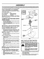
ASSEMBLE EXTENSION SHAFT AND BOOT
°
Slide extension shaft onto lower steering shaft. Align
mounting holes in extension and lower shafts and
install 5/16 hex bolt and locknuL Tighten securely°
IMPORTANT: TIGHTEN BOLT AND NUT SECURELY TO
t8-22 FT. LBS TORQUE,
5/16 HEX BOLT
5/16 LOCKNUT "_
/._'_
_-_
_..
I
°
Place tabs of steering boot over tab slots in dash and
push down to secure°
INSTALL STEERING WHEEL
•
Positionfront wheels of the tractorso they are pointing
straight forward.
•
Slide steering wheel adapter ontosteering shaft extenslono
•
Position steering wheel so cross bars are horizontal
(left to right) andslide inside boot and onto adapter.
Assemble large flat washer, 3/8 lock washer, 3/8 hex
bolt and tighten securely.
°
STEERING
SHAFT
\
_1
_I_i
/_/
r
_
/
FIG. 1
HOW TO SET UP YOUR TRACTOR
CONNECT
I I I I I
°
"_ _._.,
I
!
III
BATTERY
I
iii1,11
'1'1IIIUIL_L
(See Figs. 2 and 3)
i
Snap steering wheel insert into center of steering
wheel.
CAUTION: Do not short battery termi-
Remove protective materials from tractor hood and
grill.
IMPORTANT: CHECK FOR AND REMOVE ANY STAPLES
IN SKID THAT MAY PUNCTURE TIRES WHERE TRACTOR
IS TO ROLL OFF SKIDo
object to contact both terminals at the
nals
allowing
a wrench
or any
other
sameby
time.
Before
connecting
battery,
remove metal bracelets, wristwatch
bands, rings, etc.
°
TO ROLL TRACTOR
,
°
°
°
°
Positive terminal must be connected
first to prevent sparking from accidental grounding.
OFF SKID (See Fig. 8)
Raise attachment lift lever to its highest positionr
Release parking brake by depressing clutch!brake
pedal°
Place gearshift lever in neutral (N) position_
Roll tractor backwards off skid°
Remove banding holding discharge guard up against
tractor.
°
°
°
°
7
Remove carboard packing from seat pan and lift seat
pan to raised position.
Open battery box door.
Be sure battery drain tube is attached to battery box_
Remove terminal protective caps and discard_
_jl,/llljllll
ii
iii i,,
,ll,
ii illll
1,1,1,11 ,i
ii iiilllllll
i
........
ASSEMBLY
i iill ii
ii i
If this battery is put into service after month and year
indicated on label (label located between terminals)
charge battery for minimum of one hour at 6-10 amps.
•
Firstconnect RED battery cable to positive(+) temfinal
with hex bolt, flat washer, lock washer and hex nut as
shown. Tighten securely.
•
Connect BLACK grounding cable to negative (-) terminal with remaining hex bolt, flat washer, lock washer
and hex nut. Tighten securely.
•
Close battery box door.
Open battery box door for:
•
Inspection for secure connections (to tighten hardware).
•
Inspection for corrosion,
•
Testing battery.
•
Jumping (if required)_
°
Periodic charging
i Ill
I
I ,I,
lllllL lull,H,I
•
SEAT PAN
_
ME,T=' _
_-
Y'_,
tl {
LOCKWAS.E.
FIG. 4
CHECK TIRE PRESSURE
,_oTDISCARD
!
!
!
TERMINAL
ECTIVE CAPS
NEX
LOCK
NUT
WASHER
The tires on your tractor'wereoverinflated at the factory for
shipping purposes. Correct tire pressure is important for
best cutting performance.
•
FLAT
WASHER
Reduce tire pressure to PSI shown in "PRODUCT
SPECIFICATIONS on page 3 of this manual,
CHECK DECK LEVELNESS
HEX
BOL_r
For best cutting results, mower housing should be properly
leveled. See "TO LEVEL MOWER HOUSING in the
Service and Adjustments section of this manual.
CHECK
POSITIVE
(RED) CABLE
NEGATIVE
(BLACK) CABLE
FIG,
FOR PROPER
POSITION
OF ALL
See the figures that are shown for replacing motion and
mower blade drive belts in the Service and Adjustments
section of this manual Verify that the belts are routed
correctly.
2
CHECK BRAKE SYSTEM
After you learn how to operate your tractor, check to see
that the brake is properly adjusted. See "TO ADJUST
BRAKE" in the Service and Adjustments section of this
manual.
SEAT
PAN
BATTERY
BOX DOOR
ASSEMBLE
GAUGE
DECK (See Fig. 5)
WHEELS
TO
MOWER
The gauge wheels are designed to keep the mower deck in
proper position when operating mower, Be sure they are
properly adjusted to ensure optimum mower performance,
FIG. 3
•
Adjust mower to desired cutting height (See "TO ADJUST MOWER CUTTING HEIGHT' in the Operation
section of this manual)°
°
With mower in desired height of cut position, gauge
wheels should be assembled so they are slightly off the
ground. Instatt gauge wheel in appropriate hole with
shoulder bolt, 3/8' washer and 3/8-16 Iocknut and
tighten securely.
_Repeat for opposite side installing gauge wheel in
same adjustment hole.
INSTALL SEAT (See Fig. 4)
Adjust seat before tightening adjustment bolto
•
Remove cardboard packing on seat pan_
•
Place seat on seat pan and assemble shoulder bolt.
•
Assemble adjustment bolt,{ockwasherandfiatwasher
loosely. Do not tighten.
°
Tighten shoulder bolt securely,,
°
Lower seat into operating position and sit on seat.
°
Slide seat until a comfortable position is reached which
allows you to press clutch/brake pedal all the way
down.
•
Get off seat without moving its adjusted position_
°
Raise seat and tighten adjustment bolt securely_
°
8
ASS
BLY
TO CONVERT TO BAGGING
DISCHARGING
GAUGE WHEEL
MOUNTING
BRACKET
\
OR
Simply remove mulcher plate and store in a safe place.
Your mower is now ready for discharging or installation of
optional grass catcher accessory°
DEFLECTOR
3/8-16
LOCKNUT
3/8" WASHER
SHOULDER BOLT
GAUGE WHEEL'
FIG. 5
INSTALL MULCHER
(See Figs. 6 & 7)
.
PLATE
Install two latch hooks to mulcher plate using screw,
washer, lock washer, and weld nut as shown,,
LATCH
HOOKS
NOTE: Pre-assemble weld nut to latch hook by inserting
weld nut from the top with hook pointingdown.
•
=
Tighten hardware securely.
Raise and hold deflector shield in upright position_
.
=
Place front of mulcher plate over front of mower deck
opening and slide into place, as shown_
Hook front latch into hole on front of mower deck°
°
Hook rear latch into hole on back of mower deck.
FIG. 7
•/ CHECKLIST
BEFORE YOU OPERATE AND ENJOY YOUR NEW
TRACTOR, WE WISH TO ASSURE THAT YOU RECEIVE
THEBESTPERFORMANCEAND SA TISFA CTION FROM
THIS QUALITY PRODUCT.
PLEASE REVIEW THE FOLLOWING CHECKLIST:
guard from mower. Raise and hold
guard
whenDoattaching
mulcher
plate
CAUTION:
not remove
discharge
and allow it to rest on plate while in
operation.
,/
,/
A!l assembly instructions have been completed.
No remaining loose parts in carton.
/
Battery is properly prepared and charged. (Minimum
1 hour at 6 amps).
Seat is adjusted comfortably and tightened securely.
i ,11,,i
....................
,/
WELD NUT FROM THE TOP
WELD
NUT_\
HOOK POINTS DOWN
J
All tires are propedy inflated. (For shipping purposes,
the tires were overinflated at the factory).
,/
Be sure mower deck is properly leveled side-to-side/
front-to-rear for best cutting results. (Tires must be
properly inflated for leveling)_
,/
Check mower and drive belts. Be surethey are routed
properly around pulleys and inside all belt keepers.
/
Check widng_ See that all connections are still secure
and wires are properly clamped.
LOCK
WASHER
SCREW
LATCH
LATCH
HOOK
WHILE LEARNING HOWTO USE YOUR TRACTOR, PAY
EXTRA A TTENTION TO THE FOLLOWING IMPORTANT
ITEMS:
WELD
,/
Engine oil is at proper level.
#"
Fuel tank is filled with fresh, clean, regular unleaded
gasoline.
Become familiar with all controls - their location and
function. Operate them before you start the engine.
Be sure brake system is in safe operating condition.
NUT
LOCK
WASHER
WASHER
,/
WASHER
MULCHER
PLATE
'_'_SCREW
#'
FIG. 6
9
..................................................................
• .......................
, LI"
I
OPERATION
.................................
,
,,,,H
,H,HH,
..................................
These symbols may appear on your tractor or in literature supplied with the product. Learn and understand their meaning_
A
t
BATTERY
CAUTION OR
WARNING
REVERSE
FORWARD
FAST
SLOW
ENGINE ON
ENGINE OFF
OIL PRESSURE
CLUTCH
LIGHTS ON
LIGHTS OFF
DIFFERENTIAL
LOCK
PARKING BRAKE
LOCKED
UNLOCKED
I
FUEL
!
MOWER LIFT
CHOKE
REVERSE
MOWER HEIGHT
N
H
L
NEUTRAL
HIGH
LOW
ATTACHMENT
CLUTCH ENGAGED
ATTACHMENT
CLUTCH DISENGAGED
c®:>
PARKING BRAKE
IGNITION
HYDROSTATIC FREE WHEEL
(Hydro Models only)
DANGER, KEEP HANDS AND FEET AWAY
10
OPERATION
i......................
::::1,1
,, ,
KNOW YOUR TRACTOR
READ THIS OWNER'S
MANUAL AND SAFETY RULES BEFORE OPERATING
YOUR TRACTOR
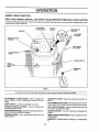
Compare the illustrationswith yourtractortofamiliarize yourselfwiththe locationsofvarious controisand adjustments_ Save
this manual for future reference°
ATTACHMENT
CLUTCH LEVER
IGNITION
SWITCH
AMMETER
LIGHT SWITCH
POSITION
LIFT LEVER
PLUNGER
%
THROTTLE/CHOKE
CONTROL
©
ATTACHMENT
LIFT LEVER
CLUTCH/BRAKE
PEDAL
PARKING BRAKE
HEIGHT
ADJUSTMENT
KNOB
GEARSHIFT
LEVER
FIG. 8
Our tractorsconform to the safety standards of the American National Standards ]nstitute_
ATTACHMENT CLUTCH LEVER: Used to engage the
mower blades, or other attachments mounted to your
tractor°
GEARSHIFT LEVER: Selects the speed and direction of
tractor,
ATTACHMENT LIFT LEVER: Used to raise and lower the
mower deck or other attachments mounted to yourtractor,
LIFT LEVER PLUNGER: Used to release attachment lift
lever when changing its position°
IGNITION SWITCH: Used for starting and stopping the
engine.
HEIGHTADJUSTMENT KNOB: Usedto adjustthe mower
cutting height.
LIGHT SWITCH: Turns the headlights on and off,
THROTTLE/CHOKE CONTROL: Used for starting and
controllingengine speed.
CLUTCH/BRAKE PEDAL: Used for declutching and brakingthe tractor and starting the engine.
PARKING BRAKE: Locks clutch/brake pedal into the
brake position.
AMMETER: Indicates battery charging (÷) or discharging
(-).
'11
ill
.....................
i i ill
IUUlll
......................................
OPERATION
.......
i ..................................................
[111111111
IIIIII
[
The operation of any tractor can result in foreign objects thrown into the eyes, which can
result in severe eye damage. Always wear safety glasses or eye shields while operating your
tractor or performing any adjustments or repairs. We recommend a wide vision safety mask
over the spectacles or standard safety glasses.
NOTE: Under certain conditionswhen tractor is standing
idlewiththe engine running,hot engine exhaust gases may
cause "browning" of grass. To eliminate this possibility,
always stop engine when stopping tractor'on grass areas.
HOW TO USE YOUR TRACTOR
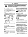
TO SET PARKING
BRAKE (See Fig. 9)
Your tractor is equipped with an operatorpresence sensing
switch, When engine is running, any attempt by the
operator' to leave the seat without first setting the parking
brake will shut off the engine_
•
'"'_ _II L
•
a
Depress clutch/brake pedal into full "BRAKE" position
and hold,
Place parking brake lever in "ENGAGED" position and
release pressure from clutctvbrakepedal. Pedalshould
remain in "BRAKE" position. Make sure parkingbrake
will hold tractor secure.
ATTACHMENT
THROTTLE/
CHOKE
r_n_T=nl
_
"ENGAGED"
/
/
CAUTION:
Always stop tractor
TO USE THROTTLE
-I
V /
',-\\\
/
•
CLUTCH LEVER
°
POSITION
,
,,
'DISENGAGED
ENGAGED
(See Fig. 9)
Operating engine at less than full throttle reduces the
battery charging rate.
Full throttle offers the best bagging and mower performance,
GEARS.,
AND BACKWARD
The direction and speed of movement is controlled by the
gearshift Ievero
°
°
Start tractor' with clutch/brake pedal depressed and
gearshift lever in neutral (N) position.
Move gearshift and range shift levers to desired position_,
,
Slowly release clutch/brake pedal to start movemenL
IMPORTANT:
BRING TRACTOR TO A COMPLETE STOP
BEFORE SHIFTING OR CHANGING GEARS. FAILURE
TO DO SO WILL SHORTEN THE USEFUL LIFE OF YOUR
TRANSAXLE_
_GED"
/
.osmoN
CLUTC.
.AKE
PEDAL
"DRIVE"
POSmON HEIG.T
ADJUSTMENT
KNOB
FIG. 9
STOPPING
CONTROL
Always operate engine at full throttle.
TO MOVE FORWARD
(See Fig. 9)
'
€0m-
pletely, as describedabove, beforeleaving the operator s position; to empty
grass catcher, etc.
..
TO ADJUST MOWER CUTTING
(See Fig. 9)
(See Fig. 9)
HEIGHT
MOWER BLADES -
The cuttingheight is controlledby turningthe height adjustment knob in desired direction,
•
•
Turn knob clockwise (fN)
GROUND DRIVE -
•
Turn knob counterclockwise (_)to
height,
°
The cutting height range is approximately t-1/2" to 4". The
heights are measured from the ground to the blade tip with
the engine not running. These heights are approximate
and may vary depending upon soil conditions, height of
grass and types of grass being mowed.
Move attachment clutch lever to "DISENGAGED" position.
Depress clutch/brake pedal intofuII"BRAKE" position.
•
Move gearshift lever to neutral (N) position.
ENGINE = Move throttle control to slow position.
NOTE: Failure to move throttle controlto slow positionand
allowing engine to idle before stopping may cause engine
to "backfire"°
°
°
Turn ignition key to "OFF" position and remove key,
Always remove key when leaving tractor to prevent
unauthorized use.
Never use choke to stop engine.
12
to raise cutting height.
lower cutting
•
The average lawn should be cutto approximately 2-i t2
inches during the cool season and to over 3 inches
during hot months. For healthier and better looking
lawns, mow often and after moderate growth.
•
For best cutting performance, grass over 6 inches in
height should be mowed twice. Make the first cut
relatively high; the second to desired height.
OPERAON
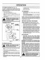
TO OPERATE
MOWER
(See Fig. 10)
°
Your tractor is equipped with an operator presence sensing switch° Any attempt by the operator to leave the seat
with the engine running and the attachment clutch engaged
will shut off the engine°
To restart movement, slowly release parking brake and
clutchforake pedal
°
Make all turns slowly°
.
.
Select desired height of cut.
Lower mower with attachment lift control,
°
Raise attachment lift to highest position with attachment lift control°
•
Start mower blades by engaging attachment clutch
control°
°
When pushingor towing your tractor, be sure gearshift
lever is in neutral (N) position°
•
TO STOP MOWER BLADES _ disengage attachment
clutch control°
°
Do not push or tow tractor at more than five (5) MPH.
!
_I_
A •
!
NOTE: To protect hood from damage when transporting
your tractor on a truck ora trailer, be sure hood is closed and
secured to tractoro Usean appropriate meansoftying hood
to tractor (rope, cord, etc.)o
I
BEFORE STARTING THE ENGINE
..............
CAUTION: DO not operatethe mower .......
without either the entire grass catcher,
I
on mowers So equipped, or the dis|
charge guard in place _.............................
ATTACHMENT CLUTCH LEVER
"DISENGAGED" POSITION
"ENGAGED"
POSITION
TO TRANSPORT
CHECK ENGINE OIL LEVEL (See Fig. 16)
ATTACHMENT
LEVER
HIGH POSI_ON
POSITION
•
°
The engine tnyour tractor has been shipped, from the
factor..,, already filled with summer weight oil.
Check engine oil with tractor on level ground.
•
Remove oil fillcap/dipstick and wipe clean, reinsert the
dipstick and screw cap tight, wait for a few seconds,
remove and read oil level [f necessary, add oil until
"FULL" mark on dipstick is reached. Do not overfill.
°
For cold weather operation you should change oil for
easier starting (See "OiL VISCOSITY CHART" in the
Customer Responsibilities section of this manual).
°
To change engine oil, see the Customer Responsibilities section in this manual.
ADD GASOLINE
°
DISCHARGE
GUARD
FIG. 10
TO OPERATE
ON HILLS
CAUTION: Do not drive up or down
hills with slopes greater than 15° and
do not drive across any slope.
•
Choose the slowest speed before starting up or down
hills.
•
°
Avoid stopping or changing speed on hitls_
If slowing is necessary, move throttle control lever to
slower position.
o
If stopping is absolutely necessary, push clutch/brake
pedal quickly to brake position and engage parking
brake_
•
Move gearshift lever to 1st gear. Be sure you have
allowed room for tractor to roll slightly as you restart
movemenL
13
Fill fuel tank. Use fresh, clean, regular unleaded
gasoline with a minimum of 87 octane° (Use of leaded
gasoline will increase carbon and lead oxide deposits
and reduce valve life). Do not mix oil with gasoline.
Purchase fuel in quantities that can be used within 30
days to assure fuel freshness°
IMPORTANT: WHEN OPERATING IN TEMPERATURES
BELOW 32=F(0°C), USE FRESH, CLEAN WINTER GRADE
GASOLINE TO HELP INSURE GOOD COLD WEATHER
STARTING_
WARNING: Experience indicates that alcohol blended
fuels (called gasohol or using ethanol or methanol) can
attract moisture which leads to separation and formation of
acids during storage. Acidic gas can damage the fuel
system of an engine while in storage. To avoid engine
problems, the fuel system should be emptied before storage of 30 days or longer. Drain the gas tank, start the
engine and let it run until the fuel lines and carburetor are
empty. Use fresh fuel next season_ See Storage Instructions for additional information.
Never use engine or
carburetor cleaner products in the fuel tank or permanent
damage may occur.
i&
CAUTION: Fill to bottom of gas tank
filler neck. Do not overfill. Wipe off any
spilled oil or fuel. Do not store, spill or
use gasoline near an open flame.
........................
iiiiiiiiiiiiiiiiiiii
LL LII
II
II[IIIIIIIIIII
OPERATION
i m,,,,,,,,,,,,,,,,,,
iii tNI
:
"
.......................
' '"'"'
TO START ENGINE (See Fig, 9)
•
When starting the engine for the first time or if the engine
has runout of fuel, it will take extra cranking time to move
fuel from the tank to the engine,
•
•
Sit on seat in operating position, depress clutch/brake
pedal and set parking brake.
.
Place gear shift lever in neutral (N) position.
•
Move attachment" clutch to "DISENGAGED" position.
•
Move throttle control to choke position.
Note: Before starting, read the warm and cold starting
procedures below.
•
lnsert keyinto ignition and rum keyclockwise to"START"
position and release key as soon as engine starts. Do
not run starter continuously for more than fifteen seconds per minute° if the engine does not start after
several attempts, move throttle control to fast position,
wait afew minutes and try again. If engine still does not
start, move the throttle control back to the choke
position and retry.
WARM WEATHER STARTING (50° F and above)
•
When engine starts, movethe throttle control to the fast
position.
.
The attachments and ground drive can now be used. if
the engine does not accept the load, restart the engine
and allow itto warm up for one minute using the cf}oke
as described above.
COLD WEATHER STARTING ( 50 ° F and below)
•
When engine starts, allow engine to run with thethrottle
control in the choke position until the en_lne runs
rougtfly, then move throttle control to fast position. This
may require an engine warm-up period from several
seconds to several minutes, depending on the temperature.
•
The attachments can also be used dudng the engine
warm-up period°
NOTE: if at a high altitude (above 3000 feet) or in cold
temperatures (below 32 F) the carburetor fuel mixture may
need to be adjusted for best engine performance. See "TO
ADJUST CARBURETOR" in the Service and Adjustments
section of this manual+
•
t
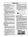
MULCHING
•
Avoid cutting your lawn when itiswet. Wet grass tends
to form clumps and interferes with the mulching action.
The best time to mow your lawn is the early afternoon.
At this time the grass has dried arid the newly cut area
will riot be exposed to the direct sun+
°
For best results, adjust the mower cutting height so that
the mower cuts offonly the top one-third of the grass
blades (See Fig. 12). For extremely heavy mulching,
reduce your width of cut and mow slowly+
Certain types of grass and grass conditions may require that an area be mulched a second time to com+
pletely hide the clippings. Wt_en doing a second cut,
mow across or perpendicular to the first cut path.
•
If grass is extremely tall, it should be mowed twice to
reduce load and possible fire hazard from dried clippings. Make first cut relatively high; the second to the
14
desired heighL
MOWING TIPS
The special mulching blade will recut the grass clippings many times and reduce them in size so that as
they fall onto the lawn they will disperse into the grass
and not be noticed. Also, the mulched grass will
biodegrade quickly to provide nutrients for the lawn.
Always mulch with your highest engine (blade) speed
as this will provide the best recurring action of the
blades+
Mower should be properly leveled for best mow!,n.,g
performance, See 'TO I.EVELMOWER HOUSING in
the Service and Adjustments section of this manual.
The left hand side of mower should be used for trimming.
•
"JJ
•
.
When mowin_ large areas, start by tuming to the right
so that clipplngs will discnarge away from shrubs,
fences, driveways, etc. After one or' two rounds, mow
in the opposite direction making left hand turns until
finished (See Fig, 11 ).
.... ",-
IMPORTANT:
FOR BEST PERFORMANCE, KEEP
MOWER HOUSING FREE OF BUILT-UP GRASS AND
TRASH+ CLEAN AFTER EACH USE.
•
•
IL
FIG. 11
Tire chains cannot be used when the mower housing is
attached to tractor.
Ddve so that clippings are discharged onto the area
that has been cut. Have the cut area to the right of the
tractor. This will result in a more even distribution of
clippings and more uniform cutting.
When operating attachments, select a ground speed
that will suit the terrain and give best performance of
the attachment being used.
1
.
°
NNI
Do not mow grass when it is wet. Wet grass will plug
mower and leave urldesirable clumps, Allow grass to
dry before mowing.
Always operate engine at full throttle when mowing to
assure better mowing performance and proper discharge of material. Regulate ground speed by selecting a low enough gear to give the mower cutting
performance as welt as the quality of cut desired.
[
MOWINGTIPS
•
.............
Change your cutting pattern from week to week. Mow
north to south one week then change to east to west the
next week. This will help prevent matting and graining
of the lawn.
MAX 1/3
FIG. 12
CUSTOM
MAINTENANCE
SCHEDULE
FILL IN DATES
AS YOU COMPLETE
R EGULAR SERV!CE
L
ESPO
.,f___
ES
_._o__
/_X_'_._<p_"_.
/_-_,_/_O_
_'_0
7
/_/_'_ERVICE
Check Brake Operation
_/
_/
_
$/
DATES
=
Check Tire Pressure
T Check_er"Le'ose'Fasteners
,
t_/
X
C
....
,
_,
V'
,_
..................................
.............
T
Cheek Ba}},e,ry 'Leve!/Recharge
0
Clean Battery and Terminals
Q##
R
Check Transaxle Cooling
_
.....
_/
'
.....
A ju tB deBeit(s)
Tens o" .........
KS'
Adjust Motion Drive Belt(e) Tension
_/
_#'
Change Engine OIl
Clean Air Filter
N
G
Clean Air Screen
,
_#'s
Check Engine Oil Level
E
,
_,,3
_/'2
_
_f2
i
:
.
J
Inspect MuffledSparkArrester
Replace Oil Filter(if equipped)
Clean Engine Cooling Fins
Replace Spark Plug
.......
_
|
_
i
i
Replace Air Filter Paper Cartridge
!
i
;:
;
;
, ,,,
,
........ ; .........................
_V#'2
,,,, ..................................
,
,
Replace Fuet Filter
t - Change mote often when operating under a heavy toad or in high ambient temperatures
2 - Sen/Ice more often when operating in dirty or dusty conditions,
3 _If equipped wiih oil filter,change of!every 50 hours.
4 - Repbce blades more often when mowing In sandy soil,,
5 - tf equipped wi_h adjustable system,
6 - Net required If equipped with maintenance-free battery.
7 - Tighten front axle pivot bolt to 35 ft.*lbs m_lxlmum_
Do not ovedJghten.
LUBRICATION
GENERAL RECOMMENDATIONS
The warranty on this tractor does not cover items that have
been subjected to operator abuse or negligence,_ To
receive fullvalue from the warranty, operator must maintain
tractor as instructed in this manual
(_SPINDLE
ZERK--_
(_) FRONT WHEEl;,
BEARING ZERK
Some adjustments will need to be made periodically to
properly maintain your tractor.
CHART
.__F_---SPINDLE
_
_
"=;'_:;'_
I _
ZERK (_)
FRONT WHEEL (_)
BEARING ZERK
|
All adjustments in the Service and Adjustments section of
this manual should be checked at least once each season.
®
Once a year you should replace the spark plug, clean
or replace air filter, and check blades and belts for
wear° A new spark plug and clean air filter assure
proper air-fue! mixture and help your engine run better
and last longer.
BEFORE
@
CLUTCH
PIVOT(S)
EACH USE
o
•
Check engine oil level
Check brake operation,
•
•
Check tire pressure.
Check for loose fasteners..
PIVOTS
15
(_
SAE 30 OR 10W30 MOTOR OIL
®
GENERAL PURPOSE GREASE
®
REFER TO CUSTOMER RESPONSIBILITIES
ENGINE
O
SECTION
IMPORTANT:
DO NOT OIL OR GREASE THE PIVOT POINTS
WHICH HAVE SPECIAL NYLON BEARINGS°
VISCOUS LUBRI*
CANTS WILL ATTRACT DUST AND DiRT THAT WILL SHORTEN
THE LiFE OF THE SELF-LUBRICATING
BEARINGS.
IF YOU
FEEL THEY MUST BE LUBRICATED,
USE ONLY A DRY, POWDERED GRAPHITE TYPE LUBRICANT SPARINGLY,,
.............................
,,,,,,,,,
,,,,
CUSTOMER
.........................
ill llllll,lUUll
iiiill
i,iiiiilll,i
RESPONSIBILITIES
TRACTOR
MANDREL,
BLADE
Always observe safety rules when performingany mainte_
nance,
BRAKE OPERATION
if tractor requires more than six (6) feet stopping distance
at high speed in highest gear, then brake must be adjusted°
(See "TO ADJUST BRAKE" in the Service and Adjustments section of this manual).
TIRES
EDGE
LOCK WASHER
•
Maintain proper air pressure in all tires (See =PRODUCT SPECIFICATIONS" on page 3 of this manuaf)o
•
Keep tires free of gasoline, oil, or insectcontrolchemicals which can harm rubber.
°
Avoid stumps, stones, deep ruts, sharp objects and
other hazards that may cause tire damage.
HEX BOLT
*A GRADE 8 HEAT TREATED BOLT CAN BE
IDENTIRED BY SIX LINES ON THE BOLT HEAD.
FIG. 13
NOTE; To seal tire punctures and prevent flat tires due to
slow leaks, tire sealant may be purchased from your local
parts dealer_ Tire sealant also prevents tire dryrot and
corrosion.
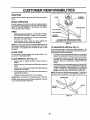
TO SHARPEN
For best results mower blades must be kept sharp° Replace bent or damaged blades.
(See Fig. 13)
•
Raise mower to highest position to allow access to
blades,
°
Remove hex bolt, iockwasherandflatwashersecudng
blade,
°
Install new or resharpened blade with trailing edge up
towards deck as shown,
°
Reassemble hex bolt, lock washer and flat washer in
exact order as shown°
BLADE (See Fig. 14)
Care should be taken to keep the blade balanced. An
unbalanced blade willcause excessive vibration and eventual damage to mower and engine.
° The blade can be sharpened with a file or on a gdnding
wheel Do not attempt to sharpen while on the mower.
° To check blade balance, you will need a 5/8" diameter
steel bolt, pin, or acone balancer. (When using a cone
balancer, follow the instructions supplied with balancer)..
Slide blade on to an unthreaded portion of the steel bolt
or pin and hold the bolt or pin parallel with the ground.
If blade is balanced, it should remain in a horizontal
position. If either end of the blade moves downward,
sharpen the heavy end until the blade is balanced,
NOTE: Do not use a nail for balancing blade. The lobes of
the center hole may appear to be centered, but are not.
BLADE CARE
BLADE REMOVAL
TRAIUNG
FLAT __\
o Tighten bolt securely (30-35 Ft. Lbs. torque),
IMPORTANT: BLADE BOLT IS GRADE 8 HEATTREATED.
CENTER HOLE
NOTE: We do not recommend sharpening blade- but ifyou
do, be sure the blade is balanced.
FIG. 14
16
/
/
BATTERY
NOTE: Although multi-viscosity oils (5W30, 10W30 etc.)
improve starting in cold weather, these multi-viscosity oils
wilt result in increased oil consumption when used above
32°F. Check your engine oil level more frequently to avoid
possible engine damage from running low on clio
Your tractor has a battery charging system which is sufficient for normal use, However, periodic charging of the
battery with an automotive charger will extend its life.
•
Keep battery and terminals clean_
•
o
Keep battery bolts tight.
Keep small vent holes open,
Change the oil after every 25 hours of operation or at least
once a year ifthe tractor is not used for 25 hours in one year°
Check the crankcase oil level before starting the engine
and after each eight (8) hours of operation. Tighten oil fill
cap/dipstick securely each time you check the oil level.
•
Recharge at 6o10 amperes for I hour°
TO CLEAN BATTERY AND TERMINALS
TO CHANGE ENGINE OIL (See Figs° 15 and 16)
Corrosion and dirt on the battery and terminals can cause
the battery to "leak" power_
Open battery box door.
Determine temperature range expected before oil change,
All oil must meet API service classification SF, SG or SH.
°
Be sure tractor is on level surface.
o
Disconnect BLACK battery cable first then RED battery cable and remove battery from tractor.
°
Rinse the battery with plain water and dry°
.
Clean terminals and battery cable ends with wire brush
until bright°
•
Coat terminals with grease or petroleum jelly.
=
°
Reinstall battery (See "CONNECT BATTERY" in the
Assembly section of this manual)oV-BELTS
°
After oil has drained completely, replace oil drain plug
and tighten securely.
Check V-belts for deterioration and wear after 100 hours of
operation and replace if necessary. The belts are not
adjustabTeoReplace belts if they begin to slip from wear.
°
Refill engine with oil through oil fill dipstick tube. Pour
slowly. Do not overfill. For approximate capacity see
"PRODUCT SPECIFICATIONS" on page 3 of this
manual.
°
Use gauge on oil fill cap/dipstick for checking level° Be
sure dipstick cap is t=ghtenedsecurely for accurate
reading. Keep oil at "FULL" line on dipstick.
TRANSAXLE
COOLING
Keep transaxle free from build-up of dirt and chaff which
can restrict cooling,
°
•
Oil will drain more freely when warm.
Catch oil in a suitable container.
=
Remove oil fill cap/dipstick, Be careful not to allow dirt
to enter the engine when changing oil,
Remove drain plug.
ENGINE
LUBRICATION
FILL
CAP/DIPSTICK
Only use high quality detergent oil rated with API service
classification SF, SG or SH. Select the oil's SAE viscosity
grade according to your expected operating temperature.
SAE VISCOSITY GRADES
OIL DRAIN
PLUG
°F
.SO"
o° '........3o° _" 40
°.........._o
eo•
Ioo.
i°c -3oo
-20_
...........
-loo,
oo
Ioo
2o°
3o° 40•
i!EMPERATURE
RANGE ANTICIPATED
BEFORE NEXT OIL CHANGE
FIG. 16
FIG. 15
17
IBILITIES
CUSTOMER
= Ill J lu=lllll=llllu=ll=L=,
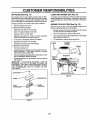
AIR FILTER (See Fig. 17)
CLEAN AIR SCREEN (See Fig. 18)
Your engine will not run properly using a dirty air filter,
Clean the foam pre-cleaner after every 25 hours of operation or every season, Service paper cartridge every 100
hours of operation or every season, whichever occurs first,
Air screen must be kept free of dirt and chaff to prevent
engine damage from overheating, Clean with awire brush
or compressed air' to remove dirt and stubborn dried gum
fibers,
Service air cleaner more often under'dusty conditions.
ENGINE COOLING
•
Remove knob(s) and cover.
TO SERVICE PRE-CLEANER
FINS (See Fig. 18)
Remove any dust, dirt or oil from engine cooling fins to
prevent engine damage from overheating,
.
Remove screws from blower housing and lift housing
and dipstick tube assembly off engine,
°
Slide foam pre-cleaner off cartridge°
°
Wash it in liquid detergent and water,
•
•
Squeeze it dry in a clean cloth°
Saturate it in engine oil, Wrap it in clean, absorbent
cloth and squeeze to remove excess oil,
°
Cover oil fill opening to prevent entry of dirt.
•
Use compressed air or stiff bristle brush to thoroughly
clean engine cooling fins_
•
if very dirty or' damaged, replace pre-cleaner.
•
To reassemble, reverse above procedure.
°
Reinstall pre-cleaner over cartridge°
•
Reinstall cover and secure with knob(s)..
TO SERVICE CARTRIDGE
SCREWS
°
Remove cartridge nut.
°
Carefully remove cartridge to prevent debris from entering carburetor. Clean base carefully to prevent
debris from entering carburetor.
°
Cleancartridgebytappinggentlyonflatsurface.
dirty or damaged, replace cartndgeo
BLOWER
HOUSING
if very
DIPSTICK
TUBE
ASSEMBLY
•
Reinstall cartridge, nut, precleaner, cover and secure
with knob(s).
IMPORTANT:
PETROLEUM SOLVENTS, SUCH AS
KEROSENE, ARE NOT TO BE USED TO CLEAN THE
CARTRIDGE, THEY MAY CAUSE DETERIORATION OF
THE CARTRIDGE. DO NOT OIL CARTRIDGE° DO NOT
USE PRESSURIZED
AIR TO CLEAN OR DRY
CARTRIDGE
PLUG
COVER KNOB
ENGINE COOLING FINS
FIG. 18
COVER
CARTRIDGE NUT
PAPER
CARTRIDGE
FIG. 17
18
CUSTO
: :
,_,
i iI
ESPONSH
pl ,Ulll
i _
,
iiiiii I
iiI i
L L I L
iii
LmTUES
iI ....
MUFFLER
CLAMP
Inspect and replace corroded muffler and spark arrester (if
equipped) as it could create a fire hazard and/or damage.
CLAMP
SPARK PLUGS
Replace spark plugs at the beginning of each mowing
season or after every 100 hours of operation, whichever
occurs first. Spark plug type and gap setting are shown in
"PRODUCT SPECIFICATIONS" on page 3 of this manual,
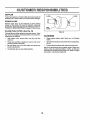
IN-LINE FUEL FILTER
FUEL
FILTER
(See Fig. 19)
FIG. 19
The fuel filter should be replaced once each season,, If fue!
filter becomes clogged, obstructingfuel flow to carburetor,
replacement is required.
°
With engine cool, remove filter and plug fuel line
sections°
o
°
°
CLEANING
Place new fuel filter in position in fuel line with arrow
pointing towards carburetor.
Be sure there are no fuel tine leaks and clamps are
properly positioned.
•
Clean engine, battery, seat, finish, etc, of all foreign
matter.
°
Keep finished surfaces and wheels free of all gasoline,
oil, etc.
•
Protect painted surfaces with automotive type wax.
We do not recommend using a garden hose to clean your
tractor unless the electrical system, muffler, air filter and
carburetor are covered to keep water ouL Water in engine
can result in a shortened engine life.
Immediately wipe up any spilled gasoline.
19
....
ii ii ii ,,llUl,ii
SERVICE AND ADJUSTM
ii i, i,i
...........................
ii iiiiiiiilU
............
I!/IIIIIIIII[IlUI[
,
, i
iiii
CAUTION" BEFORE PERFORMING ANY SERVICE OR ADJUSTMENTS;
O
I
°
°
°
Depress clutch/brake pedal fully and set parking brake,
Place gearshift lever in neutral (N) position.
Place attachment clutch in "DISENGAGED" position.
Turn ignition key "OFF" and remove key.
Make sure the blades and all moving parts have completely stopped.
Disconnect spark plug wire from spark plug and place wire where it cannot come in contact with
plug,
..............
..........................
Illl
TRACTOR
TO REMOVE
MOWER (See Fig. 20)
CLUTCH
Mower willbe easier to remove from the rightsideof tractor.
•
°
Place attachment clutch in "DISENGAGED" position.
Move attachment liftlever forward to lowermower to its
lowest position.
°
°
Roll belt off engine pulley°
Disconnect clutch rod from clutch lever by removing
retainer spring.
Disconnect anti-sway bar from chassis bracket by
removing retainer spdng.
°
RETAINER
SPRANG
°
Disconnect suspension arms from rear deck brackets
by removing retainer springs.
°
Disconnect front links from deck by removing retainer
springs.
°
Raise lift lever to raise suspension arms° Slide mower
out from under tractor:
IMPORTANT:
IF AN ATTACHMENT OTHER THAN THE
MOWER IS TO BE MOUNTED TO THE TRACTOR, THE
R.H. AND L.H. SUSPENSION ARMS MUST BE REMOVED
FROM TRACTOR.
TO INSTALL
RETAINER
SPRING
ANTI-SWAY BAR
(BOTHSIOES)
MOWER (See Fig. 20)
o
°
Raise attachment lift lever to its highest positiono
Slide mower under tractor with discharge guard to right
side of tractor.
°
°
Lower lift lever to its lowest position°
install mower in reverse order of removal instructions°
RETAINER
SPRINGS
FIG. 20
20
iiiii
RVmCE AND ADJUSTMENTS
--
::
,,iH,=l=,,,,tiH===
=.........
lll,i ..............................
,,it,_
.....
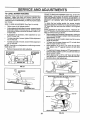
TO LEVEL MOWER HOUSING
FRONT-TO*BACK ADJUSTMENT (See Figs° 23 and 24)
IMPORTANT; DECK MUST BE LEVEL SIDE-TO-SIDEo IF
THE FOLLOWING FRONT-TO-BACK ADJUSTMENT IS
NECESSARY, BE SURE TO ADJUST BOTH FRONT LINKS
EQUALLY SO MOWER WILL STAY LEVEL SIDE-TOSIDE.
Adjust the mower while tractoris parked on level ground or
driveway.
Make sure tires are properly inflated (See
"PRODUCT SPECIFICATIONS" on page 3 of this manual).
If tires are over or underinflated, you will not properly adjust
your mower°
To obtain the best cutting results, the mower housing
should be adjusted so that the front is approximately 1/8" to
1/2" lower than the rear when the mower is in its highest
position.
Check adjustment on right side of tractor, Measure distance"D" directly in front and behind the mandrel at bottom
edge of mower housing as shown.
°
Before making any necessary adjustments, checkthat
both front links are equal in length. Both linksshould be
approximately 10-3/8".
•
If links are not equal in length, adjust one link to same
length as other link.
° To lower front of mower loosen nut "E" on both front
links an equal number of turns.
= When distance "D" is 1/8" to 1/2" lower at front than
rear, tighten nuts "F" against trunnion on both front
links.
•
To raise front of mower, loosen nut"F" from trunnion on
both front links. Tighten nut "E" on both front links an
equal number of turns.
° When distance "D" is 1/8" to 1/2" lower at front than
rear, tighten nut"F" against trunnion on both front links,
°
Recheck side-to-side adjustment.
SIDE-TO-SIDE ADJUSTMENT (See Figs. 21 and 22)
= Raise mower to its highest position.
°
At the midpoint of both sides of mower, measure height
from bottom edge of mower to ground. Distance"A"on
both sides of mower should be the same or within I/4
of each other.
°
If adjustment is necessary, make adjustment on one
side of mower only.
=
To raise one side of mower, tighten lift link adjustment
nut on that side.
o
To lower one side of mower, loosen lift link adjustment
nut on that side.
NOTE: Each full turn of adjustment nut willchange mower
height about 1/8".
o
Recheck measurements after adjusting.
BOTTOM EDGE
OF MOWER TO
GROUND
BOTTOM EDGE
OF MOWER TO
GROUND
GROUND LINE
llll
MANDREL
A
FIG. 21
FIG. 23
BOTH FRONT LINKS MUST BE EQUAL IN LENGTH
LIFT LINK
ADJUSTMENT NUT
FIG. 22
NUT "E"
NUT
FRONT LINKS
21
TRUNNION
FIG. 24
SERVICE AND ADJUSTM
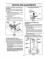
TO REPLACE
(See Fig. 25)
MOWER
BLADE DRIVE BELT
WITHPARKINGBRAKE "ENGAGED"
The mower blade drive belt may be replaced withouttools.
Park the tractor on level surface. Engage parking brake°
BELT REMOVAL *
Remove mower from tractor (See "TO REMOVE
MOWER" in this section of this manual).
NUT "A"
JAM NUT
,
Work belt off both mandrel pulleys and idler pulleys,
°
Pull belt away from mower',
BELT INSTALLATION •
Install new bett in reverse order of removal.
*
Make sure belt isin all pulley grooves and insideall belt
guides°
Install mower in reverse order of removal instructions,
•
OPERATING
ARM
FIG, 26
MANDREL
PULLEY
IDLER
PULLEYS
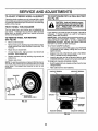
TO REPLACE
(See Fig. 27)
MOTION DRIVE BELT
Park the tractor on level surface. Engage parking brake,
For assistance, there is a belt installation guide decal on
bottom side of left footrest.
MANDREL
PULLEY
Remove mower (See "TO REMOVE MOWER" in this
section of this manual.)
•
Remove upper belt keeper°
•
•
Remove belt from stationary idler and clutching idler,
Pull belt slack toward rear' of tractor° Remove belt
upwards from transaxle pulley by deflecting belt keepers,
•
Pull belt toward front oftractor and remove downwards
from around engine pulley.
•
Install new belt by reversing above procedure,
IMPORTANT; MAKE SURE UPPER BELT KEEPER IS
POSITIONED PROPERLY BETWEEN LOCATOR TABS,
FIG. 25
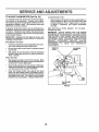
TO ADJUST
•
r
BRAKE (See Fig. 26)
/
Your tractor is equipped with an adjustable brake system
which is mounted on the right side of the transaxle.
!
PULLEY
CLUTCH_NG--...L---'-_._p-'f
If tractor requires more than six (6) feet stopping distance
at high speed in highest gear, then brake mustbe adjusted,
|
•
Depressclutch/brake pedaland engage parkingbrake,
/
STATIONARY_
*
Measure distance between brake operating arm and
nut 'W' on brake rod.
/
TRANSAXLE_
il
/
If distance is otherthan 1-1/2", loosen jam nut and turn
nut "A" until distance becomes 1-112'L Retighten jam
nut against nut "A",
Road test tractor for proper stopping distance as stated
above° Readjust if necessary. If stopping distance is
still greater than six (6) feet in highest gear', further
maintenance is necessary° Contact your nearest authorized service center]department.
j{(
o),_
""_'1
il TASS
|
I r_ UPPER BELT
I
l!
KEEPER
I! II !!
II
_
FIG. 27
22
JI-LoOATOR
!!
SERVICE A D ADJUSTMENTS
TO ADJUST STEERING
TO START ENGINE WITH A WEAK BATTERY
(See Fig. 29)
WHEEL ALIGNMENT
If steering wheel crossbars are not horizontal (leftto right)
when wheels are positioned straight forward, remove steering wheel and reassemble per instructionsin the Assembly
section of this manual.
t
,_
_-]_
FRONT WHEEL TOE-INICAMBER
_1_
The front wheel toe-in and camber are not adjustable on
your tractor, tf damage has occurred to affect the front
wheel toe-in or camber, contact your nearest authorized
service center/department,,
Block up axle securely_
=
Remove axle cover, retaining ringand washers toallow
wheel removal (rear wheel contains a square key - Do
not lose).
=
Repair tire and reassemble.
=
On rear wheels only: align grooves in rear wheel hub
and axle. Insert square key.
°
Replace washers and snap retaining ring securely in
axle groove.
Replace axle cover,_
°
I
|
|
If your battery is too weak to start the engine, it should be
recharged.
If "jumper cables" are used for emergency
starting, follow this procedure:
IMPORTANT: YOUR TRACTOR IS EQUIPPED WITH A 12
VOLT NEGATIVE GROUNDED
SYSTEM,
THE OTHER
VEHICLE
MUST ALSO BE A 12 VOLT
NEGATIVE
GROUNDED SYSTEM.
DO NOT USE YOUR TRACTOR
BATTERY TO START OTHER VEHICLES.
TO REMOVE WHEEL FOR REPAIRS
(See Fig, 28)
.
CAUTION: Lead-acid batteries generate explosive gases. Keep sparks, flame
and smoking materials away from batteries. Always wear eye protection
when around batteries.
TO ATTACH JUMPER CABLES ° Connect each end of the RED cable to the POSITIVE
(+) terminal of each battery, taking care not to short
against chassis.
° Connect one end of the BLACK cable to the NEGATIVE (-) terminal of fully charged battery°
°
Connect the other end of the BLACK cable to good
CHASSIS GROUND, away from fuel tank and battery.
TO REMOVE CABLES, REVERSE ORDER ° BLACK cable first from chassis and then from the fully
charged battery_
•
RED cable last from both battedeso
NOTE: To seal tire punctures and prevent flat tires due to
slow leaks, tire sealant may be purchased from your local
parts dealer° Tire sealant also prevents tire dry' rot and
corrosion.
POSITIVE TERMINAL
NEGATIVE TERMINAL
WASHERS
RETAINING
RING
I
AXLE COVER
"_ SQUARE KEY
(REAR WHEEL ONLY)
CABLES
FIG. 28
CHARGED
BATTERY
POSITIVE TERMINAL
NEGATIVE TERMINAL
FIG. 29
23
SERVICE AND ADJUSTM
TO REPLACE
e
e
Q
HEADLIGHT
BULB
ENGINE
Raise hood.
Pull bulb holder out of the hole in the backside of the
grill°
TO ADJUST THROTTLE
(See Fig. 31)
Replace bulb in holder and push bulb holder securely
back into the hole in the backside of the grill.
Close hood.
The throttle control has been preset at the factory and
adjustment should not be necessary. Check adjustment as
described below before loosening cable. If adjustment is
necessary, proceed as follows:
INTERLOCKS
AND RELAYS
.
Loose or damaged wiring may cause your tractor to run
poorly, stop running, or prevent it from starting.
°
°
Check wiring. See electrical wiring diagram in the
Repair Parts section of this manual.,
TO REPLACE
FUSE
CONTROL
CABLE
With engine not running, move throttle control lever
from slow to choke position. Slowly move lever from
choke to fast position.
Check that holes"A" in governor control lever and hole
in governor plate line-up. If holes "A" are not aligned,
loosen clamp screw and move throttle cable until holes
are aligned. Tighten clamp screw securely,
Replace with 30 amp automotive-type plug-in fuse. The
fuse holder is located behind the dash.
GOVERNOR
CONTROL LEVER
\
GOVERNOR
CONTROL PLATE
TO REMOVE HOOD AND GRILL ASSEMBLY
(See Fig. 30)
•
Raise hood,
•
Unsnap headlight wire connector.
•
Stand in front of tractor, Grasp hood at sides, tilttoward
engine and lift off of tractor.
To replace, reverse above procedures.
•
HOLES "A"
HOOD
CLAMP
SCREW
FIG. 31
HEADLIGHT
WIRE
CONNECTOR
FIG. 30
24
THROTTLE
CABLE
,ll
iiiii ..................
USTMENTS
i
'l'l'l'l'H'll'l 'L_l'_l
II
ll"l"l"
" I
....................
TO ADJUST CARBURETOR (See Fig. 32)
ACCELERATION TEST -
The carburetor has been preset at the factory and adjustmerit should not be necessary. However, minor adjustment may be required to compensate for differences infuel,
temperature, altitude or Ioado If the carburetor does need
adjustment, proceed as follows:
°
tn general, turning idle mixture valve in (clockwise) decreases the supply of fuel to the engine giving a leaner fuel/
air mixture. Turning the idle mixture valve out (counterclockwise) increases the supply of fuel to the engine giving
a richer fuel/air mixture.
High speed stop is factory adjusted.
Do not adjust damage may result.
IMPORTANT:
NEVER TAMPER WITH THE ENGINE
GOVERNOR, WHICH IS FACTORY SET FOR PROPER
ENGINE SPEED. OVERSPEEDING
THE ENGINE ABOVE
THE FACTORY
HIGH
SPEED
SETTING
CAN BE
DANGEROUS.
IF YOU THINK THE ENGINE-GOVERNED
HIGH SPEED NEEDS ADJUSTING,
CONTACT
YOUR
NEAREST
AUTHORIZED
SERVICE
CENTER/
DEPARTMENT, WHICH HAS PROPER EQUIPMENT AND
EXPERIENCE
TO
MAKE
ANY
NECESSARY
ADJUSTMENTS°
IMPORTANT:
DAMAGE TO THE NEEDLE VALVE AND
THE SEAT IN CARBURETOR
MAY RESULT IF SCREW IS
TURNED IN TOO TIGHT,
PRELIMINARY
SETTING
-
o
Air cleaner assembly must be assembled to the carburetor when making carburetor adjustments.
°
Be sure the throttle control cable is adjusted properly
(see above).
° With engine off turn idle mixture valve in (clockwise)
closing it finger tight and then turn out (counterclockwise) ! full turn.
FINAL SETTING
°
Start engine and allow to warm for five minutes. Make
final adjustments with engine running and shift/motion
control lever in neutral (N) position.
=
Move throttle control lever to slow position_ With finger,
rotate and hold throttle lever against idle speed screw°
Turn idle speed screw to attain 1750 RPM.
o
While still holding throttle lever against idle speed
screw, turn idle mixture valve in (clockwise) unttl engine begins to die and then turnout (counterclockwise)
until engine runs rough° Turn valve to a point midway
between those two positions. Release throttle lever.
Move throttle control lever from slow to fast position. If
engine hesitates or dies, turn idle mixture valve out
(counterclockwise)
1/8 turn° Repeat test and continue
to adjust, if necessary,
until engine accelerates
smoothly_
THROTTLE
LEVER
IDLE SPEED
SCREW'
IDLE MIXTURE
VALVE
FIG. 32
25
ENGINE
Immediately prepare your tractor for storage at the end of
the season or if the tractor will not be used for 30 days or
more.
'lqll
!
! _
! _
I
A
• •
::::::
:
FUEL SYSTEM
/'11!
IMPORTANT:
IT IS IMPORTANT
TO PREVENT
GUM
DEPOSITS
FROM FORMING
tN ESSENTIAL
FUEL
SYSTEM PARTS SUCH AS CARBURETOR, FUEL FILTER,
FUEL HOSE, OR TANK DURING STORAGE.
ALSO,
EXPERIENCE
INDICATES THAT ALCOHOL BLENDED
FUELS (CALLED GASOHOL OR USING ETHANOL OR
METHANOL) CAN ATTRACT MOISTURE WHICH LEADS
TO SEPARATION AND FORMATION OF ACIDS DURING
STORAGE.
ACIDIC GAS CAN DAMAGE THE FUEL
SYSTEM OF AN ENGINE WHILE IN STORAGE.
CAUTION: Never storethe tractor with
gasoline in the tank inside a building
where fumes may reach an open flame
or spark. Allow the engine to cool
before storing in any enclosure,
TRACTOR
Remove mower from tractor for winter storage. When
mower' is to be stored for a period of time, clean it thoroughly, remove all dirt, grease, leaves, etc. Store in a
clean, dry area°
•
Clean entiretractor (See"CLEANING"in the Customer
Responsibilities section of this manual).
•
Inspect and replace belts, if necessary (See belt replacement instructions in the Service and Adjustments
section of this manual).
•
Lubricate as shown in the Customer Responsibilities
section of this manual.
•
Be sure that all nuts, bolts and screws are securely
fastened. Inspect moving parts for damage, breakage
and wear. Replace if necessary.
Touch up all rusted or chipped paint surfaces; sand
lightly before painting.
•
*
Drain the fuel tank_
•
Start the engine and let it run until the fuel lines and
carburetor are empty.
•
Never use engine or carburetorcIeaner products in the
fuel tank or permanent damage may occur.
Use fresh fuel next season_
•
NOTE: Fuel stabilizer is an acceptable alternative in
minimizing the formation of fuel gum deposits dudng storage. Add stabilizer to gasoline in fuel tank or storage
container. Always follow the mix ratio found on stabilizer
container'. Run engine at least 10 minutes after adding
stabilizer to allow the stabilizer to reach the carburetor. Do
not drain the gas tank and carburetor if using fuel stabilizer.
ENGINE OIL
BATTERY
Drain oil (withengine,warm) and replace with clean engine
oil. (See "ENGINE' in the Customer Responsibilities
section of this manual).
•
•
CYLINDERS
•
•
Fully charge the battery for storage_
After a period of time in storage, battery may require
recharging°
To help prevent corrosion arid power leakage during
long periods of storage, battery cables should be
disconnected and battery cleaned thoroughly (see _O
CLEAN BATTERY AND TERMINALS in the Customer Responsibilities section of this manual).
After cleaning, leave cables disconnected and place
cables where they cannot come in contact with battery
terminals,
•
Remove spark plug(s).
•
Pour one ounce of oil through spark plug hole(s) into
cylinder(s).
•
Turn ignitionkey to"START" positionfor a few seconds
to distribute oil.
•
Replace with new spark plug(s)=
OTHER
•
Be sure battery drain tube is securely attached_
•
Do not store gasoline from one season to another.
•
if battery is removed from tractor for storage, do not
store battery directly on concrete or damp surfaces.
•
Replace your gasoline can tf your can starts to rust.
Rust and/or dirt in your gasoline will cause problems.
If possible, store your tractor indoors and cover it to
give protection from dust arid dirt.
•
•
Cover your tractor with a suitable protective cover that
does not retain molsture_ Do not use plastic. Plastic
cannot breathe which allows condensation to form and
will cause your' tractor to rust.
IMPORTANT: NEVER COVER TRACTOR WHILE ENGINE
AND EXHAUST AREAS ARE STILL WARM.
26
PROBLEM
CAUSE
Wtll not start
1,, Out of fuel,,
1,,
Fill fuel tank,
2,,
3
4_
5o
6o
7,
Engine not =CHOKED" prope.dy,
Engine f|ooded_
Bad spark plug,
Dirty air filter,,
Dirty fuel filter
Water in fuai_
2.
3,
4,
5,,
6.
7,
8_
9.
Loose or damaged wiring,
Carburetor out of adjustment.
8,
9
See "TO START ENGINE" in Operation section,
Wait several minutes before attempting to start,
Replace spark plug,
Clean/replace air filter,
Replace fuel filter.
Drain fuel tank and carburetor, refill tank with fresh
gasoline and replace fuel filter.,
Check all wiring.
See "To Adjust Carburetor" in Service Adjustments
section.
Contact an authorized service center/department.
10,,
Hard to start
CORRECTION
Engine valves out of adjustment.
1o
2.
3,.
4o
5,
6_
7o
Dirty air filter,
Bad spark plug,,
Weak or dead battery,
Dirty fuel filial
Stale or dirty fuel.
Loose or damaged wiring°
Carburetor out of adjustment,
8,
Engine valves out of adjustment,
1,
2.
3,,
4,,
Clutch/brake pedal not depressed.,
Attachment clutch is engaged,,
Weak or dead battery_
Blown fuse°
5_
6,
7.
8.
9
Engine clicks but wtll not
start
Loss of power
Engine wig not turn over
,llllll,i,
i,ll
Excessive vibration
10,
1o Clean/replace afr rifler,
2, Replace spark p{ug,
3,, Recharge or replace battery,,
4, Replace fuel filter,
5_ Drain fue) tank and refill with fresh gasolineo
6, Check all wiring.
7, See "To Adjust Carburetor" in Service Adjustments
section,
8, Contact an authorized service centar/department_
Corroded battery terminals.,
Loose or damaged widng
Faulty ignition switch.
Fau{ty solenoid or stader.
Faulty operator presence switch(es),
1,,
2,
3,,
4.
5.
6,
7.
8,
9_
Depress clutclVbrake pedal
Disengage attachment dutch
Recharge or replace battery°
Replace fuse_
Clean battery terminals,
Check all wiring,
Checldreplace ignition switch
Check/replace solenoid or starter
Contact an authorized service center/depadment_
1..
2,
3,
4,
Weak or dead battery,
Corroded battery terminals,
Loose or damaged wiring.
Faulty solenoid or starter.
1
2.
3,
4_
Rechargeor replacebattery_
Clean batteryterminals,
Checkall wiring
Check/replacesolenoid or starter°
1_
2.
3o
4,,
5_
6.
7,,
8.
9
Cutting too much grass/too fast,
Throttle tn "CHOKE" position.
Build-up of grass, leaves and trash under mower,
Dirty air filter.
Low oil levelldfrty oil
Faulty spark plug.
Dirty fuel filter,.
Stale or dirty fuel,
Water in fuel.
I,
2.
3.
4
5.
6,
7.
8.
9-
t,i
10,
11
12,,
13.
14,
Spark plug wire loose,
Dirty engine air screen/fins,
Dirty/clogged muffler,
Loose or damaged wiring,
Carburetor out of adjustment°
15,
Engine valves out of adjustment,
1,, Worn, bent or loose blade_
2_ Bent blade mandrel
3,
Looseldamaged
Set in =Higher Cut" pos_fion/reduce speed°
Adjust throttle control
Clean underside of mower housing.
Clean/replace air filter,
Check oHlevel/change oil,
Clean and regap or change spark plug.
Replace fuel filter
Drain fuel tank and refill with fresh gasoline.
Drain fuel tank and carburetor, refill tank with fresh
gasoline and reprace fuai filter,
10_ Connect and tighten spark plug wire.
tl.
Clean engfne air screen/fins
12. Clean/replace muffler.
13 Check all wiring.
14. See "To Adjust Carburetor" tn Service Adjustments
section,
15, Contact an authorized service centerfdepartmenL
1
2_
3
part(s),
27
Replace blade_ Tighten blade boll
Replace blade mandrel.
Tighten loose part(s) Replace damaged pads°
TROU
PROBLEM
HOOTING
CAUSE
:
POINTS
CORRECTION
.................
.....
_IILIIIIIIll
i
Engine continues to run
when operator leaves seat
with attachment clutch
engaged
1.
Faulty operator-safety presence control system.
t
Check wiring, switches and connectlons_ tf not
corrected, contact an authodzsd service center/
departrnent_
Poorcut-uneven
1,
2.
3.
4.
5_
Worn, bent or loose blade.
Mower deck not level.
Buildup of grass, leaves, and trash under mower,
Bent blade mandrel,
Clogged mower dock vent holes from buUdup of
grass, loaves, and trash around mandrelsv
1
2,
3.
4.
5_
Replace blade. Tighten blade bolt.
Level mower deck.
Clean underside of mower housing
Replace blade mandrel,,
Clean around mandrels to open vent holes
Mowerblades will not
rotate
1o
2_
3_
4.
Obstruction tnclutchmechanism
Wor!!damagedmower drive belt.
Frozenidlerpulley,
Frozenblade mandrel,
1.
2.
3.
4.
Remove
Replace
Replace
Replace
Enginespeed toos{ow.
Travelspeedtoofast.
Wet grass°
Mowerdeck notlevel
Low/uneventireair pressure,
Worn,bent or loose blade,
Buildup ofgrass, leaves and trash under mower.
Mower drive belt worn,
Blades improperlylnstaUed_
improperblades used.
Cloggedmowerdeckventholesfrom buildupof
grass,leaves,and trasharound mandrels°
1.
2.
&
4.
Place throttle control in "FAST" posttlon_.
Shift to slower speed,
Allow grass to dry before mowing
Levet mower deck.
Poor grass discharge
t,
2o
3,
4.
5.
6.
7.,
8,
9,
I0_
11.
5.
6,_
7.
8
9_
I0.
11.
obstruction,
mower ddve bell
Idler pulley..
blade mandrel,
Check tires for proper air pressure,
Replace!sharpen blade. Tighten blade bolt.
Clean underside of mower housing,
Replace mower drive belt.
Reinstall blades sharp edge down.
Replace with blades listed tn this manual
Clean around mandrels to open vent holes,
Headlight(s) not working
(if so equipped)
1.
2,
&
4.
5,
Switch is"OFF".
Bulb(s) burned out.
Faulty light switch.
Loose or damaged wldng,,
Blown fuse,.
1.
2,
3_
4.
5_
Battery will not charge
1,.
2_
3.
4.
Bad battery call(s).
Poor cable connections,
Faulty regulator (if so equipped).
Faulty altemator,
1o Replace battery,,
2, Check/clean all connecttons_
3, Replace regulator.
4. Replace alternator.
Engine "backfires"
when turning engine
"OFF"
1.
Engine throttlecontrol not set at "SLOW"
posttlonfor30 secondsbeforestoppingengine,
28
' i i i illlllll
Turn switch "ON".
Replace butb(s)
ChecPJreplace light switch_
Check wtdng and connections_
Replace fuss,
Movethrottlecontrolto =SLOW"postl_onand allow
to Idle for 30 secondsbefore stoppingengine,
SCHEMATIC
olllllIo
RED
BLACK
BATTERY
RED
STARTER
AMMETER
(OPTIONAL)
BLACK
SOLENOID
J
RE_
WHITE
IGNITION
SWITCH
i w._ I ©
t
SEAT SWITCH
(NOT OCCUPIED)
F
'
t
I
I
7
....
I
J
9LACK
A_M-E_TdL-U_-6H"_
(CLUTCHOFF)
_-_
1
tI
BLACK
GROUNDING
CONNECTOR
METER
HOUR _)
...........SPARK
(OPTIONAL)
I..__._
BLACK
r
(_
t
=
FUEL=
i ---/A"k--_NE =
IGNITION
UNIT
CHARGING SYSTEM OU'_UT
3AMP DC @ 3600 RPM
i
PLUG
GAP
_
(2 PLUGSON
TWIN CYL. ENGINES)
_t
{
28 VOLTS AC MiN. Q 3800 RPM
(CHARGING SYSTEM DISCONNECTED)
FUEL SHUT-OFF
SOLENOID
ORANGE
IGNITION SWITCH
PosmoN
OFF
CIRCUIT "MAKE"
G+M'+L!
NONE"'
RUNILIGHT
B+ L
A+ Y
RUN
START
........
B+L
B+ L÷ S
NONE
NONE
NOTE
YOUR TRACTOR IS
EQUIPPED WITH A SPECIAL
ALTERNATOR SYSTEM.
BROWN
THE LIGHTS ARE NOT
CONNECTED TO THE
BATTERY, BUT HAVE THEIR
OWN ELECTRICAL SOURCE°
BECAUSE OF THIS, THE
HEADLIGHTS
BRIGHTNESS OF THE LIGHTS
WILL CHANGE WITH ENGINE
SPEED. AT IDLE THE LIGHTS
WILL DIM. AS THE ENGINE IS
NON-REMOVABLE
REMOVABLE
SPEEDED UP, THE LIGHTS
CONNECTIONS
CONNECTIONS
WILL BECOME THEIR BRIGHTEST_
WIRING INSULATED CLIPS
NOTE: tF WIRING INSULATED CLIPS WERE REMOVED FOR
SERVICING OF UNIT, THEY SHOULD BE REPLACED TO
PROPERLY SECURE YOUR WIRING°
29
/-;
REPAIR PARTS
TRACTOR--
MODEL
NUMBER
917.258524
ELECTRICAL
2O
33
\
|
t
29
I
i 2°
I
I
I
I
I
I
3O
REPAIR PARTS
TRACTOR
- - MODEL
NUMBER
917.258524
ELECTRICAL
KEY
NO.
PART
NO.
1
2
3
4
6
7
8
9
16
19
2O
21
I44925
747604'12
STD551025
STD551125
STD541025
109238X
156417
109596X
153664
STD551125
73350400
147430
22
24
25
4t52J
4799J
146147
26 108824X
28 4207J
29 121305X
30 140301
31 124211X
32 141226
33 109310X
40 156442
4i
71110408
42 I31563
43 145673
44 73640400
45 121433X
52 14194O
7O 140422
NOTE:
DESCRIPTION
Battery I2 Volt 25 Amp
Bolt, Hex Head 1/4-20 unc x 3/4
Washer
Washer
Nut
Tube, Plastic, 12"
Case, Battery Mech Hinge
Clamp, Hose
Switch, Tnterlock Push-In
Washer, Lock
Nut, Hex, Jam 1/4-20 UNC
Harness, Light Socket
(Includes 4152J)
Bulb, Light
Cable, Battery, 6 Gauge, Red, 11"
Cable, Battery, 6 Gauge, Red, W/16
Wire
Fuse, 30 Amp
Cable, Ground, 6 Gauge, Black, t2"
Switch, Plunger
Switch, Ignition
Nut, Ignition
Cover, Key Switch
Key, Ignition
Harness, Ignition
Bolt, Hex Head, Fin. 1/4-20 x 1/2
Cover, Terminal, Red
Solenoid
Nut Keps BIk Hex 1/4-20 UNC
Ammeter Rectangular 6 Amp
Protection Wire Loop
Harness Engine B&S
All component dimensions given in U.S. inches
1 inch = 25.4 mm
31
REPAIR PARTS
TRACTOR
- - MODEL
NUMBER
917.258524
CHASSIS AND ENCLOSURES
26
12
53
32
REPAIR PARTS
TRACTOR - - MODEL NUMBER 917.258524
CHASSIS
AND ENCLOSURES
KEY
NO.
PART
NO.
1
2
3
4
5
9
10
11
12
13
t4
17
18
25
26
28
29
30
31
37
38
39
51
52
53
54
55
57
60
64
71
74
I14
115
116
122
123
140
142
143
144
145
147
--
159527
140356
17490612
19131216
155272
150156X01t
STD533710
155927
14566O
155936
17490608
144983X558
126938X
19131312
STD541437
145198X558
155217
151287X558
139976
174905O8
139886
139887
73800400
19091416
145201
17030814
145202
STD522507
72140606
154798
73680400
73680600
158112
17490620
19'131614
157301
152927
'158418
156095
154966
154207
156524
74760412
5479J
DESCRIPTION
Chassis Assembly
Drawbar
Screw, Thd. Rollo 3/8-16 x 3/4
Washer 13/32 x 3/4 x 16 Gauge
Bumper Hood/Dash
Dash
Bolt, Carriage 3/8-16 x 3/4
Panel, Dash, L.H.
Clip Tinnerman Grille P/L
Panel, Dash, R.H.
Screw Thdrol 3/8-16 x 1/2
Hood Assembly
Bumper Hood
Washer 13/32 x 13/16 x 12 Gauge
Nut
Grille w/Ctips MS-558
Lens, Grille
Fend/Ftrest Pnt STLT N HLD 558
Bracket, Fender Support
Screw Thdrol 5/16-18 x 1/2
Pivot Bracket Assembly, L.H.
Pivot Bracket Assembly, R.H.
Nut Lock w/Insert 1/4-20 UNC
Washer 9/32 x 7/8 x 16 Ga_,
Bracket Grille Pickoff LH
Screw Spidertock Hex Hd #8-7/8
Bracket Grille Pickoff RH
Bolt, Fin Hex 1/4-20 UNC x .75
Bolt Rdhd Sqnk 3/8-16 UNC x 3/4
Dash Lower STLT
Nut Crownlock 1/4-20 UNC
Nut Crownlock 3/8-16 UNC
Keeper Belt Rear LH STL P930
Screw Thdrol 3/8-16 x 1-1/4
Washer 13/32 x 1 x 14 Ga.
Bracket Shift STLT
Screw TT #10-32 x 5 x 3/8 Flange
Bracket Suspension Front
Plate Reinforcement STLT
Bracket Swaybar Chassis
Bracket Pnt Footrest STLT
Rod Pivot Chassis/Hood
Bolt Hex Hd 1/4-20 UNC x 3/4
Plug, Button
NOTE: All component dimensions given in U.So inches
1 inch = 25.4 mm
33
REPAIR PARTS
TRACTOR
-- MODEL
NUMBER
917,258524
DRIVE
57
31
81
116
5otl
40,-._
18
48
38 ,...._
150
42 ,..._
151
51
39-.....
62
37
35
34
19
26
75
34
27
REPAIR PARTS
TRACTOR
-- MODEL
NUMBER
917,258524
DRIVE
KEY
NO.
t
2
3
4
5
6
8
10
11
13
14
15
18
19
21
22
24
25
26
27
28
29
30
31
32
34
35
36
37
38
39
40
41
42
47
48
49
50
51
52
PART
NO.
........
146682
123666X
12000028
121520X
17490512
154792
STD5612!0
105701X
74550412
STD551125
74490544
STD523710
STD541437
106933X
130804
STD541237
106888X
STD551037
STD561210
145204
124236X
130807
127275X
STD523107
155071
120183X
STD551082
STD571810
123674X
STD523727
4470J
154777
19131312
127783
154604
123205X
STD523715
STD541437
STD541431
DESCRIPTION
Transaxle (See Breakdown)
Peerless 930-057A
Spring, Return, Brake
Pulley, Transaxle
Ring, Retainer
Strap, Torque
Screw, Thdo, Roll., 5/16-18 x 3/4
Rod Shifter Fender STLT
Pin, Cotter
Washer, Shift Plate
Bolt I/4-28 UNF W/Patch Grade 8
Washer
Bolt, Hex Flghd 5/16_I8 Grade 5
Bolt Fin Hex 3/8-16 UNC x 1. Gr 5
Nut
Knob
Rod, Brake
Nut
Spring, Brake Rod
Washer
Pin
Rod, Parking Brake
Cap, Parking Brake, Red
Bracket, Transaxle
Keeper, Belt, Loll.
Bolt
Shaft Assembly, Foot Pedal
Bearing, Nylon
Washer
Roll Pin
Pulley, IdJer, Flat
Bolt
Spacer, Split .395 x .59
Keeper, Belt, Idter Fool-Proof
Washer 13/32 x 13/16 x'12 Gauge
Pulley, Idler, V-Groove, Plastic
Bellcrank Assembly
Retainer, Belt
Bolt
Nut Crown Lock 3/8-16 UNC
Nut Crown Lock 5!16-18 UNC
KEY
NO.
PART
NO.
53
55
56
57
58
59
61
62
63
64
1057t0X
105709X
STD5237t2
130801
127274X
140312
17490612
8883R
140186
71170764
65
66
70
72
74
75
76
77
78
79
80
81
82
83
84
85
86
87
88
89
90
96
112
113
116
118
121
STD551143
154778
134683
19132012
137057
121749X
STD581075
123583X
121748X
2228M
145090
156049
123782X
19171216
145643
150360
7t208
19212016
12000008
154886
124346X
4497H
19091210
t27285X
72110610
154774
154419
DESCRIPTION
Link, Clutch
Spring, Clutch Return
Bolt Fin Hex 3/8-16 x 1-1/4
V-Belt, Ground Drive
Keeper, Belt, R.H°
Keeper, Belt, Center Span
Screw, Thdo, Rotto 3/8-16 x 3/4
Cover, Pedal
Pulley, Engine
Bolt, Hex Head, Fin.
7/16-20 x 4 Grade 5
Washer
Keeper, Belt, Engine, Fool-Proof
Guide, Mower Drive Belt, R_H.
Washer 13/32 x 1-1/4 x 12 Gauge
Spacer, Axle
Washer 25/32 x 1-1/4 x 16 Gauge
E-Ring
Key, Square 2°0 x .1845/.1865
Washer 25/32 x 1-5/8 x 16 Gauge
Key Woodruff #9 3/16 x 3t4
Arm, Shift
Shaft Assembly
Spring, Torsion
Washer 17/32 x 3/4 x 16 Gauge
Tie Rod
Nut, Nylock
Bushing, Pivot
Washer
E-Ring
Console, Shift, STLT
Nut, Self-Threading, Washer Hd 1/4
Retainer Spring 1" Zinc Cad
Washer 9/32 x 3/4 x 10 Gauge
Strap Torque LT
Bolt Rdhd Sqneck 3/8-16 x 1 ..25
Spacer Bellcrank
Nyliner Clutching STL
NOTE: All component dimensions given in U.S. inches
1 inch = 25°4 mm
35
REPAIR PARTS
TRACTOR - - MODEL NUMBER 917.258524
STEERING
ASSEMBLY
L, '
f
t
_
62
27
jr
25
32
43
28
10
30
36
REPAIR PARTS
TRACTOR
STEERING
- - MODEL
NUMBER
917,258524
ASSEMBLY
KEY
NO.
PART
NO.
t i39768
2 154427
3 156483
4 157473
5 6266H
6 121748X
7 19272016
8 12000029
9 3366R
10 156438
I1 STD551137
13 154779
15 73901000
17 156546
16 57079
19 124035X
20 126684X
22 71200410
23 127501
25 154406
26 126847X
27 136874
28 19131416
29 17490612
3O STD561210
32 130465
36 155099
37 152927
38 139769
39 191338O8
40 STD541537
41 I00711L
42 145054
43 121749X
44 153720
46 121232X
47 6855M
51 STD541431
53 736806OO
54 74780520
62 156594
63 STD523710
65 'i 54760
66 154404
67 74781044
68 154429
69 160367
70 74780636
DESCRIPTION
Steering Wheel
Axle Assembly STMP Dropped STL
Spindle Assembly, LH.
Spindie Assembly, R.H.
Bearing, Race, Thrust, Hardened
Washer 25/32 x 1-5/8 x 16 Gauge
Washer 27/32 x 1_1/4x 16 Gauge
Ring, Klip
Bearing, Steering Column
Draglink Extended Stamped
Washer, Lock
Bearing Axle STLT/GT
Nut, Lock, Flange 5/8-1'1 UNC
Shaft Assembly, Steering
Washer, Thrust .515 x .750 x _033
Support, Shaft
Washer, Shim i/4 x 5/8 x .062
Screw, Hex Socket 1!4-20 x 5/6
Pittman Shaft Assembly
Bracket, Steering
Bushing, Link, Drag
Gear, Sector
Washer 13/32 x 7/8 x 16 Gauge
Screw, Thd., Roll. 3/8-16 x 3/4
Pin
Rod, Tie
Bushing, Steering
Screw
Insert, Steering Wheel
Washer 13/32 x 2-3/8 x 8 Gauge
Gripco Nut
Adaptor, Steering Wheel
Boot, Steering Shaft
Washer 25/32 x 1-1/4 x 16 Gauge
Extension Shaft Steering LR°LT
Cap, Spindle
Fitting, Grease
Nut Lock Hex w/ins. 5/16-18 UNC
Nut, Crownlock 3/8-16 unc
Bolt Fin Hex 5/16-16 UNC x 1-1/4
Kit Steering Asm Service
Bolt, Fin Hex 3/8-16 UNC x 1 Gr 5
Spacer Axle
Bearing Arm Pittman
Bolt, Fin Hex 5/8-I 1 UNC x 2-3/4
Axle, Brace
Spacer, Brace Axle
Bolt, Fin Hex 3/8-16 unc x 2-1/4
NOTE: All component dimensions given in UoS. inches
1 inch = 25.4 mm
37
REPAIR PARTS
TRACTOR -- MODEL NUMBER 917,258524
SEAT ASSEMBLY
10
KEY
NO.
1
2
3
4
5
6
7
8
9
10
12
13
14
PART
NO,
140123
140551
STD523710
19131610
145006
STD541437
124t 8t X
17490616
19131614
155925
121246X
121248X
72050411
KEY
NO.
DESCRIPTION
Seat
Bracket, Pivot, Seat
Bolt
Washer 13/32 x i x 10 Gauge
Clip, Push-In Hinged
Nut
Spring, Seat
Screw, Thd., Roll. 3/8-16 x 1
Washer' 13/32 x I x 14 Gauge
Pan, Seat Emboss QCK Conn.
Bracket, Switch Mounting
Bushing, Snap
Bolt, Carriage 1/4-20 x 1-3/8
PART
NO,
15
16
17
21
22
23
134300
121250X
123976X
153236
STD541431
74780814
24
25
26
19171912
127018X
STD551150
DESCRIPTION
Spacer, Split .28 x .88
Spring
Locknut, Flange 1/4 Grade 5
Bolt, Shoulder 5/16-18 UNC
Nut
Bolt, Hex Head, Fin.
1/2-13 x 7/8 Grade 5
Washer 17/32 x 1-3/16 x 12 Gauge
Bolt, Shoulder 5/16-18 x .62
Washer, Lock
NOTE: All component dimensions given in U.S. inches
1 inch = 25.4 mm
38
REPAIR PARTS
TRACTOR-
- MODEL
NUMBER
917.258524
DECALS
9
13
2
6
3
!
18
7
7
18
10
4
2O
12
13
14
KEY
NO.
1
2
3
4
6
7
8
9
10
PART
NO.
156368
150333
151299
15130O
133644
15O927
156787
146709
156439
WHEELS
KEY
NO.
DESCRIPTION
Decal,
Decal
Decal
Decal
Decal
Decal
Decal
Decal
Decal
12
13
14
'18
20
Oper. Instr_
Cap Cnsmr Help Line
Hood, R°H.
Hood, L.H.
Customer Maintenance
Side Panel
Deck Mower EZ3
Fender, Craftsman
Fender Danger
& TIRES
KEY
NO.
1
2
3
4
PART
NO.
'146046
147139
136832
151708
149516
138311
154515
154516
160917
160918
PART
NO.
59192
65139
106222X
59904
DESCRIPTION
Decat, V_Bett Drive Schematic
Decal, Chassis, 6 Speed/42"
Decal, V-Belt Schematic
Decal, Ins. Hood
Decal Battery Dngr/Psn Eng
Decal, Lift Handle
Pad Footrest LH STLT
Pad Footrest RH STLT
Owner's Manual, English
Owner's Manual, Spanish
DESCRIPTION
Valve Cap, Tire
Stem, Valve
Tire, Front
Tube, Front Tire
(Not Provided, Service Item Only)
5 106732X427
Rim, Front
6 278H
Fitting, Grease (Front Wheel Only)
7 9040H
Beating, Flange (Front Wheel Only)
8 106108X427
Rim, Rear
9 138468
Tire, Rear
10 7152J
._ Tube, Rear Tire
(Not Provided, Service Item Only)
tl
104757X
'Cap, Axle
-144334
Sealant, Tire 10 oz.
NOTE: All component dimensions given in U.S. inches
: 1 inch = 25.4 mm
4,10
11
39
REPAIR PARTS
TRACTOR
- - MODEL
NUMBER
917.258524
ENGINE
3
62
_"
81
4
78
14
6
38
78
÷-
40
23
29
\
OPTIONAL
EQUIPMENT
Spark Arrester
4O
REPAIR PARTS
TRACTOR
- - MODEL
NUiViBER
917,258524
ENGINE
KEY
NO.
PART
NO.
1
2
150600
17720410
4
13
14
t5
16
23
29
31
32
33
35
37
38
137352
272293
13280324
1320O300
STD551237
156123
137180
I09202X
123549X
123487X
1749O512
137040
.......
4O 124028X
44 17490412
46
62
72
78
81
19091416
STD551131
71070512
1749O620
128861
DESCRIPTION
Control, Throttle
Screw, Hex Head, Thread Cutting
1/4-20 x 518
Engine, B&S (See Breakdown)
Model No. 28N707, Type No. 0173-01
Muffler
Gasket, Exhaust
Nipple, Pipe 3/8 NPT x 3
Elbow, Standard 90,3/8-18 NPT
Washer
Shield, Heat
Arrestor, Spark
Tank, Fuel
Cap Assembly, Fuel Tank, Vented
Clamp, Hose
Screw Thdrol 5/16-18 x 3-4 Tyt
Line, Fuel
Plug, Oil Drain
(Order From Engine Manufacturer)
Bushing, Snap, Fuel Line
Screw, Hex Washer Head, Thdo, Roll.
1/4-20 x 3/4
Washer 9/32 x 7/8 x 16 Gauge
Washer, Lock
Screw, Hex Cap Head 5/16-18 x 3/4
Screw, Thd., Roll. 3/8-16 x 1-1/4
Nut Flange 1/4-20 Starter Nut
NOTE: All component dimensions given in U.S inches
1 inch = 25°4 mm
41
REPAIR PARTS
TRACTOR - - MODEL NUMBER 917.258524
MOWER
LIFT
/
7
8
5
49
3O
3
1
\
13
26
4
6
6
5
12
13
19
2O
15
42
REPAIR PARTS
TRACTOR
-- MODEL
NUMBER
917.258524
MOWER LIFT
KEY
NO.
PART
NO.
1
2
3
4
5
6
7
8
11
12
13
15
16
17
18
159460
159471
105767X
t2000002
19211621
120183X
12563tX
122365X
139865
139866
4939M
127218
73350800
130171
73800800
19
20
23
24
25
26
27
28
29
30
31
32
49
50
139868
3t46R
110807X
19'131016
2876H
76020308
126971X
7335O600
138057
150233
140302
73540600
145212
110452X
DESCRIPTION
Lift Lever Inner Wire Assembly
Shaft Assembly, Lift
Pin, Groove
E-Ring
Washer 21/32 x I x 21 Gauge
Bearing, Nylon
Grip, Handle, Fluted
Button, Plunger, Red
Link, Lift, L.H.
Link, Lift, R.H.
Retainer Spring
Link, Front
Nut, Hex, Jam 1/2-13 UNC
Trunnion
Locknut, Hex, with Washer Insert
1/2-13 UNC
Arm, Suspension, Rear
Retainer Spring
Nut, Special
Washer 13/32 x 5/8 x 16 Gauge
Spring
Pin, Cotter 3/32 x 1/2
Rod, Adjust, Lift
Nut, Hex, Jam 3/8-t6 UNC
Knob, Infinite Height Adjustment
Trunnion, inf Height
Bearing, Pvt, Lift Spherical
Nut, Crownlock 3/8-24
Nut Hex Flange Lock
Nut Push Phos & Oil
NOTE: All component dimensions given in U°S. inches
1 inch = 25.4 mm
43
REPAIR PARTS
TRACTOR -- MODEL NUMBER 917.258524
MOWER DECK
76
68
74
105
52
34
33
106
101
31
"'_ 104
105"
106
58
116
113 111
114 i
\
2
117119_-_
121_;
118...._
I
16
27
29
18
18
117
21
113
44
116
REPAUR PARTS
TRACTOR - - MODEL NUMBER 917.258524
MOWER DECK
KEY
NO.
PART
NO.
1
2
3
4
5
6
8
9
10
11
12
13
144393
STD533107
138017
138440
STD624008
130832
850857
STD55!137
140296
134149
t29895
t37645
14
15
16
17
18
19
20
21
22
23
24
25
26
27
28
29
30
31
32
33
34
35
36
37
40
41
43
44
45
46
48
49
50
51
52
53
54
55
128774
'110485X
140329
72110610
72140505
132827
136888
STD54143t
134753
131267
t05304X
123713X
110452X
130968
19111016
131491
138776
129963
153535
137266
STD533717
133835
131494
19131316
STD541437
133551
140083
140088
STD624003
137729
t33944
155066
131340
STD541410
139888
131845X900
133943
155o46
DESCRIPTION
Mower Housing
Bolt
Bracket Assembly,Sway Bar, Front
Bracket Assembly, Sway Bar
Retainer Spdng
Arm, Suspension, Rear
Bolt, Hex 3/8-24 x 1.25 Grade 8
Washer, Lock
Washer, Hardened
Blade, Mulching
Bearing, Ball
Shaft Assembly, Mandrel, Vented
(Includes Key Number 6)
Housing, Mandrel, Vented
Bearing, Ball, Mandrel
Stripper, Vented Mower Deck
Bolt, Carriage 3/8-16x 1-1/4
Bolt, Carriage 5/16-18 x 5/8
Bolt, Shoulder
Baffle, Vortex
Nut Crownlock 5/16-18 UNC
Stiffener Bracket
Bracket, Deflector
Cap, Sleeve
Spring, Torsion, Deflector
Nut, Push
Shield, Deflector
Washer 11/32 x 5/8 x16 Gauge
Rod, Hinge
ScrewThdrol Hex Head Zinc Mwr
Washer, Spacer
Pulley, Mandrel
Nut, Toplock, Flanged
Bolt
Fastner, Christmas Tree
Pulley, Idler, Flat
Washer 13/32x 13!16x 16 Gauge
Nut Crownlock 3/8-16 UNC
Rod, Pivot, with Nibs
Rod, Clutch, Secondary, with Nibs
Guard, Mandrel, L_H.
Retainer
Screw, Thd. Roll 1/4-20 x 5/8
Washer, Hardened
Roller Assembly, Cam Follower
Bolt, Shoulder #10-24Grade 5
Locknut
Bolt, Shoulder 5/16-18 UNC
Arm Assembly, Pad, Brake
Washer, Hardened
Arm, Idler
KEY
NO,
PART
NO.
56
58
59
67
68
71
72
73
74
75
76
77
78
79
80
81
82
83
84
85
92
'i01
102
103
104
105
106
111
112
1'13
114
115
! 16
117
118
119
121
128
t29
130
131
132
--
122052X
140086
141043
149846
144200
142427
131870
t27847
121748X
12000029
128903
127845
154809
127498
153701
73350600
142028
120958X
156084
72140618
STD541437
136420
71161010
19061216
STD551110
130758
2029J
155197
155198
17490512
73510500
72110504
137644
133957
73930600
19121414
143723
153390
19131312
STD523710
STD533710
19132203
130794
--
159481
DESCRIPTION
Spacer, Retainer
Spring, Torsion Brakes
Guard, TUV Idler
Knob Custom Oval
V-Belt
Rod, Clutch, Primary, with Nibs
Spring, Return
Arm, Clutch, Secondary
Washer 25/32 x 1-5/8 x 16 Gauge
Ring, Klip
Bolt, Shoulder 3/8-16 UNC x 1.44
Keeper, Spring
Lever Asm. Clutch Pri Plm STLT
Bushing, Large, Brass
Spring, Mower Clutch
Nut, Hex Jam 3/8-16 Unc
Trunnion, Adj.
Washer, Sintered
Keeper Belt Idler
Bolt Carriage 3/8-16 x 2-1/4
Nut
Mulcher Cover
Screw
Washer #10
Washer, Lock
Latch Assembly, Bagger
Nut, Weld
Bracket, Gauge, Wheel L.H.
Bracket, Gauge, Wheel R.Ho
Screw Thdrol 5/16-18 x 3/4
Nut, Hex, Keps 5/16-'18 UNC
Bolt, Carriage 5/16 UNC x 1/2
Bolt, Shoulder
Wheel, Gauge
Nut, Centerlock 3/8-16
Washer 3/8 x 7/8 x 14 Gauge
Bracket
Washer Felt
Washer 13/32 x 13/16 x 12 Ga.
Bolt, Fin Hex 3/8-16 UNC x 1 Gr. 5
Bolt, RDHD SQNK 3/8-16 UNC x !
Spacer Washer
Mandrel Assembly (Includes Key
Numbers 8-10, 12-15, 31 and 32)
Mower Deck, Complete (Standard
Deck, Order Separately Mulcher
Plate and Gauge Wheel
Components, Key Nos. 101-106
and 111-121)
NOTE: All component dimensions given in UoS. inches
1 inch = 25.4 mm
45
REPAIR PARTS
TRACTOR - - MODEL NUMBER 917.258524
PEERLESS
TRANSAXLE
- MODEL NUMBER 930-057A
_8 34
/
/
8
7
35
67
!
1
9
31
!
6
8
5
31
23
35
77
29
52
69
65
/
33
58
13
59
6O
61
13
15
36
23
45
79
42
46
REPAIR PARTS
TRACTOR - - MODEL NUMBER 917.258524
PEERLESS
REF PART
NO. NO.
1
2
3
4
5
6
7
8
8A
9
t0
tl
12
13
14
15
17
18
20
21
22
23
25
772'108A
780086A
770102A
776260A
776219B
778139
778136
792136A
792047
784352
784355
778229
778113A
778221
778068
778260
786139
786102
792077
792078
792079
788061
792073
26
792125
27
28
29
30
31
32
33
34
35
36
37
38
39
40
41
42
792035
788040
780072
780108
780001
792001
788095
780105A
780118A
790003
790007
799021
786026
792076A
790079
792073
42A 792085A
TRANSAXLE
- MODEL NUMBER 930-057A
REF PART
NO. NO.
DESCRIPTION
Cover, Transaxle
Bearing, Needle
Case, Transaxle
Shaft, Counter
Shaft and Pinion Assembly, Output
Gear, Output, 35 Teeth
Gear, Spur, 15Teeth, Steel
Key, Shift
Key, Woodruff
Collar, Shifter
Rod and Fork Assembly, Shift
Gear, Bevel, 42 Teeth
Bevel Pinion, Input
Gear, Bevel, 16 Teeth
Gear, Bevel Pinion
Gear, Ring
Pin, Drive
Spacer, Neutral
Ball, Steel 5/16" diameter
Set Screw 3/8-16 x 3/8
Spring
Ring, Seal
Screw, Flanged Hex Head, Thread
Forming 1/4-20 x 1-1/4
Ring, Retainer
(4 Required, Package of 2)
Ring, Retainer
Ring, Retainer
Washer, Thrust
Washer, Thrust
Washer
"O" Ring
Seal, Square Cut
Bushing, Flanged
Bushing, Flanged
Disk, Brake
Plate, Brake Pad
Pad, Brake (Package of 2)
Pin, Dowel
Washer, Flat
Lever, Brake
Screw, Flanged Hex Head, Thread
Forming 1/4-20 x 1-1/4
Screw 1/4-20 x 2-t/4
43
44
45
46
47
48
49
50
51
52
53
54
56
57
58
59
60
61
65
66
67
68
69
70
71
72
72A
76
77
792075
790025
786066
786086
774690
774691
778215
778125
778124A
778123A
778122A
778273
778230
778151
778126A
778127A
778128A
778163
780109
776135
776315A
786116A
780051
786118
788069
792165
788091
780090
788078A
79
81
792144
786081
82
83
90
103
104
150
900
786082
786123
788067B
792166
792167
788093
794602
DESCRIPTION
Locknut 5/16-24
Holder, Brake Pad
Spacer
Bracket, Brake Lever
Axle 11-5/16" long
Axle 16-1/2" long
Gear, Spur, 37 Teeth,
Gear Spur, 35 Teeth
Gear Spur, 30 Teeth
Gear Spur, 25 Teeth
Gear S _ur, 22 Teeth
Steel (1.)
(2-,)
(3_)
(4_)
(5=)
Gear S _ur, 12 Teeth, Steel
Gear S )ur, 15 Teeth (2..)
Gear S )ur, 20 Teeth (3.)
Gear S _ur, 25 Teeth (4.)
Gear S _ur, 28 Teeth (5.)
Gear S Jur, 31 Teeth (6_)
Washer Thrust
Shaft, Input
Shaft, Brake, 4 Keyed
Plug
Washer, Thrust
Spacer
Square Cut Ring
Plug, Threaded 9/16-18
"O" Ring
Washer, Thrust
Ring, Retaining, Inverted
(Package of 2)
Spring, Brake
Chain, Roller
(Number 41 Chain, 24 Links)
Sprocket, 9 Teeth (Reverse)
Sprocket, 18 Teeth (Reverse)
Grease, Bentonite, 32 Ounce Bottle
Screw 1/4-20 x 2
Locknut 1/4-20
Gasket Eliminator (Loctite #515)
Replacement Transaxle
NOTE: All component dimensions given in UoS. inches
1 inch = 25°4 mm
Parts must be ordered from Tecumseh Products Co.
47
REPAIR PARTS
TRACTOR -- MODEL NUMBER 917.258524
BRIGGS
& STRATTON
ENGINE
- MODEL
NUMBER
28N707,
TYPE
NUMBER
0173-01
230
_614
230
634A
718
635
337
"k REQUIRES SPEClALTOOLS
TO INSTALL. SEE REPAIR
INSTRUCTION MANUAL.
562
35
@
238(_
1022
4O
7
868A
52
166
_13
45
1034
_P
305
1029
294 _
1026
1023
48
REPAIR PARTS
TRACTOR - - MODEL NUMBER 917.258524
BRIGGS & STRATTON
ENGINE - MODEL NUMBER 28N707, TYPE NUMBER 0173-01
iilllill
127
138
106 987
95 117
634
634B
142
137
147
121 CARBURETOR
OVERHAUL
i 1033 VALVE OVERHAUL
KIT
KIT
46
÷22
15
130
137
13e_
ii
123
142
_r REQUIRES SPECIALTOOLS
TO INSTALL. SEE REPAIR
INSTRUCTION MANUAL.
49
REPAIR PARTS
TRACTOR
BRIGGS & STRATTON
- - MODEL
NUMBER
917.258524
ENGINE - MODEL NUMBER 28N707, TYPE NUMBER 0173-01
3
20
634A
842
524
868 868A I
467
I
i
51
\
535
GASKET SET
445
1
138
137
9_7'"CARBU.ETOR
GASKET
SET
224
668
304
1044
7s
305_p
468
334
1006
50
REPAIR PARTS
TRACTORBRIGGS & STRATTON
- MODEL
ENGINE -MODEL
NUMBER
917.258524
NUMBER 28N707, TYPE NUMBER
0173-01
877
783
801
1090
311
803
544
51
REPAIR PARTS
TRACTOR - - MODEL NUMBER 917.258524
BRIGGS & STRATTON
KEY PART
NO. NO.
1
2
3
5
7
8
9
10
1t
12
13
15
16
t8
20
22
23
24
25
26
27
28
29
496412
399265
391086
495858
272614
495735
27803
94621
281246
271916
271997
271996
94728
94239
495162
94196
494238
291675
94624
492326
222698
495860
495977
495978
495979
495854
495852
495851
495855
260924
299691
391286
494504
495490
32
32A
33
34
35
37
40
45
46
51
94695
94648
495856
495857
262811
224502
224641
262411
496884
272465
52
272569
53
75
78
94637
224061
94832
ENGINE - MODEL NUMBER 28N707, TYPE NUMBER
KEY PART
NO. NO.
DESCRIPTION
Cylinder Assembly
Bearing, Cylinder
* Seal, Oil
Head, Cylinder
*** Gasket, Cylinder Head
Breather Assembly
* Gasket, Valve Cover
Screw, Sems
Tube, Breather
* Gasket, Crankcase Cover, o015"
* Gasket, Crankcase Cover, _005"
* Gasket, Crankcase Cover, _009"
Screw, Cylinder Head
Plug, Oil Drain
Crankshaft
Timing Gear Key
Base, Engine
* Seal, Oil
Screw, Sems, Base Mounting
Flywheel and Ring Gear Assembly,
Magneto
Key, Flywheel
Piston Assembly, Standard Size
Piston Assembly, _010"Oversize
Piston Assembly, .020" Oversize
Piston Assembly, .030" Oversize
Ring Set, Piston, Standard Size
Ring Set, Piston, .010" Oversize
Ring Set, Piston, .020" Oversize
ing Set, Piston, ..030" Oversize
Lock, Piston Pin
Pin Assy. Piston, Standard Size
Pin Assyo, Piston, .005" Oversize
Rod Assembly, Connecting
Rod Assembly, Connecting,
.020" Undersize Crankpin Bore
Screw, Hex Washer' Head, 1-57/64
Screw, Hex Washer Head, 1-5/8
Valve, Exhaust
Valve, Intake
Spring, Valve
Guard, Flywheel
Retainer, Valve Spring
Tappet, Valve
Gear, Cam
**** Gasket, Carburetor (Carburetor to
Elbow) (Also Included in Gasket
Set, Part Number 495993)
*** Gasket, Carburetor
(Elbow to Cylinder')
Stud, Carburetor Mounting
Washer, Spring
Screw, Pan Head
95
98
104
105
106
108
117
118
12t
123
125
127
130
131
133
137
t38
141
142
147
164
166
171
187
188
192
201
209
2t6
219
222
224
225
227
230
232
238
240
265
284
*
**
94098
495800
231789
231855
231854
224540
231858
495932
498116
94616
498051
224539
494379
494381
281165
281164
495931
231859
497472
214047
94555
281051
393815
94627
492160
262767
260695
262766
490815
495611
94729
495157
493935
94742
262785
262836
394358
221535
94704
0173-01
DESCRIPTION
Screw, Throttle
Screw, Idle Speed
Pin, Float Hinge
Valve Float
11.*
Seat, Inlet Valve
Valve, Choke
Jet, Needle Valve
Valve, Needle
Carburetor Overhaul Kit
Screw, Elbow Mounting
Carburetor'Assembly
Plug, Welch (Sold in Kit Only)
Valve, Throttle
Shaft and Lever, Throttle
Float, Carburetor
Gasket, Float Bowl
Washer, Bowl
Shaft and Lever, Choke
No_le, Carburetor'
it*
Pilot, Jet
Elbow, Carburetor
Stud, Rocker Arm
Nut, Air Cleaner Mounting
Line, Fuel (11" Long, Cut to Suit)
Screw, Sems
Screw Assembly, Rocker Arm
Link, Governor
Spring, Governor
Link, Choke
Gear, Governor
Plate, Governor Control
Screw, Sems, Air Cleaner
Crank, Governor
Lever Assembly, Governor'
Washer', Governor Crank
Spring, Governor Link
Cap, Valve
Filter, Fuel (In Fuel Line)
Clamp, Casing
Screw, Hex Head
Included in Gasket Set (495993)
Included in Carburetor Kit (497535)
***
Included in both Gasket Set (495993) and
Valve Overhaul Kit (495992)
****
Included in Gasket Set (495993), Carburetor Kit
(497535) and Carburetor Gasket Set (494385)
NOTE: All component dimensions given in U.S. inches
1 inch = 25.4 mm
52
REPAIR PARTS
TRACTOR
BRIGGS & STRATTON
KEY PART
NO. NO.
284A 94073
294 810088
304 496280
305 94786
306
307
309
310
311
333
334
337
346
356
358
363
383
423
445
455
467
468
474
482
510
523
524
525
535
537
544
552
562
592
601
611
614
618
634
634A
634B
635
646
657
663
668
718
726
225020
94386
497595
497602
497608
495859
93381
491055
93705
497708
495993
19203
89838
94073
493909
222561
493903
494439
393474
93621
497606
495230
68838
496113
272403
281106
497603
231597
92613
231082
93053
493496
93306
262803
281168
491323
281167
280872
224546
93496
94620
280848
230192
392134
727 490324
728 94627
729 281390
- - MODEL
NUMBER
917.258524
ENGINE - MODEL NUMBER 28N707, TYPE NUMBER
KEY PART
NO, NO.
DESCRIPTION
Screw, Hex Head
Screw, Set
Housing, Blower
Screw, Hex, Head,
Blower Housing Mounting
Shield, Cylinder
Screw, Cylinder Shield
Motor, Starter
Bott, Thru
Bn_sh Set
Armature, Magneto
Screw, Sems, Armature Mounting
Plug, Spark
Screw, Hex Head
Wire Assembly
Gasket Set
Puller, Flywheel
Wrench, Spark Plug
Screw, Sems
Cartridge, Air Cleaner
Cup, Screen Mounting
Knob, Air Cleaner
Screen, Flush Rotating
Stator, Alternator
Screw, Sems
Drive, Starter
Cap and Dipstick, Oil Filler
* Seal, Filler Tube
Tube, Oil Filler
Element, Filter
* O-Ring, Air Cleaner
Armature, Starter
Bushing, Govemor Crank
BoLt,Carriage
Nut, Hex
Clamp, Fuel Pipe
Elbow, Fuel Pipe
Pin, Cotter
Spring, Choke Return
** Seal, Choke Shaft
* Seal, Governor
** Washer, Throttle Shaft
Boot, Spark Plug
Brace, Air Cleaner
Screw, Sems
Screw, Self-Tapping
Spacer
Pin, Dowel
Gear, Ring
(Includes Mounting Hardware)
Cover, Starter
Screw, Hex Head
Clip, Wire
729A 225170
741 262932
757 213998
758 399891
759 298909
761 94593
783 280104
801 394856
802 497605
803 497604
842 270920
847 496415
851 224110
868 494435
868A 272610
87i 262835
872 281361
875 495862
877 393456
947 497157
965 94010
975 495933
977 494385
987 281!66
1005 281400
!006 224413
1019 496758
1022 272475
1023 224552
1026 494432
495136
1029 224554
1033 495992
1034 495248
1044 94673
1054 270723
1058 272623
1090 497607
RPM Settings:
*
**
0173-01
DESCRIPTION
Retainer, Wire
Gear, Timing
Link, Counterweight
Counterweight Assembly
Pin, Counterweight
Screw, Counterweight
Gear, Starter
Cap, Drive
Cap, End
Housing, Starter
* Seal, Oil Filler Cap
Fill Group, Oil
***Terminal, Ignition Cable
Seal Assembly, Valve
*** Gasket, Valve
Bushing, Guide (Intake & Exhaust)
Cover, Air Cleaner
Body, Air Cleaner
Diode and Connector Assembly
Solenoid
Nut, Hex
Bowl Assembly, Carburetor
Carburetor Gasket Set
** Seal, Throttle Shaft
Fan, Flywheel
Retainer, Fan
Label Kit
*** Gasket, Cover
Cover, RockerArm
Rod, Push, Intake
Rod, Push, Exhaust
Arm, Rocker
Valve Overhaul Kit
Guide Assembly, Push Rod
Screw, Hex Head
Tie, Cable
Manual, Owner's
Retainer, Brush
Low: 1650_1850, High: 3200-3400
Included in Gasket Set (495993)
Included in Carburetor Kit (497535)
***
Included in both Gasket Set (495993) and
Valve Overhaul Kit (495992)
****
Included in Gasket Set (495993), Carburetor Kit
(497535) and Carburetor Gasket Set (494385)
NOTE: All component dimensions given in U.So inches
1 inch = 25,4 mm
,t
53
SERVICE
54
SUGGESTED
GUIDE FOR SiGHTiNG
SLOPES FOR SAFE OPERATION
ONLY RIDE UP AND DOWN HILL,
NOT ACROSS HILL
SIGHTING
GUIDE
SIGHT AND HOLD THIS LEVEL WITH
SKY LINE OR TREE.
O1
01
15 °, MAX,
'_ .,_
AA
Operate your Tractor up and down the face of slopes (not
greater than 15°), never across the face. Make turns gradually to prevent tipping or loss of control, Exercise extreme
I
J
I
t
CRRFTSMI:IN
®
OWN R'S
MANUAL
15.5 HP IC
ELECTRIC START
42" MOWER
6 SPEED TRANSAXLE
LAWN TRACTOR
MODEL NO=
917.258524
Each tractor has its own mode! number., Each engine has
its own modet number
The mode! number for your tractor will be found on the
model plate located under the seat.
The model number for your engine will be found on the
blower housing of the engine..
All parts listed herein may be ordered from any Sears,
Roebuck and Co. Service CentedDepartment and most Retail Stores.
iF YOU NEED
REPAIR SERVICE
OR PARTS:
WHEN ORDERING REPAIR PARTS, ALWAYS GIVE THE
FOLLOWING INFORMATION:
FOR REPAIR SERVICE, CALL
THIS TOLL FREE NUMBER:
o PRODUCT., TRACTOR
1-800-4-REPAIR
° MODEL NUMBER - 917.258524
(1-800-473-7247)
° ENGINE MODEL NO. - 28N707, TYPE NO. 0173-01
o PART NUMBER
FOR REPLACEMENT PARTS
INFORMATION AND
ORDERING, CALL THIS
TOLL FREE NUMBER:
o PART DESCRIPTION
Your Sears merchandise has added value when you
consider Sears has service units nationwide staffed with
Sears trained technicians .... professional technicians
specifica!ly trained to insure that we meet our pledge to
you, we service what we sell
1-800-FON-PART
(1-800-366-7278)
FOR CONSUMER ASSISTANCE
HOT LINE, CALL THIS
TOLL FREE NUMBER:
1-800-659-5917
160917
IIIIIIIIIIIIIIIIIII
IIII
I
Rev+2
IIII
t0.30,.97
I
IIIIIII IIIIIIII
Printed in U.S,.A.
KFSW
IIIIIIIIIII
IIII
IIIIIIIII