1
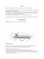
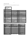
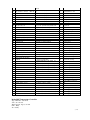
ROASTECH CC
1996/060720/23
Forced Convection Roasting
Mobile 082 770 5711
4C Mill Street, Hamilton, Bloemfontein, 9300
Website : www.roastech.com
info @roastech.com
Fax 086 628 4437
PO Box 31749, Fichardt Park, 9317
Bloemfontein
SOUTH AFRICA
Forced Convection Roaster
Model : R100E
Machine Serial Number : 2013-82
User’s Manual & Technical File
March 2014
This Manual and Technical File entails the documentation and certificates
needed to conform to the European CE marking standards according to the
EC Marking Directives 93/68/EEC and 73/23/EEC
INDEX
Page
1. Preface and Working Principle
1
2. Operating Instructions
4
3. Maintenance
6
4. Safety Precautions
7
5. Quick guide on the Variable Speed Drive
8
6. Roaster Components & Special Procedures
9
7. Electrical Diagram
12
8. Parts list
13
9. Conformity Assessment and Testing
17
10. Declaration of Conformity
18
1.
Preface
Thank you for purchasing our advanced forced convection roasting machines.
It is a proudly South African development and we have filed an application in Geneve for acquiring
worldwide patents (PCT/IB 2008/001008)
The machine is based on high performance heat transfer combined with a simple working principle.
Heat transfer rate to the roasted product is the highest on the market. The product is very evenly
roasted and is not easily matched by other technologies.
The working principle and simplicity make it easy to understand and to operate.
We recommend that you take some time to read this manual, before putting the roaster into service.
Working principle
FCCTR means : Forced Convection Continuous Tumble Roaster
Working Principle
Forced convection roasting is new in the sense that hot air is forced right through the product,
while the product is continuously mixed and moved through the machine.
Electric elements are used to heat the air.
The heated air is continuously re-circulated, resulting in efficient energy usage.
The temperature of the heated air is controlled precisely with an adjustable electronic thermostat.
A perforated rotor with a screw conveyor inside gently conveys the product in the machine while it
is exposed to the hot air treatment.
…/2.
2.
The rotor speed is adjustable to enable the operator to find the exact optimal roasting conditions for
his product.
The operator can easily find the optimal temperature and time settings for the required roasting
result.
When the optimal speed and temperature is set, the roasting conditions are stable, resulting in
continuous precise roasting of each of the particles of the product stream.
The total surface area of each of the particles in process is utilized to transfer heat, resulting in a
very evenly roasted product.
The temperature of the hot air is accurately controlled, so particles will not be exposed to extreme
hot surfaces. (In fact, the maximum temperature inside the machine will not exceed the set-point of
the temperature controller.)
Super heated steam
Moisture from the product replace the hot air inside the machine within 15 minutes from start-up.
This super heated steam (at atmospheric pressure) results in faster and very even heat transfer to
the product.
The machine is thermally insulated, resulting in low heat loss and effective usage of energy for
processing of the product. The typical running cost is less than 20% of conventional gas fired
drum-type roasters at the same capacity.
Incubation
Most of the machines are equipped with an incubation unit where the product is kept at the outlet
temperature to incubate. This is an effective way to cook the products further at the downstream
side of the machine and to develop Maillard browning if necessary.
Management
Electrical interruptions does not cause any serious problems. The machine shuts off when a power
dip occurs. When the power supply has been corrected, the operator puts the machine on; evaluate
the residual temperature; wait for the machine to reach the desired temperature level, and start the
rotor, and production carries on.
The machine does not have to be monitored continuously.
It runs in a “steady state” where all parameters are fixed and every particle receives the same
treatment.
The machine is safe in handling impurities in the product like stones and even dangerous particles
like bolts and nuts.
As soon as the set-point temperature is reached, and the rotor speed is set, the machine can run on
its own.
The product must have a low dust content, for too much small particles will result in smoke and
more frequent cleaning.
…/3.
3.
Proven Technology
We have installed 85 machines in the first four years of production with an combined capacity of
more than 750 000 tons per year.
Our clients range from Dairy Farmers, Veterinarians, Industrial Processors, Business People,
Suppliers to big chain groups, like Central Markets USA, Woolworths and Checkers in SA, and
Universities in Arizona USA, South Africa and Namibia.
We are continually improving the performance of the machines and we do intense research on more
applications and new products.
This precision roasting technology has already replaced micronizing equipment and extruders.
It is successfully used commercially for roasting of soy, corn, coriander, groundnuts (blanch, roast
in the shell and normal roast), macadamia nuts, rolled oats, caramelizing of dehydrated onions
without oil etc. We are doing trials on coffee beans where it seems that taste is drastically
enhanced, due to the new efficient method of heat transfer. (No thermal pinching of the coffee
beans occurs)
No oil is needed for nut roasting and a very even roasted product is produced with many health
benefits.
No particles are burnt, because the operator has full control of the temperature set-point and thus
the maximum temperature inside the machine.
We have initially developed this technology for whole soy beans. Tests have been done at the
University of Free State in Sout Africa, Eskom and private entities on several grains. They are very
excited about the capabilities.
Roasting of Soy is very successful, without losing any proteins and vital fiber. The trypsin
inhibitor has been destroyed to almost 2mg/g. It deactivates urease activity to negligible levels.
…/4.
4.
Operating Instructions
The roaster is designed for continuous use.
The machine is designed for most seeds and nuts bigger than 4.5 mm.
It will not get damaged if it is run without product. The rotor must be running when you put
product into the inlet hopper.
It is better to stop the rotor when all the particles have fallen out of the machine.
PLEASE do not roast material with particle sizes smaller than 4.0 mm, because it will fall through
the rotor apertures and cause smoke – The machine can also catch fire on the inside, especially if it
is not cleaned regularly when roasting products with high fat content, like groundnuts and
macadamia.
The dust tray
The dust tray is installed to catch small particles that would fall through the screen. It can be
cleaned daily if necessary.
Close the dust tray underneath the unit before you start the machine, otherwise the machine will not
work.
Starting procedure
The continuous roaster is adjustable in two ways : Temperature and Time.
If you would like to roast the product at a high temperature for a short time,
you set the temperature at the set-point and the adjust the speed of the
rotor fast to achieve short-time high-temperature roasting.
If you want a low temperature slow roast, you can set the temperature at a the
chosen set-point and adjust the rotor speed slow to achieve your desired result.
Lower rotor speed means that the product stays longer inside the machine, and the
machine will have a lower capacity and vice versa.
The capacity is adjustable between 50 kg/h up to 120 kg/hr, (R100E Model) depending on the
degree of roasting, and the thermal treatment of the seed. We can do 100 kg per hour
on groundnuts and soy beans, but also up to 200 kg/h for blanching of peanuts and up to 300 kg/hr
to pre-heat sunflower seed before cold-pressing. For this application we will have to change the
drive gear ratio.
The incubation unit (if needed) is a thermal insulated box underneath the roaster outlet. This unit
helps to thoroughly after-cook the roasted product. It also make a big difference in colour
development in roasted groundnuts (Maillard browning reaction).
The unit is equipped with a cooling section underneath to cool the product down after incubation.
The processed product is automatically discharged by the delivery auger.
7. Temperature adjustments :
Before starting the machine, make sure all control switches are in the “off” position.
Press the green button and start the Forced Convection Fan. Set the temperature to the
desired value. For most products an ideal starting temperature will be approximately 170°C, but at
higher capacities the temperature must be higher for example : 225 °C at 90% capacity for
soybeans.
Please keep the temperature lower than 250 °C
…/5.
5.
Make sure that the big fan motor is running, because this motor drives the forced convection fan
inside the machine (If the motor does not run, press the red button and get an electrician to attend to
the machine.)
The temperature will start to rise gradually to the set value. The large red indicator light is on,
indicating that the elements are turned on and is adding heat to the air stream inside the machine.
When the set temperature value is reached, the red light will turn off and on, indicating that the
elements turn off an on. The electronic thermostat will turn the elements off and on as heat is
needed to keep the temperature at the set level inside the machine.
2. Rotor speed adjustment
The rotor carry the product through the machine.
The rotor speed is adjustable, so you can roast product fast or slow at a certain temperature.
By playing around with the temperature and speed settings, you can achieve optimal roasting
conditions for your product.
Do not adjust the speed while your sample is inside, because you will not know if the initial setting
was correct.
The variable speed controller can be adjusted between 0 and 90 Hz. This is an indication of the
output frequency to the rotor motor. You must use it to see at what speed your product is roasted
optimally.
(If you take the safety screen off, you will notice that the rotor is turning faster at a higher speed
setting, but be careful that parts of your body do not get caught between the chain and
the sprockets )
Example :
Say you would like to roast groundnuts.
1. Make sure the power supply is on and all switches are in the “off” position
2. Close the dust cover under the processing unit.
3. Press the green button
4. Adjust the temperature to 200 °C
5. Turn the rotor on and set the speed reading to 65 Hz
6. Wait for the temperature to rise to the set-point.- The red light will turn off if the temperature is
reached.
7. Put a hand full of peanuts in the inlet hopper.
8. Start your stopwatch
9. Wait for the peanuts to travel through the machine.
10. The nuts will fall out within ± 8 minutes.
11. Stop your stopwatch when the peanuts start to fall out. – Now you have the time that the
product stays inside the machine at a speed setting of 65Hz and temperature of 200°C
12. Evaluate the product.
13. If it is too dark, it means that the time spent inside the machine was too long. – You must set
the rotor frequency higher for a shorter roasting time.
14. Set the speed to 70 Hz.
…/6.
6.
15. Repeat the procedure from no.7, until you find the optimal speed setting and roasting time at
200°C.
16. Continue to increase or decrease the speed setting to find the optimal roasting time for your
product at 200 °C
17. You can now do the same procedure for 190°C or 220°C.
Remember : Equal sized particles will roast equally.
Do not put in different size particles in one batch, because the small ones will all be darker and the
larger ones lighter. You must have equal sized nuts or seeds if you want to get a proper result.
For a test run, make sure that the temperature set-point is reached and that the rotor is turning at
the required speed.
Put 5 kg in the inlet hopper.
You have to keep the inlet hopper full. The machine will continuously pull the product in.
If the inlet hopper becomes empty, the FC Fan (Forced Convection Fan) will pull cool air into the
processing chamber and disturb the super heated steam, causing un-even roasting of the product
stream.
3. Maintenance
Your electrician can re-tighten all the electrical connectors inside the control box after one week’s
operation. The screws tend to relax with time and variations in temperature, causing a possibility of
hot connections. (It is only necessary to do this once.)
The machine has an external bearing on the rotor drive shaft. This bearing can be greased every
fortnight.
The other end of the rotor is supported in a Teflon Ring inside a taper-lock bush that may need
replacement after about 2000 hours.
Elements may fail from time to time, but we use elements that has a life expectancy of more than
10 years.
The bearings of the Forced Convection Fan may be replaced after 1500 hours, or when necessary.
The speed reducing gearbox is designed for continuous use and an oil replacement may be
necessary after 3000 hours.
The dust trap under the rotor has to be inspected and emptied daily. This must be done more
frequently when small particles is not removed from the product prior to roasting.
It is possible to test the degree of roasting of soybeans with an urease test kit from your supplier.
…./7.
7.
4. Safety Precautions
4.1 Product Specification
It is very important to roast only clean seed.
Seed should not be sticky or wet. It must be free-flowing.
No fine particles are allowed in the product.
This roaster is specifically designed to roast seeds larger than 5mm.
Smaller seeds will fall through the rotor screen and build up inside the dust tray.
If the dust tray is not cleaned out and the small seed, fines or dust builds up in the dust tray, it will
reach a level where the dust tray is filled up with and the Forced Convection Fan will pull the
small particles in.
This will result in the fan blowing the seed over the electrical elements and the seed will land on
top of the seals, between the rotor and housing.
The seed will then build up on top of the seals, and reach the electrical elements, resulting in an
internal fire.
4.2 Internal Fire
In the unlikely case of an internal fire, smoke will emerge from the roaster outlet.
The electronic temperature controller will sense that the temperature inside the machine exceed the
setpoint by more than 20°C.
The alarm in the temperature controller will stop the forced convection Fan.
This will limit the oxygen supply to the internal fire, and the fire will diminish or die.
The rotor will carry on feeding the product through the machine.
When the temperature has dropped to the set point on the Temperature Controller, the alarm
function of the temperature controller will reset, and the forced convection fan will start again.
4.3 Fire Hazard Procedure
4.3.1 DO NOT open the dust tray during an internal fire.
4.3.2 DO NOT use water to try to distinguish the internal fire.
Water will deform the hot surfaces in the roaster, causing permanent damage to the inside of
the machine.
4.3.3 Turn off the inlet elevator to prevent further product supply to the roaster.
4.3.4 Turn off the Forced convection fan, and let the rotor run until the machine is empty.
4.3.5 Leave the machine to cool down – allow at least three hours.
4.3.6 Open the dust tray and inspect the rotor.
4.3.7 Remove the rotor and Forced Convection Fan assembly and clean the machine inside.
…/8.
8.
4.4 Steam, hot surfaces and hot product
Keep all body parts (especially eyes and hands) away form the outlet of the roaster.
Super heated steam escaping with the roasted product can be hazardous.
The dust tray is hot and can be hazardous.
Do not open the dust tray while the machine is running or cooling down.
Do not try to grab roasted products out of the incubation tray while the machine is running.
The product is at a high temperature (~134°C) and can cause burns to the skin.
4.5 Placement of Roaster
Keep the outlet of the roaster away from flammable materials.
5. Quick guide for Yaskava J1000 VSD (Variable Speed Drive)
The Yaskava J1000 VSD can be controlled remotely or locally.
The way that the VSD is wired on your machine is for local control.
Local means : Control is done on the VSD keypad.
If you look at the face of the VSD, you will see a key by the name of Lo/Re.
If you press this key, a small green light will light up next to the Lo side of the key.
This means that the VSD is in “Local control mode”.
Always put it in this mode after you have switched the power on.
If you want to run the motor, make sure that the VSD is in Lo (Local) – mode and press the “start”
button on the VSD.
If you use the remote control setting Re (The tiny light on the Lo/Re button is off), you can change
the output frequency (speed) with the rotatable knob under the VSD unit. The Rotor on/off switch
works together with the remote setting on the VSD
To change the speed :
1. Make sure the display give the reading with an “F” in front, like F050 or F005 etc. This
means that the VSD is showing the current output frequency.
2. Press the ENTER key on the keypad
3. Change the frequency by using the “>” key and the up and down arrows.
4. If you have the right setting, press ENTER again. If the read-out says “End”, then the
reading is accepted. You can then press “ESC” to finish.
5. The maximum frequency for the rotor (The left-hand VSD) was set to 90 Hz, and the
maximum for the feeder VSD (On the right) is 50 Hz.
6. You can also change the speed of the VSD while the motor is running.
7. For further information, refer to the VSD guide inside the control box.
…./9.
13.
6. Roaster Parts List
General Components, Electrical Components and Mechanical Components
Model R100E
Serial Number
2013-82
General Components
No.
Description
Specification
Qty
Application
Frame Components
1
Frame Structural steel
75x75 2.5 Square Tubing
19.60
2
3
Frame Structural steel
Frame Structural steel
32x32x2 Square Tubing
60x60x6 Angle Iron
4.79
3.00
Frame outline
Frame ladder and control box
bracket
Corners front & Back
4
5
6
Frame Structural steel
Frame Structural steel
Rotor Structural steel
60x6 Flat Bar
100x6 Flat Bar
76 mm x 2mm Pipe
1.95
0.40
2.20
Control box bracket
Foot Pieces
Rotor Main shaft
2.00
Outside protection
2.00
0.81
Inside protection
Dust collection under machine
Housing Components
1.6mm 1225x2450 H/R
Plate
2.0mm 1225x2450 H/R
Plate
2.0mm 2240mmx362mm
7
Housing Cover
8
9
10
Internal Housing
Dust Tray
Aerolite Glass Wool
Insulation
75mm x 1.2m x 8m
2.00
Thermal insulation
11
Canopy Clips STD
60mm with latch
5.00
Dust cover and Element Cover
Electrical Components
Roastech R100E
No.
Description
Specification
Qty
Application
1
Steel Enclosure
MCE 315
MCE 111 Orange - 500 H x 400 W x 250 D
1
Control system
2
ABB Box
YOR190
ENLEC BOX 80x80x 55 deep (080806P)
1
3
ABB Box
YOR191
4
Panel Isolator switch 63A
MCE514
ENLEC BOX 120x80x 55 deep (120806P)
2
Temperature Probe housing
In & Outlet Microswitch
housing
UKP-633-PM Panel Mount Isolator 63A
3
Control system
5
Hour meter
MET350
6
Pilot Lights
MCE0395
SQ 48x48 220v
1
Control system
AD22-22DS-GREEN LED PILOT 230V
1
Control system
7
Pilot Lights
MCE0396
AD22-22DS-RED LED PILOT 230V
1
Control system
8
Stop Push Button
MCE050
XB2-BA42 PUSH BUTTON RED
1
Control system - System on
MCE045
9
Start Push Button
XB2-BA31 PUSH BUTTON GREEN
1
Control system
10
Selector Switch 3Position
MCE066
XB2-BD33 3POS SELECTOR SWITCH
2
Inlet Elevator, Outlet auger
11
Selector Switch 2Position
MCE063
XB2-BD21 2POS SELECTOR SWITCH
3
Fan,Rotor,Cooling Fan
12
Blank legend plate complete
For 22mm Switches
10
13
Relay 11-pin
REL017
RELAY 11-PIN 230Vac 601311230 Finder
2
Plate,window, and back piece
Control Circuit Main & Fire
hazrd
14
Base for 11-pin
REL 020
11-PIN RELAY BASES 90.21 Din -Rail
2
Control Circuit
Mount
15
AC Contactor Din Rail
MCE 108
MCE-D3210, 32A per phase , 230 V coil, Din
R
1
Element Bank1-3 : 32A
16
AC Contactor Din Rail
MCE 100
MCE-D0910, 15A per phase , 230 V coil
1
Forced Convection Fan
17
AC Contactor Din Rail
MCE 101
MCE-D0910, 15A per phase , 230 V coil
2
Inlet Elevator
18
AC Contactor Din Rail
MCE 102
MCE-D0910, 15A per phase , 230 V coil
3
Rotor
19
AC Contactor Din Rail
MCE 103
MCE-D0910, 15A per phase , 230 V coil
4
Cooling Fan
20
AC Contactor Din Rail
MCE 104
MCE-D0910, 15A per phase , 230 V coil
5
Outlet Auger
21
AC Contactor Din Rail
MCE 105
MCE-D0910, 15A per phase , 230 V coil
6
Cyclone
22
Circuit Breaker 3P
3 Pole 50A (Din Rail Mount) Merlin Gerin
0
System 50A
23
Circuit Breaker 1P
SQI 004
Single 16 A (Din Rail Mount) Merlin Gerin
1
Control Circuit
24
Thermal Overload
MCE151
MCE2-25 O/L 1 - 1.6 A 0.55 kW for D0910
1
Inlet Elevator / Auger
25
Thermal Overload
MCE151
MCE2-25 O/L 1 - 1.6 A 0.55 kW for D0910
1
Cooling Fan / Cyclone
26
Thermal Overload
MCE151
MCE2-25 O/L 1 - 1.6 A 0.55 kW for D0910
1
Outlet Auger
27
Thermal Overload
MCE154
28
Lugs Crimping (100'5)
LEA019
1
Forced Convection Fan
5mm hole, 2.5sq mm wire
MCE2-25 O/L
2.5 - 4 A 1.5 kW for D0911
0
General use
LEAR Clipin Neutral bar
1
29
LEAR Neutral bar
30
SAM Mini Rail
Mini Rail For LEAR Neutral Bar
1
Control system
31
Slotted Trunking
45 x 45 mm
0
Trunking inside control box
32
Plastic Glands
GLA012
Gland PVC No 0
15
Inlets / Outlets
33
Cable Gland
GLA022
Gland Hellerman No BWR2
1
Main Power Supply
34
Cable Ties (100's)
3mm x 100mm
1
Panel Wiring
35
Lugs Crimping (100'5)
5mm hole, 4.0sq mm wire
0
Panel Wiring
36
Electric Elements
37
Kopex Tubing 25mm
38
Kopex glands 25mm
KOP002
Kopex glands NUTS 25mm
LOC007
39
KOP011
DIN005
3 kW x 1.8m , Posts : Diameter 13mm x M5
0
Heating
2m length
1
Element wire housing
Kopex ends W/T FLEX 25mm
2
Element wire housing
Locknuts Hex Galv 25mm
DIN RAIL SLOTTED P/2m TS35S 2m
length
2
Element wire housing
1
Panel
1.5 sq mm (Needed length in metres)
-
Panel Wiring
40
DIN rail
41
Panel Wire RED 50m
42
Panel Wire Blue 50m
1.5 sq mm (Needed length in metres)
-
Panel Wiring
43
Silicone Wire Red
4.0 sq mm (Needed length in metres)
-
Panel Wiring
44
Silicone Wire Black
4.0 sq mm (Needed length in metres)
-
Panel Wiring
45
Temperature Controller
Bar-tec 0-250°C BTC 404 Type J
-
Temperature Control
46
Temperature probe
Type J - 80mm
2
Temperature Control
47
Invertor controller
Varispeed Yaskawa J1000
-
Rotor speed control
48
Micro Switch
MJ2-1703, 15A 250V AC
2
Inlet Elevator / Auger
49
PVC Cable
16 Sq mm (3 Phase + Earth)
-
50
Cabtire Black (4-core)
1.5 Sq mm (3 Phase + Earth)
4m
Power supply to roaster
Power supp to Forced Conv.
Fan
51
Surfex
1.5 Sq mm (Red,Black + Earth)
-
52
Surfex
1.5 Sq mm (Red,Black + Earth)
-
Power to outlet micro switch
53
Surfex
1.5 Sq mm (3 Phase + Neutral + Earth)
-
Power supply to Cooling Fan
54
Surfex
1.5 Sq mm (3 Phase + Neutral + Earth)
-
Power supply to inlet elevator
55
Surfex
1.5 Sq mm (3 Phase + Neutral + Earth)
-
Power supply to Rotor motor
56
Surfex
1.5 Sq mm (3 Phase + Neutral + Earth)
-
Power supply to outlet Auger
Power to inlet micro switch
Brainchild Temperature Controller
Type : BTC 404 – 41511010
Volts : 90 – 264 Vac
ThermoCouple : Type J, On-Off
O/P 1 : Relay
AL.1 : Relay
…./15.
15.
Veriable Speed Controller
Yaskawa AC Drive : J1000
Supply Voltage : 230 V, 50 Hz, Single phase
Output : 230V ac, Three phase
Capacity : 250 Watt
Frequency setting : 0 to 95 Hz
Motor to be connected in DELTA configuration
Bolts & Nuts
Qty
Allen Cap Bolts Grade 12.9 M10x25
Nylock Nuts : Mild Steel M10
20
35
Consumables
Qty
2
1
5
Paintable silicon
Gasket Sealant Silicon
Laquer thinners
Bearings
Qty
Application
45mm Flange unit - 2 hole FL209
1
Rotor outlet bearing
25mm Flange unit - 4 hole F205
1
Gearbox output bearing
20mm STD Plummer blocks - UCP 204
2
Fan Shaft
08B1 25 Tooth
5
Fan 2x Rotor 2x Gearbox 1x
08B1 57 Tooth
1
Rotor Chain Gear
1610 x 19
1
Extended shaft fan motor
1610 x 20
1
Normal fan motor
1610 x 25
2
1610 x 40
1
2012 x 45
1
Gears
Taper-Locks
Shafts & keys
Qty
Application
Rotor main driveshaft : EN8 - 45mm x 300mm + Cut key 14x4.5x50 - one end
1
Rotor outlet shaft
Rotor intake mainshaft : EN8 - 25mm x 75mm
1
Pivot shaft at intake side
Gearbox outlet shaft : EN8 - 25mm x 225mm + Cut keys - 8x8mm x 25 long both ends
1
Gearbox outlet shaft
Fan main shaft : EN8 - 20mm x 390mm long + Cut keys - 6x6mm x 35 long both ends
1
Fan Shaft
2.5
m
Rotor drive
Chains
08B1 Chain
Gearboxes & Motors - Please assemble
Soya Roasting 120 kg/h
0.18kW 4-pole flange motor 400V ac, 4 pole
1
Rotor drive train
Stage 1 Worm gearbox-NMRV30, Ratio 1:15
1
Rotor drive train
Combination kit - NMRV30 to NMRV50
1
Rotor drive train
Stage 2 Worm Gearbox - NMRV50,25mm shaft, Ratio 1:15
1
Rotor drive train
Outlet flange for NMRV50 - (Fit onto F205 Flange Bearing)
1
Rotor drive train
Please Assemble Auger Gearbox :
0.18kW 4-pole flange motor 400V ac, 4 pole
1
Cooler box
Stage 1 Worm gearbox-NMRV30, Ratio 1:10
1
Cooler box
Gearbox Output Flange
1
Cooler box
1.1 kW 400V,3ph, 2P Fan motor, Standard, Foot Mount
1
Forced Convection Fan
0.18 kW 1 x 2-Pole Standard, Foot mount motor , 400V 3ph
1
Rotor and Cooler box
Motors
…/17.
17.
…./18
18.