1
BCD396XT
The Complete Reference
This document provides a complete reference to all menus, functions, and
features of the BCD396XT Digital Trunk Tracker Scanner from Uniden. It is
based on the Operation Specification that is used both as a guide to the
software engineers for creating the scanner’s user interface and as a
repository for the “final say” on how every feature and function is
implemented.
Some proprietary information has been removed, formatting has been
modified, and extensive editing has been performed to make the text
more readable. However, you will almost certainly find a handful of odd
turns of phrases.
Mostly, though, we hope that this reference work can help you better
understand and use your BCD396XT. This document isn’t intended to be a
guide for how to use your scanner…you’ll find that information in the
Owner’s Manual…but rather a reference for all the things that the scanner
does. Combined with the Owner’s Manual and the great resources
available to scanner users online, you now have more information than
ever on every facet of your scanner.
© 2009 Uniden Corporation
Fort Worth, TX
All Rights Reserved.
Friday, November 07, 2008
1
Contents
Feature Summary .............................................................................................................. 8
Band Coverage ............................................................................................................. 8
Channels ....................................................................................................................... 9
Memory Architecture ..................................................................................................... 9
Channel Memory Scan ................................................................................................. 9
Priority Scan .................................................................................................................. 9
Priority Plus Scan .......................................................................................................... 9
Search with Scan .......................................................................................................... 9
Scan Speed................................................................................................................... 9
Scanning Lockout ......................................................................................................... 10
Temporary Lockout ....................................................................................................... 10
Quick Keys .................................................................................................................... 10
Startup Configuration .................................................................................................... 10
Channel Alert ................................................................................................................ 10
Alpha Tagging ............................................................................................................... 10
Duplicate Input Alert...................................................................................................... 10
Number Tag .................................................................................................................. 10
Trunk Tracking .............................................................................................................. 10
Multi-Site System .......................................................................................................... 11
Control Channel Only.................................................................................................... 11
P25 One-Frequency Trunking ...................................................................................... 11
Priority ID Scanning ...................................................................................................... 11
Preemptive Priority ID Scanning ................................................................................... 11
Trunking Activity Indicators ........................................................................................... 11
Custom Search ............................................................................................................. 11
Quick Search................................................................................................................. 11
Frequency Autostore..................................................................................................... 11
Search Speed / Turbo Search ...................................................................................... 11
Search Lockout ............................................................................................................. 12
Search Key.................................................................................................................... 12
Service Search .............................................................................................................. 12
Broadcast Screen ......................................................................................................... 12
Attenuator...................................................................................................................... 12
Code Search ................................................................................................................. 12
P25 NAC ....................................................................................................................... 12
Volume Offset ............................................................................................................... 12
Friday, November 07, 2008
2
IF Exchange .................................................................................................................. 12
Dropout Delay ............................................................................................................... 13
Weather and SAME Alert .............................................................................................. 13
Close Call® Frequency Capture .................................................................................... 13
Close Call Temporary Store ......................................................................................... 13
Tone-Out Sequential Decode ....................................................................................... 13
Location-Based Scanning* ........................................................................................... 13
Location Alert System*.................................................................................................. 13
Navigation Modes* ........................................................................................................ 13
GPS Compatibility* ....................................................................................................... 13
Wired Cloning................................................................................................................ 13
Band Scope................................................................................................................... 13
PC Control..................................................................................................................... 14
LCD and Keypad Backlight ........................................................................................... 14
Alert Tone Level ............................................................................................................ 14
Battery Low Alert........................................................................................................... 14
Battery Save.................................................................................................................. 14
Key Lock ....................................................................................................................... 14
Key Safe Mode.............................................................................................................. 14
Audio AGC .................................................................................................................... 14
Repeater Reverse ......................................................................................................... 14
Memory Backup ............................................................................................................ 14
Design ................................................................................................................................ 15
Controls and Keys.............................................................................................................. 16
Displays.............................................................................................................................. 21
LCD Design ................................................................................................................... 21
Icons .............................................................................................................................. 21
Dot Matrix ...................................................................................................................... 22
LCD Flashing Time ....................................................................................................... 22
Tones ................................................................................................................................. 23
General Tones .............................................................................................................. 23
Weather Alert Sirens ..................................................................................................... 23
Tones in Menu Mode .................................................................................................... 24
Selecting a menu item ............................................................................................. 24
Editing a name or a frequency etc ........................................................................... 24
Alert in Scanner Mode .................................................................................................. 24
Alert in GPS Mode ........................................................................................................ 24
Friday, November 07, 2008
3
Alert for Point Of Interest ......................................................................................... 24
Alert for Dangerous Xing.......................................................................................... 24
Alert for Dangerous Road ........................................................................................ 24
Battery Low Tone .......................................................................................................... 24
Operation ........................................................................................................................... 25
Power On ...................................................................................................................... 25
Volume and Squelch Control ........................................................................................ 26
Volume Adjust Mode ................................................................................................ 26
Squelch Adjust Mode ............................................................................................... 26
P25 Condition Mode ................................................................................................ 27
State Transition Diagram ......................................................................................... 27
Menu Mode ................................................................................................................... 28
General Operations .................................................................................................. 28
Error Messages ........................................................................................................ 31
Top Menu ................................................................................................................. 32
Program System ...................................................................................................... 32
Program Site ............................................................................................................ 45
Program Group ........................................................................................................ 55
Program Channel ..................................................................................................... 59
Program Location ..................................................................................................... 67
Srch/CloCall Opt ...................................................................................................... 72
Search for... .............................................................................................................. 78
Close Call ................................................................................................................. 89
Priority Scan ............................................................................................................. 94
WX Operation........................................................................................................... 95
Tone-Out for … ........................................................................................................ 98
Wired Clone ............................................................................................................. 102
Settings .................................................................................................................... 103
SCAN MODE ................................................................................................................ 111
Display during Scan Mode ....................................................................................... 111
Startup Key Operation ............................................................................................. 111
Start Scanning.......................................................................................................... 111
Scanning Order ........................................................................................................ 113
Scanning Operation ................................................................................................. 114
Temporary System Hold .......................................................................................... 126
System Hold ............................................................................................................. 127
Quick System Select ................................................................................................ 127
Friday, November 07, 2008
4
Quick Save for CTCSS/DCS/P25 NAC Data ........................................................... 128
Key Operation During Scan ..................................................................................... 129
SCAN HOLD MODE ..................................................................................................... 131
Display while in Scan Hold Mode ............................................................................ 131
General Operation.................................................................................................... 131
Hold on Conventional System ................................................................................. 135
Hold on Trunked System ......................................................................................... 135
Hold on TalkGroup ID from ID Search / ID Scan ..................................................... 136
Direct Entry .............................................................................................................. 136
Key Operation During Scan Hold Mode .................................................................. 139
PRIORITY SCAN .......................................................................................................... 142
Priority Scan ............................................................................................................. 142
Priority Plus Scan ..................................................................................................... 143
Key Operation During Priority Scan ......................................................................... 143
PRIORITY ID SCAN ..................................................................................................... 144
Priority ID Scan ........................................................................................................ 144
Key Operation During Priority ID Scan .................................................................... 144
SEARCH MODE ........................................................................................................... 145
Display during Search Mode .................................................................................... 145
General Operation.................................................................................................... 145
Service Search ......................................................................................................... 146
Custom Search ........................................................................................................ 147
Custom Search in Control Channel Only Mode....................................................... 148
Search and Store ..................................................................................................... 149
Quick Search............................................................................................................ 149
Key Operation During Search Mode ........................................................................ 151
SEARCH HOLD MODE ................................................................................................ 153
General Operation.................................................................................................... 153
Go to Quick Search Hold Directly ............................................................................ 153
Direct Entry .............................................................................................................. 153
Quick Save ............................................................................................................... 154
Key Operation During Search Hold Mode ............................................................... 155
CLOSE CALL MODE .................................................................................................... 157
Display during Close Call Mode ............................................................................... 157
Close Call Search .................................................................................................... 157
Close Call Only ........................................................................................................ 160
Close Call Hold ........................................................................................................ 161
Friday, November 07, 2008
5
Close Call Auto Store ............................................................................................... 161
CC Hit with Scan ...................................................................................................... 162
Direct Entry / Quick Save / Go to Quick Search Hold Mode ................................... 162
Key Operation During Close Call Only Mode .......................................................... 163
Key Operation During Close Call Hold Mode .......................................................... 164
WEATHER SCAN MODE ............................................................................................. 167
Normal Weather Scan .............................................................................................. 167
Weather Alert Scan .................................................................................................. 167
Weather (Alert) Scan Hold ....................................................................................... 168
Weather Alert Priority (WX Alt Priority) .................................................................... 169
Direct Entry / Quick Save ......................................................................................... 169
Key Operation During Weather (Alert) Scan Mode ................................................. 169
Key Operation During Weather (Alert) Scan Hold Mode ......................................... 170
TONE-OUT MODE ....................................................................................................... 172
Display during Tone-Out Mode ................................................................................ 172
Tone-Out Standby Mode.......................................................................................... 173
Tone-Out Search Mode ........................................................................................... 175
Tone-Out Hold Mode ............................................................................................... 176
Key Operation During Tone-Out Mode .................................................................... 177
GPS MODE ................................................................................................................... 179
Display Mode in GPS Mode ..................................................................................... 179
Location Alert Operation .......................................................................................... 181
Registration of Location Information ........................................................................ 184
Review Location Mode............................................................................................. 185
Key Operation During GPS Mode............................................................................ 187
BAND SCOPE MODE................................................................................................... 189
Scope Mode ............................................................................................................. 189
Search Mode ............................................................................................................ 190
Max Hold Search Mode ........................................................................................... 190
Hold Mode ................................................................................................................ 191
General Operation.................................................................................................... 191
Search Setting Parameters ...................................................................................... 193
Key Operation during Band Scope Mode ................................................................ 194
WIRED CLONE MODE ................................................................................................. 196
Confirm State ........................................................................................................... 196
Transferring State .................................................................................................... 196
Complete State ........................................................................................................ 196
Friday, November 07, 2008
6
Error State ................................................................................................................ 197
Key Operation During Clone Mode .......................................................................... 197
KEYLOCK ..................................................................................................................... 198
KEY SAFE MODE ......................................................................................................... 199
Changed Key Operation in Key Safe Mode............................................................. 199
Key Safe Operation .................................................................................................. 200
Key Safe Message ................................................................................................... 200
MEMORY INITIALIZATION .......................................................................................... 201
BATTERY CHARGE ..................................................................................................... 202
Battery Type Select .................................................................................................. 202
Charging the Battery ................................................................................................ 202
OTHERS ............................................................................................................................ 205
AVAILABLE SYSTEM SETTINGS................................................................................ 205
System Settings ....................................................................................................... 205
System Option Settings ........................................................................................... 205
Site Settings ............................................................................................................. 206
Site Frequency Settings ........................................................................................... 206
Channel Settings ...................................................................................................... 207
TGID FORMAT FOR TRUNKED SYSTEM .................................................................. 208
FLEET MAP .................................................................................................................. 215
PRESET FLEET MAPS ................................................................................................ 216
WEATHER CHANNELS ............................................................................................... 217
CTCSS FREQUENCY .................................................................................................. 217
DCS CODE ................................................................................................................... 217
CEA2009-SAME EVENT CODE(ANSI/CEA-2009-A October 2005) ........................... 218
REMOTE COMMAND................................................................................................... 220
CTCSS/DCS CODE LIST ............................................................................................. 264
Friday, November 07, 2008
7
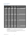
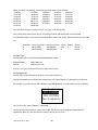
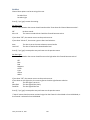
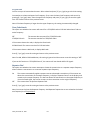
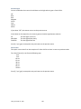
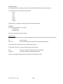
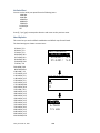
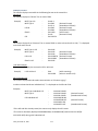
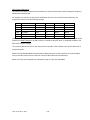
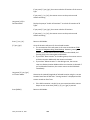
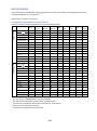
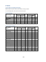
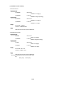
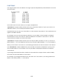
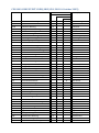
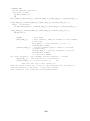
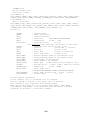
Feature Summary
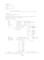
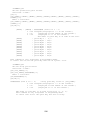
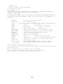
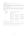
Band Coverage
Frequency (MHz)
Modulation Step (kHz) Remark
Lower Edge
Upper Edge
25.0000
26.9600
AM
5.0
Petroleum Products & Broadcast Pickup
26.9650
27.4050
AM
5.0
CB Class D Channel
27.4100
27.9950
AM
5.0
Business & Forest Products
28.0000
29.6800
NFM
20.0
10 Meter Amateur Band
29.7000
49.9900
NFM
10.0
VHF Low Band
50.0000
53.9800
NFM
20.0
6 Meter Amateur Band
54.0000
71.9500
WFM
50.0
VHF TV Broadcast 2 – 4
72.0000
75.9950
FM
5.0
Intersystem & Astronomy
76.0000
87.9500
WFM
50.0
VHF TV Broadcast 5 – 6
88.0000
107.9000
FMB
100.0
FM Broadcast
108.0000
136.9916
AM
8.33
Aircraft Band
137.0000
143.9875
NFM
12.5
Military Land Mobile
144.0000
147.9950
NFM
5.0
2 Meter Amateur Band
148.0000
150.7875
NFM
12.5
Military Land Mobile
150.8000
161.9950
NFM
5.0
VHF High Band
162.0000
173.9875
NFM
12.5
Federal Government
174.0000
215.9500
WFM
50.0
TV Broadcast 7 – 13
216.0000
224.9800
NFM
20.0
1.25 Meter Amateur Band
225.0000
379.9750
AM
25.0
UHF Aircraft Band
380.0000
399.9875
NFM
12.5
Military Band
400.0000
405.9875
NFM
12.5
Miscellaneous
406.0000
419.9875
NFM
12.5
Federal Government Land Mobile
420.0000
449.9875
NFM
12.5
70 cm Amateur Band
450.0000
469.9875
NFM
12.5
UHF Standard Band
470.0000
512.0000
NFM
12.5
UHF TV
763.0000
775.9937
NFM
6.25
Public Service Band
793.0000
805.9937
NFM
6.25
Public Service Band
806.0000
823.9875
NFM
12.5
Public Service Band
849.0125
868.9875
NFM
12.5
Public Service Band
894.0125
960.0000
NFM
12.5
Public Service Band
1240.0000
1300.0000
NFM
25.0
25 cm Amateur Band
Notes on Band Coverage:
You can edit the Modulation and Step for each band. The above table shows the factory
default values.
Although TV bands are listed, the BCD396XT cannot decode Digital TV audio.
When you select “AUTO” for a channel or mode’s Modulation or Step, the above value is
used (unless you’ve edited the Band Defaults).
Friday, November 07, 2008
8
Channels
Dynamic – You can create up to 25,000 total conventional channels, trunked channels, and trunked system
frequencies.
Channels in a conventional system contain a frequency.
Channels in a trunked system contain a talk group ID (TGID).
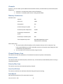
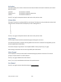
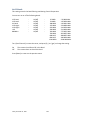
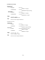
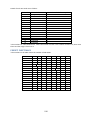
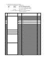
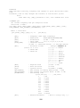
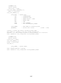
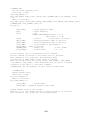
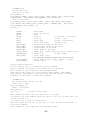
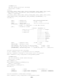
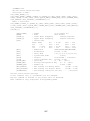
Memory Architecture
Absolute Limits:
Systems
500
Sites Total
1,000
Sites/System
256
Channel Groups per System
20
Channels+System Frequencies
25,000
Channels per conventional
system
1000
Channels per trunked system
500
Trunk Frequencies per Site
500-1000 (depending on total
TGIDs stored in the system)
Notes about limits:
The actual results will be limited by the first absolute limit you hit. For example, if you
have created 1000 sites, you will not be able to create a new system even though you have
created fewer than 500 systems.
You can check the % of memory used by using the menu.
Channel Memory Scan
The scanner can scan any combination of trunked and conventional systems simultaneously.
Priority Scan
The scanner checks conventional priority channels every 1-10 seconds (2 seconds default) when scanning a
conventional system.
Priority Plus Scan
The scanner scans only the conventional priority channels.
Search with Scan
The scanner can do Service and Custom Searches along with system scanning.
Scan Speed
100 Channels/Second (max) for conventional systems.
Friday, November 07, 2008
9
Scanning Lockout
You can lock out any System, Site, Channel Group, Channel, or search frequency.
Locked out channels are skipped (or ignored) during scanning.
If a system, site, or channel group is locked, all channels belonging to it will be skipped during scanning.
Temporary Lockout
Sites, Systems, Channels, or Frequencies temporarily locked out are automatically unlocked when power is
cycled.
Quick Keys
You can assign an SQK (System/Site/Search Quick Key) from 0-99.
You can assign a GQK (channel Group Quick Key) from 0-9.
Quick keys can be rapidly enabled/disabled from the keypad during scanning.
Startup Configuration
You can assign a startup configuration key to a system or search range so that it can be automatically
locked out or unlocked during power up.
Channel Alert
You can set a separate audible/visual alert for each channel.
Alpha Tagging
You can assign an alphanumeric name to each System, Site, Channel Group, Channel, Location, Custom
search range, SAME group, and Tone-Out. You can use 16 characters per tag.
Duplicate Input Alert
The scanner will alert you if an entered alpha tag, frequency, etc has already been used in the same
system.
Number Tag
You can assign a unique number tag from 0-999 to each system and to each channel within a system. This
tag allows you to rapidly tune to a specific channel.
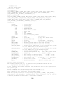
Trunk Tracking
The scanner can track the following types of trunked systems:
Motorola Type I 800
Motorola Type II 800, 900, UHF, VHF
Motorola Rebanded
EDACS Wide, Narrow, SCAT
EDACS ESK (No ProVoice Decoding)
LTR
APCO P25 Standard, P25 One-Frequency
Friday, November 07, 2008
10
Multi-Site System
All trunked systems can have more than one site. All sites in the system share the same Channel Groups
and Channels.
Control Channel Only
Trunk Tracking can be achieved by entering only the control channels for Motorola and P25 systems.
P25 One-Frequency Trunking
The scanner can follow individual talk groups on P25 single-frequency systems that use both NAC and
TGID’s for squelch control and user identification. ID Search and ID Store are available, just like on trunked
systems.
Priority ID Scanning
Trunked channels can be assigned priority. When the scanner is monitoring the control channel, channels
you tag as priority are given a higher priority over non-priority channels when they become active.
Preemptive Priority ID Scanning
For Motorola systems that have channel priority active on the system, if you flag a channel as priority and
the system also has that TGID identified as a priority channel, the scanner will preempt any current
transmission if the TGID becomes active.
Trunking Activity Indicators
The scanner shows all trunked activity when you hold on the control channel.
Custom Search
You can program up to 10 custom search ranges and either search them exclusively or include these
searches when scanning.
Quick Search
If you hold on a conventional channel, you can start searching from the current frequency. If you hold on a
trunked channel, you can quickly switch to ID Search mode.
Frequency Autostore
The scanner can automatically store frequencies found during a search.
Search Speed / Turbo Search
100 Steps/Second in search mode (max, except for 5 kHz steps)
300 Steps/Second in search mode (max, 5 kHz steps)
Turbo mode automatically applies to 5 kHz step searches.
Friday, November 07, 2008
11
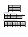
Search Lockout
You can lock out up to 500 frequencies.
The limit of temporary L/O frequencies: 250
The limit of permanent L/O frequencies: 250
Locked out frequencies will be skipped in Search Mode or Close Call Mode.
You can review all locked out frequencies in Menu Mode.
Search Key
Search keys are short cuts to start searching for a single search range.
There are 3 search keys (sr1 to sr3).
Service Search
You can search preset frequencies typically used by specific agencies or groups.
The kind of Service Search is as follows: Public Safety, News, HAM Radio, Marine, Railroad, Air, CB Radio,
FRS/GMRS/MURS, Racing, FM Broadcast, Military Air, Special
Broadcast Screen
Allows the scanner to ignore hits on Pager, FM, UHF TV, VHF TV, NOAA WX and custom band frequencies.
Attenuator
You can attenuate the incoming signal for channels that get interference from strong signal sources.
You can set a global attenuator to apply attenuation to all reception.
Code Search
Rapid search for the CTCSS/DCS used during a transmission.
The scanner does not detect or decode P25 signals if you are operating CTCSS/DCS Search.
P25 NAC
P25 Network Access Code (NAC) is used to provide selective squelch operation on channels. The scanner
can also search for the NAC code that is being used on a P25 digital channel.
Volume Offset
Adjust the volume level for any channel from -3 to +3 steps to balance audio level.
IF Exchange
Switches the current frequency to use a different IF (intermediate frequency) for receiving radio signals to
avoid interference.
Friday, November 07, 2008
12
Dropout Delay
Controls whether the scanner pauses at the end of a transmission to wait for a reply.
You can set the Delay time for each System. All Channels in the System share the same delay setting. You
can also set the Delay time for Search, Close Call and Tone-Out.
You can set the minus delay time. In that case, the scanner only stops on transmissions for the set
duration, then automatically resumes.
Weather and SAME Alert
The scanner can alert to Weather Alert Tone, all FIPS or selected FIPS.
Close Call® Frequency Capture
The scanner can immediately detect and lock onto a transmission above threshold signal strength.
Close Call Temporary Store
The scanner scans the last 10 frequencies captured by Close Call so that you can continue to receive the
signal even after the signal is not strong enough to trigger a Close Call hit..
Tone-Out Sequential Decode
Lets you set the scanner to act as a two-tone pager for fire tone-out standby. If you do not know the tones
being used, the scanner can detect the tones when it receives a page.
Location-Based Scanning*
The scanner can automatically lock and unlock systems, sites and channel groups based on your current
location as provided by an external GPS unit (not included).
Location Alert System*
The scanner alerts you when you approached a stored location.
Navigation Modes*
Indicate the Direction / Distance / Time to Goal for locations you set.
GPS Compatibility*
Compatible GPS units output location data that conforms to NMEA-0183 v3.01. The scanner uses the GGA
and RMC sentences as defined by that specification. Note that this standard specifies an RS232 serial
connection. GPS units that have USB connectivity are not compatible with this scanner.
Wired Cloning
You can clone all programmed data, including Memory Architecture, Menu settings and other parameters
from one BCD396XT to another BCD396XT connected with RS232C cable.
Band Scope
Band Scope Mode searches a frequency range and displays a graphic of the signal level in real time.
In Band Scope Hold Mode, the user can monitor the frequency displayed.
Friday, November 07, 2008
13
PC Control
You can download information into the scanner and control the scanner via your personal computer.
LCD and Keypad Backlight
You can select your desired LCD backlight color from White, Red, Magenta, Blue, Green, Cyan, or Yellow.
The Keypad backlight is single white.
The backlight can be adjusted to 3 different brightness levels
Alert Tone Level
This feature lets you adjust the volume level of the following tones: Key Beep, Emergency Alert, Channel
Alert, Close Call Alert, Tone-Out detection Alert, Battery Low Alert and Location Alert.
Battery Low Alert
When the battery voltage becomes low, the
icon will blink and a Battery Low Tone will be generated
every 15 seconds. This alert level is set at the same level as the key beep volume level.
Battery Save
You can turn on/off this function by Menu Operation.
This works when there is no transmission over 1 minute in the following modes. This feature turns off RF
power for 1 second and turns on it 300 ms to extend the battery life.
Scan Hold Mode at a Channel of conventional System (without Priority Scan)
Any Search Hold Mode
Key Lock
This feature disables the keypad and scroll to prevent any accidental input.
Key Safe Mode
This mode helps keep novice users from accidentally changing parameters or modes.
Some keys don't work in this mode.
Audio AGC
The scanner judges strength of the signal and changes the volume automatically.
Repeater Reverse
One-touch key lets you switch to hearing the input frequency on a conventional repeater system or
trunked system.
Memory Backup
Scanner memory is backed up semi permanently.
Friday, November 07, 2008
14
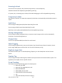
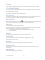
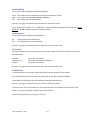
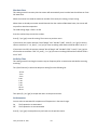
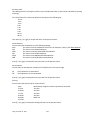
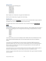
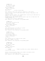
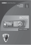
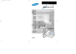
Design
The below is a design reference. There might be some differences between this image and the actual final
design.
Friday, November 07, 2008
15
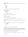
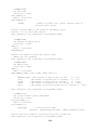
Controls and Keys
“Long press” means pressing a key more than 2 second.
Each key has a “normal” mode and a “Function” mode.
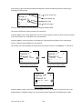
Normal Mode:
Normal Mode means that the scanner is not in Function Mode. In this mode, the F icon is not displayed.
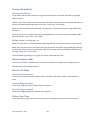
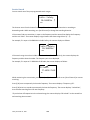
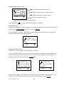
Function Mode:
Pressing [FUNC] puts the scanner into Function Mode for 3 seconds. While it is in Function Mode,
the scanner displays the F icon. If you press a button, the Function Mode time is continued for
another 3 seconds.
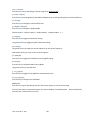
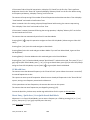
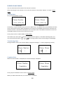
Long pressing [FUNC] puts the scanner into Function Mode without a timeout. The scanner
displays “Function Key” and “Holding”, and the F icon blinks.
F
Functi on Key
Holdi ng
S0: - - - - - - - - - GRP- - - - - - - - -
Pressing [FUNC] again in each Function Mode returns to Normal Mode and the F icon disappears.
Scroll Control
Selects a channel or frequency in Hold Mode.
Selects Menu items in Menu Mode.
Selects a character while editing the Name.
Sets the level in Volume / Squelch Level Control mode.
Scroll Control Push
Pressing this works the same operation as pressing [E / yes / gps] in Menu Mode.
Press this to set the volume level in the mode that is not Menu Mode.
Function + Scroll Control
Use to select a System in Scan or Scan Hold Mode.
Function + Scroll Control Push
Press this to set the squelch level in any mode other than Menu Mode.
Scan / srch (Search) Key
Press to resume scanning. (Scan Hold Mode and while monitoring a channel in Scan Mode)
Press to go to Scan Mode. (Except Scan Mode, Scan Hold Mode and GPS Mode)
Press to return to the scanner screen. (GPS Mode)
Friday, November 07, 2008
16
Function + Scan / srch Key
Press to resume searching. (Search Hold Mode and while monitoring in Search Mode)
Press to toggle between ID SCAN and ID SEARCH while scanning a trunked system.
Press to display the Quick Search Prompt. (Except in Search Mode, Search Hold Mode, GPS Mode
and Band Scope Mode)
Press to return to the scanner screen. (GPS Mode)
Press to change the band scope search type. ( Band Scope Mode)
Hold /
(Close Call) Key
Press to go to each Hold Mode. (Scan Mode, Search Mode, Close Call Only Mode, WX Scan Mode
and Band Scope Mode)
In Close Call Only Mode, the scanner sounds an Error Tone if it has not yet gotten a hit.
Press to resume scanning or searching. (Hold Mode)
Function + Hold /
Key
Toggles the setting of Close Call.
Long press to start Close Call Only Mode.
L/O (Lockout) Key
Press once to temporarily lock out a system channel, a search frequency or a location data. This
lock out is canceled when the power is turned off then back on.
Press twice within one second to permanently lock out a system channel, a search frequency or a
location data. This lockout remains even if the power is turned off.
Long press to unlock all settings of the current system. (Scan Mode and Scan Hold Mode)
All Locations of the current Type are unlocked by long-pressing this key. (Review Location Mode)
The scanner unlocks all frequencies of Global Lockout List*. (Search Mode, Search Hold Mode,
Close Call Only Mode and Close Call Hold Mode)
Press to cancel a prompt without changing settings in Menu Mode.
*Global Lockout List means collecting the locked out frequencies at Search Mode, Search Hold Mode,
Close Call Only Mode and Close Call Hold Mode.
Friday, November 07, 2008
17
Function + L/O Key
Press once to temporarily lock out the current system, current site or current search range in Scan
Mode and Scan Hold Mode. This lock out is cleared when power is turned off then back on.
Press twice in a second to permanently lock out the current system or current search range in Scan
Mode and Scan Hold Mode. This locked out is kept even if the power is turned off.
Press to go to Rvw Search L/O. (Search Mode, Search Hold Mode, Close Call Only Mode and Close
Call Hold Mode)
Long press to display the prompt to unlock all systems, sites, search ranges and Close Call Hits
system and enable all Quick Keys for systems/sites/search ranges. (Scan Mode and Scan Hold
Mode) If you press [E / yes / gps], the scanner unlocks all data. If you press [. / no / pri], the
scanner returns to the previous mode without unlocking.
Long press to display the prompt for unlocking all Locations of all types. (Review Location Mode of
GPS Mode) If you press [E / yes / gps], the scanner unlocks all data. If you press [. / no / pri], the
scanner returns to the previous mode without unlocking.
(Light) /
(Power) /
(Key Lock)
Press to illuminate the LCD back light according to Menu setting.
Press and hold to turn the scanner on or off.
Function + /
/
Key
Press to lock or unlock the keypad.
1 - 9, 0 Key
Press to enable or disable the System/Site/Search Quick Key for system or search range. (Scan
Mode)
Press to turn on or off each custom search range number. These keys operate only in Custom
Search and not in other searches. (Search Mode)
Press to go to Direct Entry Mode or to enter a Number Tag. (All Hold Mode, Close Call Mode and
Tone-Out Mode)
While editing a name, press [4 / LEFT] or [6 / RIGHT] to move the cursor to the left or right.
Function + 1 - 9, 0 Key
Press to enable or disable Groups Quick Key in Scan Mode.
Function + 1 - 3 / sr1 - 3 (Search) Key
Press [1 – 3 / sr1 - 3] to start Service Search, Custom Search, Tone-Out Mode or Band Scope Mode
in Set Search Key. (except Scan Mode and GPS Mode)
Function + 4 / LEFT / ifx (IF Exchange) Key
Press to exchange the IF (intermediate frequency) for receiving radio signals to avoid interference.
(except Scan Mode and GPS Mode)
Function + 5 / lvl (Volume Offset) Key
Press to change the volume offset level. (Scan Hold Mode)
Friday, November 07, 2008
18
Function + 6 / RIGHT / disp Key
Press to change the Display Mode. (Scan Hold Mode and Custom Search Mode)
(Display mode 1 -> Display mode 2 -> Display mode 3 -> Display mode 1 ->….)
Press to change the GPS Display. (GPS Mode)
Function + 7 / att (Attenuator) Key
Press to toggle the attenuation state. (except GPS Mode)
Long press to toggle global attenuator. (except GPS Mode)
Function + 8 / rev (Reverse) Key
Press to monitor the current frequency’s reverse frequency. It returns to current frequency when
the key is released. (Scan Hold Mode, Search Mode, Search Hold Mode, Close Call Only Mode and
Close Call Hold Mode)
Function + 9 / mod (Modulation) Key
Press to change the modulation state. (except GPS Mode and WX Scan Mode)
Function + 0 / wx (Weather) Key
Press to toggle WX Scan Mode and WX Alert Scan Mode while WX Scan or WX Alert Scan.
Press to toggle WX Alert Priority. (except WX Scan Mode)
Long press to start WX Scan. (except WX Scan Mode)
. (Decimal) / no / pri (Priority) Key
Press to cancel these displays while displaying Error or Warning message.
Press to input "."(decimal) for frequency.
Press to input "-" or "i" for TGID.
Press to input a space in editing a data name.
Press twice to clear the data in editing data name.
Press to input “-“ or “i” for Direct Enter in Hold Mode, Close Call Only Mode, Tone-Out Mode.
Press in Scan Mode to start the selection for the ten's place of a System/Site/Search Quick Key.
Then, press number key to jump to each number's place of a Quick Key.
Function + . / no / pri Key
Press to toggle Priority Mode in Scan Mode. (On / Plus On / Off)
E (Enter) / yes / gps Key
Press to accept the input data or a Menu Item.
Press to edit the channel data. (Scan Mode and Scan Hold Mode)
Press to quickly save the frequency in Search Mode, Search Hold Mode, Close Call Mode, Close Call
Hold Mode, WX Scan Mode and WX Scan Hold Mode.
Press to go to the editing menu for current Tone-Out.
Press to go to Review Location Mode. (GPS Mode)
Function + E / yes / gps Key
Press to change GPS Mode.
Long press to store a current location data.
Friday, November 07, 2008
19
Menu Key
Press to enter the Menu Mode.
Press to go back up one menu level when in the Menu Mode.
Press after entering the value to indicate going to a number tagged system or channel.
Function + Menu Key
Press to go to the editing menu for the current system, search range or location data.
Friday, November 07, 2008
20
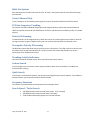
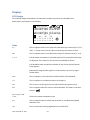
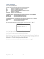
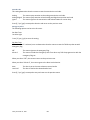
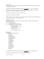
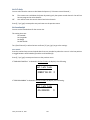
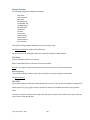
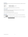
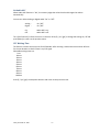
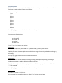
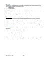
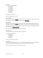
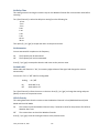
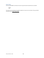
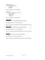
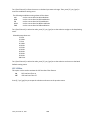
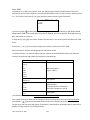
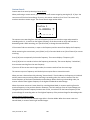
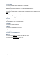
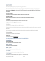
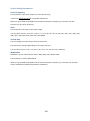
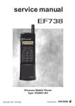
Displays
LCD Design
The reference design shown below is for illustration purposes only and is not intended to be a
photorealistic representation of the display.
F HOLD L/O PRI
ABCDEFGHI JKLMNOP
abcdefghi jklmnop
P
WFM
ATT P25
S0: 1 2 3 4 5 6 7 8 9 0
GRP 1 2 3 4 5 6 7 8 9 0
WX
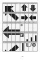
Icons
Sx: :
This icon appears with icons of System and Site Quick Key numbers (from “0” to
“99”). “x” shows the current ten’s place of Quick Keys for Systems or Sites.
GRP:
This icon appears with icons of Quick Key number for Channel Groups (1 - 9, 0).
1 - 9, 0:
In SCAN mode, the numbers of unlocked Quick Key for Systems/Channel Group
are displayed. The number for the currently scanned SQK set flashes.
In SCAN HOLD mode, the Quick Key number for the current System/Channel
Group appears.
Enabled User Range numbers appear in Custom Search; the current range’s
number blinks.
HOLD:
This icon appears in Scan Hold, Search Hold and Close Call Hold Mode.
L/O:
This icon appears at a locked out Channel or frequency.
PRI :
This icon turns on during Priority Scan and this blinks during Priority Plus.
GPS:
This icon appears when the scanner receives GPS data. This shows in the same
place as "
".
AM / FM / NFM / FMB
/ WFM:
These icons show the modulation type.
ATT:
This icon appears when a channel has attenuator on and blinks when global
attenuator is on.
P25:
This icon shows the receiving digitalized voice of APCO P25.
Friday, November 07, 2008
21
LNK:
This icon appears when data is received on a VOICE CHANNEL. This shows in the
same place as "P25".
DAT:
This icon appears when data on CONTROL CHANNEL is received. This shows in
the same place as "P25" icon.
ENC:
This icon appears when encrypted APCO P25 digitized voice is received. The
scanner mutes audio. This shows in the same place as "P25".
C67. 0 / DCS023 /
NAC:000 / etc.:
The scanner displays the CTCSS/DCS/P25 NAC here. This shows in the same
place as "P25".
SCR:
This icon appears when one or more Broadcast Screen Band is set to on.
WX:
This icon turns on while the Weather Alert Priority Scan works.
F (Function icon) :
This icon appears in Function Mode. Function Mode does not have a timeout
when this icon blinks.
P (Priority Channel) :
This icon appears when the channel set to “Priority On".
(Signal Indicator) :
This icon shows strength of the signal from 0 to 5.
(KEYPAD LOCK):
This icon will appear only when the KEYLOCK function is On.
(BATTERY Low Alert): This icon blinks when the battery voltage is low. This icon blinks when a bad
battery is installed and an AC adapter is connected. This icon appears during
battery check.
(Close Call Pri ) :
This icon appears in Close Call Priority Mode. This blinks in Close Call Only Mode
or when the scanner gets a Close Call hit.
(Close Call DND) :
This icon appears in Close Call DND Mode is CC DND Mode. This is a reverse
display of Close Call Pri icon.
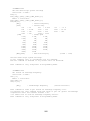
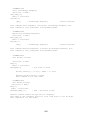
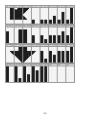
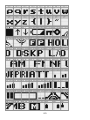
Dot Matrix
The display element consists of a 128 x 64 pixel display. See Font Data for character patterns.
Since the display is entirely dot matrix, a great variety of different things can be shown. The above shows
the most common display elements in most modes. Additional examples are shown throughout this
reference guide.
LCD Flashing Time
About 500 mS on/500 mS off (1 Hz).
Friday, November 07, 2008
22
Tones
The scanner can produce 3 fundamental tones, high (1200 Hz), middle (920 Hz), and low (640 Hz).
Furthermore, there are Alert Tones and Weather Alert Sirens which include other sounds.
Additionally, special alert tones (Location Alert, CC alert, Emergency alert and WX alert, etc) can be set to
custom volume levels.
General Tones
Key Touch Tone
When you press valid keys, the scanner will sound single high beep for 50 mS.
Confirmation Tone
The scanner will sound double high beep for confirmation (50 ms beep - 100 ms silent - 50 ms beep).
Exec Tone
When you press [E / yes / gps] key etc. to accept the entry or setting, the scanner will sound high-middle
beep (75 ms high beep - 25 ms silent - 75 ms middle beep).
Error Tone
When you press a key that does not have a valid function in the current mode, the scanner will sound a
triple low beep (75 ms beep - 25 ms silent -- repeat 2 times)
Weather Alert Sirens
The scanner sounds the following tones until any key is pressed, or for 8 seconds.
For Warning
[100 ms 120 Hz - (20 ms every 150 - 195 Hz in 5 Hz step) - (30 ms every 200 - 590 Hz in 10 Hz step) - 500 ms
600 Hz - 100 ms silent] --- repeat
For Watch
[(50 ms 800 Hz - 30 ms silent - 50 ms 1050 Hz - 30 ms silent) -- repeat 3 times - 170 ms silent] --- repeat
For Advisory
[100 ms 800 Hz - 50 ms silent - 100 ms 1050 Hz - 500 ms silent] -– repeat
For Weather Alert Tone: Same as Weather Alert Siren For Warning.
Friday, November 07, 2008
23
Tones in Menu Mode
Selecting a menu item
As you step to the next menu item by turning [Scroll Control] knob, the scanner will sound a single high
beep for 100 ms.
However, if the menu item is the last item and you turn [Scroll Control] knob in the clockwise direction, the
scanner will sound a double high beep (75 ms beep - 25 ms silent - 75 ms beep).
When you select a menu item by pressing [E / yes / gps] key, the scanner will sound a single middle beep
for 100 ms.
Or, when you return to a previous menu by pressing [MENU] key, the scanner will sound a double middle
beep (75 ms beep - 25 ms silent - 75 ms beep).
Editing a name or a frequency etc
When you select letters, the scanner sounds a single high beep for every click of the [Scroll Control] knob.
When you move the cursor from the left to the right, the scanner will sound a single middle beep (100 ms).
Or, when you move the cursor from the right to the left, the scanner will sound a double middle beep (75
ms beep - 25 ms silent - 75 ms beep).
If you store data by pressing [E / yes / gps], the scanner sounds the Exec Tone.
Alert in Scanner Mode
You can select channel or frequency alert from Alert1-9 in Menu by "Set Alert" and "Emergency Alert".
Each alert has a unique pattern of tones.
Alert in GPS Mode
Alert for Point Of Interest
You can select a location alert from Alert 1 to Alert 4 in Menu. Each alert provides a unique pattern of
tones.
Alert for Dangerous Xing
The alert for Dangerous Xing is a fixed three-tone sequence.
Alert for Dangerous Road
The alert for Dangerous Road is a fixed five-tone sequence.
Battery Low Tone
At the low battery voltage level, the scanner will sound a single low beep (100 ms) every 15 seconds.
Friday, November 07, 2008
24
Operation
NOTE: Valid keys for the "Press Any Key" prompt are all keys except for [ /
/
]. Pressing [ /
/
] always turns on or off the backlight. And specially, pressing [L/O] cancels the prompt and exit
from any Menu and so on immediately.
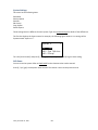
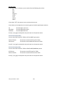
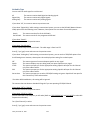
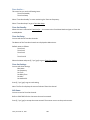
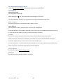
Power On
Press [
/
/
] for 1 second to turn on the scanner.
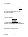
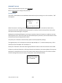
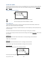
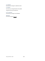
The scanner displays the opening screen and the copyright notice, and finally goes to the LAST MODE. The
last select GPS Display mode is also backed up.
Notes on the Last Mode:
LAST MODE means the mode when the scanner is turned off. It resumes Scan Mode,
Custom/Service/Quick Search Mode, Weather Mode, Close Call Only, Tone-Out Mode, each Hold
Mode, GPS Mode and Band Scope Mode for LAST MODE.
In ID Search Hold Mode if ID has already been registered, LAST MODE will be ID Search Hold Mode.
If ID has not been registered yet, LAST MODE will be Scan Mode.
Review Location Mode is set to normal Scanner Mode (not GPS Mode).
Uni den Bearcat
BCD396XT
Di gi tal Trunki ng
Dynami c Scanni ng
Copyri ght 2009
Uni den Ameri ca
Corp. All Ri ghts
Reserved.
Opening Screen
Friday, November 07, 2008
Copyright Notice Screen
25
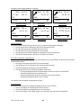
Volume and Squelch Control
Volume and Squelch can be adjusted by rotating the [Scroll Control] in the following modes: Scan Mode,
Scan Hold Mode, Search Mode, Search Hold Mode, Tone-Out Mode, Weather Scan Mode, Close Call Only
Mode, Band Scope Mode, Band Scope Hold Mode.
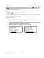
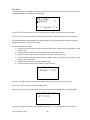
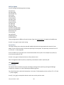
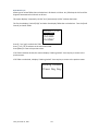
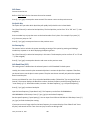
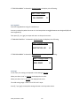
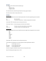
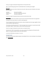
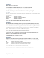
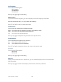
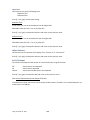
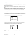
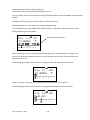
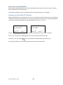
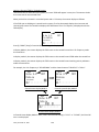
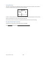
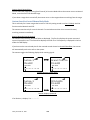
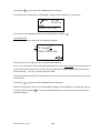
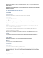
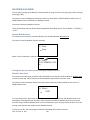
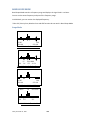
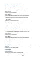
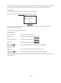
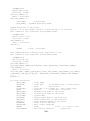
Volume Adjust Mode
To adjust the volume level, press [Scroll Control]. When the volume level indicator appears, rotate [Scroll
Control] to change the volume level.
You can set the volume level from 0 to 15.
PRI
3. 87
System 1
25. 0000MHz
AM
VOLUME LEVEL
Battery Voltage
11
Volume Adjustment
Press [Scroll Control] again or wait for 10 seconds to quit from the volume level control mode.
Press [Function] + [Scroll Control] to enter the P25 Condition Mode.
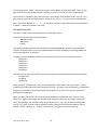
Squelch Adjust Mode
To adjust the squelch level, press [Function] + [Scroll Control]. When the squelch level indicator appears,
rotate [Scroll Control] to change the squelch level.
The squelch level can set from 0 to 15.
PRI
3. 87
System 1
25. 0000MHz
AM
SQUELCH LEVEL
Battery Voltage
11
Squelch Adjustment
Press [Scroll Control] key again or wait for 10 seconds to quit from the squelch level control mode.
Press [Function] + [Scroll Control] key to enter the P25 Condition Mode.
Friday, November 07, 2008
26
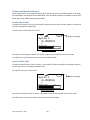
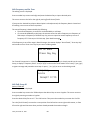
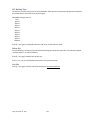
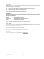
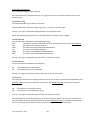
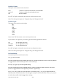
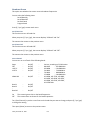
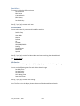
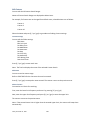
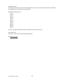
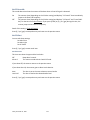
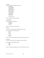
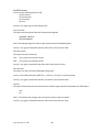
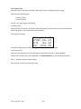
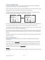
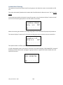
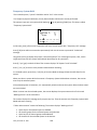
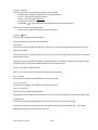
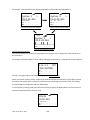
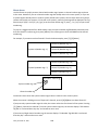
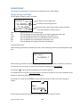
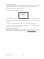
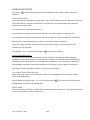
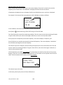
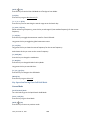
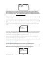
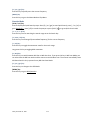
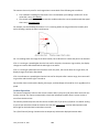
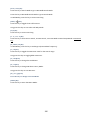
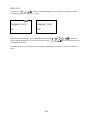
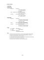
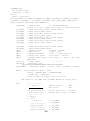
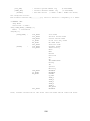
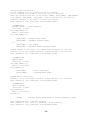
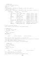
P25 Condition Mode
Press [Function] + [Scroll Control] key to go to P25 Condition mode in Volume / Squelch Adjust mode.
You can see the current status of APCO decoding and the threshold values in this mode.
PRI
3. 87
Battery Voltage
System 1
25. 0000MHz
NFM
ERR: 14
T 1. 25
P25
8 AUTO
1. 58
1. 80
P25 Condition
T 1. 25 1. 58 1. 80 indicates the threshold voltage. The specific values will be determined by your setup.
The number following ERR: indicates the APCO decoder error rate.
This number preceding AUTO shows threshold value.
Press [Scroll Control] key or [Function] + [Scroll Control] key to quit the P25 Condition Mode. This mode
doesn't have a time-out.
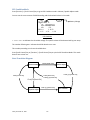
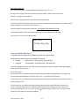
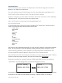
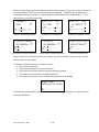
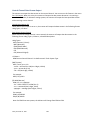
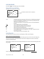
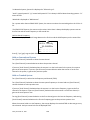
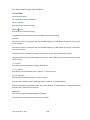
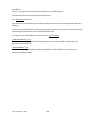
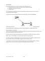
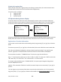
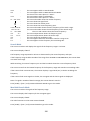
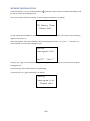
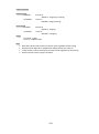
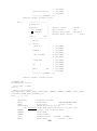
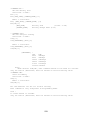
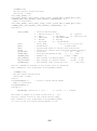
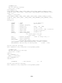
State Transition Diagram
Push [Scroll Ctrl]
Normal Mode
Push [Scroll Ctrl]
Push [F]+[Scroll Ctrl]
Push [Scroll Ctrl]
Push [F]+[Scroll Ctrl]
Push [F]+[Scroll Ctrl]
Squelch Adjust
Friday, November 07, 2008
Volume Adjust
27
Push [F]+[Scroll Ctrl]
P25 Condition
Menu Mode
General Operations
Key Operation
To enter the Menu Mode: Press [Menu]
To select a Menu item: Turn [Scroll Control]
To select a Menu item or input data: Press [E / yes / gps] or tap the [Scroll Control]
To Return to the previous: Press [Menu]
To exit from Menu Mode:
Press [Scan / srch] to go to Scan Mode
Press [Hold /
] to go to Scan Hold Mode
Press [Menu] at Top Menu to return to previous mode
Press [L/O] to exit Menu and return to previous mode
Notes:
Tapping the [Scroll Control] can be used instead of [E / yes / gps] in Menu Mode or at various
prompts.
NEXT item is a lower item in this document. Therefore, the next item of the lowest Item is highest
item.
Menu items are described as the bold letter in this specification.
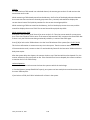
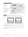
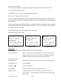
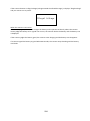
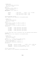
Display Format in Menu Mode
The Menu Item screen is four-line mode.
The first line displays the Menu Item Name and the selection items are displayed below.
For example, the Menu display of a channel modulation setting is as follows.
Set Modulati on
Auto
AM
NFM
Select an item by turning [Scroll Control] until the item is highlighted, then pressing [E / yes / gps].
Friday, November 07, 2008
28
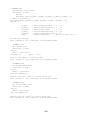
Edit Name
The editing cursor is displayed. Turn [Scroll Control] to choose the character and the cursor stays at the
highlighted position. The display is the following.
Edi t Name
System 1
C
4 ← cursor → 6
Press [4 / LEFT / ifx] to move the cursor to the left and [6 / RIGHT / disp] to move it to the right.
Press [. / no / pri] once to erase one character with the cursor. Press it twice to erase all characters.
If the inputted name exists already in the same category, the scanner beeps Confirmation Tone and
displays "Name Exists" and "Accept? (Y/N)".
By “Same category” we mean:
A system name is the same as a service search range name, custom search range name or other
system name.
A group name is the same as another group name in the same system.
A channel name is the same as another channel name in the same group.
A custom search range name is the same as a system name, service search range name or other
custom search range name.
A SAME name is the same as another SAME name.
A Tone-Out name is the same as another Tone-Out name.
Name Exi sts
Accept? (Y/N)
Press [E / yes / gps] to ignore the message and set the name. Then it proceeds to next step.
Press [. / no / pri] to return to the name editing state.
Note: If the user name has no character, the scanner prompts "Set Default Name" and "OK? (Y/N)".
Set Default Name
OK? (Y/N)
Press [E / yes / gps] to set Name to the default name. Press [. / no / pri] to return to name editing.
Friday, November 07, 2008
29
Edit Frequency and Set Tone
The editing cursor is displayed.
Press a number key to enter each digit and press the decimal key to input a decimal point.
The cursor moves to the left or the right by turning [Scroll Control] knob.
If you press the decimal key when a decimal point is already entered, the frequency data is cleared and
the editing cursor moves to the first position.
The stored frequency is determined by the following:
The entered frequency is stored if it can be divided by a valid step.
If it cannot be divided by a valid step, the scanner stores the nearer frequency at a frequency of
5kHz step or a frequency of 6.25kHz step. So, you must input the correct frequency to store a
frequency of 7.5 kHz step or 8.33 kHz step. (See: Band Coverage)
If the frequency is out of the range in Band Coverage, the scanner displays "Out of Band", “Press Any Key”
and sounds an Error Tone. Press any key to return to editing mode.
Out of Band
Press Any Key
For Channel Frequencies in conventional System, if the entered frequency is already stored into the same
Group, it displays "Frequency Exists" “Accept? (Y/N)” and sounds a Confirmation Tone. Press [E / yes / gps]
to ignore message and proceed to next step. Or press [. / no / pri] to return to the editing mode.
Frequency
Exi sts
Accept? (Y/N)
Edit Talk Group ID
Decimal TGID edit
The editing cursor is displayed.
Press a number key to enter the TGID and press the decimal key to enter a hyphen. The cursor moves to
the right by entering a number or hyphen.
Press the decimal key first to set "i" for I-Call entries. Then press the number keys to enter the I-Call ID.
Turn the [Scroll Control] to move the cursor position from left end to next to right end character, or from
left end to right end character when you have already entered the maximum length.
Friday, November 07, 2008
30
Hexadecimal TGID edit
Turn the [Scroll Control] to select Hexadecimal characters from “0” to “F”,
Press [4 / LEFT / ifx] to move the cursor left or press [6 / RIGHT / disp] to move cursor right.
Press [E / yes / gps] to set the Hex ID.
Note: You can change the TGID format in Set ID Format (DEC/HEX)
If you press the decimal key when there are already an acceptable number of hyphens, the TGID is cleared
and the editing cursor moves to the first position.
Note: For details of TGID formats, please see: TGID FORMAT FOR TRUNKED SYSTEM.
If the entered TGID is invalid, the scanner beeps an Error Tone and displays "Bad TGID".
Press any key to return to the editing mode.
Bad TGI D
Press Any Key
Notice of Location Data Input
Use WGS84 (World Geodetic System 1984) for latitude and longitude input.
The acceptable range of latitude and longitude is as follows.
Latitude
: 90º00'00.00 S - 00º00'00.00 N - 90º00'00.00 N
Longitude
: 180º00'00.00 E - 000º00'00.00 W - 180º00'00.00 W
The actual navigation distance may differ from the calculated one when a latitude exceeding 85 degrees
(either North or South) is used.
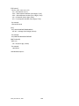
Error Messages
If the scanner tries to create a new System/Location/Site/Group/Channel/TGID when it is already at the
limit of System/Group/Channel, it displays “Over Limit”. (See: Memory Architecture)
If the scanner tries to create a new System/Location/Site/Group/Channel/TGID when the memory is full, it
displays “Memory Full”.
If the scanner tries to create a new System/Location/Site/Group/Channel/TGID when the memory is
broken, it displays “Memory Error”. When the scanner displays this message, you must initialize the
memory by pressing [2 / sr2] + [9 / mod] + [Hold /
repair fault if this does not correct the problem.
Friday, November 07, 2008
] while turning on the scanner. The scanner has a
31
Top Menu
Press [MENU] key to go to Menu Mode. Top Menu has the following items.
Program System
Program Location
Srch/CloCall Opt
Search for...
Close Call
Priority ID Scan
WX Operation
Tone-Out for …
Wired Clone
Settings
Turn the [Scroll Control] to select items and press [E / yes / gps] to go to the selected item.
Press [Menu] to exit from Menu Mode.
Program System
You can select a System for editing or create a new System.
Names of existing Systems are displayed as Menu Items. These systems are sorted by the order in which
they were created. "New System" is displayed as the last menu item.
Note: When no systems have been programmed, only "New System" appears.
The limit of Systems is 500. So, if you try to select "New System" when there are already 500 Systems, the
scanner displays "Over Limit" and sounds an Error Tone. Then it returns to Top Menu.
Over Li mi t
Press Any Key
Select the System Name and press [E / yes / gps] to go to the Systems Settings Menu. (See: System
Settings)
If you select a protected system, “Protected System Access Not Allowed Press Any Key” is displayed and
an Error Tone sounds.
Select "New System" and press [E / yes / gps] to create a new System.
Friday, November 07, 2008
32
Creating a New System
You can create up to 500 systems.
To create a new system, select the system type from the following items.
P25
Select for P25 Standard Trunk or One-Freq system
MOT
Select for any Motorola Type system
EDCS
Select for EDACS WIDE/NARROW or EDACS SCAT system
LT
Select for an LTR system
Conventional Select for a non-trunked system.
If you select a P25 type, you need to select more system type information from the following:
Standard Trunk
Select for a P25 Standard Trunk system
One-Freq Trunk
Select for a P25 One-Freq Trunk system
If you select an EDCS type, you need to select more system type information from the following:
WIDE/NARROW
Select for an EDACS WIDE/NARROW system
SCAT
Select for an EDACS SCAT system
Once you select the system type, the scanner prompts "Confirm?" and "Yes="E" / No="."".
Confi rm?
Yes=”E ” / N o = ” . ”
Press [E / yes / gps] to confirm, and the system will be created.
Press [. / no / pri] to reject and return to the Menu of Select System.
When the System is created, the scanner assigns a default System name of "System xxx T" to the new
System. (xxx: 1-3 digits sequential number / T: initial of type; P25=”P”, MOT="M", EDACS="E", LTR="L",
Conventional="C"). Then, the scanner goes go to Edit System Menu.
Note: Once a system has been created, the system type setting cannot be changed.
Friday, November 07, 2008
33
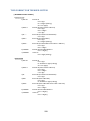
System Settings
This menu has the following items.
Edit Name
Edit Sys Option
Edit Site
Edit Group
Copy System
Delete System
These setting items are different for each System Type. See System Settings for details of the differences.
The first line displays the System name. For example, the following figure shows it is in settings of the
System named "System 1 C".
System 1
C
Edi t Name
Edi t Sys Opti on
Edi t Group
Turn the [Scroll Control] and press [E / yes / gps] or tap the [Scroll Control] to go to each setting.
Edit Name
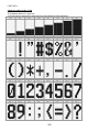
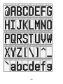
You can name the system. Refer to FONT DATA for the characters that can be entered.
Press [E / yes / gps] to accept the name entered. The scanner returns to the previous menu.
Friday, November 07, 2008
34
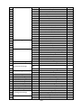
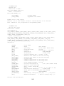
Edit Sys Option
You can change the following System settings.
Set Quick Key
Set Startup Key
Set Number Tag
Set Lockout
Set Hold Time
ID Scan/Search
Set Delay Time
Edit Fleet Map
Priority ID Scan
Set Status Bit
Set End Code
Emergency Alert
Set ID Format (DEC/HEX)
Set ID Format (AFS/DEC)
Rvw ID:Srch L/O
Clr All L/O IDs
Set Audio AGC
P25 Waiting Time
P25 NAC Option
These setting items are different for each System Type. See System Option for details of the difference.
Press [E / yes / gps] to enter each setting.
Set Quick Key
This option allows you to select key that will rapidly lock/unlock the System when the scanner is Scan
Mode. Turn the [Scroll Control] to select the Quick Key for the System. The Quick Key can be set from “0”
to “99” and “.”(= Not assigned).
Press a number key to jump the cursor to the head number of ten's place. For example if you press [2 /
sr2], the cursor jumps to “20”.
Press [E / yes / gps] to accept and return to the previous menu.
Note: The highest number of priority is Quick Key 1 and lowest number is Quick Key 90.
(See: Scanning Order.)
Set Startup Key
The scanner locks or unlocks the system according to setting of this option by pressing and holding a
number key at power-on or while displaying the Opening Screen.
Turn [Scroll Control] to select the Startup Key in this menu. The Startup Key can be set from “0” to “9” and
“.”(= Not assigned).
Press [E / yes / gps] to accept the selection and return to the previous menu.
Friday, November 07, 2008
35
Set Number Tag
The System Number Tag can be set in this menu.
Press a number key to input the number tag. Press [. / no / pri] to clear the input.
Press [E / yes / gps] to accept the setting and return to the previous menu.
Note: The valid setting range is from 0 to 999. Blank means a number tag not assigned.
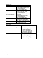
Set Lockout
This option allows you to lock or unlock the current system. When the system is locked out, the scanner
does not check it.
Unlocked
Temporary L/O
Lockout
The system is unlocked.
The system is temporarily locked out.
The system is locked out.
Press [E / yes / gps] to accept the selection and return to the previous menu.
Set Hold Time
This setting determines the minimum time the scanner is forced to hold and scan System Channels before
moving to the next System, even if there is no traffic on the Channels. You can set it from 0 to 255 seconds
by pressing a number key.
Press [E / yes / gps] to accept the entry and return to the previous menu.
If you enter over “255” for the Hold Time, the scanner prompts "Out of Range" and "Set Max? (Y/N)".
When [E / yes / gps] is pushed, maximum value 255 will be set.
It returns to the edit state, if you press [. / no / pri].
Note: The scanner will check all unlocked Channels at least 1 time before moving to the next system,
independent of whether the hold time has been set or not.
ID Scan/Search
This setting determines how the scanner scans trunked Systems.
ID Scan
ID Search
The scanner only stops on TGIDs that have been programmed and not locked out.
The scanner stops on any TGID that is not locked out.
Press [E / yes / gps] to set the setting and return to the previous menu.
Friday, November 07, 2008
36
Set Delay Time
This setting controls how long the scanner stays on a transmission before resuming scanning. If you select
a positive value, the scanner will hold on the channel for that duration after the carrier drops before
resuming scanning. If you select a negative value, the scanner will stay on a transmission until the carrier
drops or until the selected time elapses, whichever is shortest.
Turn [Scroll Control] to select the delay time setting from the following list:
-10 sec
-5 sec
-2 sec
0 sec
1 sec
2 sec
5 sec
10 sec
30 sec
Then press [E / yes / gps] to accept and return to the previous menu.
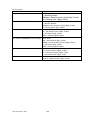
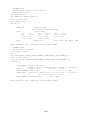
Edit Fleet Map
Motorola 800 Type I/Hybrid Systems require a Fleet Map that sets specific Fleet - SubFleet parameters.
There are 16 preset Fleet Maps listed in PRESET FLEET MAP that you can choose, and these are usually a
good place to start when setting up a Type I/Hybrid System. If you choose a preset map and still have
difficulty following complete conversation, then you will have to program a Custom Fleet Map.
Note: A Hybrid System is simply a Type I System with some blocks designated as Type II blocks. Select Size
Code 0 to treat the block as Type II and select others to treat as Type I.
You can select from "Preset" and "Custom".
Preset
Custom
Preset
If "Preset" is selected by pressing [E / yes / gps], you need to select from 16 preset Fleet Maps.
Preset 1
Preset 2
:
Preset 16
Press [E / yes / gps] to select one of the 16 preset Fleet Maps and return to the previous menu.
Friday, November 07, 2008
37
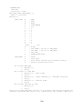
Custom
On the other hand, if "Custom" is selected, then you are prompted to enter the Fleet Map information.
You need to set Size Codes to all Blocks in order.
There are 8 Blocks from "Block 0" to "Block 7" and 15 Size Codes from "Size Code 0" to "Size Code 14".
In this selection, first Line displays the Block number and after second lines displays the Size Code.
Size Code 0
Size Code 1
Size Code 2
:
Size Code 14
Turn [Scroll Control] to select the Size Code. Press [E / yes / gps] to set the Size Code and proceed to the
next Block setting. And press [Menu] to go back to the previous one.
Press [E / yes / gps] at the last Block to return to the previous menu with the current selection.
Press [Menu] at Block 0 to return to the previous menu. However, Size Codes once selected by pressing [E
/ yes / gps] are not canceled.
Motorola 800 Type I and Type II:
Select Custom and set all blocks to Size Code 0. The scanner treats this System as Motorola Type II. In
other cases, it treats the System as Motorola Type I.
Note: If you change the Fleet Map setting, the ID display format will also change.
Priority ID Scan
This setting controls how the scanner treats Priority IDs.
You can select the following items.
On
Off
The scanner scans all unlocked IDs and also checks Priority IDs.
The scanner provides no special treatment for Priority IDs.
Press [E / yes / gps] to accept the selection and return to the previous menu.
Set Status Bit
This setting determines how the scanner treats the status bits.
Yes
Ignore
The scanner pays attention to the status bits in the TGID.
The scanner ignores status bits in the TGID.
Press [E / yes / gps] to accept the entry and return to the previous menu.
Friday, November 07, 2008
38
Set End Code
This setting determines how the scanner treats the transmission end code.
Analog
The scanner pays attention to the analog transmission end code.
Analog+Digital The scanner pays attention to both analog and digital transmission end code
Ignore
The scanner ignores the transmission end code and waits for carrier drop.
Press [E / yes / gps] to accept the selection and return to the previous menu.
Emergency Alert
The following options can be set in this menu.
Set Alert Tone
Set Alert Light
Press [E / yes / gps] to enter the setting.
Set Alert Tone
If “Set Alert Tone” is selected, user can determines how the scanner treats the Talk Group that set with
emergency flag.
Off
Alert1-9
The scanner ignores the emergency flag.
The scanner sounds the Emergency Alert Tone when any Talk Group goes active with the
emergency flag set.
When you select “Off”, the scanner returns to the previous menu.
When you select “Alert1-9”, the scanner goes to the Alert Level selection.
Auto
Level1-15
The alert is set to the same volume as normal audio.
The alert is fixed to the selected audio level.
Press [E / yes / gps] to accept the entry and return to the previous menu.
Friday, November 07, 2008
39
Set Alert Light
If “Set Alert Light” is selected, you can select from the following alert colors:
Off
Blue
Red
Magenta
Green
Cyan
Yellow
White
If you select “Off”, the scanner returns to the previous menu.
If you select an alert light color, the scanner goes to the Alert Light Pattern selection.
On
Slow Blink
Fast Blink
The alert light is set to on
The alert light blinks slowly
The alert light blinks fast
Press [E / yes / gps] to accept the entry and return to the previous menu.
Set ID Format (DEC/HEX)
You can select the format for TGIDs on P25 and MOT type system.
Decimal Format
Hex Format
The scanner uses decimal format for TGIDs.
The scanner uses hexadecimal format for TGIDs.
Press [E / yes / gps] to accept the entry and return to the previous menu.
Set ID Format (AFS/DEC)
You can select the format for TGIDs on EDACS WIDE/NARROW systems.
AFS Format
Decimal Format
The scanner uses AFS format for TGIDs.
The scanner uses decimal format for TGIDs.
Press [E / yes / gps] to accept the entry and return to the previous menu.
Friday, November 07, 2008
40
Rvw ID:Srch L/O
Allows you to review TGIDs that are locked out in ID Search or ID Scan. Any TalkGroup in this list will be
skipped if encountered in ID Search or ID Scan.
This option displays “temporarily L/O IDs” and “permanently L/O IDs” without distinction.
The first Line displays "Unlock?(Y/N)" and other lines display TGIDs that are locked out. Turn the [Scroll
Control] to choose TGIDs.
Unlock?(Y/N)
I D: 12340
I D: 11111
I D: 34567
Press [E / yes / gps] to unlock the TGID.
Press [. / no / pri] to advance to the next locked TGID.
Press [Menu] to return the previous menu.
If no TGIDs have been locked, the scanner displays "Nothing Locked". Press any key to return to the
previous menu.
If all TGIDs are unlocked, it displays "Nothing Locked". Press any key to return to the previous menu.
Nothi ng Locked
Press Any Key
Friday, November 07, 2008
41
Clr All L/O IDs
Selecting this causes the scanner to prompt "Confirm ?" and "Unlock All(Y/N)".
Confi rm?
Unlock All(Y/N)
Press [E / yes / gps] to unlock all TGIDs.
Press [. / no / pri] to cancel this selection.
The scanner returns to the previous menu.
If all TGIDs are unlocked, it displays "Nothing Locked". Then press any key to return to previous menu.
Nothi ng Locked
Press Any Key
Set Audio AGC
When Audio AGC function is “On”, the scanner judges the volume level and changes the volume
automatically.
You can turn either Analog or Digital audio “On” or “Off”.
Analog :
Digital :
On / Off
On / Off
On
Off
Audio AGC is on.
Audio AGC is off.
Turn [Scroll Control] to focus the cursor on the item. Press [E / yes / gps] to change the setting on / off and
press [Menu] to return to the previous menu.
Friday, November 07, 2008
42
P25 Waiting Time
The feature is used to set a wait time for P25 decode. After receive a transmission the scanner will wait for
the set duration to check if there is any P25 signal.
Selectable waiting times are:
0 ms
100 ms
200 ms
300 ms
400 ms
500 ms
600 ms
700 ms
800 ms
900 ms
1000 ms
Press [E / yes / gps] to accept the selection and return to the previous menu.
P25 NAC Option
This menu is used to set P25 NAC (Network Access Code) option for the P25 One-Freq Trunk systems. You
can select from the following items.
Search
Set P25 NAC
The scanner search for all the P25 NAC.
The scanner uses the programmed P25 NAC
When you select “Search”:
The scanner returns to the previous menu.
When you select “Set P25 NAC”:
Press the number key to enter P25 NAC, valid range is from 0 to FFF hex.
Press [E / yes / gps] to set and return to the previous menu.
If out of range, the message “Out of Range” and “Press Any Key” will be shown with error tone.
Edit Site
See Program Site.
Edit Group
See Program Group.
Friday, November 07, 2008
43
Copy System
You can copy the System and all associated settings by select this menu item. The scanner prompts you for
a new System Name.
New Sys Name?
4 ← cursor → 6
Press [E / yes / gps] to copy the System with the entered System name.The scanner goes to the System
Settings menu with the new System active.
Note: This operation also copies all sites, Groups and Channels belonging to the System.
Delete System
You can delete the current system and all associated settings by select this menu item. The scanner
prompts "Confirm Delete?" to confirm deletion.
Press [E / yes / gps] to delete the current system.
Press [. / no / pri] to cancel deletion and return to the previous menu.
Note: If you confirm to delete the system, all site, all Groups and all Channel data belonging to the System
are also deleted.
Friday, November 07, 2008
44
Program Site
You can select an existing Site for editing or create a new Site. Site Names that already have been created
are displayed as Menu Items.
Sites are sorted in the order of the Site Quick Key (See: Set Quick Key) as 1, 2,…,0,11,…99, 90 and not
assigned. The order of Sites belonging to the same Quick Key is determined by the order in which they
were created. "New Site" is displayed as the last menu item.
Select “New Site” and press [E / yes / gps] to create a new site.
Note: At first, only "New Site" is displayed.
The limit of Sites in a system is 256. So, if you try to select "New Site" when there are already 256 Sites, the
scanner displays "Over Limit" and sounds an Error Tone.
Creating a New Site
Press [E / yes / gps] to create a new site. After a new site is created, the scanner assigns a default site
name of "Site xxx-yyy TTT".
xxx: System index number,
yyy:
1-3 digit sequential site index number,
TTT:
abbreviation for the site type, as follows.
MOT Type = "MOT"
EDACS WIDE/NARROW= “EDC”
LTR Type = “LTR”
P25 Standard Type = “P25”
P25 One-Freq Type = “1FQ”
Site Settings
The following site settings are possible:
Edit Name
Set Quick Key
Set Startup Key
Edit Band Plan (P25)
Edit Band Plan (Mot)
Set Site Type
Set Frequencies
Set Modulation
Set Attenuator
Set Lockout
Set Hold Time
Set C-Ch Only
Set LocationInfo
P25 Waiting Time
Delete Site
New Site
The items available are different for each Site Type. See Site Settings for details of the difference.
Turn [Scroll Control] knob and press [E / yes / gps] key to go to each setting.
Friday, November 07, 2008
45
Edit Name
You can name the site.
Refer to FONT DATA for the characters that can be entered.
Press [E / yes / gps] to accept the name entered. The scanner returns to the previous menu.
Set Quick Key
This option lets you select which Quick Key will rapidly lock/unlock the site in Scan Mode.
Turn [Scroll Control] to select the Site Quick Key. The Site Quick Key can be from “0” to “99” and “.”(= Not
assigned).
Press a number key to jump the cursor to the head number of ten's place. For example if you press [2 /
sr2], the cursor jumps to “20”.
Press [E / yes / gps] to accept and return to the previous menu.
Set Startup Key
The scanner locks or unlocks the system according to setting of this option by pressing and holding a
number key at power-on or while displaying the Opening Screen.
Turn [Scroll Control] to select the Startup Key in this menu. The Startup Key can be set from “0” to “9” and
“.”(= Not assigned).
Press [E / yes / gps] to accept the selection and return to the previous menu.
Edit Band Plan (P25)
This setting menu is shown when the selected system is a P25 Standard Trunked system.
Usually, the scanner stores the plan automatically when it receives the plan from a repeater. Therefore,
you do not have to set the plan in most systems. The plan must be set manually only when the repeater
doesn’t send the plan.
You can set 16 bands for a site. First, select the Band Plan number (“Select Plan”) by turning the [Scroll
Control]. The scanner displays the Band Plan number, the base frequency and the spacing frequency as
“n:xxx.xxxxx/y.yy”. (n : Band Plan number, xxx.xxxxx : the base frequency, y.yy : the space frequency)
Press [E / yes / gps] to select a band plan.
Input the base frequency (“Input Base Freq”). This frequency can be from 25.00000MHz to
1300.00000MHz at 5.0Hz steps. Press [E / yes / gps] to set the base frequency.
Set the space frequency (“Input Spacing”). You can input from 125Hz to 128.0kHz in 125Hz Steps. Press [E /
yes / gps] to finish the band plan setting.
If you enter an out of range value for the base frequency, the scanner displays “Out of Band” and “Press
Any Key” and sounds an Error Tone. Press any key to return to editing mode.
Friday, November 07, 2008
46
If you enter less than “125Hz”, the scanner prompts “Out of Range" and "Set Min? (Y/N)”. Press [E / yes /
gps] to set the minimum spacing frequency (125Hz). Or, press [. / no / pri] to return to editing state.
If you enter over “128.0kHz”, the scanner prompts "Out of Range" and "Set Max? (Y/N)". Press [E / yes /
gps] to set the maximum spacing frequency (128.0kHz). Or, press [. / no / pri] to return to editing state.
Note: The scanner displays “n:---------/----“ (n : Band Plan number) in Select Plan when the base frequency
is “0MHz”. It means the number is not used.
Edit Band Plan (Mot)
This menu is shown when the selected system is a MOT type system.
You can select one of three kinds of band plans:
800/900 Standard
800 Splinter
Custom
To properly track Motorola VHF and UHF systems and rebanded 800 MHz systems, you should select
“Custom” and enter what is known as the base frequencies (Lower and Upper), the spacing frequencies
and channel offsets for each System.
To select the custom Band Plan number, turn the [Scroll Control] to select its number from 1 to 6.
Band Plan 1
Band Plan 2
Band Plan 3
Band Plan 4
Band Plan 5
Band Plan 6
Then press[E / yes / gps] is pressed. You are then prompted to set the detailed information of band plan.
Set Base Freq
Set Offset
Set Spacing
When you select “Set Base Freq”, you are then prompted to “Input Lower” then “Input Upper”. Use the
number keys and decimal key to input frequencies. Press [E / yes / gps] to set the frequency. If the entered
frequency is out of band, “Out of Band” will be shown with an error tone. Press any key to go back to
editing the base frequency.
When you select “Set Offset”, you can set the channel offset for the band plan entry. You can set the
Offset from -1023 to +1023. Enter the absolute value using the number keys. If you input a value over
1023, “Out of Range” and “Set Max? (Y/N)” will be shown. Press [. / no / pri] to return to editing state.
Press [E / yes / gps] to set the value to maximum number (1023) and you will be prompted to “Select
Polarity”. Select “+ Polarity” or “- Polarity”, then press [E / yes / gps] to confirm the setting.
Friday, November 07, 2008
47
When you select ”Set Spacing”, the following spacing values can be selected:
5.00 kHz
6.25 kHz
10.00 kHz
12.50 kHz
15.00 kHz
18.75 kHz
20.00 kHz
25.00 kHz
30.00 kHz
31.25 kHz
35.00 kHz
37.50 kHz
40.00 kHz
43.75 kHz
45.00 kHz
50.00 kHz
55.00 kHz
56.25 kHz
60.00 kHz
62.50 kHz
65.00 kHz
68.75 kHz
70.00 kHz
75.00 kHz
80.00 kHz
81.25 kHz
85.00 kHz
87.50 kHz
90.00 kHz
93.75 kHz
95.00 kHz
100.00 kHz
Turn the [Scroll Control] to select. Press [E / yes / gps] to set the Spacing.
Note: If Base Freqs haven’t been set yet, the setting of Offset and Spacing will not be accepted.
For rebanded systems, the most likely settings for Base (Lower and Upper), Offset and Spacing in the table
are:
Band Plan Base Freq (Lower) Base Freq (Upper) Offset Polarity Spacing
1
851.025MHz
854.000MHz
440
+
25 kHz
2
851.0125MHz
868.9875MHz
0
+
25 kHz
Set Site Type
You can select the site type for EDACS WIDE/NARROW system.
Wide(Standard)
Narrow
EDACS wide site
EDACS narrow site
Press [E / yes / gps] to accept and return to the previous menu.
Set Frequencies
You can select a stored frequency or enter a new system frequency.
Frequencies already set are displayed as a Menu Item and "New Frequency" is displayed as the last one.
For example, if you have stored "851.0125MHz" and "868.9875MHz", the selectable items are as follows:
Sel Frequency
851. 0125MHz
868. 9875MHz
New Frequency
Note: At first, only "New Frequency" is displayed.
The limit of trunk frequencies in a site is 500 - 1000. You can store up to 1000 total TGID and trunk
frequencies. When it is over the limit, the scanner sounds an Error Tone.
Friday, November 07, 2008
48
If "New Frequency" is selected by pressing [E / yes / gps], the scanner skips the next selection. Then it goes
to Edit Frequency menu automatically to enter the frequency.
If you select a stored frequency and press [E / yes / gps], the scanner prompts for the next setting items.
Edit Frequency
Set Number Tag*
Set Lockout
Volume Offset (SCAT systems only)
Delete Frequency
New Frequency
Turn [Scroll Control] and press [E / yes / gps] to go to each setting.
*This setting is displayed only when the system type is "EDCS SCAT".
Edit Frequency
You can enter or edit the frequency by pressing the number keys and decimal key.
Press [E / yes / gps] to store the frequency.
The scanner does not allow frequency duplication in a System. If the entered frequency is already stored
into that System, the scanner sounds an Error Tone and displays "Frequency Exists".
Frequency Exi sts
Press Any Key
Then press any key to return to the editing mode.
Valid frequency ranges are in Band Coverage. If the entered frequency is out of range, the scanner sounds
an Error Tone and displays "Out of Band". And the scanner stays on this state.
If the type of System is EDACS WIDE/NARROW or LTR,the scanner prompts for a LCN (logical channel
number). Press [0 - 9] to enter the LCN.
Note: You can only enter the LCN suitable for each System type. EDACS: 1-30, LTR: 1-20.
Press [E / yes / gps] to store the LCN and return to the previous menu. The scanner does not allow LCN
duplication in a System. If the entered LCN is already stored, the scanner sounds an Error Tone and
displays "LCN Exists".
LCN Exi sts
Press Any Key
Friday, November 07, 2008
49
Set Number Tag
The channel Number Tag can be set in this menu.
Press a number key to input the number tag. Press [. / no / pri] to clear the input.
Press [E / yes / gps] to accept the setting and return to the previous menu.
Note: The valid setting range is from 0 to 999. Blank means a number tag not assigned.
This option is only shown when system type is EDACS SCAT.
Set Lockout
This option allows you to lock or unlock the current system. When the system is locked out, the scanner
does not check it.
Unlocked
Temporary L/O
Lockout
The system is unlocked.
The system is temporarily locked out.
The system is locked out.
Press [E / yes / gps] to accept the selection and return to the previous menu.
Volume Offset (SCAT systems only)
This option is used to set a volume offset for each site frequency. The feature can let you adjust the
volume level relative to other channels when the frequency is active. Setting level are:
-3
-2
-1
0
+1
+2
+3
Press [E / yes / gps] to accept the selection and return to the previous menu.
Delete Frequency
You can delete the current frequency and all associated settings by selecting this menu item. The scanner
prompts "Confirm Delete?" to confirm deletion.
Press [E / yes / gps] to delete the current frequency.
Press [. / no / pri] to cancel deletion and return to the previous menu.
New Frequency
Press [E / yes / gps] to create a new frequency and go to Set Frequencies.
Friday, November 07, 2008
50
Set Modulation
You can select the modulation from following settings.
Auto* The scanner uses the modulation normal for the frequency’s band.
NFM The scanner uses Narrowband FM demodulation.
FM
The scanner uses FM demodulation.
Press [E / yes / gps] to accept the entry and return to the previous menu.
*If the system type is “MOT”,”LT” or “EDCS SCAT”, when the default modulation of the frequency in Band
Defaults is not FM or NFM, the scanner will operate as FM.
Set Attenuator
You can attenuate RF reception on the frequency.
On
Off
The frequency will be attenuated.
The frequency will not be attenuated.
Press [E / yes / gps] to accept the selection and return to the previous menu.
Set Lockout
This option allows you to lock or unlock the current system. When the system is locked out, the scanner
does not check it.
Unlocked
Temporary L/O
Lockout
The system is unlocked.
The system is temporarily locked out.
The system is locked out.
Press [E / yes / gps] to accept the selection and return to the previous menu.
Set Hold Time
In Trunked Systems, this setting is applied only when a Control Channel can be received.
If no Control Channel can be received, the scanner goes to the next system immediately.
You change this setting from 0 to 255 seconds by pressing the number keys.
Press [E / yes / gps] to accept the entry and return to the previous menu.
If you enter over “255” for the Hold Time, the scanner prompts "Out of Range" and "Set Max? (Y/N)".
When [E / yes / gps] is pushed, maximum value 255 will be set.
It returns to the edit state, if you press [. / no / pri].
Friday, November 07, 2008
51
Set C-Ch Only
You can select how the scanner tracks Motorola Systems. (C-Ch means control channel.)
On
Off
The scanner can track Motorola System by entering only the system control channels. You will not
have to program the voice channels.
You need to enter the control channel and voice channels.
Press [E / yes / gps] to accept the entry and return to the previous menu.
Set LocationInfo
You can set the location data for the current site.
The setting items are:
Set Latitude
Set Longitude
Set Range
Set GPS Enable
Turn [Scroll Control] to select the item and Press [E / yes / gps] to go to the settings.
Set Latitude
Press the number keys to enter latitude data. Press any number key when the cursor is in the last position
to toggle between south latitude (S) and the north latitude (N).
Press [E / yes / gps] to accept and return to the previous menu.
If “DMS:DDD⁰MM’SS.ss” is selected in Set Pos Format, the display is the following.
Set Lati tude
00⁰00’ 00. 00 N
If “DEG:DDD.dddddd” is selected in Set Pos Format, the display is the following.
Set Lati tude
00. 000000
Friday, November 07, 2008
52
N
Set Longitude
Press the number keys to enter longitude data. Press any number key when the cursor is in the last
position to toggle between east longitude (E) and west longitude (W).
Press [E / yes / gps] to accept and return to the previous menu.
If “DMS:DDD⁰MM’SS.ss” is selected in Set Pos Format, the display is the following.
Set Longi tude
00⁰00’ 00. 00 W
If “DEG:DDD.dddddd” is selected in Set Pos Format, the display is the following.
Set Longi tude
00. 000000
W
Set Range
In this menu, the setting unit is determined by the setting in Set Unit.
When you select “mile” in Set Unit, the displayed unit will be mile.
When you select “km” in Set Unit, the displayed unit will be km.
The valid setting range is from 0.5 to 125.0, in 0.5 steps.
Press [E / yes / gps] to accept the setting and return to the previous menu.
Set GPS Enable
When this option is set to “On”, the scanner will control L/O status of this site by position information
received from a GPS.
On
Off
The L/O state of this site is automatically controlled by position information.
The L/O state of this site is not influenced by GPS.
Press [E / yes / gps] to accept and return to the previous menu.
Friday, November 07, 2008
53
P25 Waiting Time
The feature is used to set a wait time for P25 decode. After receive a transmission the scanner will wait for
the set duration to check if there is any P25 signal.
Selectable waiting times are:
0 ms
100 ms
200 ms
300 ms
400 ms
500 ms
600 ms
700 ms
800 ms
900 ms
1000 ms
Press [E / yes / gps] to accept the selection and return to the previous menu.
Delete Site
You can delete the current site and all associated settings by select this menu item. The scanner prompts
"Confirm Delete?" to confirm deletion.
Press [E / yes / gps] to delete the current site.
Press [. / no / pri] to cancel deletion and return to the previous menu.
New Site
Press [E / yes / gps] to create a New Site and goes to Creating a New Site.
Friday, November 07, 2008
54
Program Group
This menu lets you select a Channel Group for programming or create a new Channel Group.
Names of Groups already created are displayed as Menu Items. The order of Groups is sorted by setting of
Quick Key for Groups (See: Set Quick Key ) as 1, 2, 3, ... , 9, 0 and “.” (=Not assigned). The order of Groups
belonging to same Quick Key is determined by the assigned order. "New Group" is displayed as the last
item.
For example, there are two groups named "Group 1" and "Group 2", selectable items are as follows:
Group 1
Group 2
New Group
Select Group
Group 1
Group 2
New Group
Note: At first, only "New Group" is displayed.
The limit of Groups in a System is 20. So, if you try to select "New Group" when there are already 20
Groups in that System, the scanner displays "Over Limit" and sounds an Error Tone. Then it returns to
Group selection.
Select the Group Name or "New Group" and press [E / yes / gps] to go to the Group Settings Menu.
If the "New Group" is selected, the scanner appends a Group to the System with a default Group name of
"Group xx". (xx: 1-2 digits sequential number)
Group Settings
This menu has following group settings:
Edit Name
Set Quick Key
Edit Channel
Set LocationInfo
Set Lockout
Delete Group
New Group
Note: The name of the Group will be shown in the first line of the display.
Press [E / yes / gps] to go to each setting.
Edit Name
Here, you can name the Channel Group.
Refer to FONT DATA for the characters that can be entered.
Press [E / yes / gps] to accept the name entered. The scanner returns to the previous menu.
Friday, November 07, 2008
55
Set Quick Key
This option lets you select which Group Quick Key will rapidly enable/disable the Group when the scanner
is in the scanning mode.
Allowed settings are from 0 to 9 and not assigned. You can assign more than one Channel Group to the
same Quick Key.
Press [1 – 9, 0] to assign each number as a Group Quick Key.
Press [. / no / pri] to assign to no Group Quick Key.
Press [E / yes / gps] to accept and return to the previous menu.
Edit Channel
See: Program Channel.
Set LocationInfo
You can set location data for the current channel group so it is automatically locked and unlocked as you
change location (when using an external GPS).
You set the following items:
Set Latitude
Set Longitude
Set Range
Set GPS Enable
Turn [Scroll Control] to select an item to set and press [E / yes / gps] to go to the settings.
Set Latitude
Enter the latitude data using the number keys.
Press any number key when the cursor is in the last position to toggle between south latitude (S) and north
latitude (N).
Then press [E / yes / gps] to accept and return to the previous menu.
If “DMS:DDD⁰MM’SS.ss” is
display is the following.
selected in Set Pos Format, the
Set Lati tude
00⁰00’ 00. 00 N
Friday, November 07, 2008
56
If “DEG:DDD.dddddd” is selected in Set Pos Format, the display is the following.
Set Lati tude
00. 000000
N
Set Longitude
Enter the longitude data using the number keys.
Press any number key when the cursor is in the last position to toggle between west longitude (W) and
east longitude (E).
Then press [E / yes / gps] to accept and return to the previous menu.
If “DMS:DDD⁰MM’SS.ss” is selected in Set Pos Format, the display is the following.
Set Longi tude
000⁰00’00. 00
W
If “DEG:DDD.dddddd” is selected in Set Pos Format, the display is the following.
Set Longi tude
000. 0000
W
Set Range
In this menu, the setting unit depends on the setting in Set Unit.
When you select “mile” in Set Unit, the displayed unit is mile.
When you select “km” in Set Unit, the displayed unit is km.
The valid setting range is from 0.5 to 125.0 in 0.5 steps.
Press [E / yes / gps] to accept the setting and return to the previous menu.
Friday, November 07, 2008
57
Set GPS Enable
When this option is set to “On”, the scanner will control the L/O status of this channel group using position
information supplied from a connected GPS.
On
Off
The Channel Group’s L/O state is automatically controlled by position information.
The Channel Group’s L/O state is not influenced by GPS.
Press [E / yes / gps] to accept and return to the previous menu.
Set Lockout
This option allows you to lock or unlock the current channel group. When the channel group is locked out,
the scanner does not check it.
Unlocked
Temporary L/O
Lockout
The channel group is unlocked.
The channel group is temporarily locked out.
The channel group is locked out.
Press [E / yes / gps] to accept the selection and return to the previous menu.
Delete Group
You can delete the current channel group and all associated settings by select this menu item. The scanner
prompts "Confirm Delete?" to confirm deletion.
Press [E / yes / gps] to delete the current channel group.
Press [. / no / pri] to cancel deletion and return to the previous menu.
New Group
Press [E / yes / gps] to create a new group and go to Group Settings.
Friday, November 07, 2008
58
Program Channel
You can select a Channel for programming or add a new Channel.
Names of Channels already added are displayed as Menu Items. The order of Channels is sorted by created
or pasted order. "New Channel" is displayed as the next to last Channel. "Paste Channel" will be displayed
as the last item if a Channel has previously been copied from a compatible (same typed) System / Site.
For example, there are the Channel named "Channel A" and a Channel was copied, selectable items are as
follows:
Select Channel
Channel A
New Channel
Paste Channel
Note: At first, only "New Channel" is displayed.
For conventional systems, the limit of Channels for one system is 1000. So, if you select “New Channel”
and enter a frequency when there are already 1000 channels in the system, the scanner displays "Over
Limit" and sounds an Error Tone. Then it returns to channel selection.
For trunked Systems, the limit of Channels for one system is 500. So, if you select "New Channel" and enter
a TGID when there are already 500 Channels in the system, the scanner displays "Over Limit" and sounds
an Error Tone. Then it returns to Channel selection.
The limit of Channels and System frequencies is 25000. If you select "New Channel" and enter the
frequency or TGID when there are already 25000 Channels and System frequencies, the scanner displays
"Over Limit" and sounds an Error Tone. Then it returns to Channel selection.
Select the Channel Name and press [E / yes / gps] to go to the Channel Settings Menu.
Select "Paste Channel" and press [E / yes / gps] to paste the Channel. All settings are copied, then the
scanner goes to the Channel Settings Menu.
If the "New Channel" is selected by pressing [E / yes / gps], you need to enter the frequency for a
conventional System’s Channel or the TGID for a trunked system Channel.
Input Frequency:
You must enter a frequency.
Note: Please see: Band Coverage for acceptable frequencies.
Press [E / yes / gps] to set the frequency. The channel name is set to the frequency as a default name as
"xxxx.xxxxMHz". Then the scanner goes to the Channel Settings Menu.
Press [Menu] to return to the previous selection and cancel adding a Channel.
Friday, November 07, 2008
59
Input TGID:
You must enter a TGID.
You can input only a TGID in the format suitable for the site type.
Motorola Type ID (Decimal Format ID) :
When the custom Fleet Map setting for a MOT system is not all Size Code 0 for Blocks, the scanner treats
the System as a Motorola Type I.
Press the number keys to enter the Block number, Fleet number and SubFleet number.
Press the decimal key to enter a hyphen.
Note: 1 digit Block number, 2 - 3 digits Fleet number, hyphen and 1 - 2 digits SubFleet number.
When the set Preset Fleet Map or custom Fleet Map has all Blocks with Size Code 0, the scanner treats the
System as a Motorola Type ll.
Press the number keys to enter the TGID.
Note: Numbers only (up to 5 digits)
Motorola Type ID (Hex Format ID) :
Turn [Scroll Control] to select Hex character from “0” to “F”.
Press [4 / LEFT / ifx] or [6 / RIGHT / disp] to move cursor left or right.
Press [E / yes / gps] to set the Hex ID.
Note: When the custom Fleet Map setting set to Size Code 0 for all Blocks, the scanner treats the System
as a Motorola Type I or Hybrid system. In these cases Hexadecimal input will be treated as same as
Decimal ID. (see FLEET MAP for detail)
E.g. If you enter “1”,”2” as a Type l Hex ID, it will be treat as 12, not 0x12.
P25 Type ID (Decimal Format ID) :
For P25 Standard Trunk sites or One-freq Trunk systems.
Press the number keys to enter the TGID.
Note: Numbers only(up to 8 digits)
P25 Type ID (Hex Format ID) :
Turn [Scroll Control] to select Hex character from “0” to “F”.
Press [4 / LEFT / ifx] or [6 / RIGHT / disp] to move cursor left or right.
Press [E / yes / gps] to set the Hex ID.
Friday, November 07, 2008
60
EDACS ID :
For EDCS Wide/Narrow systems.
Press the number keys to enter the Agency number.
Press the decimal key to enter a hyphen.
Press the number keys to enter the Fleet number and SubFleet number.
Note: Agency number (00 - 15), hyphen, Fleet number (00 - 15) and SubFleet number (0 - 7)
The scanner does not accept all zero ID ("00-000").
You can omit the SubFleet number as a wildcard.
You can omit Fleet numbers and SubFleet numbers as wildcards.
LTR ID :
For LTR systems.
Press the number keys to enter the Area code, Home repeater and User ID.
Note: 6 digit numbers; Area code (0 or 1), Home repeater (01 - 20), User ID (000 - 254)
I-Call (Motorola, EDACS, P25) :
For any MOT System, EDCS Wide and Narrow, P25 Standard Trunk or P25 One-Freq Trunk system.
First, press the decimal key to enter "i" for I-Call. Then press the number keys to enter the ID.
Note: For details of TGID format, please see: TGID FORMAT FOR TRUNKED SYSTEM.
Press [E / yes / gps] to set the TGID. The Channel Name is set to the TGID as default name as "ID:xxxx".
Then the scanner goes to the Channel Settings Menu.
Press [Menu] to return to the previous selection and cancel adding a Channel.
Friday, November 07, 2008
61
Channel Settings
The following settings are available for channels.
Edit Name
Edit Frequency
Edit TGID
Set Audio Type
Set Number Tag
Set Modulation
Set Attenuator
Set Priority
Set Alert
Set Lockout
Volume Offset
Copy Channel
Delete Channel
New Channel
The specific settings available depend on the current system type.
See Channel Settings for details of the differences.
Note: The first Line in the display shows the name of the Channel in Menu Display.
Edit Name
You can provide a name for the channel.
Refer to FONT DATA for the characters that can be entered.
Press [E / yes / gps] to accept the name entered. The scanner returns to the previous menu.
Edit Frequency
If you select to edit the frequency, the scanner displays the current frequency in edit mode.
See Edit Frequency.
Edit TGID
If you select to edit the TGID, the scanner displays the current ID. You can use the keypad to change the ID.
When you press [E / yes / gps] to accept, the scanner checks for valid data and returns to the previous
menu.
If the ID is invalid, the scanner shows “Bad TGID” and “Press Any Key” and sounds an error tone. Press any
key to return to the editing state.
Friday, November 07, 2008
62
Set Audio Type
You can select an audio type for each channel.
All
Digital Only
Analog Only
The scanner receives both Digital and Analog signals.
The scanner receives only Digital signals.
The scanner receives only Analog signals.
If you select “All”, the scanner returns to previous menu.
If you select “Digital Only” while setting a conventional system, you can set the P25 NAC (Network Access
Code) option from the following items. However, these options are not shown for trunked systems.
Search
Set P25 NAC
The scanner searches for all the P25 NACs.
The scanner search for the programmed P25 NAC.
If you select “Search”:
The scanner returns to the previous menu.
If you select “Set P25 NAC”:
Use the number keys to enter a P25 NAC. The valid range is from 0 to FFF.
Press [E / yes / gps] to set and return to the previous menu.
If you select “Analog Only” while setting a conventional system, you can set the CTCSS/DCS options from
the following items. However, these options do not display when setting for trunked system.
Off
Search
CTCSS
DCS
Set Lockout
The scanner ignores all tones and opens squelch on any signal.
The scanner displays any tone being used, but opens squelch on any signal.
The scanner prompts you for the appropriate setting. Squelch will open for this Channel
only if the code matches.
The scanner prompts you for the appropriate setting. Squelch will open for this Channel
only if the code matches.
The scanner prompts you to select CTCSS/DCS settings to ignore. Squelch will not open for
this Channel only if the code matches.
*For AM or WFM modulation, this setting will be ignored.
The scanner does not detect or decode P25 signals if you are operating CTCSS/DCS Search.
If you select “Off” or “Search”:
The scanner returns to the previous menu.
If you select “CTCSS” or “DCS”:
You can select the CTCSS frequency or DCS code. (Refer to CTCSS FREQUENCY and DCS CODE for selectable
frequencies and codes.)
Turn [Scroll Control] to select.
Press [E / yes / gps] to set and return to the previous menu.
Friday, November 07, 2008
63
If you select “Set Lockout”:
You can select a CTCSS or DCS for lockout.
Turn [Scroll Control] to select and press [E / yes / gps] key to lock it out. Then the scanner returns to the
previous menu.
Set Number Tag
The Channel Number Tag can be set in this menu.
Press a number key to input the number tag. Press [. / no / pri] to clear the input.
Press [E / yes / gps] to accept the setting and return to the previous menu.
Note: The valid setting range is from 0 to 999. Blank means a number tag not assigned.
Set Modulation
You can select the modulation from the following settings.
Auto
The scanner uses the modulation normal for the frequency’s band. (See: Band Defaults)
AM
The scanner uses AM demodulation.
NFM
The scanner uses Narrowband FM demodulation.
FM
The scanner uses FM demodulation.
WFM
The scanner uses Wideband FM demodulation.
FMB
The scanner uses FM Broadcast demodulation.
Press [E / yes / gps] to accept the entry and return to the previous menu.
Set Attenuator
You can attenuate RF reception on the frequency.
On
Off
The frequency will be attenuated.
The frequency will not be attenuated.
Press [E / yes / gps] to accept the selection and return to the previous menu.
Set Priority
This option sets the Channel as a Priority Channel. You can set this On for each Channel independently. See
PRIORITY SCAN to see how this works for conventional. See PRIORITY ID SCAN to see how this works for
trunking.
On
Off
The Channel is treated with priority.
The Channel is not treated with priority.
Press [E / yes / gps] to accept the entry and return to the previous menu.
Note: Although any conventional frequency can be set as a priority channel, the scanner is unable to scan
over the number of priority channels that was set at menu MaxCHs/Pri-Scan. If unlocked priority channels
are over this setting, only that portion of the priority channels will be scanned for priority.
Friday, November 07, 2008
64
Set Alert
Channel alert options can be set using this menu.
Set Alert Tone
Set Alert Light
Press [E / yes / gps] to enter the setting.
Set Alert Tone
You can select whether the scanner should sound an Alert Tone when this Channel becomes active*.
Off
Alert 1-9
No alert sounds.
The scanner sounds Alert1-9 with the Channel becomes active.
If you select “Off”, the scanner returns to the previous menu.
If you select “Alert1-9”, the scanner goes to Alert Level selection.
Auto
Level1-15
The alert is set to the same volume as normal audio.
The alert is fixed to the selected audio level.
Press [E / yes / gps] to accept the entry and return to the previous menu.
Set Alert Light
You can select whether the scanner should have an alert light when this Channel becomes active*.
Off
Blue
Red
Magenta
Green
Cyan
Yellow
White
If you select “Off”, the scanner returns to the previous menu.
If you select an alert light color, the scanner goes to the Alert Light Pattern selection.
On
The alert light is set to on
Slow Blink
The alert light blinks slowly
Fast Blink
The alert light blinks fast
Press [E / yes / gps] to accept the entry and return to the previous menu.
*"Active" means that the scanner received a signal on the Channel in Scan Mode or Scan Hold Mode, or
the Channel is selected in Scan Hold Mode.
Friday, November 07, 2008
65
Set Lockout
This option allows you to lock or unlock the current channel. When the channel is locked out, the scanner
does not check it.
Unlocked
Temporary L/O
Lockout
The channel is unlocked.
The channel is temporarily locked out.
The channel is locked out.
Press [E / yes / gps] to accept the selection and return to the previous menu.
Volume Offset
This option is used to set a volume offset for each channel. The feature can let you adjust the volume level
relative to other channels when the frequency is active. Setting level are:
-3
-2
-1
0
+1
+2
+3
Press [E / yes / gps] to accept the selection and return to the previous menu.
Copy Channel
You can copy a Channel and all associated settings by selecting this menu item.
The Channel Information is copied to the Copy Buffer when this item is selected. The Copy Buffer just has
the last copied Channel Information.
The scanner displays “Copy Channel” and “Copied to Buffer” when you press [E / yes / gps].
Note: Pasting a Channel will not clear this Copy Buffer (See: Edit Channel
Delete Channel
You can delete the current channel and all associated settings by select this menu item. The scanner
prompts "Confirm Delete?" to confirm deletion.
Press [E / yes / gps] to delete the current channel.
Press [. / no / pri] to cancel deletion and return to the previous menu.
New Channel
Press [E / yes / gps] to create a New Site and go to Channel Settings.
Friday, November 07, 2008
66
Program Location
You can select the any Location for programming or create a new Location.
First, select the location type to edit or create from the following types:
POI
Dangerous Xing
Dangerous Road
Select an existing location or New Location. For a POI, it goes to POI Settings. For a “Dangerous Xing” or
“Dangerous Road”, it goes to Dangerous Xing / Road Settings.
Note: You can review all created Locations in Review Location Mode. (See Review Location Mode.)
POI Settings
You can set the following items.
Edit Name
Set Type
Set Alert
Set LocationInfo
Set Range
Set Lockout
Delete Location
New Location
Turn [Scroll Control] and press [E / yes / gps] to go to each setting.
Dangerous Xing / Road Settings
You can set the following items.
Edit Name
Set Type
Set Alert Volume
Set Alert Light
Set LocationInfo
Set Heading
Set Speed Limit
Set Lockout
Delete Location
New Location
Turn [Scroll Control] and press [E / yes / gps] to go to each setting.
Edit Name
You can name the location.
Refer to FONT DATA for the characters that can be entered.
Press [E / yes / gps] to accept the name entered. The scanner returns to the previous menu.
Friday, November 07, 2008
67
Set Type
This option can be used to select the location type.
POI
Dangerous Xing
Dangerous Road
Turn [Scroll Control] to select the type and press [E / yes / gps] to accept it.
Then the scanner returns to the previous menu.
Set Alert
Set Alert Tone
You can select whether the scanner should sound an Alert Tone when approaching the set Location.
Off
Alert 1 - 4
No alert sounds.
The scanner sounds Alert1 - 4 when you approach the Location.
If you select “Off”, the scanner returns to the previous menu.
If you select “Alert1 - 4”, the scanner goes to the Alert Level selection.
Auto
Level1 - 15
The alert is set to the same volume as normal audio.
The alert is fixed to the selected audio level.
Set Alert Light
You can select whether the scanner should have an Alert Light when you approach the set Location.
Off
Blue
Red
Magenta
Green
Cyan
Yellow
White
If you select “Off”, the scanner returns to the previous menu.
If you select an alert light color, the scanner goes to the Alert Light Pattern selection.
On
Slow Blink
Fast Blink
The alert light is set to on
The alert light blinks slowly
The alert light blinks fast
Press [E / yes / gps] to accept the entry and return to the previous menu.
Note: This setting menu appears only in “POI”.
Friday, November 07, 2008
68
Set Alert Volume
This option can be used to set the alert level.
Auto
Level1-15
Off
The alert is set to the same volume as normal audio.
The alert is fixed to the selected audio level.
No alert sounds.
Press [E / yes / gps] to accept the data and return to the previous menu.
Note: This setting menu appears in “Dangerous Xing” and “Dangerous Road”.
Set Alert Light
This option can be used to set Alert Light.
Off
Blue
Red
Magenta
Green
Cyan
Yellow
White
If you select “Off”, the scanner returns to the previous menu.
If you select an alert light color, the scanner goes to the Alert Light Pattern selection.
On
Slow Blink
Fast Blink
The alert light is set to on
The alert light blinks slowly
The alert light blinks fast
Press [E / yes / gps] to accept the entry and return to the previous menu.
Note: This setting menu appears in “Dangerous Xing” and “Dangerous Road”.
Set LocationInfo
You use this option to set the location data.
First, you set the latitude.
Press the number keys to enter latitude data. Press any number key when the cursor is in the last position
to toggle between south latitude (S) and the north latitude (N).
Press [E / yes / gps] to go to the longitude setting.
Press the number keys to enter longitude settings. Press any number key when the cursor is in the last
position to toggle between east longitude (E) and west longitude (W).
Press [. / no / pri] to jump to the next input area. For example, press [. / no / pri] on Degree Number for
DMS to jump to the Minute Number. Press this again to jump to the second number. Press [. / no / pri] or
a number key on N/S or W/E to toggle these settings.
Friday, November 07, 2008
69
Set Range
This option sets the range for a POI.
In this menu, the setting unit depends on the setting in Set Unit.
When you select “mile” in Set Unit the displayed unit will be miles.
When you select “km” in Set Unit the displayed unit will be kms.
The valid setting range is from 0.05 to 4.0, by 0.05 steps.
Press [E / yes / gps] to accept the setting and return to the previous menu.
Note: This setting menu appears only in “POI”.
Set Heading
This option sets the heading direction-based alerts.
The options are:
All Range
The scanner always sounds an alert and turns on the Alert Light when you go into
range of the location.
North ( 0º)
South (180º)
NE
( 45º)
SW
(225º)
East
( 90º)
West (270º)
SE
(135º)
NW
(315º)
Press [E / yes / gps] to accept the and return to the previous menu.
Note: This setting menu appears in “Dangerous Xing” and “Dangerous Road”.
Set Speed Limit
This option sets the speed limit for location alerts. The scanner only alerts when your speed is over this
setting.
In this menu, the setting unit depends on the setting in Set Unit.
When you select “mile” in Set Unit the displayed unit will be “mph”.
When you select “km” in Set Unit the displayed unit will be “km/h”.
The valid setting range is from 0 to 200, in steps of 1.
Press [E / yes / gps] to accept the entry and return to the previous menu.
Note: This setting menu appears in “Dangerous Xing” and “Dangerous Road”.
Friday, November 07, 2008
70
Set Lockout
This option allows you to lock or unlock the current location. When the location is locked out, the scanner
does not check it.
Unlocked
Temporary L/O
Lockout
The location is unlocked.
The location is temporarily locked out.
The location is locked out.
Press [E / yes / gps] to accept the selection and return to the previous menu.
Delete Location
You can delete the current location and all associated settings by select this menu item. The scanner
prompts "Confirm Delete?" to confirm deletion.
Press [E / yes / gps] to delete the current location.
Press [. / no / pri] to cancel deletion and return to the previous menu.
New Location
If you select this in the “POI” setting menu and press [E / yes / gps], the scanner creates a New POI and
goes to POI Settings.
Or, if you select this item in “Dangerous Xing” or “Dangerous Road”, the scanner creates a New Dangerous
location and goes to Dangerous Xing / Road Settings.
Friday, November 07, 2008
71
Srch/CloCall Opt
This menu includes the following:
Freq Lockouts
Broadcast Screen
Tone/Code Search
Repeater Find
Max Auto Store
Set Delay Time
Set Attenuator
Set Audio AGC
P25 Waiting Time
Press [E / yes / gps] to go to each setting.
Each setting in these options is applied to some or all Search Modes*.
*”Search Mode” is Service Search, Custom Search, Quick Search, Search and Store, Close Call and CC Auto
Store.
The mode in which a setting is applied showed in the following table.
Service
Custom
Quick
Search
Close
Search*1 Search*1 Search and Store
Call
Freq Lockouts
O
O
O
O
O
*2
Broadcast Screen
O
O
O
O
Tone/Code Search
O
O
O
O
O
Repeater Find
O
O
O
Max Auto Store
O
Set Delay Time
O
O
Set Attenuator
O
O
Set Audio AGC
O
O
P25 Waiting Time
O
O
*1
CC Auto
Store
O
O
O
CC Hits
System
O
O
O
O
O
O
While searching a search range in Search with Scan, these settings are valid.
In Search and Store, this setting is valid only when the scanner stores a Custom Search frequency.
*2
Friday, November 07, 2008
72
Band
Scope
O
Freq Lockouts
You can select from these items.
Unlock All
Rvw Search L/O
Press [E / yes / gps] to enter each menu.
Unlock All
Selecting this causes the scanner to prompt "Confirm?" and "Unlock All(Y/N)".
Press [E / yes / gps] to unlock all frequencies. Then the scanner returns to Freq Lockouts.
Press [. / no / pri] to cancel this and return to the previous menu.
Note: If no frequencies have been locked, the scanner displays "Nothing Locked".
Press any key to return to the previous menu.
Rvw Search L/O
Allows you to review frequencies that are locked out in Search Mode or Close Call Mode. Any frequency in
this list will be skipped if encountered in these modes.
The first Line displays "Unlock?(Y/N)" and the remaining lines display locked out frequencies.
Turn [Scroll Control] to choose frequencies.
Unlock? (Y/N)
30. 8600MHz
160. 9050MHz
455. 0375MHz T
“T” will be displayed following the frequency if it is a temporary lockout frequency.
Press [E / yes / gps] to unlock the displayed frequency and change to the next locked out frequency.
Press [. / no / pri] to advance to the next locked out frequency.
Press [Menu] to return the previous menu.
Note: If no frequencies have been locked, the scanner displays "Nothing Locked".
If you unlock the last frequency, the scanner displays "Nothing Locked".
Friday, November 07, 2008
73
Broadcast Screen
This option sets whether the scanner screens broadcast frequencies.
You can select the following items.
Set All Band On
Set All Band Off
Set Each Band
Program Band
Press [E / yes / gps] to enter each menu.
Set All Band On
This function can turn all bands On.
When you press [E / yes / gps], the scanner displays “All Band” and “On”.
The scanner then returns to the previous menu.
Set All Band Off
This function can turn all bands Off.
When you press [E / yes / gps], the scanner displays “All Band” and “Off”.
The scanner then returns to the previous menu.
Set Each Band
You can turn on or off each of the following bands.
Pager
FM
UHF TV
VHF TV
:
:
:
:
On/Off
On/Off
On/Off
On/Off
NOAA WX
:
On/Off
Band 1
Band 2
:
Band 10
:
:
On/Off
On/Off
:
On/Off
On
Off
:
:
:
:
:
:
:
Various, according to FCC allocation
88.1000
- 107.9000 MHz
470.0000
- 512.0000 MHz
54.0000
- 72.0000 MHz
76.0000
- 88.0000 MHz
174.0000
- 216.0000 MHz
161.6500, 161.7750, 162.4000,
162.4250, 162.4500, 162.4750,
162.5000, 162.5250, 162.5500,
163.2750 MHz
The scanner ignores hits on the band frequencies.
The scanner does not Screen for the band frequencies.
Turn [Scroll Control] to put the cursor focus on the band that you want to change, and press [E / yes / gps]
to change the setting.
Then press [Menu] to return to the previous menu.
Friday, November 07, 2008
74
Program Band
You can set up to 10 custom band screens. Select a band and press [E / yes / gps] to go to the limit setting.
You need to set a lower and upper limit frequency. First, enter the lower limit frequency and store it by
pressing [E / yes / gps]. Next, enter the upper limit frequency and press [E / yes / gps] to store the upper
limit. The scanner returns to the previous menu.
Note: If the lower frequency is larger than the upper frequency, the setting is automatically changed.
Tone/Code Search
This option sets whether the scanner will search for a CTCSS/DCS code or P25 NAC code when it finds an
active frequency.
Off
CTCSS/DCS Search
The scanner does not search for CTCSS/DCS codes.
The scanner searches for CTCSS/DCS codes.
If the scanner detects the code, it displays the found code.
P25 NAC Search The scanner searches for P25 NAC codes.
If the scanner detects a NAC code, it displays NAC code.
Press [E / yes / gps] to set this setting and return to the previous menu.
Note: For AM, WFM or FMB modulation, this setting is ignored and the scanner treats this setting as “Off”.
If you set this function to “CTCSS/DCS Search”, the scanner will not decode APCO P25 signals.
Repeater Find
This option sets whether the scanner attempts to locate the transmission on a repeater output frequency
when it detects a transmission on a common repeater input frequency.
On
Off
The scanner automatically applies repeater reverse to detected transmissions. If the scanner can
detect the transmission on the output frequency, it displays "Repeater Found" on the display, and
remains on the output frequency. If it does not detect the transmission on the output frequency or
it lost the found signal, the scanner remains on the transmission on the original frequency.
The scanner does not perform Repeater Find.
Press [E / yes / gps] to set this setting and return to the previous menu.
Note: You cannot lock out the Repeater frequency. And Repeater frequencies are not related to the locked
out frequency list of Freq Lockouts.
Friday, November 07, 2008
75
Max Auto Store
This setting controls how many hits the scanner will automatically store in either Search and Store or Close
Call Auto Store.
When the scanner has saved the maximum number of hits set by this setting, it stops storing.
When there are already more auto-stored Channels than the number of Max Auto Store, the scanner will
not perform Auto Store operation.
The valid setting range is from 1 to 256.
Press the number keys to enter the number.
Press [E / yes / gps] to set this setting. Then return to previous menu.
If you enter 0, the scanner prompts "Out of Range" and " Set Min? (Y/N)". Press [E / yes / gps] to set the
value to minimum “1”. Or, press [. / no / pri] to return to editing state and the entered value is set to “1”.
If you enters over 256, the scanner prompts "Out of Range" and "Set Max? (Y/N)". Press [E / yes / gps] to
set the value to maximum “256”. Or, press [. / no / pri] to return to editing state and the entered value is
set to “256”.
Set Delay Time
This setting controls how long the scanner stays on frequency after a transmission ends before resuming
searching.
Turn [Scroll Control] to select the delay time setting from the following list:
-10 sec
-5 sec
-2 sec
0 sec
1 sec
2 sec
5 sec
10 sec
30 sec
Then press [E / yes / gps] to accept and return to the previous menu.
Set Attenuator
You can select to attenuate RF reception on all frequencies in the search range.
On
Off
The frequencies are attenuated.
The frequencies are not attenuated.
Press [E / yes / gps] to accept the entry and return to the previous menu.
Friday, November 07, 2008
76
Set Audio AGC
When Audio AGC function is “On”, the scanner judges the volume level and changes the volume
automatically.
You can turn either Analog or Digital audio “On” or “Off”.
Analog :
Digital :
On / Off
On / Off
On
Off
Audio AGC is on.
Audio AGC is off.
Turn [Scroll Control] to focus the cursor on the item. Press [E / yes / gps] to change the setting on / off and
press [Menu] to return to the previous menu.
P25 Waiting Time
The feature is used to set a wait time for P25 decode. After receiving a transmission the scanner will wait
for the set duration to check if there is any P25 signal.
Selectable waiting times are:
0 ms
100 ms
200 ms
300 ms
400 ms
500 ms
600 ms
700 ms
800 ms
900 ms
1000 ms
Press [E / yes / gps] to accept the selection and return to the previous menu.
Friday, November 07, 2008
77
Search for...
This menu includes the following items.
Service Search
Edit Service
Custom Search
Edit Custom
Search and Store
Set Search Key
Press [E / yes / gps] to enter each item.
Service Search
You can select from 12 preset search bands for searching.
Public Safety
News
Ham Radio
Marine
Railroad
Air
CB Radio
FRS/GMRS/MURS
Racing
FM Broadcast
Military Air
Special
Press [E / yes / gps] to exit from Menu Mode and start searching the selected band.
(See: Service Search )
Edit Service
Select Service Search Range and press [E / yes / gps] to go to each Search Range Setting.
You can set the following items for each Service Search Range.
Set Delay Time
Set Attenuator
Set Audio AGC
P25 Waiting Time
Search with Scan
Press [E / yes / gps] to enter each setting.
Note: The first line in the display shows the name of the selected Service Search.
Friday, November 07, 2008
78
Set Delay Time
This setting controls how long the scanner stays on frequencies after a transmission ends before resuming
searching.
Turn [Scroll Control] to select the delay time setting from the following list:
-10 sec
-5 sec
-2 sec
0 sec
1 sec
2 sec
5 sec
10 sec
30 sec
Then press [E / yes / gps] to accept and return to the previous menu.
Set Attenuator
You can select to attenuate RF reception on all frequencies in the search range.
On
Off
The frequencies are attenuated.
The frequencies are not attenuated.
Press [E / yes / gps] to accept the entry and return to the previous menu.
Set Audio AGC
When Audio AGC function is “On”, the scanner judges the volume level and changes the volume
automatically.
You can turn either Analog or Digital audio “On” or “Off”.
Analog :
Digital :
On
Off
On / Off
On / Off
Audio AGC is on.
Audio AGC is off.
Turn [Scroll Control] to focus the cursor on the item. Press [E / yes / gps] to change the setting on / off and
press [Menu] to return to the previous menu.
Friday, November 07, 2008
79
P25 Waiting Time
The feature is used to set a wait time for P25 decode. After receiving a transmission the scanner will wait
for the set duration to check if there is any P25 signal.
Selectable waiting times are:
0 ms
100 ms
200 ms
300 ms
400 ms
500 ms
600 ms
700 ms
800 ms
900 ms
1000 ms
Press [E / yes / gps] to accept the selection and return to the previous menu.
Search with Scan
You can set the following items.
Set Quick Key
Set Startup Key
Set Number Tag
Set Lockout
Set Hold Time
Press [E / yes / gps] to enter each setting.
Set Quick Key
You can select a Quick Key from 0 to 99 or “.”(= Not assigned) by turning [Scroll Control].
Quick Key for search is used to rapidly enable or disable the range. The searching order does not change by
this setting.
Press [E / yes / gps] to accept and return to the previous menu.
Set Startup Key
The scanner locks or unlocks the search according to setting of this option by pressing and holding a
number key at power-on or while displaying the Opening Screen.
Turn [Scroll Control] to select the Startup Key in this menu. The Startup Key can be set from “0” to “9” and
“.”(= Not assigned).
Press [E / yes / gps] to accept the selection and return to the previous menu.
Set Number Tag
A Number Tag can be set in this menu.
Press a number key to input the number tag. Press [. / no / pri] to clear the input.
Friday, November 07, 2008
80
Press [E / yes / gps] to accept the setting and return to the previous menu.
Note: The valid setting range is from 0 to 999. Blank means a number tag not assigned.
Set Lockout
This option allows you to lock or unlock the current search. When the search is locked out, the scanner
does not check it.
Unlocked
Temporary L/O
Lockout
The search is unlocked.
The search is temporarily locked out.
The search is locked out.
Press [E / yes / gps] to accept the selection and return to the previous menu.
Set Hold Time
This setting determines the maximum time the scanner is forced to hold and search this range before
moving to the next, even if there is no traffic on the frequencies.
You can change the hold time from 0 (the scanner checks all frequencies of the range regardless of time)
to 255 seconds by using number keys.
If the setting is something other than "0", the scanner goes to the next system or search when the hold
time elapses. However, it does not go to next one while receiving a signal.
Press [E / yes / gps] to accept the entry and return to the previous menu.
If you enter over “255” for the Hold Time, the scanner prompts "Out of Range" and "Set Max? (Y/N)".
When [E / yes / gps] is pushed, maximum value 255 will be set.
It returns to the edit state, if you press [. / no / pri].
Custom Search
The scanner exits from Menu Mode and goes to Search Mode. Then it starts searching the Custom Ranges.
(See: Custom Search)
Friday, November 07, 2008
81
Edit Custom
You can edit the 10 Custom Search Ranges.
Names of Custom Search Ranges are displayed as Menu items.
For example, if all names are not changed from default name, selectable items are as follows:
Custom 1
Custom 2
:
Custom 10
Select the Name and press [E / yes / gps] to go to Menu of editing Custom settings.
Custom Settings
You can edit the follow settings.
Edit Name
Edit Srch Limit
Set Delay Time
Set Modulation
Set Attenuator
Set Step
Set C-Ch Only
Set Audio AGC
P25 Waiting Time
Search with Scan
Press [E / yes / gps] to enter each item.
Note: The first line displays the name of the selected Custom Search.
Edit Name
You can name the custom range.
Refer to FONT DATA for the characters that can be entered.
Press [E / yes / gps] to accept the name entered. The scanner returns to the previous menu.
Edit Srch Limit
You need to set 2 limits for searching.
First, enter the lower limit frequency and store it by pressing [E / yes / gps].
Next, enter the upper limit frequency and press [E / yes / gps] to store the upper limit
The scanner returns to the previous menu.
Note: If the entered Lower Limit is higher than the entered Upper Limit, the scanner will swap these
automatically.
Friday, November 07, 2008
82
Set Delay Time
This setting controls how long the scanner stays on frequencies after a transmission ends before resuming
searching.
Turn [Scroll Control] to select the delay time setting from the following list:
-10 sec
-5 sec
-2 sec
0 sec
1 sec
2 sec
5 sec
10 sec
30 sec
Then press [E / yes / gps] to accept and return to the previous menu.
Set Modulation
You can select the modulation from the following settings.
Auto
The scanner uses the modulation normal for the frequency’s band. (See: Band Defaults)
AM
The scanner uses AM demodulation.
NFM
The scanner uses Narrowband FM demodulation.
FM
The scanner uses FM demodulation.
WFM
The scanner uses Wideband FM demodulation.
FMB
The scanner uses FM Broadcast demodulation.
Press [E / yes / gps] to accept the entry and return to the previous menu.
Set Attenuator
You can select to attenuate RF reception on all frequencies in the search range.
On
Off
The frequencies are attenuated.
The frequencies are not attenuated.
Press [E / yes / gps] to accept the entry and return to the previous menu.
Set Step
You can select the search step for Custom Search.
Auto
5.0 kHz
6.25kHz
7.5 kHz
8.33kHz
10.0 kHz
12.5 kHz
Automatically assign the search step based on the band.
15.0 kHz
20.0 kHz
25.0 kHz
50.0 kHz
100.0 kHz
Press [E / yes / gps] to accept the setting and return to the previous menu.
Friday, November 07, 2008
83
Set C-Ch Only
These options let you set whether the scanner tracks talk group activity when it detects a Motorola or LTR
control channel. This section has the following menus:
C-Ch Only Mode
Set MOT BandPlan
C-Ch Only Mode
You can select how the scanner tracks Motorola System and LTR System. (C-Ch means Control Channel.)
On
Off
The scanner only searches for Motorola and LTR Control Channels.
The scanner treats all signals as normal transmission.
Press [E / yes / gps] to accept the entry and return to the previous menu.
Set MOT BandPlan
You can select one of the following options to assign a band plan that the scanner will use if it detects a
Motorola control channel. Note that if the actual received channel does not use the specified band plan,
the scanner will not follow voice traffic on the system.
The instructions for doing this are the same as for setting a band plan for a programmed system. See Edit
Band Plan (Mot) for option settings.
Set Audio AGC
When Audio AGC function is “On”, the scanner judges the volume level and changes the volume
automatically.
You can turn either Analog or Digital audio “On” or “Off”.
Analog :
Digital :
On / Off
On / Off
On
Off
Audio AGC is on.
Audio AGC is off.
Turn [Scroll Control] to focus the cursor on the item. Press [E / yes / gps] to change the setting on / off and
press [Menu] to return to the previous menu.
Friday, November 07, 2008
84
P25 Waiting Time
The feature is used to set a wait time for P25 decode. After receive a transmission the scanner will wait for
the set duration to check if there is any P25 signal.
Selectable waiting times are:
0 ms
100 ms
200 ms
300 ms
400 ms
500 ms
600 ms
700 ms
800 ms
900 ms
1000 ms
Press [E / yes / gps] to accept the selection and return to the previous menu.
Search with Scan
This menu is same as the one in the Edit Service Menu.
See Search with Scan.
Friday, November 07, 2008
85
Search and Store
This function lets the scanner search for new frequencies in Custom Search Ranges or Service Search
Ranges, or new TGID's on a trunked System.
First, select a System to store the found Channels into. The scanner displays all created Systems. Turn
[Scroll Control] to select the System. Press [E / yes / gps] to make the selection.
If there are no Systems, you cannot perform this function. The scanner sounds an Error Tone and displays
"No System Stored”. Press any key to return to the previous menu.
Note: In this function, the scanner ignores the setting of Repeater Find.
For Conventional System
If a conventional System is selected, the scanner prompts you for "Custom Search" and Service Search
ranges. Turn [Scroll Control] to select the kind of search to use.
Custom Search
Public Safety
News
Ham Radio
Marine
Railroad
Air
CB Radio
FRS/GMRS/MURS
Racing
FM Broadcast
Military Air
Other
Once a search range is selected by pressing [E / yes / gps], any time a frequency in that search range goes
active, the scanner checks to see if that frequency has been previously stored in that System. If so, it
resumes searching. Otherwise, it stores the frequency into the Group named "Found Channels" (the
scanner automatically creates this group if it does not exist). Then it resumes searching.
Note: If all frequencies of the selected search are locked out, the scanner displays "All Locked!" on Second
line and it cannot start storing operation. Then it goes to End State. (See: End Conditions)
During Search and Store for a conventional System, "SEARCH AND STORE" scrolls on the second line.
“System Name” and “Search Range Name” are alternately displayed on first line.
Publi c Safety
System 1
SEARCH AND STORE
ARCH AND STORE
C
If the scanner finds a frequency, it performs duplication check in the System and displays "Memory Check"
on second line. And while storing the frequency to Memory, it displays "Storing" on second line.
Friday, November 07, 2008
86
For Trunked System
If a trunked System is selected, you will be asked to select a site. If no site is stored in that system,
message “No Site Stored Press Any Key” will be displayed and the scanner will sound an error tone. After
the site is selected, the scanner begins searching that System. Any time a TalkGroup goes active, the
scanner checks to see if that TalkGroup has been previously stored in that System. If so, it resumes
searching. Otherwise, it stores the TGID into the Group named "Found Channels" (the scanner
automatically creates this Group if it does not exist). Then it resumes searching.
If the selected site is locked out, it is unlocked and the scanner starts ID Auto Store on the site.
Note: Search and Store does not work in the following conditions. The scanner sounds an Error Tone, and
it displays System Name on first Line and Error Message on second line. Then it goes to End State. (See:
End Conditions )
Error Condition
Error Message
A System / a Site that has no frequency is selected.
"No Control Chan"
The Quick Key for the System / Site to which that System /
"Nothing to Scan"
Site belongs is turned off.
The Group that stores found Channels already has the
"Over Limit"
number of Max Auto Store or more Channels stored.
Note: The following selections are invalid. The scanner displays Error Message and "Press Any Key". Press
any key to return to System selection.
Error Condition
Error Message
EDACS SCAT System is selected.
"Invalid System"
A system that does not store a site that can be selected.
“No Site Stored”
During Search and Store operation for a trunked System, "ID SEARCH AND STORE" scrolls on the second
line. System / Site Name is displayed on the first Line.
Si te 3- 1
MOT
I D SEARCH AND ST
NFM
S0: - - - 4 - - - - - GRP- - - - - - - - - -
If the scanner finds a TGID, it performs a duplication check in the System (the scanner does not show this
state). And while storing the TGID into Memory, it displays "Storing" on the second line.
End Conditions
The scanner will stop storing if the number of found frequencies or TGID exceeds Max Auto Store. Then it
displays "Limit Reached" and sounds a Confirmation Tone.
When the number of Channels in trunked System exceeds 500, the scanner stops the storing operation.
Then it displays "TGID Full".
When it exceeds the limit of Group/Channel creation during a storing operation, the scanner stops the
storing operation. Then it displays "Over Limit" and sounds an Error Tone.
Friday, November 07, 2008
87
If the Memory is full, it displays "Memory Full" on the second line and sounds an Error Tone.
It does not exit from Search and Store Mode automatically.
During "Search and Store" operation or in one of the above-mentioned End State, only the following
operations are valid.
Pressing [Hold /
] stops this operation and the scanner goes to each Search Hold Mode.
Pressing [Scan / srch] exits this mode and goes to Scan Mode.
Pressing [Menu] exits this mode and the scanner goes to the Menu Mode. If you exit from Menu Mode,
the scanner goes to each Search Mode (selected Search for storing operation).
Pressing [FUNC] + [Menu] also exits from this mode and goes to each Menu.
Note: In this mode, you cannot hear any transmission.
Set Search Key
The scanner has three search keys that let you quickly start a search range: “Search Key 1”, “Search Key 2”,
and “Search Key 3”.
Select the number of Search Key and set a search range from the Service Search ranges, Custom Search
ranges, Tone-Out and Band Scope.
Press [E / yes / gps] to accept the entry and return to the previous menu.
Friday, November 07, 2008
88
Close Call
This menu has the following items.
Close Call Only
CC Auto Store
Hits with Scan
Set CC Mode
Set CC Override
Set CC Alert
Set CC Bands
Note: "CC" means "Close Call".
Press [E / yes / gps] to enter the menu.
Close Call Only
When this item is selected at Close Call, the scanner exits from the Menu Mode and goes to the Close Call
Only Mode. Then it starts searching for Close Call hits. (See: Close Call Only)
CC Auto Store
When this item is selected at Close Call, the scanner exits from the Menu Mode and goes to the CC Auto
Store Mode. Then the scanner automatically stores new CC hits (up to the limit set by the Max Auto Store
setting) into the Group named "Found Channels" of System named "Close Call" (automatically created if it
does not exist).(See: Close Call Auto Store)
Note: In this mode, you cannot hear any Close Call transmission.
Hits with Scan
These are the settings for the Close Call temporary stored system.
The setting items are as follows.
Set Quick Key
Set Number Tag
Set Lockout
Set Hold Time
Press [E / yes / gps] to enter the menu.
Set Quick Key
You can select a Quick Key from 0 to 99 or “.” (= Not assigned) by turning [Scroll Control]. The Quick Key is
only for rapidly enabling or disabling the system and is not for deciding the scan priority.
Press [E / yes / gps] to accept and return to the previous menu.
Friday, November 07, 2008
89
Set Number Tag
Number Tag can be set in this menu.
Press a number key to input the number tag. Press [. / no / pri] to clear the input.
Press [E / yes / gps] to accept the setting and return to the previous menu.
Note: The valid setting range is from 0 to 999. Blank means a number tag not assigned.
Set Lockout
This option allows you to lock or unlock the Close Call system. When the system is locked out, the scanner
does not check it.
Unlocked
Temporary L/O
Lockout
The system is unlocked.
The system is temporarily locked out.
The system is locked out.
Press [E / yes / gps] to accept the selection and return to the previous menu.
Set Hold Time
This setting determines the maximum time the scanner is forced to hold and search this range before
moving to the next scanning, even if there is no traffic on the frequencies. You can change it from 0 (the
scanner checks all frequencies of the range regardless of time) to 255 seconds by using the number keys.
If you choose a setting other than "0", the scanner goes to next system or search when the hold time
elapses. However, it does not go to the next one while receiving a signal.
Press [E / yes / gps] to accept the entry and return to the previous menu.
If you enter over “255” for the Hold Time, the scanner prompts "Out of Range" and "Set Max? (Y/N)".
When [E / yes / gps] is pushed, maximum value 255 will be set.
It returns to the edit state, if you press [. / no / pri].
Set CC Mode
These settings affect when CC actually operates. When it is set to “CC DND” or “CC Pri” with another
mode, every 2 seconds the scanner will switch the filter settings to the ones set by the CC Bands option.
Off
CC DND
CC Pri
Close Call is turned off for all modes.
Close Call does not function while monitoring a transmission.
Close Call functions every 2 seconds even if there is a career.
Press [E / yes / gps] to set the mode and return to the previous menu.
Note: The Close Call function is not performed in Weather Mode and Tone-Out Mode.
Friday, November 07, 2008
90
Set CC Override
This mode determines how the scanner will behave when a Close Call signal is detected.
On
Off
The scanner alerts (depending on the CC Alert setting) and displays "CC Found!” then immediately
jumps to the Close Call frequency.
The scanner alerts (depending on the CC Alert setting) and displays "CC Found!" and "Press FUNC
Key" for the time set at Set CC Pause. If you press [FUNC] or [E / yes / gps] during this time, the
scanner jumps to the Close Call frequency.
Detail of this setting : Close Call Search.
Press [E / yes / gps] to accept the entry and return to the previous menu.
Set CC Alert
You can edit these settings.
Set Alert Tone
Set Alert Light
Set CC Pause
Press [E / yes / gps] to enter each item.
Set Alert Tone
This item can select the type and the level alert.
Off
Alert1-9
Beep doesn’t sound.
The scanner sounds Alert1-9 with CC found.
If you select Off, the scanner returns to the previous menu.
If you select Alert1-9, the scanner goes to Alert Level selection.
Auto
Level1-15
The alert is set to the same volume as normal audio.
The alert is fixed to the selected audio level.
Press [E / yes / gps] to accept the entry and return to the previous menu.
Friday, November 07, 2008
91
Set Alert Light
You can set whether the scanner should have an alert light when it gets a Close Call hit.
Off
Blue
Red
Magenta
Green
Cyan
Yellow
White
If you select “Off”, the scanner returns to the previous menu.
If you select an alert light color, the scanner goes to the Alert Light Pattern selection.
On
Slow Blink
Fast Blink
The alert light is set to on
The alert light blinks slowly
The alert light blinks fast
Press [E / yes / gps] to accept the entry and return to the previous menu.
Set CC Pause
This option can set time from the reception of a Close Call hit to when it returns to previous mode.
Turn [Scroll Control] to set from the following item.
3 sec
5 sec
10 sec
15 sec
30 sec
45 sec
60 sec
Infinite
Press [E / yes / gps] to accept the entry and return to the previous menu.
Friday, November 07, 2008
92
Set CC Bands
This setting controls the band filtering used during Close Call operation.
You can turn on or off the following bands.
VHF Low 1
VHF Low 2
Air Band
VHF High 1
VHF High 2
UHF
800MHz+
:
:
:
:
:
:
:
On/Off
On/Off
On/Off
On/Off
On/Off
On/Off
On/Off
:
:
:
:
:
:
:
25.0000
54.0000
108.0000
137.0000
225.0000
320.0000
763.0000
793.0000
849.0125
894.0125
1240.0000
- 53.9800 MHz
- 107.9000 MHz
- 136.9916 MHz
- 224.9800 MHz
- 319.9500 MHz
- 512.0000 MHz
- 775.9937 MHz
- 823.9875 MHz
- 868.9875 MHz
- 960.0000 MHz
- 1300.0000 MHz
Turn [Scroll Control] to move the cursor, and press [E / yes / gps] to change the setting.
On
Off
The scanner check Close Call in this Band.
The scanner does not check this Band.
Press [Menu] to return to the previous menu.
Friday, November 07, 2008
93
Priority Scan
You can set following items in this menu.
Set Priority
Set Interval
MaxCHs/Pri-Scan
Press [E / yes / gps] to enter each setting.
Set Priority
This setting controls how the scanner treats Priority Channels.
You can select the following items.
Off
The scanner provides no special treatment for Priority Channels.
On
The scanner scans all unlocked Channels and also checks Priority Channels.
Plus On
The scanner scans only Priority Channels.
Press [E / yes / gps] to set the Priority function and return to the previous menu.
Set Interval
This menu, lets you set the priority scan active interval time.
Press the number keys to enter the time, press [. / no / pri] to clear the input.
Note: Valid input range is from 1 to 10 sec.
If you enter “0” sec for the interval time, the scanner prompts “Out of Range” and “Set Min?(Y/N)”. Press
[E / yes / gps] to select the minimum value (1 sec). Press [. / no / pri] to return to the editing state.
If you enter over “10” sec for the interval time, the scanner prompts “Out of Range” and “Set Max?(Y/N)”.
Press [E / yes / gps] to select the maximum value (10 sec). Press [. / no / pri] to return to the editing state.
MaxCHs/Pri-Scan
You can set the Maximum priority channel numbers that are scanned during one priority scan interrupt
using this menu. If there are more scannable priority channels than the value you select, the channels are
divided into more than one group and the scanner scans each group in turn.
Note: The valid set range is from 1 to 100 channels.
Press the number keys to input the number. Press [E / yes / gps] to store the setting.
If you enter “0” for the max priority scan channels, the scanner prompts “Out of Range” and “Set
Min?(Y/N)”. Press [E / yes / gps] to select the minimum value (1 channel). Press [. / no / pri] to return to
the editing state.
If you enters over “100” for the max priority scan channels, the scanner prompts “Out of Range” and “Set
Max?(Y/N)”. Press [E / yes / gps] to select the maximum value (100 channels). Press [. / no / pri] to return
to the editing state.
Friday, November 07, 2008
94
WX Operation
This menu lets you set the following items.
Weather Scan
Weather Alert
Program SAME
Set Delay Time
Set Attenuator
Set Audio AGC
WX Alt Priority
Select "Weather Scan" and press [E / yes / gps] to start Weather Scan.
Select any other and press [E / yes / gps] to enter each setting.
Weather Scan
When this item is selected at WX Operation, the scanner exits from the Menu Mode and goes to Weather
Scan Mode. Then it starts scanning the 10 Weather channels normally.
The scanner stops if there is a carrier. If the carrier is lost, it resumes scanning (See: WEATHER SCAN
MODE)
Weather Alert
You can select how Weather Scan works. Select from "Alert Only", names of SAME groups and “All FIPS”. If
the names of the SAME groups are not changed from default setting, the displayed items are as follows.
Alert Only
SAME 1
SAME 2
SAME 3
SAME 4
SAME 5
All FIPS
If you select Alert Only, the scanner immediately sounds a Weather Alert Siren (for Weather Alert Tone)
when it detects the 1050 Hz Weather Alert Tone, then opens squelch and remains on the Weather
Channel.
If you select one of the SAME Groups, the scanner attempts to decode the SAME data packets that
precede the Weather Alert Tone. Then the scanner sounds a Weather Alert Siren (for Warning, Watch or
Advisory) when the received County is the same as the programmed data. It then opens squelch and
remains on the Weather Channel.
If you select All FIPS, the scanner sounds a Weather Alert Siren (for Warning, Watch or Advisory) when it
decodes the SAME data packets. Then opens squelch and remains on the Weather Channel.
Press [E / yes / gps] to select and the scanner exits from Menu Mode. Then it goes to Weather Scan Mode
with this selection.
Friday, November 07, 2008
95
Program SAME
You can edit the 5 SAME Groups. The names of SAME Groups are displayed as Menu Items. Default names
as follows.
SAME 1
SAME 2
SAME 3
SAME 4
SAME 5
Select the Name and press [E / yes / gps] to go to Same Group Editing Menu.
SAME Group Settings
You can set the following items.
Edit Name
Edit County
Press [E / yes / gps] to go to each setting.
Note: The first line displays the name of the SAME Group.
Edit Name
You can name the SAME Group.
Refer to FONT DATA for the characters that can be entered.
Press [E / yes / gps] to accept the name entered. The scanner returns to the previous menu.
Edit County
Each SAME Group has 8 entries. You can edit the desired FIPS Code. Stored codes are displayed as Menu
Items.
For example, if the SAME Group has "043221", "043227" and "------", selectable items are as follows:
No.1 : 043221
No.2 : 043227
No.3 : - - - - - :
No.8 : - - - - - Select the item and press [E / yes / gps] to enter the editing state.
In the editing state, the editing cursor is displayed. Press the number keys to enter the FIPS code. The
cursor moves to the right by entering number. Turn [Scroll Control] to choose the cursor position from the
left end to next to right end character, or from left end to right end character when there are already
entered up to limit of length. Press the decimal key to clear all numbers.
Press [E / yes / gps] to store the code and return to the previous menu.
Note: If you try to store the County before entering all 6 digits, that County is set to "------" as blank.
Friday, November 07, 2008
96
Set Delay Time
This setting controls how long the scanner stays on the Weather Channel after a transmission ends before
resuming.
Turn [Scroll Control] to select the delay time setting from the following list:
-10 sec
-5 sec
-2 sec
0 sec
1 sec
2 sec
5 sec
10 sec
30 sec
Then press [E / yes / gps] to accept and return to the previous menu.
Set Attenuator
You can attenuate RF reception on the frequency.
On
Off
The frequency will be attenuated.
The frequency will not be attenuated.
Press [E / yes / gps] to accept the selection and return to the previous menu.
Set Audio AGC
When Audio AGC function is “On”, the scanner judges volume of the signal and changes the volume
automatically.
You can turn “On” or “Off” AGC for Analog audio.
Analog : On / Off
On
Off
Audio AGC is on.
Audio AGC is off.
Turn [Scroll Control] to focus the cursor on the item. Press [E / yes / gps] to change the setting and press
[Menu] to return to the previous menu.
WX Alt Priority
This setting determines how the scanner treats the Weather Channels in Scan/Hold Mode Search/Hold
Mode and Close Call Mode.
On
Off
The scanner checks the Weather Channels every 5 seconds to check for the presence of a 1050 Hz
Weather Alert Tone.
The scanner does not check the Weather Channels.
Press [E / yes / gps] to set this setting and return to the previous menu.
Friday, November 07, 2008
97
Tone-Out for …
This menu lets you set the following items.
Tone-Out Standby
Tone-Out Setup
Select “Tone-Out Standby” to start monitoring the Tone-out Frequency.
Select “Tone-Out Setup” to go to Tone-Out Setup.
Tone-Out Standby
When this item is selected at Tone-Out for …, the scanner exits from Menu Mode and goes to Tone-Out
standby Mode.
Tone-Out Setup
You can edit the 10 Tone-Out channels.
The Names of the Tone-Out channels are displayed as Menu Items.
Default names as follows.
Tone-Out 1
Tone-Out 2
Tone-Out 3
:
Tone-Out 10
Select the Name and press [E / yes / gps] to go to Tone-Out Settings.
Tone-Out Settings
You can edit these settings.
Edit Name
Set Frequency
Set Tone
Set Delay Time
Set Alert
Set Audio AGC
Press [E / yes / gps] to go to each setting.
Note: The first line displays the name of selected Tone-Out channel.
Edit Name
You can name the Tone-Out channel.
Refer to FONT DATA for the characters that can be entered.
Press [E / yes / gps] to accept the name entered. The scanner returns to the previous menu.
Friday, November 07, 2008
98
Set Frequency
You can set the following items.
Edit Frequency
Set Modulation
Set Attenuator
Press [E / yes / gps] to go to each setting.
Edit Frequency
If you select to edit the frequency, the scanner displays the current frequency in edit mode.
Press the number keys and [. / no / pri] to enter the frequency.
Press [E / yes / gps] to return to the previous menu.
Set Modulation
You can select the modulation from following settings.
Auto* The scanner uses the modulation normal for the frequency’s band.
NFM The scanner uses Narrowband FM demodulation.
FM
The scanner uses FM demodulation.
Press [E / yes / gps] to accept the entry and return to the previous menu.
Set Attenuator
You can attenuate RF reception on the frequency.
On
The frequency will be attenuated.
Off
The frequency will not be attenuated.
Press [E / yes / gps] to accept the selection and return to the previous menu.
Set Tone
You can set the following items.
Edit Tone A
Edit Tone B
Press [E / yes / gps] to go to each setting.
Edit Tone
When you select “Edit Tone A” or “Edit Tone B”, you can set the frequency for Tone A or B from 250 to
3500 Hz, and 0Hz.
Press [E / yes / gps] to set the Tone frequency and it remains on Tone A / B selection.
Friday, November 07, 2008
99
Set Delay Time
This setting controls how long the scanner stays on Mute Off state after a transmission ends.
Turn [Scroll Control] to select setting value from:
0 sec
1 sec
2 sec
5 sec
10 sec
30 sec
Infinite
Then press [E / yes / gps] to accept and return to the previous menu.
Set Alert
You can set these options in this menu.
Set Alert Tone
Set Alert Light
Press [E / yes / gps] to enter the setting.
Set Alert Tone
You can set whether the scanner should sound an Alert Tone when a tone-out channel becomes active*.
Off
Alert 1-9
No alert sounds.
The scanner sounds Alert1-9 with the Channel becomes active.
If you select “Off”, the scanner returns to the previous menu.
If you select “Alert1-9”, the scanner goes to Alert Level selection.
Auto
Level1-15
The alert is set to the same volume as normal audio.
The alert is fixed to the selected audio level.
Press [E / yes / gps] to accept the entry and return to the previous menu.
Friday, November 07, 2008
100
Set Alert Light
You can select whether the scanner should have alert light when a tone-out Channel becomes active*.
Off
Blue
Red
Magenta
Green
Cyan
Yellow
White
If you select “Off”, the scanner returns to the previous menu.
If you select an alert light color, the scanner goes to the Alert Light Pattern selection.
On
Slow Blink
Fast Blink
The alert light is set to on
The alert light blinks slowly
The alert light blinks fast
Press [E / yes / gps] to accept the entry and return to the previous menu.
*"Active" means that the scanner detects Tones and Mute state is set to Off.
Set Audio AGC
When Audio AGC function is “On”, the scanner judges volume of the signal and changes the volume
automatically.
You can turn “On” or “Off” AGC for Analog audio.
Analog : On / Off
On
Off
Audio AGC is on.
Audio AGC is off.
Turn [Scroll Control] to focus the cursor on the item. Press [E / yes / gps] to change the setting and press
[Menu] to return to the previous menu.
Friday, November 07, 2008
101
Wired Clone
Connect two BCD396XTs and select this menu to copy and override all data from one to another.
Master
Slave
The scanner you set to Master’s data will be copied to the scanner you set to Slave. Then go to Wired
Clone Mode. (See: WIRED CLONE MODE)
Friday, November 07, 2008
102
Settings
You can set the following items from this menu.
Set Backlight
Adjust Key Beep
Battery Option
Adjust Audio AGC
Adjust Contrast
Set C-CH Output
Set GPS Format
Set Serial Port
Band Defaults
P25 LP Filter
See Scanner Info
Press [E / yes / gps] to enter each setting.
Set Backlight
This menu has the following items.
Set Mode
Set Dimmer
Set Color
Press [E / yes / gps] to enter each setting.
Set Mode
This option can be used to set the backlight activation mode.
You can select from the following options.
10 sec
30 sec
Squelch
Keypress
Infinite
Press [E / yes / gps] to accept the data and return to the previous menu.
Set Dimmer
This option can be used to set the brightness level of the display.
You can select from the following options.
High
Middle
Low
Press [E / yes / gps] to accept the data and return to the previous menu.
Friday, November 07, 2008
103
Set Color
This option can be used to select the backlight color.
Blue
Red
Magenta
Green
Cyan
Yellow
White
Press [E / yes / gps] to accept the data and return to the previous menu.
Adjust Key Beep
Adjusts the beep tone volume level.
Auto
Level 1–15
Off
Key Beep is set to the same volume as normal audio.
Key Beep is fixed to the selected volume level.
Key beep is Off.
Press [E / yes / gps] to set the Beep volume level and return to the previous menu.
Battery Option
This menu has the following items.
Set Battery Save
Set Charge Time
Press [E / yes / gps] to enter each setting.
Set Battery Save
This option can be used to set the battery save feature.
On
Off
Set battery save on
Set battery save off
Press [E / yes / gps] to accept the selection and return to the previous menu.
Set Charge Time
This option can be used to set the battery charge time.
Press the number keys to enter the charge time from 1 to 16 hours.
Press [E / yes / gps] to accept the data and return to the previous menu.
Friday, November 07, 2008
104
Adjust Audio AGC
You can set the following items.
Analog AGC
Digital AGC
Press [E / yes / gps] to enter each setting.
Analog AGC
You can set the following items in this menu.
Response Time
Reference Gain
Gain Range
Press [E / yes / gps] to enter each setting.
Response Time
In this menu, you can set the Response Time for Analog AGC.
Selectable values are from –4 to +6, by steps of 1.
Press [E / yes / gps] to accept the selection and return to the previous menu.
Reference Gain
In this menu, you can set the Reference Gain for Analog AGC.
Selectable values are from –5 to +5, by steps of 1.
Press [E / yes / gps] to accept the selection and return to the previous menu.
Gain Range
In this menu, you can set the Gain Range for Analog AGC.
Selectable values are from 0 to 15, by steps of 1.
Press [E / yes / gps] to accept the selection and return to the previous menu.
Friday, November 07, 2008
105
Digital AGC
This menu lets you set the following items.
Response Time
Reference Gain
Press [E / yes / gps] to enter each setting.
Response Time
In this menu, you can set the Response Time for Digital AGC.
Selectable values are from –8 to +8, by steps of 1.
Press [E / yes / gps] to accept the selection and return to the previous menu.
Reference Gain
In this menu, you can set the Reference Gain for Digital AGC.
Selectable values are from –5 to +5, by steps of 1.
Press [E / yes / gps] to accept the selection and return to the previous menu.
Adjust Contrast
This function sets the contrast of the display from “Contrast 1” to “Contrast 15”.
Press [E / yes / gps] to accept the selection and return to the previous menu.
Set C-CH Output
The scanner can output the data stream on control channel by using this function.
Off
On
Extend
data stream is not outputted
data stream is outputted
data stream and description are outputted
Press [E / yes / gps] to accept the data and return to the previous menu.
(See Control Channel Data Stream Output for detail)
If the baud rate is slow, the scanner cannot output all data streams. Therefore it is recommended you use
a baud rate of 115200 bps.
Friday, November 07, 2008
106
Set GPS Format
You can set the following items for GPS.
Set Pos Format
Set Time Format
Set Time Zone
Set Unit
Press [E / yes / gps] to go to each setting menu.
Set Pos Format
The option sets the position format for latitude and longitude.
DMS:DDD⁰MM’SS.ss
DEG:DDD.dddddd
Note: This setting changes all Location Input displays and the GPS Mode display.
Press [E / yes / gps] to accept the selection and return to the previous menu.
Set Time Format
This option sets the time format.
12H
24H
The scanner uses 12-hour format.
The scanner uses 24-hour format.
Press [E / yes / gps] to accept the data and return to the previous menu.
Set Time Zone
This option sets the time zone and daylight savings time.
You can set an offset value from GMT from “-14.0 H" to “+14.0 H" in 0.5H increments.
Press [E / yes / gps] to accept the selection and return to the previous menu.
Set Unit
This option selects the unit that will be active for location range, elevation and speed of the GPS feature.
mile
km
Note: This selection also changes the unit used for location range and speed.
Press [E / yes / gps] to accept the selection and return to the previous menu.
Friday, November 07, 2008
107
Set Serial Port
You can set the serial port speed from the following items.
4800 bps
9600 bps
19200 bps
38400 bps
57600 bps
115200 bps
Off
Press [E / yes / gps] to accept the selection and return to the previous menu.
Band Defaults
This menu lets you set the default modulation and default step for each band.
The band settings are shown as menu items.
25.0:AM / 5.0
26.9:AM / 5.0
27.4:AM / 5.0
28.0:NFM/ 20.0
29.7:NFM/ 10.0
50.0:NFM/ 20.0
54.0:WFM/ 50.0
72.0:FM / 5.0
76.0:WFM/ 50.0
88.0:FMB/100.0
108.0:AM / 8.3
137.0:NFM/ 12.5
144.0:NFM/ 5.0
148.0:NFM/ 12.5
150.8:NFM/ 5.0
162.0:NFM/ 12.5
174.0:WFM/ 50.0
216.0:NFM/ 20.0
225.0:AM / 25.0
380.0:NFM/ 12.5
400.0:NFM/ 12.5
406.0:NFM/ 12.5
420.0:NFM/ 12.5
450.0:NFM/ 12.5
470.0:NFM/ 12.5
763.0:NFM/ 6.25
793.0:NFM/ 6.25
806.0:NFM/ 12.5
849.0:NFM/ 12.5
894.0:NFM/ 12.5
1240.0:NFM/ 25.0
Friday, November 07, 2008
Band Defaults
25. 0: AM / 5. 0
27. 0: AM / 5. 0
27. 4: AM / 5. 0
Set Modulati on
AM
NFM
FM
Set Step
5. 0 kHz
6. 25kHz
7. 5 kHz
108
Turn [Scroll Control] to focus the cursor on the band you want to change. Then, press [E / yes / gps] to
enter the modulation setting menu.
The following modulation setting values will be shown.
AM
set the current band as AM modulation
NFM
set the current band as NFM modulation
FM
set the current band as FM modulation
WFM
set the current band as WFM modulation
FMB
set the current band as FMB modulation
Turn [Scroll Control] to select the value, press [E / yes / gps] to set the selection and go to the Step Setting
menu.
Selectable step values are:
5.0 kHz
6.25kHz
7.5kHz
8.33kHz
10.0 kHz
12.5 kHz
15.0 kHz
20.0 kHz
25.0 kHz
50.0 kHz
100.0 kHz
Turn [Scroll Control] to select the value, press [E / yes / gps] to set the selection and return to the Band
Defaults setting menu.
P25 LP Filter
This option can be used to activate the P25 Low Pass Filter feature.
On
Off
P25 Low Pass Filter on
P25 Low Pass Filter off
Press [E / yes / gps] key to accept the selection and return to the previous menu.
Friday, November 07, 2008
109
See Scanner Info
This menu lets you see some information about the scanner, including the memory usage.
Select from the following items.
% Memory Used
Firmware Version
Press [E / yes / gps] to go to each setting.
% Memory Used
When you select this option, the scanner displays the percent of memory that is used, the number and
percent of systems, sites and channels that are created.
This display is as follows.
Memory Used:
SYSTEM 135:
SI TE
921:
CHN 15758:
62%
27%
92%
63%
The Value is displayed until you press any key and return to the previous menu.
Firmware Version
When you select this option, the scanner displays the firmware version as "Version #.##.##".
And the serial number of the unit is displayed as "SN##############" on the bottom of the screen.
Note:The serial number includes 14 digits.
Press any key to return to the previous menu.
Friday, November 07, 2008
110
SCAN MODE
Display during Scan Mode
The LCD display in Scan mode is as follows.
System 1
SCAN
C
↑
S0: 1 2 3 4 * 6 7 8 9 0
GRP 1 2 – 4 5 * 7 - - 0
The first line shows the system, site or search range name
while scanning.
This shows the scanning direction.
These show the one’s place of Quick Key for system or site.
These show Quick Key for channel groups.
This shows the ten’s place of Quick Keys for systems or sites.
SCAN
S
GRP
:
:
:
This scrolls to the left from the right while Scan Mode.
(See 0. Quick Key Operation about the details of this display.)
This icon appears with icons of Quick Key numbers for Systems / Sites.
This icon appears with icons of Quick Key number for Groups.
Startup Key Operation
The scanner can change the lockout state for each system or each site when you turn it on while pressing a
number key.
First, you set the Startup Key for each system or each site.
You can set one key from 0 to 9 for each system or site.
If you hold a number key while turning on the scanner, it displays the following message after displaying
the copyright message.
Startup Confi g.
Key No. 1
Processi ng
Please Wai t
Systems and Sites whose Startup Key matches the one you press are unlocked and systems and sites
whose Startup Key do not match are locked out. Systems and Sites whose startup key are assigned “.” are
not affected (if they were locked or unlocked before, their lockout status does not change).
Quick keys for the matching systems and sites are also enabled.
Start Scanning
When you press [Scan / srch] to go to the Scan Mode the scanner scans all sites and systems that are not
locked out and whose System/Site quick key is enabled. Then, the scanner scans all unlocked Service and
Custom Search Ranges whose quick keys are enabled (Search with Scan). After Search with Scan, the
scanner scans CC Hits System.
Friday, November 07, 2008
111
While in the Scan Mode, the first line displays currently scanned system, site or search range name and the
second line displays "SCAN" (for conventional System) or "ID SCAN", "ID SEARCH" (for trunked System)
scrolling from the right to the left, or a search frequency. Disabled Quick Keys are displayed as “*”. The
Quick Key for the Current System blinks.
System 1
SCAN
C
↑
S0: 1 2 3 4 5 6 7 8 9 0
GRP 1 2 - 4 5 6 - - - 0
Si te 2- 1
I D SCAN
MOT
↑
NFM
S0: 1 2 3 4 5 6 7 8 9 0
GRP 1 - - - 5 - - - - -
Scan for conventional system
ID Scan for trunked system
Publi c Safety
30. 8600MHz ↑
Custom 1
25. 0000MHz ↑
NFM
S1: 1 - - - - - - - - GRP - - - - - - - - - -
Service Search in Search with Scan
Si te 3- 2 EDC
I D SEARCH ↑
NFM
S0: 1 2 3 4 5 6 7 8 9 0
GRP 1 - - - - - 7 - - -
ID Search for trunked system
Close Call Hi ts
462. 6375MHz↑
NFM
AM
S1: - - 3 - - - - - - GRP - - - - - - - - - -
Custom Search in Search with Scan
S0: - - - - - - - - - GRP - - - - - - - - - -
Close Call Hits with Scan
When all channels are locked out directly or indirectly*, the scanner displays "Nothing to Scan" and the
scanner stays in the Scan Mode.
*"A channel is locked out directly or indirectly" means:
1. The channel is locked out.
2. The group containing the Channel is locked out.
3. The Quick Key for groups to which that group belongs is disabled.
4. The system / site containing the channel is locked out.
5. The Quick Key for systems / sites to which that system belongs is disabled.
Scan Mode
Nothi ng to Scan
S0: - - - - - - - - - GRP - - - - - - - - - If the Channels are unlocked by cancellation of any of the above-mentioned states, the scanner will start
scanning immediately.
Friday, November 07, 2008
112
Scanning Order
First, systems belonging to Quick Key 1 are scanned. Then systems that belong to Quick Key
2,…,9,0,11,…19,10,21,……,99,90 are scanned in order. Systems with no Quick Key are scanned last.
When the scanning of all systems ends, the scanner starts Service Search for any unlocked/enabled
searches. The scanner searches Public Safety, News, . . . , Military Air and Special in turn.
When Service Search ends, it starts Custom Search. The scanner searches Custom Search from range 1 to
10 in turn.
After Custom Search ends, the scanner scans a system that is named “Close Call Hits*”
*This is a system where the scanner automatically stores the frequencies found by Close Call.
(See CC Hit with Scan for details. )
If “Close Call Hits” system has no frequencies, the scanner does not scan this system. After the scanner
finishes scanning “Close Call Hits” system, the scanner scans from top system again.
You can change the scanning direction by turning [Scroll Control].
The scanning order of the systems / sites belonging to the same Quick Key is the order registered to that
Quick Key. The scanning order of the systems / sites belonging to no Quick Key is the order set to none.
When a system / site is created, the scanner automatically sets the Quick Key to none. So, if you do not
change the Quick Key setting, the scanning order will be the order of system / site creation.
The scanning order of groups in a conventional system also depends in the order set to any Group Quick
Key or none. Groups with no Group Quick Key set are scanned in the order of group creation.
The scanning order of Channels in a conventional system’s channel group depends in the order of Channel
creation.
However, locked out or disabled items* are not scanned.
*Locked out or disabled items means locked out System / Sites, locked out Channel Groups, locked out
Channels, disabled System/Site Quick Keys and disabled Group Quick Keys.
Friday, November 07, 2008
113
Scanning Operation
Quick Key Operation
For Conventional Systems, the SQK is set at the system level. However, for trunked systems, the SQK is set
at the site level instead of the system level.
In the display, enabled SQKs show their number; disabled SQKs show “*”; SQKs with no system assigned
show "-".
During scanning, you can enable or disable single digit SQKs by pressing the corresponding [1 - 9, 0] key.
For two-digit SQK’s first press [. / no / pri], then enter the two digits to enable or disable that SQK.
Systems belonging to disable SQKs are not scanned.
*You cannot enable or disable an SQK if no system or site is assigned to it.
*The displayed GQKs (channel Group Quick Keys) show the status of GQKS for the system currently being
scanned.
For example, the scanner displays as follows if the SQKs “3”, “4”, “6”, and “9” are disabled.
System 1
SCAN
C
↑
S0: 1 2 * * 5 * 7 8 * 0
GRP 1 2 3 4 5 6 7 8 9 0
The details of scanning depend on whether the System is a conventional System or a trunked System.
The SQK’s Ten’s blinks when you press [. / no / pri] (until you enter the SQK’s first digit).
System 1
SCAN
C
↑
S0: 1 2 * * 5 * 7 8 * 0
GRP 1 2 3 4 5 6 7 8 9 0
If you do not press a digit within 2 seconds of pressing [. / no / pri], the entry times out and nothing is
changed.
Friday, November 07, 2008
114
Scan for Conventional Systems
In conventional scanning, the scanner steps through each unlocked channel. If there is activity on the
channel, the scanner monitors activity until the transmission ends.
While monitoring the transmission, the first line alternates between the current system name and current
group name every 1 second. The second line displays the current channel name.
The Quick Keys for the current system and channel group blink. Furthermore, the attenuation setting,
modulation and CTCSS/DCS/P25 NAC data of current channel are displayed.
System 1
Channel A
C
Group 1
Channel A
NFM
C67. 0
S0: 1 2 - - 5 - 7 8 - 0
GRP 1 2 3 4 5 6 7 8 9 0
NFM
C67. 0
S0: 1 2 - - 5 - 7 8 - 0
GRP 1 2 3 4 5 6 7 8 9 0
Even if the transmission ends, the scanner holds on the channel for the duration of the system delay time.
After the system delay time elapses, if there is no transmission the scanner resumes scanning.
*If CTCSS/DCS or P25 NAC is applied to a channel, the received signal must match for the scanner to hold
on the transmission. (Not for AM, WFM or FMB modulation.)
The scanner continuously scanning each system for the duration of the system’s system hold time setting.
However, the scanner surely scans all unlocked channels at least 1 time, even if this takes longer than the
set time.
The scanner will advance to the next system once the scanner scans all unlocked channels and the system
hold time has elapsed.
Scan for Trunked Systems
In trunked scanning, the scanner holds on the control channel (C-Ch) and decodes the TGIDs as they
become active.
*If C-Ch Only is set to on at Set C-Ch Only for the site, trunking is performed using control channel data
only. A voice channel (V-Ch) does not have to be programmed into memory. (Motorola Systems only)
While scanning, press Function then [Scan / srch] to toggle between ID Scan and ID Search. You can also
change this mode through the Menu. (See: ID Scan/Search.)
ID Search :
If a TGID does not match any locked out TGID, the scanner goes to the V-Ch and monitors the transmission
until it ends.
Friday, November 07, 2008
115
ID Scan :
If a TGID matches a TGID stored in an unlocked channel, the scanner goes to the V-Ch and monitors the
transmission until it ends.
While monitoring a TGID already stored into the Memory, the first line of the display alternates between
the current site name and current channel group name every 1 second, and second line displays the
current channel name. The Quick Key numbers for the current site and group blinks.
While monitoring a TGID not stored into the Memory, the first line displays current site name, and the
second line displays the current TGID. The current Site and Group Quick Keys blink.
While monitoring the TGID:
Press [Scan / srch] or turn [Scroll Control] to return to the C-Ch. Then the scanner waits for a moment on
the C-Ch to see if another TGID is active. If the scanner finds another TGID, it monitors the found TGID. But
if there is only the TGID that was being monitored just before, it monitors that TGID again.
Press [L/O] to lock out the TGID and store it to the list of ID Lockouts of the system (See: Clr All L/O IDs).
This lock out information is common to every site in the system. Then the scanner returns to the C-Ch.
If the transmission ends, it returns to the C-Ch and exclusively listens for the last-active TGID until the site
delay time expires.
After the system delay time elapses, the scanner checks to see if the Site Hold time has elapsed. If so, the
scanner advances to the next System or Site. If the Site Hold Time has not elapsed, the scanner continues
to monitor the C-Ch for TGID activity.
Lockout Operation
You can lock out each site but cannot lock out the system to which the site belongs.
In Trunked Systems (except EDACS SCAT system), one system can have multiple sites and those sites share
the same TalkGroup IDs.
If you lock out a TGID, the TGID is locked out for all sites in the system.
Friday, November 07, 2008
116
ID Display Format
The scanner displays received ID in the following format on the second line.
Normal ID
The scanner displays as "ID:xxxx" for no-named TGID.
Example)
MOT Type I ID
MOT Type II
P25 ID
EDACS
LTR
:
:
:
:
:
:
:
:
ID:101-1
ID:12345
ID:123 h
ID:12345
ID:1234h
ID:01-023
ID:147
ID:0-20-254
(Decimal Format)
(Hexadecimal Format)
(Decimal Format)
(Hexadecimal Format)
(AFS Format)
(Decimal Format)
I-Call
The scanner displays ID as "ID:xxxxxx" for no-named TGID. In order to show that ID is I-Call, "i" is displayed
on the left end of the ID.
Example)
MOT Type I I-Call
MOT Type II
P25 I-Call
EDACS I-Call
:
:
:
:
:
:
ID:i12345
ID:i12345
ID:i1234h
ID:i12345678
ID:i123456h
ID:i12345
(Decimal Format)
(Hexadecimal Format)
(Decimal Format)
(Hexadecimal Format)
I-Call wild card (i0)
The scanner will display the received I-Call for wild card.
Example)
I-Call wild card
:
ID:i0
ID:i123456
(while scanning)
(when it receives a ID)
MOT Individual Call
The scanner displays both IDs under communication as "ID:xxxxxx-yyyyyy".
In order to show that IDs are Individual Call, "i" is displayed on the left end of IDs.
Example)
MOT Type I Individual Call
MOT Type II
P25 Individual Call
:
:
:
:
ID:i12345-i23456
ID:i12345-i23456
ID:i1234h-i2345h
ID:i12345678 SRC
ID:i23456789 DST
ID:i123456h SRC
ID:i234567h DST
:
:
(Decimal Format)
(Hexadecimal Format)
(Decimal Format)
(Hexadecimal Format)
*If the left side ID is already named, the scanner only displays that ID’s name.
*The scanner alternately displays ID:XXXXXXXX SRC(or ID:XXXXXXh SRC) and ID:YYYYYYYY DST(or
ID:YYYYYYh DST) during a P25 individual call.
Friday, November 07, 2008
117
PATCH ID
The scanner displays a PATCH list IDs and received PATCH ID as "ID:xx-xxx yy-yyy".
(xx-xxx : One of the PATCH list IDs, yy-yyy: received PATCH ID)
Example)
EDACS PATCH ID:
MOT Type II:
ID:01-012 00-002
ID:42000 42016
*If the first PATCH list ID is already named, the scanner only displays that ID’s name.
PARTIAL ID
The scanner displays the wild card portion of a PARTIAL ID as "-" in ID scanning.
When the scanner finds the ID that matches the PARTIAL ID, it displays the full received ID.
Example)
PARTIAL ID:
ID:01-01ID:01-015
(while scanning)
(when it receives a ID)
Quick Save for ID Search
Press [E / yes / gps] to quickly store a TGID when the scanner stops on the TGID in ID Search.
The scanner prompts "Quick TGID Save?".
Qui ck TGI D Save?
4128
Press [E / yes / gps] to store the TGID. The scanner creates a channel group named “Qck Save Grp” in the
current system. The TalkGroup ID is stored in that channel group.
If you want to select another channel group to stores the TGID, press [. / no / pri]. Then select the group to
store the channel into. The scanner stores it in the selected channel group.
Friday, November 07, 2008
118
Trunking Activity Indicators (Display Mode 3)
The scanner shows trunking activity when held on the C-Ch.
Press [6 / RIGHT / disp] in Function Mode to change the Display Mode in Scan Hold Mode. (See SCAN HOLD
MODE.)
In EDACS and LTR systems, the order of indicators is the order of LCN.
In Motorola systems, it is the order of the frequency programming.
*This mode does not work for EDACS SCAT Systems. Only the C-CH blinks in Motorola Systems you’ve
programmed using C-CH Only Mode.
Si te
1- 1
MOT
I D SEARCH
↑
Trunking Activity Indicators.
S0: 1 2 * * 5 * 7 8 * 0
GRP 1 2 3 4 5 6 7 8 9 0
When the scanner receives a trunked system channel grant, the V-Ch blinks and the C-Ch lights. The
scanner has 30 Channel Activity Indicators to visualize trunked system activity. This shows which site
frequencies are in use.
The following figure shows that the scanner is staying on LCN1 and LCN3 and LCN4 are active.
Si te 1- 1 EDC
I D SEARCH ↑
S0: - - - - - - - - - GRP - - - - - - - - - While the scanner is staying on a V-Ch, the voice channel blinks and its C-Ch turns on.
The following figure shows that the scanner is staying LCN3 and LCN1 is the control channel.
Si te 1- 1
I D: 01- 012
EDC
S1: - - 3 - - - - - - GRP - - - - - - - - - -
Friday, November 07, 2008
119
Location Based Scanning
This operation controls the lockout state for each group or site when the scanner is connected to a GPS
unit.
This works automatically based on the location data from GPS when the feature is set to “On” in Set GPS
Enable.
If the scanner goes within the location’s range for a group or site, the scanner displays "Location Unlock"
on the first line and the group name or the site name on second line.
GPS
Locati on Unlock
Si te 1- 1 MOT
S0: - - - - - - - - - GRP - - - - - - - - - When the scanner goes outside the set range, the group or site is automatically temporarily locked out.
The scanner displays “Location L/O” on first line and the group name or the site name on second line.
GPS
Locati on L/O
Si te 1- 1
MOT
S0: - - - - - - - - - GRP - - - - - - - - - This operation does not affect systems/sites whose SQK is disabled.
If a GPS is detected as soon as the scanner is turned on, the scanner displays "GPS CONNECTED" instead of
displaying individual lock/unlock messages for groups and sites. It applies the location-based rules to all
systems at one time.
GPS
GPS CONNECTED
S0: - - - - - - - - - GRP - - - - - - - - - -
Friday, November 07, 2008
120
Control Channel Data Stream Output
The scanner can output the data stream on the control channel. You can turn on this feature in the menu
Set C-CH Output. When it is active, the scanner will output the data stream whenever it is receiving a
control channel. Also, for Motorola analog systems, the scanner will output the low speed data stream
while receiving a voice channel.
Data Stream Output: ON
When data stream output is set to on, the scanner will output the data stream in the following format:
<Msg Type>,<CC data>.
Data Stream Output: Extend
When data stream output function is set to extend, the scanner will output the data stream in the
following format: <Msg Type>,<CC data>.,<decoded description>.
<Msg Type>=
ASCII character (3 chars):
MOT (Motorola)
EDW (EDACS Wide)
EDN (EDACS Narrow)
LTR
P25 (Motorola Digital)
<CC data> =
OSW Data on Control Channel. It is deferent each Trunk System Type.
[MOT System]
MOT,<cmd>,<prv>,<id>
<cmd> = command or LCN (Hex 3 digits, 10 bits)
<prv> = private bit (1 bit)
<id> = ID (Hex 4 digit, 16 bits)
For example:
MOT,15C,0,D110
[ED Wide/Narrow]
EDW,<b>,<cc>,<pppppp>
<b> = block number in a OSW (0 or 1)
<cc> = command (Hex 2 digits, 6 bits)
<pppppp> = message (Hex 6 digits, 22 bits)
For example:
EDW,0,3B,238333
EDN,0,3B,238333
Note: For EDACS narrow systems, the indicator will change from EDW to EDN.
Friday, November 07, 2008
121
[LTR System]
LTR,<A>-<GG>-<HH>-<III>-<FF>
<A> = Area Number (0 or 1)
<GG> = Goto Repeater Number (Hex 2 digits, 5 bits)
<HH> = Home Repeater Number (Hex 2 digits, 5 bits)
<III> = ID Number (Hex 2 digits, 8 bits)
<FF> = Free Repeater Number (Hex 2 digits, 5 bits)
For example:
LTR,0-01-01-FA-02
[P25]
P25,<X1X2X3X4X5X6X7X8X9XAXBXC>
<X1-XC> = message (Hex 24 digits, 96 bits)
For example:
P25,34007502403201ED251EDB45
[MOT Subaudio]
MOT,<id>
<id> = ID (Hex 4 digit, 16 bits)
For example:
MOT,D110
<decoded description>
Friday, November 07, 2008
122
For Motorola system:
Decoded Description
,CNM TG-tttt CH-ccc VC-ffffffff
,CIP TG-tttt CH-ccc VC-ffffffff
,CIV TG-tttt TGR-dddd CH-ccc VC-ffffffff
,CPT TG-tttt CH-ccc VC-ffffffff
,EVM
,SID-ssss
,PAT-pppp MEM-mmmm
,SIT-nn
,CCH CH-ccc CC-ffffffff
Friday, November 07, 2008
Remark
Call for Talk Group
tttt = Talk Group ID (Hex 4 digits, 16 bits)
ccc = LCN (Hex 3 digits, 10 bits)
ffffffff = Frequency (BCD 8 digits)
Call for ICALL
tttt = Talk Group ID (Hex 4 digits, 16 bits)
ccc = LCN (Hex 3 digits, 10 bits)
ffffffff = Frequency (BCD 8 digits)
Call for ICALL (Individual Call)
tttt = Talk Group ID (Hex 4 digits, 16 bits)
dddd = Talk Group ID for Receiver (Hex 4 digits, 16 bits)
ccc = LCN (Hex 3 digits, 10 bits)
ffffffff = Frequency (BCD 8 digits)
Call for Patch/Multiselect
tttt = Talk Group ID (Hex 4 digits, 16 bits)
ccc = LCN (Hex 3 digits, 10 bits)
ffffffff = Frequency (BCD 8 digits)
Event Command for Multiple OSW
System ID
ssss = System ID (Hex 4 digits)
Patch List Update
pppp = Patch/Multiselect ID (Hex 4 digits, 16 bits)
mmmm = Member ID (Hex 4 digits)
Site Number
nn = Site Number (Hex 2 digits, 6 bits)
Control Channel
ccc = LCN (Hex 3 digits, 10 bits)
ffffffff = Frequency (BCD 8 digits)
123
For EDACS system:
Decoded Description
,CNM TG-ttt CH-cc VC-ffffffff
,CIP TG-tttt CH-cc VC-ffffffff
,CPT TG-ttt CH-cc VC-ffffffff
,PAT-ppp MEM-mmm
,SIT-ss
Remark
Call for Talk Group
ttt = Talk Group ID (Hex 3 digits, 11 bits)
cc = LCN (Hex 2 digits, 5 bits)
ffffffff = frequency (BCD 8 digits)
Call for ICALL
tttt = Unit ID (Hex 4 digits, 14 bits)
cc = LCN (Hex 2 digits, 5 bits)
ffffffff = frequency (BCD 8 digits)
Call for Patch
tttt = Patch ID (Hex 3 digits, 11 bits)
cc = LCN (Hex 2 digits, 5 bits)
ffffffff = frequency (BCD 8 digits)
Patch List Update
ppp = Patch ID (Hex 3 digits, 11 bits)
mmm = Member ID (Hex 3 digits, 11 bits)
Site ID
ss = Site ID (Hex 2 digits, 6 bits)
For LTR system:
Decoded Description
,CAL TG-a-hh-dd Free-ee CH-gg VC-ffffffff
,DIS TG-a-hh-dd Free-ee
Friday, November 07, 2008
Remark
Call for Talk Group
a = Area (Hex 1 digits, 1 bit)
hh = Home Ch (Hex 2 digits, 5 bits)
dd = ID (Hex 2 digits, 8 bits)
ee = Free Ch (Hex 2 digits, 5 bits)
gg = Goto Ch (Hex 2 digits, 5 bits)
ffffffff = Frequency (BCD 8 digits)
Disconnect Code
a = Area (Hex 1 digits, 1 bit)
hh = Home Ch (Hex 2 digits, 5 bits)
dd = ID (Hex 2 digits, 8 bits)
ee = Free Ch (Hex 2 digits, 5 bits)
124
For P25 system:
Decoded Description
,IU N-n B-bbbbbbbb S-sss
Remark
Identifier Update
n = Identifier Number
bbbbbbbb = Base Frequency (Hex 8 digits, 32 bits)
sss = Spacing (Hex 3 digits, 10 bits)
,IUVU N-n B-bbbbbbbb S-sss
Identifier Update for VHF/UHF
n = Identifier Number
bbbbbbbb = Base Frequency (Hex 8 digits, 32 bits)
sss = Spacing (Hex 3 digits, 10 bits)
,CNM TG-tttt CH-ccc VC-ffffffff
Group Voice Channel Grant Update
tttt = Talk Group ID (Hex 4 digits, 16 bits)
cc = LCN (Hex 3 digits, 12 bits)
ffffffff = Frequency (BCD 8 digits)
,CIV TG-tttttt TGR-dddddd CH-ccc VC-ffffffff Call for ICALL
tttttt = Unit ID (Hex 6 digits, 24 bits)
dddddd = Unit ID of Recievor (Hex 6 digits, 24 bits)
cc = LCN (Hex 3 digits, 12 bits)
ffffffff = Frequency (BCD 8 digits)
,SID-ssss SUB-uu SIT-ii
System ID
ssss = System ID (Hex 4 digits, 16 bits)
uu = Sub System ID (Hex 2 digits, 7 bits)
ii = Site Number (Hex 2 digits, 7 bits)
,WACN-wwwww
WACN ID
wwwww = WACN ID (Hex 5 digits, 20 bits)
Friday, November 07, 2008
125
Temporary System Hold
*For trunked systems, “system” should be read as “site” in this section.
**In Temporary System Hold state, Priority Scan and Close Call function are not performed.
The scanner scans only one system while displaying F icon by pressing [FUNC] Key. This state is called
"Temporary System Hold".
F
System 1
C
Scan
↑
S0: 1 2 3 4 5 6 7 8 9 0
GRP 1 2 3 - - - 7 - - In this state, press [L/O] once to temporarily lock out a current system with “Temporary L/O” message.
Press [L/O] twice within one second to permanently lock out the current system with “Locked out”
message.
Long press this key to display the prompt “Unlock All Systems?” for unlocking all systems, sites, search
ranges and Close Call Hits system and enable all Quick Keys for all system/site.
Press [E / yes / gps] to unlock all data. Then scanner displays “All Systems” and “Unlocked”.
Press [. / no / pri] to return to the previous mode without unlocking.
In a trunked system, press [Scan / srch] key in Function Mode to change ID Search and ID Scan for the
system.
When you select a system while the scanner is Temporary System Hold without a timeout, the scanner
scans only the selected system.
If the selected system is locked out, it is automatically unlocks and scans the system. Other lockout states*
are not unlocked.
When it cannot scan the selected system, the scanner displays the system name on the first line and
“Nothing to Scan” on the second line.
The scanner displays this message until you press any key. Then the scanner exits Temporary System Hold
Mode and starts scanning.
*”Other lockout states” means the following. The scanner displays “Nothing to Scan”.
Quick Key for the selected system is disabled.
All channel groups for the selected system are locked out.
Quick key for all channel groups are disabled off.
All channels for the selected system are locked out.
Friday, November 07, 2008
126
System Hold
Long press [Hold /
] to goes to the System Hold Mode.
While on System Hold, the scanner scans only one system and the scanner flashes the HOLD icon.
HOLD
System 1
Scan
C
↑
S0: 1 2 3 4 5 6 7 8 9 0
GRP 1 2 3 - - - 7 - - Long press [Hold /
] key to resume full system scan, and other keys will work normally.
If the selected system can’t be scanned, the scanner can’t go to System Hold Mode.
Quick System Select
*In trunked system, the “system” means “site” for this section.
*In Quick System Select state, Priority Scan and Close Call function are not performed.
Turn [Scroll Control] knob in Function Mode to select a System. While selecting systems, scanning is not
performed.
You can select from all Systems that have 1 or more Channels. Locked out Systems and Systems belonging
to disabled SQKs also appears in this selection.
Press [E / yes / gps] or the [Scroll Control] to select a system and return to the previous mode.
Press [L/O] in Function Mode to toggle lockout state for the selected system.
Press [1 - 9, 0] in Function Mode to enable or disable GQKs for the selected System.
Quick System Select Resume
Pressing [FUNC] or [E / yes / gps] or press the [Scroll Control] resumes scanning immediately from the
selected system even if the system is locked out (it is force to be unlocked). The scanner also resumes
scanning when a timeout happens.
The temporary system hold status continues after system selection.
If the scanner has no channels to scan (as listed below) in the selected system, it displays "Nothing to
Scan".
・
・
・
・
SQK for the selected system is disabled.
All channel groups for the selected system are locked out.
GQK for all channel groups are disabled.
All channels for the selected system are locked out.
The scanner resumes scanning from the next system when you press any key.
Friday, November 07, 2008
127
System Select in Scan Hold Mode
When you go to Quick Select System from Scan Hold Mode and exit from this state, the scanner holds on
the first channel of the selected system.
If you select a locked out system, the locked state for the selected system is not changed.
Quick Save for CTCSS/DCS/P25 NAC Data
When CTCSS/DCS search or P25 NAC search is set for a conventional channel and the scanner is detecting a
CTCSS/DCS tone data or P25 NAC data, you can store the tone data into the current channel by pressing [E
/ yes / gps]. The scanner prompts "Set Found CTCSS/DCS?" and "Yes="E" / No="."".
Set Found
CTCSS/DCS?
Set Found
P25 NAC?
Yes=”E” / No=”. ”
Yes=”E” / No=”. ”
Press [E / yes / gps] to store the tone data and go to the editing menu for the current channel.
Press [. / no / pri] to go to the editing menu for the current channel without storing it.
Press [Scan / srch] or [Hold /
] to go to Scan Mode or Scan Hold Mode without storing it.
Press [L/O] or [MENU] to cancel the prompt and returns to the previous mode.
Friday, November 07, 2008
128
Key Operation During Scan
Normal Mode
[Scroll Control] knob
Turn this knob to resume scanning while monitoring.
Turn this knob to change the scan direction. If the scanner is scanning system scan, service search, then
custom search turn this knob counterclockwise to scan custom search, service search, then system scan.
[Scan / srch] key
Press this key to resume scanning while monitoring.
[Hold /
] key
Press this key to go to Scan Hold Mode.
Long press this key for System Hold Mode.
In System Hold Mode, long press this key for full system scan.
[L/O] key
Press this key once to temporarily lock out the monitored channel or TGID (in ID Search Mode). When the
scanner is turned off, the channel or TGID is unlocked.
Press this key twice within one second to lockout the monitored channel or TGID (in ID Search Mode).
When the scanner is turned off, these lockouts remain.
Long press this key to unlock all channels and TGIDs in the current system when the scanner is receiving a
signal.
[1 – 9, 0] key
Press these keys to enable or disable SQKs.
[. / no / pri] key
Press this key to go to the mode that selects the ten’s place for SQKs, then press the number key to jump
to the ten’s place.
[E / yes / gps] key
Press this key to edit the data for the current channel.
If the current system is a protected system, the scanner displays the “Protected System
Allowed Press Any Key” and sound an error tone.
Access Not
[MENU] key
Press this key to go to the Menu Mode at Top Menu.
Function Mode
F+[Scroll Control] knob
Turn this knob to select a system quickly. The scanner will start scanning from the selected system.
Friday, November 07, 2008
129
F+[Scan / srch] key
If the current system is a conventional system or search range:
・ Press this key to display the prompt for starting Quick Search.
・ Press [E / yes / gps] to start Quick Search.
・ Press [. / no / pri] to go to Search for....
・ Press [L/O] to cancel the prompt.
・ Press [Hold /
] to go to Quick Search Hold Mode for the current frequency.
If the current system is a trunked system:
・ Press this key to switch between ID Search and ID Scan.
F+[Hold /
] key
Press this key to toggle Close Call functions.
Long press this key to start Close Call Only Mode.
F+[L/O] key
Press this key once to temporarily lock out a system, site, or a search range. When the scanner is turned
off, this is unlocked.
Press this key twice in a second to lockout a system, site or a search range. When the scanner is turned off,
these lockouts remain.
Long press this key to display the prompt “Unlock All Systems?” to unlock all systems, sites, search ranges
and Close Call Hits system and enable all Quick Keys for all systems/sites.
Press [E / yes / gps] to unlock all data.
Press [. / no / pri] to return to the previous mode without unlocking.
F+[1 – 9, 0] key
Press this key to enable or disable GQKs for the current system.
F+[. / no / pri] key
Press this key to toggle Priority Mode for conventional priority.
F+[E / yes / gps] key
Press this key to change to the GPS Mode.
Long press this key to store the current location. Then the scanner prompts you to select the location type.
F+[MENU] key
Press this key to go to the editing menu for the current system or current search range.
If the current system is a protected system, the scanner displays the “Protected System
Allowed Press Any Key” and sounds an error tone.
Friday, November 07, 2008
130
Access Not
SCAN HOLD MODE
Press [Hold /
] in Scan Mode to go to Scan Hold Mode.
Display while in Scan Hold Mode
The display in Scan Hold mode is as follows.
HOLD
System 1
Channel A
C
This shows a channel name or a frequency.
P NFM ATT C67. 0
S3: 1 - - - - - - - - GRP - - - 4 - - - - - -
C67. 0
:
HOLD
P
NFM
ATT
Sx:
:
:
:
:
:
:
GRP
:
This appears when the channel has a CTCSS or DCS. In CTCSS/DCS Search Mode, if
this is hit, the value blinks. If CTCSS/DCS is set to lockout, the display alternates
between the CTCSS/DCS data and "******".
In P25 NAC Search Mode, if a P25 NAC code is found, it will also be displayed in
this area.
This icon appears while in Scan Hold Mode.
This icon shows the strength of the signal from 0 to 5.
This icon appears if the channel is set to “Priority On”.
These icons show the modulation type.
This icon appears when the channel is set to “Attenuator On”.
This icon appears with icons of the SQK (from “0” to “99”). x shows the current
ten’s place for the SQK.
This icon appears with icons of the GQK (1 - 9,0).
General Operation
Turn [Scroll Control] to select the channel, trunk frequency, TGID or search frequency.
Hold on a Channel in Conventional System:
The scanner alternately displays the system and channel group name on the first line and it displays the
channel on the second line. The SQK and GQK for the channel is displayed. The scanner continuously
monitors the selected channel.
While holding on a channel, the scanner changes the display for the system name and channel group name
every second.
HOLD
System 1
Channel A
HOLD
C
Group 1
Channel A
AM
S0: 1 - - - - - - - - GRP - - - 4 - - - - - -
AM
S0: 1 - - - - - - - - GRP - - - 4 - - - - - -
Press [E / yes / gps] to go to the editing menu of channel you are holding on at Channel Settings.
Friday, November 07, 2008
131
Press [FUNC] to go to the Function Mode and display the system number tag, channel number tag, IF
Exchange and Volume level.
F HOLD
T001. 001
Channel number tag
Group 1
Channel A
System number tag
AM
I FX V - 3
S0: 1 - - - - - - - - GRP - - - 4 - - - - - -
Volume level
IFX (IF Exchange)
Press [6 / RIGHT / disp] in Function Mode to change the Display Mode.
The scanner displays the channel name on the second line.
In Display Mode 2, the scanner displays the current channel frequency under the channel name instead of
the priority channel icon, modulation icon, and attenuator.
In Display Mode 3, since the scanner can’t display the Trunking Activity Indicators for a conventional
system, it displays just like Mode 1 for conventional.
For example, the scanner displays as follows when the channel name for “162.4000MHz” is "Channel A".
HOLD
System 1
Channel A
HOLD
C
System 1
Channel A
P NFM ATT C100. 0
S0: 1 - - - - - - - - GRP - - - - - - - - - -
C
162. 4000
C100. 0
S0: 1 - - - - - - - - GRP - - - - - - - - - -
Channel Name Display Mode 1
Channel Name Display Mode 2
HOLD
System 1
Channel A
C
P NFM ATT C100. 0
S0: 1 - - - - - - - - GRP - - - - - - - - - Channel Name Display Mode 3
In Display Mode 2 and 3, even if the Close Call setting is “CC Pri” or “CC DND”, the Close Call icon is not
displayed when CTCSS/DCS setting is set or tone data has been detected in CTCSS/DCS Search mode.
Friday, November 07, 2008
132
Hold on a Channel (TGID) in Trunked System:
*If there are two or more sites in the system, the same TGIDs will appear in every site. The scanner checks
the current site for the selected TGID.
When you hold on a channel in a trunked system and a C-Ch exists, the scanner displays as follows.
If the TGID you are holding on is stored into the system, first line alternately displays the site name and
channel group name. The second line displays the TGID Name. The V-Ch frequency is displayed under the
TGID display.
HOLD
Si te 1- 1
I D: 16524
MOT
851. 0125
S0: - - - 4 - - - - - GRP - - - - - - - - - Press [6 / RIGHT / disp] in Function Mode to change the Display Mode.
In Display Mode 1, the scanner displays the TGID name on the second line and the V-Ch frequency under
the second line.
In Display mode 2, the scanner displays the TGID name on the second line and TGID under the second line.
In Display mode 3, the scanner displays the TGID name on the second line and trunking activity indicators
under the second line.
For example, the V-ch frequency is “851.0250MHz” and the channel name of “ID:16512” is "Police".
HOLD
Si te 2- 1
Poli ce
HOLD
MOT
Si te 2- 1
Poli ce
851. 0250
S0: 1 - - - - - - - - GRP - - - - - - - - - -
MOT
16512
S0: 1 - - - - - - - - GRP - - - - - - - - - -
Channel Name Display Mode 1
Channel Name Display Mode 2
HOLD
Si te 2- 1
Poli ce
MOT
S0: 1 - - - - - - - - GRP - - - - - - - - - Channel Name Display Mode 3
In Channel Name Display Mode 2 and 3, even if the Close Call setting is “CC Pri” or “CC DND”, the Close Call
icon is not displayed.
Friday, November 07, 2008
133
For example, "ID:0-01-063" for the LTR System displays in Channel Name Display Mode 2.
HOLD
HOLD
System 3
L
I D: 0- 01- 063
System 3
L
I D: 0- 01- 063
512. 0000
S0: 1 - - - - - - - - GRP - - - - - - - - - -
0- 01- 063
S0: 1 - - - - - - - - GRP - - - - - - - - - -
Channel Name Display Mode 1
Channel Name Display Mode 2
HOLD
System 3
L
I D: 0- 01- 063
S0: 1 - - - - - - - - GRP - - - - - - - - - Channel Name Display Mode 3
Hold on System Frequency:
The scanner displays the system name and System ID on the first line. It displays the trunk frequency on
the second line.
For example, if 935.0125 MHz in "Site 3-1 MOT" belonging to Quick Key 1 is selected, the scanner displays:
HOLD
Si te 3- 1 MOT
935. 0125MHz
NFM
S0: 1 - - - - - - - - GRP - - - - - - - - - Press [E / yes / gps] to go to the System Editing menu at System Settings.
When the scanner receives a TGID, it displays the received TGID on the second line. If the TGID is already
stored into the system and it is named, the channel name is displayed instead of the TGID. The holding
trunked frequency is displayed under the TGID display.
In a P25 System, pressing [FUNC] key causes the scanner to display the WACN (Wide Area Communications
Network) ID instead of System ID on first line.
HOLD
SI D: 01
I D: 01- 012
851. 0125
S0: 1 - - - - - - - - GRP - - - - - - - - - -
Friday, November 07, 2008
134
*In Motorola System, System ID is displayed as "SID:xxxxh-yyzz".
“xxxxh” means System ID. “yy” means Sub System ID. This is always is 00 for Motorola analog systems. “zz”
means SITE ID.
*WACN ID is displayed as “WACN:xxxxx”.
For a system other than an EDACS SCAT System, the scanner monitors the received signal on the C-Ch or VCh.
*For EDACS SCAT Systems, the scanner only monitors Voice Data. It always the displays system name on
the first line and the trunk frequency on the second line.
Hold on Search Frequency:
The scanner displays the Search Range Name on the first line and the held frequency on the second line.
HOLD
Publi c Safety
30. 8600MHz
NFM
S0: - - - - - - - - - GRP - - - - - - - - - Press [E / yes / gps] to go to Quick Save Mode.
Hold on Conventional System
Turn [Scroll Control] clockwise to select the next channel.
Turn [Scroll Control] counterclockwise to select the previous channel.
If you turn [Scroll Control] clockwise when the scanner is on the last channel in the system, the scanner
goes to the next system. If you turn [Scroll Control] counterclockwise when the scanner is on the first
channel in the system, it goes to the previous system.
Hold on Trunked System
Turn [Scroll Control] to select the site frequency and channel (TGID).
Turn [Scroll Control] clockwise to select the next system frequency or channel and turn [Scroll Control]
counterclockwise to select previous one.
If you turn [Scroll Control] clockwise when the scanner is on the last site frequency, it goes to the first
channel in the System. If you turn [Scroll Control] clockwise when the scanner is on the last channel, it
goes to the next system or site.
Turning [Scroll Control] counterclockwise on the first channel goes to the last site frequency. And turning
[Scroll Control] counterclockwise on the first site frequency goes to the previous system or site.
When the scanner holds on a site frequency, the scanner displays the received TGID. It does not go to any
voice channel. And you cannot lock out the displayed TGID.
Friday, November 07, 2008
135
Hold on TalkGroup ID from ID Search / ID Scan
The scanner monitors the held TGID continuously.
While monitoring a TGID already stored into Memory, the first line displays alternates between the current
site name and the current group name, and the second line displays the current channel name. Also, the
SQK and GGK numbers for the current monitoring site and channel group appears.
While monitoring an TGID not stored into Memory, the first line displays the current site name and the
second line displays the monitored TGID. Also the SQK number for current Site appears.
Press [Scan / srch] or [Hold /
] to resume ID Search or ID Scan.
Direct Entry
*The scanner receives nothing in this mode.
You can quickly store a frequency or a TGID using [0 - 9] and [. / no / pri].
You can also direct access channels that have channel number tags assigned.
Store Frequency
*You cannot use this function to store a frequency for a trunked System.
To quickly store a frequency into a channel for a conventional system, enter the frequency including the
decimal point using the keypad, then press [E / yes / gps]. The scanner prompts "Quick Freq Save?".
*If you press [Hold /
] without pressing [E / yes / gps] key, the scanner goes to Quick Search Hold Mode
at the entered frequency. (See: Go to Quick Search Hold Directly)
Qui ck Freq Save?
25. 0000MHz
If you press [E / yes / gps], the scanner creates a system named “Qck Save Cnv Sys” and creates a group
named "Qck Save Grp" in the System. The scanner stores the entered frequency. If the scanner already the
system and the group, the frequency is stored into the group.
If you press [. / no / pri], you can select a conventional system and the channel group for the frequency.
The scanner displays only conventional systems that already exists. Next, the scanner displays channel
groups and lets you select the channel group to store the entered frequency into.
Friday, November 07, 2008
136
Store TGID
To quickly store a TGID into a channel, enter the TGID using the number and decimal keys. Press the
decimal key twice to enter a hyphen. If you press the decimal key first or at the left end, it will be entered
as "i" for I-Call ID. Then press [E / yes / gps] and the scanner prompts "Quick TGID Save?".
Qui ck TGI D Save?
4128
If you press [Hold /
] without pressing [E / yes / gps], the scanner goes directly to the ID Search Hold
Mode and the TGID is not stored. When you enter an illegal ID, the scanner displays “Bad TGID Press Any
Key” and sounds an error tone.
If you press [E / yes / gps], the scanner creates "Qck Save Grp" in the current system and stores this TGID
there.
If you press [. / no / pri], the scanner prompts you to select a system to store this TGID.
Select the system* and the channel group, then the TGID is stored.
*In system selection, the scanner displays only the systems whose TGID format matches the TGID you
entered. The ID format and system type relation are the following.
Input TGID (n: number)
System Type
nnn-nn
nnnn-n
nnnnMotorola Systems
nnnn(Type I, Type II)
nnn-n
nnnnn
innnnn
nnnnn
P25 Systems
innnnnnnn
nn-nnn
EDACS Systems
nn*Only AFS Format is allowed for
nn-nnDirect Entry except for I-Call ID.
innnnn
n-nn-nnn
LTR Systems
n-nn*For details of TGIDs, please see: TGID FORMAT FOR TRUNKED SYSTEM.
Once saved, the scanner allows you to change the Channel settings at menu location Channel Settings.
Press [HOLD /
] to go to ID Scan Hold and the scanner tries to acquire the Control Channel for the
current site or the first site of the System. If successful, it then holds on the stored Channel. Otherwise, it
displays "Finding CtrlChan" (and Channel Name).
Friday, November 07, 2008
137
Direct Access
Use this feature to quickly access a channel with number tags. System or channel number tags can be set
in the menu. However if you set a channel number tag that already exists in the same system, or if you set
a system tag that already exists in another system (include scan systems, service search with scan systems,
custom search with scan systems, CC Hits with scan systems), a warning message will be displayed “No.Tag
Exists Accept? (Y/N)”. Press [E / yes / gps] to set the same number tag, or press [. / no / pri] to input a new
number tag.
To jump to a tagged channel from HOLD mode, enter the system number tag followed by a decimal point
then the channel’s number tag, then press [MENU]. The scanner goes to Scan Hold Mode at the entered
number tag.
For example, if you want to select Channel E from the below example, press [7][.][5][Menu].
Channel A (Number tag = 1)
System A (Number tag = 1)
Channel B (Number tag = 5)
Channel C (Number tag = 100)
Channel D (Number tag = 10)
System B (Number tag = 7)
Channel E (Number tag = 5)
Channel F (Number tag = 3)
Di rect Entry
7. 5
System number tag
Channel number tag
You do not have to enter the system number tag to select a channel in the current system.
When the scanner is holding on one of System A’s channels, press [1][0][0][Menu] to select Channel C.
If you press only system number tag with a dot, the scanner select the first channel of the system. Pressing
[7][.][Menu], Channel D is selected. If no such system number tag exits, the scanner displays “SYS Number
Tag XXX. is not Stored Press Any Key” and sounds an error tone.
If you enter an illegal channel number tag, the scanner displays “CH Number Tag XXX.XXX is not Stored
Press Any Key” and sounds an error tone.
Friday, November 07, 2008
138
Key Operation During Scan Hold Mode
Normal Mode
[Scroll Control] knob
Turn this knob to select the channel.
[Scan / srch] key
Press this key to resume scanning.
[Hold /
] key
Press this key to resume scanning.
Long press this key to activate System Hold Mode and resume scanning.
[L/O] key
Press this key once to temporarily lock out the held frequency or TGID. When the scanner is turned off,
this is unlocked.
Press this key twice in a second to lock out the held frequency or TGID. When the scanner is turned off,
this remains locked.
Long press this key to unlock all channels in the current system (for conventional systems).
Long press this key to unlock all frequencies of the site and all TGIDs of the current system (for trunked
system / sites).
[1 – 9, 0] key
Press this key to enter numbers and go to Direct Entry.
[. / no / pri] key
Press this key to input decimal point, hyphen or “i” for Direct Entry.
[E / yes / gps] key
Press this key to edit the data for the current channel.
Press this key to edit the system when the scanner is held on a trunked frequency.
If the current system is protected system, the scanner displays “Protected System
Press Any Key” and sound an error tone.
[MENU] key
Press this key to go to the Menu Mode at Top Menu.
Press this key to use Direct Access in Direct entry mode.
Friday, November 07, 2008
139
Access Not Allowed
[FUNC] key
Press this key to go to Function Mode with a 3-second timeout. The scanner displays the system number
tag and channel number tag. If you do not press a key within 3 seconds, function mode is automatically
cancelled.
Long press this key to go to Function Mode without a timeout.
For P25 Systems, pressing [FUNC] causes the scanner to display the WACN ID instead of the System ID on
the first line.
Function Mode
[Scroll Control] knob
Turn this knob to quickly select a system.
[Scan / srch] key
Press this key to display the prompt for starting Quick Search.
If the current system is a conventional system or search range:
Press [E / yes / gps] to start Quick Search.
Press [. / no / pri] to go to Search for....
Press [L/O] to cancel this prompt.
Press [Hold /
] to go to Quick Search Hold Mode for the current frequency.
If the current system is a trunked system:
Press [E / yes / gps] to start ID Search.
Press [. / no / pri] to go to Search for....
Press [L/O] to cancel this prompt.
Press [Hold /
] to go to Scan Hold Mode.
[Hold /
] key
Press this key to toggle Close Call functions.
Long press this key to start Close Call Only Mode.
[L/O] key
Press this key once to temporarily lock out a system or a search range. When the scanner is turned off, this
is unlocked.
Press this key twice in a second to lockout a system or a search range. When the scanner is turned off, this
remains locked out.
Long press this key to turn on all Quick Key settings for systems / Sites, and unlock all systems and search
ranges.
Long press this key to display the prompt “Unlock All Systems?” for unlocking all systems, sites, search
ranges and Close Call Hits system and enable all Quick Keys for all system/sites.
Press [E / yes / gps] to unlock all data.
Press [. / no / pri] to return to the previous mode without unlocking.
Friday, November 07, 2008
140
[1-3 / sr1-3] key
Press this key to start searching the search range set at Set Search Key.
[4 / LEFT / ifx] key
Press this key to exchange the IF(intermediate frequency) for receiving radio signals to avoid interference.
[5 / lvl ] key
Press this key to change the volume offset level.
[6 / RIGHT / disp] key
Press this key to change the Display Mode.
(Display mode 1 -> Display mode 2 -> Display mode 3 -> Display mode 1 ->….)
[7 / att] key
Press this key to toggle the attenuator setting.
Long press this key to toggle the global attenuator setting.
[8 / rev] key
Long press this key to show the reverse frequency for the current frequency.
And release this key to return to the current frequency.
[9 / mod] key
Press this key to toggle the modulation state for global setting.
[0 / wx] key
Press this key to change WX Alert Priority Mode.
Long press this key to start WX Scan.
[. / no / pri] key
Press this key to toggle Priority Mode for conventional priority.
[E / yes / gps] key
Press this key to change to the GPS Mode.
[MENU] key
Press this key to go to the editing menu for the current system or current search range.
If the current system is a protected system, the scanner displays “Protected System
Press Any Key” and sound an error tone.
Friday, November 07, 2008
141
Access Not Allowed
PRIORITY SCAN
There are two kinds of Priority Scan. (See: Set Priority)
Refer to Set Priority for setting Priority Channels.
Priority Scan
This works in Scan Mode or Scan Hold Mode when the Priority Scan setting is on. In this condition, " PRI"
icon appears.
PRI
System 1
SCAN
C
↑
S0: 1 2 3 4 5 6 7 8 9 0
GRP 1 - - - 5 - - - - When the scanner is scanning a conventional system, it interrupts every 2 seconds to check Priority
Channels (P-Ch) of all unlocked conventional Systems for activity. If there are many P-Chs, Priority Scan
interrupts normal scanning for a long time.
Although any conventional frequency can be set as a priority channel, the scanner is unable to scan over
100 channels at once. If there are more than 100 unlocked priority channels, the first 100 channels will be
scanned for priority scanning but others won’t.
The priority for P-Channels is determined by System and Group Quick Key settings.
The highest priority is for P-Channels to which the SQK and GQK are "1". And the lowest priority is for PChannels to which the SQK is “90” and GQK is “0”.
Priority for P-Channels in the same channel group follows the order in which the channels were created.
If there are no Priority Channels or all Priority Channels are locked out, the scanner displays "Priority Scan
No Channel" and sounds an Error Tone. The scanner cannot work the Priority Scan. The scanner restarts
normal scanning when you press any key. Priority Scan is set to off automatically.
PRI
Pri ori ty Scan
No Channel
Friday, November 07, 2008
142
Priority Plus Scan
This works in Scan Mode or Scan Hold Mode when the setting of Priority Scan is Plus On. In this condition,
the "PRI" icon blinks and the scanner scans only Priority Channels.
PRI
System 1
SCAN
C
↑
S0: 1 2 * * 5 * 7 8 * 0
GRP 1 2 - - - 6 - - - 0
If there is no Priority Channel or all Priority Channels are locked out, the scanner displays "Priority Scan No
Channel" and sounds an Error Tone. Then Priority Plus Scan stops.
Press any key to cancel it. Priority Scan is turned off automatically and it starts normal scanning.
Key Operation During Priority Scan
Key operations are the same as in Scan Mode and Scan Hold Mode.
See: Key Operation During Scan and Key Operation During Scan Hold Mode.
Friday, November 07, 2008
143
PRIORITY ID SCAN
Refer to Set Priority to set Priority Channels. Refer to Priority ID Scan for activation of Priority ID Scan.
Priority ID Scan
Priority ID Scan works in ID Scan/Search Mode or ID Scan/Search Hold Mode when the Priority ID Scan
setting is on.
This works on Motorola and EDACS (Wide, Narrow), LTR, and P25 Standard systems.
This function is very similar to conventional priority although there is no “interrupt” during the
transmission. Priorities are checked in between transmissions, when the scanner is receiving the control
channel, as during the channel delay period.
Motorola system can receive priority IDs while the scanner is on the voice channel. However, for this to
work, the channel must also be assigned as a priority channel by the radio system (otherwise, the TGID will
never be sent on the voice channel’s low-speed data).
HOLD
Si te 1- 1
I D: 16524
MOT
P 851. 0125
S0: 1 2 * * 5 * 7 8 * 0
GRP 1 2 - - - 6 - - - 0
The scanner can only look for priority channels on the trunked system it is currently scanning and only
responds if the priority channel is unlocked..
The within the system, channels in channel groups with GQK 1 are treated with highest priority, followed
by 2, 3, … 9, 0.
Key Operation During Priority ID Scan
Key operations are same as in ID Scan Mode and ID Scan Hold Mode.
See: Key Operation During Scan and Key Operation During Scan Hold Mode.
Friday, November 07, 2008
144
SEARCH MODE
The scanner has Service Search, Custom Search and Quick Search in Search Mode.
Display during Search Mode
The LCD display in Search mode is as follows.
Custom 1
50. 0000MHz ↑
NFM ATT C67. 0
SCR REP I FX
1 2 3 4 5 6 7 8 9 0
NFM
ATT
C67.0
SCR
REP
IFX
:
:
:
:
:
:
This shows a search range name.
This shows the searching direction.
These show the number of the range currently searched.
( This shows appears in custom search. )
These icons show the modulation type.
This icon appears when the attenuator for a range or global attenuator is On.
The scanner displays the data of CTCSS/DCS in the location here.
This icon appears when one or more Broadcast Screen is set to On.
This icon appears when the Repeater Find function is On.
This icon appears on frequency that have IF exchange On.
General Operation
While searching, frequencies are displayed in order, and the searching direction is also displayed on right
end.
HAM Radi o
29. 6000MHz ↑
NFM
While searching, locked out frequencies are skipped. The lockout information is common to all Searches
and Close Call. You can confirm or unlock these locked out frequencies at Freq Lockouts.
Press [Hold /
] to go to Search Hold Mode for the current frequency.
If CTCSS/DCS Search is On (See: Tone/Code Search), the scanner searches for any active CTCSS/DCS on the
frequency. (Not for the AM, FMB and WFM modulation.)
For example, if it stops on 152.8700MHz in News and finds CTCSS is 67.0 Hz, the scanner displays as
follows.
News
152. 8700MHz
NFM ATT
C67. 0
If the scanner finds DCS 023, the scanner would display “DCS023” instead of “C67.0”.
Friday, November 07, 2008
145
Service Search
You can search one of the pre-programmed search ranges.
Publi c Safety
30. 8600MHz ↑
NFM
The Scanner starts from the lowest frequency of the selected range and searches in ascending or
descending order. While searching, turn [Scroll Control] to change the searching direction.
If the scanner finds a transmission, it stops on the frequency and the second line displays the frequency
and the unit “MHz”. The scanner displays a signal meter that shows a signal level. (1 – 5)
For example, if it stops on 30.9000 MHz in Public Safety, the scanner displays as follows.
Publi c Safety
30. 9000MHz
NFM
If the search range is one that includes channel numbers (like CB or Marine), the scanner displays the
frequency and the channel number. The frequency unit is not displayed.
For example, if it stops on 27.4050 MHz of CB Radio, the scanner displays as follows.
CB Radi o
27. 4050 CH40
AM
While monitoring the transmission, press [SCAN / srch] in Function Mode or turn [Scroll Control] to resume
searching.
Press [L/O] once to temporarily lock out the frequency. The scanner displays “Temporary L/O".
Press [L/O] twice in a second to permanently lock out the frequency. The scanner displays “Locked Out”,
then resumes searching from the next frequency.
*If you lock out all frequencies in the selected range, the scanner displays "All Locked!" on the second line
and searching does not work.
Friday, November 07, 2008
146
Custom Search
Custom search can start by selecting Custom Search.
When performing a custom search, you can turn on or off custom ranges by pressing the [0 - 9] keys. You
cannot turn off the last Custom Range. If you try, the scanner sounds an Error Tone. The scanner only
searches turned on custom ranges. The current search range number blinks.
Custom 1
25. 0000MHz ↑
AM
1 2 3 4 5 6 7 8 9 0
The scanner starts searching from the lowest frequency of the first turned on range and proceeds in
ascending order. Or, it starts from the highest frequency of the last turned on range and searches in
descending order. While searching, turn [Scroll Control] to change the search direction.
If the scanner finds a transmission, it stops on the frequency and the second line displays the frequency.
While monitoring the transmission, press [SCAN / srch] in Function Mode or turn [Scroll Control] to resume
searching.
Press [L/O] once to temporarily lock out the frequency. The scanner displays “Temporary L/O".
Press [L/O] twice in a second to lock out the frequency permanently. The scanner displays “Locked Out”,
then resumes searching from the next frequency.
If you turn off the current search range number, the scanner searches from the next range.
The scanner stays on a frequency until the delay time expires after a transmission ends.
When you start a Custom Search by selecting "Custom Search" from the Menu, the frequency is initialized
and the scanner starts searching. When searching in ascending order, the scanner searches from the
lowest frequency of the lowest-numbered turned on Range. When searching in descending order, the
scanner searches from highest frequency of the highest-numbered turned on Range.
When the scanner returns to Custom Search by canceling Menu Mode, it resumes searching from the
previous frequency in the previous direction. However, if the limit settings of one of Custom Ranges are
changed and the previous frequency becomes out of limit, it searches from the lowest frequency of the
previous Range for ascending order or from highest frequency of the previous Range for descending order.
Custom Search Temporary Hold :
The scanner searches only the selected range while in Function Mode. When the scanner returns to
Normal Mode, it resumes searching all enabled ranges.
Friday, November 07, 2008
147
Custom Search Range Select :
You can select the range by turning [Scroll Control] in Function Mode. When the scanner returns to Normal
Mode, it searches from the selected range.
If you select a range that is turned off, the scanner turns on the range and starts searching from the range.
Custom Search in Control Channel Only Mode
This is valid only for Custom ranges that have the C-CH Only setting turned on at Set C-Ch Only. And this
function tracks Motorola and LTR.
The scanner searches only for control channels. If a received transmission is not a control channel,
searching resumes immediately.
Receive Motorola Control Channel:
The scanner starts trunking. Acquired TGIDs are displayed. The first line displays the system name and
system ID name/ID in turn. The second line displays the TGID. The C-Ch frequency is displayed in the line
under the TGID display.
If you have set the correct band plan for the received control channel at Set MOT BandPlan, the scanner
will automatically track voice calls on the system.
The scanner toggles the following display while receiving signals.
Custom 1
I D: 6432
Grand Prai ri e
I D: 6432
851. 0125
851. 0125
1 2 3 4 5 6 7 8 9 0
1 2 3 4 5 6 7 8 9 0
Scanner displays system name.
Custom 1
I D: 6432
SI D: 1615h
I D: 6432
851. 0125
851. 0125
1 2 3 4 5 6 7 8 9 0
1 2 3 4 5 6 7 8 9 0
Scanner displays system ID.
If no ID exists, it displays "I D: - - - - - - - - ".
Friday, November 07, 2008
148
Receive LTR Control Channel:
The scanner displays “LT System” and TGID. The scanner toggles the following display while receiving it.
Custom 1
I D: 0- 01- 001
LT System
I D: 0- 01- 001
851. 0125
851. 0125
1 2 3 4 5 6 7 8 9
0
1 2 3 4 5 6 7 8 9 0
Key Operation :
Turn [Scroll Control] to resume Frequency Search.
When receiving a Motorola control channel, press [6 / RIGHT / disp] key in Function Mode to change the
system ID name display (Display Mode 1,3) and system ID display (Display Mode 2). This doesn’t work in
Scan Mode, because this is used for Group Quick Key operation.
Search and Store
The scanner searches and stores found frequencies or TGIDs automatically. You can make the scanner
perform this function by menu selection. See Search and Store for details.
In this operation, the setting of Set C-Ch Only is invalid.
Quick Search
Quick Search searches all bands.
You can start Quick Search by pressing [SCAN / srch] key in Function Mode during Scan Mode, Scan Hold
Mode, Close Call Mode, Weather Scan Mode and Tone-Out Mode. The scanner prompts "Quick Search?".
Qui ck Search?
Yes=”E” / No=”. ”
If you press [E / yes / gps, the scanner starts Quick Search.
If you press [. / no / pri, the scanner goes to the Search for… Menu at Search for....
If you press [Hold /
], the scanner goes directly to Quick Search Hold Mode.
Pressing [L/O] cancels the prompt and it returns to previous mode.
Friday, November 07, 2008
149
Quick Search for frequency
The scanner searches from the current channel frequency when the Quick Search starts from monitoring /
holding in conventional systems, Close Call Mode, Weather Scan Mode and Tone-Out Mode.
The range of this searching is all ranges of the scanner.
Turn [Scroll Control] to change the searching direction.
Qui ck Search
29. 7000MHz ↑
NFM
If the scanner finds a transmission, it stops on the frequency and the second line displays the frequency.
While monitoring the frequency, press [SCAN / srch] in Function Mode or turn [Scroll Control] to resume
searching.
Press [L/O] once to lock out the frequency temporarily. The scanner displays "Temporary L/O".
Press [L/O] twice in a second to lock out the frequency permanently. The scanner displays “Locked Out”,
then resumes searching from the next frequency.
Quick Search for TalkGroup ID
When the scanner is on a trunked system in Scan Hold Mode, the scanner performs ID Search operation on
the current System. The setting of ID Scan/Search is ID Search. See Scan for Trunked Systems.
Friday, November 07, 2008
150
Key Operation During Search Mode
Normal Mode
[Scroll Control] knob
Turn this knob to change the searching direction.
While monitoring a frequency, turn this knob to resume searching.
[SCAN / srch] key
Press this key to go to Scan Mode.
[Hold /
] key
Press this key to go to Search Hold Mode.
[L/O] key
Press this key to temporarily lock out the current frequency. When the scanner is turned off, the frequency
is unlocked.
Press this key twice in a second to permanently lock out the current frequency. When the scanner is
turned off, the frequency remains locked.
Long press this key to unlock all frequencies that are locked out in Search Mode and Close Call Mode.
[1 - 9, 0] key
Press this key to turn on or off each custom search range. However, this key operates only in Custom
Search and does not operate in other searches.
[E / yes / gps] key
Press this key to quickly store the current frequency.
[MENU] key
Press this key to go to the Menu Mode at Top Menu.
Function Mode
[Scroll Control] knob
Turn this knob to select a custom search range. The scanner restarts searching from the selected search
range. This knob operates only in Custom Search and does not operate in other searches.
[SCAN / srch] key
Press this key to resume searching while monitoring a frequency.
[Hold /
] key
Press this key to toggle Close Call functions.
Long press this key to start Close Call Only Mode.
[L/O] key
Press this key to go to Rvw Search L/O.
Friday, November 07, 2008
151
[1 - 3 / sr 1 - 3] key
Press this key to start searching the search range set at Set Search Key.
[4 / LEFT / ifx] Key
While monitoring a frequency, press this key to exchange IF(intermediate frequency).
[6 / RIGHT / disp] Key
Press this key to change the system ID display and system ID name display in custome search if C-Ch Only
Mode is on.
[7 / att] key
Press this key to toggle the attenuator state for the search range.
Long press this key to toggle global attenuator.
[8 / rev] key
Long press this key to show the reverse frequency for the current frequency.
And release this key to return to the current frequency.
[9 / mod] Key
Press this key to change the modulation.
[0 / WX] key
Press this key to change WX Alert Priority Mode.
Long press this key to start WX Scan.
[E / yes / gps] key
Press this key to change to the GPS Mode.
[MENU] key
Press this key to go to Search for... in Service Search and Custom Search.
Press this key to go to Srch/CloCall Opt in Quick Search.
Friday, November 07, 2008
152
SEARCH HOLD MODE
Press [Hold /
frequency.
] in Search Mode to go to Search Hold Mode and the scanner holds on the current
General Operation
The scanner monitors the frequency continuously. The scanner displays the search range name on the first
line. In Quick Search, it displays "Quick Search" on the first line. The scanner displays the monitored
frequency on the second line.
Turn [Scroll Control] to select the frequency.
Press [L/O] once to temporarily lock out the frequency. The scanner displays "Temporary L/O".
Press [L/O] twice in a second to permanently lock out the frequency. The scanner displays “Locked Out”.
Press [L/O] on a locked out frequency to unlock it. The scanner displays “Unlocked”.
Long press [L/O] to unlock all frequencies in the current search range. The scanner displays “Srch
Lockouts” and “All Unlocked”.
Press [SCAN / srch] in Function Mode or [Hold /
] key to restart searching.
Custom Search Range Select :
Turn [Scroll Control] knob in Function Mode to select the Custom Search Range. Once the Range is
changed, the monitoring frequency is set to upper limit frequency or lower limit frequency depends on
searching direction. If the direction is ascending order, the frequency is set to lower limit frequency of
selected Range. Otherwise, if that is descending order, the frequency is set to upper limit frequency.
Press [Scroll Control] knob again or [SCAN / srch] key to start searching.
Go to Quick Search Hold Directly
When the scanner stops on a received signal or holds on in any Hold Mode, the user can go to Quick
Search Hold Mode directly.
Enter a frequency using [0-9] and [. / no / pri] then press [Hold /
Hold Mode ant tunes to the entered frequency.
]. The scanner goes to Quick Search
Direct Entry
Enter the frequency or TGID by using the number and decimal keys, then press [E / yes / gps] key to quickly
store a channel. (See: Direct Entry for details.)
Friday, November 07, 2008
153
Quick Save
Press [E / yes / gps] without entering data to quickly store the held frequency.
This Quick Save function is almost the same as Direct Entry.
(See: Direct Entry for details.)
The name of the stored frequency is the frequency when the scanner is not receiving location data from a
GPS unit.
If you store the detected frequency while receiving location data from a GPS unit, the channel name of the
stored frequency becomes the current Latitude/Longitude data.
The channel name format depends on the format set in Set Pos Format.
“DMS:DDD°MM’SS.ss” is set
If the latitude data is “32°57'33.60 N” and the longitude data is “97°05'34.18 W”, the channel name
becomes “3257.33-09705.34”.
“DEG:DD.dddddd” is set
If the latitude data is “32.959333 N” and the longitude data is “097.092827 W”, the channel name
becomes “32.9593-097.0928”.
Friday, November 07, 2008
154
Key Operation During Search Hold Mode
Normal Mode
[Scroll Control] knob
Turn this knob to change the searching direction.
While monitoring a frequency, turn this knob to resume searching.
[SCAN / srch] key
Press this key to go to Scan Mode.
[Hold /
] key
Press this key to resume searching.
[L/O] key
Press this key to temporarily lock out the current frequency. When the scanner is turned off, the frequency
is unlocked.
Press this key twice in a second to permanently lock out the current frequency. When the scanner is
turned off, the frequency stays locked.
Long press this key to unlock all frequencies that are locked out in Search Mode and Close Call Mode.
[1 - 9, 0] key
Press this key to enter numbers and go to Direct Entry.
[. / no / pri] key
Press this key to input decimal point, hyphen or “i” for Direct Entry.
[E / yes / gps] key
Press this key to quickly store the current frequency.
[MENU] key
Press this key to go to the Menu Mode at Top Menu.
Function Mode
[Scroll Control] knob
Turn this knob to select a custom search range. The monitored frequency is set to the upper limit
frequency or lower limit frequency, depending on the search direction.
This knob operates only in Custom Search and does not operate in other searches.
[SCAN / srch] key
Press this key to resume searching while monitoring a frequency.
[Hold /
] key
Press this key to toggle Close Call functions.
Long press this key to start Close Call Only Mode.
Friday, November 07, 2008
155
[L/O] key
Press this key to go to Rvw Search L/O.
[1 - 3 / sr 1 - 3] key
Press this key to start searching the search range set at Set Search Key.
[4 / LEFT / ifx] Key
Press this key to exchange IF(intermediate frequency) for the current frequency.
[6 / RIGHT / disp] Key
Press this key to change the system ID display and system ID name display if C-Ch Only Mode is on.
[7 / att] key
Press this key to toggle the attenuator state for the search range.
Long press this key to toggle global attenuator.
[8 / rev] key
Long press this key to show the reverse frequency for the current frequency.
And release this key to return to the current frequency.
[9 / mod] Key
Press this key to change the modulation.
[0 / WX] key
Press this key to change WX Alert Priority Mode.
Long press this key to start WX Scan.
[E / yes / gps] key
Press this key to change to the GPS Mode.
[MENU] key
*Press this key to go to Search for... in Service Search and Custom Search.
Press this key to go to Srch/CloCall Opt in Quick Search.
Friday, November 07, 2008
156
CLOSE CALL MODE
The basic Close Call feature allows the scanner to immediately lock onto a transmission above a threshold
signal strength. The way the scanner treats a Close Call is based on settings of the menu at Srch/CloCall
Opt and Close Call.
Display during Close Call Mode
CC Found!
Press Any Key
1
2
3
4
5
6
7
:
This icon indicates when the Close Call Mode is “CC Pri”.
:
This icon indicates when the Close Call Mode is “CC DND”.
Close Call Search
*Close Call function does not work in Temporary Hold or System Select of Scan Mode, Weather Scan
Mode, Search and Store Mode and Tone-Out Mode.
**While the scanner is staying on a repeater frequency or a reverse frequency, it does not prompt for any
new Close Call hits.
The scanner checks Close Call transmissions while scanning or searching every 2 seconds.
If a Close Call hit is found, the scanner alerts the user according to the setting of Set CC Alert, and the Close
Call icon blinks.
CC DND is set:
The scanner does not make Close Call checks when it is already receiving a voice transmission.
“DND” means “Do Not Disturb”.
CC Pri is set:
The scanner makes Close Call checks even if it is receiving a voice transmission.
You will notice a “gap” every two seconds when receiving a voice transmission.
CC Override is On:
When the scanner gets a Close Call hit, it displays as follows.
CC Found!
Press Any Key
1
Press any key other than [Hold /
Friday, November 07, 2008
2
3
4
5
6
7
] to listen the detected frequency.
157
Press [Hold /
] to go to Close Call Hold Mode on the frequency.
If the scanner gets a Close Call hit in GPS Mode, it displays “Press FUNC Key” on the 4th line.
SW
1h 10m
15. 03 mi
HOME
Press FUNC Key
You can listen to the detected frequency by pressing [FUNC] or [Hold /
].
CC Override is Off:
When the scanner gets a Close Call hit, it displays as follows.
CC Found!
Press FUNC Key
Press [FUNC] or [E / yes / gps] to listen to the detected frequency.
Press [. / no / pri] or don’t press any key during the time that is set in Set CC Pause to ignore the Close Call
hit and return to the previous state. In this state, pressing [Scroll Control], [L/O] or [Menu] operates the
same as pressing [. / no / pri], and other keys are invalid.
If you ignored the hit during the CC Pause time, the scanner will not check for any Close Call transmission
for 10 seconds.
Press [Hold /
] to go to Close Call Hold Mode with the frequency.
When the scanner gets a Close Call hit in GPS Mode, it displays “Press FUNC Key” on the 4th line and you
can press [FUNC] or [Hold /
detected frequency.
Friday, November 07, 2008
] to listen to the detected frequency. Other keys cannot be used for the
158
Monitoring Close Call Transmission:
While monitoring a Close Call transmission, the scanner displays "Close Call" on the first line and the
frequency on the second line. The modulation is displayed and the Close Call icon blinks.
If Attenuation, Broadcast Screen or Repeater Find for Srch/CloCall Opt are on, each icon is displayed.
For example, if the scanner finds a transmission on 462.7125 MHz, it displays as follows.
Close Call
462. 7125MHz
NFM ATT
SCR REP
In this condition, the scanner does not check for other Close Call hits.
Press [Hold /
] while monitoring a Close Call hit to go to Close Call Hold.
Turn [Scroll Control] to cancel the monitoring condition. Then the scanner checks the remaining CC Bands.
If it gets a Close Call hit, the scanner alerts again. Otherwise, it returns to the previous mode.
Press [L/O] once to temporarily lock out the frequency. The scanner displays "Temporary L/O".
Press [L/O] twice in a second to permanently lock out the frequency. The scanner displays “Locked Out”
then resumes searching from the next frequency.
The scanner stays on the frequency until the Delay time expires even if the transmission ends. Then the
scanner checks the remaining CC Bands. If it gets a Close Call hit, the scanner alerts again. Otherwise, it
returns to the previous mode.
If all the bands are set to Off at Set CC Bands, the scanner does not check for Close Call hits.The scanner
displays “Close Call” and "All Band Off!" and sounds an Error Tone when it tries to perform the Close Call
check. Then the scanner sets CC Mode to Off of Set CC Mode.
Close Call
All Band Off!
The scanner stays at this state.
In this state, press any key to turn all Close Call bands on.
Friday, November 07, 2008
159
Close Call Only
The scanner performs this by menu at Close Call Only. Or, long press [Hold /
perform this quickly.
] in function mode to
The scanner only tries to find a Close Call transmission.
“Close Call” will be displayed on the first line and the Close Call meter is displayed in the second line. This
meter indicates the transmission signal level of each band.
Close Call
1 2 3 4 5 6 7
If the scanner has already received a Close Call hit and you press [Hold /
], the scanner holds on the
latest Close Call hit frequency. Or if it has not yet received a Close Call hit, the keypress is ignored and the
scanner sounds an Error Tone.
Press the number keys from [1 / sr1] to [7 / att] to switch each band on or off. You can also use the menu
to turn bands on or off. See Set CC Bands.
If the scanner gets a Close Call hit, the scanner displays "CC Found!" and "Press Any Key". And the band
number that the found close call belongs to blinks.
CC Found!
Press Any Key
1 2 3 4 5 6 7
Press any key to see and hear the found frequency.
Close Call
462. 6750MHz
NFM
Press [Hold /
] to go to Close Call Hold Mode.
In Close Call Only Mode, press [Menu] in Function Mode to go to Close Call Menu at Close Call.
Friday, November 07, 2008
160
Monitoring Close Call Transmission:
In this monitoring state, the scanner does not check other Close Call transmissions. Press [Hold /
while monitoring the hit to go to Close Call Hold.
]
While the scanner is monitoring the transmission, turn [Scroll Control] to resume Close Call.
If all the bands are Off at Set CC Bands, the scanner cannot check for Close Call hits. The scanner displays
"All Band Off!" and sounds an Error Tone. In this state, press any key to turn all the Close Call bands on.
Close Call Hold
In Close Call Hold, the scanner holds on the current Close Call hit frequency even if the transmission ends.
The scanner displays "HOLD" and the held frequency. The Close Call Icon blinks and the modulation type is
displayed.
For example, if the scanner finds a transmission on 174.0000 MHz, it displays as follows.
HOLD
Close Call
174. 0000MHz
NFM
In this condition, the scanner does not check for other Close Call hits.
While holding on a frequency, turning [Scroll Control] goes to Quick Search Hold with the held frequency.
And Close Call Mode will be set to off.
Press [Hold /
] to return to the previous state*. If the Close Call transmission is found again, the
scanner alerts again.
*The previous state is one of these modes: Scan Mode, Scan Hold Mode, each Search Mode, each Search
Hold Mode, Close Call Only Mode.
Close Call Auto Store
The scanner will automatically store Close Call hits. You can set this function using menu CC Auto Store.
During Close Call Auto Store operation, "SEARCH AND STORE" will scroll on the first Line and the Close Call
meter that indicates the transmission signal level of each band will be shown in the second line.
SEARCH AND STORE
1 2 3 4 5 6 7
Friday, November 07, 2008
161
If the scanner finds a Close Call transmission, it displays "CC Found!" on the first line. Then it performs
duplication check in the "Close Call" System and displays "Memory Check" on the first line. While storing
the frequency to Memory, it displays "Storing" on the first line.
The scanner will stop storing if the number of found frequencies reaches Max Auto Store. Then it displays
"Limit Reached" and sounds a Confirmation Tone.
When it exceeds a limit for creating a System/Group/Channel while storing, the scanner stops storing.
Then it displays "Over Limit" and sounds an Error Tone.
If the scanner’s memory becomes full during the storing operation, it displays "Memory Full" on the first
line and sounds an Error Tone.
The scanner does not automatically exit from CC Auto Store Mode.
Pressing [Hold /
Hold.)
] stops this operation and goes to Close Call Only Mode. (It does not go to Close Call
Pressing [Scan / srch] exits this mode and goes to Scan Mode.
Pressing [Menu] exits this mode and goes to Menu Mode. If you exit from Menu Mode, it goes to Close
Call Only Mode.
Pressing [Menu] in Function Mode exits this mode and goes to the Close Call Menu.
Pressing [Scan / srch] in Function Mode prompts "Quick Search?" and exits this mode. Then press [E / yes /
gps] to go to Quick Search Mode, press [. / no / pri] to go to Search Menu, press [L/O] to cancel the prompt
and go to Close Call Only Mode, or press [Hold /
] to go to Quick Search Hold Mode.
CC Hit with Scan
The scanner stores the detected frequency in the “Close Call Hits” system. When the scanner is turned off,
the stored frequencies are lost.
This system can store up to 10 frequencies. When there are already 10 frequencies in the “Close Call Hits”
system, storing a new frequency overwrites the oldest one.
If this system does not have frequencies, the scanner does not scan this system.
The scanner does not store frequencies you skipped by pressing [L/O].
You set the Quick key, lockout state, number tag and hold time for this system at Hits with Scan.
Direct Entry / Quick Save / Go to Quick Search Hold Mode
Whenever it is in Close Call Hold Mode, you can enter a frequency or a TGID by pressing [0-9 ] or [. / no /
pri] key, then press [E / yes / gps] to quickly store the entry.
(See Direct Entry for details.)
Friday, November 07, 2008
162
When the scanner monitors or holds on a Close Call transmission, press [E / yes / gps] to quickly store the
current frequency.
While monitoring a Close Call frequency, if you turn [Scroll Control], the scanner goes to Quick Search Hold
Mode with the frequency.
Key Operation During Close Call Only Mode
Normal Mode
[Scroll Control] knob
While monitoring a frequency, turn this knob to resume close call searching.
[Scan / srch] key
Press this key to go to Scan Mode.
[Hold /
] key
If the scanner has already received a Close Call hit, press this key to hold on the frequency.
If not, the scanner will sound an Error Tone.
[L/O] key
While monitoring a frequency, press this key to temporarily lock out the current frequency. When the
scanner is turned off, the frequency is unlocked.
Press this key twice in a second to permanently lock out the current frequency. When the scanner is
turned off, the frequency stays locked out.
Long press this key to unlock all frequencies that are locked out in Search Mode and Close Call Mode.
[1 - 7] key
Press these keys to turn on/off each Close Call Band. This operation also can be done in menu Set CC
Bands.
[E / yes / gps] key
While monitoring a frequency, press this key to quickly store the current frequency.
[Menu] key
Press this key to go to the Menu Mode at Top Menu.
Function Mode
[Scan / srch] key
Press this key to display the prompt for starting Quick Search.
The scanner displays the prompt. Press [E / yes / gps] to start Quick Search, press [. / no / pri] to go to
Menu Mode at Search for..., press [L/O] to cancel the prompt or press [Hold /
Hold Mode.
Friday, November 07, 2008
163
] to go to Quick Search
[Hold /
] key
Press this key to set the Close Call Mode to off and go to Scan Mode.
[L/O] key
Press this key to go to Rvw Search L/O.
[1 - 3 / sr 1 - 3] key
Press this key to start searching the search range set at Set Search Key.
[4 / LEFT / ifx] Key
While monitoring a frequency, press this key to exchange IF (intermediate frequency) for the current
frequency.
[7 / att] key
Press this key to toggle the attenuator state for Close Call bands.
Long press this key to toggle the global attenuator status.
[8 / rev] key
Long press this key to show the reverse frequency for the current frequency.
And release this key to return to the current frequency.
[9 / mod] Key
Press this key to change the modulation.
[0 / WX] key
Press this key to change WX Alert Priority Mode.
Long press this key to start WX Scan.
[E / yes / gps] key
Press this key to change to the GPS Mode.
[Menu] key
Press this key to go to Close Call
Key Operation During Close Call Hold Mode
Normal Mode
[Scroll Control] knob
Turn this knob to go to the Quick Search Hold Mode.
[Scan / srch] key
Press this key to go to Scan Mode.
[Hold /
] key
Press this key to return to previous mode.
Friday, November 07, 2008
164
[L/O] key
Press this key to temporarily lock out the current frequency. When the scanner is turned off, the frequency
is unlocked.
Press this key twice in a second to permanently lock out the current frequency. When the scanner is
turned off, the frequency stays locked.
Long press this key to unlock all frequencies that are locked out in Search Mode and Close Call Mode.
[1 – 9, 0] key
Press this key to input a frequency or a TGID for Direct Entry.
[. / no / pri ] key
Press this key to input “i” for Direct Entry.
[E / yes / gps] key
Press this key to quickly store the current frequency.
[Menu] key
Press this key to go to the Menu Mode at Top Menu.
Function Mode
[Scan / srch] key
Press this key to display the prompt for starting Quick Search.
The scanner displays the prompt. Press [E / yes / gps] to start Quick Search, press [. / no / pri] to go to
Menu Mode at Search for..., press [L/O] to cancel the prompt or press [Hold /
Hold Mode.
[Hold /
] key
Press this key to set the Close Call Mode to off and go to Scan Mode.
[L/O] key
Press this key to go to Rvw Search L/O.
[1 - 3 / sr 1 - 3] key
Press this key to start searching the search range set at Set Search Key.
[4 / LEFT / ifx] Key
Press this key to exchange IF (intermediate frequency) for the current frequency.
[7 / att] key
Press this key to toggle the attenuator state for Close Call bands.
Long press this key to toggle the global attenuator status.
[8 / rev] key
Long press this key to show the reverse frequency for the current frequency.
And release this key to return to the current frequency.
Friday, November 07, 2008
165
] to go to Quick Search
[9 / mod] Key
Press this key to change the modulation mode.
[0 / WX] key
Press this key to change WX Alert Priority Mode.
Long press this key to start WX Scan.
[E / yes / gps] key
Press this key to change to the GPS Mode.
[Menu] key
Press this key to go to Close Call
Friday, November 07, 2008
166
WEATHER SCAN MODE
You can start scanning the 10 Weather Channels either by using the menu or by pressing Function and long
pressing [0 / WX].
The scanner scans the 10 Weather Channels normally, or alerts when a 1050 Hz Weather Alert Tone or a
SAME Weather Alert is broadcast on a Weather Channel.
You cannot lockout any Weather Channel.
*Close Call function does not work while during Weather Scan Mode even if "Set CC Mode" is “CC DND” or
“CC Pri”.
Normal Weather Scan
The scanner starts this when you select Weather Scan in Menu Mode at WX Operation.
The scanner scans 10 Weather Channels normally.
WX Scan
Scan
FM
When it finds a broadcast, it stops on the Channel.
WX Scan
162. 5500MHz CH1
FM
If the signal is lost, the scanner resumes scanning for Weather Channels.
Weather Alert Scan
The scanner starts this when you either select the Weather Alert function in Menu Mode at Weather Alert
or press Function key and [0 / WX] key in Normal Weather Scan Mode to start this mode.
The scanner scans 10 Weather Channels and alerts when it detects a 1050 Hz Weather Alert Tone or a
SAME Weather Alert.
WX Alert
SCAN
FM
If it is set to Alert Only, the scanner immediately sounds a Weather Alert Siren (for Weather Alert Tone)
and displays "Warning WX" and "WX Alert" when it detects the 1050 Hz Weather Alert Tone. This Siren
sounds as long as 1050 Hz Weather Alert Tone is broadcasted, or press any key to stop the Siren. Then the
scanner opens squelch and remains on the Weather Channel.
If you press any key, the scanner goes to WX Scan Hold Mode and releases the mute.
Friday, November 07, 2008
167
Warni ng
WX Alert
WX
If the scanner is set to one of the SAME Groups, the scanner attempts to decode the SAME data packets
that precede the Alert Tone. Then the scanner sounds a Weather Alert Siren (for Warning, Watch or
Advisory) when the received County is the same as the programmed data. The scanner displays warning
level as "Warning WX", "Watch WX" or "Advisory WX" on the first line and it displays the decoded Event
Code on the second line. (See: CEA2009-SAME EVENT CODE for displayed characters.)
If you press any key, the scanner goes to Weather Scan Hold Mode and releases the mute and remains on
the Weather Channel.
If the scanner decodes the EOM (= End of Message) in Weather Alert Scan Mode, it returns to the mute
condition. However if the scanner is already in Weather Scan Hold Mode, it will not mute by decoding the
EOM.
For example, the scanner displays as follows when it decodes the SAME data that has an Event Code of
"EAN".
Warni ng
WX
EMG Noti fy
If the scanner is set to All FIPS, the scanner sounds a Weather Alert Siren (for Warning, Watch or Advisory)
when it decodes the SAME data packets that precede the Alert Tone. It displays the warning level and
Event Code, then opens squelch and remains on the Weather Channel.
*When the scanner detects the SAME data, it sounds each Weather Alert Siren for a maximum of 8
seconds. But you can suspend the siren by pressing any key.
*When the scanner detects the 1050 Hz Weather Alert Tone, it sounds Weather Alert Siren as long as 1050
Hz Weather Alert Tone is broadcasted, or press any key to stop the Siren.
Weather (Alert) Scan Hold
Press [Hold /
] during Weather (Alert) Scan to hold on the current Weather Channel.
The scanner displays “HOLD” icon and displays “WX Scan” or “WX Alert” on the first line and the Channel
Number and frequency on the second line. The scanner checks only the held Channel.
HOLD
WX Alert
162. 5500 CH1
FM
Friday, November 07, 2008
168
The scanner does not sound until it detects the 1050 Hz Weather Alert Tone or decodes the SAME data in
Weather Alert Scan Hold. See: Weather Alert Scan for operation when it detects the1050 Hz Weather Alert
Tone or decodes the SAME data.
Press [Hold /
] again to return to Weather (Alert) Scan.
Weather Alert Priority (WX Alt Priority)
The scanner interrupts scanning or searching every 5 seconds and checks whether there is a 1050 Hz
Weather Alert Tone on Weather Channels.
If the tone is detected, the scanner stays on to the Weather Channel and sounds a Weather Alert Siren (for
Weather Alert Tone). Pressing any key stops this Siren.
After the Siren stops, the scanner opens squelch and remains on the Weather Channel.
If you presses any key again, the scanner goes to Weather Scan Hold Mode.
*WX Alt Priority function does not work while the scanner is in Weather Scan Mode, "Search and Store"
Mode, Tone-Out Mode or CC Auto Store.
Direct Entry / Quick Save
When the scanner is holding on a Weather Channel, enter a frequency or TGID by pressing the number and
decimal keys, then press [E / yes / gps] to quickly store the entered data.
When the scanner is holding or monitoring a Weather Channel, press [E / yes / gps] to quickly store the
frequency.
Key Operation During Weather (Alert) Scan Mode
Normal Mode
[Scroll Control] knob
Turn this knob to resume Weather Scan.
[SCAN / srch] key
Press this key to go to Scan Mode.
[Hold /
] key
Press this key to go to Weather Scan Hold Mode.
[E / yes / gps] key
Press this key to quickly store the current frequency.
[MENU] key
Press this key to go to the Menu Mode at Top Menu.
Friday, November 07, 2008
169
Function Mode
[SCAN / srch] key
Press this key to display the prompt for starting Quick Search.
The scanner displays the prompt. Press [E / yes / gps] to start Quick Search, press [. / no / pri] to go to
Menu Mode at Search for..., press [L/O] to cancel the prompt or press [Hold /
Hold Mode.
] to go to Quick Search
[1 - 3 / sr 1 - 3] key
Press this key to start searching the search range set at Set Search Key.
[4 / LEFT / ifx] Key
While monitoring a frequency, press this key to exchange IF(intermediate frequency).
[7 / att] key
Press this key to toggle the attenuator state for the search range.
Long press this key to toggle global attenuator.
[0 / WX] key
Press this key to change to WX Scan or WX Alert Scan.
If you press this key in WX Scan Mode, you can selects how the WX Scan works and the scanner starts WX
Alert Scan.
Or, the scanner immediately starts WX Scan when this key is pressed in any WX Alert Scan Mode.
[E / yes / gps] key
Press this key to change to the GPS Mode.
[MENU] key
Press this key to go to WX Operation.
Key Operation During Weather (Alert) Scan Hold Mode
Normal Mode
[Scroll Control] knob
Turn this knob to select the Weather Channel.
[SCAN / srch] key
Press this key to go to Scan Mode.
[Hold /
] key
Press this key to resume each Weather Scan.
[1 - 9, 0] key
Press this key to enter numbers and go to Direct Entry.
[. / no / pri] key
Press this key to input decimal point, hyphen or “i” for Direct Entry.
Friday, November 07, 2008
170
[E / yes / gps] key
Press this key to quickly store the current frequency.
[MENU] key
Press this key to go to the Menu Mode at Top Menu.
Function Mode
[SCAN / srch] key
Press to display the Quick Search prompt. Press [E / yes / gps] to start Quick Search, press [. / no / pri] to
go to Search for..., press [L/O] to cancel the prompt or press [Hold /
] to go to Quick Search Hold.
[1 - 3 / sr 1 - 3] key
Press this key to start searching the search range set at Set Search Key.
[4 / LEFT / ifx] Key
Press this key to exchange IF(intermediate frequency) for the current frequency.
[7 / att] key
Press this key to toggle the attenuator state for the search range.
Long press this key to toggle global attenuator.
[0 / WX] key
Press this key to switch between WX Scan or WX Alert Scan. If you press this key in WX Scan Mode, you
can select how the WX Scan works and the scanner starts WX Alert Scan. The scanner immediately starts
WX Scan when this key is pressed in any WX Alert Scan Mode.
[E / yes / gps] key
Press this key to change to the GPS Mode.
[MENU] key
Press this key to go to WX Operation.
Friday, November 07, 2008
171
TONE-OUT MODE
Select “Tone-Out Standby” in Tone-Out for …
Note: In this function, Close Call and WX Priority don't operate.
Display during Tone-Out Mode
Tone-Out Standby
Tone- Out Standby
Tone- Out 1
FM
FM
ATT
:
:
I FX
:
ATT
I FX CH1
A : 1000. 0Hz
B : 2000. 0Hz
This shows Tone-Out Standby Status.
This shows Tone-Out channel name.
This shows Tone-Out channel number.
This shows Tone A and B frequency.
These icons show the modulation type.
This icon shows the attenuator status of the current channel. When Global attenuator is
on, this icon blinks.
This icon shows when the current channel is an IF exchange frequency.
Tone-Out Search
This shows Tone-Out Search Status.
Tone- Out Search
Tone- Out 1
FM
FM
ATT
:
:
I FX
:
A :
B :
ATT
I FX CH1
0. 0Hz
0. 0Hz
This shows Tone-Out channel name.
This shows Tone-Out channel number.
Tone A = Tone B = 0.0 Hz
These icons show the modulation type.
This icon shows the attenuator status of the current channel. When Global attenuator is
on, this icon blinks.
This icon shows when the current channel is an IF exchange frequency.
Friday, November 07, 2008
172
Tone-Out Standby Mode
If at least one of Tone A and Tone B have a programmed tone, the scanner goes to Tone-Out Standby.
While monitoring the Tone-Out frequency, the speaker is muted until matching Tones are detected.
For two-tone pages, enter a value for Tone A and Tone B.
For single-tone pages (alert by a single short tone), enter the tone value for Tone A and "0" for
Tone B.
For group tones (alert by a single long tone), enter "0" for Tone A and the tone value for Tone B.
When you set a tone value for Tone A and Tone B, if a transmission is detected, the scanner checks
whether the tone is corresponding to Tone A.
If the first tone matches Tone A, the scanner confirms that the tone is present for more than 250ms.
Then the second tone is confirmed whether it detects second tone less than 500ms.
If the second tone matches Tone B and the tone is present for more than 100ms, the scanner opens
squelch and activates the alert tone and alert light that you set for this tone set. Then the scanner goes to
Tone-Out Hold Mode.
When you set a tone value for Tone A and "0" for Tone B, the scanner confirms that Tone A matches the
first tone and is present for the following range.
Tone A: 1.25 – 3.75 sec
Then, the scanner goes to Tone-Out Hold Mode.
Or, when you set "0" for Tone A and a tone value for Tone B, the scanner confirms that Tone B matches
the first tone and it is present for more than 3.75 sec.
Then, the scanner goes to Tone-Out Hold Mode.
Friday, November 07, 2008
173
Multi-Channel Monitoring
The scanner can check multiple tone combination for channels that have the same settings for frequency,
Modulation and Attenuator.
For example, the scanner can check tone combination from CH 1 to CH3 at the same time when you
program the scanner with the following settings.
Frequency (MHz)
Modulation Attenuator Tone A (Hz)
Tone B (Hz)
CH 1 137.0000
Auto*(NFM) Off
1000.0
2000.0
CH 2 137.0000
Auto*(NFM) Off
2200.0
3200.0
CH 3 137.0000
NFM
Off
1500.0
2500.0
CH 4 137.0000
NFM
On
1800.0
2800.0
CH 5 137.0000
FM
Off
2000.0
3000.0
CH 6 138.0000
Auto*(NFM) Off
1000.0
2000.0
*Modulation setting "Auto" follows the initialization of Band Coverage. However, when modulation of the
frequency in Band Coverage is not FM or NFM, it is forced to FM. And “Auto“ is compared as NFM or FM
with other channel’s setting.
*The scanner detects the Tone on the channel that its number is the smallest if you set the same tone in
multiple channels.
While Tone-Out Standby Mode for Multi-Channel Monitoring, the scanner switches the channel display
every 2 seconds. But the scanner checks all Tones for Multi-Channels simultaneously.
When one of the tone combinations is detected, it goes to Tone-Out Hold Mode.
Friday, November 07, 2008
174
Tone-Out Search Mode
When both Tone A and Tone B are set to 0.0Hz, this channel will be treated as a Tone-Out Search channel.
The scanner starts the Tone-Out Search. During monitoring the Tone-Out frequency, the speaker is muted
until Tones are detected.
In Tone-Out Search mode, if a transmission is detected, the scanner starts to check for two-tone pages,
single-tone pages and group tones.
For two-tone pages, Tone A must be present for more than 250ms, Tone B must be present for more than
100ms, and the time gap between Tone A and Tone B must less than 500ms.
For single-tone pages, the Tone must be present between 1.25-3.75 seconds.
For group tones, Tone must be present for more than 3.75 seconds.
If one kind of these tones is detected, the scanner begins to check whether it has been registered in
another tone-out channel with the same setting for frequency, Modulation and Attenuator. If it has been
registered, the scanner goes to Tone-Out Hold Mode with the registered channel number. If not, the
scanner goes to Tone-Out Hold Mode with the current Tone-Out search channel number.
Note: A Tone-Out Search channel is not treated as Multi-Channel even it has the same setting of
frequency, Modulation and Attenuator with other channels.
When in Tone-Out Search Mode, scanner will not switch the channel display each 2 seconds for the MultiChannel.
Friday, November 07, 2008
175
Tone-Out Hold Mode
You can hear the transmission in Hold Mode. When the transmission ends and the delay time expires, the
scanner returns to standby condition or search condition. Or pressing [Hold /
condition or search condition.
] also returns to standby
The scanner displays the following in Tone-Out Hold Mode.
Tone- Out Hold
Tone- Out 1
FM
A : 1000. 0 Hz
B : 2000. 0 Hz
CH1
You can change to Hold Mode from Standby Mode of Search Mode by pressing [Hold /
Hold Mode has no timeout.
]. Tone-out
If the scanner detects a new tone-out sequence that has not been register yet. The found tone-out
sequence will flash.
You can return to the Tone-Out Search Mode by pressing [Hold /
].
If you press [E / yes / gps], you will be prompted to save the new detected tone-out sequence.
Set Found
Tone A and B?
Yes=”E” / No=”. ”
Press [E / yes / gps] to save the new tone-out sequence and move to the tone-out setting menu Tone-Out
Settings. Press [. / no / pri] to cancel the new tone-out sequence and move to the tone-out setting menu
Tone-Out Settings.
Note: If you change the Channel by turning [Rotary] when in Hold Mode, the Hold condition is canceled
and it moves to next channel.
Friday, November 07, 2008
176
Key Operation During Tone-Out Mode
Normal Mode
[Scroll Control] Knob
Turn this knob to change the channel. Then the scanner is muted if it releases the mute.
[Scan / srch] key
Press this key to go to Scan Mode.
[Hold /
] Key
In Tone-Out Standby Mode or Tone-Out Search Mode, press this key to go to Tone-Out Hold Mode and
release the mute.
In Tone-Out Hold Mode, press this key to go to Tone-Out Standby Mode or Tone-Out Search Mode, and
the scanner is muted.
[1 – 9, 0] key
Press this key to enter a frequency or a TGID for Direct Entry.
[. / no / pri] key
Press this key to input “i” for Direct Entry.
[E / yes / gps] key
Press this key to go to the channel menu at Tone-Out Settings.
[Menu] Key
Press this key to go to the Menu Mode at Top Menu.
[L/O] Key
This key will be ignored.
Friday, November 07, 2008
177
Function Mode
[Scan / srch] key
Press this key to display the prompt for starting Quick Search.
The scanner displays the prompt. Press [E / yes / gps] to start Quick Search, press [. / no / pri] to go to
Menu Mode at Search for..., press [L/O] to cancel the prompt or press [Hold /
Hold Mode.
[Hold /
] key
Press this key to go to Close Call Mode.
Long press this key to go to Close Call Only Mode
[1 - 3 / sr 1 - 3] key
Press this key to start searching the search range set at Set Search Key.
[4 / LEFT / ifx] key
Press this key to exchange IF (intermediate frequency) for the current frequency.
[7 / att] key
Press this key to toggle the attenuator setting.
Long press this key to toggle the global attenuator setting.
[9 / mod] key
Press this key to change the modulation.
[0 / WX] key
Press this key to change WX Alert Priority Mode.
Long press this key to start WX Scan.
[E / yes / gps] key
Press this key to change to the GPS Mode.
[Menu] key
Press this key to go to Tone-Out for ….
Friday, November 07, 2008
178
] to go to Quick Search
GPS MODE
By connecting a GPS Unit, the scanner can operate the following functions.
Automatic lockout control for Scan Systems, Sites, and Channel Groups
Navigation to POI (Point Of Interest)
Location Alerts
This mode guides to the destination by connecting a GPS Unit to the serial port of the scanner and
receiving location data through it.
You must set the scanner’s baud rate to the same as the GPS unit. This is normally 4800 bps
The formats of the GPS data that the scanner can receive are only GGA (Global Positioning System Fix
Data) and RMC (Recommended Minimum Specific GNSS Data) based on “NMEA-0183 ver.3.01”.
Display Mode in GPS Mode
There are 6 kinds of Display Mode in GPS Mode; GPS DATA, ETA, Clock, Elevation, Speed and Location. And
there are two displays for a GPS Data receipt error.
If you do not select any POI, the Display Mode can be selected from GPS DATA and Location. Press [6 /
RIGHT / disp] in Function Mode to change the Display Mode to the opposite side.
Or, if a POI is selected, the Display Mode can be selected from ETA, Clock, Elevation, Speed and Location.
Press [6 / RIGHT / disp]in Function Mode to toggle the Display Modes in order.
*In GPS Mode, the 4th line displays the background operation of Scanner Mode. However, nothing is
displayed on this area when the scanner goes to GPS Mode from Band Scope Mode.
Friday, November 07, 2008
179
Examples of each Display Mode are as follows.
SW 01: 23P
39 mph 544 ft
OFF
SCAN
↑
GPS DATA Display
SW 166 m
24. 19 km
HOME
SCAN
↑
Elevation Display
SW 1h 10m
15. 03 mi
HOME
SCAN
↑
ETA Display
SW 62 kph
24. 19 km
HOME
SCAN
↑
Speed Display
SW 13: 23
15. 03 mi
HOME
SCAN
↑
Clock Display
N 32”57' 33. 60
W 97”05' 34. 18
HOME
SCAN
↑
Location Display
GPS DATA Display
This Display Mode displays the direction of travel, the time, the speed and the elevation.
The left side of the 1st line displays the current direction of travel.
The right side of the 1st line displays the present time.
The left side of the 2nd line displays the current speed.
The right side of the 2nd line displays the elevation of the current location.
The 3rd line always displays "OFF" because a POI is not selected.
ETA / Clock / Elevation / Speed Display
These Display Modes display the direction and the distance for the selected POI, the direction of travel and
individual information.
The large arrow shows the direction to the selected POI.
The left side of the 1st line displays the current direction of travel.
The 2nd line displays the distance to the selected POI.
The right side of the 1st line displays individual information.
- ETA Display Mode shows the ETA (Estimated Time for Arrival) to the selected POI.
- Clock Display Mode shows the present time.
- Elevation Display Mode shows the elevation of the current location.
- Speed Display Mode shows the current speed.
The name of the selected POI is displayed on 3rd line.
Location Display
This Display Mode displays the latitude and longitude of the current location.
The 1st line displays the latitude of the current location.
The 2nd line displays the longitude of the current location.
The 3rd line displays "OFF" (when a POI is not selected) or the name of the selected POI.
Friday, November 07, 2008
180
Display Formats of Each Information:
The advance direction:
This is one of N, NE, E, SE, S, SW, W and NW.
The time:
The time is displayed as "hh:mm" (hh: hour, mm: minute). If "12H" is
selected at Set Time Format, "A" or "P" is displayed at a right end.
The speed:
This is a triple digits. According to the setting of Set Unit, "mph"
(mile/hour) or "kph" (km/hour) is displayed for a unit.
The elevation:
This is displayed as "EEEE ft" (EEEE: elevation of a positive number) or "EEE ft" (EEE: elevation of a negative number) using four digits. According
to the setting of Set Unit, "ft" (feet) or "km" is displayed for a unit.
The direction for the POI:
One of eight directions is shown. There are "", "", "", "", "", "",
"" and "". In Function Mode, this arrow changes to small one.
The distance for the POI:
This is displayed as "DDDD.dd mi" (DDDD.dd: distance). According to the
setting of Set Unit, "mi" (mile) or "km" is displayed for a unit.
The ETA to the POI:
This is displayed as "hhh mmm" (hh: hour, mm: minute).
The latitude:
This is displayed as "N" or "S" and "DDºMM'SS.ss" (for DMS format) or
"DD.dddddd" (for DEG format).
The longitude:
This is displayed as "W" or "E" and "DDDºMM'SS.ss" (for DMS format) or
"DDD.dddddd" (for DEG format).
Error Display
When the scanner does not receive GPS data, the scanner displays “No GPS Input”.
When the scanner is searching for the satellite, the scanner displays “Searching for Satellite”.
No GPS I nput
HOME
SCAN
Searchi ng
for Satelli te
HOME
SCAN
↑
↑
You can select a POI by turning [Scroll Control] knob even if the scanner displays an error message.
Location Alert Operation
This alerts you when you approach a destination, a Dangerous Xing or a Dangerous Road by ringing an
alert.
Location Alert System Types have “POI (Point Of Interest)”, “Xing (Dangerous Xing)” and “Road
(Dangerous Road) “.
Friday, November 07, 2008
181
Display with Location Alert
ALERT for
Road 0. 500mi
R183 at Beltli ne
SCAN
↑
This shows Location Alert System Type.
This shows that the scanner is in Location Alert.
This shows the distance to Location Alert.
This shows Location Alert name.
This shows the direction of Location Alert.
While displaying the F icon, Location Alert arrow changes to a small font.
Point Of Interest
The alerts you by ringing an alert if you approach the selected destination. The timing to which the alert
rings is set up in Set LocationInfo. Or, the alert is set up in Set Alert.
The screen displays “ALERT for” on the first line. And the second line displays “POI” as Location Alert
System Type and the distance to the destination.
ALERT for
POI 0. 500mi
HOME
SCAN
↑
Dangerous Xing / Road
The scanner may ring an Alert three times at different timings.
The screen displays "ALERT for" on the first line. And the second line displays the Location Alert System
Type and the distance to the Alert Location. An arrow which shows the direction of Alert Location is
displayed too. Alert Light is turned on.(See: Set Alert Light.)
ALERT for
Xi ng 0. 500mi
R183 at Beltli ne
SCAN
↑
ALERT for
Road 0. 340mi
Route 84
SCAN
↑
Dangerous Xing
Dangerous Road
There are three ranges for Alert, 1.0mile, 0.50 mile and 0.10 mile if you select “mile” as the unit. If you
select “km” as the unit, the alert distances are 1.0km, 0.50 km and 0.10 km. (See: Set Unit)
Friday, November 07, 2008
182
The scanner alerts only once for each range when it meets both of the following two conditions.
First condition is heading for Alert Point. This is cleared when you heading is within ±45˚ of the
value that is set in Set Heading.
The second condition is speed. It meets this condition when the current speed exceeds the speed
that is set in Set Speed Limit.
For example, see the following illustration. Car 1 is traveling within the range of the alert location point
and its heading is within the point’s set direction.
Car 2 is traveling within the range of the alert location, but its direction is outside the point’s set direction.
If Car 1 is running at a speed higher than the limit set for the point, the scanner rings an Alert, the display
changes to Location Alert Mode and the Alert Light is turned on.
If Car 1 is running at speed lower than the limit set for the point, the scanner does not ring an alert, the
display changes to Location Alert Mode.
If Car 1 accelerates to a speed higher than the limit set for the point after it enters range, the scanner will
ring an Alert and the Alert Light is turned on.
On the other hand, no Alert (Alert display, Alert Light, and Alert Beep) will sound for Car 2 regardless of its
speed.
Lockout Operation
The scanner temporarily locks out the current Location Alert if you press [L/O] once while an alert for the
location is active. The scanner automatically unlocks the locked out location when it moves 4 miles or
more from the Alert Point.
The scanner permanently locks out the current Location Alert if you press [L/O] twice in a second. As long
as you do not unlock the locked out location at menu (See: Set Lockout), Location Alert Operation and
Alert Light for the locked out location does not work.
Turn [Scroll Control] during a location alert to temporarily lockout the displayed Location Alert.
Friday, November 07, 2008
183
Priority for Location Alert
When a Location Alert with a higher priority occurs during a Location Alert, the current Location Alert is
canceled and the scanner alerts for the Location with the high priority.
The priority order is as follows:
1)
Dangerous Road
2)
Dangerous Xing
3)
Point of Interest
GPS Operation during Scanner Display
If a Location Alert occurs when the scanner is displaying the scanner screen, the scanner displays the
Location Alert data in reverse type on the bottom line and the Alert Light turns on. The scanner displays
the direction of the Location Alert, Location Alert system type and the distance to the Location Alert.
F _ HOLD_ _ _ _ _ _ _ _ _ G P S
F _ HOLD_ _ _ _ _ _ _ _ _ G P S
System 1_______C
851. 0125MHz
System 1_______C
851. 0125MHz
__NFM
S0: 1- - - - - - - - GRP- 2- - - - - - - -
__NFM
Road 0. 500mi
During the Location Alert, the scanner carries out the Location Alert operation with the scanner operation
display. When the Location Alert operation finishes, the scanner returns to the usual scanner display.
Registration of Location Information
You can store current location data and the heading value by long pressing [E / yes / gps] key in Function
Mode.
The moment you press [E / yes / gps] key in Function Mode, the scanner holds the current location data.
Then the scanner displays the dialog for selecting a location type. By pressing [E / yes / gps] for type
selection, registration is completed and the name and location of stored location are displayed.
The stored data is named as “T YYMMDD hhmmss” that shows a type, date and the time.
Note: ”T” means location system type. (P : POI / R : DRD / X : DXG) “YY” means year. “MM” means month.
“DD” means day. “hh” means hour. “mm” means minute. “ss” means second.
For example, when a default name is “X 091020 102554”, the system type is Dangerous Xing and was
stored in 2009/10/20 10:25:54.
However, if the connection of GPS Unit is invalid, the scanner beeps an error tone when [E / yes / gps] is
pressed.
*You can register current Location Information to a previously stored Location, too. For this operation,
long press [FUNC] + [E / yes / gps] key in Review Location Mode. (See Review Location Mode for details.)
Friday, November 07, 2008
184
Review Location Mode
*In this mode, scanning/searching operation, navigation and Location Alert operation are invalid.
You can review all created Locations.
In GPS Mode, press [E / yes / gps] to go to Review Location Mode.
At first, the last displayed Location is selected.
The first line displays "Review Location" and the second line displays the Name of the Location. Location
Type, Lockout status and GPS icon are displayed above the first line. Other parameters are displayed under
the second line.
For POI, Range is displayed as "RANGE:0.10 MILE" or "RANGE:0.10 KM". For Dangerous Xing or Dangerous
Road, Heading and Limit Speed are displayed as "HEAD:xxx" and "LS: 75M" ( or "LS:75K"). The xxx is one of
ALL, N, NE, E, SE, S, SW, W and NW.
Latitude and Longitude are displayed at the bottom of the screen.
Displays of each Type are as follows.
F _ POI __L/O_ _ _ _ _ G P S
F _ DXG_ L/O_ _ _ _ _ G P S
F _ DRD_ L/O_ _ _ _ _ G P S
Revi ew_Locati on
Hollywood
Revi ew_Locati on
Crossroad
Revi ew_Locati on
Crossroad
RANGE: 0. 10 MI LE
__N _00º 00' 00. 00
__W 000º 00' 00. 00
HEAD: ALL_LS: 75M
__N__00º 00' 00. 00
__W 000º 00' 00. 00
HEAD: NW__LS: 75K
__N _00. 000000
__W 000. 000000
POI
Dangerous Xing
Dangerous Road
Key Operation
Key Operation of Review Location Mode is different from normal GPS Mode.
Turn [Scroll Control]:
Select a Location from all stored Locations. In this mode, Locations are
sorted by Location Type. The order of Type is POI, Dangerous Xing and
Dangerous Road. Locations are sorted by Name in each Type.
Turn [Scroll Control] in
Function Mode:
This skips to the location that starts with the next letter of the alphabet.
Press [SCAN / srch]:
Go to Scan Mode.
Press [Hold /
Go to Scan Hold Mode.
]:
Press [L/O] key:
Change the lockout status of the displayed Location.
Long press [L/O]:
Unlock all Locations of the current Type. "Unlocked All TTTs?" and
"Yes="E" / No="."" are displayed. The "TTT" shows Location Type as POI,
DXG or DRD.
Friday, November 07, 2008
185
If you press [E / yes / gps], the scanner unlocks all locations of the current
Type.
If you press [. / no / pri], the scanner returns to the previous mode
without unlocking.
Long press [L/O] in
Function Mode:
Display the prompt "Unlock All Locations?" to unlock all Locations of all
Types.
If you press [E / yes / gps], the scanner unlocks all locations.
If you press [. / no / pri], the scanner returns to the previous mode
without unlocking.
Press [. / no / pri]:
Return to GPS Mode.
[E / yes / gps]:
Go to the location edit menu for the selected Location.
The construction of this edit menu is the same as the Menu of POI
Settings or Dangerous Xing / Road Settings. However, pressing
[MENU] in this edit menu returns to Review Location Mode, and
pressing [L/O] in this menu goes to GPS Mode.
If you select "New Location" in the editing menu, the scanner returns
to Review Location Mode with new Location activation.
If you select "Delete Location" in the editing menu, the scanner
returns to Review Location Mode and the next Location is selected. If
you’ve deleted all locations, the scanner returns to the GPS Mode
immediately.
Long press [E / yes / gps]
in Function Mode:
Overwrite the Latitude/Longitude of selected Location using the current
Location Data from the GPS Unit. "Storing Location" is displayed and the
scanner sounds an Exec Tone.
Press [MENU]:
Friday, November 07, 2008
If the GPS connection is invalid, it can not overwrite and the scanner
beeps an error tone when [FUNC] + [E / yes / gps] is pressed.
Return to GPS Mode.
186
Key Operation During GPS Mode
*Refer to Review Location Mode for Key Operation of Review Location Mode.
Normal Mode
[Scroll Control] knob
Turn this knob to select a POI.
While displaying the F icon, the location alert arrow changes to a small font.
Turn this knob during a location alert to temporarily lockout the displayed Location Alert.
[SCAN / srch] key
Press this key to return to the previous mode in scanner screen.
[Hold /
] key
This key works on scanner operation which is running in the background.
If scanner operation is Scan Mode or Search Mode, the scanner goes to Hold Mode by pressing this key. Or
it is Scan Hold or Search Hold, the scanner resumes scanning or searching.
[L/O] key
Press this key once to temporarily lockout the current Location Alert during a Location Alert.
When the scanner is turned off, the frequency is unlocked. Or, the scanner automatically unlocks the
locked out location when it moves 4 miles or more from the Alert Point.
Press this key twice in a second to permanently lockout the current Location Alert during a Location Alert.
When the scanner is turned off, these locations remain locked out.
[E / yes / gps] key
Press this key to go to Review Location Mode.
[MENU] key
Press this key to go to the Menu Mode at Top Menu.
Friday, November 07, 2008
187
Function Mode
[Scroll Control] knob
Turn this knob to skip to the location that starts with the next alphabetic character.
Press this knob to go to Normal Mode.
[L/O] key
Press this key once to temporarily lockout the current Location Alert during a Location Alert.
When the scanner is turned off, the frequency is unlocked. Or, the scanner automatically unlocks the
locked out location when it moves 4 miles or more from the Alert Point.
Press this key twice in a second to permanently lockout the current Location Alert during a Location Alert.
When the scanner is turned off, these locations remain locked out.
[6 / RIGHT / disp] key
Press this key to change the GPS Display.
[E / yes / gps] key
Long press this key to store the current location.
[MENU] key
Press this key to go to the editing menu for the current location system.
Friday, November 07, 2008
188
BAND SCOPE MODE
Band Scope Mode searches a frequency range and displays the signal level in real time.
You can set the center frequency and span of the frequency range.
In Hold Mode, you can monitor the displayed frequency.
*Close Call, Priority Scan, Weather Scan and GPS functions do not work in Band Scope Mode.
Scope Mode
SRCH
MF
START
850. 00
850. 8125
END
852. 00
Search Mode with Normal Screen
MAX
SPN
MF
CF
2M
850. 8125
851. 0000
STP 12. 5K
Search Mode with Setting Screen
HOLD
MF
START
850. 00
850. 8125
END
852. 00
Hold Mode with Normal Screen
F HOLD
NFM
ATT
MF
850. 8125
I FX
Hold Mode in Function Mode
Friday, November 07, 2008
189
SRCH
MAX
:
:
HOLD
:
MF 850. 8125:
:
:
:
START 850. 00 :
END 852. 00 :
CF 851. 0000
SPN
2M :
STP
12. 5K:
NFM
:
ATT
:
I FX
:
This icon appears while in Search Mode.
This icon appears while in MAX Hold Search Mode.
This shows in the same place as " SRCH ".
This icon appears while in Hold Mode.
This shows in the same place as " SRCH ".
This icon and number show the marker frequency.
This icon shows the signal level.
This icon shows the marker point.
This icon shows the center frequency point.
This icon and number shows the start frequency of the search range.
This icon and number shows the end frequency of the search range.
:
This icon and number shows the center frequency.
This icon and parameter shows the frequency span.
This icon and parameter shows the search step.
This icon shows the modulation type.
This icon appears when the attenuator state for a range is On.
This icon appears on the frequency has IF exchange On.
Search Mode
The scanner searches and displays the signals of the frequency range in real time.
The scanner displays "SRCH".
The frequency range expressed in 32 bars is determined by the center frequency and span.
If the frequency range includes outside of the range from 25.0000 to 1300.0000 MHz, the scanner does
not search that range.
While searching, the center frequency icon and the bar which shows the current frequency blink.
The scanner starts from the lowest frequency of the frequency range and searches in ascending order.
If the scanner finds a transmission, the scanner displays a signal level (0-7) in the bar including the
frequency.
If the scanner finds some signals in the bar, the strongest and the latest signal are displayed.
Note: If a signal is outside of band coverage, the scanner doesn't search it.
Press [FUNC] + [Scan / srch] in Max Hold Search Mode to go to this mode.
Max Hold Search Mode
The scanner searches the signals of the frequency range.
The scanner displays the frequency for the strongest signal.
The scanner displays "MAX".
The other functions are the same as Search Mode.
Press [FUNC] + [Scan / srch] in Search Mode to go to this mode.
190
Hold Mode
You can monitor frequency displayed in this mode.
The scanner displays "HOLD".
Center frequency icon and bars do not blink different from Search or Max Hold Search Mode.
You can select the frequency to monitor by moving the marker pointer.
Turn Scroll Control, the marker changes the frequency every step.
Turn Scroll Control in Function Mode, the marker changes the frequency every bar.
Press [Hold /
] in Search Mode or Max Hold Search Mode to go to this mode.
General Operation
Normal Screen
This screen is usually displayed in Band Scope Mode.
This screen displays the start and end frequency of the range on the bottom line.
You can control the marker to monitor a frequency in Hold Mode and register the marker frequency as
the center frequency.
Setting Screen
This screen is displayed to operate the band scope settings.
This screen displays center frequency of the range, search step and span of the range on the bottom
line.
You can change these parameters.
Press [. / no / pri] while on the normal screen to display this screen.
In this screen, press [. / no / pri] to select the next setting item.
The icon of the selected item blinks.
You can change the selected item’s parameter (except “CF”) by turning the Scroll Control.
When the “CF” is selected, go to the edit frequency menu to change the center frequency by pressing [E
/ yes / gps]. (See Edit Frequency.)
If you change a parameter, the scanner clears the search result and searches again.
The scanner returns to a normal screen 10 seconds after the last operation or by pressing [L/O].
Function Mode
Press [FUNC] to go to Function Mode and display the modulation, the attenuator and IF Exchange.
Restart Searching
This function is used to clear the search result and search again.
191
You can restart searching by pressing [FUNC] + [L/O].
The scanner also restarts searching if you change any parameter or search mode.
In Hold Mode, the scanner searches a search range only once.
192
Search Setting Parameters
Center Frequency
This parameter is the center frequency of the search range.
*Please see: Band Coverage for acceptable frequencies.
When you go to Band Scope Mode from another mode with a frequency, the scanner sets that
frequency as the center frequency.
Span
This parameter is the span of the search range.
You can select from 0.2 / 0.4 / 0.6 / 0.8 / 1 / 2 / 4 / 6 / 8 / 10 / 20 / 40 / 60 / 80 / 100 / 120 / 140 / 160 /
180 / 200 / 250 / 300 / 350 / 400 / 450 / 500 (MHz).
Search Step
You can change the search step to find a transmission.
The search time changes depending on the search step size.
You can select from 5 / 6.25 / 7.5 / 8.33 / 10 / 12.5 / 15 / 20 / 25 / 50 / 100 (kHz).
Modulation
Modulation can be selected from AUTO / AM / NFM / FM / WFM / FMB.
This parameter is used in HOLD Mode.
When you go to Band Scope Mode from another mode with a frequency, the scanner sets the other
mode’s modulation as Band Scope Mode’s modulation.
193
Key Operation during Band Scope Mode
Normal Mode during Normal Screen
[Scroll Control] Knob
Sets the level in Volume / Squelch Level Control mode.
Turn this knob, the marker changes the frequency every step.
[Scan / srch] Key
Press this key to go to Scan Mode.
[Hold /
] Key
In Search or Max Hold Search Mode, press this key to go to Hold Mode.
In Hold Mode, press this key to return to the previous search mode.
[ ./ no / pri] Key
Press this key to display a setting screen.
[E / yes / gps] Key
Press this key to register the marker frequency as the center frequency.
[Menu] Key
Press this key to enter the Menu Mode.
Normal Mode during Setting Screen
[Scroll Control] Knob
Sets the level in Volume / Squelch Level Control mode.
Turn this knob to change the selected item parameter except “CF” item.
[Scan / srch] Key
Press this key to go to Scan Mode.
[Hold /
] Key
In Search or Max Hold Search Mode, press this key to go to Hold Mode.
In Hold Mode, press this key to return to the previous search mode.
[ ./ no / pri] Key
Press this key to select the next setting item.
[E / yes / gps] Key
When the “CF” item is selected, press this key to go to the edit menu for the center frequency.
[Menu] Key
Press this key to enter the Menu Mode.
Function Mode
[Scroll Control] Knob
Sets the level in Volume / Squelch Level Control mode.
Turn this knob, the marker changes the frequency every bar.
194
[Scan / srch] Key
Press this key in Search Mode to go to Max Hold Search Mode.
Press this key in Max Hold Search Mode to go to Search Mode.
In Hold Mode, press this key to restart searching.
[Hold /
] Key
Press this key to toggle Close Call functions.
Long press this key to start Close Call Only Mode.
[L/O] Key
Press this key to restart searching.
[1 - 3 / sr1 – 3] Key
Press this key to start Service Search, Custom Search, Tone-Out Mode or Band Scope Mode in Set Search
Key.
[4 / LEFT / ifx] Key
In Hold Mode, press this key to exchange IF(intermediate frequency).
[7 / att] key
Press this key to toggle the attenuator state for the search range.
Long press this key to toggle global attenuator.
[9 / mod] Key
Press this key to change the modulation.
[0 / wx] Key
Press this key to change WX Alert Priority Mode.
Long press this key to start WX Scan.
[E / yes / gps] Key
Press this key to change to the GPS Mode.
[Menu] Key
Press this key to enter the Menu Mode.
195
WIRED CLONE MODE
You can clone almost all the data of one scanner to another.
After connecting the two scanners, turn on the two scanners. Then select "Master" or "Slave" Wired
Clone.
Confirm State
First, you select Master or Slave.
Clone Master
Clone Slave
Press SCAN Key
Press SCAN Key
Master Unit
Slave Unit
Press [Scan / srch] on the Slave Unit, then on the Master Unit. The Master Unit checks whether the Slave
Unit is connected correctly. When the Master Unit receives an acceptable response from the Slave Unit,
the data transfer is started from the Master Unit to the Slave Unit. If the Master Unit doesn't receive an
acceptable response in 10 second, it fails with an error.
Press [L/O] to return to Menu Mode at Wired Clone.
In the Slave Unit, when [Scan / srch] key is pressed and the display is "Clone Slave Waiting Data", the
only control that will work is [
/
/
] for turning off the scanner and turning on the backlight.
Transferring State
During the data transfer, the scanners display a progress message. ("=" shows progressing transfer.)
Clone Master
Clone Slave
===
===
>
Master Unit
<
Slave Unit
Complete State
When the data transfer is completed, the scanners display "Complete".
Clone Master
Clone Slave
Complete
Complete
Master Unit
Slave Unit
Press [L/O] on the Master Unit to return to Confirm State.
When you reboot the Slave Unit, it is has the new cloned data.
196
Note: When you reboots the Slave Unit, the Unit will check and erase the protected systems first, this
process may take a few minutes which depend on the how many protected systems there are.
Error State
If the data transfer is not successful, the "Error" message appears.
Press [L/O] to return to Confirm State. Or power off the scanner.
Clone Master
Error
Master Unit
Note: The Slave Unit does not have an Error State. Even if the Slave Unit receives invalid data, it
continues waiting for valid data.
Key Operation During Clone Mode
Confirm State
[Scan / srch] key
: The scanner start data transfer.
[Menu] key
: The scanner goes to Menu at Wired Clone
[FUNC] + [Menu] key
: The scanner goes to Menu at Wired Clone
[L/O] key
: The scanner goes to Menu at Wired Clone
[
/
/
] key
: Turn off the power supply or illuminate the LCD backlight.
Another State
[L/O] key
[
/
/
: The scanner goes back Confirm state. (Master Unit)
] key
: Turn off the power supply or illuminate the LCD backlight.
Note: If you turn off the Slave scanner before cloning completes, memory is cleared when you turn the
scanner back on.
197
KEYLOCK
Press [Func] + [ /
/
] to lock or unlock the keypad. If you change this setting, the scanner
displays "Keypad Lock" and "On" or "Off".
Keypad Lock
On
Keypad Lock
Off
While the keypad is locked, any key operation other than [Hold /
],[
turning [Scroll Control] key are invalid. (Of course, [Func] + [
the keypad lock status)
/
/
/
/
],[Func] and
] key is also valid to cancel
Pressing any other key causes the scanner displays "Keypad Lock" and "On" and does not sound any
beep.
198
KEY SAFE MODE
This mode prevents accidentally changing parameter or modes. This mode is for handing the scanner to
someone unfamiliar with its operation.
Some keys don't work in this mode.
Changed Key Operation in Key Safe Mode
The key in which a setting is applied showed in the following table.
Scan
Normal Mode
Scan / srch
Hold /
Service
Search
Custom
Search
Quick
Search
WX
O*1
O*1
O*1
O
Function Mode
L/O
O*2
O*2
O*2
O*2
1 - 3 / sr1 - 3
4 / LEFT / ifx
5 / lvl
6/RIGHT/ disp
7 / att
8 / rev
9 / mod
0 / wx
. / no / pri
E / yes / gps
Menu
O
O
O
O
O
O
O
O
Scan / srch
Hold /
O
O*4
L/O
1 - 3 / sr1 - 3
O*5
4 / LEFT / ifx
O
*5
O
*5
5 / lvl
6/RIGHT/ disp
7 / att
8 / rev
9 / mod
0 / wx
. / no / pri
E / yes / gps
Menu
O
O
O
*4
O
*3
O
O
O
*4
O
*3
O
O
O
*4
O
*3
Close
Call
ToneOut
GPS
Band
Scope
O
O
O*2,4
O
O
O
O
O
O
O
O
O
O
O
O
O*4
O
O*4
O
O
O
O*4
O
O
O
*3
O
*3
O*2
O
O*4
O
O
O
O
O*5
O
O
O
O
O
O
O
O*5
O*4.5
O
O*4
O
O*4
O
O*4
O
O
O*4
O
O*4
O
O*4
O
O
O
O
O
O
O
O
O
O
O
O
O
O
*1
This key works as RESUME key in search hold mode.
You can control temporary L/O and unlock permanent L/O.
*3
This function is applied in hold mode or monitoring a transmission.
*4
Long press of this key does not work.
*5
This function is applied only in hold mode.
*2
199
O
O
O
O
Key Safe Operation
Turns on power supply while pressing and holding [FUNC] key to go to the LAST MODE* in Key Safe
Mode.
The scanner displays the “Key Safe Mode On” message after displaying the copyright message.
In Key Safe Mode, the on power supply while pressing and holding [FUNC] key to return to LAST MODE*
in Full Operation. The scanner displays the “Key Safe Mode Off” message after displaying the copyright
message.
If you try to set this function and Startup Key Operation together by pressing and holding [FUNC] key
and the number key, the scanner does not set Key Safe Operation.
LAST MODE means the mode when the scanner is turned off. It resumes Scan Mode,
Custom/Service/Quick Search Mode, Weather Mode, Close Call Only, Tone-Out Mode, each Hold Mode,
GPS Mode and Band Scope Mode for LAST MODE.
In ID Search Hold Mode if ID has already been registered, LAST MODE will be ID Search Hold Mode. If ID
has not been registered yet, LAST MODE will be Scan Mode.
Review Location Mode is set to normal Scanner Mode (not GPS Mode).
Key Safe Message
If you try to change a parameter or change to another mode, the scanner displays the following
message and sounds an Error Tone.
Key Safe Mode
Press FUNC whi le
Power On for
Full Operati on
200
MEMORY INITIALIZATION
Press and hold [2 / sr 2], [9 / mod] and [Hold /
be able to restore the Preprogram list.
] and turn on the scanner to initialize the Memory and
The scanner clears all data and returns to initial setting. The display is as follows.
All Memory Clear
Please Wai t
*If you unplug the AC Adapter or turn off the scanner during initialization, the scanner starts initializing
again at next power on.
After clearing data, the scanner displays "Restore Preprogram List? Yes = "E" / No = "." " then you can
select whether to restore the Preprogram List.
Restore
Preprogram Li st?
Yes=”E” / No=”. ”
Press [E / yes / gps] to restore the Preprogram List. Or, pressing / no / pri] to use without restoring the
Preprogram List.
Then other keys are invalid and do not ring Key Beep.
If you press [E / yes / gps], the display is as follows.
Loadi ng
Preprogram Li st
Please Wai t
201
BATTERY CHARGE
Battery Type Select
You can power the scanner non-rechargeable batteries (not supplied), nickel metal hydride (Ni-MH)
rechargeable batteries or AC adapter.
You need to select the battery type before using batteries.
Turn off the scanner and remove the battery compartment cover. There is a switch to select the battery
type like the following figure.
ALKALINE┓ ┏Ni-MH
[ ■]
Set the switch to " Ni-MH " only if you are using Ni-MH batteries.
Set the switch to " ALKALINE “ if you are using non-rechargeable batteries.
The scanner has a built-in circuit that charges the Ni-MH batteries.
To charge the batteries, connect the AC adapter to the scanner’s power jack after installing the Ni-MH
batteries with correct setting of the battery type switch.
The scanner charges the installed Ni-MH batteries. You can change the charging time.(See: Set Charge
Time)
*Never use non-rechargeable batteries in the scanner with the switch set to Ni-MH.
Charging the Battery
If an AC adapter is connected to the scanner, or a battery is installed to the scanner when an AC adapter
is connected, the scanner will check the battery condition.
When the scanner is turned off:
If the battery is a rechargeable one, the scanner charges the battery.
The scanner displays “Normal Charging” while charging the battery.
Normal Chargi ng
When the scanner charges the battery, it steps up the voltage gradually.
202
The scanner displays "Pre-Charging". "Pre-Charging" is a transition to the beginning of “Normal
Charging”.
Pre- Chargi ng
When the charge time elapses, it displays “Charge Complete”.
Charge Complete
If a battery is not installed, it displays “No Battery”.
No Battery
If the scanner detects that the battery cannot be charged, it displays “Battery Error”.
Battery Error
If there is a battery and Battery Type of the scanner is set to ALKALINE, it displays “Charge Off”.
Charge Off
203
If the scanner detects an illegal voltage (voltage outside the allowable range), it displays “Illegal Voltage”
and you cannot turn on power.
I llegal Voltage
When the scanner is turned on:
If the battery is good, the scanner charges the battery and it operates ordinarily. When the scanner
cannot judge the battery to be a good one at once, the scanner checks the battery and the battery icon
is displayed.
If the scanner judges the battery good, the scanner starts charging and the battery icon disappears.
If it cannot regard the battery as good within 60 seconds, the scanner stops checking and the battery
icon blinks.
204
OTHERS
AVAILABLE SYSTEM SETTINGS
Different types of systems and sites have different settings available.
*In the following table, "CNV" means Conventional System.
System Settings
System Settings
Edit Name
Edit Sys Option
Edit Site
Edit Group
Copy System
Delete System
P25
CNV* Standard One-Freq
Trunk
Trunk
O
O
--O
O
O
O
O
O
O
O
O
O
O
O
O
O
O
MOT
O
O
O
O
O
O
EDACS
WIDE /
SCAT
NARROW
O
O
O
O
O
O
O
O
O
--O
O
LTR
O
O
O
O
O
O
System Option Settings
P25
CNV* Standard One-Freq
Trunk
Trunk
Set Quick Key
O
----Set Startup Key
O
----Set Number tag
O
O
O
Set Lockout
O
----Set Hold Time
O
----ID Scan/Search
--O
O
Set Delay Time
O
O
O
Edit Fleet Map
------Priority ID Scan
--O
--Set Status Bit
------Set End Code
------Emergency Alert
------Set ID Format (DEC/HEX) --O
O
Set ID Format (AFS/DEC) ------Rvw ID:Srch L/O
--O
O
Clr All L/O IDs
--O
O
Set Audio AGC
O
O
O
P25 Waiting Time
O
----P25 NAC Option
O
----System Option
Settings
205
MOT
----O
----O
O
O
O
O
O
O
O
--O
O
O
-----
EDACS
WIDE /
SCAT
NARROW
----O
----O
O
--O
----O
--O
O
O
O
-----
----O
------O
------------------O
-----
LTR
----O
----O
O
--O
----------O
O
O
-----
Site Settings
Site Setting
Edit Name
Set Quick Key
Set Startup Key
Edit Band Plan (P25)
Edit Band Plan (Mot)
Set Site Type
Set Frequencies
Set Modulation
Set Attenuator
Set Lockout
Set Hold Time
Set C-Ch Only
Set LocationInfo
P25 Waiting Time
Delete Site
New Site
P25
Standard One-Freq
Trunk
Trunk
O
O
O
O
O
O
O
----------O
O
----O
O
O
O
O
O
----O
O
----O
O
O
O
MOT
O
O
O
--O
--O
O
O
O
O
O
O
O
O
O
EDACS
WIDE /
SCAT
NARROW
O
--O
O
O
O
--------O
--O
O
O
O
O
O
O
O
O
O
----O
O
----O
--O
---
LTR
O
O
O
------O
O
O
O
O
--O
--O
O
Site Frequency Settings
Site Frequency
Edit Frequency
Input LCN
Set Number tag
Set Lockout
Volume Offset
Delete Frequency
New Frequency
P25
Standard One-Freq
Trunk
Trunk
O
----O
--O
O
O
----O
--O
O
MOT
O
----O
--O
O
206
EDACS
WIDE /
SCAT
NARROW
O
O
--O
--O
O
O
--O
O
O
O
O
LTR
O
O
--O
--O
O
Channel Settings
Channel Settings
Edit Name
Edit Frequency
Edit TGID
Set Audio Type
Set Number tag
Set Modulation
Set Attenuator
Set Priority
Set Alert
Set Lockout
Volume Offset
Copy Channel
Delete Channel
New Channel
P25
CNV* Standard One-Freq
Trunk
Trunk
O
O
--O
O
O
O
O
O
O
O
O
O
O
O
--O
--O
----O
O
O
O
O
O
O
O
--O
--O
------O
O
O
O
O
O
207
MOT
O
--O
O
O
----O
O
O
O
O
O
O
EDACS
WIDE /
SCAT
NARROW
O
--O
--O
----O
O
O
O
O
O
O
-----------------------------
LTR
O
--O
--O
----O
O
O
O
O
O
O
TGID FORMAT FOR TRUNKED SYSTEM
[ MOTOROLA TYPE1 SYSTEM ]
Display Format
1) BFF-SS
2) BFFF-S
3) B----4) BFF---
5) BFFF--
6) NNNNN
7) iNNNNN
Input Format
1) BFF-SS
2) BFFF-S
3) B4) BFF-
5) BFFF-
6) NNNNN
7) iNNNNN
Normal ID
B is 1 digit
FF is 2 digits (0 filling)
SS is 1-2 digit(s)
Normal ID (when FLEET is 100-127)
B is 1 digit
FFF is 3 digits
S is 1 digit
Partial ID (free FLEET and SUB-FLEET)
B is 1 digit
Partial ID (free SUB-FLEET)
B is 1 digit
FF is 2 digits (0 filling)
Partial ID (free SUB-FLEET when FLEET is 100-127)
B is 1 digit
FFF is 3 digits
Normal ID when SIZE CODE is 0
N is 1-5 digit(s)
I-CALL ID
N is 5 digits (0 filling)
Normal ID
B is 1 digit
FF should be 2 digits (0 filling)
SS is 1-2 digit(s)
Normal ID (when FLEET is 100-127)
B is 1 digit
FFF is 3 digits
S is 1 digit
Partial ID (free FLEET and SUB-FLEET)
B is 1 digit
Partial ID (fleet SUB-FLEET)
B is 1 digit
FF should be 2 digits (0 filling)
Partial ID (fleet SUB-FLEET when FLEET is 100-127)
B is 1 digit
FFF is 3 digits
Normal ID when SIZE CODE is 0
N is 1-5 digit(s)
I-CALL ID
N is 1-5 digit(s)
208
Range
B
FF(F)
S(S)
: BLOCK (0-7)
: FLEET
: SUB-FLEET
FLEET and SUB-FLEET maximum numbers depend on
the SIZE CODE of each BLOCK in FLEET-MAP setting.
SIZE CODE 0:BLOCK0 : NNNNN ( 0- 8191)
BLOCK1 : NNNNN ( 8192-16383)
BLOCK2 : NNNNN (16384-24575)
BLOCK3 : NNNNN (24576-32767)
BLOCK4 : NNNNN (32768-40959)
BLOCK5 : NNNNN (40960-49151)
BLOCK6 : NNNNN (49152-57343)
BLOCK7 : NNNNN (57344-65535)
SIZE CODE 1
: FLEET (00-127) SUB-FLEET (0-3)
SIZE CODE 2
: FLEET (00-15) SUB-FLEET (0-7)
SIZE CODE 3
: FLEET (00-07) SUB-FLEET (0-7)
SIZE CODE 4
: FLEET (00)
SUB-FLEET (0-15)
SIZE CODE 5
: FLEET (00-63) SUB-FLEET (0-3)
SIZE CODE 6
: FLEET (00-31) SUB-FLEET (0-7)
SIZE CODE 7
: FLEET (00-31) SUB-FLEET (0-3)
SIZE CODE 8
: FLEET (00-15) SUB-FLEET (0-3)
SIZE CODE 9
: FLEET (00-07) SUB-FLEET (0-3)
SIZE CODE 10 : FLEET (00-03) SUB-FLEET (0-7)
SIZE CODE 11 : FLEET (00-01) SUB-FLEET (0-15)
SIZE CODE 12 : FLEET (00)
SUB-FLEET (0-15)
SIZE CODE 13 : FLEET (00)
SUB-FLEET (0-15)
SIZE CODE 14 : FLEET (00)
SUB-FLEET (0-15)
I-CALL ID : i00000-i65535
Note
The display format is also valid in remote command input.
209
[ MOTOROLA TYPE2 SYSTEM ]
<Decimal Format>
Display Format
1) NNNNN
2) iNNNNN
Input Format
1) NNNNN
2) iNNNNN
Normal ID
NNNNN is 1-5 digit(s)
I-CALL ID
NNNNN is 5 digits (0 filling)
Normal ID
NNNNN is 1-5 digit(s)
I-CALL ID
NNNNN is 1-5 digits.
Range
Normal ID : 1-65535
I-CALL ID : i00000-i65535
Note
TYPE2 format cannot support PARTIAL ID.
<Hexadecimal Format>
Display Format
1) NNNh
2) iNNNNh
Input Format
1) NNN
2) iNNNN
Normal ID
NNN is 1-3 digit(s)
I-CALL ID
NNNN is 4 digits (0 filling)
Normal ID
NNN is 1-3 digit(s)
I-CALL ID
NNNN is 1-4 digits.
Range
Normal ID : 001 – FFF
I-CALL ID : i0000 – iFFFF
Note
TYPE2 format cannot support PARTIAL ID.
Normal ID: Hexadecimal Format omits lower 4 bit
Ex)
001h (Hex) -> 0016 (Dec)
210
[ MOTOROLA P25 SYSTEM ]
<Decimal Format>
Display Format
1) NNNNN
2) iNNNNNNNN
Input Format
1) NNNNN
2) iNNNNNNNN
Normal ID
NNNNN is 1-5 digit(s)
I-CALL ID
NNNNNNNN is 8 digits (0 filling)
Normal ID
NNNNN is 1-5 digit(s)
I-CALL ID
NNNNNNNN is 1-8 digits.
Range
Normal ID : 1-65535
I-CALL ID : i00000-i16777215
Note
P25 format cannot support PARTIAL ID.
<Hexadecimal Format>
Display Format
1) NNNN
2) iNNNNNN
Input Format
1) NNNN
2) iNNNNNN
Normal ID
NNNN is 1-4 digit(s)
I-CALL ID
NNNNNN is 6 digits (0 filling)
Normal ID (Hexadecimal Format)
NNNN is 1-4 digit(s)
I-CALL ID
NNNNNN is 1-6 digits.
Range
Normal ID : 0001 – FFFF
I-CALL ID : i000000 – iFFFFFF
Note
P25 format cannot support PARTIAL ID.
211
[ EDACS SYSTEM ]
<AFS format>
Display Format
1) AA-FFS
Normal ID
AA is 2 digits (0 filling)
FF is 2 digits (0 filling)
S is 1 digit
2) AA----Partial ID (free FLEET and SUB-FLEET)
AA is 2 digits (0 filling)
3) AA-FFPartial ID (free SUB-FLEET)
AA is 2 digits (0 filling)
FF is 2 digits (0 filling)
Input Format
1) AA-FFS
2) AA3) AA-FF
Normal ID
AA should be 2 digits (0 filling)
FF should be 2 digits (0 filling)
S should be 1 digit
Partial ID (free FLEET and SUB-FLEET)
AA should be 2 digits (0 filling)
Partial ID (free SUB-FLEET)
AA should be 2 digits (0 filling)
FF should be 2 digits (0 filling)
Range
AA : AGENCY
FF : FLEET
S : SUB-FLEET
2digits (00-15)
2digits (00-15)
1digit (0-7)
*ALL0(00-00-0) is invalid
Note
Both AFS and Decimal Format are valid to input regardless of AFS setting.
Display Format depends on AFS/Decimal setting except for I-CALL ID.
Use Decimal format when I-CALL is needed.
I-CALL format is always shown in Decimal Format regardless of AFS setting.
AFS format cannot support I-CALL ID format.
Display Format is also valid in remote command input.
212
<Decimal format>
Display Format
1) NNNN
2) iNNNNN
Input Format
1) NNNN
2) iNNNNN
Normal ID
NNNN is 1-4 digit(s) (no 0 filling)
I-CALL ID
NNNNN is 5 digits (0 filling)
Normal ID
NNNN is 1-4 digit(s)
I-CALL ID
NNNNN is 1-5 digit(s)
Range
Normal ID : 1-2047
I-CALL ID : i00000-i16383
Note
Both AFS and Decimal Format are valid to input regardless of AFS setting.
Display Format depends on AFS/Decimal Setting except for I-CALL ID.
I-CALL format is always showed as Decimal Format regardless of AFS setting.
Decimal format cannot support Partial ID.
213
[ LTR SYSTEM ]
Display Format
1) A-RR-NNN
2) A-RR----
Input Format
1) A-RR-NNN
2) ARRNNN
3) A-RR
Normal ID
A is 1 digit
RR is 2 digits
NNN is 3 digits
Partial ID
A is 1 digit
RR is 2 digits
Normal ID
A is 1 digit
RR is 2 digits
NNN is 3 digits
Normal ID (Easy Way)
A is 1 digit
RR should be 2 digits (01-20)
NNN should be 3 digits (000-254)
Partial ID (free ID)
A is 1 digit
RR should be 2 digits (01-20)
Range
A
RR
NNN
: AREA CODE
: HOME REPEATER
: ID
1digit (0 or 1)
2digit (01-20)
3digit (000-254)
Note
LTR System has no I-CALL ID.
214
FLEET MAP
The range of TGIDs is from 0 to 65535. This range is split into 8 equal blocks, and each Block is set to one
of 15 Size Codes.
The range of TGID
Block 0
Block 1
Block 2
Block 3
Block 4
Block 5
Block 6
Block 7
0 - 65535
0 - 8191
8192 - 16383
16384 - 24575
24576 - 32767
32768 - 40959
40960 - 49151
49152 - 57343
57344 - 65535
Size Code from 0 to 11 uses 1 Block, 12+ occupies multiple blocks.
"Size Code 12" occupies 2 Blocks and this can be set to even Block numbers. If you try to set this to an
odd Block number, it is set to the previous Block number.
The Block after the one you set to "Size Code 12" is also treated as "Size Code 12". This number does not
appear in the Block selection.
For example, if you try to set Size Code 12 to Block 3, it is set to Block 2. Then the Block 3 is skipped
because Block 2 is set to "Size Code 12". Block 2 and Block 3 are treated as "Size Code 12". Then the
scanner advances to Block 4 to select its Size Code.
"Size Code 13" occupies 4 Blocks and this can be set only for Block 0 or Block 4. If you try to set this to
Block number 1 - 3, it is set to Block 0. And if you try to set this to Block number 5 - 7, it is set to Block 4.
When you set a block to "Size Code 13", the following three blocks are also be treated as "Size Code 13".
The "Size Code 14" occupies all 8 Blocks. So, this Size Code can only be set for Block 0. If you try to set
this to another Block, it is set to Block 0. Then only the Block 0 is displayed. All Blocks are treated as
"Size Code 14".
If you change a Size Code from these 3 Codes to a Size Code which occupies a fewer number of Block,
the scanner sets the other Blocks to "Size Code 0".
For example, if you changes the Block 0 from "Size Code 13" to "Size Code 5", the setting of Blocks are:
Block 0 = Size Code 5, Block 1 - 3 = Size Code 0.
215
Details of each Size Code are as follows.
Size Code Fleet-SubFleet-ID
Number of Blocks occupied
0
(as Type II ID)
1
1
128-4-16
1
2
16-8-64
1
3
8-8-128
1
4
1-16-512
1
5
64-4-32
1
6
32-8-32
1
7
32-4-64
1
8
16-4-128
1
9
8-4-256
1
10
4-8-256
1
11
2-16-256
1
12
1-16-1024
2
13
1-16-2048
4
14
1-16-4096
8
*The numbers of "Fleet-SubFleet-ID" means the number of each. If the number of Fleets is 4, there are 4
Fleets and the range is from 0 to 3.
PRESET FLEET MAPS
*The numbers in the table shows the number of SIZE CODE.
BLOCK No.
Preset 1
Preset 2
Preset 3
Preset 4
Preset 5
Preset 6
Preset 7
Preset 8
Preset 9
Preset 10
Preset 11
Preset 12
Preset 13
Preset 14
Preset 15
Preset 16
0
11
4
4
12
4
3
10
1
4
0
4
0
3
4
4
3
1
11
4
4
(12)
4
10
10
1
4
0
0
0
3
3
4
10
2
11
4
4
4
12
4
11
2
0
0
0
0
11
10
4
10
3
11
4
4
4
(12)
4
4
2
0
0
0
0
4
4
11
11
216
4
11
4
4
4
4
12
4
3
0
0
0
0
4
4
11
0
5
11
4
4
4
4
(12)
4
3
0
0
0
0
0
4
0
0
6
11
4
12
4
4
12
4
4
0
4
0
0
0
12
12
12
7
11
4
(12)
4
4
(12)
4
4
0
4
0
4
0
(12)
(12)
(12)
WEATHER CHANNELS
The modulation for all Weather Channels is FM.
CH No.
1
2
3
4
5
6
7
8
9
10
Frequency
162.5500 MHz
162.4000 MHz
162.4750 MHz
162.4250 MHz
162.4500 MHz
162.5000 MHz
162.5250 MHz
161.6500 MHz
161.7750 MHz
163.2750 MHz
CTCSS FREQUENCY
The scanner can detect the following 50 CTCSS frequencies.
67.0Hz
69.3Hz
71.9Hz
74.4Hz
77.0Hz
79.7Hz
82.5Hz
85.4Hz
88.5Hz
91.5Hz
94.8Hz
97.4Hz
100.0Hz
103.5Hz
107.2Hz
110.9Hz
114.8Hz
118.8Hz
123.0Hz
127.3Hz
131.8Hz
136.5Hz
141.3Hz
146.2Hz
151.4Hz
156.7Hz
159.8Hz
162.2Hz
165.5Hz
167.9Hz
171.3Hz
173.8Hz
177.3Hz
179.9Hz
183.5Hz
186.2Hz
189.9Hz
192.8Hz
196.6Hz
199.5Hz
203.5Hz
206.5Hz
210.7Hz
218.1Hz
225.7Hz
229.1Hz
233.6Hz
241.8Hz
250.3Hz
254.1Hz
DCS CODE
The scanner can detect the following 104 hexadecimal DCS codes.
023
025
026
031
032
036
043
047
051
053
054
065
071
072
073
074
114
115
116
122
125
131
132
134
143
145
152
155
156
162
165
172
174
205
212
223
225
226
243
244
245
246
251
252
255
261
263
265
266
271
274
306
311
315
325
331
217
332
343
346
351
356
364
365
371
411
412
413
423
431
432
445
446
452
454
455
462
464
465
466
503
506
516
523
526
532
546
565
606
612
624
627
631
632
654
662
664
703
712
723
731
732
734
743
754
CEA2009-SAME EVENT CODE(ANSI/CEA-2009-A October 2005)
Standard
ADR
AVA
AVW
BHW
BWW
BZW
CAE
CDW
CEM
CFA
CFW
CHW
CWW
DBA
DBW
DEW
DMO
DSW
EAN
EAT
EQW
EVA
EVI
FCW
FFA
FFS
FFW
FLA
FLS
FLW
FRW
FSW
FZW
HLS
HMW
HUA
HUW
HWA
HWW
IBW
IFW
LAE
LEW
Event Code
EVENT LEVEL
Warning
Watch
LCD Display
Advisory
O
Administrative Message
Avalanche Watch
Avalanche Warning
Biological Hazard Warning
Boil Water Warning
Blizzard Warning
Child Abduction Emergency
Civil Danger Warning
Civil Emergency Message
Coastal Flood Watch
Coastal Flood Warning
Chemical Hazard Warning
Contaminated Water Warning
Dam Watch
Dam Break Warning
Contagious Disease Warning
Practice/Demo
Dust Storm Warning
Emergency Action Notification
Emergency Action Termination
Earthquake Warning
Evacuation Watch
Immediate Evacuation
Food Contamination Warning
Flash Flood Watch
Flash Flood Statement
Flash Flood Warning
Flood Watch
Flood Statement
Flood Warning
Fire Warning
Flash Freeze Warning
Freeze Warning
Hurricane Statement
Hazardous Material Warning
Hurricane Watch
Hurricane Warning
High Wind Watch
High Wind Warning
Iceberg Warning
Industrial Fire Warning
Local Area Emergency
Law Enforcement Warning
O
O
O
O
O
O
O
O
O
O
O
O
O
O
O
O
O
O
O
O
O
O
O
O
O
O
O
O
O
O
O
O
O
O
O
O
O
O
O
O
O
O
218
Admin Message
Avalanche
Avalanche
Biological
Boil Water
Blizzard
Child Emergency
Civil Danger
Civil EMG
Coastal Flood
Coastal Flood
Chemical
Contam. Water
Dam Break
Dam Break
Contagious
System Demo
Dust Storm
EMG Notify
EMG Terminate
Earthquake
Evacuate Note
Evacuate Note
Food
Flash Flood
Flash Flood
Flash Flood
Flood
Flood
Flood
Fire
Flash Freeze
Freeze
Hurricane
Hazardous
Hurricane
Hurricane
High Wind
High Wind
Iceberg
Industrial Fire
Local EMG
Law Enforcement
LSW
NAT
NIC
NMN
NPT
NST
NUW
POS
RHW
RMT
RWT
SMW
SPS
SPW
SVA
SVR
SVS
TOA
TOE
TOR
TRA
TRW
TSA
TSW
TXB
TXF
TXO
TXP
VOW
WFA
WFW
WSA
WSW
**A
**E
**S
**W
Land Slide Warning
National Audible Test
National Information Center
Network Notification Message
National Periodic Test
National Silent Test
Nuclear Power Plant Warning
Power Outage Advisory
Radiological Hazard Warning
Required Monthly Test
Required Weekly Test
Special Marine Warning
Special Weather Statement
Shelter In-Place Warning
Severe Thunderstorm Watch
Severe Thunderstorm Warning
Severe Weather Statement
Tornado Watch
911 Telephone Outage Emergency
Tornado Warning
Tropical Strom Watch
Tropical Storm Warning
Tsunami Watch
Tsunami Warning
Transmitter Backup On
Transmitter Carrier Off
Transmitter Carrier On
Transmitter Primary On
Volcano Warning
Wild Fire Watch
Wild Fire Warning
Winter Storm Watch
Winter Storm Warning
Unrecognized Watch
Unrecognized Emergency
Unrecognized Statement
Unrecognized Warning
O
O
O
O
O
O
O
O
O
O
O
O
O
O
O
O
O
O
O
O
O
O
O
O
O
O
O
O
O
O
O
O
O
O
O
O
O
219
Land Slide
National Audible
National Info
Network Message
Nation Period
Nation Silent
Nuclear Plant
Power Outage
Radiological
Monthly
Weekly
Special Marine
Special WX
Shelter
Thunderstorm
Thunderstorm
Severe WX
Tornado
911 Phone Outage
Tornado
Tropical Storm
Tropical Storm
Tsunami
Tsunami
TX Backup On
TX Carrier Off
TX Carrier On
TX Primary On
Volcano
Wild Fire
Wild Fire
Winter Storm
Winter Storm
Unrecognized
Unrecognized
Unrecognized
Unrecognized
REMOTE COMMAND
【 Remote Communication Format 】
BPS rate
Start/Stop bit
Data Length
Parity Check
Code
Flow Control
Return Code
: 4800/9600/19200/38400/57600/115200 bps
: 1 bit, 1 bit
: 8 bit
: None
: ASCII
: None
: Carriage Return only
【 FORMAT OF THIS DOCUMENT 】
<COMMAND NAME>
Summary explanation of the function of the command
Controller → Radio
Command format
Radio → Controller
Response format
NOTE
1. Commands are required to wait a response from the scanner, then, next command is accepted.
2.
All memory access commands are acceptable in only Program Mode.
Use PRG command to enter Program Mode, and EPG command to exit.
3.
Error messages aren’t described for each command, but the scanner returns error message to the controller
as follows.
1) Command format error / Value error
2) The command is invalid at the time
3) Framing error
4) Overrun error
: ERR[\r]
: NG[\r]
: FER[\r]
: ORER[\r]
4.
5.
[\r] means "to hit the Enter key" or "to send the Return code".
Several commands or responses with long format are described like multi-line because of the page width
but their formats are only single line, actually.
6.
7.
The set command is aborted if any format error is detected.
[INDEX] or [xxx_INDEX] is the index of internal memory chain.
In set command, only "," parameters are not changed.
Dynamic Memory Allocation Structure always uses it as a handle to access data and to trace
forward/reverse or up/down index.
The range of the index is from 1 to maximum memory block (about 45000).
8.
[FRQ], [BASEx] and [LIMIT_x] are frequency format.
It is showed by 8 digit number without decimal point.
The order of the digits is from 1 GHz digit to 100 Hz digit.
ex. 08510125 means 851.0125MHz
9.
[TGID] shows TGID format. The formats depend on Trunked System Type.
See another Appendix to get further information.
10. [NAME] shows each custom name. If you set only a space character, the name will return to
default name.
11. [LATITUDE] shows North or South Latitude.
The data shows “DDMMSSssL” at DMS Format.
DD
:
Degree
( 00 - 90 : Double figure fixation )
MM
:
Minute
( 00 - 59 : Double figure fixation )
SSss
:
Second
( SS : 00 - 59 : Double figure fixation )
( ss : 00 - 99 : Double figure fixation )
L
:
Bearing
( N : North / S : South )
ex ) “North Latitude 40°42’51.12” shows “40425112N”.
220
12. [LONGITUDE] shows West or East Longitude.
The data shows “DDDMMSSssL” at DMS Format.
DDD :
Degree
( 000 - 180 : Triple figure fixation )
MM
:
Minute
( 00 - 59 : Double figure fixation )
SSss
:
Second
( SS : 00 - 59 : Double figure fixation )
( ss : 00 - 99 : Double figure fixation )
L
:
Bearing
( W : West / E : East )
ex ) “West Longitude 74°00’23.05” shows “074002305W”.
Remote Command List
No. Category
Remote Control
Command
Function
GID
KEY
POF
QSH
Get Current TalkGroup ID Status
Push KEY
Power Off
Go to quick search hold mode
Set current frequency and get reception
status
Go to Custom search and get reception
status
Get RSSI Level
Get Current Status
Get Reception Status
Jump Mode
Jump to Number Tag
Menu Mode
Get Model Info
Get Firmware Version
Enter Program Mode
Exit Program Mode
Get/Set Backlight
Get/Set Battery Info
Get/Set COM port setting
Clear All Memory
Get/Set Key Beep and setting
Get/Set Opening Message
Get/Set Priority Mode
Get/Set Auto Gain Control
Get System Count
Get System Index Head
Get System Index Tail
Get/Set System/Site Quick Lockout
Get/Set Group Quick Lockout
Create System
Delete System
Get/Set System Info
Get/Set Trunk Info
Append Site
Get/Set Site Info
Get/Set Motorola Custom Band Plan
Get/Set APCO-P25 Band Plan
QSC
CSC
System Information
Program Control Mode
System Settings
Scan Settings
PWR
STS
GLG
JPM
JNT
MNU
MDL
VER
PRG
EPG
BLT
BSV
COM
CLR
KBP
OMS
PRI
AGV
SCT
SIH
SIT
QSL
QGL
CSY
DSY
SIN
TRN
AST
SIF
MCP
ABP
221
Program
Mode
Only
O
O
O
O
O
O
O
O
O
O
O
O
O
O
O
O
O
O
O
O
O
Location Setting
Search / Close Call Settings
Service Search Settings
Custom Search Settings
TFQ
AGC
AGT
DGR
GIN
ACC
ACT
DCH
CIN
TIN
GLI
SLI
ULI
LOI
REV
FWD
RMB
MEM
LIH
LIT
CLA
DLA
LIN
SCO
BBS
SHK
GLF
ULF
LOF
CLC
SSP
CSG
CBP
CSP
Weather Settings
WXS
SGP
Tone-Out Setting
TON
LCD Contrast Settings
CNT
Scanner Option Settings
SCN
Volume Level Settings
VOL
Squelch Level Settings
SQL
APCO Data Settings
P25
Default Band Coverage Settings DBC
GPS Settings
GDO
Band Scope Settings
BSP
GIE
IF exchange list Settings
CIE
RIE
TEST
BAV
WIN
Get/Set Trunk Frequency Info
Append Channel Group
Append TalkGroup ID Group
Delete Group / Site
Get/Set Group Info
Append Channel / Trunk Frequency
Append TalkGroup ID
Delete Channel
Get/Set Channel Info
Get/Set TalkGroup ID Info
Get Lockout TalkGroup ID (for Rvw L/O ID)
Get Search L/O TalkGroup ID
Unlock TalkGroup ID (for Rvw L/O ID)
Lockout ID (TalkGroup ID)
Get Rev Index
Get Fwd Index
Get Remains of Memory Block
Get Memory Used
Get Location Alert System Index Head
Get Location Alert System Index Tail
Create Location Alert System
Delete Location Alert System
Get/Set Location Alert System Info
Get/Set Search/Close Call Settings
Get/Set Broadcast Screen Band Settings
Get / Set Search Key Settings
Get Global Lockout Freq
Unlock Global L/O
Lock Out Frequency
Get/Set Close Call Settings
Get/Set Service Search Settings
Get/Set Custom Search Group
Get/Set C-Ch Only Custom search MOT Band
Plan
Get/Set Custom Search Settings
Get/Set Weather Settings
Get/Set SAME Group Settings
Get/Set Tone-Out Settings
Get/Set LCD Contrast Settings
Get/Set Scanner Option Settings
Get/Set Volume Level Settings
Get/Set Squelch Level Settings
Get/Set APCO Data Settings
Get/Set Default Band Coverage Settings
Get/Set GPS Format
Get/Set Band Scope Settings
Get Global IF exchange Frequency
Clear IF exchange Frequency
Register IF exchange Frequency
Get Battery Voltage
Get Window Voltage
222
O
O
O
O
O
O
O
O
O
O
O
O
O
O
O
O
O
O
O
O
O
O
O
O
O
O
O
O
O
O
O
O
O
O
O
O
O
O
O
O
O
O
O
O
O
<COMMAND GID>
Get Current TGID Status
Controller → Radio
GID[\r]
Radio → Controller
GID,[SITE_TYPE],[TGID],[ID_SRCH_MODE],[NAME1],[NAME2],[NAME3][\r]
[SITE_TYPE]
CNV
MOT
EDC
EDS
LTR
P25S
P25F
:
:
:
:
:
:
:
[TGID]
[ID_SRCH_MODE]
[NAME1]
[NAME2]
[NAME3]
: Site Type
CONVENTIONAL system site
MOTOROLA system site
EDACS Narrow / Wide system site
EDACS SCAT system site
LTR system site
P25 STANDARD system site
P25 One Frequency TRUNK system site
: TGID
: ID SCAN / ID SEARCH Mode
0:ID SCAN Mode / 1:ID SEARCH Mode )
: SYSTEM / SITE NAME (Alpha Tag)
: GROUP NAME (Alpha Tag)
: TGID NAME (Alpha Tag)
FUNCTION
This command return TGID currently displayed on LCD.
If you get the TGID once, the scanner returns ,,,,,[\r] until next reception.
NOTE :
This command return ,,,,,[\r], when TGID is not displayed.
223
<COMMAND KEY>
Push KEY
Controller → Radio
KEY,[KEY_CODE],[KEY_MODE][\r]
Radio → Controller
KEY,OK[\r]
[KEY_CODE]
M
:
F
:
H
:
S
:
L
:
1
:
2
:
3
:
4
:
5
:
6
:
7
:
8
:
9
:
0
:
.(dot)
E
:
>
:
<
:
^
:
P
:
MENU
FUNC
HOLD
SCAN/SEARCH
L/O
1
2
3
4
5
6
7
8
9
0
: ./NO
E/YES
VFO RIGHT * Set "P" to KEY_MODE.
VFO LEFT * Set "P" to KEY_MODE.
VFO PUSH
POWER/LIGHT/LOCK
[KEY_MODE]
P
L
H
R
Press
Long Press
Hold (Press and Hold until Release receive)
Release (Cancel Hold state)
:
:
:
:
Ex.1) Press MENU KEY
→ KEY,M,P[\r]
← OK[\r]
Ex.2) Press F + SCAN KEY
→ KEY,F,P[\r] : Hold F KEY
←
OK[\r]
→
KEY,S,P[\r] : Press SCAN KEY (F + SCAN KEY operation)
←
OK[\r]
→
KEY,F,P[\r] : Release F KEY
→ OK[\r]
Ex.3) Press and Hold L/O KEY
→ KEY,L,L[\r]
← OK[\r]
The status of KEY HOLD does time-out in 10 seconds after having received the
command of KEY HOLD when there is not communication.(For example, “KEY,F,H”.)
224
<COMMAND POF>
Power OFF
Controller → Radio
POF[\r]
Radio → Controller
POF,OK[\r]
Turns off the scanner.
After this command, the scanner doesn't accept any command.
<COMMAND QSH>
Go to quick search hold mode
Controller → Radio
QSH,[FRQ],[RSV],[MOD],[ATT],[DLY],[RSV],[CODE_SRCH],[BSC],[REP],[RSV],
[AGC_ANALOG],[AGC_DIGITAL],[P25WAITING][\r]
Radio → Controller
QSH,OK[\r] or
QSH,NG[\r]
[FRQ]
[MOD]
[ATT]
[DLY]
[CODE_SRCH]
: Frequency (The right frequency)
: Modulation
(AUTO/AM/FM/NFM/WFM/FMB)
: Attenuation
(0:OFF / 1:ON)
: Delay Time
(-10,-5,-2,0,1,2,5,10,30)
: CTCSS/DCS/P25 NAC Search
(0:OFF / 1: CTCSS/DCS / 2: P25 NAC Search)
: Broadcast Screen
(16digit: ########・・#)
[BSC]
(each # is 0 or 1)
0 means OFF
1 means ON
||||||||・・+||||||||
|||||||+---||||||+----|||||+-----||||+------|||+-------||+--------|+---------+-----------
[REP]
[AGC_ANALOG]
[AGC_DIGITAL]
[P25WAITING]
Band10
:
Band 2
Band 1
Reserve
NOAA WX
VHF TV
UHF TV
FM
Pager
(0:OFF / 1:ON)
(0:OFF / 1:ON)
(0:OFF / 1:ON)
: Repeater Find
: AGC Setting for Analog Audio
: AGC Setting for Digital Audio
: P25 Waiting time
(0,100,200,300, .... , 900,1000)
0
: 0ms
100
: 100ms
200
: 200ms
300
: 300ms
400
: 400ms
500
: 500ms
600
: 600ms
700
: 700ms
800
: 800ms
900
: 900ms
1000 : 1000ms
[RSV]
: Reserve Parameter
* This is always only “,”.
This command is invalid when the scanner is in Menu Mode, during Direct Entry
operation, during Quick Save operation.
225
FUNCTION
UASD specifies arbitrary frequency and changes to Quick Search Hold (VFO)
mode.
Parameter, such as STP, changes the contents of Srch/CloCall option.
Note:
Even when only [FRQ] parameter is set, this command will work.
<COMMAND QSC>
Set current frequency and get reception status
Controller → Radio
QSC,[FRQ],[RSV],[MOD],[ATT],[DLY],[RSV],[CODE_SRCH],[BSC],[REP],[ RSV],
[AGC_ANALOG],[AGC_DIGITAL],[P25WAITING] [\r]
Radio → Controller
QSC,[RSSI],[FRQ],[SQL][\r] or
[FRQ]
[MOD]
[ATT]
[DLY]
[CODE_SRCH]
QSC,NG[\r]
: Frequency (The right frequency)
: Modulation
(AUTO/AM/FM/NFM/WFM/FMB)
: Attenuation
(0:OFF / 1:ON)
: Delay Time
(-10,-5,-2,0,1,2,5,10,30)
: CTCSS/DCS Search
(0:OFF / 1: CTCSS/DCS Search / 2: P25 NAC Search)
: Broadcast Screen
(16digit: ########・・#)
[BSC]
(each # is 0 or 1)
0 means OFF
1 means ON
[REP]
[RSSI]
[SQL]
[AGC_ANALOG]
[AGC_DIGITAL]
[P25WAITING]
:
:
:
:
:
:
[RSV]
:
||||||||・・+- Band10
||||||||
:
|||||||+---- Band 2
||||||+----- Band 1
|||||+------ Reserve
||||+------- NOAA WX
|||+-------- VHF TV
||+--------- UHF TV
|+---------- FM
+----------- Pager
Repeater Find
(0:OFF / 1:ON)
RSSI A/D Value
(0-1023)
Squelch Status
(0:CLOSE / 1:OPEN)
AGC Setting for Analog Audio(0:OFF / 1:ON)
AGC Setting for Digital Audio (0:OFF / 1:ON)
P25 Waiting time
(0,100,200,300, .... , 900,1000)
0
: 0ms
100
: 100ms
200
: 200ms
300
: 300ms
400
: 400ms
500
: 500ms
600
: 600ms
700
: 700ms
800
: 800ms
900
: 900ms
1000 : 1000ms
Reserve Parameter
* This is always only “,”.
226
This command is invalid when the scanner is in Menu Mode, during Direct Entry
operation, during Quick Save operation.
FUNCTION
UASD specifies arbitrary frequency and changes to Quick Search Hold (VFO)
mode.
Parameter, such as STP, changes the contents of Srch/CloCall option.
<COMMAND CSC>
Go to Custom search and get reception status
Controller → Radio
①
CSC,ON[\r]
②
CSC,OFF[\r]
Radio → Controller
① CSC,[RSSI],[FRQ],[SQL][\r]
CSC,[RSSI],[FRQ],[SQL][\r]
CSC,[RSSI],[FRQ],[SQL][\r]
....
....
....
CSC,[RSSI],[FRQ],[SQL][\r]
②
CSC,OK[\r]
[RSSI]
[FRQ]
[SQL]
: RSSI A/D Value
: Current Frequency
: Squelch Status
(0-1023)
(0:CLOSE / 1:OPEN)
This command outputs custom search status of each frequency sequentially.
Use CSC,OFF command to stop the output.
This command is invalid when the scanner is in Menu Mode, during Direct Entry
operation, during Quick Save operation.
<COMMAND PWR>
*Get RSSI Level
Controller → Radio
PWR[\r]
Radio → Controller
PWR,[RSSI],[FRQ][\r]
[RSSI]
[FRQ]
: RSSI A/D Value (0-1023)
: Current Frequency
Returns current RSSI level and its frequency.
The order of the frequency digits is from 1 GHz digit to 100 Hz digit.
227
<COMMAND STS>
Get Current Status
Controller → Radio
STS[\r]
Radio → Controller
STS,[DSP_FORM],[L1_CHAR],[L1_MODE],[L2_CHAR],[L2_MODE],[L3_CHAR],[L3_MODE],
[L4_CHAR],[L4_MODE],・・・・,[L8_CHAR],[L8_MODE],[SQL],[MUT],[BAT],[WAT],[RSV],
[RSV],[SIG_LVL],[BK_COLOR],[BK_DIMMER][\r]
[DSP_FORM]
: Display Form
(4 - 8dight:########)
(each # is 0 or 1) 0 means Small Font / 1 means Large Font.
[L1_CHAR]
: Line1 Characters 16char (fixed length)
[L1_MODE]
: Line1 Display Mode 16char
[L2_CHAR]
: Line2 Characters 16char (fixed length)
[L2_MODE]
: Line2 Display Mode 16char
[L3_CHAR]
: Line3 Characters 16char (fixed length)
[L3_MODE]
: Line3 Display Mode 16char
[L4_CHAR]
: Line4 Characters 16char (fixed length)
[L4_MODE]
: Line4 Display Mode 16char
:
[L8_CHAR]
: Line8 Characters 16char (fixed length)
[L8_MODE]
: Line8 Display Mode 16char
[SQL]
: Squelch Status
(0:CLOSE / 1:OPEN)
[MUT]
: Mute Status
(0:OFF / 1:ON)
[RSV]
: Reserve Parameter
* This is always only “0”.
[BAT]
: Battery Low Status
(0:No Alert / 1:Alert)
[WAT]
: Weather Alert Status (0:No Alert / 1: Alert / $$$: Alert
SAME CODE)
[SIG_LVL]
: Signal Level
( 0 – 5 )
[BK_COLOR] : Backlight Color
(OFF,BLUE,RED,MAGENTA,GREEN,CYAN,YELLOW,WHITE)
[BK_DIMMER]
: Backlight Dimmer
(0:OFF / 1:Low / 2:Middle / 3:High )
NOTE : ) Display Mode for Line1 – Line8
(space) : NORMAL CHAR, *: REVERSE CHAR
_ (Under bar) : Underline
If all 16chars are normal, only "," is sent.
The number of [Lx_CHAR] and [Lx_MODE] depend on Display Form.
Ex.1)
┌---------------┐
│ -- M E N U --
|
Squelch Status
: OPEN
│Program System
|
Mute Status
: OFF
│Program Location|
Battery Low Status
: No Alert
│Srch/CloCall Opt|
Weather Alert Status : No Alert
└---------------┘
→
STS[\r]
←
1111,
,
← [L1_CHAR]
________________,
← [L1_MODE]
Program System
-- M E N U --
,
← [L2_CHAR]
****************,
← [L2_MODE]
Program Location,
← [L3_CHAR]
228
,
← [L3_MODE]
Srch/CloCall Opt,
← [L4_CHAR]
,
← [L4_MODE]
1,0,0,0,,,0,GREEN,,[\r]
Returns current scanner status.
Ex.2)
┌----------------┐
| HOLD L/O
|
|
│System 1
Squelch Status
: CLOSE
│ 851.0125MHz
|
Mute Status
: ON
│ P
|
Battery Low Status
: No Alert
|
Weather Alert Status
NFM ATT
│S1:
5
|GRP 2
: Alert
WX |
└----------------┘
→
STS[\r]
←
011000,
HOLD L/O
,
← [L1_CHAR]
← [L1_MODE]
,
SYSTEM 1
,
← [L2_CHAR]
← [L2_MODE]
,
851.0125MHz
,
← [L3_MODE]
,
P NFM ATT
,
5
,
← [L5_CHAR]
← [L5_MODE]
,
GRP 2
← [L4_CHAR]
← [L4_MODE]
,
S1:
← [L3_CHAR]
WX,
← [L6_CHAR]
,
← [L6_MODE]
0,1,0,0,,,1,GREEN,,[\r]
Returns current scanner status.
<COMMAND GLG>
Get Reception Status
Controller → Radio
GLG[\r]
Radio → Controller
GLG,[FRQ/TGID],[MOD],[ATT],[CTCSS/DCS],[NAME1],[NAME2],[NAME3],[SQL],[MUT],
[SYS_TAG],[CHAN_TAG],[P25NAC][\r]
GLG,,,,,,,,,,[\r]
[FRQ/TGID]
: Frequency or TGID
[MOD]
: Modulation
(AM/FM/NFM/WFM/FMB)
[ATT]
: Attenuation
(0:OFF / 1:ON)
[CTCSS/DCS]
: CTCSS/DCS Status (0-231)
*See CTCSS/DCS CODE LIST about the details of this code.
[NAME1]
: System, Site or Search Name
[NAME2]
: Group Name
[NAME3]
: Channel Name
[SQL]
: Squelch Status (0:CLOSE / 1:OPEN)
[MUT]
: Mute Status
(0:OFF / 1:ON)
229
[SYS_TAG]
[CHAN_TAG]
[P25NAC]
: Current system number tag
(0-999/NONE)
: Current channel number tag
(0-999/NONE)
: P25 NAC Status ( 0-FFF: 0-FFF / NONE: Nac None)
Get reception status.
The Scanner returns GLG,,,,,,,,,[\r] until it detects a frequency or a TGID.
<COMMAND JPM>
Jump Mode
Controller → Radio
JPM,[JUMP_MODE],[INDEX][\r]
Radio → Controller
JPM,OK[\r]
[JUMP_MODE] :
[INDEX]
:
SCN_MODE
SVC_MODE
CTM_MODE
CC_MODE
WX_MODE
FTO_MODE
SCN_MODE
SVC_MODE
Scan mode
Service Search mode
Custom Search mode
Close Call Only mode
WX SCAN mode
Tone-Out mode
Channel Index
PublicSafety
News
HAM
Marine
Railroad
Air
CB
FRS/GMRS/MURS
Racing
FM
Special
Military
RESERVE
RESERVE
NORMAL
A_ONLY
SAME_1
SAME_2
SAME_3
SAME_4
SAME_5
ALL_FIPS
RESERVE
CTM_MODE
CC_MODE
WX_MODE
FTO_MODE
Note) Scanner returns NG in the state that the mode switch cannot be done.
230
<COMMAND MNU>
Menu Mode
Controller → Radio
MNU,[MENU_INDEX][\r]
Radio → Controller
MNU,OK[\r]
[MENU_INDEX]
:
WX_MENU
CCBAND_MENU
SCR_OPT_MENU
GL_LIST_MENU
SETTING_MENU
SVC_MENU
: Service Search Select Menu
: WX Select Menu
: Close Call Band Filter Menu
: Broadcast Screen Band Menu
: Search Global Lockout List Review Menu
: Setting Menu
Note) Scanner returns NG in the state that the mode switch cannot be done.
<COMMAND JNT>
Jump to Number Tag
Controller → Radio
JNT,[SYS_TAG],[CHAN_TAG][\r]
Radio → Controller
JNT,OK[\r]
[SYS_TAG]
[CHAN_TAG]
When
When
jump
When
jump
:
:
System Number Tag
Channel Number Tag
(0-999/NONE)
(0-999/NONE)
both [SYS_TAG] and [CHAN_TAG] are set as blank, scanner returns error.
[SYS_TAG] is set as blank, [CHAN_TAG] is set with a number tag, scanner
to the channel number tag in current system.
[SYS_TAG] is set with a number tag, [CHAN_TAG] is set as blank, scanner
to the first channel of the system number tag.
<COMMAND MDL>
Get Model Info
Controller → Radio
MDL[\r]
Radio → Controller
MDL,BCD396XT[\r]
Returns Model Information.
<COMMAND VER>
Get Firmware Version
Controller → Radio
VER[\r]
Radio → Controller
VER,Version 1.00.00[\r]
Returns Firmware Version.
231
<COMMAND PRG>
Enter Program Mode
Controller → Radio
PRG[\r]
Radio → Controller
PRG,OK[\r]
PRG,NG[\r]
This command is invalid when the scanner is in Menu Mode, during Direct Entry
operation, during Quick Save operation.
The scanner goes to Program Mode.
The scanner displays "Remote Mode" on first line and "Keypad Lock" on second
line in Program Mode.
<COMMAND EPG>
Exit Program Mode
Controller → Radio
EPG[\r]
Radio → Controller
EPG,OK[\r]
The scanner exits from Program Mode.
Then the scanner goes to Scan Hold Mode.
<COMMAND BLT>
Get/Set Backlight
Controller → Radio
BLT[\r]
BLT, [EVNT], [COLOR], [DIMMER] [\r]
Radio → Controller
BLT, [EVNT], [COLOR], [DIMMER] [\r]
BLT,OK[\r]
[EVENT]
IF : INFINITE
10 : 10sec
30 : 30sec
KY : KEYPRESS
SQ : SQUELCH
[COLOR]
: (BLUE,RED,MAGENTA,GREEN,CYAN,YELLOW,WHITE)
[DIMMER]
: Backlight Dimmer (1:Low / 2:Middle / 3:High)
Get/Set Backlight Setting.
This command is only acceptable in Programming Mode.
232
<COMMAND BSV >
Get/Set Battery Info
Controller → Radio
BSV [\r]
BSV,[BAT_SAVE],[CHARGE_TIME][\r]
Radio → Controller
BSV, [BAT_SAVE],[CHARGE_TIME] [\r]
BSV,OK[\r]
[BAT_SAVE]
Battery Save
(0:OFF / 1:ON)
[CHARGE_TIME]
Battery Charge Time (1-16)
< COMMAND COM >
Get/Set COM port setting
Controller → Radio
COM,[/r]
COM,[BAUDRATE],[RSV][/r]
Radio → Controller
COM,[BAUDRATE],[RSV][/r]
COM,OK[/r]
[BAUDRATE]
:
OFF
:OFF
4800 :4800bps
9600 :9600bps
19200 :19200bps
38400 :38400bps
57600 :57600bps
115200:115200b
Note:
When receive “COM,OK”, next command should not be send in 2 second.
Only PC Control (Baud Rate) does not become an initial-setting value.
<COMMAND CLR>
Clear All Memory
Controller → Radio
CLR[\r]
Radio → Controller
CLR,OK[\r]
All the memories are set for initial setting.
This command is only acceptable in Programming Mode.
Note :
It takes dozens of seconds.
Only PC Control (Baud Rate) does not become an initial-setting value.
233
<COMMAND KBP>
Get/Set Key Beep and setting
Controller → Radio
KBP[\r]
KBP,[LEVEL],[LOCK],[SAFE][\r]
Radio → Controller
KBP,[LEVEL],[LOCK],[SAFE][\r]
KBP,OK[\r]
[LEVEL]
[LOCK]
[SAFE]
: Beep Level
(0:Auto / 1-15 / 99:OFF)
: Key Lock status (0:OFF / 1:ON)
: Key Safe status (0:OFF / 1:ON)
Get/Set Key Beep Setting.
This command is only acceptable in Programming Mode.
<COMMAND OMS>
Get/Set Opening Message
Controller → Radio
OMS[\r]
OMS,[L1_CHAR],[L2_CHAR],[L3_CHAR],[L4_CHAR][\r]
Radio → Controller
OMS,[L1_CHAR],[L2_CHAR],[L3_CHAR],[L4_CHAR][\r]
OMS,OK[\r]
[L1_CHAR]
[L2_CHAR]
[L3_CHAR]
[L4_CHAR]
:
:
:
:
Line1
Line2
Line3
Line4
Characters
Characters
Characters
Characters
(max.16char)
(max.16char)
(max.16char)
(max.16char)
If only space code is set in character area, the message returns default
message.
This command is only acceptable in Programming Mode.
<COMMAND PRI>
Get/Set Priority Mode
Controller → Radio
PRI[\r]
: Get Priority Mode Setting
PRI,[PRI_MODE],[MAX_CHAN],[INTERVAL][\r]
Radio → Controller
PRI,[PRI_MODE],[MAX_CHAN],[INTERVAL][\r]
PRI,OK[\r]
[PRI_MODE]
[MAX_CHAN]
[INTERVAL]
: Priority Setting
(0:OFF / 1:ON / 2:PLUS ON)
: Priority Scan max channels at once
(1-100)
: Priority Scan Interval time (1-10)
Get/Set Priority Mode.
This command is only acceptable in Programming Mode.
234
<COMMAND AGV>
Get/Set Auto Gain Control
Controller → Radio
AGV[\r]
AGV,[RSV],[RSV],[A_RES],[A_REF],[A_GAIN],[D_RES],[A_GAIN] [\r]
Radio → Controller
AGV,[RSV],[RSV],[A_RES],[A_REF],[A_GAIN],[D_RES],[A_GAIN] [\r]
AGV,OK[\r]
[A_RES]
[A_REF]
[A_GAIN]
[D_RES]
[D_GAIN]
[RSV]
:
:
:
:
:
:
Analog Response Time (-4 - +6)
Analog Reference Gain (-5 - +5)
Analog Gain Range
( 0 - 15)
Digital Response Time (-8 - +8)
Digital Reference Gain(-5 - +5)
Reserve Parameter
* This is always only “,”.
Get/Set AGC Setting.
This command is only acceptable in Programming Mode.
<COMMAND SCT>
Get System Count
Controller → Radio
SCT[\r]
Radio → Controller
SCT,###[\r]
: ### (0 - 500)
Returns the number of stored System.
This command is only acceptable in Programming Mode.
<COMMAND SIH>
Get System Index Head
Controller → Radio
SIH[\r]
Radio → Controller
SIH,[SYS_INDEX][\r]
Returns the first index of stored system list.
This command is only acceptable in Programming Mode.
<COMMAND SIT>
Get System Index Tail
Controller → Radio
SIT[\r]
Radio → Controller
SIT,[SYS_INDEX][\r]
Returns the last index of stored system list.
This command is only acceptable in Programming Mode.
235
<COMMAND QSL>
Get/Set System/Site Quick Lockout
Controller → Radio
QSL[\r]
QSL,[PAGE0],[PAGE1],[PAGE2],[PAGE3],[PAGE4],[PAGE5],[PAGE6],[PAGE7],[PAGE8],
[PAGE9][\r]
Radio → Controller
QSL,[PAGE0],[PAGE1],[PAGE2],[PAGE3],[PAGE4],[PAGE5],[PAGE6],[PAGE7],[PAGE8],
[PAGE9][\r]
QSL,OK[\r]
[PAGE0] – [PAGE9] : ########## (each # is 0 - 2)
0 : Not assigned (Displayed as “-“ on the scanner.)
1 : On
(Displayed as each number on the scanner.)
2 : Off
(Displayed as “*” on the scanner.)
The Order of Quick Key is as same as LCD Icon.
[PAGE0]
: Quick Key 1 - 9, 0
[PAGE1]
: Quick Key11 - 19,10
[PAGE2]
: Quick Key21 - 29,20
[PAGE3]
: Quick Key31 - 39,30
[PAGE4]
: Quick Key41 - 49,40
[PAGE5]
: Quick Key51 - 59,50
[PAGE6]
: Quick Key61 - 69,60
[PAGE7]
: Quick Key71 - 79,70
[PAGE8]
: Quick Key81 - 89,80
[PAGE9]
: Quick Key91 - 99,90
This command is only acceptable in Programming Mode.
It cannot turn on/off the Quick Key that has no System / Site.
<COMMAND QGL>
Get/Set Group Quick Lockout
Controller → Radio
QGL,[SYS_INDEX][\r]
QGL,[SYS_INDEX],##########[\r]
Radio → Controller
QGL,##########[\r]
QGL,OK[\r]
########## (each # is
0 :
1 :
2 :
0 - 2)
: Group Quick Key status of [SYS_INDEX].
Not assigned (Displayed as “-“ on the scanner.)
On
(Displayed as each number on the scanner.)
Off
(Displayed as “*” on the scanner.)
The Order of Quick Key is as same as LCD Icon (1 – 9, 0).
This command is only acceptable in Programming Mode.
It cannot turn on/off the Quick Key that has no Group.
236
<COMMAND CSY>
Create System
Controller → Radio
CSY,[SYS_TYPE],[PROTECT][\r]
Radio → Controller
CSY,[SYS_INDEX][\r]
[SYS_TYPE]
CNV
MOT
EDC
EDS
LTR
P25S
P25F
: System Type
: CONVENTIONAL
: MOTOROLA TYPE
: EDACS Narrow / Wide
: EDACS SCAT
: LTR
: P25 STANDARD
: P25 One Frequency TRUNK
[SYS_INDEX]
[PROTECT]
: The Index of Created System
: Protect bit Status
(0:OFF / 1:ON)
Creates a system and return created system index.
The index is a handle to get/set system information.
Returns -1 if the scanner failed to create because of no resource.
This command is only acceptable in Programming Mode.
<COMMAND DSY>
Delete System
Controller → Radio
DSY,[SYS_INDEX][\r]
Radio → Controller
DSY,OK[\r]
[SYS_INDEX] : System Index
This command deletes a System.
This command is only acceptable in Programming Mode.
237
<COMMAND SIN>
Get/Set System Info
Controller → Radio
SIN,[INDEX][\r]
SIN,[INDEX],[NAME],[QUICK_KEY],[HLD],[LOUT],[DLY],[RSV],[RSV],[RSV],[RSV],
[RSV],[START_KEY],[RSV],[RSV],[RSV],[RSV],[RSV],[RSV],[NUMBER_TAG],
[AGC_ANALOG],[AGC_DIGITAL],[P25WAITING][\r]
Radio → Controller
SIN,[SYS_TYPE],[NAME],[QUICK_KEY],[HLD],[LOUT],[DLY],[RSV],[RSV],[RSV],[RSV],
[RSV],[REV_INDEX],[FWD_INDEX],[CHN_GRP_HEAD],[CHN_GRP_TAIL],[SEQ_NO],
[START_KEY],[RSV],[RSV],[RSV],[RSV],[RSV], [NUMBER_TAG],[AGC_ANALOG],
[AGC_DIGITAL],[P25WAITING],[PROTECT],[RSV][\r]
SIN,OK[\r]
[INDEX]
[SYS_TYPE]
CNV
MOT
EDC
EDS
LTR
P25S
P25F
[NAME]
[QUICK_KEY]
[HLD]
[LOUT]
[DLY]
[REV_INDEX]
[FWD_INDEX]
[CHN_GRP_HEAD]
[CHN_GRP_TAIL]
[SEQ_NO]
[START_KEY]
[NUMBER_TAG]
[AGC_ANALOG]
[AGC_DIGITAL]
[P25WAITING]
[PROTECT]
[RSV]
: System Index
: System Type
: CONVENTIONAL
: MOTOROLA TYPE
: EDACS Narrow / Wide
: EDACS SCAT
: LTR
: P25 STANDARD
: P25 One Frequency TRUNK
: Name
(max.16char)
: Quick Key
(0-99/.(dot) means none)
: System Hold Time
(0-255)
: Lockout
(0:Unlocked / 1:Lockout)
: Delay Time
(-10,-5,-2,0,1,2,5,10,30)
: Reverse System Index of the Scan Setting
: Forward System Index of the Scan Setting
: Channel Group Index Head of the conventional system
or Site Index Head of the Trunked System
: Channel Group Index Tail of the conventional system
or Site Index Tail of the Trunked System
: System Sequence Number
(1 - 500)
: Startup Configuration Key
(0-9/.(dot) means none)
: Number tag
(0-999 / NONE)
: AGC Setting for Analog Audio
(0:OFF / 1:ON)
: AGC Setting for Digital Audio
(0:OFF / 1:ON)
: P25 Waiting time
(0,100,200, .... , 900,1000)
: Protect bit Status
(0:OFF / 1:ON)
: Reserve Parameter
* This is always only “,”.
Get/Set System Information.
The scanner returns only "," to punctuate for parameters which are not
appropriate the system type.
In set command, the scanner neglects the parameters that are not appropriate
the system type.
In set command, only "," parameters are not changed.
The set command is aborted if any format error is detected.
This command is only acceptable in Programming Mode.
When the system protect bit is ON, except [SYS_TYPE], [NAME], [REV_INDEX],
[FWD_INDEX], [CHN_GRP_HEAD], [CHN_GRP_TAIL], other parameters will be send as
a reserve parameter in the Radio -> Controller command.
238
<COMMAND TRN>
Get/Set Trunk Info
Controller → Radio
TRN,[INDEX][\r]
TRN,[INDEX],[ID_SEARCH],[S_BIT],[END_CODE],[AFS],[RSV],[RSV],[EMG],[EMGL],
[FMAP],[CTM_FMAP],[RSV],[RSV],[RSV],[RSV],[RSV],[RSV],[RSV],[RSV],[RSV],[RSV]
,
[MOT_ID],[EMG_COLOR],[EMG_PATTERN],[P25NAC],[PRI_ID_SCAN][\r]
Radio → Controller
TRN,[ID_SEARCH],[S_BIT],[END_CODE],[AFS],[RSV],[RSV],[EMG],[EMGL],[FMAP],
[CTM_FMAP],[RSV],[RSV],[RSV],[RSV],[RSV],[RSV],[RSV],[RSV],[RSV],[RSV],
[TGID_GRP_HEAD],[TGID_GRP_TAIL],[ID_LOUT_GRP_HEAD],[ID_LOUT_GRP_TAIL],
[MOT_ID],[EMG_COLOR],[EMG_PATTERN],[P25NAC],[PRI_ID_SCAN][\r]
TRN,OK[\r]
[INDEX]
[ID_SEARCH]
[S_BIT]
[END_CODE]
[AFS]
[EMG]
[EMGL]
[FMAP]
[CTM_FMAP]
:
:
:
:
:
:
:
:
:
System Index
ID Search/Scan (0:ID Scan mode / 1: Search Mode)
Motorola Status Bit
(0:Ignore, 1:Yes)
Motorola End Code(0:Ignore,1:Analog,2:Analog and Digital)
EDACS ID Format
(0:Decimal / 1:AFS)
Emergency Alert
(0:Ignore / 1-9:Alert)
Emergency Alert Level (0:OFF / 1 - 15)
Fleet Map
(0-16, 0-15:Preset, 16:Custom)
Custom Fleet Map Setting (######## : # is 0-E)
# means Size Code of each BLOCK (from 0 to 7)
0 : Size Code 0
5 : Size Code 5
A : Size Code 10
1 : Size Code 1
6 : Size Code 6
B : Size Code 11
2 : Size Code 2
7 : Size Code 7
C : Size Code 12
3 : Size Code 3
8 : Size Code 8
D : Size Code 13
4 : Size Code 4
9 : Size Code 9
E : Size Code 14
[TGID_GRP_HEAD]
: TGID Index Head of the System
[TGID_GRP_TAIL]
: TGID Index Tail of the System
[ID_LOUT_GRP_HEAD]: L/O TGID Group Index Head of the System
[ID_LOUT_GRP_TAIL]: L/O TGID Group Index Tail of the System
[MOT_ID]
: Motorola/P25 ID Format
(0:Decimal / 1:HEX )
[EMG_COLOR]
: Emergency Alert Light color
(OFF,BLUE,RED,MAGENTA,GREEN,CYAN,YELLOW,WHITE)
[EMG_PATTERN]
: Emergency Alert Light Pattern(0:ON/1:SLow /2:Fast)
[P25NAC]
: P25 NAC Status
(0-FFF:0-FFF/SRCH:Nac Search)
[PRI_ID_SCAN]
: Priority ID Scan
( 0:OFF / 1: ON)
[RSV]
: Reserve Parameter
* This is always only “,”.
Get/Sets Trunked System Information.
The scanner returns only "," to punctuate for parameters which are not
appropriate the system type.
In set command, the scanner neglects the parameters that are not appropriate
the system.
In set command, only "," parameters are not changed.
The set command is aborted if any format error is detected.
When the system protect bit is ON, except [TGID_GRP_HEAD], [TGID_GRP_TAIL],
[ID_LOUT_GRP_HEAD], [ID_LOUT_GRP_TAIL], other parameters will be send as a
reserve parameter in the Radio -> Controller command.
This command is only acceptable in Programming Mode.
239
<COMMAND AST>
Append Site
Controller → Radio
AST,[SYS_INDEX],[RSV][\r]
Radio → Controller
AST,[SITE_INDEX][\r]
[SYS_INDEX]
[SITE_INDEX]
: System Index
: Appended Site Index
Append Site to the system.
Returns "-1" if the scanner failed to create because of no resource.
This command is only acceptable in Programming Mode.
<COMMAND SIF>
Get/Set Site Info
Controller → Radio
SIF,[INDEX][\r]
SIF,[INDEX],[NAME],[QUICK_KEY],[HLD],[LOUT],[MOD],[ATT],[C-CH],[RSV],[RSV],
[START_KEY],[LATITUDE],[LONGITUDE],[RANGE],[GPS_ENABLE],[RSV],[MOT_TYPE],
[EDACS_TYPE],[P25WAITING],[RSV][\r]
Radio → Controller
SIF,[RSV],[NAME],[QUICK_KEY],[HLD],[LOUT],[MOD],[ATT],[C-CH],[RSV],[RSV],
[REV_INDEX],[FWD_INDEX],[SYS_INDEX],[CHN_HEAD],[CHN_TAIL],[SEQ_NO],
[START_KEY],[LATITUDE],[LONGITUDE],[RANGE],[GPS_ENABLE],[RSV],[MOT_TYPE],
[EDACS_TYPE],[P25WAITING],[RSV][\r]
SIF,OK[\r]
[INDEX]
[NAME]
[QUICK_KEY]
[HLD]
[LOUT]
[MOD]
[ATT]
[C-CH]
[REV_INDEX]
[FWD_INDEX]
[SYS_INDEX]
[CHN_HEAD]
[CHN_TAIL]
[SEQ_NO]
[START_KEY]
[LATITUDE]
[LONGITUDE]
[RANGE]
[GPS_ENABLE]
[MOT_TYPE]
[EDACS_TYPE]
[P25WAITING]
[RSV]
:
:
:
:
:
:
:
:
:
:
:
:
:
:
:
:
:
:
:
:
:
:
:
Site Index
Name
(max.16char)
Quick Key
(0-99/.(dot) means none)
Site Hold Time
(0-255)
Lockout
(0:Unlocked / 1:Lockout)
Modulation
(AUTO/FM/NFM)
Attenuation
(0:OFF/1:ON)
Control Channel Only (0:OFF / 1:ON)
Reverse Site Index of the Scan Setting
Forward Site Index of the Scan Setting
System Index
Channel Index Head of the Group List
Channel Index Tail of the Group List
Site Sequence Number (1-256)
Startup Configuration
(0-9/.(dot) means none)
North or South Latitude
West or East Longitude
Range
(1-250 : 1= 0.5 mile or km)
GPS Location detection
(0:OFF/1:ON)
Band type for MOT/EDACS(STD/ SPL/CUSTOM)
EDACS
(WIDE/NARROW)
P25 Waiting time(0,100,200,300, .... , 900,1000)
Reserve Parameter
* This is always only “,”.
Get/Set Site Information.
240
The scanner returns only "," to punctuate for parameters which are not
appropriate the site type.
In set command, the scanner neglects the parameters that are not appropriate
the system type.
In set command, only "," parameters are not changed.
The set command is aborted if any format error is detected.
When the system protect bit is ON, except [REV_INDEX], [FWD_INDEX],
[SYS_INDEX], [CHN_HEAD], [CHN_TAIL], other parameters will be send as a
reserve parameter in the Radio -> Controller command.
This command is only acceptable in Programming Mode.
<COMMAND MCP>
Get/Set Motorola Custom Band Plan
Controller → Radio
MCP,[INDEX][\r]
MCP,[INDEX],[LOWER1],[UPPER1],[STEP1],[OFFSET1],[LOWER2],[UPPER2],[STEP2],
[OFFSET2],[LOWER3],[UPPER3],[STEP3],[OFFSET3],[LOWER4],[UPPER4],[STEP4],
[OFFSET4],[LOWER5],[UPPER5],[STEP5],[OFFSET5],[LOWER6],[UPPER6],[STEP6],
[OFFSET6][\r],
Radio → Controller
MCP,[LOWER1],[UPPER1],[STEP1],[OFFSET1],[LOWER2],[UPPER2],[STEP2],
[OFFSET2],[LOWER3],[UPPER3],[STEP3],[OFFSET3],[LOWER4],[UPPER4],[STEP4],
[OFFSET4],[LOWER5],[UPPER5],[STEP5],[OFFSET5],[LOWER6],[UPPER6],[STEP6],
[OFFSET6][\r],
MCP, OK[\r]
[INDEX]
[LOWER n]
[UPPER n]
[STEP n]
[OFFSETn]
:
:
:
:
Site Index
Lower Frequency n
Upper Frequency n
Step n
"500": 5.0k
“625": 6.25k
"1250": 12.5k
"1500": 15.0k
"2000": 20.0k
“2500": 25.0k
"3125": 31.25k
"3500": 35.0k
"4000": 40.0k
"4375": 43.75k
"5000": 50.0k
"5500": 55.0k
"6000": 60.0k
"6250": 62.5k
"6875": 68.75k
"7000": 70.0k
"8000": 80.0k
“8125": 81.25k
“8750": 87.5k
"9000": 90.0k
"9500": 95.0k
"10000": 100.0k
: Offset n (-1023 to 1023)
"1000":
"1875":
"3000":
"3750":
"4500":
“5625":
"6500":
"7500":
"8500":
“9375":
10.0k
18.75k
30.0k
37.5k
45.0k
56.25k
65.0k
75.0k
85.0k
93.75k
Get/Sets Band Plan Setting for MOT 800 custom/VHF/UHF site.
In set command, if only "," parameters are send the Band Plan setting of the
site will not changed.
The set command is aborted if any format error is detected.
When the system protect bit is ON, all the parameters will be send as a
reserve parameter in the Radio -> Controller command.
Before using this command, user should set Band Plan type as “Custom” first
by using SIF command.
This command is only acceptable in Programming Mode.
241
<COMMAND ABP>
Get/Set APCO-P25 Band Plan
Controller → Radio
① ABP,[INDEX][\r]
②
ABP,[INDEX],[BASE_FREQ_0],[SPACING_FREQ_0],[BASE_FREQ_1],[SPACING_FREQ_1], .
. .
[BASE_FREQ_E],[SPACING_FREQ_E],[BASE_FREQ_F],[SPACING_FREQ_F][\r]
Radio → Controller
① ABP,[BASE_FREQ_0],[SPACING_FREQ_0],[BASE_FREQ_1],[SPACING_FREQ_1], . .
.
[BASE_FREQ_E],[SPACING_FREQ_E],[BASE_FREQ_F],[SPACING_FREQ_F][\r]
② ABP,OK[\r]
[INDEX]
[BASE_FREQ_n]
: Site Index
: Base frequency (MHz)(25.0000MHz to 1300.0000MHz,
5.0Hz step)
Base_FREQ_n = (base frequency * 10^6) / 5
(Hexadecimal number)
[SPACING_FREQ_n] : Spacing frequency(kHz)(0.125kHz to 128.0kHz,
0.125kHz step)
SPACING_FREQ_n = (spacing frequency *10^3)/125
(Hexadecimal number)
*n : Base Plan number
EX.) Base frequency = 851.00625MHz, Spacing frequency = 6.25kHz
[BASE_FREQ_n] = (851.00625*10^6)/5 = A2510A2(H)
[SPACING_FREQ_n] = (6.25*10^3)/125= 32
(H)
Band Plan that has no data returns “0”.
When the system protect bit is ON, all the parameters will be send as a
reserve parameter in the Radio -> Controller command.
This command is only acceptable in Programming Mode.
242
<COMMAND TFQ>
Get/Set Trunk Frequency Info
Controller → Radio
TFQ,[CHN_INDEX][\r]
TFQ,[CHN_INDEX],[FRQ],[LCN],[LOUT],[RSV],[NUMBER_TAG],[VOL_OFFSET], [RSV]
[\r]
Radio → Controller
TFQ,[FRQ],[LCN],[LOUT],[REV_INDEX],[FWD_INDEX],[SYS_INDEX],[GRP_INDEX],[RSV],
[NUMBER_TAG],[VOL_OFFSET],[RSV][\r]
TFQ,OK[\r]
[CHN_INDEX]
[FRQ]
[LCN]
: Trunk Frequency Index
: Trunk Frequency
: LCN
(EDACS WIDE/NARROW system: 0 to 20
LTR system: 0 to 30)
[LOUT]
: Lockout
(0:Unlocked / 1:Lockout)
[REV_INDEX]
: Reverse Frequency Index of the Site
[FWD_INDEX]
: Forward Frequency Index of the Site
[SYS_INDEX]
: System Index of the Frequency
[GRP_INDEX] : Index of the Site
[NUMBER_TAG]
: Number tag
(0-999 / NONE)
[VOL_OFFSET]
: Volume Offset
(-3 - +3)
In set command, only "," parameters are not changed.
The set command is aborted if any format error is detected.
This command is only acceptable in Programming Mode.
For Motorola or EDACS SCAT System, [LCN] is ignored.
When the system protect bit is ON, except [REV_INDEX], [FWD_INDEX],
[SYS_INDEX], [GRP_INDEX], other parameters will be send as a reserve
parameter in the Radio -> Controller command.
[NUMBER_TAG] and [VOL_OFFSET] are just used for SCAT system.
<COMMAND AGC>
Append Channel Group
Controller → Radio
AGC,[SYS_INDEX][\r]
Radio → Controller
AGC,[GRP_INDEX][\r]
[SYS_INDEX]
: System Index
[GRP_INDEX] : appended Channel Group Index
Append Channel Group to the system.
Returns "-1" if the scanner failed to create because of no resource.
This command is only acceptable in Programming Mode.
243
<COMMAND AGT>
Append TGID Group
Controller → Radio
AGT,[SYS_INDEX][\r]
Radio → Controller
AGT,[GRP_INDEX][\r]
[SYS_INDEX]
: System Index
[GRP_INDEX] : appended TGID Group Index
Append TGID Group to the system.
Returns "-1" if the scanner failed to create because of no resource.
This command is only acceptable in Programming Mode.
<COMMAND DGR>
Delete Group / Site
Controller → Radio
DGR,[INDEX][\r]
Radio → Controller
DGR,OK[\r]
[INDEX]
: Group / Site Index
This command deletes a Channel Group, TGID Group or Site.
This command is only acceptable in Programming Mode.
<COMMAND GIN>
Get/Set Group Info
Controller → Radio
GIN,[GRP_INDEX][\r]
GIN,[GRP_INDEX],[NAME],[QUICK_KEY],[LOUT],[LATITUDE],[LONGITUDE],[RANGE],
[GPS ENABLE][\r]
Radio → Controller
GIN,[GRP_TYPE],[NAME],[QUICK_KEY],[LOUT],[REV_INDEX],[FWD_INDEX],[SYS_INDEX],
[CHN_HEAD],[CHN_TAIL],[SEQ_NO] ,[LATITUDE],[LONGITUDE],[RANGE],[GPS ENABLE]
[\r]
GIN,OK[\r]
For Group Information
[GRP_INDEX]
[GRP_TYPE]
[NAME]
[QUICK_KEY]
[LOUT]
[REV_INDEX]
[FWD_INDEX]
[SYS_INDEX]
[CHN_HEAD]
[CHN_TAIL]
[SEQ_NO]
[LATITUDE]
[LONGITUDE]
[RANGE]
[GPS ENABLE]
:
:
:
:
:
:
:
:
:
:
:
:
:
:
:
Group Index
Group Type
(C: Channel Group / T: TGID Group)
Name
(max.16char)
Quick Key (1-9,0: means 10, .(dot): means none)
Lockout
(0:Unlocked / 1:Lockout)
Reverse Group Index of the System
Forward Group Index of the System
System Index
Channel Index Head of the Group List
Channel Index Tail of the Group List
Group Sequence Number of the System
North or South Latitude
West or East Longitude
Range
(1-250 : 1= 0.5 mile or km)
GPS Location detection
(0:OFF/1:ON)
244
Get/Set Group Information.
In set command, only "," parameters are not changed.
The set command is aborted if any format error is detected.
When the system protect bit is ON, except [NAME], [REV_INDEX], [FWD_INDEX],
[SYS_INDEX], [CHN_HEAD], [CHN_TAIL], other parameters will be send as a
reserve parameter in the Radio -> Controller command.
This command is only acceptable in Programming Mode.
<COMMAND ACC>
Append Channel / Trunk Frequency
Controller → Radio
ACC,[GRP_INDEX][\r]
Radio → Controller
ACC,[CHN_INDEX][\r]
[GRP_INDEX] : Channel Group Index
[CHN_INDEX] : Appended Channel Index
- or [GRP_INDEX] : Site Index
[CHN_INDEX] : Appended Trunk Frequency Index
Append Channel to the group. Or, append Trunk Frequency to the Site.
Returns "-1" if the scanner failed to create because of no resource.
This command is only acceptable in Programming Mode.
<COMMAND ACT>
Append TGID
Controller → Radio
ACT,[GRP_INDEX][\r]
Radio → Controller
ACT,[INDEX][\r]
[GRP_INDEX]
[TGID_INDEX]
: TGID Group Index
: appended TGID Index
Append TGID to the group.
Returns "-1" if the scanner failed to create because of no resource.
This command is only acceptable in Programming Mode.
<COMMAND DCH>
Delete Channel
Controller → Radio
DCH,[INDEX][\r]
Radio → Controller
DCH,OK[\r]
[INDEX]
: Channel Index, TGID Index or Trunked Frequency Index
This command deletes a Channel and TGID.
This command is also valid for deleting a Trunk Frequency.
This command is only acceptable in Programming Mode.
245
<COMMAND CIN>
Get/Set Channel Info
Controller → Radio
CIN,[INDEX][\r]
CIN,[INDEX],[NAME],[FRQ],[MOD],[CTCSS/DCS],[TLOCK],[LOUT],[PRI],[ATT],[ALT],
[ALTL],[RSV],[AUDIO_TYPE],[P25NAC],[NUMBER_TAG],[ALT_COLOR],[ALT_PATTERN],
[VOL_OFFSET] [\r]
Radio → Controller
CIN,[NAME],[FRQ],[MOD],[CTCSS/DCS],[TLOCK],[LOUT],[PRI],[ATT],[ALT],[ALTL],
[REV_INDEX],[FWD_INDEX],[SYS_INDEX],[GRP_INDEX],[RSV],[AUDIO_TYPE],[P25NAC],
[NUMBER_TAG],[ALT_COLOR],[ ALT_PATTERN],[VOL_OFFSET] [\r]
CIN,OK[\r]
[INDEX]
[NAME]
[FRQ]
[MOD]
[ATT]
[CTCSS/DCS]
: Channel Index
: Name (max.16char)
: Channel Frequency
: Modulation
(AUTO/AM/FM/NFM/WFM/FMB)
: Attenuation
(0:OFF / 1:ON)
: CTCSS/DCS Status
(0-231 )
*See CTCSS/DCS CODE LIST about the details of this code.
[TLOCK]
: CTCSS/DCS Tone Lockout(0:OFF / 1:ON)
[LOUT]
: Lockout
(0:Unlocked / 1:Lockout)
[PRI]
: Priority
(0:OFF / 1:ON)
[ALT]
: Alert Tone
(0:OFF / 1-9:Tone No)
[ALTL]
: Alert Tone Level
(0:AUTO/ 1-15)
[REV_INDEX]
: Reverse Channel Index of the Chan0nel Group
[FWD_INDEX]
: Forward Channel Index of the Channel Group
[SYS_INDEX]
: System Index of the Channel
[GRP_INDEX]
: Group Index of the Channel
[AUDIO_TYPE]
: Audio Type
(0:All/1:Analog Only/2:Digital Only)
[P25NAC]
: P25 NAC Status ( 0-FFF: 0-FFF / SRCH: Nac Search)
[NUMBER_TAG]
: Number tag
(0-999 / NONE)
[ALT_COLOR]
: Alert Light color
(OFF,BLUE,RED,MAGENTA,GREEN,CYAN,YELLOW,WHITE)
[ALT_PATTERN]
: Alert Light Pattern(0:ON / 1:SLow / 2:Fast)
[VOL_OFFSET]
: Volume Offset
(-3 - +3)
Get/Set Channel Information.
In set command, only "," parameters are not changed.
The set command is aborted if any format error is detected.
This command is only acceptable in Programming Mode.
When the system protect bit is ON, except [REV_INDEX], [FWD_INDEX],
[SYS_INDEX], [GRP_INDEX], other parameters will be send as a reserve
parameter in the Radio -> Controller command.
246
<COMMAND TIN>
Get/Set TGID Info
Controller → Radio
TIN,[INDEX][\r]
TIN,[INDEX],[NAME],[TGID],[LOUT],[PRI],[ALT],[ALTL],[RSV],[AUDIO_TYPE],
[NUMBER_TAG],[ ALT_COLOR],[ALT_PATTERN],[VOL_OFFSET][\r]
Radio → Controller
TIN,[NAME],[TGID],[LOUT],[PRI],[ALT],[ALTL],[REV_INDEX],[FWD_INDEX],
[SYS_INDEX],[GRP_INDEX],[RSV],[AUDIO_TYPE], [NUMBER_TAG],[ ALT_COLOR],
[ALT_PATTERN],[VOL_OFFSET] [\r]
TIN,OK[\r]
[INDEX]
[NAME]
[TGID]
[LOUT]
[PRI]
[ALT]
[ALTL]
[REV_INDEX]
[FWD_INDEX]
[SYS_INDEX]
[GRP_INDEX]
[AUDIO_TYPE]
[NUMBER_TAG]
[ALT_COLOR]
[ALT_PATTERN]
[VOL_OFFSET]
: TGID Index
: Name (max.16char)
: TGID
: Lockout
(0:Unlocked / 1:Lockout)
: Priority
(0:OFF / 1:ON)
: Alert Tone
(0:OFF / 1-9:Tone No)
: Alert Tone Level
(0:AUTO/ 1-15)
: Reverse TGID Index of the Group
: Forward TGID Index of the Group
: System Index of the TGID
: Group Index of the TGID
: Audio Type (0:All/1:Analog Only/2: Digital Only)
: Number tag
(0-999 / NONE)
: Alert Light color
(OFF,BLUE,RED,MAGENTA,GREEN,CYAN,YELLOW,WHITE)
: Alert Light Pattern(0:ON / 1:SLow / 2:Fast)
: Volume Offset
(-3 - +3)
Get/Set TGID Information.
In set command, only "," parameters are not changed.
The set command is aborted if any format error is detected.
This command is only acceptable in Programming Mode.
When the system protect bit is ON, except [REV_INDEX], [FWD_INDEX],
[SYS_INDEX], [GRP_INDEX], other parameters will be send as a reserve
parameter in the Radio -> Controller command.
<COMMAND GLI>
Get Lockout TGID (for Rvw L/O ID)
Controller → Radio
GLI,[SYS_INDEX][\r]
Radio → Controller
GLI,[TGID][\r]
GLI,-1[\r]
: No more lockout TGID
This command is used to get L/O TGID list of a system.
You should call this command again and again to get all L/O TGID until the
scanner returns “-1”.
“-1” means that no more L/O TGID exists.
When the system protect bit is ON, only “-1” will be send in the Radio ->
Controller command.
This command is only acceptable in Programming Mode.
247
<COMMAND SLI>
Get Search L/O TGID
Controller → Radio
SLI,[SYS_INDEX][\r]
Radio → Controller
SLI,[TGID][\r]
SLI,-1[\r]
: No more lockout TGID
This command is used to get Search L/O TGID list of the system.
Search L/O TGID is the L/O TGID which doesn't belong to any group in the
system as a TGID.
Compared with GLI command, this command doesn't return any L/O TGID which is
belong to one of group in the system.
You should call this command again and again to get all L/O TGID until the
scanner returns “-1”.
“-1” means that no more L/O TGID exists.
This command is only acceptable in Programming Mode.
<COMMAND ULI>
Unlock TGID (for Rvw L/O ID)
Controller → Radio
ULI,[SYS_INDEX],[TGID][\r]
Radio → Controller
ULI,OK[\r]
This command unlocks a L/O TGID in a system.
The TGID is deleted from L/O list.
This command is only acceptable in Programming Mode.
<COMMAND LOI>
Lockout ID (TGID)
Controller → Radio
LOI,[SYS_INDEX],[TGID][\r]
Radio → Controller
LOI,OK[\r]
This command locks out a TGID for the system.
The TGID is added to L/O list.
This command is only acceptable in Programming Mode.
<COMMAND REV>
Get Rev Index
Controller → Radio
REV,[INDEX][\r]
Radio → Controller
REV,[INDEX][\r]
[INDEX]
Location Alert System.
: Index of system, site, group, channel, TGID or
Returns reverse(backward) index of the index in the memory chain.
Returns -1 if no more index exists.
This command is only acceptable in Programming Mode.
248
<COMMAND FWD>
Get Fwd Index
Controller → Radio
FWD,[INDEX][\r]
Radio → Controller
FWD,[INDEX][\r]
[INDEX]
: Index of system, site, group, channel, TGID or
Location Alert System.
Returns forward index of the index in the memory chain.
Returns -1 if no more index exists.
This command is only acceptable in Programming Mode.
<COMMAND RMB>
Get Remains of Memory Block
Controller → Radio
RMB[\r]
Radio → Controller
RMB,#####[\r]
Returns the number of idle(free) memory block.
: ##### (not zero-padding)
This command is only acceptable in Programming Mode.
<COMMAND MEM>
Get Memory Used
Controller → Radio
MEM[\r]
Radio → Controller
MEM,[MEMORY_USED],[SYS],[SITE],[CHN],[LOC][\r]
[MEMORY_USED]
[SYS]
:
[SITE]
:
[CHN]
:
[LOC]
:
: The percent
The number of
The number of
The number of
The number of
of memory that is used
(0 - 100)
systems that is created
(0 – 500)
sites that is created
(0 - 1000)
channels that is created (0 – 25000)
location system that is created (0 – 1000)
This command is only acceptable in Programming Mode.
<COMMAND LIH>
Get Location Alert System Index Head
Controller → Radio
LIH,[LAS_TYPE][\r]
Radio → Controller
LIH,[INDEX][\r]
[LAS_TYPE]
: Location Alert Type
(POI:POI / DROAD:Dangerous Road / DXING :Dangerous Xing)
Returns the first index of stored location alert system list.
This command is only acceptable in Programming Mode.
249
<COMMAND LIT>
Get Location Alert System Index Tail
Controller → Radio
LIT,[LAS_TYPE][\r]
Radio → Controller
LIT,[INDEX][\r]
[LAS_TYPE]
: Location Alert Type
(POI:POI / DROAD:Dangerous Road / DXING :Dangerous Xing)
Returns the last index of stored location alert system list.
This command is only acceptable in Programming Mode.
<COMMAND CLA>
Create Location Alert System
Controller → Radio
CLA,[LAS_TYPE][\r]
Radio → Controller
CLA,[INDEX][\r]
[LAS_TYPE]
[INDEX]
: Location Alert Type
(POI: POI / DROAD: Dangerous Road / DXING: Dangerous Xing)
: Location Alert System Index
Creates a system and return created location alert system index.
The index is a handle to get/set location alert system information.
Returns “-1” if the scanner failed to create because of no resource.
This command is only acceptable in Programming Mode.
<COMMAND DLA>
Delete Location Alert System
Controller → Radio
DLA,[INDEX][\r]
Radio → Controller
DLA,OK[\r]
[INDEX]
: Location Alert System Index
This command deletes a location alert system.
This command is only acceptable in Programming Mode.
250
<COMMAND LIN>
Get/Set Location Alert System Info
Controller → Radio
LIN,[INDEX][\r]
LIN,[INDEX],[LAS_TYPE],[NAME],[LOUT],[ALT],[ALTL],[LATITUDE],[LONGITUDE],
[RANGE],[SPEED],[DIR],[ALT_COLOR],[ALT_PATTERN][\r]
Radio → Controller
LIN,[LAS_TYPE],[NAME],[LOUT],[ALT],[ALTL],[REV_INDEX],[FWD_INDEX],[SEQ_NO],
[LATITUDE],[LONGITUDE],[RANGE],[SPEED],[DIR],[ALT_COLOR],[ALT_PATTERN] [\r]
LIN,OK[\r]
[INDEX]
[LAS_TYPE]
: Location Alert System Index
: Location Alert Type
(POI: POI / DROAD: Dangerous Road / DXING: Dangerous Xing)
[NAME]
: Name
(max.16char)
[LOUT]
: Lockout
(0:Unlocked / 1:Lockout)
[ALT]
: Alert Tone
(0:OFF/1 - 4:Tone No.)
[ALTL]
: Alert Tone Level
(0:AUTO/1-15)
[REV_INDEX]
: Reverse System Index of Location Alert System
[FWD_INDEX]
: Forward System Index of Location Alert System
[SEQ_NO]
: Location Alert System Sequence Number
[LATITUDE]
: North or South Latitude
[LONGITUDE]
: West or East Longitude
[RANGE]
: Range
(1-80: 1=0.05 mile or km)
[SPEED]
: Speed Limit
(0-200: 1 means 1 mile/hour or km/h)
[DIR]
: Heading
(0-358/360 : 2' step, 360=All range)
[ALT_COLOR]
: Alert Light color
(OFF,BLUE,RED,MAGENTA,GREEN,CYAN,YELLOW,WHITE)
[ALT_PATTERN]
: Alert Light Pattern(0:ON / 1:SLow / 2:Fast)
Get/Set Location Alert System Information.
In set command, the scanner neglects the parameters that are not appropriate
the system type.
In set command, only "," parameters are not changed.
The set command is aborted if any format error is detected.
This command is only acceptable in Programming Mode.
251
<COMMAND SCO>
Get/Set Search/Close Call Settings
Controller → Radio
SCO[\r]
SCO,[RSV],[MOD],[ATT],[DLY],[RSV],[CODE_SRCH],[BSC],[REP],[RSV],[RSV],
[MAX_STORE],[RSV],[AGC_ANALOG],[AGC_DIGITAL],[P25WAITING][\r]
Radio → Controller
SCO,[RSV],[MOD],[ATT],[DLY],[RSV],[CODE_SRCH],[BSC],[REP],[RSV],[RSV],
[MAX_STORE],[RSV],[AGC_ANALOG],[AGC_DIGITAL],[P25WAITING] [\r]
SCO,OK[\r]
[MOD]
[ATT]
[DLY]
[CODE_SRCH]
[BSC]
: Modulation
(AUTO/AM/FM/NFM/WFM/FMB)
: Attenuation
(0:OFF / 1:ON)
: Delay Time
(-10,-5,-2,0,1,2,5,10,30)
: CTCSS/DCS Search
(0:OFF / 1: CTCSS/DCS / 2: P25 NAC Search)
: Broadcast Screen
(16digit: ########・・#)
(each # is 0 or 1)
0 means OFF
1 means ON
||||||||・・+- Band10
|||||||
:
||||||+---- Band 2
||||||+----- Band 1
|||||+------ Reserve
||||+------- NOAA WX
|||+-------- VHF TV
||+--------- UHF TV
|+---------- FM
+----------- Pager
[REP]
: Repeater Find
(0:OFF / 1:ON)
[MAX_STORE] : Max Auto Store
(1-256)
[AGC_ANALOG]: AGC Setting for Analog Audio
(0:OFF / 1:ON)
[AGC_DIGITAL]: AGC Setting for Digital Audio
(0:OFF / 1:ON)
[P25WAITING]: P25 Waiting time
(0,100,200,300, .... , 900,1000)
Get/Set Search/Close Call Settings.
In set command, only "," parameters are not changed.
The set command is aborted if any format error is detected.
This command is only acceptable in Programming Mode.
<COMMAND BBS>
Get/Set Broadcast Screen Band Settings
Controller → Radio
BBS,[INDEX][\r]
BBS,[INDEX],[LIMIT_L],[LIMIT_H][\r]
Radio → Controller
BBS,[LIMIT_L],[LIMIT_H][\r]
BBS,OK[\r]
[INDEX]
[LIMIT_L]
[LIMIT_H]
: Index
(1-9,0 means 10)
: Lower Limit Frequency
(00000000 –99999999)
: Upper Limit Frequency
(00000000 –99999999)
Get/Set Broadcast Screen Band Settings.
This command is Only acceptable in Programming Mode.
252
<COMMAND SHK>
Get/Set Search Key Settings
Controller → Radio
SHK[\r]
SHK,[SRCH_KEY_1],[SRCH_KEY_2],[SRCH_KEY_3],[RSV],[RSV],[RSV][\r]
Radio → Controller
SHK,[SRCH_KEY_1],[SRCH_KEY_2],[SRCH_KEY_3],[RSV],[RSV],[RSV][\r],SHK,OK[\r]
[SRCH_KEY_1] - [SRCH_KEY_3]
: Search Range
.(dot)
: Not assign
PublicSafety: Public Safety range
CUSTOM_1: Custom 1 range
News
: News range
CUSTOM_2: Custom 2 range
HAM
: HAM Radio range
CUSTOM_3: Custom 3 range
Marine
: Marine range
CUSTOM_4: Custom 4 range
Railroad
: Railroad range
CUSTOM_5: Custom 5 range
Air
: Air range
CUSTOM_6: Custom 6 range
CB
: CB Radio range
CUSTOM_7: Custom 7 range
FRS/GMRS/MURS: FRS/GMRS/MURS range CUSTOM_8: Custom 8 range
Racing
: Racing range
CUSTOM_9: Custom 9 range
FM
: FM Broadcast range
CUSTOM_10: Custom 10 range
Special
: Special range
TONE_OUT: Tone Out mode
Military
: Military Air range
B_SCOPE: Band Scope
Get/Set Search Key Settings.
This command is only acceptable in Programming Mode.
<COMMAND GLF>
Get Global Lockout Freq
Controller → Radio
GLF[\r]
Radio → Controller
GLF,[FRQ][\r]
GLF,-1[\r]
[FRQ]
: Lockout Frequency
(250000-13000000)
This command is used to get Global L/O frequency list.
You should call this command again and again to get all-global L/O frequency
until the scanner returns "-1".
"-1" means that no more L/O frequency exists.
This command is only acceptable in Programming Mode.
<COMMAND ULF>
Unlock Global L/O
Controller → Radio
ULF,[FRQ][\r]
Radio → Controller
ULF,OK[\r]
[FRQ]
: Lockout Frequency
(250000-13000000)
This command unlocks a L/O frequency.
The frequency is deleted from L/O list.
This command is only acceptable in Programming Mode.
253
<COMMAND LOF >
Lock Out Frequency
Controller → Radio
LOF,[FRQ][\r]
Radio → Controller
LOF,OK[\r]
[FRQ]
: Frequency
(250000-13000000)
This command locks out a frequency.
The frequency is added to L/O list.
This command is only acceptable in Programming Mode.
<COMMAND CLC>
Get/Set Close Call Settings
Controller → Radio
CLC[\r]
CLC,[CC_MODE],[CC_OVERRIDE],[RSV],[ALTB],[ALTL],[ALTP],[CC_BAND],[LOUT],
[HLD],[QUICK_KEY],[NUMBER_TAG],[ ALT_COLOR],[ALT_PATTERN][\r]
Radio → Controller
CLC,[CC_MODE],[CC_OVERRIDE],[RSV],[ALTB],[ALTL],[ALTP],[CC_BAND],[LOUT],
[HLD],[QUICK_KEY],[NUMBER_TAG],[ ALT_COLOR],[ALT_PATTERN][\r]
CLC,OK[\r]
[CC_MODE]
[CC_OVERRIDE]
[ALTB]
[ALTL]
[ALTP]
[CC_BAND]
[LOUT]
[HLD]
[QUICK_KEY]
[NUMBER_TAG]
[ALT_COLOR]
[ALT_PATTERN]
[RSV]
: Mode
( 0:OFF / 1:CC PRI / 2:CC DND)
: Override
(1:ON / 0:OFF)
: Alert Beep
(0:OFF / 1-9:Tone No)
: Alert Tone Level
(0:AUTO/ 1-15)
: Close Call Pause
3
: 3 sec
5
: 5 sec
10
: 10 sec
15
: 15 sec
30
: 30 sec
45
: 45 sec
60
: 60 sec
INF
: Infinite
: Close Call Band
(7digit ####### )
(each # is 0 or 1)
||||||+- 800MHz+
0 means OFF
|||||+-- UHF
1 means ON
||||+--- VHF HIGH2
|||+---- VHF HIGH1
||+----- AIR BAND
|+------ VHF LOW2
+------- VHF LOW1
: Lockout for CC Hits with Scan(0:Unlocked/1:Lockout)
: System Hold Time for CC Hits with Scan (0-255)
: Quick Key for CC Hits with Scan
(0 – 99/.(dot) )
*”.(dot)” means that nothing is assigned.
: Number tag
(0-999 / NONE)
: Alert Light color
(OFF,BLUE,RED,MAGENTA,GREEN,CYAN,YELLOW,WHITE)
: Alert Light Pattern(0:ON / 1:SLow / 2:Fast)
: Reserve Parameter
* This is always only “,”.
Get/Set Close Call Settings.
In set command, only "," parameters are not changed.
The set command is aborted if any format error is detected.
This command is only acceptable in Programming Mode.
254
<COMMAND SSP>
Get/Set Service Search Settings
Controller → Radio
SSP,[SRCH_INDEX][\r]
SSP,[SRCH_INDEX],[DLY],[ATT],[HLD],[LOUT],[QUICK_KEY],[START_KEY],[RSV],
[NUMBER_TAG],[AGC_ANALOG],[AGC_DIGITAL],[P25WAITING] [\r]
Radio → Controller
SSP,[SRCH_INDEX],[DLY],[ATT],[HLD],[LOUT],[QUICK_KEY],[START_KEY],[RSV],
[NUMBER_TAG],[AGC_ANALOG],[AGC_DIGITAL],[P25WAITING] [\r]
SSP,OK[\r]
[SRCH_INDEX]
[DLY]
[ATT]
[HLD]
[LOUT]
[QUICK_KEY]
[START_KEY]
[NUMBER_TAG]
[AGC_ANALOG]
[AGC_DIGITAL]
[P25WAITING]
:
1
2
3
4
5
:
:
:
:
:
:
:
:
:
:
Service Search Range
: Public Safety 6 : Air
12 : Special
: News
7 : CB Radio
15 : Military Air
: HAM Radio
8 : FRS/GMRS/MURS
: Marine
9 : Racing
: Railroad
11 : FM Broadcast
Delay Time
(-10,-5,-2,0,1,2,5,10,30)
Attenuation
(0:OFF/1:ON)
System Hold Time for Search with Scan(0-255)
Lockout for Search with Scan(0:Unlocked/1:Lockout)
Quick Key
( 0 – 99 / .(dot) )
Startup Configuration Key
( 0 – 9 / .(dot) )
Number tag
(0-999 / NONE)
AGC Setting for Analog Audio
(0:OFF / 1:ON)
AGC Setting for Digital Audio
(0:OFF / 1:ON)
P25 Waiting time (0,100,200,300, .... , 900,1000)
The set command is aborted if any format error is detected.
This command is only acceptable in Programming Mode.
<COMMAND CSG>
Get/Set Custom Search Group
Controller → Radio
CSG[\r]
CSG,##########[\r]
: Status of Each Search Range
Radio → Controller
CSG,##########[\r]
CSG,OK[\r]
########## (each # is 0 or 1) :
0 : valid
The Order of Range is as same as LCD Icon (1 – 10).
Get/Set current status of the custom search range.
This command is only acceptable in Programming Mode.
*It can not set all Custom Search Ranges to "0".
255
/ 1 : invalid
<COMMAND CBP>
Get/Set C-Ch Only Custom Search MOT Band Plan Settings
Controller → Radio
CBP,[SRCH_INDEX][\r]
CBP,[SRCH_INDEX],[MOT_TYPE],[LOWER1],[UPPER1],[STEP1],[OFFSET1],[LOWER2],
[UPPER2],[STEP2],[OFFSET2],[LOWER3],[UPPER3],[STEP3],[OFFSET3],[LOWER4],
[UPPER4],[STEP4],[OFFSET4],[LOWER5],[UPPER5],[STEP5],[OFFSET5],[LOWER6],
[UPPER6],[STEP6],[OFFSET6][\r],
Radio → Controller
CBP,[MOT_TYPE],[LOWER1],[UPPER1],[STEP1],[OFFSET1],[LOWER2],[UPPER2],[STEP2],
[OFFSET2],[LOWER3],[UPPER3],[STEP3],[OFFSET3],[LOWER4],[UPPER4],[STEP4],
[OFFSET4],[LOWER5],[UPPER5],[STEP5],[OFFSET5],[LOWER6],[UPPER6],[STEP6],
[OFFSET6][\r],
CBP, OK[\r]
[SRCH_INDEX
[MOT_TYPE]
[LOWER n]
[UPPER n]
[STEP n]
[OFFSETn]
: Index
(1-9,0 means 10)
: Band type for MOT(STD/ SPL/CUSTOM)
: Lower Frequency n
: Upper Frequency n
: Step n
"500": 5.0k
“625": 6.25k
"1000":
"1250": 12.5k
"1500": 15.0k
"1875":
"2000": 20.0k
“2500": 25.0k
"3000":
"3125": 31.25k
"3500": 35.0k
"3750":
"4000": 40.0k
"4375": 43.75k
"4500":
"5000": 50.0k
"5500": 55.0k
“5625":
"6000": 60.0k
"6250": 62.5k
"6500":
"6875": 68.75k
"7000": 70.0k
"7500":
"8000": 80.0k
“8125": 81.25k
"8500":
“8750": 87.5k
"9000": 90.0k
“9375":
"9500": 95.0k
"10000": 100.0k
: Offset n (-1023 to 1023)
10.0k
18.75k
30.0k
37.5k
45.0k
56.25k
65.0k
75.0k
85.0k
93.75k
Get/Sets Band Plan Setting for MOT 800custom/VHF/UHFsite when trunking
control channel in custom search.
In set command, if only "," parameters are send the Band Plan setting will
not changed. The set command is aborted if any format error is detected.
If [MOT_TYPE] is not CUSTOM, any other setting will be ignored.
This command is only acceptable in Programming Mode.
256
<COMMAND CSP>
Get/Set Custom Search Settings
Controller → Radio
CSP,[SRCH_INDEX][\r]
CSP,[SRCH_INDEX],[NAME],[LIMIT_L],[LIMIT_H],[STP],[MOD],[ATT],[DLY],[RSV],
[HLD],[LOUT],[C-CH],[RSV],[RSV],[QUICK_KEY],[START_KEY],[RSV],[NUMBER_TAG],
[AGC_ANALOG],[AGC_DIGITAL],[P25WAITING][\r]
Radio → Controller
CSP,[NAME],[LIMIT_L],[LIMIT_H],[STP],[MOD],[ATT],[DLY],[RSV],[HLD],[LOUT],
[C-CH],[RSV],[RSV],[QUICK_KEY],[START_KEY],[RSV],[NUMBER_TAG],[AGC_ANALOG],
[AGC_DIGITAL],[P25WAITING][\r]
CSP,OK[\r]
[SRCH_INDEX]
[NAME]
[LIMIT_L]
[LIMIT_H]
[STP]
[MOD]
[ATT]
[DLY]
[HLD]
[LOUT]
[C-CH]
[QUICK_KEY]
[START_KEY]
[NUMBER_TAG]
[AGC_ANALOG]
[AGC_DIGITAL]
[P25WAITING]
: Index
(1-9,0 means 10)
: Name
(max.16char)
: Lower Limit Frequency
(250000-13000000)
: Upper Limit Frequency
(250000-13000000)
: Search Step
AUTO : AUTO
833
: 8.33k
2000 : 20k
500
: 5k
1000 : 10k
2500 : 25k
625
: 6.25k
1250 : 12.5k
5000 : 50k
750
: 7.5 k
1500 : 15k
10000 : 100k
: Modulation
(AUTO/AM/FM/NFM/WFM/FMB)
: Attenuation
(0:OFF / 1:ON)
: Delay Time
(-10,-5,-2,0,1,2,5,10,30)
: System Hold Time
(0-255)
: Lockout
(0:Unlocked / 1:Lockout)
: Control Channel Only (0:OFF / 1:ON)
: Quick Key
(0 – 99 / .(dot) )
: Startup Configuration Key
(0 - 9/ .(dot))
: Number tag
(0-999 / NOE)
: AGC Setting for Analog Audio
(0:OFF / 1:ON)
: AGC Setting for Digital Audio
(0:OFF / 1:ON)
: P25 Waiting time(0,100,200,300, .... , 900,1000)
Get/Set Custom Search Settings.
In set command, only "," parameters are not changed.
The set command is aborted if any format error is detected.
This command is only acceptable in Programming Mode.
257
<COMMAND WXS>
Get/Set Weather Settings
Controller → Radio
WXS[\r]
WXS,[DLY],[ATT],[ALT_PRI],[RSV],[AGC_ANALOG],[RSV][\r]
Radio → Controller
WXS,[DLY],[ATT],[ALT_PRI],[RSV],[AGC_ANALOG],[RSV] [\r]
WXS,OK[\r]
[DLY]
:
[ATT]
:
[ALT_PRI]
:
[AGC_ANALOG]:
Delay Time
(-10,-5,-2,0,1,2,5,10,30)
Attenuation
(0:OFF / 1:ON)
Weather Alert Priority
(0:OFF / 1:ON)
AGC Setting for Analog Audio
(0:OFF / 1:ON)
Get/Set Weather Priority Settings.
This command is only acceptable in Programming Mode.
<COMMAND SGP>
Get/Set SAME Group Settings
Controller → Radio
SGP,[SAME_INDEX][\r]
SGP,[SAME_INDEX],[NAME],[FIPS1],[FIPS2],[FIPS3],[FIPS4],[FIPS5],[FIPS6],
[FIPS7],[FIPS8][\r]
Radio → Controller
SGP,[NAME],[FIPS1],[FIPS2],[FIPS3],[FIPS4],[FIPS5],[FIPS6],[FIPS7],[FIPS8][\r]
SGP,OK[\r]
[SAME_INDEX]: SAME Index
(1 – 5 )
[NAME]
: SAME Group Name (max.16char)
[FIPS1-8]
: FIPS Code (6digit:000000-999999, or ------ means none)
Get/Set SAME Group Settings.
In set command, only "," parameters are not changed.
The set command is aborted if any format error is detected.
This command is only acceptable in Programming Mode.
258
<COMMAND TON>
Get/Set Tone-Out Settings
Controller → Radio
TON,[INDEX][\r]
TON,[INDEX],[NAME],[FRQ],[MOD],[ATT],[DLY],[ALT],[ALTL],[TONE_A],[RSV],
[TONE_B],[RSV],[RSV],[RSV] ,[ALT_COLOR],[ALT_PATTERN],[AGC_ANALOG],[RSV],
[RSV] [\r]
Radio → Controller
TON,[INDEX],[NAME],[FRQ],[MOD],[ATT],[DLY],[ALT],[ALTL],[TONE_A],[RSV],
[TONE_B],[RSV],[RSV],[RSV] ,[ALT_COLOR],[ALT_PATTERN],[AGC_ANALOG],[RSV],
[RSV] [\r]
TON,OK[\r]
[INDEX]
[NAME]
[FRQ]
[MOD]
[ATT]
[DLY]
[ALT]
[ALTL]
[TONE_A]
:
:
:
:
:
:
:
:
:
Index
(1-9,0 means 10)
Name
(max.16char)
Channel Frequency
Modulation
(AUTO / FM / NFM)
Attenuation
(0:OFF / 1:ON)
Delay Time
(0,1,2,5,10,30 / INF : Infinite)
Alert Tone
(0:OFF/1-9:Tone No.)
Alert Tone Level
(0:AUTO/1-15)
Tone A Frequency
ex.) 10000 means 1000.0Hz
00000 means
0.0Hz
[RSV]
: Reserve Parameter
* This is always only “,”.
[TONE_B]
: Tone B Frequency
[ALT_COLOR] : Alert Light color
(OFF,BLUE,RED,MAGENTA,GREEN,CYAN,YELLOW,WHITE)
[ALT_PATTERN]: Alert Light Pattern(0:ON / 1:SLow / 2:Fast)
[AGC_ANALOG]: AGC Setting for Analog Audio
(0:OFF / 1:ON)
Get/Set Tone-Out Settings.
This command is only acceptable in Programming Mode.
<COMMAND CNT>
Get/Set LCD Contrast Settings
Controller → Radio
CNT[\r]
CNT,[CONTRAST][\r]
Radio → Controller
CNT,[CONTRAST][\r]
CNT,OK[\r]
[CONTRAST]
: LCD Contrast
(1 - 15)
Get/Set LCD Contrast Settings.
This command is only acceptable in Programming Mode.
259
<COMMAND SCN>
Get/Set Scanner Option Settings
Controller → Radio
SCN[\r]
SCN,[DISP_MODE],[RSV],[CH_LOG],[G_ATT],[RSV],[P25_LPF][RSV],[RSV],[RSV],
[RSV],[RSV], [RSV],[RSV],[RSV],[RSV],[RSV], [RSV],[RSV],[RSV],[RSV],[RSV][\r]
Radio → Controller
SCN,[DISP_MODE],[RSV],[CH_LOG],[G_ATT],[RSV],[P25_LPF],[RSV],[RSV],[RSV],
[RSV], [RSV],[RSV],[RSV],[RSV],[RSV],[RSV],[RSV],[RSV],[RSV],[RSV],[RSV][\r]
SCN,OK[\r]
[DISP_MODE]
[CH_LOG]
[G_ATT]
[P25_LPF]
[RSV]
:
:
:
:
:
DISPLAY MODE
( 1:MODE1 / 2:MODE2 / 3:MODE3 )
Control Channel Logging ( 0:OFF / 1:ON / 2:Extend )
Global attenuator
( 0: OFF / 1: ON )
P25 Low-Pass Filter (0: OFF / 1: ON)
Reserve Parameter
* This is always only “,”.
Get/Set Scanner Option Settings
This command is only acceptable in Programming Mode.
<COMMAND VOL>
Get/Set Volume Level Settings
Controller → Radio
VOL[\r]
VOL,[LEVEL][\r]
Radio → Controller
VOL,[LEVEL][\r]
VOL,OK[\r]
[LEVEL]
: Volume Level
( 0 - 15 )
<COMMAND SQL>
Get/Set Squelch Level Settings
Controller → Radio
SQL[\r]
SQL,[LEVEL][\r]
Radio → Controller
SQL,[LEVEL][\r]
SQL,OK[\r]
[LEVEL]
: Squelch Level
(0:OPEN / 1-14 / 15:CLOSE)
<COMMAND P25>
Get/Set APCO Data Settings
Controller → Radio
P25[\r]
Radio → Controller
P25,[RSV],[RSV],[ERR_RATE][\r]
[ERR_RATE]
: Error Rate
(from 0 to 99)
260
<COMMAND DBC>
Get/Set Default Band Coverage Settings
Controller → Radio
DBC,[BNAD_NO][\r]
DBC,[BNAD_NO],[STEP],[MOD][\r]
Radio → Controller
DBC, [STEP],[MOD] [\r]
DBC,OK[\r]
[BAND_NO]
[STP]
500
833
1500
5000
[MOD]
:
:
:
:
: Band No (1-31)
Band number of band coverage
: Search Step
5k
625
: 6.25k
750
8.33k
1000 : 10k
1250
15k
2000 : 20k
2500
50k
10000 : 100k
: Modulation
(AM /
: 7.5 k
: 12.5k
: 25k
NFM / FM / WFM / FMB)
This command is only acceptable in Programming Mode.
<COMMAND GDO>
Get/Set GPS Disp Option
Controller → Radio
GDO[\r]
GDO,[DISP_MODE],[UNIT],[TIME_FORMAT],[TIME_ZONE],[POS_FORMAT][\r]
Radio → Controller
GDO,[DISP_MODE],[UNIT],[TIME_FORMAT],[TIME_ZONE],[POS_FORMAT][\r]
GDO,OK[\r]
[DISP_MODE] : Display GPS Mode
( 0:ETA / 1:Clock / 2:Elevation / 3:Speed / 4:Location )
[UNIT]
: Distance Unit
( 0: mile / 1: km )
[TIME_FORMAT]: Time Format
( 0: 12 H / 1: 24H)
[TIME_ZONE] : Time Zone (-14.0/-13.5/.../-0.5/0.0/0.5/.../13.5/14.0)
ex) “-14.0” means “- 14.0 H”.
[POS_FORMAT]: Position Format
( DMS / DEG )
This command is only acceptable in Programming Mode.
261
<COMMAND BSP>
Get/Set Band Scope System Settings
Controller → Radio
BSP[\r]
BSP,[FRQ],[STP],[SPN],[MAX_HOLD][\r]
Radio → Controller
BSP,[FRQ],[STP],[SPN],[MAX_HOLD][\r]
BSP,OK[\r]
[FRQ]
: Center Frequency
[STP]
: Search Step
500
: 5k
625
: 6.25k
833
: 8.33k
1000 : 10k
1500 : 15k
2000 : 20k
5000 : 50k
10000 : 100k
[SPN]
: Sweep Span
0.2M,
0.4M,
0.6M,
0.8M,
1M,
2M,
4M,
6M,
8M,
10M,
20M,
40M,
60M,
80M,
100M,
120M,
140M,
160M,
180M,
200M,
250M,
300M,
350M,
400M,
450M,
500M
[MAX_HOLD]
: Max Hold Display
750
1250
2500
: 7.5 k
: 12.5k
: 25k
(0:OFF / 1:ON)
Get/Set Band Scope System Settings.
In set command, only "," parameters are not changed.
The set command is aborted if any format error is detected.
This command is only acceptable in Programming Mode.
<COMMAND GIE>
Get Global IF exchange Frequency
Controller → Radio
GIE [\r]
Radio → Controller
GIE,[FRQ][\r]
GIE,-1[\r]
[FRQ]
: IF Exchange Frequency
(250000-13000000)
This command is used to get Global IF exchange frequency list.
You should call this command again and again to get all global IF exchange
frequencies until the scanner returns "-1".
"-1" means that no more IF exchange frequency exists.
This command is only acceptable in Programming Mode.
262
<COMMAND CIE>
Clear IF exchange Frequency
Controller → Radio
CIE,[FRQ][\r]
Radio → Controller
CIE,OK[\r]
[FRQ]
: IF Exchange Frequency
(250000-13000000)
This command clear Frequency from Global IF exchange Frequency list.
This command is only acceptable in Programming Mode.
<COMMAND RIE>
Register IF exchange Frequency
Controller → Radio
RIE,[FRQ][\r]
Radio → Controller
RIE,OK[\r]
[FRQ]
: IF Exchange Frequency
(250000-13000000)
This command register Frequency to Global IF exchange Frequency list.
This command is only acceptable in Programming Mode.
<COMMAND BAV>
*Get Battery Voltage
Controller → Radio
BAV[\r]
Radio → Controller
BAV,####[\r]
: A/D Value (0-1023)
Battery Level[V] = (3.2[V] * #### * 2 )/1023
Returns current battery voltage.
This command is for test mode.
<COMMAND WIN>
*Get Window Voltage
Controller → Radio
WIN[\r]
Radio → Controller
WIN,###,[FRQ][\r]
: ### : A/D Value (0-255)
Returns current window voltage and its frequency.
The order of the frequency digits is from 1 GHz digit to 100 Hz digit.
This command is for test mode.
263
CTCSS/DCS CODE LIST
CTCSS
MODE
CTCSS 67.0Hz
CTCSS 69.3Hz
CTCSS 71.9Hz
CTCSS 74.4Hz
CTCSS 77.0Hz
CTCSS 79.7Hz
CTCSS 82.5Hz
CTCSS 85.4Hz
CTCSS 88.5Hz
CTCSS 91.5Hz
CTCSS 94.8Hz
CTCSS 97.4Hz
CTCSS 100.0Hz
CTCSS 103.5Hz
CTCSS 107.2Hz
CTCSS 110.9Hz
CODE
64
65
66
67
68
69
70
71
72
73
74
75
76
77
78
79
CTCSS 114.8Hz
CTCSS 118.8Hz
CTCSS 123.0Hz
CTCSS 127.3Hz
CTCSS 131.8Hz
CTCSS 136.5Hz
CTCSS 141.3Hz
CTCSS 146.2Hz
CTCSS 151.4Hz
CTCSS 156.7Hz
CTCSS 159.8Hz
CTCSS 162.2Hz
CTCSS 165.5Hz
CTCSS 167.9Hz
CTCSS 171.3Hz
CTCSS 173.8Hz
CTCSS 177.3Hz
80
81
82
83
84
85
86
87
88
89
90
91
92
93
94
95
96
CTCSS 179.9Hz
CTCSS 183.5Hz
CTCSS 186.2Hz
CTCSS 189.9Hz
CTCSS 192.8Hz
CTCSS 196.6Hz
CTCSS 199.5Hz
CTCSS 203.5Hz
CTCSS 206.5Hz
CTCSS 210.7Hz
CTCSS 218.1Hz
CTCSS 225.7Hz
CTCSS 229.1Hz
CTCSS 233.6Hz
CTCSS 241.8Hz
CTCSS 250.3Hz
CTCSS 254.1Hz
97
98
99
100
101
102
103
104
105
106
107
108
109
110
111
112
113
CODE
128
129
130
131
132
133
134
135
136
137
138
139
140
141
142
143
144
145
146
147
148
149
150
151
152
153
154
155
156
157
158
159
160
161
162
163
164
165
DCS 243
DCS 244
DCS 245
DCS 246
DCS 251
DCS 252
DCS 255
DCS 261
DCS 263
DCS 265
DCS 266
DCS 271
DCS 274
DCS 306
DCS 311
DCS 315
DCS 325
DCS 331
DCS 332
DCS 343
DCS 346
DCS 351
DCS 356
DCS 364
DCS 365
DCS 371
DCS 411
DCS 412
DCS 413
DCS 423
DCS 431
DCS 432
DCS 445
DCS 446
DCS 452
DCS 454
DCS 455
DCS 462
DCS 464
166
167
168
169
170
171
172
173
174
175
176
177
178
179
180
181
182
183
184
185
186
187
188
189
190
191
192
193
194
195
196
197
198
199
200
201
202
203
204
DCS 465
DCS 466
DCS 503
DCS 506
DCS 516
DCS 523
DCS 526
DCS 532
DCS 546
DCS 565
DCS 606
DCS 612
DCS 624
DCS 627
DCS 631
DCS 632
DCS 654
DCS 662
DCS 664
DCS 703
DCS 712
DCS 723
DCS 731
DCS 732
DCS 734
DCS 743
DCS 754
205
206
207
208
209
210
211
212
213
214
215
216
217
218
219
220
221
222
223
224
225
226
227
228
229
230
231
DCS
MODE
DCS 023
DCS 025
DCS 026
DCS 031
DCS 032
DCS 036
DCS 043
DCS 047
DCS 051
DCS 053
DCS 054
DCS 065
DCS 071
DCS 072
DCS 073
DCS 074
DCS 114
DCS 115
DCS 116
DCS 122
DCS 125
DCS 131
DCS 132
DCS 134
DCS 143
DCS 145
DCS 152
DCS 155
DCS 156
DCS 162
DCS 165
DCS 172
DCS 174
DCS 205
DCS 212
DCS 223
DCS 225
DCS 226
264
FONT DATA
Character pattern of 8 x 16 dot
This character pattern is Large Font.
*In this document, characters of these areas are described as normal characters.
265
266
267
268
269
270
Character pattern of 8 x 8 dot
This character pattern is Small Font.
271
272
273