1
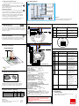
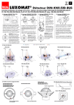
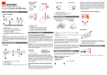
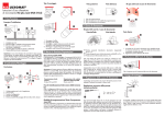
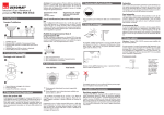
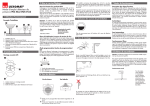
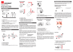
GB LUXOMAT ® PD4-M-TRIO-DALI Installation and Operating Instruction for B.E.G. -Occupancy detectors PD4-Master-TRIO-DALI-SM/-FC 1. Mounting preparations Work on the 230 V mains supply may only be carried out by qualified professionals or by instructed persons under the direction and supervision of qualified skilled electrical personnel in accordance with electrotechnical regulations. 2a. Installation of the LUXOMAT® PD4-M-TRIO-DALI-SM 2b. Installation of the LUXOMAT® PD4-M-TRIO-DALI-FC 100 mm C open close 4. P utting into operation of the remote control (optional) The detector must be installed on a solid and level surface. The circular cover ring must be removed prior to assembly. To do this, twist the lens (C) anticlockwise through approximately 5° and lift off. Having connected up the wires in accordance with regulations, secure the detector with 2 screws. After installation replace the lens and lock (turn clockwise). Mains to be connected. 5. Position of potentiometer and DIP switch 3 A circular opening of diameter 100 mm must be produced in the ceiling. Caution: Settings with remote control supersede the settings by courtesy of potentiometers. FC 1 45 60 30 15 TEST 1 5 1200 600 DIP 321 1 SM 200 2 3 DIP 1 HA / A 40 ON DIP 2 Ini OFF/ON Lamps at start-up OFF/ON OFF DIP 3 RESET Option: Settings by remote control 60 45 30 15 5 to 100 1000 Luminance set point for constant light regulation Dimming of the luminance set point (only for channel 1 and 2) or Saving of the dimmed luminance set point �� 10 ��� to �� 60 ��� Follow-up time light 100 h function Orientation lighting and its follow-up time ON/OFF to 1 min 50 Lux max ON 6 5 4 A 3 B 2 B A 1 2 3 4 5 6 SM 1 FC Light sensor 1 | B Light sensor 2 LED red OFF function LED green too bright/too dark CDS 1 LED white semi-automatic DA 1/2 LED white semi-automatic DA 3 LED green too bright/too dark CDS 2 LED red motion indicator/walking test 1500 Lux 60 min Orientation lighting follow-up time to Orientation lighting 10 – 30% of nominal light or Fully /semi automatic mode (only DA 1/2) => see page 2, point 7 DA 1/2 ON/OFF OFF LED display ON/OFF Locking device – Exit programming mode t < 5 sec. Potentiometer 3: Follow-up time for light control The time can be set infinitely variably at between 1 and 60 minutes. The time-setting is valid for all three channels of the PD4-M-TRIO-DALI. Symbol TEST: Test mode (Every movement switches on the light for a period of 2 second, switching it off for a period of 2 seconds after that regardless of the level of brightness.) Potentiometer 2: Twilight-switch for light control The switch-on value for the light can be set at between 40 and 1200 Lux. Using the rotary control, the luminance set points can be set as desired. Symbol : Night-time operation Symbol : Daytime /Night-time operation Potentiometer 1: Orientation lighting This rotary controller serves to determine the working time of the orientation lighting (fixed to 20 %). “ON” for permanent orientation lighting. “OFF” for deactiviation of orientation lighting. Dimming (=> see page 2, point 8) The following approach will prove useful when setting a command value (example workplace): Place a luxmeter flat on the desk, then, using the remote control IR-PD4-TRIO-DALI, adjust the light up or down by pressing the keys max or min until the desired command value which best suits your requirements has been reached. Sun button – preselected light value (Daylight operation) Wall bracket for remote control IR-PD4-TRIO-DALI 3 2 6 Explanation of the key functions Unlocking device Resetting when open: All values which have been programmed using the remote control are deleted, and those values which have been set by potentiometer are activated. A Self test cycle After an initial 60-second self-test cycle, the LUXOMAT® PD4-M-TRIO-DALI is ready for operation. 2 1. Check Battery: open battery compartment by pressing the plastic springs together and removing the battery-holder. 4 5 1 6. Putting into operation / Settings DIP 123 Remote control LUXOMAT® IR-PD4-TRIO-DALI Position of light sensors and LEDs Having connected up the cables in accordance with regulations, the detector is inserted into the opening as shown and fixed into position with the retaining bracket using screws. Disconnect supply before installing! When in Master/ Slave mode of operation, the Master-appliance must always be installed at the location where there is least daylight. 80 - 90 mm 3. Hardware configuration LED flashes Permanent protection against sabotage Saving of the through 100 h adjusted luminance set point 100 h function to extend the life span – sums up automatically the burning time of 100 % luminosity at the beginning up to 100 hours – only then can lights dim Activate test mode - when locked Deactivate test mode: press Reset Resetting when locked The lighting relay is switched off, i.e. opened and the follow-up times reset. Permanent protection against sabotage when locked This function blocks the unit permanently (all LEDs are flashing). All functions of the remote control are locked. Proceed to exit this mode: reset the hardware using DIP switch 3 or switch the supply voltage as follows: 1sec. 30 sec. - 60 sec. 1sec. ON 230 V OFF DA 1/2 ON/OFF when locked (=> see page 2, point 9) The light will remain switched on/ off for as long as movements are detected in the areas of coverage. Once the last movement has been detected, the light will remain on for the duration of the follow-up time as per setting. The appliance will then return independently to the mode selected (Fully or Semi-automatic). Orientation lighting and its follow-up time ON/OFF Note: During the orientation light phase, the constant light regulation is also active: if there is sufficient brightness, dimming occurs < 2 V and, if applicable, the lighting is switched off. Orientation lighting – Adjustment ot the light intensity The orientation lighting is adjustable in a span from 10 to 30 % of the nominal light. Standard adjustment is 20 %. (see DIP switch functions and IR-PD4-TRIO-DALI on page 1) Automatic operation In this operating mode, the lighting switches automatically on and off for increased comfort, depending on presence and brightness. 13. Wiring diagram Semiautomatic operation In this operating condition, in order to gain increased savings, the lighting is energized only after being manually switched on. Switch-off takes place automatically. The semiautomatic mode basically behaves like the fully automatic one. However, the difference is that switchingon must always be carried out manually! As many (closer-contact) buttons as desired can be wired in parallel on the “S” button input (ON / OFF DIM). (for IR-PD4-TRIO-DALI functions see page 1) You can dim manually by pressing the pushbutton for a long time (> 2 sec.). When the button is released, the current dimming value is retained. Upon renewed dimming, the dimming direction is reversed. 16. DIP switch functions L N DA – DA + T2 T1 DA – DA + DA – DA + 9. Manual Switching R Slave DA3 – DA2 + + S S RNL DA1 –+ optional T1&2 = NO button for semi-automatic mode Slave for enlargement of detection area 14. PD4-M-TRIO-DALI – Connections 8. Manual Dimming DA3 DA 1/2 DIP switch OFF ON 1 (A) Fully automatic channel DA 1/2 + DA3 Semi-automatic channel DA 1/2 + DA3 2 (B) For mains ON / light ON For mains ON / light OFF 3 (C) Standard operation RESET You can switch the lighting on and off manually by pressing the pushbutton for a short time. It will stay on or off as long as people are detected plus the configured follow up time. DIP 1 2 3 ON PD4-M-TRIO-DALI-FC OFF L N 10. Range of Coverage DA – DA + PD4-M-TRIO-DALI DA – DA + 2.50 m T2 T1 R Slave DA – DA + 17. LED function displays LED L L NN S SR Colour Function Display 6 red Motion indicator Lights up for motion detection 5 green Light status indicator DA 1 flashes twice per sec.: - bright enough (light OFF)/ too bright (light ON) flashes once per sec.: - Delay time active 4 white HA/VA DA 1/2 lights when semi-automatic 3 white HA/VA DA 3 lights when semi-automatic 2 green Light status indicator DA 2 flashes twice per sec.: - bright enough (light OFF)/ too bright (light ON) flashes once per sec.: - Delay time active 1 red OFF-function lights when the feature is activated, ie in the initialization phase the light is off all LEDs Acknowledgement flashes once per sec.: - correct input flashes twice per sec.: - incorrect input flashes three times / once per sec.: - Reset when locked flashes three times / twice per sec.: - Double locked all LEDs Status flashes shortly once per sec.: - Detector is double locked DA3 DA 1/2 +– +– –+ DA2 DA1 DA3 2 24 m 1 1 2 360° 6.40 m 8m 12 m 12 m PD4-M-TRIO-DALI-SM 15. Technical data PD4-M-TRIO-DALI quer zum Melder Walking across gehen frontal zumtowards Melder gehen Walking sitzende Tätigkeit Seated 11. Exclude sources of interference e In case the sensing area of the LUXOMAT® PD4-MTRIO-DALI is too large or areas are being covered that should not be monitored, the range can be reduced or limited through use of the enclosed masking clips (e). 12. Article / Part nr. / Accessory Type SM FC FM PD4-M-TRIO-DALI (Master) 92750 92755 – PD4-S (Slave) 92142 92254 92163 LUXOMAT Remote control: IR-PD4-TRIO-DALI (incl. wall bracket) 92104 Accessory: Wire basket BSK Wall bracket for remote control as replacement SM-Socket IP44 for 92730 92199 92100 92386 ® Sensor and power supply in one case Power supply: 230 V~ ±10 % Power consumption: < 1W Ambient temperature: -25°C to +50°C Degree of protection /class: IP20 / II Settings: control dial, DIP switch and remote control Light values-Remote control: 100 - 1000 Lux Extension of the detection area: with Slaves Area of coverage: circular 360° Range of coverage Ø H 2.50 m / T=18°C: seated 6.40 m / tangential 24 m / radial 8 m Recommended height for mounting: 2 - 3 m Light measurement: Mixed light, daylight + artificial light Lux values-Potentiometer: 10 - 1200 Lux • DA 1/2 for light switching, light-controlled • DA 3 for light switching (panel lighting), light-controlled DA 1/2 DALI-BUS regular Max. numbers of connected EB‘s: each 25 for DA1 and DA2, 10 for DA3 Time-settings: 1 - 60 min. / Test Dimensions H x Ø [mm] SM FC PD4-M-TRIO-DALI 124 x 85 100 x 117 Visible portion when built into ceiling: H 37 x Ø 117mm Declaration of Conformity: The product complies with the low voltage recommendation 2006/95/EC and the EMV recommendation 2004/108/EC. We recommend that before dimming of the connected lights a 100 h burn in (T5 tubes or 80 hours for T8 Tubes) function takes place. This can be ignored by using the remote control to deactivate. The lifespan of the lamps can be reduced if the burn in does not take place. 18. Fault-finding Permanently flashing Check whether DIP3 switch (RESET) is set to “ON” Reset to “OFF” if necessary MAN 6621 – 300811–2 7. Fully / Semi automatic mode