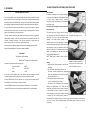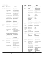
1
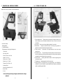
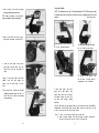
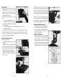
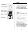
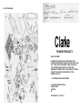
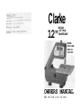
Clarke
WOOD
CUTTING
12"
BANDSAW
MODEL
CBS-12WB
PART NO.
6460008
OWNERS MANUAL
BEFORE USING BE SURE TO REA D THIS MANUAL
CONTENTS
I.
UNPACKINGAND CHECKINGCONTENTS.. . . . . . . . . . . . . . . . . . . . .
2
II.
TO KNOW YOUR BAND SAW . . . . . . . . . . . ' . . . . . . . . . . . . . . . . . . .
Tension AdjustmentKnob
Cover Knobs
Blade Guides
Tension Lock Knob
Guide Bar Lock Knob
Table Lock Knobs
Bevel Scale
On-Off Switch
3
III.
ASSEMBLY. . . . . . . . . . . . . . . . . . . . . .--. . . . . . . . . . . . . . . . . . . . . .
Installingthe Table
4
Replacingthe Blade. . . . . . . . . . . . . . . . . . . . . . . . . . . . . . . . . . . . . . .
Tensioningthe Blade . . . . . . . . . . . . . . . . . . . . . . . . . . . . . . . . . . . . . .
Tracking the Blade. . . . . . . . . . . . . . . . . . . . . . . . . . . . . . . . . . . . . . . .
Adjustingthe Table Square to Blade
5
7
8
AdjustingUpper Blade Guide Assembly.. . . . . . . . . . . . . . . . . . . . . . . .
AdjustingUpper Blade Guides
9
AdjustingUpper Thrust Bearing. . . . . . . . . . . . . . . . . . . . . . . . . . . . . . . 10
AdjustingLower Blade Guide Assembly
MountingBand Saw to Workbench. . . . . . . . . . . . . . . . . . . . . . . . . . . . .
ClampingBand Saw to Workbench. . . . . . . . . . . . . . . . . . . . . . . . . . . . .
IV.
SAFETY RULES . . . . . . . . . . . . . . . . . . . . . . . . . . . . . . . . . . . . . . . .
V.
GROUNDING. . . . . . . . . . . . . . . . . . . . . . . . . . . . . . . . . . . . . . . . . . .
VI.
BASIC OPERATION& TROUBLESHOOTINGGUIDE. . . . . . . . . . . . . . . .
VII.
MAINTENANCE.. . . . . . . . . . . . . . . . . . . . . . . . . . . . . . . . . . . . . . . .
VIII.
TECHNICALD A T A . . . . . . . . . . . . . . . . . . . . . . . . . . . . . . . . . . . . . .
IX
PARTS LISTING . . . . . . . . . . . . . . . . . . . . . . . . . . . . . . . . . . . . . . .
X.
PARTS DIAGRAM. . . . . . . . . . . . . . . . . . . . . . . . . . . . . . . . . . . . . . .
11
12
13
1 6
17
2 0
2 1
2 2
24
I. UNPACKING AND CHECKING CONTENTS
M. TO KNOW YOUR BAND SAW
Unpack carton, check your machine, to see parts listed below:
;
A. Basic saw assembly
B. Owners Manual
C. Saw Table assembly
D. Bag Assembly / Containing the following parts:
1. Switch, Key
1. Tension adjusting knob . . . Tightening the knob (clockwise) will increase the tension on the
blade. Loosening it (counter clockwise) will decrease the tension. (Tension lock knob must
be released).
2. Cover knobs . . . Secure cover to frame by tightening all three (3) cover knobs.
3. Blade Guides . . . Supports the blade and keeps it from twisting during operation. An
adjustment is necessary when blades are changed or replaced.
4. Tension lock knob . . . Holds position of the upper wheel which is set by the tension
adjusting knob.
5. Guide bar lock knob . . . The upper blade guide assembly should just clear the work-piece
while cutting. Always adjust the upper guide assembly and lock the guide bar by tightening
the blade guide lock knob before turning on the band saw.
6. Table lock knobs . . . Loosening knobs allows the table to be tilted and tightening knobs
locks the table in place.
2. Nut, W ing 1/4-20
3. Screw, Truss Hd. 1/4-20 x 3/4
4. Washer 67 x «i16 x tf6
5. W rench, Hex. "L" 3 MM
7. Tilt (bevel) scale . . . Shows degree table is tilted for bevel cutting.
8. ON-OFF SW ITCH. The On-Off Switch has a locking feature. THIS FEATURE IS
INTENDED TO HELP P R E V E N T UNAUTHORIZED AND POSSIBLY HAZARDOUS
USE BY CHILDREN AND OTHERS.
6. W rench, Hex. "L" 5 MM
7. Washer 17/64 x 47/64 x 1/16
8. Indicator, Bevel
9. Screw, Pan Cross #10-24 x 3/8"
10. Insert, Table
11. Knob
Note: If you find any parts missing or damaged, contact the dealer for exchange
replacement.
-2-
-3-
ASSEMBLY
Installing The Table
Replacing
Apply a coat of automobile wax to the table
1. Loosen the guide bar lock knob and position
The Blade
top and inside surfaces of trunnion that
the upper guide assembly approximately one
inch above the table and tighten lock knob.
slide on frame.
1. Loosen the guide bar lock knob and position
the upper guide assembly all of the way up.
Tighten lock knob.
2. Loosen the two blade guard mounting screws
and remove the blade guard.
2. Locate two knobs and two washers in loose
3. Loosen the guide bar lock knob and position
the upper guide assembly approximately two
parts bag, and the table assembly.
inches above the table as shown and tighten
3. Place table assembly onto band saw frame with
the trunnion against mounting rib, in frame.
Hold table assembly against the frame and
install two (2) table lock knobs and washers
as shown through the trunnion slots and
tighten.
4.
Locate bevel indicator and pan cross hd.
screw in loose parts bag.
5.
Install bevel indicator and screw as shown
the lock knob.
4. Remove table insert, truss head screw,
washer and wing nut from the table (See
Assembly, "Adjusting the Table"). Replace
these parts after the blade is installed,
tensioned and tracked.
5.
Loosen the two screws in the front of the
upper blade guide assembly that secure the
blade guides and separate them about 1/8".
using a phillips screwdriver.
6. Loosen the two screws in the side of the upper
guide assembly and slide guides and, thrust
bearing all of the way back. Tighten all
screws.
-4-
-5-
7. Loosen the three (3) cover knobs by turning
counterclockwise and remove cover.
NOTE: Replace the bandsaw cover after blade is
properly installed, tensioned and tracked.
Tensioning The Blade
NOTE: Your bandsaw can use only 1/4" (6mm) wide blades, 56-1/8" (1425mm) long. A blade
is included with this saw. Ensure that, the tension lock knob is tightened before turn on the
machine.
Tension adjusting knob
8. Loosen the two screws that secure the lower
blade guides and separate them about 1/8".
Loosen the tension lock knob a little (1/4
of a turn counter-clockwise).
9.
Turn the tension adjusting knob clockwise until blade has proper tension.
Loosen the screw holding the lower blade
guide support and slide support all the way
toward the rear of the saw, and retighten all
screws.
Warning:
suddenly
carefully
length.
Turn the wheel by handT clockwise a few
e
turns and notice if then blade remains in
s
the approximate center i of the tires.
To avoid being scraped should blade
uncoil, wear safety goggles
and
uncoil the blade holding it at arms
10. Place the blad e over the wheels with the teeth
pointing downward toward the table as
shown. Make sure the blade is in the center
of the rubber tires.
o
n
To check blade tension, push thumb
against side of blade between
lower
wheels. Blade should move only slight ly
with moderate pressure. Be careful not to
over tension blade. Retighten
tension
lock knob.
If too much blade tension has been applied, blades may tend to break more easily and blade life
will be shorter. If too little blade tension has been applied, blade may not track easily, may slip
on whe els, or will move too easily when checking tension.
Note: (1) Tension lock knob must be tighten before mo ving blade.
(2) Loosen the tension adjusting knob a little after usage, (to lengthen
but ensure that the tension lock knob is still fix on the band saw).
-6-
-7-
the blade's life
Tracking The Blade
1. Loosen the Tension Lock Knob (1/4 of a turn
counter-clockwise) and turn the tracking
adjustment set screw slightly with the hex
wrench 3mm (Turning the set screw moves the
NOTE: W hen table is tilted to a bevel angle, the
lower blade guide support should be lowered to
clear the table. After bevel cutting and returning
table to zero position, always raise the lower blade
guide up to provide maximum support for the blade.
tension wheel back and forth.)
2. If the blade moves toward the front of the band
saw:
Turn the tracking adjustment screw
clockwise about 1/4 of a turn, as though you
were tightening it. If the blade moves toward the
back of the band saw:
Turn the tracking adjustment screw counter clockwise about 1/4 of a turn as
though you were loosening it.
Turn the screw just enough to cause the blade to run in the approximate center of all tires.
3. After adjusting, tighten tension knob and turn upper wheel by hand clockwise a few turns
and notice if the blade remains in the approximate center of the tires, Re-adjust if
necessary, until blade is tracking properly.
Aligning The Table Square To Blade
1. Loosen table lock knobs.
Place a square on the table in front of the blade
as illustrated.
Tilt table up or down to align table 90 degrees to
blade (0 degree position) and tighten lock knobs.
NOTE: The upper and lower blade guides support
the blade and keep it from twisting during operation.
An adjustment is necessary when blades are
changed, replaced or installed for the first time.
Adjusting Upper Blade Guide Assembly
*
Loosen lower screw on side of upper blade
guide assembly and slide assembly forward
until the front edge of the blade guides are
approximately 1/32" from the GULLET of the
saw blade. Tighten screw.
Adjusting Upper Blade Guides
* Loosen the two screws that lock the upper blade
guides and press the two guides evenly against the
sides "of the blade but do not pinch the blade.
Release the guides and rotate the upper wheel
slightly clockwise moving the blade downward.
Make sure one guide is not further away from
the blade than the other. Tighten both screws.
2. Adjust zero stop set screw using hex wrench
(3MM) until set screw just touches frame.
Check squareness of blade to table. Make readjustments-if necessary. Set bevel indicator to
line up W ith zero.
-8-
-9-
Adjusting Upper Thrust Bearing
1. NOTE: The thrust bearing supports the blade
from the rear and will rotate when the blade
is pushed against it while you are cutting. As
soon as you stop cutting, the bearing
should stop rotating.
NOTE: After all adjustments have been made, turn the wheel by hand (clockwise) a few turns to
check blade travel and clearance. (As diagram shown in paragram "Ten-sioning the blade")
Adjusting The Table
1. Replace the blade guard on the upper assembly
and tighten screws.
2. Locate the table insert and place it in the opening
in the table. Aiiyn slot in the insert with the slot
in the table.
2. To adjust, loosen the upper screw on the side
of the upper blade guide assembly and slide
the bearing forward until it is approximately
1/32" from the back of the blade. Tighten
screw. Rotate upper wheel slightly clockwise
to check clearance. Re-adjust if necessary.
3. Locate a 1/4 - 20 x 3/4" truss head screw, a f l a t
washer, and a 1 / 4 - 2 0 wing nut in loose parts.
Insert screw into hole in table top as illustrated.
4. From the underside of the table, install washer
and wing nut onto the truss head screw and tighten finger tight. This will keep the table flat
and in alignment.
5. Replace the band saw cover.
Mounting Band Saw To Workbench
If band saw is to be used in a permanent location, it
should be fastened securely to a firm supporting
surface such as a workbench.
Adjusting Lower Blade Guide Assembly
*
Loosen the screw (as shown) on the side of the
lower blade guide assembly and slide assembly
forward until bearing is approximately 1/32"
from the back of the blade. Blade guides will
align with this adjustment. Tighten screw.
If mounting to a workbench, holes should be •
drilled through supporting surface of the
workbench using dimensions illustrated.
1. Each leg should be bolted securely using 3/8"
diameter machine screws, lock-washers, and
3/8" hex nuts (not included).
2. Locate and mark the holes where band saw is
to be mounted.
3. Drill (4) — <b 11 diameter holes through
Adjusting Lower Blade Guides
* Loosen the two screws that lock the lower blade
guides and press the two guides evenly against
the sides of the blade but do not pinch the
blade. Release the guides and rotate the
upper wheel slightly clockwise moving the
blade downward. Make sure one guide is not
further away from the blade than the other.
Tighten both screws.
workbench.
4. Place band saw on workbench aligning holes in feet with holes drilled in workbench.
5. Insert all four 3/8" screws and tighten.
NOTE: Front two mounting bolts should be inserted from the bottom with washer
and nut on top.
An alternate method of mounting is to fasten band saw to a mounting board. The board
should be of sufficient size to avoid tipping of saw while in use. Any good grade of plywood
or chipboard with a 3/4" minimum thickness is recommended. (Thinner chipboard can
break.)
-11-10-
IV. SAFETY RULES
*
Follow
instructions
for
mounting
to
workbench, substituting a board 18" x 24"
minimum size and using inch flat head screws,
General Safety Rules:
1. KEEP GUARDS IN PLACE and in working order.
2.
lock washers, and hex nuts (not included).
NOTE: For proper stability, holes must be
counter sunk so screw heads are flush with the
bottom surface of supporting board.
* Securely clamp board to workbench using "C"
clamps.
REMOVE ADJUSTING KEYS AND W RENCHES. Form habit of checking to
see that keys and adjusting wrenches are removed from tool before turning it on.
3. KEEP W ORK AREA CLEAN. Cluttered areas and benches invite accidents.
4. DON'T USE IN DANGEROUS ENVIRONMENT. Don't use power tools in damp
or wet location, or expose them to rain. Keep work area well lighted.
5. KEEP C H ILD R EN AW AY. All visitors should be kept safe distance from work
area.
NOTE: Supporting surface where band saw
is mounted should be examined carefully
6.
after mounting to insure that no movement
during use can result. If any tipping or
walking is noted, secure workbench or
supporting surface before operating band
saw.
Clamping Bandsaw To Workbench
The Band Saw can be clamped directly to a
workbench using two (2) or more "C"
MAKE W ORKSHOP CHILD PROOF with padlocks, master switches, or by
removing starter keys.
7. DON'T FORCE TOOL. It will do the job better and safer at the rate for which it
was designed.
8. USE RIGHT TOOL. Don't force tool or attachment to do a job for which it was
not designed.
9. WEAR PROPER APPAREL. No loose clothing, gloves, neckties, rings, bracelets,
or other jewelry to get caught in moving parts. Non-slip footwear
recommended. W ear protective hair covering to contain long hair.
clamps on base of unit.
10.
is
ALW AYS USE SAFETY GLASSES. Also use face or dust mask if cutting
operation is dusty. Everyday eyeglasses only have impact resistant lenses, they are
NOT safety glasses.
11. SECURE W ORK. Use clamps or a vise to hold work when practical. It's safer than
using your hand and it frees both hands to operate tool.
12. DON'T OVERREACH. Keep proper footing and balance at all times.
13. MAINTAIN TOOLS W ITH CARE. Keep tools sharp and clean for best and safest
performance. Follow instructions for lubricating and changing accessories.
-12-
14.
DISCONNECT TOOLS before servicing; when changing accessories such as
blades.
15.
REDUCE THE RISK. OF UNINTENTIONAL STARTING. Make sure switch is
in off position before plugging in.
-13-
Special Safety Rules For Band Saws
16.
USE RECOMMENDED ACCESSORIES. Consult the owner's manual for
recommended accessories. The use of improper accessories may cause risk of injury
to persons.
1. Place the blade guard to within approximately 1/8" above the material being cut.
2. Always keep hands and fingers away from the saw blade, especially at the end of
a cut.
17. NEVER STAND ON TOOL. Serious injury could occur if the tool is tipped or if
the cutting tool is unintentionally contacted.
18. CHECK DAMAGED PARTS. Before further use of the tool, a guard or other part
that is damaged should be carefully checked to determine that it will operate
properly and perform its intended function-check for alignment of moving parts,
binding of moving parts, breakage of parts, mounting, and any other conditions
that may affect its operation. A guard or other part that is damaged should be
properly repaired or replaced.
19. NEVER LEAVE TOOL RUNNING UNATTENDED. TURN POW ER OFF. Don't
leave tool until it comes to a complete stop.
20. DIRECTION OF FEED. Feed work into a blade or cutter against the direction of
rotation of the blade or cutter only.
3. Use a push stick or piece of scrap wood to do the pushing and guiding when
sawing small pieces which require the fingers to be close to the saw.
4. Stop the machine before removing scrap pieces from the table.
5. Stop the machine if the material is to be backed out of an uncompleted cut.
6. Make all adjustments and set ups with the power off, such as tilting the table,
adjusting the saw blade guards and blade guides.
7. Adjust blade tension, upper and lower blade guides, backing bearing and blade
tracking correctly.
8. The cover housing must be in place and securely fastened when performing any
saw operations.
9. Securely lock all adjustable parts so they cannot loosen while sawing. This will
prevent distraction from the sawing operation.
10. When sawing curves, make relief cuts to allow removal of scrap material. This will
help prevent undue twisting or binding of the saw blade. The relief cuts are
made before starting the curved saw cut.
11. Hold material firmly and feed into the blade at a moderate speed.
12. Be sure to use proper blade size and type according to guide.
13. Do not saw stock that does not have a flat surface, unless a suitable support is
used.
14.
Keep open flame and high temperature tools such as soldering irons and blow
torches away from band saw.
15. Permanently mount your band saw before performing cutting operations.
-14-
-15-
VI. BASIC OPERATION & TROUBLE SHOOTING GUIDE
V. GROUNDING
GROUNDINGINSTRUCTIONS
Basic Operation
A band saw is basically a "curve cutting" machine. It
flow and reduces the risk of electric shock. This tool has a three-wire electric lead that
is also used for straight-line cutting operations such
as cross cutting, ripping, mitering, beveling,
has a earth conductor and earthed plug. The plug must be used with a matching socket
that is properly installed and earthed according to local building codes and ordinances.
compound cutting, and resawing. It is not capable of
doing inside cutting.
Do not modify the three-pin plug, particularly by cutting off the earth pin. Improper
This band saw is designed to cut wood and wood
like products only.
If an electrical problem occurs, earthing provides the path of least resistance for current
earthing can cause electric shock. If the plug will not fit a particular socket, have the
proper outlet installed by a qualified electrician.
The earth conductor within the power cable has either grech insulation or green-andyellow striped insulation. If the cord must be repaired or replaced, ensure that this
conductor is properly connected, if you have any questions of doubts about the
proper earthing of the tool, check with a qualified electrician.
Use only three-wire extension cables that have three-pin earthed plugs and sockets.
Repair of replace damaged or worn power cables immediately.
For general type scroll cutting, follow the pattern
lines by pushing and turning the workpiece at the
RIGHT - Planning ahead by turning
workpiece for cutting a curve.
same time. Do not try to turn the workpiece while
engaged in the blade without pushing it; the
workpiece could bind or twist the blade. A curve cut
is best performed by keeping the pattern line in with
the blade while turning the workpiece before the
radius of the curve is cut. The blade should cut in the
middle of the pattern line (saw kerf) since wood
WARNING
This appliance must be earthed
cutting band saw blades are thin.
NOTE: Blade guard is raised for clarity of picture
only.
IMPORTANT The wires in this mains lead are
coloured in accordance with the following code.
Green and Yellow
Blue
-EARTH
-NEUTRAL
Brown
—L I V E
As the colours of the flexible cord of this appliance may not correspond with the
coloured markings identifying terminals in your plug, proceed as follows:
Connect GREEN AND YELLOW coloured core to plug terminal marked letter 'E'
Earth Symbol or coloured Green or Green and Yellow.
Connect BROW N coloured core to plug terminal marked letter 'L' or coloured Red.
Connect BLUE coloured core to plug terminal marked letter 'N' or coloured Black.
Sawing
1. Adjust the upper guide assembly to just clear the
workpiece.
W RONG - Not planning ahead for
cutting a curve could bind or twist
blade if workpiece is forced.
2. Use both hands while feeding the work into
the blade. Hold the workpiece firmly against the
table. Use gentle pressure. Do not force the work,
but allow the blade to cu t.
3. The smallest diameter circle that can be
cut out is determined by the width of
the blade. A 1/4" wide blade will cut a minimum
diameter of approximately 1-1/2". Relief cuts are
made when an intricate curve (too small a radius for
a 1/4-inch blade) is to be cut. A relief cut is made by
cutting through scrap section of workpiece to curve
in pattern line, then carefully backing blade out.
Several relief cuts should be made for intricate curves, then follow pattern line as sections
are cut off of curve "relieving" blade pressure. NOTE: Blade guard is raised for clarity of
picture only.
-16-
-17-
4. Trouble Shooting Guide
Problem
Excessive Blade
Probable Cause
Solution
1 Material loose in vise
1 Clamp work securely
2 Teeth too course for
Problem
Probable Cause
Bad
Cuts
5 Guide bearings not adjusted
properly.
5 Adjust guide bearings to .002
greater than max. thickness,
including weld, of the saw.
6 Inadequate blade tension
6 Increase blade tension a little
at a time.
7 Blade guides spaced out too
much.
7 Move guides as close to work as
possible.
8 Dull Blade
8 Replace blade
9 Blade guide assembly loose
9 Tighten
2 Check Machinist Handbook
material.
for recommended
3 Incorrect blade tension
blade type.
3 Adjust to where blade just
does not slip on wheel.
Premature
Blade
4 Teeth in contact with work
before saw is started.
4 Place blade in contact with
work after motor is started.
5 Blade rubs on wheel flange.
5 Adjust wheel alignment
6 Misaligned guides
6 Adjust
7 Blade too thick for wheel
7 Use thinner blade
8 Cracking at weld
8 Make longer annealing cycle.
1 Teeth too course
1 Use finer tooth blade
2 Inadequate feed pressure
material.
10 Blade guide bearing
assembly loose
2 Decrease spring tension on
3 Reduce speed, increase feed
Blade is
1 Cut is binding blade
Twisting
2 Too much blade tension
Unusual Wear
1 Blade guides worn
on Side/Back
2 Blade guide bearing
of Blade
pressure (Scale). Increase feed
pressure (Hard Spots).
4 Work hardening of material 4 Increase feed pressure by
(especially stainless steel)
reducing spring tension.
5 Blade installed backwards
I Blade is too coarse
blade. Always clamp work
tightly in vise.
3 Reduce pressure by increasing
spring tension
-18-
1 Replace
2
Tighten
bracket is loose
1 Use finer tooth blade
2 Too heavy feed; too slow
2 Increase feed pressure and/or
feed
speed
3 Vibrating work piece
3 Clamp work securely
4 Gullets loading
4 Use coarse tooth blade or
brush to remove chips.
1 Blade tension too high
1 Reduce tension on blade
6 Increase tension to proper level.
2 Adjust vise to be square with
3 Feed pressure too great
2 Decrease blade tension
1 Tooth too coarse for work
5 Remove blade, twist inside out
1 Replace with finer blade.
2 Work not square
1 Decrease feed pressure
from Blade
Motor Running
Bad Cuts
11 Retract blade according to
operating instructions.
Teeth Ripping
and reinstall blade.
6 Insufficient blade tension
10 Tighten
11 Blade tracks too far away
from wheel flanges
side of saw
3 Hard spots or scale in/on
Solution
side of saw.
Too Hot
2 Drive belt tension too high
2 Reduce tension on drive belt
3 Blade is too coarse for
work (Pipes especially)
3 Use finer blade
4 Blade is too fine for work
(Heavier, soft material)
4 Use coarser blade
5 Gears not aligned properly
6 Gears need lubrication
5 Adjust gears so that worm is in
center of gear
6 Check oil bath
7 Idler wheel needs
lubrication
7 Oil bearing/shaft on idler
wheel
-19-
VII. MAINTENANCE
VIII TECHNICALDATA
Lubricate the following components periodically.
€
1. Ball bearings.
€
€
€
€
2. Bearings of blade guides.
3. Bearing of driven wheel.
Bench type, portable weight wood cutting
band saw.
Motor direct drive, one speed operation.
Table can be titled 0°— 45 ° for bevel cut.
Sawblade included.
Quiet, free maintenance motor.
SPECIFICATIONS:
Speed ________
2250 FPM (50 Hz) ______________________
Capacity
12" THROAT/3mm 10" THROAT/5Omm
___________.
-20-
3.3/4" (96mm) THICK x 12" (305mm) WIDE_____
Table_________
11 1/2" x 11 ½” (292 x 292mm)
Blade Length____
56-1/8" (1425mm)______________________
Blade Pitch
6T/INCH_____________________________
Motor_________
1/5HP 240VQLT/50HZ/1 PHASE_____________
Dimension______
22-7/16" x 12-13/16" x 23-15/64" (570x325x590mm)
N.W.
34.4 Lbs. (15.6 Kgs.)
G.W._________
40.5 Lbs. (18.4 Kgs.)
-21-
IX. PARTS LISTING
Ref. No.
Description
Part No.
Unit
Ref. No.
Description
Part No.
Unit
1
Knob
MB6A-005
4
37
Shaft guide support
MB6A-036
1
2
3
Washer
Clamp-guide rod
* 1 7/64" x 47/64" x 1/16"
MB6-017
7
1
38
Support upper guide
MB6-014E
1
39
Support guide
MB6-010E
1
4
Screw set hex.
* 1/4" x 2 0 U N C - 3/8"
1
5
6
Knob
Adjustment label
MB6A-005
MB6A -035
1
1
40
41
42
Washer
Guard blade
Insert blade
* 13/ 64"x 1 / 2"x3/ 64"
MB6A -020
MB6-028E
1
1
1
7
8
Guide wheel
Shaft-upper wheel
MB6-018-1
MB6-008
1
1
43
Screw pan cross
* No. 10 - 24UNC - 1/2"
2
9
Bearing-ball
* 6000Z
4
10
11
Wheel-idler
Tire
MB6A-028 (0)
MB6-021
1
3
44
45
46
Screw pan cross
Screw flat cross
Screw-truss
* 1/4" - 20U N C - 3/4"
* 1/4" - 20U N C - 1"
* 1/4" - 20U N C - 3/4"
2
3
1
47
Nut wing
* 1/4--20UNC
1
12
Ring retaining
*S10
2
13
14
Washer
Nut hex.
* 25/64" x 56/64" x 1/16"
* 3/8"-24U NF-L
1
1
48
49
50
Washer
Table band saw
Screw locking set
* 1 7/64" x 5/8" x 1/16"
MB6A-011
* 1/4" - 20U N C - 5/8"
1
1
1
15
Blade band saw
MB6A-016
1
16
17
Knob
Model label
MB6A-005
MB6A-034
3
1
51
52
53
Lock washer-internal
Nut
Lock wahser
* No. 10
* 1/4"-20UNC
* 5/16"
2
3
5
18
19
* * *
Cover frame
* * *
MB6A-003
1
54
55
Nut
Indicator bevel
* 5/16-18UNC
MB6-025E
1
1
20
21
22
Screw pan cross
Ring retaining
Bearing ball
* No. 10 - 24UN C - 3/8"
*d5
* 696ZZ
7
1
1
56
Screw pan cross
* N o. 10 - 20U N C - 3/8"
1
57
58
Trunnion
Motor
MB6-009E
(1) MB6A-001M
1
1
23
Shaft upper guide
MB6A-019
1
24
25
Guide
Shaft-wheel
* < * 5 x 14
MB6-016
4
1
59
60
Motor label
Cord mounting plate
MB6A-010
1
1
26
27
28
Key-switch
Switch locking
Screw pan cross
* 8166 K23 or 8166 K21
* N o.1 0 - 2 4 U N C x 1/4"
1
1
6
29
30
Front cover-switch
Frame
MB6A-027
MB6A-001
1
1
61
62
63
64
Cord power
Foot frame
Screw hex.
Wrench hex.
MB6A - 009
MB6A-002
* 5/16"-18UNC-1%"
* 3MM
1
1
4
1
Screw cap hex.
Lock washer
* 1/4" - 20U N C - 3/4"
* 1/4"
4
4
65
66
Wrench hex.
Connector wire
*5M M
31
32
1
1
33
Support lower guide
MB6A-013
1
67
68
Wheel-idler
Wheel-drive
MB6-006E
MB6A-033 (0)
1
1
34
35
Rod guide support
Spacer
MB6-013E
MB6-038
1
2
69
Clamp-cord
* SR6N3-4
2
70
Caution laber
MB6A-037
1
36
Bearing ball
* L - 940ZZ(N BM)
1
-22-
(2) MSC1/5 -OOOA
Standard Hardware item/may be purchased
23- locally. When ordering service parts. Be
sure to mention model number, parts number and ref. number.
X. PARTS DIAGRAM
Clarke
POWER PRODUCTS
DEAR CUSTOMER
CONGRATULATIONS ON THE PURCHASE OF THIS
CLARKE POWER PRODUCT WHICH WE TRUST WILL GIVE
YOU LONG AND TROUBLEFREE SERVICE. SHOULD
YOU EXPERIENCE ANY DIFFICULTY WITH THE
ASSEMBLY OR OPERATION OF THIS PRODUCT, PLEASE
CONTACT OUR SERVICE DEPARTMENT AT THE
ADDRESS BELOW :CUSTOMER SERVICE DEPARTMENT,
CLARKE INTERNATIONAL,
DOWNS ROAD,
LONDON.
E5.
TELEPHONE : 071 254 6421