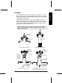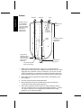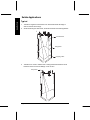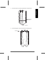
1
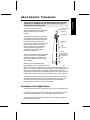
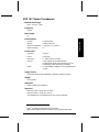
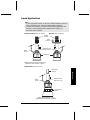
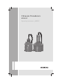
Ultrasonic Transducers XPS10/15F Operating Instructions 08/2013 Safety Guidelines: Warning notices must be observed to ensure personal safety as well as that of others, and to protect the product and the connected equipment. These warning notices are accompanied by a clarification of the level of caution to be observed. Qualified Personnel: This device/system may only be set up and operated in conjunction with this manual. Qualified personnel are only authorized to install and operate this equipment in accordance with established safety practices and standards. Unit Repair and Excluded Liability: The user is responsible for all changes and repairs made to the device by the user or the user’s agent. All new components are to be provided by Siemens Milltronics Process Instruments. Restrict repair to faulty components only. Do not reuse faulty components. Warning: Cardboard shipping package provides limited humidity and moisture protection. This product can only function properly and safely if it is correctly transported, stored, installed, set up, operated, and maintained. This product is intended for use in industrial areas. Operation of this equipment in a residential area may cause interference to several frequency based communications. Note: Always use product in accordance with specifications. Copyright Siemens AG 2013. All Rights Reserved This document is available in bound version and in electronic version. We encourage users to purchase authorized bound manuals, or to view electronic versions as designed and authored by Siemens Milltronics Process Instruments. Siemens Milltronics Process Instruments will not be responsible for the contents of partial or whole reproductions of either bound or electronic versions. Disclaimer of Liability While we have verified the contents of this manual for agreement with the instrumentation described, variations remain possible. Thus we cannot guarantee full agreement. The contents of this manual are regularly reviewed and corrections are included in subsequent editions. We welcome all suggestions for improvement. Technical data subject to change. ® MILLTRONICS is a registered trademark of Siemens Milltronics Process Instruments. Contact SMPI Technical Publications at the following address: Technical Publications Siemens AG Siemens Milltronics Process Instruments 1954 Technology Drive, P.O. Box 4225 Peterborough, Ontario, Canada K9J 7B1 Email: [email protected] European Authorized Representative Siemens AG Industry Sector 76181 Karlsruhe Deutschland For a selection of Siemens Milltronics level measurement manuals, go to: www.siemens.com/processautomation. Under Process Instrumentation, select Level Measurement and then go to the manual archive listed under the product family. For a selection of Siemens Milltronics weighing manuals, go to: www.siemens.com/processautomation. Under Weighing Technology, select Continuous Weighing Systems and then go to the manual archive listed under the product family. © Siemens AG 2013 Table of Contents Table of Contents .................................................................................. i About Siemens’ Transducers.............................................................. 1 Hazardous Area Applications ................................................... 1 Specifications ....................................................................................... 2 XPS 10 F Series Transducers.................................................. 2 XPS 15 F Series Transducers.................................................. 3 Outline and Dimensions ...................................................................... 4 XPS 10 F Series Transducers.................................................. 4 XPS 15 F Series Transducers.................................................. 5 Mounting ............................................................................................... 6 Recommendations ................................................................... 6 Solids Applications (XPS 10 F shown) ..................................... 6 Liquid Applications ................................................................... 7 Interconnection .................................................................................... 8 Interconnection .................................................................................... 9 Recommendations ................................................................... 9 Applications........................................................................................ 11 Liquid Applications ................................................................. 11 Solids Applications ................................................................. 16 Installation Diagram for the XPS 10 F............................................... 20 A5E32725813 XPS 10/15 F Series Transducer Page i Page ii XPS 10/15 F Series Transducer A5E32725813 About Siemens’ Transducers The Echomax XPS F series of transducers operates in association with Siemens ultrasonic level monitoring products. hazardous seal (XPS 10 F series only) transducer The transducer operates by converting electrical pulses that are provided by the transceiver into ultrasonic pulses. When transmitted, these ultrasonic pulses reflect from the material surface and echo back to the transducer. The echo is converted back to an electrical signal, and is interpreted by the Siemens tranceiver using our proven Sonic Intelligence™ algorithms. The effective acoustical energy is emitted from the transducer face and radiated outward, decreasing in amplitude at a rate inversely proportional to the square of the distance. transducer face -3db boundary axis of transmission, perpendicular to transducer face Maximum power is radiated axially (perpendicular) from the transducer face in a line referred to as the axis of transmission. Where power is reduced by half (– 3 dB), a conical boundary defining the sound beam, centered about the axis of transmission, is established. The diametric measurement of the cone in degrees defines the beam angle. Impedance matching techniques are used to optimize the transfer of power from the transducer into air and vice versa. The XPS F series transducers incorporate an integral temperature sensor that reports the air temperature at the transducer to the transceiver. The connection is transparent, in that both the ultrasonic and temperature components of the transducer use the same leads. Hazardous Area Applications The Echomax XPS F series of transducers can be used in hazardous areas. For the XPS 10 F series transducer, a hazardous seal must be used to suit hazardous area classification. This seal is not supplied by Siemens. The XPS 15 F comes equipped with a stainless steel coupling suitable for use in hazardous locations. A5E32725813 XPS 10/15 F Series Transducer Page 1 About the… This product is intended for use in industrial areas. Operation of this equipment in a residential area may cause interference to several frequency based communications. Specifications XPS 10 F Series Transducers Measurement Range: 0.3 – 10m (1 – 33ft) Frequency: 43kHz Specifications Beam Angle: 12° Environmental location: indoor/outdoor altitude: 2000m maximum ambient temperature: -20 to 95°C (-4 to 203°F) pollution degree: 4 Construction exposure: Kynar®1 colour: slate gray mounting: 1” NPT conduit connection options: factory flange to suit ANSI standard submergence shield, where flooding can occur split flange for field mounting to suit ANSI cable: 2-wire shielded / twisted, 0.5 mm2 (20 AWG) PVC jacket Supply Source Transducer shall only be supplied by a Siemens certified controller. Weight2 0.8kg (1.8lb) Separation 365m (1200ft) from transducer Approvals FM Class 1 Div 1, Group A, B, C and D FM Class 2 Div 1, Group E, F, and G see nameplate or consult Siemens for other current approvals 1 2 Kynar® is registered trade mark of ELF Atochem. approximate shipping weight of transducer with standard cable length Page 2 XPS 10/15 F Series Transducer A5E32725813 XPS 15 F Series Transducers Measurement Range: 0.45 – 15m (1.5 – 50ft) Frequency: 43kHz Beam Angle: 6° Environmental location: indoor/outdoor altitude: 2000m maximum ambient temperature: -20 to 95°C (-4 to 203°F) pollution degree: 4 Specifications Construction exposure: Kynar®3 colour: slate gray mounting: 1” NPT conduit connection options: factory flange to suit ANSI standard submergence shield, where flooding can occur split flange for field mounting to suit ANSI cable: 2-wire shielded / twisted, 0.5 mm2 (20 AWG) PVC jacket Supply Source Transducer shall only be supplied by a Siemens certified controller. Weight4 2.0 kg (4.4lb) Separation 365m (1200ft) from transducer Approvals FM Class 1 Div 1, Group A, B, C and D FM Class 2 Div 1, Group E, F, and G see nameplate or consult Siemens for other current approvals 3 4 ® Kynar is registered trade mark of ELF Atochem approximate shipping weight of transducer with standard cable length A5E32725813 XPS 10/15 F Series Transducer Page 3 Outline and Dimensions XPS 10 F Series Transducers Standard Flange (optional) 122mm (4.8”) Outline & Dimensions 122mm (4.8”) 86mm (3.4”) radiating face Split Flange (optional) to suit ANSI standards Submergence Shield (optional) 128mm (5.0”) nominal 152mm (6.0”) to suit ANSI standards 124mm (4.9”) Refer to submergence shield instructions (Siemens’ manual number 7ML19981EG01) Note: For the XPS 10 F series transducer, a hazardous seal must be used to suit hazardous area classification. This seal is not supplied by Siemens. For more information, refer to page 20. Page 4 XPS 10/15 F Series Transducer A5E32725813 XPS 15 F Series Transducers Standard Flange (optional) 1” NPT 304 stainless steel 185mm (7.3”) 120mm (4.7”) Split Flange (optional) 185mm (7.3”) radiating face to suit ANSI standards Submergence Shield (optional) 253mm (10.0”) to suit ANSI standards 158mm (6.2”) Refer to submergence shield instructions (Siemens’ manual number 7ML19981EG01) Note: The XPS 15 F comes equipped with a stainless steel coupling suitable for use in hazardous locations. A5E32725813 XPS 10/15 F Series Transducer Page 5 Outline & Dimensions 191mm (7.5”) nominal Mounting Recommendations Special handling precautions must be taken to protect the face of the transducer from any damage. Mount the transducer so that it is above the maximum material level by at least the blanking value (0.3m for XPS 10 F and 0.45m for XPS 15 F). Refer to the associated transceiver manual for instructions on setting the blanking value. On liquid applications, the transducer must be mounted so that the axis of transmission is perpendicular to the liquid surface. On solids applications, a Siemens Easy Aimer should be used to facilitate aiming of the transducer. Do not over-tighten mounting. Hand tightening of the mounting hardware is sufficient. Secure installation by connecting a safety chain from the transducer to a structural member. Consider the optional temperature sensor when mounting the transducer. Solids Applications (XPS 10 F shown) Mounting Easy Aimer (typical model) safety chain transducer Note: For the XPS 10 F series transducer, a hazardous seal must be used to suit hazardous area classification. This seal is not supplied by Siemens. For more information, refer to page 20. Page 6 XPS 10/15 F Series Transducer A5E32725813 Liquid Applications Notes: In, the examples that follow, an XPS 10 F Series transducer is shown using a hazardous seal. This seal is not supplied by Siemens. An XPS 15 F transducer can also be used in these applications, but, because it comes equipped with a stainless steel coupling, no hazardous seal is required. Flexible Conduit (XPS 10 F shown) Bracket (XPS 10 F shown) flexible conduit steel channel hazardous seal (XPS 10 F only) safety chain transducer Flexible conduit transducer should not be subjected to wind, vibration or jarring. Submersible (XPS 10 F shown) rigid metal conduit Mounting safety chain hazardous seal (XPS 10 F only) submergence shield Submersible transducer, used in applications where flooding is possible. A5E32725813 XPS 10/15 F Series Transducer Page 7 Blind Flange (XPS 10 F shown) nipple welded to bind flange hazardous seal (XPS 10 F only) Flange, gasket, hazardous seal and hardware supplied by customer. Refer to page 13 Flanged (XPS 10 F shown) hazardous seal (XPS 10 F only) Mounting factory flanged transducer bolt gasket customer flanged, flat face only nut Flange, gasket, and hardware supplied by customer. Refer to page 13 Note: Tighten the flange bolts evenly in order to ensure a good seal between the mating flanges. Caution: Over-tightening can cause performance degradation. Page 8 XPS 10/15 F Series Transducer A5E32725813 Interconnection Note: Installation should only be performed by qualified personnel and in accordance with local governing regulations. Recommendations When using an XPS 15 F transducer, configure the electronic transceiver for an XCT-12. These two transducers use the same settings. Do not route cable openly. For optimum isolation against electrical noise, run cable separately in a grounded metal conduit. Seal all thread connections to prevent ingress of moisture. Do not run cable near high voltage or current runs, contactors and SCR control drives. Note: In the interconnection examples that follow: an XPS 10 F Series transducer is shown. An XPS 15 F transducer can also be used, but no hazardous seal is required. assume that the transducer is located in a Hazardous location (Class I, Div. 1, Group A,B,C,D or Class II, Div. 1, Group E,F,G.) and the transceiver in a Non-Hazardous (Safe) Location. Direct Connection (XPS 10 F shown) Hazardous Location (Class I, Div. 1, Group A,B,C,D or Class II, Div. 1, Group E,F,G) Non-Hazardous Location (Safe) metal conduit blk wht drain / shield A5E32725813 XPS 10/15 F Series Transducer Page 9 interconnection Note: When connecting to SITRANS LUT400, SITRANS LUC500, MultiRanger 100/200, or HydroRanger 200, the white, black, and shield wires are all connected separately. DO NOT tie the white and shield wires together. 2-Wire Extension (XPS 10 F shown) Hazardous Location (Class I, Div. 1, Group A,B,C,D or Class II, Div. 1, Group E,F,G) Non-Hazardous Location (Safe) junction box drain / shield metal conduit blk wht extend cable using 18 AWG shielded / twisted pair Note: When connecting to SITRANS LUT400, SITRANS LUC500, MultiRanger 100/200, or HydroRanger 200, the white, black, and shield wires are all connected separately. DO NOT tie the white and shield wires together. Coaxial Cable (XPS 10 F shown) Hazardous Location (Class I, Div. 1, Group A,B,C,D or Class II, Div. 1, Group E,F,G) Non-Hazardous Location (Safe) metal conduit extend cable using RG – 62 A/U coax for optimum noise immunity Interconnection Note: When connecting to SITRANS LUT400, SITRANS LUC500, MultiRanger 100/200, or HydroRanger 200, do NOT use coaxial cable. Page 10 XPS 10/15 F Series Transducer A5E32725813 Applications Liquid Applications Stilling Well / OCM blind flange air vent TS-3 * transducer standpipe bracing standpipe inlet stilling well primary element stilling well inlet Refer to page 13. A5E32725813 XPS 10/15 F Series Transducer Page 11 Applications Notes: The transducer is to be used only in the manner outlined in this instruction manual. Normally, the transducer requires no cleaning or maintenance. However, if performance changes are observed, immediately shut down the level measurement system and perform a thorough inspection, especially on the transducer. An XPS 10 F Series transducer is shown in these examples. An XPS 15 F transducer can also be used, but no hazardous seal is required. Applications * the use of a TS-3 temperature sensor provides better temperature tracking in applications where the temperature can change quickly. Submergence In applications where flooding is possible, the transducer can be fitted with a submergence shield*. The shield acts as a bell to create an air pocket in front of the transducer face. The associated transceiver* interprets this as a flooding condition, and reacts accordingly. Note: Refer to transceiver manual for programming requirements. hazardous seal (XPS 10 F only) transducer submergence shield* (Refer to Siemens instruction manual 7ML19981EG01 for assembly details) air pocket * on applicable models Page 12 XPS 10/15 F Series Transducer A5E32725813 Standpipes The standpipe length should be as short and the diameter as large as possible. As a rule of thumb, the -3 dB cone of the sound beam should not intersect the standpipe wall in applications opening into a vessel or larger area. Otherwise, additional blanking will be required to compensate for the interference zone created by the opening. Note: When using a stilling well, make sure there is no build-up, welds, couplings, or other debris on the inside of the well wall. This can affect reliability of measurement. flanged transducer no vessel no intersection vessel no additional blanking required no additional blanking required nipple welded into blind flange nipple welded into blind flange transducer can read level inside or below standpipe transducer transducer sound beam intersects vessel standpipe end cut on a 45° angle typically no additional blanking required A5E32725813 reflection at interference zone created by opening near blanking extension of 150 mm (6”) past end of standpipe may be required. XPS 10/15 F Series Transducer Page 13 Applications In many applications, access must be made via a standpipe. In such cases, Siemens can provide factory bonded flanged transducers or a split flange kit that will readily mate to the flanged standpipe. Another option is to hang the transducer from a blind flange. Volume Applications ‘Alternate’ ‘Preferred’ ‘Bad’ Maintain full level for full calibration. Above this level erroneous readings will result as level has entered blanking zone. (shaded area) tank manufacturer’s full level beam angle span: corresponds to tank manufacturer’s empty level. rise Empty level for ‘alternate locations. Below this level, echo would reflect away from the transducer. tank manufacturer’s empty level may require target to obtain empty reading discharge 1. Beam should not detect bin bottom. If this occurs, use range extension parameters (on transceivers where available) to omit false echoes. A 6° beam angle (XPS 15 F) represents a rise:run of about 20:1 (10:1 for the 12° beam angle of the XPS 10 F). In most tanks, the transducer should be centered as much as possible (without interference from inlet) for optimum reading range. 2. Sound beam must be perpendicular to liquid surface. If standpipe is used, refer to page 13. 3. Echo has missed improperly levelled transducer. 4. When performing an empty or full calibration, the tank must contain its normal vapour and be at its normal temperature. 5. When used in hazardous areas, the XPS 10 F series transducer (shown) must use a hazardous seal. This seal is not supplied by Siemens. The XPS 15 F Series transducer comes equipped with a stainless steel coupling suitable for use in hazardous locations. Page 14 XPS 10/15 F Series Transducer A5E32725813 Water / Wastewater Applications Differential Level Pump Control Sewage Lift A5E32725813 XPS 10/15 F Series Transducer Page 15 Applications Solids Applications Typical 1. Transducer angled to avoid seams in bin wall and aimed at discharge in order to read bin when empty. 2. Avoid intersecting bin wall seams, structural members and wall irregularities. 1 bin wall seams 2 filling profile emptying profile 3. Transducer too close to material inlet. Falling material will intersect sound beam and cause erroneous readings or loss of echo. Easy Aimer 3 Page 16 XPS 10/15 F Series Transducer A5E32725813 4. On fluid like solids, aim transducer perpendicular to material surface. Applications minimal angle of repose 4 discharge 5. On dual discharge bins, aim each transducer at the discharge point. transducer 5 A5E32725813 XPS 10/15 F Series Transducer Page 17 Applications Special Storage Bin with Agitator 1. Transducer should be kept away from infeed. 2. Where agitators are in use, use the Agitator Discrimination parameter on transceivers where available. 3. Transducer should be aimed away from wall projections. 4. When used in hazardous areas, the XPS 10 F series transducer (shown) must use a hazardous seal. This seal is not supplied by Siemens. The XPS 15 F Series transducer comes equipped with a stainless steel coupling suitable for use in hazardous locations. infeed agitator Page 18 XPS 10/15 F Series Transducer A5E32725813 Dryer - Wood Chips Transducer should be mounted perpendicular to slope of wood chips. 2. When used in hazardous areas, the XPS 10 F series transducer (shown) must use a hazardous seal. This seal is not supplied by Siemens. The XPS 15 F Series transducer comes equipped with a stainless steel coupling suitable for use in hazardous locations. infeed drag conveyor typical low level A5E32725813 XPS 10/15 F Series Transducer typical high level Page 19 Applications 1. Installation Diagram Installation Diagram for the XPS 10 F Page 20 XPS 10/15 F Series Transducer A5E32725813 Notes.fm Page 1 Thursday, October 11, 2001 8:48 AM Notes Notes.fm Page 2 Thursday, October 11, 2001 8:48 AM Notes www.siemens.com/processautomation For more information www.siemens.com/level www.siemens.com/continuous-weighing Siemens AG Industry Sector 1954 Technology Drive P.O. Box 4225 Peterborough, ON Canada K9J 7B1 Subject to change without prior notice A5E32725813 Rev. AA © Siemens AG 2013 email: [email protected] www.siemens.com/processautomation *A5E32725813* Printed in Canada