1
Operator's Manual
12 iN. DUAL BEVEL SLiDiNG
COMPOUND MITER SAW WiTH
LASER TRAC ®
Model No. 137.186290
C
US
CAUTION:
Before using this Miter Saw,
read this manual and follow
all its Safety Rules and
Operating Instructions
Customer
Help Line
For Technical
Support
1-800-843-1682
0
0
Safety Instructions
Installation
0
0
0
Operation
Maintenance
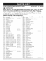
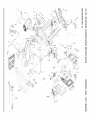
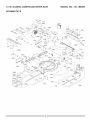
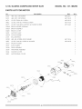
Parts List
Sears Parts &
Repair Center
1-800-488-1222
Sears Brands Management
Corporation
Hoffman
Estates,
See the full line of Craftsman e products at craftsman.corn
Click on the Craftsman Club e link and join today!
Part No. 137186290001
IL 60179
USA
Printed in Taiwan
SECTION
Warranty ...................................................................................................
Product Specifications ..............................................................................
Symbols .....................................................................................................
Power Tool Safety ....................................................................................
Compound Miter Saw Safety ....................................................................
Electrical Requirements and Safety ..........................................................
Accessories and Attachments ...................................................................
Tools Needed for Assembly ......................................................................
Carton Contents ........................................................................................
Know Your Compound Miter Saw .............................................................
Glossary of Terms .....................................................................................
Assembly .................................................................................................
Adjustments ..............................................................................................
Operation ..................................................................................................
Maintenance .............................................................................................
Troubleshooting Guide .............................................................................
Parts List ...................................................................................................
Repair Protection Agreements ..................................................................
CRAFTSMAN
PROFESSIONAL
PAGE
2
3
4
5
7
9
11
12
13
14
15
17
22
28
41
43
45
50
ONE YEAR FULL WARRANTY
FOR ONE YEAR from the date of purchase, this product is warranted against
any defects in material or workmanship. A defective product will receive free
repair or replacement if repair is unavailable.
For warranty coverage details to obtain free repair or replacement, visit the
web site: www.craftsman.com
This warranty does not cover the blade, which is an expendable part that can
wear out from normal use within the warranty period.
This warranty gives you specific legal rights, and you may also have other
rights which vary from state to state.
Sears Brands Management Corporation, Hoffman Estates, IL 60179
,_k WARNING]
Some dust created by power sanding, sawing, grinding, drilling and other
construction
activities contains chemicals known to the state of California
to cause cancer, birth defects or other reproductive harm. Some examples
of these chemicals are:
o Lead from lead-based paints,
o Crystalline silica from bricks and cement and other masonry products, and
o Arsenic and chromium from chemically-treated
lumber.
Your risk from these exposures varies, depending on how often you do this
type of work. To reduce your exposure to these chemical: work in a well
ventilated area, and work with approved safety equipment, such as those
2012/05
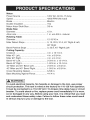
Motor:
Power Source ...........................................
Speed .......................................................
Brake ........................................................
Double insulated .......................................
Motor Arbor Shaft Size ..............................
Blade Size:
Diameter ....................................................
Arbor size .................................................
120V AC, 60 Hz, 15 Amp
4200 RPM (No load)
Electric
Yes
5/8 in.
12 in.
1 in. w/a 5/8 in. reducer
Rotating Table:
Diameter ....................................................
12-15/16 in.
Miter Detent Stops ....................................
0, 15, 22.5, 31.6, 45 ° Right & Left,
60 ° Right
0, 33.9, 45 ° Right & Left
Bevel Positive Stops .................................
Cutting Capacity:
Crosscut ...................................................
Miter 45 ° Left ...........................................
4 in. x 12-1/4 in.
4 in. x 8-3/4 in.
Miter 60 ° Right ...........................................
Bevel 45 ° Left ............................................
4 in. x 6-1/4 in.
2-3/16 in. x 12-1/4 in.
Bevel 45 ° Right ..........................................
45 ° Miter and 45 ° Bevel Left .....................
1-9/16 in. x 12-1/4 in.
2-3/16 in. x 8-3/4 in.
45 ° Miter and 45 ° Bevel Right ................... 1-9/16 in. x 8-3/4 in.
Crown Moulding Nested ............................ 6-5/8 in.
Base Moulding Against Fence ................... 4-1/4 in.
i,i_ WARNING
i
To avoid electrical hazards, fire hazards or damage to the tool, use proper
circuit protection. This tool is wired at the factory for 110-120 Volt operation.
It must be connected to a 110=120 Volt / 15 Ampere time delay fuse or circuit
breaker. To avoid shock or fire, replace power cord immediately if it is worn,
cut or damaged in any way. Before using your tool, it is critical that you read
and understand these safety rules. Failure to follow these rules could result
in serious injury to you or damage to the tool.
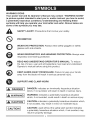
WARNING iCONS
Your power tool and its Operator's
(a picture symbol intended to alert
a potentially hazardous condition).
symbols will help you operate your
some of the symbols you may see.
Manual may contain "WARNING iCONS"
you to, and/or instruct you how to avoid,
Understanding
and heeding these
tool better and safer. Shown below are
SAFETY ALERT: Precautions that involve your safety.
PROHiBiTiON
WEAR EYE PROTECTION:
glasses with side shields.
Always wear safety goggles or safety
WEAR RESPIRATORY AND HEARING PROTECTION:
respiratory and hearing protection.
READ AND UNDERSTAND
OPERATOR'S
Always wear
MANUAL: To reduce
the risk of injury, user and all bystanders must read and understand
Operator's manual before using this product.
KEEP HANDS AWAY FROM BLADE: Failure to keep your hands
away from the blade will result in serious personal injury.
SUPPORT AND CLAMP WORK
[,A
i DANGER: indicates an imminently hazardous situation
DANGER
which, if not avoided, will result in death or serious injury.
i_
1 WARNING: indicates a potentially hazardous situation
WARNING
which, if not avoided, could result in death or serious injury.
CAUTION: indicates a potentially hazardous situation which.
IA CAUTION]
if not avoided, may result in minor or moderate injury.
I CAUTION
i
CAUTION: used without the safety alert symbol indicates
a potentially hazardous situation which, if not avoided, may
result in property damage.
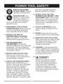
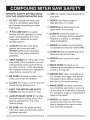
GENERALSAFETYINSTRUCTIONS
BEFOREUSINGTHISPOWERTOOL
Safetyisa combination
ofcommon
sense,stayingalertandknowinghow
to useyourpowertool.
CAUTION
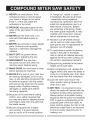
10.USE PROPER EXTENSION
CORDS. Make sure your extension
cord is in good condition. When
using an extension cord, be sure to
use one heavy enough to carry the
current your product will draw. An
undersized cord will result in a drop
in line voltage and in loss of power
which will cause the tool to overheat.
The table on page 10 shows the
correct size to use depending on
cord length and nameplate ampere
rating. If in doubt, use the next
heavier gauge. The smaller the
gauge number, the heavier the cord.
To avoid mistakes that could cause
serious injury, do not plug the tool in
until you have read and understood
the following.
1.
READ and become familiar
with the entire Operator's
Manual. LEARN the tool's
application, limitations and
possible hazards.
2. KEEP GUARDS IN PLACE and in
working order.
11 .WEAR PROPER APPAREL. Do
not wear loose clothing, gloves,
neckties, rings, bracelets or other
jewelry which may get caught in
moving parts. Nonslip footwear is
recommended. Wear protective hair
covering to contain long hair.
3. REMOVE ADJUSTING KEYS
AND WRENCHES. Form the habit
of checking to see that keys and
adjusting wrenches are removed
from the tool before turning ON.
4. KEEP WORK AREA CLEAN.
Cluttered areas and benches invite
accidents.
.
9. USE THE RIGHT TOOL. Do not
force the tool or an attachment to do
a job for which it was not designed.
12. ,SP_L
ALWAYS WEAR EYE
PROTECTION. Any power
tool can throw foreign
objects into the eyes and
could cause permanent eye damage.
ALWAYS wear Safety Goggles
(not glasses) that comply with ANSI
Safety standard Z87.1. Everyday
eyeglasses have only impactresistant lenses. They ARE NOT
safety glasses. Safety Goggles are
available at Sears. NOTE: Glasses
U
DO NOT USE IN DANGEROUS
ENVIRONMENTS. Do not use
power tools in damp locations, or
expose them to rain or snow. Keep
work area well lit.
6. KEEP CHILDREN AWAY. All
visitors and bystanders should be
kept a safe distance from work area.
7. MAKE WORKSHOP CHILD PROOF
with padlocks, master switches or by
removing starter keys.
or goggles not in compliance with
ANSI Z87.1 could seriously injure
you when they break.
8. DO NOT FORCE THE TOOL. It will
do the job better and safer at the
rate for which it was designed.
5
13.
14.
WEAR A FACE MASK
OR DUST MASK. Sawing
operation produces dust.
SECURE WORK. Use
clamps or a vise to hold
work when practical. It
is safer than using your
hand and it frees both hands to
operate the tool.
1&DISCONNECT TOOLS FROM
POWER SOURCE before servicing,
and when changing accessories
such as blades, bits and cutters.
16.REDUCE THE RISK OF
UNINTENTIONAL STARTING.
Make sure switch is in the OFF
position before plugging the tool in.
17.USE RECOMMENDED
ACCESSORIES. Consult this
Operator's Manual for recommended
accessories. The use of improper
accessories may cause risk of injury
to yourself or others.
18.NEVER STAND ON THE TOOL.
Serious injury could occur if the
tool is tipped or if the cutting tool is
unintentionally contacted.
19.CHECK FOR DAMAGED PARTS.
Before further use of the tool, a
guard or other part that is damaged
should be carefully checked to
determine that it will operate
properly and perform its intended
function - check for alignment of
moving parts, binding of moving
parts, breakage of parts, mounting
and any other conditions that may
affect its operation. A guard or other
part that is damaged should be
properly repaired or replaced.
20. NEVER LEAVE THE TOOL
RUNNING UNATTENDED. TURN
THE POWER "OFF". Do not walk
away from a running tool until the
blade comes to a complete stop
and the tool is unplugged from the
power source.
21. DO NOT OVERREACH. Keep
proper footing and balance at all
times.
22. NEVER reach your hand or arm
across the path of the cutting blade.
23. MAINTAIN TOOLS WITH CARE.
Keep tools sharp and clean for best
and safest performance. Follow
instructions for lubricating and
changing accessories.
24. WARNING: Dust generated from
certain materials can be hazardous
to your health. Always operate saw
in well-ventilated area and provide
for proper dust removal.
25.
{_
DANGER
i
People with electronic devices,
such as pacemakers, should
consult their physician(s) before
using this product. Operation
of electrical equipment in close
proximity to a heart pacemaker
could cause interference or failure
of the pacemaker.
SPECiFiCSAFETYiNSTRUCTiONS
10.USE only blade collars specified for
your saw.
FOR THiS COMPOUND MITER SAW
.
.
.
.
.
.
.
.
DO NOT operate the miter saw
until it is completely assembled
and installed according to these
instructions.
11 .NEVER use blades larger in
diameter than 12 inches.
12.NEVER apply lubricants to the
blade when it is running.
iF YOU ARE NOT thoroughly
familiar with the operation of miter
saws, seek guidance from your
supervisor, instructor or other
qualified person.
13.ALWAYS check the blade for
cracks or damage before operation.
Replace a cracked or damaged
blade immediately.
14.NEVER use blades recommended
ALWAYS hold the work firmly
against the fence and table.
DO NOT perform any operation
free hand (use clamp wherever
possible).
for operation at less than 4200 RPM.
15.ALWAYS keep the blade guards in
place and use at all times.
16.NEVER reach around the saw
blade.
KEEP HANDS out of the path of the
saw blade. If the workpiece you are
cutting would cause your hands to
be within 8-3/4 in. of the saw blade,
the workpiece should be clamped in
place before making the cut.
17.MAKE SURE the blade is not
contacting the workpiece before the
switch is turned ON.
1&iMPORTANT: After completing the
cut, release the trigger and wait for
the blade to stop before returning
the saw to the raised position.
BE SURE the blade is sharp, runs
freely and is free of vibration.
ALLOW the motor to come up to full
speed before starting a cut.
1&MAKE SURE the blade has come
to a complete stop before removing
or securing the workpiece, changing
the workpiece angle or changing the
angle of the blade.
KEEP THE MOTOR AiR SLOTS
CLEAN and free of chips or dust.
ALWAYS
MAKE SURE all handles
are tight before cutting, even if the
table is positioned in one of the
positive stops.
20.NEVER cut metals or masonry
products with this tool. This miter
saw is designed for use on wood
and wood-like products.
9. BE SURE both the blade and the
collar are clean and the arbor bolt is
tightened securely.
7
21 .NEVER cut small pieces. If the
workpiece being cut would cause
your hand or fingers to be within
8-3/4 in. of the saw blade the
workpiece is too small.
22.PROVIDE adequate support to the
sides of the saw table for long work
pieces.
23.NEVER use the miter saw in an
area with flammable liquids or
gases.
24.NEVER use solvents to clean plastic
parts. Solvents could possibly
dissolve or otherwise damage the
material.
25.SHUT OFF the power before
servicing or adjusting the tool.
26.DISCONNECT
the saw from
the power source and clean the
machine when finished using.
27.MAKE SURE the work area is clean
before leaving the machine.
28.SHOULD any part of your miter saw
be missing, damaged, or fail in any
way, or any electrical component fail
to perform properly, lock the switch
and remove the plug from the power
supply outlet. Replace missing,
damaged, or failed parts before
resuming operation.
29.Because of the downward cutting
motion, your safety requires that
you stay very alert to keeping hands
and fingers away from the path that
the blade travels.
30.Be sure all guards are in place
and working. If a guard seems
slow to return to its normal position
or "hangs-up", adjust or repair it
immediately. Be alert at all times
- especially during repetitive,
monotonous operations. Don't be
lulled into carelessness due to a
false sense of security. Blades
are extremely unforgiving. Clean
the lower guard frequently to help
visibility and movement. Unplug
before adjustment or cleaning.
31 .Abrasive cut-off wheels should
not be used on miter saws. Miter
saw guards are not appropriate for
abrasive cut-off wheels.
32.To avoid loss of control or placing
hands in the path of the blade,
hold or clamp all material securely
against the fence when cutting. Do
not perform operations freehand.
33.Support long material at the same
height as the saw table.
34.After completing a cut, release the
trigger switch and allow the blade to
come to a complete stop, then raise
the saw blade from the workpiece
35.Lock the miter saw head in the
down position during transport or
when not in use.
36.DRY RUN - It is important to know
where the blade will intersect with the
workpiece during cutting operations.
Always perform a simulated cutting
sequence with the power tool switched
OFF to gain an understanding of the
projected path of the saw blade. At
some extreme angles, the right or left
side fence might have to be removed
to ensure proper clearance prior to
making a cut.
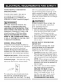
POWERSUPPLYAND
MOTOR
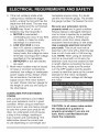
will fit in a polarized outlet only one
way. If the plug does not fit fully in the
outlet, reverse the plug. If it still does
not fit, contact a qualified electrician to
install the proper outlet. Do not change
the plug in any way.
SPECiFiCATiONS
The AC motor used in this saw is
a universal, nonreversible type.
See "MOTOR" in the "PRODUCT
SPECIFICATIONS"
section on page 3.
[,_k WARNING]
[,,d_ WARNING]
Double insulation does not take the
To avoid electrical hazards, fire
hazards, or damage to the tool,
use proper circuit protection. Your
saw is wired at the factory for 120V
operation. Connect to a 120V, 15A
circuit and use a 15A time delay
fuse or circuit breaker. To avoid
place of normal safety precautions
when operating this tool.
To avoid electrocution:
1. Use only identical replacement parts
when servicing a tool with double
insulation. Servicing should be
performed by a qualified technician.
2. Do not use power tools in wet or
damp locations or expose them to
rain or snow.
shock or fire, if power cord is worn
or cut, or damaged in any way, have
it replaced immediately.
MOTOR SAFETY PROTECTION
iMPORTANT
To avoid motor damage, the motor
should be blown out or vacuumed
frequently to keep sawdust from
interfering with the motor ventilation.
1. Connect this saw to a 120V circuit.
This circuit must not be less than a
#12 wire with a 20A time lag fuse or
a #14 wire with a 15A time lag fuse.
NOTE: When using an extension
cord on a circuit with a #14 wire, the
extension cord must not exceed 25
feet in length.
2. If the motor will not start, release
the trigger switch immediately.
UNPLUG THE SAW. Check the
saw blade to make sure it turns
freely. If the blade is free, try to
start the saw again. If the motor
still does not start, refer to the
TROUBLESHOOTING
GUIDE.
DOUBLE iNSULATED []
The power tool is double insulated to
provide a double thickness of insulation
between you and tool's electrical
system. All exposed metal parts are
isolated from the internal metal motor
components with protecting insulation.
Replacement parts - When servicing,
use only identical replacement parts.
Polarized plugs - This saw has a plug
that looks like the one shown below:
To reduce the risk of electrical shock,
this saw has a polarized plug (one
blade is wider than the other). This plug
9
_,
3. If the tool suddenly stalls while
cutting wood, release the trigger
switch, unplug the tool and free the
blade from the wood. The saw may
now be started and the cut finished.
4. FUSES may "blow" or circuit
breakers may trip frequently if:
a. MOTOR is overloaded overloading can occur if you feed
too rapidly or make too many
start/stops in a short time.
b. LINE VOLTAGE is more
than 10% above or below the
nameplate voltage rating. For
heavy loads, the voltage at motor
terminals must equal the voltage
specified on the nameplate.
c. IMPROPER or dull saw blades
are used.
5. Most motor troubles may be traced
to loose or incorrect connections,
overload, low voltage or inadequate
power supply wiring. Always check
the connections, the load and
supply circuit if the motor doesn't
run well. Check minimum gauge for
the length of cord you are using on
the chart below.
nameplate ampere rating. If in doubt,
use the next heavier gauge. The smaller
the gauge number, the heavier the cord.
Be sure your extension cord is
properly wired and in good condition.
Always replace a damaged extension
cord or have it repaired by a qualified
person before using it. Protect your
extension cords from sharp objects,
excessive heat and damp or wet areas.
Use a separate electrical circuit for
your tools. This circuit must not be
less than a #12 wire with a 20A time lag
fuse or a #14 wire with a 15A time lag
fuse. NOTE: When using an extension
cord on a circuit with a #14 wire, the
extension cord must not exceed 25 feet
in length. Before connecting the tool to
the power line, make sure the switch
is in the OFF position and the electric
current is rated the same as the current
stamped on the motor nameplate,
running at a lower voltage will damage
the motor.
(When using 120 volts only)
Ampere
GUIDELINES FOR EXTENSION
CORDS
Use a proper extension cord. Make
sure your extension cord is in good
condition. When using an extension
cord, be sure to use one heavy enough
to carry the current your product will
draw. An undersized cord will cause
a drop in line voltage, resulting in
loss of power and overheating. The
table below shows the correct size
to use depending on cord length and
MoreThan
Rating
Total
Not More Than 25ft.
length
of Cord
50ft.
100ft.
150ft.
0
6
18
16
16
14
6
10
!18
16
14
12
10
j_
[_6 _6
!4
!2
!
CAUTION: In all cases make certain
the receptacle in question is
properly grounded. If you are not
sure, have a certified electrician
check the receptacle.
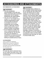
RECOMMENDED
ACCESSORIES
i_
Read warnings and conditions on
your CARBIDE TIPPED SAW BLADE.
WARNING]
e Use only accessories
recommended for this miter saw.
Follow instructions that accompany
accessories. Use of improper
accessories may cause hazards.
o The use of any cutting tool
except 12 in. saw blades which
meet the requirements under
recommended accessories
is prohibited. Do not use
accessories such as shaper
cutters or dado sets. Ferrous
metal cutting and the use of
abrasive wheels is prohibited.
• Do not attempt to modify this
tool or create accessories not
recommended for use with this
tool. Any such alteration or
modification
is misuse and could
result in a hazardous condition
leading to possible
serious
injury.
ACCESSORIES
Visit a Craftsman Hardware
Department or see the Craftsman
Power and Hand Tool Catalog to
purchase recommended
for this power tool.
WAFININGI
accessories
AkWARNINGI
To avoid the risk of personal injury,
do not modify this power tool or use
accessories
that are not Craftsman
recommended.
Do not operate the saw without the
proper saw blade guard in place.
Carbide is a very hard but brittle
material. Care should be taken while
mounting,
using, and storing
carbide
tipped blades to prevent accidental
damage. Slight shocks, such as
striking the tip while handling, can
seriously damage the blade. Foreign
objects in the workpiece, such as
wire or nails, can also cause tips
to crack or break off. Before using,
always visually examine the blade
and tips for bent blade, cracks,
breakage, missing or loose tips, or
other damage. Do not use if damage
is suspected. Failure to heed safety
instructions and warnings can result
in serious bodily injury.
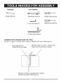
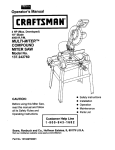
Supplied
Not supplied
Blade Wrench
Adjustable Wrench
Phillips Screwdriver
5 mm Hex Wrench
Slotted Screwdriver
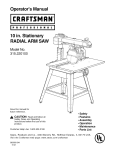
Combination Square
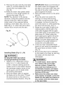
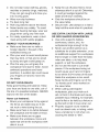
COMBINATION SQUARE MUST BE TRUE
Should not gap or overlap when square is flipped over (see dotted figure).
Draw light line on
board along this edge.
Straight edge or a 3/4 in. board, this
edge must be perfectly straight.
Should not gap or overlap when square
flipped over (see dotted figure).
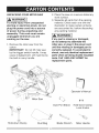
UNPACKING
YOUR
{,A WARNING
MITER SAW
j
To avoid injury from unexpected
starting or electrical shock, do not
plug the power cord into a source
of power during unpacking and
assembly. This cord must remain
unplugged whenever you are
working on the saw.
1. Remove the miter saw from the
carton.
IMPORTANT: Do not lift miter saw
by the trigger switch handle. It may
cause misalignment. Lift machine by
the built-in carry handle.
2. Place the saw on a secure stationary
work surface.
3. Separate all parts from the packing
material. Check each one with the
illustration to make certain all items
are accounted for, before discarding
any packing material.
l_
WARNING
1
If any part is missing or damaged,
do not attempt to assemble the
miter saw, or plug in the power cord
until the missing or damaged part is
correctly replaced. To avoid electric
shock, use only identical replacement
parts when servicing double insulated
tools. Call 1-800=4-MY-HOME e for
replacement
parts.
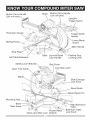
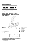
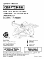
Operator's Manual
Dust Port Elbow
Hold-down Clamp
Dust Bag
Blade Wrench
Hold-down Clamp
Lock Knobs
Miter Handle
Built-inCarryHandle
(Liftunithere)_
Motor Built-inCarryHandle
(Liftunithere)
ON/OFF
TriggerSwitch
Hold-down
Clamp
SlidingFence
TriggerSwitch
Handle
Blade
Guard
4>
MiterHandle
Stop
LeftTableExtension
SafetyLock-offButton
Table Up-frontBevel
LockHandle
PositiveStop
LockingLever
BeltCover
LockStopLatch
LaserTracGuide
Blade........
SlideCarriage
LockKnob
BevelScale
_Bevel
DetentPin
Mounting
Base
TableInse
RightExtension
,;
Table
Table
PositiveMiter --.Extension
LockKnob
Quick-cam
MiterLock Detents
AMPERAGE
(AMPS)- A measure
oftheflowofelectriccurrent.Higher
ratingsgenerallymeansthetoolis
suitedforheavieruse.
ARBORLOCK- Allowstheuserto
keepthebladefromrotatingwhile
tightening
or looseningthearborbolt
duringbladereplacement
or removal.
BASE- Supportsthetable,holds
accessories
andallowsforworkbench
or legsetmounting.
BEVELLOCKINGHANDLE- Locks
themitersawat a desiredbevelangle.
BEVELSCALE- Tomeasurethe
bevelangleofthesawblade0° to45°
leftandright.
CARBIDETIPPED- Extremely
hard
steelpieceswithsharpcuttingedges
fastenedtocuttingtoolssuchassaw
blades.
COVERPLATESCREW- Loosenthis
screwandrotatetheplateforaccessto
thebladearborbolt.
DOUBLE-INSULATED
- Aformof
electricalprotection
featuringtwo
separateinsulationsystemsto help
protectagainstelectricalshock.
EXTENSION
CORD- An electriccord
usedbetweenpowertoolsandoutletsto
extendtherangeofthetools.Themore
amerageyourtooluses,thelongerthe
distance,
thelargerthesizeofthewire
neededinyourextension
cord.
EYE PROTECTION - Googles or
spectacles intended to protect your
eyes. Eye protection should meet the
requirements
ofANSIZ.87.1(USA)or
CSAZ94.3-M88
(Canada).
FACESHIELD- An impactresistant
shieldthathelpstoprotectyourface
fromchips,sparks,smalldebris.
Shouldonlybeusedinconjunction
with
additional
eyeprotection.
FENCE- Helpsto keeptheworkpiece
frommovingwhensawing.Scaledto
assistwithaccuratecutting.
GUARD- Protective
devisethatforms
a barrierbetweena hazardous
object
suchasa blade,wheelor cutterand
theoperator.
LOCKSTOPLATCH- Locksthemiter
sawintheloweredpositionforcompact
storageandtransportation.
INSTRUCTION
OR OPERATOR'S
MANUAL - Booklet accompanying
your power tool that describes the
hazards and safe operation procedures,
outlines basic tool operation, care and
maintenance.
MITER HANDLE - Used to rotate the
table, and to rotate the saw to a right or
left cutting position.
MITER SCALE - Measures the miter
angle of the saw blade. Positive stop
index points have been provided at
0°, 15° , 22.5 °, 31.6 ° and 45 ° right and
left, and 60 ° right.
MOUNTING HOLES - To mount the
miter saw to a stable surface.
ON/OFFTRIGGER
SWITCH- Tostart HEEL- Misalignment
oftheblade.
thetool,squeezethetrigger.Release
KERF- Thewidthofa sawcut,
thetriggertoturnoffthemitersaw.
determined
bythethickness
andsetof
POSITIVE
STOPLOCKING
LEVERtheblade.
Locksthemitersawata presetpositive
KICKBACK- suddenandunintended
stopforthedesiredmiterangle.
movement
ofthetoolorworkpiece.It is
SWITCHHANDLE- Theswitch
typicallycausedby bindingorpinching
handlecontainsthetriggerswitchand oftheworkpiece.
thelaseron/offswitch.Thebladeis
loweredintotheworkpiece
bypushing MITERCUT- A miteris a typeofjoint
wherethetwopartsto bejoinedarecut
downonthehandle.Thesawwill
atanangle,andtypicallythefinished
returnto itsuprightpositionwhenthe
jointformsa
90-degreeangle.Also
handleis released.
commonly
spelled"mitre".
WARNINGLABELS- Readand
PERMINUTE (RPM)
understand
foryourownsafety.Make REVOLUTIONS
The
number
of
turns completed by a
surealllabelsarepresentonmachine
spinning
object
in
one minute.
andlegible.
WRENCH STORAGE - Convenient
SAW BLADE PATH - The area of the
storage to prevent misplacing the blade
wrench.
workpiece or table top directly in line
with the travel of the blade or the part
of the workpiece which will be cut.
WOODWORKING
TERMS
ARBOR - The shaft on which a blade
is mounted.
BEVEL CUT - An angle cut made
through the face of the workpiece.
COMPOUND CUT - An angled cut to
both the edge and face of a board, most
common use is with crown molding.
CROSS CUT - A cut which runs across
the board perpendicular
to the grain.
FREEHAND - Performing a cut without
using a fence (guide), hold down or
other proper device to prevent the
workpiece from twisting during the
cutting operation.
SET - The distance between two saw
blade tips, bent outward in opposite
directions to each other. The further
apart the tips are, the greater the set.
THIN-KERF BLADE - Thinner than
normal blades, remove less material,
smaller kerfs (between .065 in. and
.070 in.). Blade thinness also may
increase the heat generated while
cutting.
WORKPIECE - The wood being cut. The
surfaces of a workpiece are commonly
referred to as faces, ends and edges.
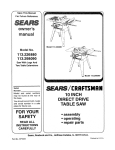
{_
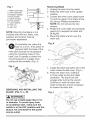
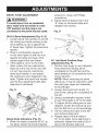
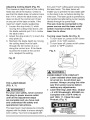
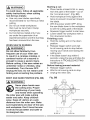
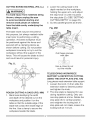
2. Pull out the lock stop latch (2).
3. Allow the cutting head to rise to the
uppermost position.
WARNING]
To avoid injury, do not connect
this miter saw to the power source
until it is completely assembled and
adjusted and you have read and
understood this Operator's Manual.
When transporting
or storing the miter
saw, the cutting head should always be
locked in the down position:
1. Push the cutting head (1) down to
the collapsed position.
2. Push the lock stop latch (2) into the
locking hole (3).
UNLOCKING THE SLIDE CARRIAGE
(FIG. A)
After removing the saw from the carton,
by the two carry handles, loosen the
slide carriage lock knob (1). When
transporting or storing the miter saw,
the slide carriage should always be
locked in position. The slide carriage
lock knob (1) is located on the right
side of the slide carriage.
iMPORTANT: To avoid damage,
never carry the miter saw by the
switch handle, the cutting arm, or the
miter table handle. ALWAYS use the
designated carrying handles located on
the top of the machine.
Fig. B
Fig. A
1
3
2
LOCKING THE CUTTING HEAD (FIG. B)
{_
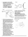
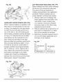
iNSTALLiNG THE MITER HANDLE
(FIG. C)
1. Thread the miter handle (1) into the
hole located at the front of the miter
saw (2).
WARNING]
To avoid injury and damage to the
saw, transport or store the miter saw
with the cutting head in the down
position. NEVER use the lock stop
latch to hold the cutting head in a
down position for cutting operations.
Fig. C
2
To unlock the cutting head from the
collapsed position:
1. Push down slightly on the cutting
head (1).
17
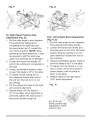
INSTALLING THE DUST BAG (FIG. D)
1. Install the dust port elbow (3) on the
dust port located in the back of the
saw head, behind the motor.
2. Place the dust bag neck opening
around the dust port elbow (3), and
release the metal collar.
Fig. D
Fig. F
2
,_o_,_
o'.iI
_7_
3
....
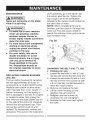
SAW BLADE WRENCH (FIG. G)
For convenient storage and prevention
of loss, there is a clip (1) located at the
rear of the base for storing the blade
wrench (2).
To empty the dust bag (2), squeeze the
metal collar (1) and remove from dust port
elbow. Open the zipper on underside of
the bag and empty into waste container.
NOTE: Check frequently and empty
bag before it gets full.
NOTE: A vacuum hose can be attached
to the saw dust port instead of the dust
bag and elbow.
INSTALLING THE SAFETY HOLDDOWN CLAMP (FIG. E, F)
1. Place the hold-down clamp assembly
(1) into one of the mounting holes (2)
located behind the fence.
2. Thread the hold-down clamp knob
(3) into the hole (2) located at the
rear of the saw base.
3. Tighten the hold-down clamp knob (3).
Fig. E
Fig. G
REMOVING AND INSTALLING THE
TABLE INSERT (FIG. H)
[_
WARNING]
TO AVOID INJURY:
o Always unplug the saw to avoid
accidental starting. Remove all
small pieces of material from
the table cavity underlying the
table insert before performing
any cuts. The table insert may
be removed for this purpose,
but always re=attach the table
insert prior to performing a
cutting operation.
o Do not
start the sliding
compound miter saw without
checking for interference
between the blade and table
insert. Damage could result
to the blade, table insert or
turntable if blade strike occurs
during the cutting operation.
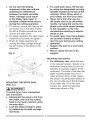
1. To remove, loosen and remove the
six screws (1) on the table inserts
(2) with a Phillips screwdriver and
remove the table insert.
2. To install, reposition the table insert,
install the six screws and tighten.
3. Check for blade clearance by
moving the slide carriage through
the full motion of the blade in the
table slot.
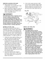
MOUNTING THE MITER SAW
(FIG. H, I)
i_
WARNING]
To avoid injury from unexpected
saw movement:
o Disconnect the power cord from
the outlet, and lock the cutting
head in the lower position using
the stop latch.
o Lock the slide carriage in place
by tightening the slide carriage
lock knob.
o To avoid back injury, lift the saw
by using the designated carrying
handles located on the top of the
machine. When lifting, bend at
your knees, not from your back.
o Never carry the miter saw by
the power cord or by the switch
handle. Carrying the tool by the
power cord could cause damage
to the insulation or the wire
connections
resulting in electric
shock or fire.
o To avoid injury from flying debris,
do not allow visitors to stand
near the saw during any cutting
operation.
o Support the saw on a level work
surface.
o Bolt or clamp the saw to its
support.
Mounting instructions
1. For stationary use, place the saw
in the desired location, directly on a
workbench where there is room for
handling and proper support of the
workpiece. The base of the saw has
eight mounting holes, four 1/4 in.
holes and four 3/8 in. holes. Select
the proper mounting holes based on
the size of bolts used. Bolt the base
of the miter saw (1) to the work
surface (5), using the fastening
method as shown in Fig I.
Fig. I
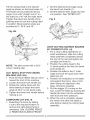
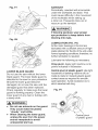
Removing Blade
1. Unplug the saw from the outlet.
2. Raise the miter saw to the upright
position.
3. Loosen the lower cover plate screw
(1) and the upper cover plate screw
(2) using a Phillips screwdriver.
NOTE: Do not remove the two
screws.
4. Rotate the cover plate (3) and blade
guard (4) to expose the arbor bolt
(6-Fig M).
5. Place the blade wrench over the
arbor bolt.
1Mtersaw ase
2. Hex head bolt
3. Rubber washer
_
4. Flat washer
1[
5. Work surface
5 -mL6. Flat washer
|
6
8. Hex nut
9.
7_
7. Jam
Lock nut
washer
,,
i[
: ',
,,
8
NOTE: Mounting hardware is not
included with this tool. Bolts, nuts,
washers and screws must be
purchased separately.
.
For portable use, place the
saw on a 3/4 in. thick piece of
plywood. Bolt the base of the
miter saw securely to the plywood
using the mounting holes on the
base. Use C-clamps to clamp this
mounting board to a stable work
surface at the worksite. (Fig. J)
Fig. J
Fig. K
Locate the arbor lock button (5) on the
motor, below the belt cover. (Fig. L)
8. Press the arbor lock, holding it
in firmly while turning the blade
clockwise. The arbor lock will
engage after turning the wrench.
Continue to hold the arbor lock
while turning the wrench clockwise
to loosen the arbor bolt.
.
REMOVING AND INSTALLING
BLADE (FIG. K, L, M)
WARNING
THE
I
Do not use a blade larger than 12 in.
in diameter. To avoid injury from
an accidental start, make sure the
switch is in the OFF position and the
plug is not connected to the power
source outlet.
Fig. L
5
9. Removethearborbolt(6),theblade
collar(7),andtheblade(8).Donot
removethe innerbladecollar.
(Fig.M)
10.Raise
the lowerclearplasticblade
guard(4)totheuprightpositionto
removetheblade.(Fig.K)
NOTE:Payattentiontothepieces
removed,
notingtheirpositionandthe
directiontheyface.Wipetheblade
collarscleanofanysawdustbefore
installinga newblade.Also,the 12in.
bladehasa 1 in.arborholewitha 5/8in.
reducer(9)tomountontothesaw.
3.
4.
5.
Fig.M
9
6.
7.
Installing Blade (Fig. K, L, M)
i_lk WARNING]
Un=plug the miter saw before
changing/installing the blade.
1. Install a 12 in. blade with a 5/8 in.
arbor (or a 1 in. arbor blade with
a 5/8 in. reducer) making sure the
rotation arrow on the blade matches
the clockwise rotation arrow on the
upper guard, and the blade teeth
are pointing downward.
2. Place the blade collar (7) against
the blade and on the arbor. Thread
the arbor bolt (6) on the arbor in a
counterclockwise direction. (Fig. M)
I
iMPORTANT: Make sure the flats of
the blade collars are engaged with
the flats on the arbor shaft. Also, the
flat-side of the arbor collar must be
placed against the blade.
Place the blade wrench on the arbor
bolt (6).
Press the arbor lock button (5),
holding it in firmly while turning
the blade counterclockwise. When
it engages, continue to press the
arbor lock button in, while tightening
the arbor bolt securely. (Fig. L)
Rotate the cover plate (3) back to its
original position until the slot in the
cover plate engages with the upper
cover plate screw (1) and lower cover
plate screw (2). While holding the
lower blade guard, tighten the screw
with a Phillips screwdriver. (Fig. K)
NOTE: The lower blade guard must
be raised to the upright position to
access the cover plate screw.
Lower the clear retractable blade
guard (4) and verify the operation of
the guard does not bind or stick
(Fig. K).
Be sure the arbor lock is released
so the blade turns freely by spinning
the blade until the arbor lock
disengages.
WARNINGI
o To avoid injury, never use the
saw without the cover plate
secure in place. It keeps the
arbor bolt from falling out if it
accidentally loosens, and helps
prevent the spinning blade from
coming off the saw.
o Make sure the collars are clean
and properly arranged. Lower the
blade into the table and check for
any contact with the metal base
or the saw table.
BEVELSTOP
ADJUSTMENT
{,A WARNING
j
To avoid injury from an accidental
start, make sure the switch is in the
OFF position and the plug is not
connected to the power source outlet.
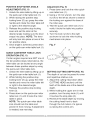
900(0 °) Bevel Adjustment (Fig. N, O)
1. Loosen bevel lock handle (1) and tilt
the cutting arm while pushing in the
bevel detent pin (2) in against the
0 ° bevel stop. Tighten the bevel lock
handle.
2. Place a combination square (3)
on the miter table (4) with the rule
against the table and heel of the
square against the saw blade.
3. If the blade is not 0 ° to the miter
table, loosen the four adjustment
bolts (5) at the rear of the unit with
a 5 mm hex wrench. Unlock the
bevel lock handle (1) and adjust
the cutting arm zero degrees to the
table. Tighten the bevel lock handle
and the four adjustment bolts after
alignment is achieved.
Fig. N
.
screws (1) using a #2 Phillips
screwdriver.
Adjust bevel indicators (2) to the
"0" mark on the bevel scale and
retighten the screws.
Fig. O
45 ° Left Bevel Positive Stop
Adjustment (Fig. P)
1. Set the miter angle to zero degrees.
Fully extend the sliding fence
completely to the left then pull the
bevel detent pin (2) toward the front
of the machine.
NOTE: When retracting the bevel
detent pin, it may be required to shift
the miter saw upper arm assembly
to the left/right.
2. Loosen the bevel lock handle (1)
and tilt the cutting arm completely to
the left.
3. Using a combination square, check
to see if the blade is 45 ° to the table.
Bevel Scale Indicators (Fig. O)
1. When the blade is exactly 900(0 °) to
the table, loosen the bevel indicator
4. To adjust, tilt the cutting arm to zero
degrees, loosen the Iocknut (3) and
turn the bolt (4) in or out accordingly.
5. Tilt the cutting arm back to the left
and recheck alignment.
6. Repeat steps until the blade is
45 ° to the table. Once alignment is
achieved, tighten the Iocknut (3) to
secure the positive stop bolt.
Fig.P
4
Fig. Q
2
3
45° Right
Bevel Positive Stop
Adjustment (Fig. Q)
1. Set the miter angle to zero degrees.
Fully extend the sliding fence
completely to the right then pull
the bevel detent pin (1) toward the
front of the machine. NOTE: When
33.9 ° Left & Right Bevel Adjustment
(Fig. R, S)
1. Set the miter angle to zero degrees.
Fully extend both sliding fences.
2. Loosen the bevel lock handle and
retracting the bevel detent pin, it may
be required to shift the miter saw
upper arm assembly to the left/right.
2. Loosen the bevel lock handle (2)
and tilt the cutting arm completely to
the right.
3. Using a combination square, check
to see if the blade is 45 ° to the table.
3. Using a combination square, check to
see if the blade is 33.9° to the table.
4. To adjust, tilt the cutting arm to
zero degrees, loosen the Iocknut
(3) and turn the bolt (4) in or out
accordingly.
5. Tilt the cutting arm back to the right
and recheck alignment.
6. Repeat steps until the blade is
45 ° to the table. Once alignment is
achieved, tighten the Iocknut (3) to
secure the positive stop bolt.
tilt cutting arm to the 33.9 ° left bevel
positive stop by pushing in on the
bevel detent pin toward the rear of
the machine.
4. To adjust, turn the screw in or out
with a wrench (from the locations
shown below) until the blade is
33.9 ° to the table.
5. Repeat steps for the right bevel
33.9 ° bevel adjustment.
Fig.
R
bevel positive stop
adjustment, insert
wrench here
Fig.S
\
_
,J\
,, •
j,
djq_'_For33.9
_
<..:,__,.,%.':,
_.,7_x,1..
,,,_,
....
_',
',,,7¢'t_,s--.
' -<,',k_>,,
...._']_../,'_,j
_J
......
right
beve pos t ve
sto P adJustment ,
insert wrench
here.
NOTE: View from rear of machine
MITER ANGLE ADJUSTMENT
(FIG. T)
The sliding compound miter saw scale
can be easily read, showing miter
angles from 0 ° to 45 ° to the left, and 0 °
to 60 ° to the right. The miter saw table
has ten of the most common angle
settings with positive stops at 0°, 15 °,
22.5 °, 31.6 °, 45 ° left and right, and
60 to the right. These positive stops
position the blade at the desired angle
quickly and accurately. Follow the
process below for quickest and most
accurate adjustments.
1. Lift up on the quick-cam miter lock
(1) to unlock the table.
2. Move the turntable while lifting up
on the positive stop locking lever
(2) to align the indicator (3) to the
desired degree measurement.
3. Lock the table into position by
pressing down on the quick-cam
miter lock (1).
Fig. T
4
3
MITER SCALE INDICATOR
ADJUSTMENT (FIG. T)
1. Move the table to the 0° positive stop.
2. Loosen the screw (4) that holds the
indicator with a Phillips screwdriver.
3. Adjust the indicator (3) to the 0 °
mark and retighten screw (4).
ADJUSTING FENCE SQUARENESS
(FIG.U)
1. Loosen the four fence locking bolts (1).
2. Lower the cutting arm and lock in
position.
3. Using a square (3), lay the heel of
the square against the blade and the
ruler against the fence (2) as shown.
4. Adjust the fence 90 ° to the blade and
tighten the four fence locking bolts.
CAUTION: if the saw has not
been used recently, recheck
blade squareness to the fence
and readjust if needed.
5. After fence has been aligned, using
a scrap piece of wood, make a cut
at 90 ° then check squareness on
the piece. Readjust if necessary.
Fig. U
POSiTiVE
STOP
ADJUSTMENT
MITER ANGLE
(FIG. V)
1. Unlock the miter table by lifting up on
the quick-cam miter table lock (1).
2. While raising the positive stop
locking lever (2) up, grasp the miter
handle and rotate the miter table left
or right to the desired angle.
3. Release the positive stop locking
lever and set the miter at the
desired angle making sure the lever
snaps into place. NOTE: The lever
will only lock into place at one of the
ten positive stops.
4. Once angle is achieved, press down
on the quick-cam miter table lock (1).
Adjustment (Fig. V)
1. Press down and lock the miter quickcam table lock (1).
2. Using a 13 mm wrench, turn the stop
nut (4) to the left as shown to extend
the locking arm against the base of
the miter saw.
3. Test the quick cam miter lock (1) to
verify it locks the table into position
securely.
4. Turn the lock nut (3) to the right
as shown to lock the miter locking
mechanism into place.
Fig. V
1
3
QUICK-CAM
4
MITER TABLE LOCK
OPERATION (FIG. V)
If miter angles required are NOT one of
the ten positive stops noted above, the
miter table can be locked at any angle
between these positive stops by using
the quick-cam miter table lock.
1. Unlock the miter table by lifting up on
the quick-cam miter table lock (1).
2. While holding the positive stop
locking lever (2) up, grasp the miter
handle and move the miter table left
or right to the desired angle.
3. Release the positive stop locking
lever (2).
4. Press down on the quick-cam miter
table lock (1) until it locks the miter
table in place.
NOTE: The quick-cam miter table
lock should lock the table and
prevent it from moving. If adjustment
is needed, see next step.
2
SETTING CUTTING DEPTH (FIG. W)
The depth of cut can be preset for even
and repetitive shallow cuts.
1. Adjust the cutting head down (See
CUTTING HEAD section) until the
teeth of the blade are at the desired
depth.
2. While holding the upper arm in that
position, turn the stop knob (1) until
it touches the stop plate (2).
3. Recheck the blade depth by moving
the cutting head front to back
through the full motion of a typical
cut along the control arm.
AdjustingCuttingDepth(Fig.W)
Themaximum
depthtravelofthecutting
headwassetatthefactory.Checkto
seethatthebladedoesnotextend more
than 1/4 in. below the table insert, and
does not touch the control arm throat
or any part of the base or table. If the
maximum depth needs readjusting:
1. Loosen the stop knob (1) while
moving the cutting head down until
the blade extends just 1/4 in. below
the table insert.
2. Adjust the stop knob (1) to touch the
stop plate (2).
3. Recheck the blade depth by moving
the cutting head front to back
through the full motion of a cut
along the control arm. If the blade
touches the inside of the control
arm, readjust the setting.
the Laser Trac®cutting guide using Class
Ilia laser beam. The laser beam will
enable you to preview the saw blade path
on the stock to be cut before starting the
miter saw. This laser guide is powered by
the transformed alternating current supply
directly through the power lead.
The saw must be connected to the
power source and the laser on/off
switch must be turned on for the
laser line to show.
Turning Laser Guide On (Fig. X)
1. To turn laser on, press on/off rocker
switch (1) to "ON" position.
2. To turn laser off, press on/off rocker
switch to "OFF" position.
Fig. X
Fig. W
i,_
2
THE LASER BEAM
(FIG. X, Y)
[,,_k WARNING]
For your own safety, never connect
the plug to power source outlet
until all the adjustment steps
are complete and you have read
and understood the safety and
operational instructions.
The laser beam must always be correctly
aligned with the blade to ensure straight,
even cutting. Your tool is equipped with
WARNING
j
AVOID DIRECT EYE CONTACT
o Laser radiated when laser guide
is turned on. Avoid direct eye
contact. Always un-plug the miter
saw from power source before
making any adjustments.
o Laser Warning Label: Max. Output
< 5 mW Wavelength: 630-660 nm,
Complies with 21CFR 1040.10
and 1040. 11. Class Ilia Laser
Product. (Fig. Y)
DIRECT EYE EXPOSURE
=_
_x,0utput<SrnW
LASER RADIATION-AVOID
Wavelength:
63_0nm
Complieswith21CFR1040,10
and104031
....................................
• ...........................................................................
c_ !=_
L_!_od._
Laser Aperture Label: AVOID
EXPOSURE: Laser radiation is
emitted from this aperture. (Fig. Y)
Fig. Z
blade
AVOID EXPOSURE
Laser radiation A
is emittedfrom/_.\
this aperture _V
|
JL
laser be'_am "workpiece /
Fig. Y
Laser Warning Label
_k,,,_,
cutting line
top view
SLIDING THE REAR EXTENSION
Laser Aperture
Label
[_,
WARNING]
To avoid possible personal injury
or damage to the miter saw due to
tipping, do not operate the saw without
the Rear Extension Support Bar.
Loosen the two screws (1) and extend
the rear extension support bar (2) by
sliding it out to match position, tighten
the two screws.
o NOTE: All the adjustments for the
operation of this machine have
been completed at the factory. The
laser guide is calibrated and set up
to project to the left of the blade.
(Fig. Z)
o CAUTION-Use of controls or
adjustments or performance of
procedures other than those
specified herein may result in
hazardous radiation exposure.
o CAUTION=The use of optical
instruments with this product will
increase eye hazard.
o Do not attempt to repair or
disassemble the laser. If
unqualified persons attempt to
repair this laser product, serious
injury may result. Any repair
required on this laser product
should be performed by authorized
service center personnel.
Fig. AA
27
SAFETY iNSTRUCTiONS
SAW OPERATION
FOR BASIC
o Compare the direction of rotation
arrow on the guard to the direction
arrow on the blade. The blade teeth
BEFORE USING THE MITER SAW
i,_k WARNING]
To avoid mistakes that could cause
serious, permanent injury, do not
plug the tool in until the following
steps are completed:
e Completely assemble and
adjust the saw, following the
instructions. (ASSEMBLY AND
ADJUSTMENTS)
o Learn the use and function of the
ON/OFF trigger switch, on/off
switch for laser, upper and lower
blade guards, stop latch, bevel lock
handle, and cover plate screw.
o Review and understand
all safety instructions and
operating procedures in this
Operator's Manual. (SAFETY &
OPERATIONS)
o Review the MAINTENANCE and
TROUBLESHOOTING
GUIDE for
your miter saw.
o To avoid injury or possible death
from electrical shock:
Make sure your fingers do not
touch the plug's metal prongs
when plugging or unplugging
your miter saw. (ELECTRICAL
REQUIREMENTS AND SAFETY)
BEFORE EACH USE iNSPECT YOUR
SAW.
o Disconnect the miter saw.
To avoid injury from accidental
starting, unplug the saw before any
adjustments, including set-up and
blade changes.
o
o
o
o
o
o
o
o
o
should always point downward at
the front of the saw.
Tighten the arbor bolt.
Tighten the cover plate screw.
Check for damaged parts.
Check for:
o Alignment of moving parts
o Damaged electric cords
o Binding of moving parts
o Mounting holes
o Function of arm return spring
and lower guard: Push the
cutting arm all the way down,
then let it rise until it stops.
The lower guard should fully
close. Follow instructions in
TROUBLESHOOTING GUIDE
for adjustment if necessary.
Other conditions that may affect the
way the miter saw works.
Keep all guards in place, in working
order and proper adjustment. If any
part of this miter saw is missing,
bent, damaged or broken in any
way, or any electrical parts don't
work, turn the saw off and unplug it.
Replace bent, damaged, missing or
defective parts before using the saw
again.
Maintain tools with care. Keep the
miter saw clean for best and safest
performance. Follow instructions for
lubricating. Do not put lubricants on
the blade while it is spinning.
Remove adjusting wrench from the
tool before turning it on.
To avoid injury from jams, slips,
or thrown pieces, use only
recommended accessories.
RECOMMENDED
ACCESSORIES
from accidental contact with moving
o ConsulttheACCESSORIES
and
parts, do not do layout, assembly, or
ATTACHMENTS
sectionofthis
setup work on the miter saw while
Operator's
Manualforrecommended any parts are moving.
accessories.
Followtheinstructions
Avoid accidental starting, make sure
thatcomewiththeaccessory.
The
the trigger switch is disengaged
useofimproper
accessories
may
before plugging the miter saw into a
causeriskofinjurytopersons.
power outlet.
o Choosethecorrect12in.diameter PLAN YOUR WORK
bladeforthematerialandthetype
o Use the right tool. Don't force a tool
ofcuttingyouplantodo.
or attachment to do a job it was not
o Makesurethebladeissharp,
designed to do. Use a different tool
undamaged
andproperlyaligned.
for any workpiece that can't be held
Withthesawunplugged,
push
in a solidly braced, fixed position.
thecuttingarmallthewaydown.
Manuallyspinthebladeandcheck CAUTION: This machine is not
forclearance.
Tiltthepower-head
to designed for cutting masonry,
masonry products, ferrous metals
a 45° bevelandrepeatthetest.
(steel, iron, and iron-based metals.)
o Makesurethebladeandarbor
Use this miter saw to cut only
collarsareclean.
o Makesureallclampsandlocksare wood, wood-like products, or nontightandthereis noexcessiveplay ferrous metals. Other material may
shatter, bind the blade, or create
in anyparts.
other dangers. Remove all nails that
KEEPYOURWORKAREACLEAN
Clutteredareasandbenchesinvite
accidents.
i,_ WARNING]
To avoid burns or other fire damage,
never use the miter saw near
flammable liquids, vapors, or gases.
o Plan ahead to protect your eyes,
hands, face and ears.
o Know your miter saw. Read and
understand the Operator's Manual
and labels affixed to the tool. Learn
its application and limitations as well
as the specific potential hazards
peculiar to this tool. To avoid injury
may be in the workpiece to prevent
sparking that could cause a fire.
Remove dust bag when cutting nonferrous metals.
DRESS FOR SAFETY
0
Any power tool can throw
foreign objects into the eyes.
This can result in permanent
eye damage. Everyday
eyeglasses have only impact
resistant lenses and are not
safety glasses. Glasses or
goggles not in compliance with
ANSI Z87.1 could seriously
injure you when they break.
o Donotwearlooseclothing,gloves,
necktiesorjewelry(rings,watches).
Theycangetcaughtanddrawyou
intomovingparts.
o Wearnon-slipfootwear.
o Tiebacklonghair.
o Rolllongsleevesabovetheelbow.
o Noiselevelsvarywidely.Toavoid
possiblehearingdamage,wearear
plugswhenusinganymitersaw.
o Fordustyoperations,
weara dust
maskalongwithsafetygoggles.
INSPECT
YOURWORKPIECE
o Makesuretherearenonailsor
foreignobjectsinthepartofthe
workpiece
beingcut.
o Planyourworktoavoidsmallpieces
thatmaybind,orthataretoosmall
toclampandgeta solidgraspon.
o Planthewayyouwillgraspthe
workpiece
fromstarttofinish.Avoid
awkwardoperations
andhand
positions.Asuddenslipcouldcause
yourfingersor handto moveinto
theblade.
DONOTOVER-REACH
Keepgoodfootingandbalance.Keep
yourfaceandbodytooneside,outof
thelineofa possiblekickback.
NEVER
standinthelineoftheblade.
Never cut freehand:
o Brace your workpiece firmly against
the fence and table stop so it will
not rock or twist during the cut.
o Make sure there is no debris between
the workpiece and the table or fence.
o Make sure there are no gaps
between the workpiece, fence and
table that will let the workpiece shift
after it is cut.
o Keepthecutoffpiecefreetomove
sideways
afteritis cutoff.Otherwise,
itcouldgetwedgedagainstthe
bladeandthrownviolently.
o Onlytheworkpiece
shouldbeon
thesawstable.
o Securework.Useclampsor aviseto
helpholdtheworkwhenit'spractical.
USEEXTRACAUTIONWiTHLARGE
ORODDSHAPEDWORKPIECES
o Useextra supports (tables,
sawhorses, blocks, etc.) for
workpieces large enough to tip.
o Never use another person as a
substitute for a table extension, or as
an additional support for a workpiece
that is longer or wider than the basic
miter saw table, or to help feed,
support, or pull the workpiece.
o Do not use this saw to cut small
pieces. If the workpiece being cut
would cause your hand or fingers
to be within 8-3/4 inches of the saw
blade the workpiece is too small.
Keep hands and fingers out of the
"no hands zone" area marked on
the saws table.
o When cutting odd shaped
workpieces, plan your work so it
will not bind in the blade and cause
possible injury. Molding, for example,
must lie flat or be held by a fixture or
jig that will not let it move when cut.
Properly support round material
such as dowel rods, or tubing, which
have a tendency to roll when cut,
causing the blade to "bite".
,_, WARNING
i
To avoid injury, follow all applicable
safety instructions, when cutting
non=ferrous metals:
o Use only saw blades specifically
recommended for non-ferrous metal
cutting.
o Do not cut metal workpieces
that must be hand held. Clamp
workpieces securely.
o Cut non-ferrous metals only if you
are under the supervision of an
experienced person and the dust bag
has been removed from the saw.
WHEN SAW iS RUNNING
[,_ WARNING]
Do not allow familiarity from
frequent use of your miter saw
to result in a careless mistake. A
careless fraction of a second is
enough to cause a severe injury.
Before cutting, if the saw makes an
unfamiliar noise or vibrates, stop
immediately. Turn the saw OFF.
Unplug the saw. Do not restart until
finding and correcting the problem.
BODY AND HAND POSiTiON (FIG. BB)
Starting a cut:
o Place hands at least 8-3/4 in. away
from the path of the blade - out of
the "no-hands zone". (Fig. BB)
o Hold workpiece firmly against the
fence to prevent movement toward
the blade.
o With the power switch OFF, bring
the saw blade down to the workpiece
to see the cutting path of the blade.
o Squeeze trigger switch to start saw.
o Lower blade into workpiece with a
firm downward motion.
Finishing a cut:
o Hold the cutting arm in the down
position.
o Release trigger switch and wait
for all moving parts to stop before
moving your hands and raising the
cutting arm.
o If the blade doesn't stop within 6
seconds, unplug the saw and follow the
instructions in TROUBLESHOOTING
GUIDE section.
Before freeing jammed material:
o Release trigger switch.
o Wait for all moving parts to stop.
o Unplug the miter saw.
Fig. BB
i,A_ WARNING]
the cutting area. Proper
Never place of
hands
positioning
your near
body
and hands when operating
the miter saw will make cutting
easier and safer. Keep children
away. Keep all visitors at a safe
distance from the miter saw. Make
sure bystanders are clear of the saw
and workpiece. Don't force the saw.
it will do the job better and safer at
its designed rate.
No-Hand Zone
I
8-3/4 in.
8-3/4 in.
BASIC SAW OPERATIONS
SLiDiNG FENCE (FIG. DD)
[,,A WARNING]
[,_
For your convenience, your saw
has a blade brake. The brake is
The sliding fence must be extended to
not a safety device. Never rely on
it to replace the proper use of the
guard on your saw. if the blade
doesn't stop within approximately 6
seconds, wait for the blade to stop,
unplug the saw and contact Sears or
another
qualified
service dealer.
TURNING THE SAW ON (FIG. CC)
Using your right thumb, press in the
safety lock-off button (1). While holding
the lock-off button in, depress the main
the left when making bevel cuts. The
sliding fences note three bevel angles
where the user must adjust the fences
to match the degree of the bevel cut.
Failure to extend the sliding fence will
not allow enough space for the blade
to pass through which could result
in serious injury. At extreme miter or
bevel angles the saw blade may also
contact the fence.
.
Unlock the fence cam locking lever
(1) by pushing it toward the rear of
the machine.
.
Extend the fence (2) by sliding it out
to match the degree of the bevel
cut. Lock the fence cam locking
On/Off trigger switch (2).
NOTE: To make the ON/OFF switch
childproof, insert a padlock (not
provided), or chain with padlock, through
the hole (3) in the trigger switch, locking
the tool's switch, preventing children
and other unqualified users from turning
the machine on.
The miter saw is equipped with an
automatic blade brake. When the
trigger switch is released, the electric
blade brake will stop the blade within
approximately 6 seconds.
Fig. CC
1
WARNING]
lever by pushing it IN toward the
fence. NOTE: When transporting
the saw, always secure the sliding
fence in the collapsed position
(toward the saw blade).
Fig. DD
1
REMOVING OR iNSTALLiNG
THE
Fig. EE
jf
I,A WARNING
l
DRY RUN =it is important to know
where the blade will intersect with the
workpiece during cutting operations.
Always perform a simulated cutting
sequence with the power tool switched
OFF to gain an understanding of the
projected path of the saw blade. At
some extreme angles, the right or left
side fence might have to be removed
to ensure proper clearance prior to
making the cut.
{A CAUTION
1
The right side and left side sliding
fence must be removed when making
any right or left bevel angle cuts
greater than 33.9 ° in combination
with any right or left miter angle.
This fence must also be removed
whenever a 45 ° bevel angle is desired
with a miter angle greater than 31.6 °.
Removing
1. Unlock the fence cam locking lever
by pushing it out toward the rear of
the machine.
SLiDiNG CARRIAGE SYSTEM
(FIG. FF)
[_,
WARNING]
To reduce the risk of injury, return
carriage to the full rear position after
each crosscut operation.
1. For chop cutting operations on
small workpieces, slide the cutting
head assembly completely toward
the rear of the unit and tighten the
carriage lock knob (1).
2. To cut wide boards up to 12-1/4 in.,
the carriage lock knob must be
loosened to allow the cutting head
to slide freely.
Fig. FF
2. Lift up on the sliding fence to
remove it from the saw.
installing
1. Place the sliding fence onto the
miter saw fence.
2. Align the nut (1) with the slot (3),
slot (2) with bolt (4) in the rear of the
fence.
3. To lock the sliding fence, push the
cam locking lever in toward the front
of the machine.
1
BEFORELEAVING
THE SAW
e Never leave tool running
unattended. Turn power OFF. Wait
for all moving parts to stop.
e Make workshop childproof. Lock the
shop. Disconnect master switches.
Store tool away from children and
other unqualified users.
.
If the miter angle desired is NOT
one of the ten positive stops noted
above, simply lock the table at the
desired angle by pressing down on
the quick-cam miter table lock (2).
Fig. GG
i_, WARNING]
To avoid injury from materials being
thrown, always unplug the saw
to avoid accidental starting, and
remove small pieces of material from
the table cavity. The table insert may
be removed for this purpose, but
always reattach the table insert prior
to performing a cutting operation.
MITER CUT (FIG. GG)
The sliding compound miter saw is
equipped with ten positive miter detents
(1) on the saw base. The locations are
at 0, 15, 22.5, 31.6 and 45 degrees left
and right, and 60 ° right. These locations
represent the most common angles for
cutting operation. To make a miter cut:
1. Unlock the miter table by lifting up on
the miter quick-cam table lock (2).
2. While raising the positive stop
locking lever (3) up, grasp the miter
handle (4) and rotate the miter table
left or right to the desired angle.
3. Release the positive stop locking
lever (3) and set the miter at the
desired angle making sure the lever
snaps into place. NOTE: The lever
will only lock into place at one of the
ten positive stops.
4. Once the desired miter angle is
achieved, press down on the quick
cam miter table lock to secure the
table into position.
I
3
BEVEL CUT (FIG. HH)
[,A, WARNING]
e The sliding fence must be
extended to the left when making
bevel cuts. The sliding fences note
three bevel angles where the user
must adjust the fences to match
the degree of the bevel cut. Failure
to extend the sliding fence will not
allow enough space for the blade
to pass through which could result
in serious injury. At extreme miter
or bevel angles the saw blade may
also contact the fence.
e The right side sliding fence must
be removed when making any
right bevel angle cuts greater
than 35 ° in combination
with any
right hand miter angle. This fence
must also be removed whenever
a 45 ° bevel angle is desired with a
miter angle greater than 22.5 ° .
Tiltthecuttingheadtothedesired
angleasshownonthebevelscale(1).
Thebladecanbepositionedatany
angle,froma 90° straightcut(0° on
thescale)to a 45° leftandrightbevel.
Tightenthebevellockhandle(2)by
pushingdowntolockthecuttinghead
inposition.Bevelpositivestopsare
providedat 0°, 33.9° and45°.
2. Setthedesiredbevelangleusing
thebevellockhandle(1).
3. Setthedesiredmiterangleandlock
intoposition.See"MITERCUT".
Fig.I!
Fig.HH
CHOPCUTTING
NARROWBOARDS
90°CROSSCUT
(FIG.JJ)
1. Fora chopcuttingoperations
on
smallworkpieces,
slidethecutting
headassemblycompletely
toward
therearoftheunitandtightenthe
carriagelockknob(1).
2. Positionthecuttingheadtothe
NOTE:Thesawcomeswitha 33.9°
0°bevelpositionandlockthebevel
crownmoldingstop.
lockhandle(2).
3. Positionthetabletothe0° miter
33.9° BEVELSTOPFORCROWN
angleandlockthequickcammiter
MOLDING
(FIG.HH)
tablelock(3).
1. Pushthebeveldetentstoppin(3)in 4. Positiontheworkpiece
onthetable
towardthefrontofthemachine.
andagainstthefence.Usea hold
2. Loosenthebevellockhandle(2).
downclamp(4)attachedtothe
3. Rotatethecuttingheaduntilthe
base,whenever
possible.
beveldetentpinstopsthebevel
5. Pullthetrigger(5),turningonthe
angleat33.9° onthebevelscale.
saw.Lowerthebladebypushingthe
4. Tightenthebevellockhandlebefore
handle(6)downintotheworkpiece
makinga cut.
withslowandeven pressure.
COMPOUND
CUT(FIG.II)
1. Extending
thefencebysliding
itouttotherequiredlocationor
removethe rightslidingfenceif
necessary.
See"SLIDINGFENCE
or REMOVING
SLIDINGFENCE".
6. When the cut is complete, release
the switch and allow the blade to
stop before raising the cutting head
assembly.
Fig. JJ
SLIDE CUTTING WiDE BOARDS UP
TO 12=1/4 iN. WiDE (FIG. KK)
i_
WARNING]
To avoid injury:
o Never pull the cutting head
assembly and spinning blade
toward you during the cut. The
blade may try to climb up on the
top of the workpiece, causing the
cutting assembly and spinning
blade to kick back, forcefully. The
cutting head assembly should
be drawn back completely then
pushed forward when sawing.
o Let the blade reach full speed
before cutting. This will help
reduce the risk of a thrown
workpiece.
o Extending the fence by sliding
it out to the required location or
remove the right sliding fence if
necessary. See "SLiDiNG FENCE
or REMOVING SLiDiNG FENCE".
To Slide Cut Wide Boards (Fig. KK)
1. Unlock the carriage lock knob (1)
and allow the cutting head assembly
to move freely.
2. Set both the desired bevel angle
and/or the miter angle and lock into
position.
3. If bevel cutting, set both the left
and right sliding fences (2) to their
proper location.
4. Use a hold down clamp to secure
the workpiece.
5. Grasp the switch handle (3) and pull
the carrying handle (4) forward until
the center of the saw blade is over
the front of the workpiece (5).
6. Using your right thumb, press
in the safety lock-off button (6).
While holding the lock-off button
in, depress the main On/Off trigger
switch (7).
7. When the saw reaches full speed,
push the saw handle down, slowly,
cutting through the leading edge of
the workpiece.
8. Slowly move the saw handle toward
the fence, completing the cut.
9. Release the trigger and allow
the blade to stop spinning before
allowing the cutting head to raise.
Fig. KK
6
4
CUTTING
ROWED
MATERIAL (FIG. LL)
i_
2. Lower the cutting head to the
depth marked on the workpiece,
holding the upper arm, and adjust
the stop knob (1) until it touches
the stop plate (2). (SEE "SETTING
CUTTING DEPTH" on page 25).
3. Cut two parallel grooves as shown.
WARNING]
To avoid injury from materials being
thrown, always unplug the saw
to avoid accidental starting and
remove small pieces of material
from the table cavity underlying the
table insert.
Fig. MM
The table insert may be removed for
this purpose, but always reattach table
insert prior to performing a cutting
operation. A bowed workpiece must
be positioned against the fence and
secured with a clamping device as
shown before cutting. Do not position
workpiece incorrectly or try to cut the
workpiece without the support of the
fence. This will cause the blade to bind
Cut these grooves
with saw
and could result in personal injury.
Fig. LL
Use a chisel to cut
out the middle
TELESCOPING WORKPIECE
SUPPORT & REPETITIVE CUTTING
USING THE STOP PLATE (FIG. NN)
Long pieces need extension table support.
1. Loosen the knob (1) then slide the
extension table to desired position
and tighten the knob.
2. The stop plate is designed for use
during repetitive cutting. Only use
one stop plate at a time. Rotate the
stop plate (3) to vertical position,
and retighten the locking bolt. If
stop plate will not rotate, loosen the
locking bolt (2) 1/4 turn.
o.
ROUGH CUTTING A DADO (FIG. MM)
1. Mark lines identifying the width
and depth of the desired cut on the
workpiece and position it on the
table so that the outside edge of the
blade will contact the inside edge of
the line. Use a clamp to secure the
workpiece beside the blade.
37
Fig. NN
CUTTING BASE MOLDING (FIG. PP)
Base moldings and many other moldings
can be cut on a compound miter saw.
The setup of the saw depends on
molding characteristics and application,
as shown. Perform practice cuts on
scrap material to achieve best results:
1. Always make sure moldings rest
AUXILIARY
WOOD FENCE (FIG. OO)
When making multiple or repetitive cuts
that result in cut-off pieces of one inch
or less, it is possible for the saw blade
to catch the cut-off piece and throw it
out of the saw or into the blade guard
and housing, possibly causing damage
or injury. To minimize this an auxiliary
wood fence can be mounted to your
saw. Holes are provided in the saw
fence to attach an auxiliary wood fence
(this provides additional depth of cut).
This fence should be constructed of
straight auxiliary wood approximately
3/4 in. thick by 1-1/2 in. high by 22 in.
long. Attach the wood fence securely
and make a full depth cut to make
a blade slot. Check for interference
between the wood fence and the lower
blade guard. Adjust if necessary.
Fig. O0
Slot
firmly against fence and table. Use
hold-down, crown molding vise
or C-clamps, whenever possible,
and place tape on the area being
clamped to avoid marks.
2. Reduce splintering by taping the cut
area prior to making the cut. Mark
the cut line directly on the tape.
3. Splintering typically happens due to
an incorrect blade application and
thinness of the material.
Fig. PP
_
1
_piece
Mit.....
table
J [
Mit .....
table
J
miter at 45 °, bevel at 0 ° miter at 0 °, bevel at 450
CUTTING CROWN MOLDING
(FIG. QQ, RR)
Your compound miter saw is suited
for the difficult task of cutting crown
molding. To fit properly, crown molding
must be compound-mitered with
extreme accuracy. The two surfaces
on a piece of crown molding that fit
flat against the ceiling and wall are at
angles that, when added to_
equal exactly 90 °.
Fig. RR
Settings for standard crown molding
lying flat on compound miter saw table
Inside corner
OR
\
_..x.
Outside corner
Compound cut crown moldings
Most crown molding has a top rear angle
(the section that fits flat against the
ceiling) of 52°and a bottom rear angle (the
section that fits flat against the wall) of 38°.
NOTE: The chart below references
In order to accurately cut crown
molding for a 90 ° inside or outside
corner, lay the molding with its broad
back surface flat on the saw table.
Bevel/Miter Settings
a compound cut for crown molding
ONLY WHEN THE ANGLE BETWEEN
THE WALLS EQUALS 90 °.
KEY SETTING
BEVEL
I
SETTING
MITER I
TYPE OF CUT
n
When setting the bevel and miter angles
inside comer-Left
for compound miters, remember that the
settings are interdependent; changing
one changes the other, as well.
1. Position top of molding
against fence.
2. Miter table set at
31.6 ° Right
RIGHT 31.6 °.
3. LEFT side is
finished piece.
Bevel/Miter
IL
33.9 °
inside corner-Right
Settings
Fig. QQ
IR
33.9 °
31.6 ° Left
iece
OL
33.9 °
Miter saw table
31.6 ° Left
Outside
side
1. Position bottom of
molding against fence.
2. Miter table set at
LEFT 31.6 ° .
3. LEFT side is
finished piece.
Outside
k_
side
comer-Left
side
1. Position bottom of
molding against fence.
2. Miter table set at
LEFT 31.6 ° .
3. RIGHT side is
finished piece.
comer-Right
side
1. Position top of molding
against fence.
OR
33.9 °
31.6 ° Right 2. Miter table set at
RIGHT 31.6 ° .
3. RIGHT side is
finished piece.
CROWN MOLDING CHART
Compound Miter Saw
Miter and Bevel Angle Settings
Wall to Crown Molding Angle
45/45
Crown Molding
Angle
Between
Walls
52/38
Miter
Setting
Crown Molding
Bevel
Setting
Miter
Setting
Bevel
Setting
Angle
Between
Wails
52/38 ° Crown Molding
45/45 ° Crown Molding
Miter
Setting
Bevel
Setting
Miter
Setting
Bevel
Setting
67
42.93
41.08
46.89
36.13
124
18.13
21.71
20.61
19.39
68
69
42.39
41.88
40.79
40.50
46.35
45.81
35.89
35.64
125
126
17.77
17.42
21.34
20.96
20.21
19.81
19.06
18.72
70
41.32
40.20
45.28
35.40
127
17.06
20.59
19.42
18.39
71
40.79
39.90
44.75
35.15
128
16.71
20.21
19.03
18.06
72
40.28
39.61
44.22
34.89
129
16.37
19.83
18.64
17.72
73
39.76
39.30
43.70
34.64
130
16.02
19.48
18.25
17.39
74
39.25
39.00
43.18
35.38
131
18.67
19.07
17.86
17.05
75
38.74
38.69
42.66
34.12
132
15.33
18.69
17.48
16.71
76
38.24
38.39
42.15
33.86
133
14.99
18.31
17.09
16.38
77
37.74
38.08
41.64
33.60
134
14.66
17.93
16.71
16.04
78
37.24
37.76
41.13
33.33
138
14.30
17.85
16.32
18.70
79
36.75
37.45
40.62
33.07
136
13.97
17.17
15.94
18.36
80
81
36.27
35.79
37.13
36.81
40.12
39.62
32.80
32.53
137
138
13.63
13.30
16.79
16.40
15.56
15.19
15.02
14.62
82
35.31
36.49
39.13
32.25
139
12.96
16.02
14.81
14.34
83
84
34.83
34.36
36.17
35.85
38.63
38.14
31.98
31.70
140
141
12.63
12.30
15.64
15.25
14.43
14.06
14.00
13.65
85
33.90
35.52
37.66
31.42
142
11.97
14.87
13.68
13.31
86
33.43
35.19
37.17
31.34
143
11.64
14.48
13.31
12.97
87
32.97
34.86
36.69
30.86
144
11.31
14.09
12.94
12.62
88
32.52
34.53
36.21
30.57
148
10.99
13.71
12.57
12.29
89
32.07
34.20
35.74
30.29
146
10.66
13.32
12.20
11.93
90
31.62
33.86
35.26
30.00
147
10.34
12.93
11.83
11.59
91
31.17
33.53
34.79
29.71
148
I0.01
12.54
11.46
11.24
92
30.73
33.19
34.33
29.42
149
9.69
12.16
11.09
10.89
93
30.30
32.86
33.86
29.13
180
9.37
11.77
10.73
10.55
94
29.86
32.51
33.40
28.83
181
9.05
11.38
10.36
10.20
95
29.43
32.17
32.94
28.54
152
8.73
10.99
10.00
9.85
96
97
29.00
28.58
31.82
31.48
32.48
32.02
28.24
27.94
153
184
8.41
8.09
10.60
10.21
9.63
9.27
9.50
9.15
98
28.16
31.13
31.58
27.64
185
7.77
9.82
8.91
8.80
99
100
27.74
27.32
30.78
30.43
31.13
30.68
27.34
27.03
156
157
7.46
7.14
9.43
9.04
8.55
8.19
8.45
8.10
101
26.91
30.08
30.24
26.73
158
6.82
8.68
7.83
7.75
102
26.50
29.73
29.80
26.42
189
6.51
8.26
7.47
7.40
103
26.09
29.38
29.36
26.12
160
6.20
7.86
7.11
7.05
104
25.69
29.02
28.92
25.81
161
5.88
7.47
6.75
6.70
105
25.29
28.67
28.48
25.50
162
5.87
7.08
6.39
6.35
106
24.89
28.31
28.05
25.19
163
5.26
6.69
6.03
6.00
107
24.49
27.96
27.62
24.87
164
4.95
6.30
5.68
5.65
108
24.10
27.59
27.19
24.56
168
4.63
5.90
5.32
5.30
109
23.71
27.23
26.77
24.24
166
4.32
5.81
4.96
4.94
110
23.32
26.87
26.34
23.93
167
4.01
5.12
4.61
4.59
111
22.93
26.51
25.92
23.61
168
3.70
4.72
4.25
4.24
112
22.58
26.15
25.50
23.29
169
3.39
4.33
3.90
3.89
113
22.17
25.78
25.08
22.97
170
3.08
3.94
3.84
3.53
114
115
21.79
21.42
25.42
25.05
24.66
24.25
22.66
22.33
171
172
2.77
2.47
3.84
3.15
3.19
2.83
3.10
2.83
116
21.04
24.68
23.84
22.01
173
2.15
2.75
2.48
2.47
117
20.67
24.31
23.43
21.68
174
1.85
2.36
2.12
2.12
118
20.30
23.94
23.02
21.36
175
1.84
1.97
1.77
1.77
119
19.93
23.57
22.61
21.03
176
1.23
1.88
1.41
1.41
120
19.57
23.20
22.21
20.70
177
0.92
1.18
1.06
1.06
121
19.20
22.83
21.80
20.38
178
0.62
0.79
0.71
0.71
122
18.84
22.46
21.40
20.05
179
0.31
0.39
0.38
0.35
123
18.48
22.09
21.00
19.72
MAINTENANCE
i,A WARNING]
Never put lubricants on the blade
while it is spinning.
i,_k WARNING]
e
TO avoid
fire
or toxic
reaction,
naphtha
acetone, lacquer thinner or
similar highly volatile solvents to
clean the miter saw.
e To avoid injury from unexpected
starting or electrical shock,
unplug the power cord before
working on the saw.
e For your safety, this saw is
double insulated. To avoid
electrical shock, fire or injury,
use only parts identical to
those identified in the parts
list. Reassemble exactly as
the original assembly to avoid
electrical shock.
never
use
gasoline,
REPLACING CARBON BRUSHES
(FIG. SS)
The two carton brushes (3) furnished
will last approximately 50 hours of
running time, or 10,000 On/Off cycles.
Replace both carbon brushes when
either has less than 1/4 in. length of
carbon remaining, or if the spring or
wire is damaged or burned. To inspect
or replace brushes, first unplug the
saw. Remove the black plastic cap (1)
on the side of the motor (2). Carefully
remove the spring-loaded cap. Then
pull out the carbon brush (3) and
replace. To reassemble, reverse the
procedure. The ears on the metal end
of the assembly go in the same hole
the carbon part fits into. Tighten the
cap snugly, but do not overtighten.
Repeat for the carbon brush located on
the other side of motor.
NOTE: When reinstalling the same
brushes, put them back in the way they
came out. This will avoid a break-in
period that reduces motor performance
and increases wear.
Fig. SS
CHANGING THE BELT (FIG. TT, UU)
o Unplug your saw.
1. Loosen the two bolts (1) with a 5 mm
hex key and remove the belt cover (2).
2. Loosen the set screw (3) with a 4 mm
hex key and four hex screws (4) with
a 5 mm hex key counterclockwise to
move the motor forward.
3. Remove and replace the belt.
4. Lift the motor housing up and
retighten the set screw (3).
5. Retighten the hex screws (4)
clockwise. Do not overtighten.
6. Replace the belt cover and tighten
the bolts.
Fig.TT
SAWDUST
Periodically,
sawdustwillaccumulate
undertheworktable
andbase.This
couldcausedifficultyinthemovement
oftheworktablewhensettingup
a mitercut.Frequently
blowoutor
vacuumupthesawdust.
3
I,A WARNING
i
If blowing sawdust, wear proper
eye protection to keep debris from
blowing into eyes.
Fig.UU
4
LUBRICATION (FIG. VV)
All the motor bearings in this tool are
lubricated with a sufficient amount of highgrade lubricant for the life of the unit under
normal operating conditions; therefore, no
further lubrication is required.
Lubricate the following as necessary:
Chop pivot: Apply light machine oil to
points indicated in illustration.
LOWERBLADEGUARD
Donotusethesawwithoutthelower
bladeguard.Thelowerbladeguardis
attachedtothesawforyourprotection.
Shouldthelowerguardbecome
damaged,
do notusethesawuntilthe
damagedguardhasbeenreplaced.
Checkregularly
to makesurethelower
guardisworkingproperly.Cleanthe
lowerguardof anydustor buildupwith
a dampcloth.
Central pivot of plastic guard: Use light
household oil (sewing machine oil) on
metal-to-metal or metal-to-plastic guard
contact areas as required for smooth,
quiet operation. Avoid excessive oil, to
which sawdust will cling.
I,_
1
Chop
o Do not use solvents on the guard,
They could make the plastic
"cloudy" and brittle.
pivot
WARNING
o When cleaning the lower guard,
unplug the saw from the power
source receptacle to avoid
unexpected start-up.
Fig. VV
Central pivot
of plastic guard
42
i_
WARNING]
To avoid injury from accidental starting, always turn switch OFF and unplug
the tool before moving, replacing the blade or making adjustments.
TROUBLESHOOTING
PROBLEM
Brake does
GUIDE - MOTOR
PROBLEM CAUSE
1. Motor brushes not sealed
not stop
or lightly sticking.
blade within 6 2. Motor brake overheated
seconds.
from use of defective or
wrong size blade or rapid
ON/OFF cycling.
3. Arbor bolt loose.
4. Brushes cracked,
damaged, etc.
5. Other.
SUGGESTED CORRECTIVE
ACTION
1. Inspect/clean/replace brushes.
See MAINTENANCE section.
2. Use a recommended blade. Let
cool down. See REMOVING
OR INSTALLING THE BLADE
section.
3. Retighten. See REMOVING
OR INSTALLING THE BLADE
section.
4. Replace brushes.
5. Contact Sears Service Center.
Motor does
not start
1. Limit switch failure
2. Brush worn.
3. Fuse blown or circuit
breaker tripped on home
panel.
1. Replace limit switch.
2. Replace brushes. See
MAINTENANCE section.
3. Verify there is electrical power at
the outlet.
Brush
1. Brush worn.
2. Other.
1. Replace Brushes. See
MAINTENANCE section.
2. Contact Sears Service Center.
sparked
when switch
released.
TROUBLESHOOTING
PROBLEM
GUIDE - SAW OPERATION
Blade hits table. 1. Misalignment.
Angle of cut not 1. Miter table unlocked.
accurate. Can
2. Sawdust under table.
not adjust miter.
Cutting arm
wobbles.
SUGGESTED CORRECTIVE
ACTION
PROBLEM CAUSE
1. Loose pivot points.
.
See ADJUSTMENT - Setting
Cutting Depth section.
1. See OPERATION - Miter Angle
Adjustment section.
. Vacuum or blow out dust. WEAR
EYE PROTECTION.
1. Contact Sears Service Center.
Cutting arm will 1. Pivot spring not replaced 1. Contact Sears Service Center.
2. Clean and lubricate moving
not fully raise, or
properly after service.
blade guard
2. Sawdust build-up.
parts.
won't fully close.
Blade binds,
ams, burns
wood.
1.
2.
3.
4
Improper operation.
Dull or warped blade.
Improper blade size.
Wood is moving during
cut.
1. See BASIC SAW OPERATION
section.
2. Replace or sharpen blade.
3. Replace with 12 in. diameter
blade.
4. Use hold down clamp to secure
workpiece to table.
Saw vibrates or 1. Saw blade not round /
shakes.
damaged / loose.
2. Arbor bolt loose.
1. Replace blade.
2. Tighten arbor bolt.
12 iN. SLiDiNG COMPOUND
i_
WARNING
MITER SAW
MODEL NO. 137.186290
i
When servicing use only CRAFTSMAN replacement parts. Use of any other
parts many create a HAZARD or cause product damage. Any attempt to
repair or replace electrical parts on this Miter Saw may create a HAZARD
unless repair is done by a qualified service technician. Repair service is
available at your nearest Sears Service Center.
PARTS LiST FOR SAW SCHEMATIC A
I.D,
0831
1545
07X8
083S
083Y
083Z
0CES
0CEZ
0CHG
0DT4
0DT7
0DTZ
0FHW
0HVD
0HVL
0HVN
Description
SHAFT SLEEVE
HEX. SOC, HD.CAP SCREW
DUST PORT ELBOW
TRIGGER
COMPRESSION SPRING
CORD CLAMP
COMPRESSION SPRING
PLUNGER HANDLE
BUMPER
ROLLING WHEEL
BEARING
ARBOR COLLAR
COLLAR
BALL BEARING
BALL BEARING
BALL BEARING
0J4E
0J4F
0J4U
0JBO
0JB3
0JEE
0JFB
0JMP
0JUA
0JUM
0JZF
0K2B
0K51
0K52
0K5D
0K7X
0K7Z
0KA8
0KA9
0KB7
0KB8
0KD4
0KDU
0KE8
0KHC
0KL1
0KQX
0KTK
0KUW
0S1S
0S2B
0WVK
145V
2680
2681
2752
22A4
23NX
25YQ
25YU
262U
262V
FLAT WASHER
FLAT WASHER
FLAT WASHER
WAVE WASHER
WAVE WASHER
C-RING
SELF-LOCKING RiNG
O-RING
HEX. SOC, HD. CAP BOLT
HEX. SOC, HD. CAP BOLT
HEX. SOC, SETSCREW
HEX, SOC, HD, CAP SCREW
CR. RE, COUNT HD, SCREW
CR. RE, COUNT HD, SCREW
CR. RE, COUNT HD, SCREW
{DR RE TRUSSHD ROUND NECKSCREW
CR RE TRUSSHD ROUND NECKSCREW
CR. RE. PAN HD, TAPPING SCREW
CR. RE. PAN HD, TAPPING SCREW
CR. RE. PAN HD, TAPPING SCREW
CR. RE. PAN HD, TAPPING SCREW
CR. RE. PAN HD, SCREW
CR. RE. PAN HD, SCREW
CR. RE. PAN HD, SCREW
CR, RE. PAN HD, SCREW
CR RE PAN HD ROUND NECKSCREW
NUT
STRAIN RELIEF
TERMINAL
COLLAR
CR, RE. PAN HD, TAPPING SCREW
CLAMP BOLT
HEX WASHER HD BOLT
LOCATOR PiN
HELIX GEAR
TRADEMARK LABEL
LOCKING CABLE TiE
GUARD-CORD
CUTTER SHAFT
DUST BAG
GEAR BOX COVER
ANCHOR PLATE
Size
M5_0,8-20
cp6_13-1
cp8_16-2.5
cp6_18-1.5
M5_0,8-8
M6_1,0-25
M6_1.0-10
M6_1.0-16
M4_0,7-8
M4_0,7-12
M6_1.O-20
M6_1.O-10
M6_1.0,-14
M5_12-25
M3_24-10
M4_18-16
M4_18-20
M6_1,0,-10
M6_1,0-12
M6_1,0-60
M6_1,0-12
M6_1.0 T=6
M6_1,0-25
M8_1,28-16
Q'fy
D.
267Y
267Z
PULLEY
GEAR SHAFT
Description
26H6
26LU
26P7
26UK
26UL
275W
27BC
27D7
27D8
27HE
27J9
27JA
27KY
27PF
27WC
290M
29WW
2B62
2BLV
2BQG
2D92
2QQD
2K96
2MOS
2MAR
2QK4
2QYA
2VGE
2VGF
2W4E
2WFZ
2WKZ
2X6M
3544
3841
33C9
33KF
33KJ
33KM
33NZ
34AC
34AY
34CT
34VX
360K
368J
36A6
36A8
36AU
36CC
36CD
36CE
36YW
36Z0
376Y
V-RIBBED TiMiNG BELT (POLYURETHANE)
WARNING LABEL
SHAFT-PIVOT
GEAR SHAFT ASSEMBLY
CUTTER SHAFT ASSEMBLY
PARALLEL KEY
SAFETY CLAMP ASSEMBLY
COLLAR
FOLLOWER PLATE
TORSION SPRING
SET NUT
SCREW STOP
CLAMP BOLT
COMPRESSION SPRING
COMPRESSION SPRING
CAUTION LABEL
SPRING PiN
HEX, HD, BOLT
M6_1,0-16
PLATE
BLANKET WASHER
CONTROLLER ASSEMBLY
SEGMENT HADELE
WARNING LABEL
LiMiT SWITCH
STICKER
BLADE
PULLEY COVER
MOTOR HANDLE
MOTOR HANDLE
COLLAR
BUTTON SWITCH
SPECIAL BOLT
LABEL
LEAD WiRE ASSEMBLY
LOCK KNOB
SUPPORT SEAT
MOTOR ASSEMBLY
LEAD WiRE ASSEMBLY
POWER CABLE
SWIVEL SUPPORT ASSEMBLY
BEARING BUSHING
LEVER
CLEVIS PIN
COLLAR
ROCK SWITCH ASSEMBLY
CABLE SHIELD
DUST SHIELD
CUTTER SHAFT GUARD
ARM
PLUG-BUTTON
LASER ASSEMBLY
PC-GUARD ASSEMBLY
CAUTION LABEL
LABEL
CR. RE. PAN HD. SCREW
M6"1.0-100
38AW SPRINGGUARD
45
Size
Q'ty
1
1
1
1
1
1
1
1
1
1
1
1
1
1
1
1
1
1
2
1
1
1
1
1
1
1
1
1
1
1
1
1
1
2
1
1
1
1
1
1
1
1
1
1
1
1
1
1
1
1
1
3
1
1
1
1
1
1
::=
rrl
0S£B£
<
262U
co
r-
[
07X8
63
0
2QYA
0
--- --- ...
]
0
C
Z
860K
o
-4
m
Or}
Ob
\SQK4
$8C9
//
23NX
2BQG
/
2W4E
33NZ
/
-./
0
13
rrl
ri/
29VVV_2//\
Z
0
,,,,,,,&
",4
CO
0'_
¢0
0
12 iN. SLiDiNG COMPOUND
MITER SAW
PARTS LiST FOR SAW SCHEMATIC
I.D.
082J
CUSHION
Description
082Q
LOCK NUT
091S
COMPRESSION
0D7Z
Size
MODEL NO. 137.186290
B
Q'ty
2
I.D.
26NN
UPPER TUBE
26NS
LOCKING
27BU
TABLE iNSERT
1
KNOB-HANDLE
27BV
TABLE iNSERT
1
0DTH
CENTER BOLT
27H1
CLAMP-CORD
1
0DVJ
BLADE WRENCH
27KA
ECCENTRIC
0J4D
FLAT WASHER
cp5_10-1
2
27PQ
ROLL PiN
0J4E
FLAT WASHER
cp6_13-1
1
27Y4
HEX. SOC. SETSCREW
M6_1.0-16
2
0J4N
FLAT WASHER
cpl 6"30-3
2
283H
HEX. SOC. HD. CAP SCREW
M5_0.8-12
4
0J4P
FLAT WASHER
cp8"16-1.4
2A J3
CLAMP
0J6A
FLAT WASHER
cp8"16-2.8
2B4P
FENCE PLATE
2
0J78
FLAT WASHER
1/4_1/2-3/32
2B4Q
EXTENTION WiNG
1
0J7K
FLAT WASHER
3/8_29/32 5/64
2B4R
EXTENTION WiNG
1
0J8P
FLAT WASHER
3/8_29/32 5/64
2B4S
SLIDE PLATE
3
0JA6
WASHER
cp5
2
2B4Y
NEEDLE POINTER
1
0JBO
WAVE WASHER
2
2B4Z
NEEDLE POINTER
0JEV
E-RING
1
2BLQ
HEX. SOC. HD. CAP SCREW
0JMN
O-RING
1
2BQA
PLATE
0JPF
HEX. HD. BOLT
M6_1.0-25
2
2C1H
LOCATING
0JUB
HEX. SOC. HD. CAP BOLT
M5_0.8-12
2
2C1J
SPECIAL BOLT
1
0JXG
HEX. SOC. SETSCREW
M8_1.25-16
1
2C7F
UPPER TUBE
2
0K2B
HEX. SOC. HD. CAP SCREW
M6_1.0-16
1
2C91
EXTENTION WiNG
ASSEMBLY
1
0K2N
HEX. SOC. HD. CAP SCREW
M8_1.25-25
4
2C92
EXTENTION WiNG
ASSEMBLY
1
0K55
CR. RE. COUNT
M5_0.8-8
4
2CR5
BRACKET-TILT
0K74
CR. RE. TRUSS HD. SCREW
M6_1.0-8
2
2CR6
BRACKET-TILT
0K7F
CR. RE. ROUND WASHER HD. SCREW M5_0.8-8
1
2D7E
COMPRESSION
0KAE
CR. RE. PAN HD. TAPPING
M5_0.8-10
2
2D9W
LOCKING
0KB9
CR. RE. TRUSS HD. TAPPING
SCREW
M3_24-12
1
2DAN
REAR EXTENTION STAY
1
0KCF
CR. RE. TRUSS HD. TAPPING
SCREW
M4_18-10
6
2ED6
CAUTION
1
0KDG
CR. RE. PAN HD. SCREW
M5_0.8-6
2
2K8Q
WARNING
0KDH
CR. RE. PAN HD. SCREW
M5_0.8-8
1
2QBG
CLAMP
0KDM
CR. RE. PAN HD. SCREW
M5_0.8-20
3
2T6L
PLUNGER HANDLE
1
0KDR
CR. RE. PAN HD. SCREW
M5_0.8-10
2
2VH5
LINEAR MOTION
3
0KDT
CR. RE. PAN HD. SCREW
M6_1.0-8
2
2ZBQ
CR. RE. TRUSS HD. SCREW
0KQW
LOCK NUT
M5_0.8 T=5
3498
BEARING
0KQY
LOCK NUT
M8_1.25
T=8
349B
ASSIST-FENCE(RIGHT)
1
0KQZ
NUT
M10_1.5
T=10
0KR1
LOCK NUT
M16_2.0
T=16
349C
34A8
ASSIST-FENCE(LEFT)
ARM-MITER
1
1
0KR2
LOCK NUT
M5_0.8 T=5
2
34BL
FENCE
10LF
HEX. NUT
M6_1.0 T=4
2
34DK
LOCK NUT
2750
CAUTION
1
34JU
SHAFT-PIVOT
1
2754
WARNING
1
354V
SPECIAL BOLT
2
2840
COMPRESSION
1
35AY
ANCHOR
1
25V2
KNOB
4
36AA
SLIDE-BAR BLADE GUARD
1
25VA
SCREW STOP
36AS
TABLE
1
25YA
LOCKING
36BF
LOCKING
25YG
NEEDLE POINTER
36C8
BASE
1
25YK
SETPLATE
36CA
TABLE BRACKET
1
25YV
PLATE
36YY
BRACKET-TILT
1
25YW
PLATE (RIGHT)
36YZ
BRACKET-TILT
26NH
SPECIAL NUT
37L0
iNSTRUCTiON
SPRING
HD. SCREW
SCREW
LABEL
LABEL
SPRING
HANDLE ASSEMBLY
Description
Size
ROD
Q'ty
2
1
SPANNER SEAT
1
1
HANDLE
1
1
M5_0.8-40
1
2
BAR
1
1
1
SPRING
1
HANDLE ASSEMBLY
2
LABEL
LABEL
1
BOLT
1
BEARING
M5_0.8-8
COVER
4
2
1
M6_1.0 T=9
PLATE
HANDLE ASSEMBLY
2
1
1
MANUAL
1
12 iN. SLiDiNG COMPOUND
SCHEMATIC
B
MITER SAW
MODEL NO. 137.186290
12IN.
SLiDiNG COMPOUND
MITER SAW
MODEL NO. 137.186290
PARTS LIST FOR MOTOR
I.D.
Descrip{ion
Size
Q'Jy
0JX2
HEX. SOC. SET SCREW
M5"0.8-6
0JZ5
HEX. SOC. SET SCREW
M6"1.0-12
1
0K72
CR. RE. TRUSS HD. SCREW
M5"0.8-12
2
0KBC
CR. RE. PAN HD. TAPPING SCREW
M5* 16-25
2
0KCP
CR. RE. PAN HEAD TAPPING & WASHER SCREW
M5"12-60
2
0QM2
BRUSH HOLDER ASSEMBLY
2
0QQT
BRUSH ASSEMBLY
2
0QRO
BRUSH COVER
2
26PD
MOTOR PULLEY
1
2DW9
WAVE WASHER
1
2VZH
BALL BEARING
2W9R
HEX. HD. SCREW AND WASHER
M6"1.0-16
1
32EE
CR. RE. PAN HD. SCREW & WASHER
M5"0.8-50
4
33CA
FRONTHOUSINT
1
33CF
FLOW GUIDE
1
33G8
FIELD ASSEMBLY
1
33G9
ARMATURE ASSEMBLY
1
33N4
MOTOR COVER
1
36E2
MOTOR REAR COVER
1
1
33N4
'3BG8
2DW9
o_
/
.---
/
B3(A
_
2
i
/
\
/
2 tZH
33CF
Congratulations on making a smart purchase. Your new Craftsman _ product
is designed and manufactured for years of dependable operation. But like all
products, it may require repair from time to time. That's when having a Repair
Protection Agreement can save you money and aggravation.
Here's what the Repair Protection Agreement*
[]
[]
[]
[]
[]
includes:
Expert service by our 10,000 professional repair specialists
Unlimited service and no charge for parts and labor on all covered repairs
Product replacement up to $1500 if your covered product can't be fixed
Discount of 25% from regular price of service and related installed parts
not covered by the agreement; also, 25% off regular price of preventive
maintenance check
Fast help by phone - we call it Rapid Resolution - phone support from a
Sears representative. Think of us as a "talking owner's manual."
Once you purchase the Repair Protection Agreement, a simple phone call is all
that it takes for you to schedule service. You can call anytime day or night, or
schedule a service appointment online.
The Repair Protection Agreement is a risk-free purchase. If you cancel for any
reason during the product warranty period, we will provide a full refund. Or, a
prorated refund anytime after the product warranty period expires. Purchase
your Repair Protection Agreement today!
Some limitations and exclusions apply. For prices and additional
information in the U.S.A. call 1=800=827-6655.
*Coverage in Canada varies on some items. For full details call Sears
Canada at 1=800=361-6665.
Sears Installation Service
For Sears professional installation of home appliances, garage door openers,
water heaters, and other major home items, in the U.S.A. or Canada call
1=800=4=MY=HOMEe.
Your Home
For troubleshooting, product manuals and expert advice:
www.managemylife.com
For repair - in your home - of all major brand appliances,
lawn and garden equipment, or heating and cooling systems,
no matter who made it, no matter who sold it!
For the replacement parts, accessories and
owner's manuals that you need to do-it-yourself.
For Sears professional installation of home appliances
and items like garage door openers and water heaters.
1-800-4-MY-HOME
Call anytime,
® Registered
® Marca
Mc Marque
Trademark
Registrada
/
de commerce
/
TM
TM
Trademark
Marca
/ MD Marque
(1-800-469-4663)
day or night (U.S.A. and Canada)
of KCD
de FAbrica
®
IP, LLC
de KCD
deposee
IP,
de Sears
in the
United
LLC en Estados
Brands,
LLC
States,
Unidos,
or Sears
o Sears
Brands,
Brands,
LLC
LLC
in ether
in otros
countries
paises