1
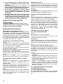
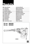
GB Rotary Hammer
Instruction Manual
F
Perforateur
Manuel d’instructions
D
Bohrhammer
Betriebsanleitung
I
Martello rotativo
Istruzioni per l’uso
NL Boorhamer
Gebruiksaanwijzing
E
Martillo rotativo
Manual de instrucciones
P
Martelo misto
Manual de instruções
DK Borehammer
Brugsanvisning
S
Borrhammare
Bruksanvisning
N
Borhammer
Bruksanvisning
SF Poravasara
Käyttöohje
GR Περιστροφικ
σφυρί
Οδηγίες χρήσεως
HR2450/T
HR2450X
HR2450F/FT
1
3
2
7
4
6
5
8
1
2
9
9
10
10
3
4
11
12
5
6
13
14
15
16
7
2
8
19
18
A
20
14
B
17
9
10
23
21
19
20
22
11
12
11
12
24
25
13
14
15
16
3
26
17
18
29
28
30
27
19
4
31
21
32
20
ENGLISH
Explanation of general view
1
2
3
4
5
6
7
8
9
10
11
Grip base
Side grip (auxiliary handle)
Teeth
Protrusions
Loosen
Tighten
Bit shank
Bit grease
Bit
Chuck cover
Action mode changing knob
12
13
14
15
16
17
18
19
20
21
22
Lock button
Depth gauge
Switch trigger
Lock button
Lamp (HR2450F only)
Reversing switch lever
Tool holder
Change cover line
Change cover
Drill chuck assembly
Spindle
23
24
25
26
27
28
29
30
31
32
Rotation with hammering
Hammering only
Rotation only
Dust cup
Keyless drill chuck
Chuck adapter
Sleeve
Tighten
Loosen
Ring
SPECIFICATIONS
Model
HR2450/X/F
Capacities
Concrete ..................................................................... 24 mm
Core bit ....................................................................... 54 mm
Diamond core bit ........................................................ 65 mm
Wood .......................................................................... 32 mm
Steel ........................................................................... 13 mm
No load speed (min-1).................................................... 0 – 1,100
Blows per minute ........................................................... 0 – 4,500
Overall length ................................................................ 360mm
Net weight...................................................................... 2.4 kg
• Due to our continuing program of research and development, the specifications herein are subject to change
without notice.
• Note: Specifications may differ from country to country.
Intended use
The tool is intended for hammer drilling and drilling in
brick, concrete and stone as well as for chiseling work.
It is also suitable for drilling without impact in wood,
metal, ceramic and plastic.
Power supply
The tool should be connected only to a power supply of
the same voltage as indicated on the nameplate, and can
only be operated on single-phase AC supply. They are
double-insulated in accordance with European Standard
and can, therefore, also be used from sockets without
earth wire.
Safety hints
For your own safety, please refer to the enclosed safety
instructions.
SPECIFIC SAFETY RULES
4.
5.
6.
7.
8.
9.
10.
11.
GEB007-2
DO NOT let comfort or familiarity with product
(gained from repeated use) replace strict adherence
to rotary hammer safety rules. If you use this tool
unsafely or incorrectly, you can suffer serious personal injury.
1. Wear ear protectors. Exposure to noise can cause
hearing loss.
2. Use auxiliary handles supplied with the tool.
Loss of control can cause personal injury.
3. Hold power tools by insulated gripping surfaces
when performing an operation where the cutting
tool may contact hidden wiring or its own cord.
Contact with a “live” wire will make exposed metal
parts of the tool “live” and shock the operator.
12.
13.
14.
HR2450T/FT
24 mm
54 mm
65 mm
32 mm
13 mm
0 – 1,100
0 – 4,500
384mm
2.6 kg
Wear a hard hat (safety helmet), safety glasses
and/or face shield. Ordinary eye or sun glasses
are NOT safety glasses. It is also highly recommended that you wear a dust mask and thickly
padded gloves.
Be sure the bit is secured in place before operation.
Under normal operation, the tool is designed to
produce vibration. The screws can come loose
easily, causing a breakdown or accident. Check
tightness of screws carefully before operation.
In cold weather or when the tool has not been
used for a long time, let the tool warm up for a
while by operating it under no load. This will
loosen up the lubrication. Without proper warmup, hammering operation is difficult.
Always be sure you have a firm footing.
Be sure no one is below when using the tool in
high locations.
Hold the tool firmly with both hands.
Keep hands away from moving parts.
Do not leave the tool running. Operate the tool
only when hand-held.
Do not point the tool at any one in the area when
operating. The bit could fly out and injure someone seriously.
Do not touch the bit or parts close to the bit
immediately after operation; they may be
extremely hot and could burn your skin.
Some material contains chemicals which may be
toxic. Take caution to prevent dust inhalation
and skin contact. Follow material supplier safety
data.
SAVE THESE INSTRUCTIONS.
5
WARNING:
MISUSE or failure to follow the safety rules stated in
this instruction manual may cause serious personal
injury.
Lighting up the lamps (Fig. 8)
OPERATING INSTRUCTIONS
To turn on the lamp, pull the trigger. Release the trigger
to turn it off.
Side grip (auxiliary handle) (Fig. 1)
Always use the side grip to ensure operating safety.
Install the side grip so that the teeth on the grip fit in
between the protrusions on the tool barrel. Then tighten
the grip by turning clockwise at the desired position. It
may be swung 360° so as to be secured at any position.
Installing or removing the bit
CAUTION:
Always be sure that the tool is switched off and
unplugged before installing or removing the bit.
Clean the bit shank and apply bit grease before installing
the bit. (Fig. 2)
Insert the bit into the tool. Turn the bit and push it in until
it engages. (Fig. 3)
After installing, always make sure that the bit is securely
held in place by trying to pull it out.
To remove the bit, pull the chuck cover down all the way
and pull the bit out. (Fig. 4)
Bit angle (when chipping, scaling or demolishing)
CAUTION:
Always be sure that the tool is switched off and
unplugged before changing the bit angle.
The bit can be secured at the desired angle. To change
the bit angle, depress the lock button and rotate the
action mode changing knob to the O symbol. Turn the
bit to the desired angle. (Fig. 5)
Depress the lock button and rotate the action mode
changing knob to the g symbol. Then make sure that
the bit is securely held in place by turning it slightly.
(Fig. 6)
Depth gauge (Fig. 7)
The depth gauge is convenient for drilling holes of uniform depth. Loosen the side grip and insert the depth
gauge into the hole in the side grip. Adjust the depth
gauge to the desired depth and tighten the side grip.
NOTE:
The depth gauge cannot be used at the position where
the depth gauge strikes against the gear housing.
Switch action (Fig. 8)
CAUTION:
Before plugging in the tool, always check to see that the
switch trigger actuates properly and returns to the “OFF”
position when released.
To start the tool, simply pull the switch trigger. Tool speed
is increased by increasing pressure on the switch trigger.
Release the switch trigger to stop. For continuous operation, pull the switch trigger and then push in the lock button. To stop the tool from the locked position, pull the
switch trigger fully, then release it.
For model HR2450F, HR2450FT
CAUTION:
Do not look in the light or see the source of light directly.
NOTE:
Use a dry cloth to wipe the dirt off the lens of lamp. Be
careful not to scratch the lens of lamp, or it may lower the
illumination.
Reversing switch action (Fig. 9)
This tool has a reversing switch to change the direction of
rotation. Move the reversing switch lever to the D position (A side) for clockwise rotation or the E position
(B side) for counterclockwise rotation.
CAUTION:
• Always check the direction of rotation before operation.
• Use the reversing switch only after the tool comes to a
complete stop. Changing the direction of rotation
before the tool stops may damage the tool.
• When you operate the tool in counterclockwise rotation,
the switch trigger is pulled only halfway and the tool
runs at half speed. For counterclockwise rotation, you
cannot push in the lock button.
Changing the quick change chuck for SDS-plus
(Fig. 10 & 11)
For model HR2450T/HR2450FT
The quick change chuck for SDS-plus can be easily
exchanged for the quick change drill chuck.
Removing the quick change chuck for SDS-plus
CAUTION:
• Before removing the quick change chuck for SDS-plus,
always remove the bit.
Grasp the change cover of the quick change chuck for
SDS-plus and turn in the direction of the arrow until the
change cover line moves from the
symbol to the
symbol. Pull forcefully in the direction of the arrow.
Attaching the quick change drill chuck
Check the line of the quick change drill chuck shows the
symbol. Grasp the change cover of the quick change
drill chuck and set the line to the
symbol. Place the
quick change drill chuck on the spindle of the tool.
Grasp the change cover of the quick change drill chuck
and turn the change cover line to the
symbol until a
click can clearly be heard.
Selecting action mode
Rotation with hammering (Fig. 12)
For drilling in concrete, masonry, etc., depress the lock
button and rotate the action mode changing knob to the
H symbol. Use a tungsten-carbide tipped bit.
Hammering only (Fig. 13)
For chipping, scaling or demolition operations, depress
the lock button and rotate the action mode changing
knob to the g symbol. Use a bull point, cold chisel, scaling chisel, etc.
Rotation only (Fig. 14)
For drilling in wood, metal or plastic materials, depress
the lock button and rotate the action mode changing
knob to the m symbol. Use a twist drill bit or wood bit.
6
CAUTION:
• Do not rotate the action mode changing knob when the
tool is running under load. The tool will be damaged.
• To avoid rapid wear on the mode change mechanism,
be sure that the action mode changing knob is always
positively located in one of the three action mode positions.
Chipping/Scaling/Demolition (Fig. 18)
Set the action mode changing knob to the g symbol.
Hold the tool firmly with both hands. Turn the tool on and
apply slight pressure on the tool so that the tool will not
bounce around, uncontrolled. Pressing very hard on the
tool will not increase the efficiency.
Drilling in wood or metal
Torque limiter
The torque limiter will actuate when a certain torque level
is reached. The motor will disengage from the output
shaft. When this happens, the bit will stop turning.
CAUTION:
• As soon as the torque limiter actuates, switch off the
tool immediately. This will help prevent premature wear
of the tool.
• Hole saws cannot be used with this tool. They tend to
pinch or catch easily in the hole. This will cause the
torque limiter to actuate too frequently.
Hammer drilling operation (Fig. 15)
Set the action mode changing knob to the H symbol.
Position the bit at the desired location for the hole, then
pull the trigger.
Do not force the tool. Light pressure gives best results.
Keep the tool in position and prevent it from slipping away
from the hole.
Do not apply more pressure when the hole becomes
clogged with chips or particles. Instead, run the tool at an
idle, then remove the bit partially from the hole. By
repeating this several times, the hole will be cleaned out
and normal drilling may be resumed.
CAUTION:
There is tremendous and sudden twisting force exerted
on the tool/bit at the time of hole breakthrough, when the
hole becomes clogged with chips and particles, or when
striking reinforcing rods embedded in the concrete.
Always use the side grip (auxiliary handle) and firmly
hold the tool by both side grip and switch handle during
operations. Failure to do so may result in the loss of control of the tool and potentially severe injury.
For model HR2450/HR2450F/HR2450X (Fig. 19)
Use the optional drill chuck assembly. When installing it,
refer to “Installing or removing drill bit” described on the
previous page.
For model HR2450T/HR2450FT (Fig. 11)
Use the drill chuck assembly as standard equipment.
When installing it, refer to “Changing the tool holder”
described on the previous page.
Hold the ring and turn the sleeve counterclockwise to
open the chuck jaws. Place the bit in the chuck as far as
it will go. Hold the ring firmly and turn the sleeve clockwise to tighten the chuck.
To remove the bit, hold the ring and turn the sleeve counterclockwise. (Fig. 20)
NOTE:
Eccentricity in the bit rotation may occur while operating
the tool with no load. The tool automatically centers itself
during operation. This does not affect the drilling precision.
Set the action mode changing knob to the m symbol. You
can drill up to 13 mm diameter in metal and up to 32 mm
diameter in wood.
CAUTION:
• Never use “rotation with hammering” when the drill
chuck assembly is installed on the tool. The drill chuck
assembly may be damaged.
Also, the drill chuck will come off when reversing the
tool.
• Pressing excessively on the tool will not speed up the
drilling. In fact, this excessive pressure will only serve
to damage the tip of your bit, decrease the tool performance and shorten the service life of the tool.
• There is a tremendous twisting force exerted on the
tool/bit at the time of hole breakthrough. Hold the tool
firmly and exert care when the bit begins to break
through the workpiece.
• A stuck bit can be removed simply by setting the
reversing switch to reverse rotation in order to back out.
However, the tool may back out abruptly if you do not
hold it firmly.
• Always secure small workpieces in a vise or similar
hold-down device.
Bit grease
Diamond core drilling
Coat the bit shank head beforehand with a small amount
of bit grease (about 0.5 – 1 g).
This chuck lubrication assures smooth action and longer
service life.
When performing diamond core drilling operations,
always set the change lever to the m position to use “rotation only” action.
CAUTION:
If performing diamond core drilling operations using
“rotation with hammering” action, the diamond core bit
may be damaged.
Blow-out bulb (Fig. 16)
Use the blow-out bulb to clean out the hold.
Dust cup (Fig. 17)
Use the dust cup to prevent dust from falling over the tool
and on yourself when performing overhead drilling operations. Attach the dust cup to the bit as shown in Fig. 17.
The size of bits which the dust cup can be attached to is
as follows.
Bit diameter (mm)
Dust cup 5
6 – 14.5
Dust cup 9
12 – 16
MAINTENANCE
CAUTION:
Always be sure that the tool is switched off and
unplugged before carrying out any work on the tool.
To maintain product safety and reliability, repairs, maintenance or adjustment should be carried out by a Makita
Authorized Service Center.
7
ACCESSORIES
CAUTION:
These accessories or attachments are recommended for
use with your Makita tool specified in this manual. The
use of any other accessories or attachments might
present a risk of injury to persons. Only use accessory or
attachment for its stated purpose.
If you need any assistance for more details regarding
these accessories, ask your local Makita service center.
•
•
•
•
•
•
•
•
•
•
•
•
•
•
•
•
•
•
8
Depth gauge
Side grip
Plastic carrying case
Blow-out bulb
Dust cup
Bull point
Cold chisel
Scaling chisel
Grooving chisel
SDS Plus tungsten-carbide tipped bit
Drill chuck
Chuck adapter
Drill chuck assembly
Keyless drill chuck
Chuck key
Bit grease
Dust extractor attachment
Safety goggles
NEDERLANDS
Verklaring van algemene gegevens
1
2
3
4
5
6
7
8
9
10
11
Handgreepvoet
Zijhandgreep (hulphandgreep)
Tanden
Nokken
Losdraaien
Vastzetten
Boorschacht
Boorvet
Boor
Boorkopdeksel
Omschakelknop
12
13
14
15
16
17
18
19
20
21
22
Vastzetknop
Dieptemaat
Trekschakelaar
Vastzetknop
Lamp (alleen voor HR2450F)
Omkeerschakelaarknop
Gereedschapshouder
Streep op wisseldeksel
Wisseldeksel
Boorkopmontage
As
23
24
25
26
27
28
29
30
31
32
Boren plus hameren
Alleen hameren
Alleen boren
Stofvanger
Sleutelloze boorkop
Boorkop-adapter
Bus
Vastzetten
Losdraaien
Ring
TECHNISCHE GEGEVENS
Model
HR2450/X/F
Vermogen
Beton .......................................................................... 24 mm
Kroonboor................................................................... 54 mm
Diamant kroonboor ..................................................... 65 mm
Hout ............................................................................ 32 mm
Staal ........................................................................... 13 mm
Nullasttoerental (min-1).................................................. 0 – 1 100
Aantal slagen/minuut ..................................................... 0 – 4 500
Totale lengte .................................................................. 360 mm
Netto gewicht ................................................................. 2,4 kg
• In verband met ononderbroken research en ontwikkeling behouden wij ons het recht voor bovenstaande
technische gegevens te wijzigen zonder voorafgaande
kennisgeving.
• Opmerking: De technische gegevens kunnen van land
tot land verschillen.
Doeleinden van gebruik
Dit gereedschap is bedoeld voor hamerboren en boren in
baksteen, beton en steen, en ook voor beitelen.
Het gereedschap is ook geschikt voor boren zonder slag
in hout, metaal, keramisch materiaal en kunststof.
Stroomvoorziening
Het gereedschap mag alleen worden aangesloten op
een stroombron van hetzelfde voltage als aangegeven op
de naamplaat, en kan alleen op enkel-fase wisselstroom
worden gebruikt. Het gereedschap is dubbel-geïsoleerd
volgens de Europese standaard en kan derhalve ook op
een niet-geaard stopcontact worden aangesloten.
Veiligheidswenken
Voor uw veiligheid dient u de bijgevoegde Veiligheidsvoorschriften nauwkeurig op te volgen.
AANVULLENDE
VEILIGHEIDSVOORSCHRIFTEN
Laat u NIET misleiden door een vals gevoel van comfort en bekendheid met het gereedschap (na veelvuldig gebruik) en neem alle veiligheidsvoorschriften
van de boorhamer altijd strikt in acht. Bij onveilig of
verkeerd gebruik van het gereedschap, bestaat de
kans op ernstig persoonlijk letsel.
1. Draag gehoorbescherming. Blootstelling aan
harde geluiden kan leiden tot gehoorbeschadiging.
2. Gebruik de hulphandgrepen die bij het gereedschap werden geleverd. Als u de controle over het
gereedschap verliest, kan dit leiden tot ernstig persoonlijk letsel.
HR2450T/FT
24 mm
54 mm
65 mm
32 mm
13 mm
0 – 1 100
0 – 4 500
384 mm
2,6 kg
3.
Houd elektrisch gereedschap vast aan het geïsoleerde oppervlak van de handgrepen wanneer u
werkt op plaatsen waar het zaaggereedschap
met verborgen bedrading of zijn eigen snoer in
aanraking kan komen. Door contact met onder
spanning staande draden, zullen de niet-geïsoleerde metalen delen van het gereedschap onder
spanning komen te staan zodat de gebruiker een
elektrische schok kan krijgen.
4. Draag een veiligheidshelm, veiligheidsbril en/of
gezichtsbescherming. Een gewone bril of een
zonnebril is GEEN veiligheidsbril. Het wordt
tevens sterk aanbevolen een stofmasker en dik
gevoerde handschoenen te dragen.
5. Controleer dat het bit stevig op zijn plaats is
vastgezet voordat u het gereedschap gebruikt.
6. Bij normale bediening behoort het gereedschap
te trillen. De schroeven kunnen gemakkelijk losraken, waardoor een defect of ongeluk kan ontstaan. Controleer of de schroeven goed zijn
aangedraaid, alvorens het gereedschap te
gebruiken.
7. In koude weersomstandigheden of wanneer het
gereedschap gedurende een lange tijd niet is
gebruikt, laat u het gereedschap eerst opwarmen
door het onbelast te laten werken. Hierdoor zal
de smering worden verbeterd. Zonder degelijk
opwarmen, zal de hamerwerking moeilijk zijn.
8. Zorg er altijd voor dat u stevig staat.
Zorg ervoor dat er niemand zich onder u bevindt
wanneer u het gereedschap op een hoge plaats
gebruikt.
9. Houd het gereedschap met beide handen stevig
vast.
10. Houd uw handen uit de buurt van bewegende
delen.
21
11. Laat het gereedschap niet ingeschakeld liggen.
Bedien het gereedschap alleen wanneer u het
vasthoudt.
12. Richt het gereedschap niet op iemand in de
buurt terwijl het is ingeschakeld. Het bit zou eruit
kunnen vliegen en iemand ernstig verwonden.
13. Raak het bit en onderdelen in de buurt van het
bit niet onmiddellijk na gebruik aan. Zij kunnen
bijzonder heet zijn en brandwonden op uw huid
veroorzaken.
14. Sommige materialen bevatten chemische stoffen
die giftig kunnen zijn. Neem de nodige voorzorgsmaatregelen tegen inademing van stof en
contact met de huid. Volg de veiligheidsinstructies van de leverancier van het materiaal op.
Diepteaanslag (Fig. 7)
BEWAAR DEZE VOORSCHRIFTEN.
BEDIENINGSVOORSCHRIFTEN
Om de machine te starten, drukt u gewoon de trekschakelaar in. Hoe dieper de trekschakelaar wordt ingedrukt,
hoe sneller de machine draait. Om de machine uit te
schakelen, de trekschakelaar loslaten. Voor continuë
werking, drukt u de trekschakelaar in en dan drukt u de
vastzetknop in. Om de machine vanuit deze vergrendelde stand te stoppen, de trekschakelaar volledig
indrukken en deze dan loslaten.
Zijhandgreep (hulphandgreep) (Fig. 1)
Aanzetten van de lampen (Fig. 8)
Gebruik altijd de zijhandgreep om een veilige bediening
te verzekeren. Installeer de zijhandgreep zodanig dat de
tanden op de greep tussen de nokken op het huis van de
machine komen te zitten. Zet dan de handgreep vast
door deze in de gewenste positie naar rechts te draaien.
De handgreep kan 360° worden verdraaid zodat u deze
in elke gewenste positie kunt vastzetten.
Voor model HR2450F/HR2450FT
WAARSCHUWING:
VERKEERD GEBRUIK of het niet naleven van de
veiligheidsvoorschriften in deze gebruiksaanwijzing
kan leiden tot ernstige verwondingen.
Aanbrengen of verwijderen van de boor
LET OP:
Controleer altijd of het gereedschap is uitgeschakeld en
zijn stekker uit het stopcontact is verwijderd alvorens de
boor aan te brengen of te verwijderen.
Reinig de boorschacht en smeer er boorvet op alvorens
de boor te installeren. (Fig. 2)
Steek de boor in de machine. Draai de boor en duw deze
naar binnen tot zij vergrendelt. (Fig. 3)
Nadat de boor is geïnstalleerd, moet u altijd controleren
of de boor goed vastzit door te proberen hem eruit te
trekken.
Om de boor te verwijderen, trekt u het boorkopdeksel
helemaal omlaag en dan trekt u de boor eruit. (Fig. 4)
Boorhoek (voor beitelen, afbikken of slopen)
LET OP:
Zorg altijd dat het gereedschap is uitgeschakeld en de
stekker uit het stopcontact is verwijderd voordat u de
boorhoek wijzigt.
De boor kan bij de gewenste hoek worden vastgezet. Om
de boorhoek te wijzigen, drukt u de vergrendelknop in en
draait u de werkingskeuzeknop zodat de wijzer naar het O
symbool wijst. Draai de boor naar de gewenste hoek.
(Fig. 5)
Druk de vergrendelknop in en draai de werkingskeuzeknop zodat de wijzer naar het g symbool wijst. Draai
daarna de boor een beetje om te controleren of deze
goed vastzit. (Fig. 6)
22
De diepteaanslag is handig voor het boren van gaten van
gelijke diepte. Maak de zijhandgreep los en steek de
diepteaanslag in het gat in de zijhandgreep. Stel de diepteaanslag af op de gewenste diepte en zet de zijhandgreep vast.
OPMERKING:
De diepteaanslag kan niet worden gebruikt in de positie
waarbij deze tegen het tandwielhuis aanstoot.
Werking van de trekschakelaar (Fig. 8)
LET OP:
Alvorens de machine op een stopcontact aan te sluiten,
moet u altijd controleren of de trekschakelaar juist werkt
en bij het loslaten naar de “OFF” positie terugkeert.
LET OP:
Kijk niet direct in het licht of de lichtbron.
Druk de trekker in om de lamp aan te zetten. Laat de
trekker los om de lamp uit te doen.
OPMERKING:
Gebruik een droge doek om vuil op de lamplens eraf te
vegen. Let op dat u geen krassen maakt op de lamplens,
aangezien de verlichtingssterkte daardoor zal verminderen.
Werking van de omkeerschakelaar (Fig. 9)
Dit gereedschap heeft een omkeerschakelaar voor het
veranderen van de draairichting. Beweeg de omkeerschakelaar naar de positie D (kant A) voor rechtse
draairichting, of naar de positie E (kant B) voor linkse
draairichting.
LET OP:
• Controleer altijd de draairichting alvorens de machine
te gebruiken.
• Gebruik de omkeerschakelaar alleen nadat de machine
volledig tot stilstand is gekomen. Indien u de draairichting verandert voordat de machine is gestopt, kan de
machine beschadigd raken.
• Wanneer u het gereedschap in linkse draairichting
gebruikt, kan de trekschakelaar alleen tot halverwege
worden ingedrukt en draait het gereedschap op halve
snelheid. Voor linkse draairichting kunt u de vergrendelknop niet indrukken.
De snelkoppelingboorkop voor SDS-plus
vervangen (Fig. 10 en 11)
Voor model HR2450T/HR2450FT
De snelkoppelingboorkop voor SDS-plus kan eenvoudig
vervangen worden door de gewone snelkoppelingboorkop.
De snelkoppelingboorkop voor SDS-plus eraf halen
LET OP:
• Haal altijd eerst de bit eruit voordat u de snelkoppelingboorkop voor SDS-plus eraf haalt.
Pak het wisseldeksel van de snelkoppelingboorkop voor
SDS-plus beet en draai deze in de richting van de pijl totdat de streep op het wisseldeksel wordt verplaatst van
het
symbool naar het
symbool. Trek vervolgens
krachtig in de richting van de pijl.
Forceer het gereedschap niet. Een lichte druk geeft de
beste resultaten. Houd het gereedschap stevig vast en
zorg dat het niet uitglijdt.
Oefen geen grotere druk uit wanneer het boorgat verstopt raakt met schilfertjes of metaaldeeltjes. Laat in zo’n
geval het gereedschap onbelast lopen en verwijder de
boor gedeeltelijk uit het boorgat. Wanneer dit verschillende keren wordt herhaald, zal het boorgat schoon worden en kunt u normaal verder boren.
Kiezen van de gewenste werking
LET OP:
Op het moment dat een gat wordt geboord, of wanneer
het boorgat verstopt raakt met schilfertjes en metaaldeeltjes, of wanneer de machine op versterkingsstaven in
gewapend beton stoot, wordt er plotseling een enorme
wringingskracht op de machine/boor uitgeoefend.
Gebruik daarom altijd de zijhandgreep (hulphandgreep)
en houd de machine tijdens het gebruik stevig vast bij
zowel de zijhandgreep als de hoofdhandgreep. Indien u
dit verzuimt, kunt u de controle over de machine verliezen en mogelijk zware verwondingen oplopen.
Boren plus hameren (Fig. 12)
Voor boren in beton, metselwerk e.d., drukt u de vergrendelknop in en draait u de werkingskeuzeknop zodat de
wijzer naar het H symbool wijst. Gebruik een boor met
een wolfraamcarbide punt.
OPMERKING:
Terwijl het gereedschap onbelast wordt gebruikt, kan de
boor excentrisch draaien. Het gereedschap centreert
zichzelf automatisch tijdens het gebruik. Dit heeft geen
nadelige invloed op de nauwkeurigheid van het boren.
Alleen hameren (Fig. 13)
Voor beitelen, afbikken of slopen, drukt u de vergrendelknop in en draait u de werkingskeuzeknop zodat de wijzer naar het g symbool wijst. Gebruik een puntbeitel,
koudbeitel, bikbeitel, enz.
Invetten van de boor
Alleen boren (Fig. 14)
Voor boren in hout, metaal of kunststof, drukt u de vergrendelknop in en draait u de werkingskeuzeknop zodat
de wijzer naar het m symbool wijst. Gebruik een spiraalboor of een houtboor.
Blaasbalgje (Fig. 16)
De gewone snelkoppelingboorkop erop zetten
Controleer of de streep op de gewone snelkoppelingboorkop op het
symbool staat. Pak het wisseldeksel
van de gewone snelkoppelingboorkop beet en lijn de
streep uit met het
symbool. Plaats de gewone snelkoppelingboorkop op de as van het gereedschap.
Pak het wisseldeksel van de gewone snelkoppelingboorkop beet en verplaats de streep op het wisseldeksel naar
het
symbool totdat u duidelijk een klik hoort.
LET OP:
• Wijzig de positie van de werkingskeuzeknop niet terwijl
het gereedschap nog belast draait, aangezien het
gereedschap daardoor beschadigd zal raken.
• Om vroegtijdige slijtage van het wisselmechanisme te
voorkomen, dient u de werkingskeuzeknop altijd juist
op een van de drie werkingsposities te zetten.
Koppelbegrenzer
De koppelbegrenzer treedt in werking wanneer de motor
een bepaald koppel bereikt. De motor wordt dan ontkoppeld van de uitgangsas. Wanneer dit gebeurt, zal de boor
ophouden met draaien.
LET OP:
• Schakel het gereedschap onmiddellijk uit wanneer de
koppelbegrenzer in werking treedt. Hierdoor helpt u
vroegtijdige slijtage van het gereedschap voorkomen.
• Gatenzagen kunnen met dit gereedschap niet worden
gebruikt. Deze lopen of klemmen gemakkelijk vast in
het boorgat, zodat de koppelbegrenzer te vaak in werking zal worden gesteld.
Hamerend of kloppend boren (Fig. 15)
Draai de werkingskeuzeknop zodat de wijzer naar het H
symbool wijst.
Plaats de punt van de boor op de gewenste plaats waar
geboord moet worden, en druk vervolgens de schakelaar
in.
Voordat u de boor aanbrengt, smeer een beetje vet
(ca. 0,5 tot 1,0 gram) op de kop van de boorschacht.
Met een ingevette boorkop zal het gereedschap beter
werken en langer meegaan.
Gebruik het blaasbalgje om het gat schoon te maken.
Stofvanger (Fig. 17)
Gebruik de stofvanger om te voorkomen dat stof op de
machine en op uzelf terechtkomt wanneer u boven uw
hoofd boort. Bevestig de stofvanger aan de boor, zoals
getoond in Fig. 17. De diameter van de boren waaraan
de stofvanger kan worden bevestigd, is als volgt.
Boordiameter (mm)
Stofvanger 5
6 – 14,5
Stofvanger 9
12 – 16
Beitelen/Afbikken/Slopen (Fig. 18)
Draai de werkingskeuzeknop zodat de wijzer naar het g
symbool wijst. Houd de machine met beide handen stevig vast. Schakel de machine in en oefen niet meer druk
uit op de machine dan nodig is om deze onder controle te
houden. Door grote kracht op de machine uit te oefenen
verloopt het werk niet sneller.
Boren in hout of metaal
Voor model HR2450/HR2450F/HR2450X (Fig. 19)
Gebruik de los verkrijgbare boorkopmontage. Om deze
te installeren, zie “Aanbrengen of verwijderen van de
boor” op de vorige pagina.
Voor model HR2450T/HR2450FT (Fig. 11)
Gebruik de boorkopmontage als standaard uitrusting.
Voor aanwijzingen over het installeren van de boorkopmontage, zie “Verwisselen van de gereedschapshouder”
op de vorige bladzijde.
23
Houd de ring vast en draai de bus naar links om de klauwen van de boorkop te openen. Steek de boor zo ver
mogelijk in de boorkop. Houd de ring weer stevig vast en
draai de bus naar rechts om de boorkop vast te zetten.
Om de boor te verwijderen, houdt u de ring vast en draait
u de bus naar links. (Fig. 20)
ONDERHOUD
Draai de werkingskeuzeknop zodat de wijzer naar het m
symbool wijst. U kunt boren tot een diameter van maximaal 13 mm in metaal en een diameter van maximaal
32 mm in hout.
Opdat het gereedschap veilig en betrouwbaar blijft, dienen alle reparaties, onderhoud of afstellingen te worden
uitgevoerd bij een erkend Makita service centrum.
LET OP:
• Gebruik nooit “roteren met hameren” wanneer de boorkop op het gereedschap is gemonteerd. De boorkop
kan hierdoor namelijk beschadigd raken.
Bovendien zal de boorkop loskomen wanneer de draairichting van het gereedschap wordt omgekeerd.
• Door teveel druk op het gereedschap uit te oefenen
verloopt het boren niet sneller. Integendeel, teveel druk
op het gereedschap zal alleen maar de boor beschadigen, de prestatie van het gereedschap verminderen en
de gebruiksduur verkorten.
• Er ontstaan enorme spanningen op het ogenblik dat de
boor uit het gat tevoorschijn komt. Houd derhalve het
gereedschap stevig vast en wees op uw hoede.
• Wanneer de boor klemraakt, keert u met de omkeerschakelaar de draairichting om, om de boor uit het gat
te krijgen. Pas echter op en houd het gereedschap stevig vast, aangezien het anders uit het gat weg kan
schieten.
• Kleine werstukken dient u altijd eerst vast te zetten met
een klemschroef of iets dergelijks.
ACCESSOIRES
Boren met de diamant kroonboor
Voor boren met de diamant kroonboor dient de boorwerkingskeuzehendel altijd in de m positie voor “alleen
boren” te worden gezet.
LET OP:
Indien u de diamant kroonboor gebruikt voor “hamerend
boren”, kan de diamant kroonboor beschadigd raken.
24
LET OP:
Zorg er altijd voor dat het gereedschap is uitgeschakeld
en de stekker uit het stopcontact is verwijderd alvorens
werken aan de machine uit te voeren.
LET OP:
Deze accessoires of hulpstukken worden aanbevolen
voor gebruik met het Makita gereedschap dat in deze
gebruiksaanwijzing wordt beschreven. Het gebruik van
andere accessoires of hulpstukken kan gevaar voor persoonlijke verwonding opleveren. Gebruik de accessoires
of hulpstukken uitsluitend voor het gespecificeerde doel.
Wenst u meer informatie over deze accessoires, neem
dan contact op met het dichtstbijzijnde Makita servicecentrum.
•
•
•
•
•
•
•
•
•
•
•
•
•
•
•
•
•
•
Dieptemaat
Zijhandgreep
Plastic draagtas
Blaasbalgje
Stofvanger
Puntbeitel
Koudbeitel
Bikbeitel
Sponningbeitel
Boor met SDS Plus wolfraamcarbide boorpunt
Boorkop
Boorkop-adapter
Boorkopmontage
Sleutelloze boorkop
Boorkopsleutel
Boorvet
Hulpstuk voor stofafscheiding
Veiligheidsbril
ENH101-5
ENGLISH
ITALIANO
EC-DECLARATION OF CONFORMITY
DICHIARAZIONE DI CONFORMITÀ
CON LE NORME DELLA COMUNITÀ EUROPEA
We declare under our sole responsibility that this product
is in compliance with the following standards of standardized documents,
EN60745, EN55014, EN61000
in accordance with Council Directives, 89/336/EEC and
98/37/EC.
Dichiariamo sotto la nostra sola responsabilità che
questo prodotto è conforme agli standard di documenti
standardizzati seguenti:
EN60745, EN55014, EN61000
secondo le direttive del Consiglio 89/336/CEE e 98/37/CE.
FRANÇAISE
NEDERLANDS
DÉCLARATION DE CONFORMITÉ CE
EG-VERKLARING VAN CONFORMITEIT
Nous déclarons sous notre entière responsabilité que ce
produit est conforme aux normes des documents standardisés suivants,
EN60745, EN55014, EN61000
conformément aux Directives du Conseil, 89/336/CEE et
98/37/EG.
Wij verklaren hierbij uitsluitend op eigen verantwoordelijkheid dat dit produkt voldoet aan de volgende
normen van genormaliseerde documenten,
EN60745, EN55014, EN61000
in overeenstemming met de richtlijnen van de Raad
89/336/EEC en 98/37/EC.
DEUTSCH
ESPAÑOL
CE-KONFORMITÄTSERKLÄRUNG
DECLARACIÓN DE CONFORMIDAD DE LA CE
Hiermit erklärt wir unter unserer alleinigen Verantwortung, daß dieses Produkt gemäß den Ratsdirektiven
89/336/EWG und 98/37/EG mit den folgenden Normen
von Normendokumenten übereinstimmen:
EN60745, EN55014, EN61000.
Declaramos bajo nuestra sola responsabilidad que este
producto cumple con las siguientes normas de documentos normalizados,
EN60745, EN55014, EN61000
de acuerdo con las directivas comunitarias,
89/336/EEC y 98/37/CE.
Yasuhiko Kanzaki CE 2005
Director
Directeur
Direktor
Amministratore
Directeur
Director
MAKITA INTERNATIONAL EUROPE LTD.
Michigan Drive, Tongwell, Milton Keynes,
Bucks MK15 8JD, ENGLAND
Responsible manufacturer:
Fabricant responsable :
Verantwortlicher Hersteller:
Produttore responsabile:
Verantwoordelijke fabrikant:
Fabricante responsable:
Makita Corporation Anjo Aichi Japan
54
ENH101-5
PORTUGUÊS
NORSK
DECLARAÇÃO DE CONFORMIDADE DA CE
EUs SAMSVARS-ERKLÆRING
Declaramos sob inteira responsabilidade que este
produto obedece às seguintes normas de documentos
normalizados,
EN60745, EN55014, EN61000
de acordo com as directivas 89/336/CEE e 98/37/CE do
Conselho.
Vi erklærer på eget ansvar at dette produktet er i overensstemmelse med følgende standard i de standardiserte dokumenter:
EN60745, EN55014, EN61000,
i samsvar med Råds-direktivene, 89/336/EEC og
98/37/EC.
DANSK
SUOMI
EU-DEKLARATION OM KONFORMITET
VAKUUTUS EC-VASTAAVUUDESTA
Vi erklærer hermed på eget ansvar, at dette produkt er i
overensstemmelse med de følgende standarder i de normsættende dokumenter,
EN60745, EN55014, EN61000
i overensstemmelse med Rådets Direktiver 89/336/EEC
og 98/37/EC.
Yksinomaisesti vastuullisina ilmoitamme, että tämä tuote
on seuraavien standardoitujen dokumenttien standardien mukainen,
EN60745, EN55014, EN61000
neuvoston direktiivien 89/336/EEC ja 98/37/EC mukaisesti.
SVENSKA
ΕΛΛΗΝΙΚΑ
EG-DEKLARATION OM ÖVERENSSTÄMMELSE
∆ΗΛΩΣΗ ΣΥΜΜΟΡΦΩΣΗΣ ΕΚ
Under eget ansvar deklarerar vi härmed att denna
produkt överensstämmer med följande standardiseringar
för standardiserade dokument,
EN60745, EN55014, EN61000
i enlighet med EG-direktiven 89/336/EEC och 98/37/EC.
∆ηλώνουµε υπ την µοναδική µας ευθύνη τι αυτ
το προιν βρίσκεται σε Συµφωνία µε τα ακλουθα
πρτυπα τυποποιηµένων εγγράφων,
EN60745, EN55014, EN61000
σύµφωνα µε τις Οδηγίες του Συµβουλίου,
89/336/EEC και 98/37/ΚE.
Yasuhiko Kanzaki CE 2005
Director
Direktør
Direktör
Direktor
Johtaja
∆ιευθυντής
MAKITA INTERNATIONAL EUROPE LTD.
Michigan Drive, Tongwell, Milton Keynes,
Bucks MK15 8JD, ENGLAND
Fabricante responsável:
Ansvarlig fabrikant:
Ansvarig tillverkare:
Ansvarlig produsent:
Vastaava valmistaja:
Υπεύθυνος κατασκευαστής:
Makita Corporation Anjo Aichi Japan
55
ENG006-2-V4
ENGLISH
ITALIANO
For European countries only
Modello per l’Europa soltanto
Noise and Vibration
The typical A-weighted noise levels are
sound pressure level: 89 dB (A)
sound power level: 100 dB (A)
Uncertainty is 3 dB (A).
– Wear ear protection. –
Rumore e vibrazione
I livelli del rumore pesati secondo la curva A sono:
Livello pressione sonora: 89 dB (A)
Livello potenza sonora:100 dB (A)
L’incertezza è di 3 dB (A).
– Indossare i paraorecchi. –
Il valore quadratico medio di accellerazione è di 9 m/s2.
Questi valori sono stati ottenuti in conformità EN60745.
The typical weighted root mean square acceleration
value is 9 m/s2.
These values have been obtained according to
EN60745.
FRANÇAISE
NEDERLANDS
Pour les pays d’Europe uniquement
Alleen voor Europese landen
Bruit et vibrations
Les niveaux de bruit ponderes types A sont:
niveau de pression sonore: 89 dB (A)
niveau de puissance du son: 100 dB (A)
L’incertitude de mesure est de 3 dB (A).
– Porter des protecteurs anti-bruit. –
L’accélération pondérée est de 9 m/s2.
Ces valeurs ont été obtenues selon EN60745.
Geluidsniveau en trilling
De typische A-gewogen geluidsniveau’s zijn
geluidsdrukniveau:89 dB (A)
geluidsenergie-niveau: 100 dB (A)
Onzekerheid is 3 dB (A).
– Draag oorbeschermers. –
De typische gewogen effectieve versnellingswaarde is
9 m/s2.
Deze waarden werden verkregen in overeenstemming
met EN60745.
DEUTSCH
ESPAÑOL
Nur für europäische Länder
Para países europeos solamente
Geräusch- und Vibrationsentwicklung
Die typischen A-bewerteten Geräuschpegel betragen:
Schalldruckpegel: 89 dB (A)
Schalleistungspegel: 100dB (A)
Die Abweichung beträgt 3 dB (A).
– Gehörschutz tragen. –
Der gewichtete Effektivwert der Beschleunigung beträgt
2
9 m/s .
Diese Werte wurden gemäß EN60745 erhalten.
Ruido y vibración
Los niveles típicos de ruido ponderados A son
presión sonora: 89 dB (A)
nivel de potencia sonora: 100 dB (A)
Incerteza 3 dB (A).
– Póngase protectores en los oídos. –
El valor ponderado de la aceleración es de 9 m/s2.
Estos valores han sido obtenidos de acuerdo con
EN60745.
56
ENG009-2-V4
PORTUGUÊS
NORSK
Só para países Europeus
Gjelder bare land i Europa
Ruído e vibração
Os níveis normais de ruído A são
nível de pressão de som: 89 dB (A)
nível do sum: 100 dB (A)
A incerteza é de 3 dB (A).
– Utilize protectores para os ouvidos –
O valor médio da aceleração é 9 m/s2.
Estes valores foram obtidos de acordo com EN60745.
Støy og vibrasjon
De vanlige A-belastede støynivå er
lydtrykksnivå: 89 dB (A)
lydstyrkenivå: 100 dB (A)
Usikkerheten er på 3 dB (A).
– Benytt hørselvern. –
Den vanlig belastede effektiv-verdi for akselerasjon er
2
9 m/s .
Disse verdiene er beregnet eller målt i samsvar med
EN60745.
DANSK
SUOMI
Kun for lande i Europa
Vain Euroopan maat
Lyd og vibration
De typiske A-vægtede lydniveauer er
lydtryksniveau: 89 dB (A)
lydeffektniveau: 100 dB (A)
Der er en usikkerhed på 3 dB (A).
– Bær høreværn. –
Den vægtede effektive accelerationsværdi er 9 m/s2.
Disse værdier er beregnet i overensstemmelse med
EN60745.
Melutaso ja tärinä
Tyypilliset A-painotetut melutasot ovat
äänenpainetaso: 89 dB (A)
äänen tehotaso: 100 dB (A)
Epävarmuus on 3 dB (A).
– Käytä kuulosuojaimia. –
Tyypillinen kiihtyvyyden painotettu tehollisarvo on
9 m/s2.
Nämä arvot on mitattu normin EN60745 mukaisesti.
SVENSKA
ΕΛΛΗΝΙΚΑ
Endast för Europa
Μ
νο για χώρες της Ευρώπης
Buller och vibration
De typiska A-vägda bullernivåerna är
ljudtrycksnivå: 89 dB (A)
ljudeffektnivå: 100 dB (A)
Osäkerheten är 3 dB (A).
– Använd hörselskydd –
Det typiskt vägda effektivvärdet för acceleration är
9 m/s2.
Dessa värden har erhållits i enlighet med EN60745.
Θ
ρυβος και κραδασµ
ς
Οι τυπικές A-µετρούµενες εντάσεις ήχου είναι
πίεση ήχου: 89 dB (A)
δύναµη του ήχου: 100dB (A)
Η Αβεβαιτητα είναι 3 dB (A).
– Φοράτε ωτοασπίδες. –
Η τυπική αξία της µετρούµενης ρίζας του µέσου
τετραγώνου της επιτάχυνσης είναι 9 m/s2.
Αυτές οι τιµές έχουν σηµειωθεί σύµφωνα µε το
EN60745.
57
58
59
Makita Corporation
Anjo, Aichi, Japan
884425I991