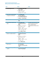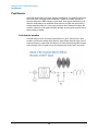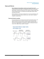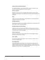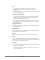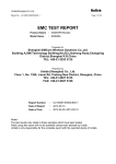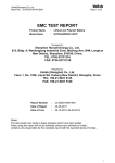
1
Agilent X-Series
Signal Analyzer
This manual provides documentation
for the following analyzers:
PXA Signal Analyzer N9030A
MXA Signal Analyzer N9020A
EXA Signal Analyzer N9010A
CXA Signal Analyzer N9000A
MXE EMI Receiver N9038A
EMC Measurement
Application Measurement
Guide
Agilent Technologies
Notices
© Agilent Technologies, Inc. 2011
Manual Part Number
No part of this manual may be
reproduced in any form or by any
means (including electronic storage
and retrieval or translation into a
foreign language) without prior
agreement and written consent from
Agilent Technologies, Inc. as
governed by United States and
international copyright laws.
N6141-90002
Trademark
Acknowledgements
Microsoft® is a U.S. registered
trademark of Microsoft Corporation.
Windows® and MS Windows® are
U.S. registered trademarks of
Microsoft Corporation.
Adobe Acrobat® and Reader® are
U.S. registered trademarks of Adobe
Systems Incorporated.
Java™ is a U.S. trademark of Sun
Microsystems, Inc.
MATLAB® is a U.S. registered
trademark of Math Works, Inc.
Norton Ghost™ is a U.S. trademark
of Symantec Corporation.
Wikipedia® is a registered
trademark of the Wikimedia
Foundation.
Supersedes: November 2010
Print Date
April 2011
Printed in USA
Agilent Technologies Inc.
1400 Fountaingrove Parkway
Santa Rosa, CA 95403
Warranty
The material contained in this
document is provided “as is,” and is
subject to being changed, without
notice, in future editions. Further, to
the maximum extent permitted by
applicable law, Agilent disclaims all
warranties, either express or
implied, with regard to this manual
and any information contained
herein, including but not limited to
the implied warranties of
merchantability and fitness for a
particular purpose. Agilent shall not
be liable for errors or for incidental
or consequential damages in
connection with the furnishing, use,
or performance of this document or
of any information contained herein.
Should Agilent and the user have a
separate written agreement with
warranty terms covering the material
in this document that conflict with
these terms, the warranty terms in
the separate agreement shall
control.
Technology Licenses
The hardware and/or software
described in this document are
furnished under a license and may
be used or copied only in accordance
with the terms of such license.
Restricted Rights Legend
If software is for use in the
performance of a U.S. Government
prime contract or subcontract,
Software is delivered and licensed
as “Commercial computer software”
as defined in DFAR 252.227-7014
(June 1995), or as a “commercial
item” as defined in FAR 2.101(a) or
as “Restricted computer software”
as defined in FAR 52.227-19 (June
1987) or any equivalent agency
regulation or contract clause. Use,
duplication or disclosure of Software
is subject to Agilent Technologies’
standard commercial license terms,
and non-DOD Departments and
Agencies of the U.S. Government
will receive no greater than
Restricted Rights as defined in FAR
52.227-19(c)(1-2) (June 1987). U.S.
Government users will receive no
greater than Limited Rights as
defined in FAR 52.227-14 (June
1987) or DFAR 252.227-7015 (b)(2)
(November 1995), as applicable in
any technical data.
Safety Notices
CAUTION
A CAUTION notice denotes a hazard.
It calls attention to an operating
procedure, practice, or the like that,
if not correctly performed or adhered
to, could result in damage to the
product or loss of important data. Do
not proceed beyond a CAUTION
notice until the indicated conditions
are fully understood and met.
WARNING
A WARNING notice denotes a
hazard. It calls attention to an
operating procedure, practice, or the
like that, if not correctly performed
or adhered to, could result in
personal injury or death. Do not
proceed beyond a WARNING notice
until the indicated conditions are
fully understood and met.
Warranty
This Agilent technologies instrument product is warranted against defects in material and workmanship for a
period of one year from the date of shipment. During the warranty period, Agilent Technologies will, at its
option, either repair or replace products that prove to be defective.
For warranty service or repair, this product must be returned to a service facility designated by Agilent
Technologies. Buyer shall prepay shipping charges to Agilent Technologies, and Agilent Technologies shall
pay shipping charges to return the product to Buyer. For products returned to Agilent Technologies from
another country, Buyer shall pay all shipping charges, duties, and taxes.
Where to Find the Latest Information
Documentation is updated periodically. For the latest information about these products, including instrument
software upgrades, application information, and product information, browse to one of the following URLs,
according to the name of your product:
http://www.agilent.com/find/pxa
http://www.agilent.com/find/mxa
http://www.agilent.com/find/exa
http://www.agilent.com/find/cxa
To receive the latest updates by email, subscribe to Agilent Email Updates at the following URL:
http://www.agilent.com/find/emailupdates
Information on preventing analyzer damage can be found at:
http://www.agilent.com/find/tips
3
4
Contents
Table of Contents
1 EMC Measurements
The Role of Precompliance in the Product Development Cycle
2 Conducted Emissions Measurements
Making Conducted Emission Measurements
10
3 Radiated Emissions Measurements
Making Radiated Emission Measurements
18
Appendix A Line Impedance Stabilization Networks (LISN)
LISN Operation
26
Types of LISNs
27
Appendix B Antenna Factors
Field Strength Units
30
Appendix C Basic Electrical Relationships
Appendix D Detectors Used in EMI Measurements
Peak Detector
36
Quasi-peak Detector
Average Detector
37
38
Glossary of Acronyms and Definitions
39
5
8
Contents
6
EMC Measurements
1
EMC Measurements
The EMC measurement application enables you to perform precompliance conducted
and radiated emissions tests to both commercial and MIL-STD requirements. It
provides better sensitivity, accuracy and reduces test margins, across the X-Series
signal analyzers, so you can make more precise measurement. The wide range of
features enables you to:
•
Set up frequency ranges, gains, bandwidths and dwell time
•
Scan a frequency range and display the results in log or linear format, search for
signals, measure the peak, quasi-peak and average values of the signal and place
the results in a table
•
Use the Signal List feature to mark and delete unwanted signals, leaving only those
of interest
•
Identify signals that fail the regulatory agency limit
7
EMC Measurements
The Role of Precompliance in the Product Development Cycle
The Role of Precompliance in the Product Development Cycle
To ensure successful electromagnetic interference (EMI) compliance testing,
precompliance testing has been added to the development cycle. In precompliance
testing, the electromagnetic compatibility (EMC) performance is evaluated from design
through production units.
It is important to have a strategy that will help you test for potential EMI problems
throughout the product development cycle. It is also important to have equipment and
processes in place that will allow you to observe how close you are to compliance at
any given time in the development cycle. This reduces the time and cost associated
with final compliance testing.
8
Conducted Emissions Measurements
2
Conducted Emissions
Measurements
Conducted emissions testing focuses on emissions that are conducted along a power
line that are generated by the device under test (DUT). The transducer that is typically
used to couple the emissions of the power line to the signal analyzer is a line
impedance stabilization network (LISN).
The regulatory limits specify the maximum DUT emission energy, usually in dBμV,
detected by the LISN. The test range for these measurements is typically 150 kHz to 30
MHz, though some limits may start as low as 9 kHz, depending on the regulation.
9
Conducted Emissions Measurements
Making Conducted Emission Measurements
Making Conducted Emission Measurements
Before connecting a signal to the analyzer, make sure the analyzer can safely accept
the signal level provided. The signal level limits are marked next to the RF Input
connectors on the front panel.
CAUTION
See the AMPTD Y Scale menu for details on setting internal attenuation to prevent
overloading the analyzer.
To prevent the signal analyzer input from possible damage that could be caused by
high level transient signals that could be produced by the LISN, it is recommended that
an 11947A Transient Limiter be used whenever conducted emissions testing is done
with the use of a LISN.
CAUTION
Setting up and making an ambient measurement
This section demonstrates how to set up and perform conducted emission tests in the
150 kHz to 30 MHz range.
NOTE
Determine which regulatory requirements you will be testing to prior to starting the
following procedure.
Step
Action
Notes
1 Test Set Up
a. Connect device under test
(DUT), LISN, and Limiter to
the signal analyzer as
shown below:
Ensure that the power cord
between the DUT and the LISN is
as short as possible. The power
cord can become an antenna if
allowed to be longer than
necessary.
10
Conducted Emissions Measurements
Making Conducted Emission Measurements
Step
Action
Notes
2 Turn on the signal analyzer.
a. Press the front-panel power
key.
3 Select the EMC mode.
a. Press Mode, EMI Receiver.
4 Open the scan table and
select the desired range
a. Press Meas Setup, Scan
Table, Range 2, Range to
On.
Deselect any other range that has
a green check.
5 Load Quasi-peak limit line
a. Press Recall, Data, Limit
Lines 1, Open.
The limit line will be turned on
after loading, If no data exists for
Trace 1, the Limit Line will not
display.
b. Select My Documents,
EMC limits and
Ampcor, Open,
Limits, Open, Files
of type.lim,
c. Scroll to EN 55022,
Class A Cond,
Quasi-peak.lim,
Open.
11
Conducted Emissions Measurements
Making Conducted Emission Measurements
Step
Action
Notes
6 Load Average limit line
a. Press Recall, Data, Limit
Lines 2, Open.
b. Scroll to EN 55022,
Class A Cond,
Average.lim, Open
7 Change EMI Average detector
to compare to Limit Line 2
a. Press Meas Setup,
Detectors (Measure)
b. Select Detector, Detector 3
c. Limit for Δ, Limit 2, Enter
8 Show limit lines.
a. Press Sweep Control, Start,
Stop.
9 Load correction factors for the
LISN
a. Press Recall, Data,
Amplitude Correction 1,
Open
b. Select My Documents,
EMC limits and
Ampcor, Open,
Ampcor, Open, Ampcor
Files of type.ant
c. Select LISN-10A, Open.
10 Add correction factors for the
limitor in correction factor 2
a. Press Recall, Data,
Amplitude Correction 2,
Open.
b. Select My Documents,
EMC limits and
Ampcor, Open,
Ampcor, Open, Files
of type.oth
c. Select 11947A, Open.
11 Insure that the correction
factors are on
a. Press Input/Output, More 1
of 2, Corrections,
Correction 1, On, Correction
2, On.
12 Insure that the input is DC
coupled
a. Press Input/Output, RF
Input, RF Coupling DC.
12
This places the corrections for the
LISN in Amplitude Correction 1.
These correction factors
compensate for the losses of the
LISN.
Conducted Emissions Measurements
Making Conducted Emission Measurements
Step
Action
Notes
13 Update the scan
a. Press Sweep/Control,
Start.
View the ambient emissions (with
the DUT off). If emissions above
the limit are noted, the power cord
between the LISN and the DUT
may be acting as an antenna.
Shorten the power cord to reduce
the response to ambient signals.
13
Conducted Emissions Measurements
Making Conducted Emission Measurements
Running Frequency Scan
Step
Action
Notes
1 Turn on the DUT and scan
a. Turn the DUT on.
Signals above the limit are
designated in red.
b. Press Meas Setup, Scan Sequence,
Scan Only, Sweep/Control, Start.
2 Stop the scan
a. Press Sweep/Control, Stop
14
This step will not be
necessary if the
measurement has completed
the number of scans set or
the desired time.
Conducted Emissions Measurements
Making Conducted Emission Measurements
Adding signals to the signal list
Step
Action
Notes
1 Clear any existing signal
list
a. Press Meas Setup, Signal List,
Delete Signals, Delete All
2 Switch to scan and search
a. Press Meas Setup, Scan Sequence,
Search Only
3 Set the search criteria to
peak criteria and limits
a. Press Meas Setup, More 1 of 2,
Limits, Search Criteria, Peak
Criteria and Limits
4 Add signals to the Signal
List
a. Press Sweep/Control, Start
15
Conducted Emissions Measurements
Making Conducted Emission Measurements
Measuring the Quasi-peak and average values of the signals
Step
Action
Notes
1 Perform a Re-measure on
all signals in the list
a. Press Meas Setup, Scan
Sequence, (Re)measure,
(Re)measure, All Signals,
Sweep/Control, Start.
2 Review the measurement
results
The delta to Limit Line values
should all be negative. If some
of the measurements are
positive, there is a problem
with conducted emissions
from the DUT.
Measurement tip
If the signals you are looking at are in the lower frequency range of the conducted
band, 2 MHz or lower, you can reduce the stop frequency to get a closer look. Note
that there are fewer points to view. You can add more data points using the scan table.
The default setting in the scan table is two data points per BW or 4.5 kHz per point. To
get more data points, change the points per bandwidth to 2.25 or 1.125 to give four or
eight points per BW.
16
Radiated Emissions Measurements
3
Radiated Emissions
Measurements
Radiated emissions measurements are not as strainghforward as conducted emissions
measurements. There is the added complexity of the ambient environment, which
could interfere with measuring the emissions from a device under test (DUT).
17
Radiated Emissions Measurements
Making Radiated Emission Measurements
Making Radiated Emission Measurements
Before connecting a signal to the analyzer, make sure the analyzer can safely accept
the signal level provided. The signal level limits are marked next to the RF Input
connectors on the front panel.
CAUTION
See the AMPTD Y Scale menu for details on setting internal attenuation to prevent
overloading the analyzer.
Setting up and making an ambient measurement
This section demonstrates how to set up and perform radiated emission tests in the 30
to 300 MHz range.
NOTE
Determine which regulatory requirements you will be testing to prior to starting the
following procedure.
Even if you only have access to a small shielded enclosure, you can still make valuable
measurement of your device. Emission signals found in the small chamber can save
you time later on in an open area test site by providing information about the
emissions of interest.
Step
Action
Notes
1 Test Set Up
a. Arrange the antenna, DUT
and signal analyzer as
shown below:
Separate the antenna and the device under
test (DUT) as specified by the regulatory
agency requirements. If space is limited, the
antenna can be moved closer to the DUT
and you can edit the limits to reflect the
new position. For example, if the antenna is
moved from 10 meters to 3 meters, the
amplitude must be adjusted by 10.45 dB. It
is important that the antenna is not placed
in the near field of the radiating device.
18
Radiated Emissions Measurements
Making Radiated Emission Measurements
Step
Action
Notes
2 Turn on the signal
analyzer.
a. Press the front-panel power
key.
3 Select the EMC mode.
a. Press Mode, EMI receiver.
4 Open the scan table
and select the desired
range
a. Press Meas Setup, Scan
Table, Range 3 to On.
5 Set the attenuation and
internal amplifier
a. Press Meas Setup, Scan
Table, More 1 of 3,
Attenuation, 0, dB, Internal
Preamp, Low Band.
19
Deselect any other range that has a green
check.
Radiated Emissions Measurements
Making Radiated Emission Measurements
Step
Action
Notes
6 Load limit lines
a. Press Recall, Data, Limit
Lines 1, Open.
b. Select My Documents,
EMC limits and
Ampcor, Open,
Limits, Open, Files
of type .lim, Open
c. Scroll to EN 55022,
Class A Rad (10m),
Open.
7 Load correction factors
for the biconical
antenna
a. Press Recall, Data,
Amplitude Corrections 1,
Open
b. Select My Documents,
EMC limits and
Ampcor, Open,
Ampcor, Open,
Ampcor Files of
type .ant
c. Select Biconical (30 MHz
to 300 MHz), Open.
8 Turn limits and
corrections on.
a. Press Sweep Control, Start,
Stop.
20
Radiated Emissions Measurements
Making Radiated Emission Measurements
Running Frequency Scan
Step
Action
Notes
1 Clear any existing
signal list
a. Press Meas Setup, Signal
List, Delete Signals,
Delete All
2 Turn on the DUT and
start frequency scan
a. Turn the DUT on.
b. Press Meas Setup, Scan
Sequence, Scan Only
c. Press Sweep/Control,
Start.
3 Stop the scan
a. Press Sweep/Control,
Stop
21
Radiated Emissions Measurements
Making Radiated Emission Measurements
Adding signals to the list
Step
Action
Notes
1 Set the search criteria
to peak criteria and
limits
a. Press Meas Setup, More 1 of 2,
Limits, Search Criteria, Peak
Criteria and Limits
2 Switch to search
a. Press Meas Setup, Scan
Sequence, Search Only
3 Add signals to the
Signal List
a. Press Sweep/Control, Start
22
This places the ambient signals in
the Signal List.
Radiated Emissions Measurements
Making Radiated Emission Measurements
Measuring the Quasi-peak and average values of the signals
Step
Action
Notes
1 Measure remaining
signals
a. Press Meas Setup, Scan
Sequence, (Re)measure,
(Re)measure All Signals.
b. Press Sweep/Control, Start
2 Review the
measurement results
23
Radiated Emissions Measurements
Making Radiated Emission Measurements
24
Line Impedance Stabilization Networks (LISN)
A: Line Impedance Stabilization
Networks (LISN)
A line impedance stabilization network serves three purposes:
1. The LISN isolates the power mains from the device under test. the power supplied
to the DUT must be as clean a possible. Any noise on the line will be coupled to the
X-Series signal analyzer and interpreted as noise generated by the DUT
2. The LISN isolates any noise generated by the EUT from being coupled to the power
mains. Excess noise on the power mains can cause interference with the proper
operation of other devices on the line.
3. The signals generated by the DUT are coupled to the X-Series analyzer using a
high-pass filter, which is part of the LISN. Signals that are in the pass band of the
high-pass filter see a 50-Ω load, which is the input to the X-Series signal analyzer
25
Line Impedance Stabilization Networks (LISN)
LISN Operation
LISN Operation
The following graphic shows a typical LISN circuit diagram for one side of the line
relative to earth ground. The chart represents the impedance of the DUT port versus
frequency.
The 1 μF in combination with the 50 μH inductor is the filter that isolates the mains
from the EUT. The 50 μH inductor isolates the noise generated by the EUT from the
mains. The 0.1 μF couples the noise generated by the EUT to the X-Series signal
analyzer or receiver. At frequencies above 150 kHz, the EUT signals are presented with
a 50Ω impedance.
26
Line Impedance Stabilization Networks (LISN)
Types of LISNs
Types of LISNs
The most common type of LISN is the V-LISN. It measures the unsymmetric voltage
between line and ground. This is done for both the hot and the neutral lines or for a
three phase circuit in a “Y” configuration, between each line and ground. There are
other specialized types of LISNs. A delta LISN measures the line-to-line or symmetric
emissions voltage. The T-LISN, sometimes used for telecommunications equipment,
measures the asymmetric voltage, which is the potential difference between the
midpoint potential between two lines and ground.
Transient Limiter Operation
The purpose of the limiter is to protect the input of the EMC analyzer from large
transients when connected to a LISN. Switching DUT power on or off can cause large
spikes generated in the LISN.
The Agilent 11947A transient limiter incorporates a limiter, high-pass filter, and an
attenuator. It can withstand 10 kW for 10 μsec and has a frequency range of 9 kHz to
200 MHz. The high-pass filter reduces the line frequencies coupled to the EMC
analyzer.
27
Line Impedance Stabilization Networks (LISN)
Types of LISNs
28
Antenna Factors
B: Antenna Factors
29
Antenna Factors
Field Strength Units
Field Strength Units
Radiated EMI emissions measurements measure the electric field. The field strength is
calibrated in dBμV/m. Field strength in dBμV/m is derived from the following:
Pt = total power radiated from an isotropic radiator
PD = the power density at a distance r from the isotropic radiator (far field)
PD = Pt /4πr2
R = 120mΩ
PD = E2/R
E2/R = Pt /4πr2
E = (Pt x 30)1/2 /r (V/m)
Far field1 is considered to be >λ/2π
Antenna factors
The definition of antenna factors is the ratio of the electric field in volts per meter
present at the plane of the antenna versus the voltage out of the antenna connector.
NOTE
Antenna factors are not the same as antenna gain.
1. Far Field is the minimum distance from a radiator where the field becomes a planar wave.
30
Antenna Factors
Field Strength Units
Types of antennas used for commercial radiated measurements
There are three types of antennas used for commercial radiated emissions
measurements:
•
Biconical antenna: 30 MHz to 300 MHz
•
Log periodic antenna: 200 MHz to 1 GHz (the biconical and log periodic overlap
frequency)
•
Broadband antenna: 30 MHz to 1 GHz (larger format than the biconical or log
periodic antennas)
31
Antenna Factors
Field Strength Units
32
Basic Electrical Relationships
C: Basic Electrical Relationships
The decibel is used extensively in electromagnetic measurements. It is the log of the
ratio of two amplitudes. The amplitudes are in power, voltage, amps, electric field units
and magnetic field units.
decibel = dB = 10 log (P2/P1)
Data is sometimes expressed in volts or field strength units. In this case, replace
P with V2/R.
If the impedances are equal, the equation becomes:
dB = 20 log (V2/V1)
A unit of measure used in EMI measurements is dBμV or dBìA. The relationship of
dBμV and dBm is as follows:
dBμV = 107 + PdBm
This is true for an impedance of 50Ω.
Wave length (l) is determined using the following relationship:
λ = 3x10⁸/f (Hz) or λ = 300/f (MHz)
33
Basic Electrical Relationships
34
Detectors Used in EMI Measurements
D: Detectors Used in EMI
Measurements
35
Detectors Used in EMI Measurements
Peak Detector
Peak Detector
Initial EMI measurements are made using the peak detector. This mode is much faster
than quasi-peak, or average modes of detection. Signals are normally displayed on
spectrum analyzers or EMC analyzers in peak mode. Since signals measured in peak
detection mode always have amplitude values equal to or higher than quasi-peak or
average detection modes, it is a very easy process to take a sweep and compare the
results to a limit line. If all signals fall below the limit, then the product passes and no
further testing is needed.
Peak detector operation
The EMC analyzer has an envelope or peak detector in the IF chain that has a time
constant, such that the voltage at the detector output follows the peak value of the IF
signal at all times. In other words, the detector can follow the fastest possible changes
in the envelope of the IF signal, but not the instantaneous value of the IF sine wave.
36
Detectors Used in EMI Measurements
Quasi-peak Detector
Quasi-peak Detector
Most radiated and conducted limits are based on quasi-peak detection mode.
Quasi-peak detectors weigh signals according to their repetition rate, which is a way of
measuring their annoyance factor. As the repetition rate increases, the quasi-peak
detector does not have time to discharge as much, resulting in a higher voltage output.
(See the following graphic.) For continuous wave (CW) signals, the peak and the
quasi-peak are the same.
Quasi-peak detectors always give a reading less than or equal to peak detectors, but
quasi-peak measurements are much slower by two or three orders of magnitude
compared to a peak detector.
Quasi-peak detector operation
The quasi-peak detector has a charge rate much faster than the discharge rate. The
higher the repetition rate of the signal, the higher the output of the quasi-peak
detector. The quasi-peak detector also responds to different amplitude signals in a
linear fashion. High-amplitude, low-repetition-rate signals could produce the same
output as low-amplitude, high-repetition-rate signals.
37
Detectors Used in EMI Measurements
Average Detector
Average Detector
The average detector is required for some conducted emissions tests in conjunction
with using the quasi-peak detector. Also, radiated emissions measurements above 1
GHz are performed using average detection. The average detector output is always
less than or equal to peak detection.
Average detector operation
Average detection is similar in many respects to peak detection. The following graphic
shows a signal that has just passed through the IF and is about to be detected. The
output of the envelope detector is the modulation envelope. Peak detection occurs
when the post detection bandwidth is wider than the resolution bandwidth. For
average detection to take place, the peak detected signal must pass through a filter
whose bandwidth is much less than the resolution bandwidth. The filter averages the
higher frequency components, such as noise at the output of the envelope detector.
38
Glossary of Acronyms and
Definitions
39
Ambient level
1. The values of radiated and conducted signal and noise existing at a specified test
location and time when the test sample is not activated
2. Those levels of radiated and conducted signal and noise existing at a specified test
location and time when the test sample is inoperative. Atmospherics, interference
from other sources, and circuit noise, or other interference generated within the
measuring set compose the ambient level.
Amplitude modulation
1. In a signal transmission system, the process, or the result of the process, where
the amplitude of one electrical quantity is varied in accordance with some selected
characteristic of a second quantity, which need not be electrical in nature.
2. The process by which the amplitude of a carrier wave is varied following a specified
law.
Anechoic chamber
A shielded room which is lined with radio absorbing material to reduce reflections from
all internal surfaces. Fully lined anechoic chambers have such material on all internal
surfaces, wall, ceiling and floor. Its also called a “fully anechoic chamber.” A
semianechoic chamber is a shielded room which has absorbing material on all
surfaces except the floor.
Antenna (aerial)
1. A means for radiated or receiving radio waves. A transducer which either emits
radio frequency power into space from a signal source or intercepts an arriving
electromagnetic field, converting it into an electrical signal.
2. A transducer which either emits radio frequency power into space from a signal
source or intercepts an arriving electromagnetic field, converting it into an
electrical signal.
Antenna factor
The factor which, when properly applied to the voltage at the input terminals of
themeasuring instrument, yields the electric field strength in volts per meter and a
magnetic field strength in amperes per meter.
Antenna induced voltage
The voltage which is measured or calculated to exist across the open circuited
antenna terminals.
40
Antenna terminal conducted interference
Any undesired voltage or current generated within a receiver, transmitter, or their
associated equipment appearing at the antenna terminals.
Auxiliary equipment
Equipment not under test that is nevertheless indispensable for setting up all the
functions and assessing the correct performance of the EUT during its exposure to the
disturbance.
Balun
A balun is an antenna balancing device, which facilitates use of coaxial feeds with
symmetrical antennae such as a dipole.
Broadband emissions
Broadband is the definition for an interference amplitude when several spectral lines a
within the RFI receivers specified bandwidth.
Broadband interference (measurements)
A disturbance that has a spectral energy distribution sufficiently broad, so that the
response of the measuring receiver in use does not vary significantly when tuned over
a specified number of receiver bandwidths.
Conducted interference
Interference resulting from conducted radio noise or unwanted signals entering a
transducer (receiver) by direct coupling.
Cross-coupling
The coupling of a signal from on channel, circuit, or conductor to another, where it
becomes an undesired signal.
Decoupling network
A decoupling network is an electrical circuit for preventing test signals which are
applied to the EUT from affecting other devices, equipment, or systems that are not
under test. IEC 801-6 states that the coupling and decoupling network systems can be
integrated in one box or they can be separate networks.
41
Dipole
1. An antenna consisting of a straight conductor usually not more than a
half-wavelength long, divided at its electrical center for connection to a
transmission line.
2. Any one of a class of antennas producing a radiation pattern approximating that of
an elementary electric dipole.
Electromagnetic compatibility (EMC)
1. The capability of electronic equipment of systems to be operated within defined
margins of safety in the intended operating environment at designed levels of
efficiency without degradation due to interference.
2. EMC is the ability of equipment to function satisfactorily in its electromagnetic
environment without introducing intolerable disturbances into that environment or
into other equipment.
Electromagnetic interference
Electromagnetic interference is the impairment of a wanted electromagnetic signal by
an electromagnetic disturbance
Electromagnetic wave
The radiant energy produced by the oscillation of an electric charge characterized by
oscillation of the electric and magnetic fields.
Emission
Electromagnetic energy propagated from a source by radiation or conduction.
Far Field
The region where the power flux density from an antenna approximately obeys an
inverse squares law of the distance. For a dipole this corresponds to distances greater
than l/2 where l is the wave length of the radiation.
Ground plane
1. A conducting surface or plate used as a common reference point for circuit returns
and electric or signal potentials.
2. A metal sheet or plate used as a common reference point for circuit returns and
electrical or signal potentials.
42
Immunity
1. The property of a receiver or any other equipment or system enabling it to reject a
radio disturbance.
2. The ability of electronic equipment to withstand radiated electromagnetic fields
without producing undesirable responses.
Intermodulation
Mixing of two or more signals in a nonlinear element, producing signals at frequencies
equal to the sums and differences of integral multiples of the original signals.
Isotropic
Isotropic means having properties of equal values in all directions.
Mono pol
An antenna consisting of a straight conductor, usually not more than one-quarter wave
length long, mounted immediately above, and normal to, a ground plane. It is
connected to a transmission line at its base and behaves, with its image, like a dipole.
Narrowband emissions
That which has its principal spectral energy lying within the bandpass of the
measuring receiver in use.
Open area
A site for radiated electromagnetic interference measurements which is open flat
terrain at a distance far enough away from buildings, electric lines, fences, trees,
underground cables, and pipe lines so that effects due to such are negligible. This site
should have a sufficiently low level of ambient interference to permit testing to the
required limits.
Polarization
A term used to describe the orientation of the field vector of a radiated field.
Radiated interference
Radio interference resulting from radiated noise of unwanted signals. Compare radio
frequency interference below.
Radiation
The emission of energy in the form of electromagnetic waves.
Radio frequency interference
43
RFI is the high frequency interference with radio reception. This occurs when
undesired electromagnetic oscillations find entrance to the high frequency input of a
receiver or antenna system.
RFI sources
Sources are equipment and systems as well as their components which can cause RFI.
Shielded enclosure
A screened or solid metal housing designed expressly for the purpose of isolating the
internal from the external electromagnetic environment. The purpose is to prevent
outside ambient electromagnetic fields from causing performance degradation and to
prevent emissions from causing interference to outside activities.
Stripline
Parallel plate transmission line to generate an electromagnetic field for testing
purposes.
Susceptibility
Susceptibility is the characteristic of electronic equipment that permits undesirable
responses when subjected to electromagnetic energy.
44
45