1
synaesthesia
// karl petre
swarthmore college - department of engineering
engineering 90 [ engineering design ]
2007
introduction /
context and purpose
Within the music-oriented realm of intelligent lighting, there exists a fundamental
and unforgivable shortcoming. Current lighting devices run pre-programmed
patterns, which progress based on vibration pulses that the lighting units detect.
Actuation of these lighting devices is limited to the delayed vibration information
that is gathered by these sensors. Such a configuration – although quickly
conceivable – is only crudely effective. Due to this fact, these lighting systems do
not have the ability to truly respond to music, and much possibility for the
enhancement of the listener’s experience is overlooked.
The purpose of completing this project is to create more advanced systems, using a
perspective that is different from that of the common design. Rather than relying
on delayed vibration content, these devices have more suitable inputs: they are
hard-wired to the audio signal. Instead of running through pre-programmed visual
progressions, their processing schemes use genre-specific decomposition
algorithms to analyze what has been played. Consequently, they detect and
appropriately respond to motion within the music.
tempo /
real-time estimation
Software for producing a real-time tempo estimate of an audio signal. Pages 3
through 31.
revision /
algorithm correction
Revisions to the Tempo algorithm. Pages 32 though 47.
pulser /
intelligent strobe system
A marketable user-controlled intelligent strobe system. Pages 48 through 71.
dmxer /
interactive dmx mixer
A prototype mixer for controlling a DMX lighting apparatus. Pages 72 though 98.
tempo /
real-time estimation
karl petre / swarthmore college
abstract /
concept and result
This portion of the development is concerned with providing an algorithm for
returning high-precision estimates of the tempo of incoming audio streams. While
possible improvements were recognized, the selected algorithm proved highly
successful in accomplishing its task.
introduction /
context and purpose
The first stage of achieving the Synaesthesia vision is to correctly break an
incoming audio stream into beat-based segments. By analyzing each segment and
comparing multiple segments, the overall structure of the incoming audio signal
may be extracted. This portion of the project focuses on a method for estimating
the tempo of any music in the electronica genre.
This report presents a brief discussion of the hardware and software environments
to be used, and provides a thorough technical description of the tempo extraction
algorithm. The algorithm is then simulated, and its performance is quantified. A
real-time implementation of the algorithm is presented, along with a comparison of
its performance to the simulated results.
hardware environment /
overview
// hardware
The Tempo project makes use of existing hardware, rather than existing as a standalone unit. It is being coded on a Linux platform, and uses an M-Audio Delta1010LT
soundcard to provide the necessary input and output interfaces. A relatively large
number of inputs are needed, because the final system will take three stereo
channels of data – the master output from a DJ’s mixer, as well as the two unmixed
cue channels.
// use of existing hardware
In terms of product marketability, it is highly advantageous for the system to
operate on hardware that the consumer already possesses. This would help to
reduce the system’s market price, and would allow the consumer to easily
incorporate the system onto their pre-existing lighting infrastructure.
software environment /
overview
// the jack audio connection kit
introduction
JACK is a low-latency audio server, written for POSIX conformant operating
systems such as Linux. It can connect several client applications to an audio device,
and allow them to share audio with each other. Clients can run as separate
processes like normal applications, or within the JACK server as plug-ins. JACK was
designed from the ground up for professional audio work, and its design focuses on
two key areas: synchronous execution of all clients, and low latency operation [1].
The Tempo software package is being written using the JACK API. Use of the highlevel abstraction layer provided by the API allows all hardware to be managed
trivially. It is desired that the Tempo engine produce an output with a latency of no
more than is perceivable by the listener; this is fully supported by the JACK
environment.
1.
For more information see http://www.jackaudio.org.
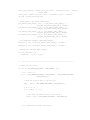
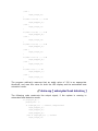
jack client structure
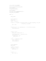
The structure of JACK client is fairly simple, and can be summarized as follows:
#include <jack/jack.h>
...
jack_port_t *input_port;
...
int process (jack_nframes_t nframes, void *arg) {
jack_default_audio_sample_t *in = (jack_default_audio_sample_t *)
jack_port_get_buffer(input_port, nframes);
...
}
void jack_shutdown (void *arg) {
...
exit (1);
}
int main (int argc, char *argv[]) {
char *client_name = 0;
jack_client_t *client;
const char **ports;
...
jack_set_process_callback (client, process, 0);
jack_on_shutdown (client, jack_shutdown, 0);
input_port = jack_port_register(client, "master_in_left",
JACK_DEFAULT_AUDIO_TYPE, JackPortIsInput, 0);
if (jack_activate (client)) {
fprintf(stderr, "cannot activate client");
return 1;
}
...
for (;;)
}
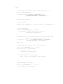
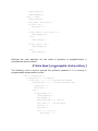
The main function is responsible for setting up the client, and is then put to sleep.
The JACK server calls the process function whenever it needs to send or read data
to or from the client’s ports. The jack_shutdown function is called in the event that
the server is shut down, or if the server stops calling the client.
// fftw
introduction
FFTW is a C subroutine library for computing the discrete Fourier transform (DFT) in
one or more dimensions, of arbitrary input size, and of both real and complex data
[2]. It is the Fourier transform library of choice in most cases, and is used
exclusively by this project for such computations.
The PCM-coded audio signals to be processed are read from the buffer of the
soundcard. At a sampling rate of 44 kHz, there is more than enough data for the
desired processing. The typical buffer size is 1024 data points, although this and
several other relevant values are configurable in the JACK interface.
2.
For more information see http://www.fftw.org.
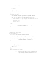
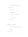
referencing the fftw library
Using the FFTW library is fairly straightforward. To compute a one-dimensional DFT
of size N, the following code structure is used:
#include <fftw3.h>
...
{
fftw_complex *in, *out;
fftw_plan p;
...
in = (fftw_complex*) fftw_malloc(sizeof(fftw_complex) * N);
out = (fftw_complex*) fftw_malloc(sizeof(fftw_complex) * N);
p = fftw_plan_dft_1d(N, in, out, FFTW_FORWARD, FFTW_ESTIMATE);
...
fftw_execute(p);
...
fftw_destroy_plan(p);
fftw_free(in);
fftw_free(out);
}
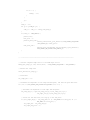
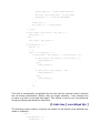
In this case, all of the input data is real, so the following FFTW plan call is used:
fftw_plan fftw_plan_dft_r2c_1d(int n, double *in, fftw_complex *out, unsigned
flags);
Moreover, since JACK presents all of its data as float precision numbers, all
instances of fftw are replaced by fftwf in the Tempo code.
tempo and beat estimation /
overview
// introduction
Tempo estimation is necessary for most autonomous music processing. Likewise, it
is essential for the Tempo engine to precisely estimate the tempo of the audio
streams it will manage. Music of the trance and house genres is quit percussive;
due to this fact, the tempo tracking algorithm employed by Tempo may overlook
several steps that are usually involved in this task. Moreover, the tempo of the
audio stream should not change throughout its duration. It is assumed that the
tempo lies between 110 and 150 BPM. These assumptions create an advantage in
terms of computational time, which is highly desirable due to the real-time nature
of this project.
There are three stages of the beat tracking algorithm. In the first, the major events
in the music are extracted. Second, the periodicity of the audio stream is examined,
and the tempo is found. Finally, the estimated tempo is applied to search the audio
stream for the instances in time where the beats occur.
// algorithm description
event detection
The key to tempo extraction lies in correctly locating the significant events within
the temporal waveform. By comparing the onset times of these occurrences, the
periodicity of the music may be established. As is commonly used, a frequency
domain approach is taken in order to process the input audio waveform.
The signal is first converted to a decimated version of its short-time Fourier
transform (STFT). This is accomplished by taking fixed-length segments of the
incoming audio stream, and compiling a chronological sequence of their Fourier
transforms. In most cases, each adjacent segment overlaps by some set amount;
no such overlapping was employed here. The transform is given by
N −1
X ( f , m ) = ∑ w(n )x(n + m )e − j 2πfn
n =0
where x(n ) is the audio signal, w(n ) is the analysis window of N samples, m is the
frame index, and f is the frequency. For this application w(n )
rectangular window.
is simply a
One of the more robust approaches to event detection involves using the STFT to
find the spectral energy flux of the waveform. The spectral energy flux E ( f , k ) of
the STFT is defined by [3] as
E ( f , k ) = ∑ h(m − k )G ( f , m )
m
where h(m ) approximates a differentiator filter, and G ( f , m ) is obtained by passing
X ( f , m ) through a low-pass filter and a non-linear compression. This transform
seeks to approximate the derivative of the signal frequency content with respect to
time; significant events emerge as peaks in the resulting transform.
Simplifications occur, once again due to the percussive nature of the particular
audio signals to be examined. The Tempo algorithm lets G ( f , m ) = X ( f , m ) , thus
utilizing the full spectrum of the audio signal. One of the main implications of using
a differentiator filter is to destroy the zero-frequency components of the signal.
While beneficial, this step proved unnecessary in this application. Tempo uses a
rather crude approximation of the derivative of the signal frequency for event
detection, which is given by
E S ( f , k ) = ∑∑ X ( f , m ) − X ( f , m − 1)
m
f
The resulting transform is half-rectified and summed for each m to produce a
temporal waveform v(k ) , where v(k ) exhibits quick magnitude spikes at the onset
of significant events in the music. As can be expected, however, the waveform v(k )
contains a great amount of spurious noise that obscures the desired information.
As suggested by [3], a median filter is applied to the function v(k ) to remove the
false peaks. The value of the median threshold is found from a moving window of
2i + 1 samples. Letting g k = {v k −i , …, v k ,… , v k +i }, it is given by
T (k ) = C ⋅ median( g k )
where C is a scaling factor that raises each cutoff value. The resulting function p (k )
is given by
⎧v(k ) v(k ) > T (k )
p(k ) = ⎨
otherwise
⎩ 0
The function p (k ) is the event detection function used by the Tempo system.
3.
Alonso M., David B. and Richard G., “Tempo and Beat Estimation of Musical Signals,” proceedings
of ISMIR, 2004.
tempo estimation
In many applications, the spectral sum or spectral product of p (k ) is computed [4].
Both of these techniques assume that the power spectrum of an audio signal
consists of harmonics of its fundamental frequency. If this is the case, summing or
multiplying recursive temporal compressions of the data leads to datasets of
strongly reinforced fundamental frequencies.
By using stringent parameter settings in the steps leading to p (k ) , estimating the
periodicity of p (k ) becomes trivial. In this particular case, the FFT of p (k ) yields
precision tempo estimates of the audio waveforms.
4.
Simon D., “Onset Detection Revisited,” proceedings of the 9th Int. Conference on Digital Audio
Effects (DAFx-06), Montreal, Canada, September 2006.
beat location estimation
To find the beat, an artificial pulse-train is created, with pulses that are spaced in
accordance with the extracted tempo (as suggested in [3], referencing others). The
pulses are given a finite width, to account for inaccuracies in their placement due to
the resolution of the tempo-estimation algorithm. The pulse-train is then crosscorrelated with the event detection function p (k ) ; a beat is located whenever the
cross-correlation is above a particular threshold.
// simulation with controlled input signals
Before the tempo detection algorithm was applied to any actual waveforms, it was
applied to a test set. This set of audio samples each consisted of bass drum kicks,
located on each downbeat in any given measure. The tempos of the test waveforms
ranged from 125 to 145 BPM, with an interval of 1 BPM.
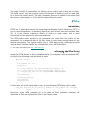
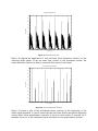
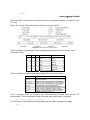
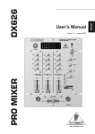
The following discussion uses the test waveform with a tempo of 135 BPM.
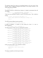
event detection
Figure 1 shows the time waveform of the 135-BPM audio signal over a time period
of about 3 seconds.
Time Waveform
0.5
0.4
0.3
0.2
Amplitude
0.1
0
-0.1
-0.2
-0.3
-0.4
-0.5
0
0.5
1
1.5
2
Time (sec)
Figure 1. Time waveform of a 135-BPM test signal.
2.5
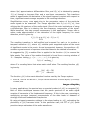
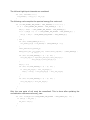
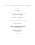
Figure 2 shows a conversion of this waveform to its STFT.
STFT (with 2.9025 ms windows)
1.2
Frequency (kHz)
1
0.8
0.6
0.4
0.2
0
0
0.5
1
1.5
Time (sec)
2
2.5
Figure 2. STFT off the 135-BPM waveform.
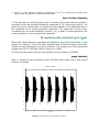
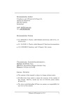
Figure 3 shows the spectral energy flux of this data.
Spectral Energy Flux (with 2.9025 ms windows)
1.2
Frequency (kHz)
1
0.8
0.6
0.4
0.2
0
0.5
1
1.5
Time (sec)
2
Figure 3. Spectral energy flux by frequency bin.
2.5
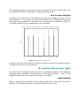
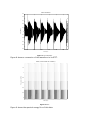
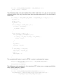
Figure 4 shows the summed spectral energy flux function, along with the event
detection function.
Spectral Energy Flux
1
Magnitude
0.8
0.6
0.4
0.2
0
0
0.5
1
1.5
Time (sec)
2
2.5
2
2.5
Event Detection Function
1
Magnitude
0.8
0.6
0.4
0.2
0
0
0.5
1
1.5
Time (sec)
Figure 4. Spectral energy flux, and the event detection function.
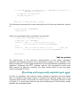
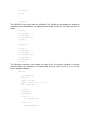
tempo estimation
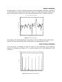
In order to detect the tempo at an acceptable resolution, the signal is evaluated
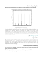
over a longer period of time. Figure 5 shows the Fourier transform of the event
detection function for a 95-second sampling of the 135-BPM test waveform.
FFT, tempo found at 135.0072 BPM
0
-20
Normalized magnitude (dB)
-40
-60
-80
-100
-120
-140
-160
1.7
1.8
1.9
2
2.1
Frequency (Hz)
2.2
2.3
Figure 5. FFT of the event detection function.
2.4
2.5
The estimated tempo is accurate to within 0.006 percent of the actual tempo, and
the nearest spike has an attenuation of approximately 40 dB.
beat location estimation
Initializing the comb filter at an arbitrary starting time causes it to seek out the
next maximum. In this case, the comb filter searches the 135-BPM test waveform
starting at approximately 3.5 seconds from its beginning. As illustrated in Figure 6,
it correctly latches on to the beginning of the next beat.
Peak Detection Function and Comb Filter, Cross-correlation of 7.5537 at 3.9909 sec
1
0.9
0.8
Magnitude
0.7
0.6
0.5
0.4
0.3
0.2
0.1
0
4
4.5
5
T ime (sec)
5.5
6
6.5
Figure 6. Application of the comb filter.
However, since the event detection function is able to extract the onsets of each of
its beats, this result is to be expected.
// simulation with real input signals
The next level of analysis involves the use of real audio waveforms. The following
discussion uses a waveform representation of the track DJ Tiësto – Close To You
(Magik Muzik Remix), which also has a tempo of 135 BPM.
event detection
Figure 7 shows the time waveform of the audio signal over a time period of about 3
seconds. This sample begins at an arbitrarily chosen point in time.
Time Waveform
0.5
0.4
0.3
0.2
Amplitude
0.1
0
-0.1
-0.2
-0.3
-0.4
-0.5
615.5
616
616.5
617
T ime (sec)
617.5
618
Figure 7. The waveform.
Figure 8 shows a conversion of this waveform to its STFT.
STFT (with 2.9025 ms windows)
1.2
Frequency (kHz)
1
0.8
0.6
0.4
0.2
0
615.5
616
616.5
617
T ime (sec)
Figure 8. STFT.
Figure 9 shows the spectral energy flux of this data.
617.5
618
Spectral Energy Flux (with 2.9025 ms windows)
1.2
Frequency (kHz)
1
0.8
0.6
0.4
0.2
0
615.5
616
616.5
617
T ime (sec)
617.5
618
Figure 9. Spectral energy flux by frequency bin.
Figure 10 shows the summed spectral energy flux function, along with the event
detection function.
Spectral Energy Flux
1
Magnitude
0.8
0.6
0.4
0.2
0
615.5
616
616.5
617
T ime (sec)
617.5
618
617.5
618
Event Detection Function
1
Magnitude
0.8
0.6
0.4
0.2
0
615.5
616
616.5
617
T ime (sec)
Figure 10. Spectral energy flux and the event detection function.
tempo estimation
As done before, in order to detect the tempo at an acceptable resolution, the signal
is evaluated over a longer period of time. Figure 11 shows the Fourier transform of
the event detection function for a 95-second sampling of the 135-BPM waveform.
FFT, tempo found at 135.0072 BPM
0
Normalized magnitude (dB)
-20
-40
-60
-80
-100
-120
1.7
1.8
1.9
2
2.1
Frequency (Hz)
2.2
2.3
2.4
2.5
Figure 11. Tempo estimation.
Once again, the estimated tempo is accurate to within 0.006 percent of the actual
tempo, and the nearest spike has an attenuation of approximately 40 dB.
beat location estimation
The comb filter is initialized to start its search at the beginning of the sampling
window. As illustrated in Figure 12, it correctly latches on to the beginning of the
next beat.
Peak Detection Function and Comb Filter, Cross-correlation of 5.4018 at 615.5581 sec
1
0.9
0.8
0.7
Magnitude
0.6
0.5
0.4
0.3
0.2
0.1
0
615.5
616
616.5
617
T ime (sec)
617.5
Figure 12. Application of the comb filter.
618
// simulation with real input signals [ revisited ]
It can be seen that the audio segment addressed in section 5.4 closely resembles
that of section 5.3, and it is therefore not surprising that the algorithm may
correctly extract the tempo of the waveform.
The following discussion once again uses a waveform representation of the track DJ
Tiësto – Close To You (Magik Muzik Remix). This time, however, event detection
function is unable to detect each beat.
event detection
Figure 13 shows the time waveform of the audio signal.
Time Waveform
1
0.8
0.6
0.4
Amplitude
0.2
0
-0.2
-0.4
-0.6
-0.8
-1
1490
1500
1510
1520
1530
1540
T ime (sec)
1550
1560
1570
1580
Figure 13. Waveform.
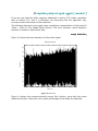
Figure 14 shows the summed spectral energy flux function, along with the event
detection function. Note that only a small percentage of the beats are detected.
Spectral Energy Flux
1
Magnitude
0.8
0.6
0.4
0.2
0
1490
1500
1510
1520
1530
1540
T ime (sec)
1550
1560
1570
1580
1560
1570
1580
Event Detection Function
1
Magnitude
0.8
0.6
0.4
0.2
0
1490
1500
1510
1520
1530
1540
T ime (sec)
1550
Figure 14. Spectral energy flux and the event detection function.
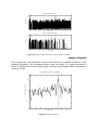
tempo estimation
Even though the event detection function has failed for a substantial portion of the
sampled waveform, the estimated tempo does not falter. It is again accurate to
within 0.006 percent of the actual tempo, and the nearest spike has an attenuation
of about 35 dB.
FFT, tempo found at 135.0072 BPM
0
Normalized magnitude (dB)
-20
-40
-60
-80
-100
-120
1.7
1.8
1.9
2
2.1
Frequency (Hz)
2.2
Figure 15. Tempo estimation.
2.3
2.4
2.5
beat location estimation
Moreover, the comb filter correctly latches on to the beginning of the next beat.
Peak Detection Function and Comb Filter, Cross-correlation of 4.8241 at 1486.17 sec
1
0.9
0.8
0.7
Magnitude
0.6
0.5
0.4
0.3
0.2
0.1
0
1486.5
1487
1487.5
T ime (sec)
1488
1488.5
1489
Figure 16. Application of the comb filter.
It is true that this particular comb filter would fail if the window started at, for
example, 1570 seconds. However, increasing the length of the comb filter
compensates for this issue. If the comb is able to latch on to a beat that occurs
before the break in onset detections, then the beat times occurring during the lapse
may be interpolated – at a negligible loss in accuracy of each timestamp due to the
precision tempo estimate.
// real-time system
introduction
The operation of the real-time system mirrors the operation of the simulations as
closely as possible, and is successful in its task almost to the same extent as the
simulations are. It is highly compact in its structure, which accounts for its
complexity. The code used may leave some room for improvement, due to my
inexperience with the language.
headers and variable declarations
The majority of the variables used by the Tempo client are declared as globals, due
to the structure of its operation.
The following variables mirror parameters which may be set in JACK:
#define JACK_FRAMES_PER_BUFFER 1024
#define JACK_SAMPLES_PER_SEC 44100
The standard number of frames (samples) per JACK buffer cycle is 1024. A
combination of these particular settings provides a maximum latency of 46.4 ms
between the time that the sample is passed to the audio card and passed to the
JACK client. It would be beneficial to have these numbers read directly from JACK;
however a method for doing so has not been established at the present.
The following variables are internal to this client, and define the size – and thus
resolution – of both the STFT stage and the tempo-estimating FFT stage. The first
of these refers to the sample size of each STFT input; the setting used provides a
resolution of less than 3 ms per timestamp. The second value defines the number
of STFT windows to be processed and sent to the tempo-estimating FFT.
#define STFT_BUFFERS 128
#define STFT_WINDOW_N 128
The tempo estimation is limited by upper and lower bounds, these are also
predefined:
#define MIN_TEMPO 100
#define MAX_TEMPO 150
The parameters for the median filter are defined to be the same as those used in
simulation. The window extends for MF_N values to either side of the indexed data
point.
#define MF_N 10
#define C 5
The following values define the JACK ports:
jack_port_t *input_port_m_l;
jack_port_t *input_port_m_r;
jack_port_t *input_port_c1_l;
jack_port_t *input_port_c1_r;
jack_port_t *input_port_c2_l;
jack_port_t *input_port_c2_r;
jack_port_t *output_port_m_l;
jack_port_t *output_port_m_r;
The following variables define the raw audio input arrays:
float *raw_l;
float *raw_r;
float *raw_mixed;
The following variables are used for the STFT, and the calculation of the spectral
energy flux:
float *fft_window_in;
fftwf_complex *fft_window_out;
fftwf_plan fft_window_p;
double *stft_old_mag;
fftwf_complex *stft_new;
double *stft_new_mag;
float stft_old_sum;
float stft_new_sum;
float sef_max;
float *sef;
The following variables are used for the tempo-estimating FFT. The input to the FFT
is the event detection function edf.
float *edf;
float *fft_tempo_in;
fftwf_complex *fft_tempo_out;
fftwf_plan fft_tempo_p;
double *fft_tempo_mag;
This variable is used as a counter, for determining how full the tempo-estimation
FFT input is. This value is sent to the terminal.
unsigned int edf_fill_count;
The following variables are for timing, so that events may be time stamped as
necessary.
struct timeval tv;
struct timezone tz;
float start_time;
float current_time;
The tempo is also defined as a global. The value stored in freq_inc is the frequency
increment between any two adjacent tempo-estimation FFT outputs.
double tempo;
double freq_inc;
Knowledge of these variables is essential for understanding the operation of the
code.
the main function
The main function is called at the start of client execution. It is responsible for
configuring the client so that it may run solely on its JACK process callback. After
this function has completed the setup, it is put to sleep.
The first thing that is done is to record the time at which this program was
initialized, so that this value may be referenced if desired:
gettimeofday(&tv, &tz);
start_time = (double)(tv.tv_sec % 1000) + ((double)tv.tv_usec) / 1000000.0;
The only argument that may be passed in (at present) is the name for the client. If
no value is passed in, the client name is defaulted to synaesthesia.
if (argc < 2) {
client_name = (char *) malloc (9 * sizeof (char));
strcpy (client_name, "synaesthesia");
} else {
client_name = (char *) malloc (9 * sizeof (char));
strcpy (client_name, argv[1]);
}
Next, all the required memory space is allocated. FFTW requires the use of
fftwf_malloc.
raw_l = (float *) (sizeof(float) * JACK_FRAMES_PER_BUFFER);
raw_r = (float *) fftwf_malloc(sizeof(float) * JACK_FRAMES_PER_BUFFER);
raw_mixed = (float *) fftwf_malloc(sizeof(float) * JACK_FRAMES_PER_BUFFER);
fft_window_in = (float *) fftwf_malloc(sizeof(float) * STFT_WINDOW_N);
fft_window_out = (fftwf_complex *) fftwf_malloc(sizeof(fftwf_complex) *
((STFT_WINDOW_N / 2) + 1));
fft_window_p = fftwf_plan_dft_r2c_1d(STFT_WINDOW_N, fft_window_in,
fft_window_out, FFTW_ESTIMATE);
//fft_window_mag = (double *) malloc(sizeof(float) * ((STFT_WINDOW_N / 2) +
1));
edf = (float *) fftwf_malloc(sizeof(float) * JACK_FRAMES_PER_BUFFER *
STFT_BUFFERS);
fft_tempo_in = (float *) fftwf_malloc(sizeof(float) * JACK_FRAMES_PER_BUFFER *
STFT_BUFFERS);
fft_tempo_out = (fftwf_complex *) fftwf_malloc(sizeof(fftwf_complex) *
((JACK_FRAMES_PER_BUFFER * STFT_BUFFERS / 2) + 1));
fft_tempo_p = fftwf_plan_dft_r2c_1d(JACK_FRAMES_PER_BUFFER*STFT_BUFFERS,
fft_tempo_in, fft_tempo_out, FFTW_ESTIMATE);
fft_tempo_mag = (double *) malloc(sizeof(double) * ((JACK_FRAMES_PER_BUFFER *
STFT_BUFFERS / 2) + 1));
stft_old_mag = (double *) fftwf_malloc(sizeof(double) * ((STFT_WINDOW_N / 2) +
1));
stft_new_mag = (double *) fftwf_malloc(sizeof(double) * ((STFT_WINDOW_N / 2) +
1));
stft_new = (fftwf_complex *) fftwf_malloc(sizeof(fftwf_complex) *
((STFT_WINDOW_N / 2) + 1));
sef = (float *) fftwf_malloc(sizeof(float) * ((MF_N * 2) + 1 +
(JACK_FRAMES_PER_BUFFER / STFT_WINDOW_N)));
The values in the event detection function are initialized to zero:
for (i=0; i<JACK_FRAMES_PER_BUFFER * STFT_BUFFERS-1; i++) {
edf[i] = 0.0;
}
The spectral energy flux values are normalized based on the max value of this
function, which is updated throughout the duration of the client’s execution. This
value must also be initialized:
sef_max = 0.0;
The tempo increment is defined here, because it is based on parameters that will
not change:
freq_inc = 1.0 / ((JACK_FRAMES_PER_BUFFER * STFT_BUFFERS) * (1.0 /
(JACK_SAMPLES_PER_SEC / STFT_WINDOW_N)));
Tempo may now attempt to become a client of the JACK server. This is called as
follows:
if ((client = jack_client_new (client_name)) == 0) {
fprintf (stderr, "Check that the JACK server is running...\n");
return 1;
}
The JACK process callback must be specified:
jack_set_process_callback (client, process, 0);
If JACK is shutdown, or decides to stop calling the client, it is sent to
jack_shutdown():
jack_on_shutdown (client, jack_shutdown, 0);
The JACK input and output ports are established as follows:
input_port_m_l = jack_port_register(client, "master_in_left",
JACK_DEFAULT_AUDIO_TYPE, JackPortIsInput, 0);
input_port_m_r = jack_port_register(client, "master_in_right",
JACK_DEFAULT_AUDIO_TYPE, JackPortIsInput, 0);
input_port_c1_l = jack_port_register(client, "cue_1_left",
JACK_DEFAULT_AUDIO_TYPE, JackPortIsInput, 0);
input_port_c1_r = jack_port_register(client, "cue_1_right",
JACK_DEFAULT_AUDIO_TYPE, JackPortIsInput, 0);
input_port_c2_l = jack_port_register(client, "cue_2_left",
JACK_DEFAULT_AUDIO_TYPE, JackPortIsInput, 0);
input_port_c2_r = jack_port_register(client, "cue_2_right",
JACK_DEFAULT_AUDIO_TYPE, JackPortIsInput, 0);
output_port_m_l = jack_port_register(client, "master_out_left",
JACK_DEFAULT_AUDIO_TYPE, JackPortIsOutput, 0);
output_port_m_r = jack_port_register(client, "master_out_right",
JACK_DEFAULT_AUDIO_TYPE, JackPortIsOutput, 0);
Finally, the client is able to roll, and JACK is notified:
if (jack_activate (client)) {
fprintf(stderr, "cannot activate client");
return 1;
}
The setup is complete, and main goes to sleep.
for (;;)
the jack process callback function
The JACK process callback is called whenever there is a buffer ready to be imported
from or exported to JACK.
Only a minimal number of variable declarations must be made during each callback.
These are all temporary, and will be lost after the completion of the callback.
int i;
int j;
int k;
double fft_tempo_max;
int fft_tempo_max_place;
double tempo_freq;
double mf_max;
double mf_thresh;
int mf_count;
Each buffer cycle is time stamped:
gettimeofday(&tv, &tz);
current_time = (double)(tv.tv_sec % 1000) + ((double)tv.tv_usec) / 1000000.0;
The following lines define where to get and put the JACK buffers:
jack_default_audio_sample_t *out_m_l = (jack_default_audio_sample_t *)
jack_port_get_buffer(output_port_m_l, nframes);
jack_default_audio_sample_t *out_m_r = (jack_default_audio_sample_t *)
jack_port_get_buffer(output_port_m_r, nframes);
jack_default_audio_sample_t *in_m_l = (jack_default_audio_sample_t *)
jack_port_get_buffer(input_port_m_l, nframes);
jack_default_audio_sample_t *in_m_r = (jack_default_audio_sample_t *)
jack_port_get_buffer(input_port_m_r, nframes);
jack_default_audio_sample_t *in_c1_l = (jack_default_audio_sample_t *)
jack_port_get_buffer(input_port_c1_l, nframes);
jack_default_audio_sample_t *in_c1_r = (jack_default_audio_sample_t *)
jack_port_get_buffer(input_port_c1_r, nframes);
jack_default_audio_sample_t *in_c2_l = (jack_default_audio_sample_t *)
jack_port_get_buffer(input_port_c2_l, nframes);
jack_default_audio_sample_t *in_c2_r = (jack_default_audio_sample_t *)
jack_port_get_buffer(input_port_c2_r, nframes);
Passing JACK input streams to JACK output streams is accomplished as follows.
Tempo passes its master inputs to its master outputs.
memcpy(out_m_l, in_m_l, sizeof(jack_default_audio_sample_t) * nframes);
memcpy(out_m_r, in_m_r, sizeof(jack_default_audio_sample_t) * nframes);
The JACK input buffers are copied:
memcpy(raw_l, in_m_l, sizeof(jack_default_audio_sample_t) * nframes);
memcpy(raw_r, in_m_r, sizeof(jack_default_audio_sample_t) * nframes);
The left and right input channels are combined:
for (i=0; i<nframes; i++) {
raw_mixed[i] = raw_l[i] + raw_r[i];
}
The following code compiles the spectral energy flux vector sef.
for (i=(JACK_FRAMES_PER_BUFFER * STFT_BUFFERS)-1; i>=0; i--) {
if (i > ((JACK_FRAMES_PER_BUFFER / STFT_WINDOW_N) - 1)) {
edf[i] = edf[i - (JACK_FRAMES_PER_BUFFER / STFT_WINDOW_N)];
if (i < ((MF_N * 2) + 1 + (JACK_FRAMES_PER_BUFFER / STFT_WINDOW_N))) {
sef[i] = sef[i - (JACK_FRAMES_PER_BUFFER / STFT_WINDOW_N)];
}
} else {
for (k=0; k<STFT_WINDOW_N; k++) {
fft_window_in[k] = raw_mixed[k + (STFT_WINDOW_N * i)];
}
fftwf_execute(fft_window_p);
memcpy(stft_new, fft_window_out, sizeof(fftwf_complex) * ((STFT_WINDOW_N /
2) + 1));
for (k=0; k<((STFT_WINDOW_N / 2) - 1); k++) {
stft_new_mag[k] = sqrt(stft_new[k][0]*stft_new[k][0] +
stft_new[k][1]*stft_new[k][1]);
}
sef[i] = 0.0;
for (k=0; k<((STFT_WINDOW_N / 2) - 1); k++) {
if (stft_new_mag[k] > stft_old_mag[k]) {
sef[i] = sef[i] + stft_new_mag[k] - stft_old_mag[k];
}
}
for (k=0; k<((STFT_WINDOW_N / 2) - 1); k++) {
stft_old_mag[k] = stft_new_mag[k];
}
}
}
Only the new parts of sef must be normalized. This is done after updating the
normalization reference value sef_max.
for (i=0; i<((MF_N*2)+1+(JACK_FRAMES_PER_BUFFER / STFT_WINDOW_N)); i++) {
if (sef[i] > sef_max) {
sef_max = sef[i];
}
}
for (i=0; i<(JACK_FRAMES_PER_BUFFER / STFT_WINDOW_N); i++) {
sef[i] = sef[i] / sef_max;
}
The following code runs the median filter. Note that there is a lag of one process
callback (about 46.4 ms) from the time that new data enters sef to the time that it
enters edf.
for (i=(MF_N + (JACK_FRAMES_PER_BUFFER / STFT_WINDOW_N)); i>(MF_N-1); i--) {
mf_count = 1;
mf_max = 0.0;
mf_thresh = 0.0;
for (j=(i-MF_N); j<(i+MF_N+1); j++) {
if (sef[j] > mf_thresh) {
mf_thresh = sef[j];
}
}
while (mf_count < (MF_N + 2)) {
for (j=(i-MF_N); j<(i+MF_N+1); j++) {
if ((sef[j] > mf_max) && (sef[j] < mf_thresh)) {
mf_max = sef[j];
}
}
mf_count++;
mf_thresh = mf_max;
}
if (sef[i-MF_N] > C*mf_max) {
edf[i-MF_N] = sef[i-MF_N];
} else {
edf[i-MF_N] = 0;
}
}
The compiled edf vector is sent to FFTW in order to estimate the tempo:
memcpy(fft_tempo_in, edf, sizeof(float) * JACK_FRAMES_PER_BUFFER *
STFT_BUFFERS);
fftwf_execute(fft_tempo_p);
The following code searches for the maximum FFT value, over a range specified by
MIN_TEMPO and MAX_TEMPO:
fft_tempo_max = 0.0;
for (i=0; i<(JACK_FRAMES_PER_BUFFER*STFT_BUFFERS/2)+1; i++) {
fft_tempo_mag[i] = sqrt(fft_tempo_out[i][0]*fft_tempo_out[i][0] +
fft_tempo_out[i][1]*fft_tempo_out[i][1]);
if ((fft_tempo_mag[i] > fft_tempo_max) && (i > MIN_TEMPO/60.0/freq_inc) && (i
< MAX_TEMPO/60.0/freq_inc)) {
fft_tempo_max = fft_tempo_mag[i];
fft_tempo_max_place = i;
}
}
tempo_freq = fft_tempo_max_place * freq_inc;
The following increments the counter that tells how full the event detection function
is:
if (edf_fill_count < STFT_BUFFERS) {
edf_fill_count++;
}
Finally, the estimated tempo is printed to the terminal:
if (tempo_freq*60 > MAX_TEMPO) tempo_freq = 0;
if (tempo_freq * 60.0 > MAX_TEMPO) {
printf("\r
tempo: ---.--- bpm (fft buffer at %1.1f%%)
100.0*(float)edf_fill_count/(float)STFT_BUFFERS);
",
} else {
printf("\r
tempo: %7.3f bpm (fft buffer at %1.1f%%)
", tempo_freq *
60.0, 100.0*(float)edf_fill_count/(float)STFT_BUFFERS);
}
fflush(stdout);
limits to precision
The performance of the real-time implementation of the tempo estimation
algorithm was limited primarily by the processing capacity of the computer. The
tempo-locating FFT is the largest contributor to the computational complexity of the
algorithm. Increasing the STFT windows used for this computation would most
likely improve its accuracy; however, the value chosen above is near the upper
limit of achievable FFT size.
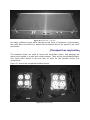
// real-time performance with controlled input signals
As done in simulation, the real-time tempo estimation algorithm was first tested
with a controlled input signal. Figure 17 presents the spectral energy flux of the
incoming audio stream, as found by the Tempo engine. Comparing this plot of that
of Figure 4, it can be seen that the real-time performance of this function closely
matches the simulated results.
Spectral Energy Flux
1
0.9
0.8
0.7
Magnitude
0.6
0.5
0.4
0.3
0.2
0.1
0
0
100
200
300
400
500
600
ST FT window
700
800
900
1000
Figure 17. Spectral energy flux.
Figure 18 depicts an application of the real-time event detection function to the
incoming audio signal. It can be seen that, similar to the simulated results, the
event detection function is able to recognize the onset of each beat.
Event Detection Function
1
0.9
0.8
0.7
Magnitude
0.6
0.5
0.4
0.3
0.2
0.1
0
0
100
200
300
400
500
600
ST FT Sample
700
800
900
1000
Figure 18. The event detection function.
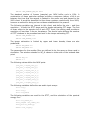
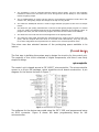
Figure 19 shows a plot of the estimated tempo, starting at the beginning of the
audio signal playback. It can be seen that the real-time tempo estimation algorithm
comes within three quantization intervals of the true value within 2 seconds. By 5
seconds, the error in the estimated value has fallen to one quantization interval.
Tempo Found at 134.794922 BPM
140
135
Tempo found (BPM)
130
125
120
115
110
105
100
0
5
10
15
T ime (sec)
Figure 19. Tempo estimation.
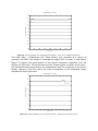
// real-time performance with real input signals
The performance of the Tempo tempo estimation algorithm was tested for a
number of waveforms, varying over the range of attainable tempos.
In order to further compare the real-time implementation of the algorithm to the
simulated results, it was tested using track DJ Tiësto – Close To You (Magik Muzik
Remix). Figure 20 presents a plot of the estimated tempo over the duration of the
track. It takes the algorithm approximately 25 seconds to come within a reasonable
estimate of the tempo. The tempo is estimated to be less than its true value (135
BPM) by one quantization interval for the majority of the track’s length (from 50 to
275 seconds). It then drops by another quantization level, most likely due to a
failure in the event detection function over that interval. Finally, towards the end of
the track, the tempo raises to a value that is one quantization level above where it
should be.
Found Tempo vs. Time
136
135
134
Found tempo (BPM)
133
132
131
130
129
128
127
126
0
50
100
150
200
T ime (sec)
250
300
350
400
Figure 20. Tempo estimation over the duration of DJ Tiësto – Close To You (Magik Muzik Remix).
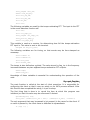
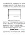
The track Skin – Faithfulness (DJ Tiësto Remix) was recorded at a tempo of
precisely 140 BPM; this tempo is towards the upper limit of music in this genre.
Figure 21 depicts the performance of the tempo estimation algorithm over the
duration of this track. The performance of the Tempo engine is similar in this case –
the estimated tempo stays within one quantization level for a majority of the track’s
length. However, this time there are more fluctuations in the estimated tempo
towards the end of the track.
Found Tempo vs. Time
142
140
Found tempo (BPM)
138
136
134
132
130
128
0
50
100
150
200
250
300
T ime (sec)
350
400
450
500
550
Figure 21. Tempo estimation over the duration of Skin – Faithfulness (DJ Tiësto Remix).
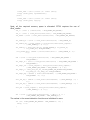
The track Bounce Back by Armin van Buuren (featuring DJ Remy and Roland
Klinkenberg) was recorded at a tempo of precisely 130 BPM. This is one of the
slower tempos seen by the genre. Figure 22 presents the performance of the tempo
estimation algorithm over the duration of this track. It can be seen that in this
case, Tempo is quite effective in estimating the tempo over the duration of the
track. The algorithm comes within one quantization level of the true tempo after
only 10 seconds, and stays within two quantization levels for the remainder of the
track.
Found Tempo vs. Time
133.5
133
132.5
Found tempo (BPM)
132
131.5
131
130.5
130
129.5
129
128.5
0
50
100
150
200
250
300
T ime (sec)
350
400
450
500
Figure 22. Tempo detection over the duration of Armin van
Buuren (feat. DJ Remy and Roland Klinkenberg) – Bounce Back.
One of the ways in which to improve the estimation algorithm would be to use a
Kalman filter to control the value of the estimated tempo. The Kalman filter is a
recursive estimator for the state of a dynamic system. Kalman filters are especially
useful when the data is incomplete or noisy, which is the case in this particular
situation. When applied to the above waveforms, the Kalman filter would eliminate
the presence of unwanted fluctuations, and would capitalize on the fact that the
tempo estimation should not change during the duration of any given track.
It may also be noted that for each of these waveforms (and the controlled
waveform) the estimated tempo is slightly less than the true tempo. This fact could
be used in order to further refine the accuracy of the tempo estimation.
conclusions /
successes and shortcomings
Initially, this project was to be prepared as a stand-alone module, using a PCBmount computer. The time taken to set up the PCB computer – and realize its
failure to operate as needed – hindered the amount of progress that could be made
during this semester. However, the work that was completed is a large step
towards the completion of the project as a whole.
This semester’s work familiarized me with a large variety of issues pertaining to
software development. Prior to beginning my project, I had little experience with
hardware management, programming in C, and the use of third-party coding
libraries. While much time was spent in coding the final product, I had to spend a
large portion of the semester preparing myself to code in the necessary
environment. This preparation is extremely valuable in reference to the work I will
do next semester, because now I am fully prepared to tackle the tasks I hope to
complete.
credit /
influences and recognitions
The following individuals were integral in the development of this project:
Bruce Maxwell, Professor
Erik Cheever, Professor
Paul Davis, Linux Audio Systems
revision /
algorithm correction
karl petre / swarthmore college
abstract /
overview and result
In revisiting the work done for the Tempo software, severe errors were found. This
portion of the project development addresses these errors, and provides corrected
software.
alterations /
quick summary
The main modification that was made to the Tempo source code was to reorient
each of its temporally-based vectors. Originally, each of these vectors was oriented
as follows, where t0 is the oldest time and tn is the most recent time:
x0
tn
x1
tn-1
x2
tn-2
x3
tn-3
x4
tn-4
x5
tn-5
x6
tn-6
x7
tn-7
x8
tn-8
...
...
xn-2
t2
xn-1
t1
xn
t0
This representation is counterintuitive, because a plot of the vector would be
reversed in the time domain.
The Tempo source code was rewritten, with the following vector orientation:
x0
t0
x1
t1
x2
t2
x3
t3
x4
t4
x5
t5
x6
t6
x7
t7
x8
t8
...
...
xn-2
tn-2
xn-1
tn-1
xn
tn
In addition to the vector reorientation, the code was completely overhauled to
produce a much more finished and concise final program.
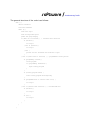
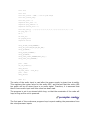
code /
complete documentation
The following is the complete revised source code for the real-time tempo
estimation algorithm.
#include <stdio.h>
#include <errno.h>
#include <unistd.h>
#include <stdlib.h>
#include <string.h>
#include <sys/types.h>
#include <sys/stat.h>
#include <fcntl.h>
#include <unistd.h>
#include <math.h>
#include <jack/jack.h>
#include <fftw3.h>
#include <sys/time.h>
#include <time.h>
#define JACK_FRAMES_PER_BUFFER 1024
#define JACK_SAMPLES_PER_SEC 44100
#define STFT_BUFFERS 128
#define STFT_WINDOW_N 128
#define MIN_TEMPO 100
#define MAX_TEMPO 150
#define MF_N 10 // Number to count on either side.
#define C 1.2 // No more than about 1.25
#define COMB_N 2000
#define COMB_WIDTH 3 // Half-1
#define COMB_THRESH 5 // About 9 beats per
#define RESET
0
#define BRIGHT
1
#define DIM
2
#define UNDERLINE
3
#define BLINK
4
#define REVERSE
7
#define HIDDEN
8
#define BLACK
0
#define RED
1
#define GREEN
2
#define YELLOW
3
#define BLUE
4
#define MAGENTA
5
#define CYAN
6
#define WHITE
7
// JACK variables.
jack_port_t *input_port_l;
jack_port_t *input_port_r;
jack_port_t *output_port_l;
jack_port_t *output_port_r;
// Raw audio input variables.
float *in_mixed;
float *inv_out;
// STFT variables for FFTW.
float *fft_window_in;
fftwf_complex *fft_window_out;
fftwf_plan fft_window_p;
double *stft_old_mag;
fftwf_complex *stft_new;
double *stft_new_mag;
float stft_old_sum;
float stft_new_sum;
float sef_max;
float *sef; // Spectral energy function.
// Tempo variables for FFTW.
float *edf; // Event detection function.
float *fft_tempo_in;
fftwf_complex *fft_tempo_out;
fftwf_plan fft_tempo_p;
double *fft_tempo_mag;
// Comb filter variables.
float *edf_mem;
float *comb;
short int windows_per_beat;
// For telling how full
unsigned int edf_fill_count;
// Timing variables
struct timeval tv;
struct timezone tz;
double start_time;
double current_time;
double run_time;
double new_tempo_time;
double const_tempo_time;
double buffer_cycle_duration;
// The tempo.
double tempo;
double freq_inc;
double prev_tempo;
double previous_beat_time;
double next_beat_time;
// ===============================================================================
void textcolor (int attr, int fg, int bg) {
char command[13];
sprintf(command, "%c[%d;%d;%dm", 0x1B, attr, fg + 30, bg + 40);
printf("%s", command);
}
// ===============================================================================
void move_cursor (int row, int col) {
printf("\033[%d;%dH", row, col);
}
// ===============================================================================
int process (jack_nframes_t nframes, void *arg) {
// Variable declarations.
int i;
int j;
int k;
int l;
double fft_tempo_max;
int fft_tempo_max_place;
double tempo_freq;
short int event_place;
float event_val;
short int event_bool;
short int beat_bool;
float comb_cc;
// Median filter variables.
double mf_max;
double mf_thresh;
int mf_count;
// Timestamp each buffer cycle.
gettimeofday(&tv, &tz);
buffer_cycle_duration = (double)(tv.tv_sec % 1000) + ((double)tv.tv_usec) / 1000000.0
- current_time;
current_time = (double)(tv.tv_sec % 1000) + ((double)tv.tv_usec) / 1000000.0;
run_time = current_time-start_time;
// Define where to get and put JACK buffers.
jack_default_audio_sample_t *out_l = (jack_default_audio_sample_t *)
jack_port_get_buffer(output_port_l, nframes);
jack_default_audio_sample_t *out_r = (jack_default_audio_sample_t *)
jack_port_get_buffer(output_port_r, nframes);
jack_default_audio_sample_t *in_l = (jack_default_audio_sample_t *)
jack_port_get_buffer(input_port_l, nframes);
jack_default_audio_sample_t *in_r = (jack_default_audio_sample_t *)
jack_port_get_buffer(input_port_r, nframes);
// Pass JACK input streams to JACK output streams.
memcpy(out_l, in_l, sizeof(jack_default_audio_sample_t) * nframes);
memcpy(out_r, in_r, sizeof(jack_default_audio_sample_t) * nframes);
// Mix the left and right input channels.
for (i=0; i<nframes; i++) {
in_mixed[i] = in_l[i] + in_r[i];
}
// ---------------------------------------------------------------------------
// Compile the sef[] vector.
for (i=0; i<(JACK_FRAMES_PER_BUFFER * STFT_BUFFERS); i++) {
// If i < total - 8...
if (i < ((JACK_FRAMES_PER_BUFFER * STFT_BUFFERS) - (JACK_FRAMES_PER_BUFFER /
STFT_WINDOW_N))) {
// Shift the values in edf[] to the left by 8.
edf[i] = edf[i + (JACK_FRAMES_PER_BUFFER / STFT_WINDOW_N)];
// If i < 29 - 8
if (i < ((MF_N * 2) + 1)) {
// Also shift the values in sef[] to the left by 8.
sef[i] = sef[i + (JACK_FRAMES_PER_BUFFER / STFT_WINDOW_N)];
}
// If i references the newest 8 data points...
} else {
// Take the FFT of each segment of data. i should range from 0 to 7...
for (k=0; k<STFT_WINDOW_N; k++) {
fft_window_in[k] = in_mixed[k + (STFT_WINDOW_N * (i ((JACK_FRAMES_PER_BUFFER * STFT_BUFFERS) (JACK_FRAMES_PER_BUFFER / STFT_WINDOW_N))))];
}
fftwf_execute(fft_window_p);
// Copy to stft_new[].
memcpy(stft_new, fft_window_out, sizeof(fftwf_complex) * ((STFT_WINDOW_N / 2)
+ 1));
// Find its magnitude.
for (k=0; k<((STFT_WINDOW_N / 2) - 1); k++) {
stft_new_mag[k] = sqrt(stft_new[k][0]*stft_new[k][0] +
stft_new[k][1]*stft_new[k][1]);
}
// Initialize sef[] place. The median filter is run on sef[]. sef[] ranges
from 0 to 28, initialize from 21 to 28.
l = ((MF_N * 2) + 1) + (i - ((JACK_FRAMES_PER_BUFFER * STFT_BUFFERS) (JACK_FRAMES_PER_BUFFER / STFT_WINDOW_N)));
sef[l] = 0.0;
// Compile sef[]. This runs from 21 to 28 (the new values).
//for (k=0; k<((STFT_WINDOW_N / 2) - 1); k++) {
for (k=0; k<8; k++) { // LPF @ 1050 Hz
if (k > 14 && k < 20) {
//printf("%f,", stft_new_mag[k]);
}
if (stft_new_mag[k] > stft_old_mag[k]) {
sef[l] = sef[l] + stft_new_mag[k] - stft_old_mag[k];
}
}
// Shift stft_new[] to stft_old[].
for (k=0; k<((STFT_WINDOW_N / 2) - 1); k++) {
stft_old_mag[k] = stft_new_mag[k];
}
}
}
// Update sef_max.
for (i=0; i<((MF_N*2)+1+(JACK_FRAMES_PER_BUFFER / STFT_WINDOW_N)); i++) {
if (sef[i] > sef_max) {
sef_max = sef[i];
}
}
// Normalize the new parts of sef[]. The new parts are 21 to 28.
for (i=((MF_N * 2) + 1); i <= ((MF_N*2)+1+(JACK_FRAMES_PER_BUFFER / STFT_WINDOW_N));
i++) {
sef[i] = sef[i] / sef_max;
//printf("%f\n", sef[i]);
}
// ---------------------------------------------------------------------------
// Assume that there is no beat in this buffer cycle (initialize).
beat_bool = 0;
event_bool = 0;
event_place = -1;
event_val = 0;
// Run the median filter, oldest to newest (10 to 17).
for (i=MF_N; i<(MF_N + (JACK_FRAMES_PER_BUFFER / STFT_WINDOW_N)); i++) {
// Initialize
mf_count = 1;
mf_max = 0.0;
mf_thresh = 0.0;
// Initialize mf_thresh (search from i-10 to i+10).
for (j=(i-MF_N); j<(i+MF_N+1); j++) {
if (sef[j] > mf_thresh) {
mf_thresh = sef[j];
}
}
// Count down 11 max values to find the middle one (aka while < 12).
while (mf_count < (MF_N + 2)) {
// Seach from i-10 to i+10.
for (j=(i-MF_N); j<(i+MF_N+1); j++) {
if ((sef[j] > mf_max) && (sef[j] < mf_thresh)) {
mf_max = sef[j];
}
}
mf_count++;
mf_thresh = mf_max;
//printf("%f,", mf_thresh);
}
printf("%f,%f\n", sef[i], C*mf_max);
if (sef[i] > C*mf_max) {
edf[(JACK_FRAMES_PER_BUFFER * STFT_BUFFERS)-(JACK_FRAMES_PER_BUFFER /
STFT_WINDOW_N)+i-MF_N] = sef[i];
event_bool = 1; // There is a beat detected in this buffer cycle.
if (sef[i] > event_val) { // Find the highest event (maybe search each, if
this isn't good enough?).
event_place = i-MF_N;
event_val = sef[i];
}
} else {
edf[(JACK_FRAMES_PER_BUFFER * STFT_BUFFERS)-(JACK_FRAMES_PER_BUFFER /
STFT_WINDOW_N)+i-MF_N] = 0;
}
}
// ---------------------------------------------------------------------------
// Shift edf_mem[], add new values.
for (i=0; i<COMB_N; i++) {
if (i < COMB_N-(JACK_FRAMES_PER_BUFFER/STFT_WINDOW_N)) {
edf_mem[i] = edf_mem[i+(JACK_FRAMES_PER_BUFFER/STFT_WINDOW_N)];
} else {
edf_mem[i] = edf[(i-(COMB_N-(JACK_FRAMES_PER_BUFFER/STFT_WINDOW_N))) +
(JACK_FRAMES_PER_BUFFER * STFT_BUFFERS)(JACK_FRAMES_PER_BUFFER / STFT_WINDOW_N)];
}
}
if (windows_per_beat > 0) {
for (j=COMB_N-1; j>=0; j--) {
comb[j] = 0.0;
}
j = 0;
while (j*windows_per_beat < COMB_N) {
for (k=COMB_N-j*windows_per_beat-((JACK_FRAMES_PER_BUFFER/STFT_WINDOW_N)event_place)+COMB_WIDTH; k>=COMB_N-j*windows_per_beat((JACK_FRAMES_PER_BUFFER/STFT_WINDOW_N)-event_place)COMB_WIDTH; k--) {
if (k >= 0) {
comb[k] = 1.0;
}
}
j++;
}
comb_cc = 0.0;
for (j=0; j<COMB_N; j++) {
comb_cc = comb_cc + comb[j]*edf_mem[j];
}
if (comb_cc > COMB_THRESH) {
printf("\n");
beat_bool = 1;
previous_beat_time =
current_time+(buffer_cycle_duration/(JACK_FRAMES_PER_BUFFER
/STFT_WINDOW_N))*event_place;
next_beat_time =
previous_beat_time+windows_per_beat*buffer_cycle_duration/(
JACK_FRAMES_PER_BUFFER/STFT_WINDOW_N);
}
}
// ---------------------------------------------------------------------------
// Send the compiled tempo vector to the FFTW input vector.
memcpy(fft_tempo_in, edf, sizeof(float) * JACK_FRAMES_PER_BUFFER * STFT_BUFFERS);
// Execute the tempo FFT.
fftwf_execute(fft_tempo_p);
// Initialize.
fft_tempo_max = 0.0;
// Determine the magnitude of each tempo FFT datapoint, and find the peak FFT value.
for (i=0; i<(JACK_FRAMES_PER_BUFFER*STFT_BUFFERS/2)+1; i++) {
// Determine the magnitude of each tempo FFT datapoint.
fft_tempo_mag[i] = sqrt(fft_tempo_out[i][0]*fft_tempo_out[i][0] +
fft_tempo_out[i][1]*fft_tempo_out[i][1]);
// Search for the max value, but only up to the 6th place.
if ((fft_tempo_mag[i] > fft_tempo_max) && (i > MIN_TEMPO/60.0/freq_inc) && (i <
MAX_TEMPO/60.0/freq_inc)) {
fft_tempo_max = fft_tempo_mag[i];
fft_tempo_max_place = i;
}
}
// Calculate the freqeuncy accociated with the max value.
tempo_freq = fft_tempo_max_place * freq_inc;
tempo = tempo_freq * 60;
// Check to see if the estimated tempo has changed.
if (tempo != prev_tempo) {
new_tempo_time = current_time;
windows_per_beat = JACK_SAMPLES_PER_SEC * 60.0 / STFT_WINDOW_N / tempo;
if (windows_per_beat > 0) {
for (j=COMB_N-1; j>=0; j--) {
comb[j] = 0.0;
}
j = 0;
while (j*windows_per_beat < COMB_N) {
for (k=COMB_N-j*windows_per_beat-((JACK_FRAMES_PER_BUFFER/STFT_WINDOW_N)event_place)+COMB_WIDTH; k>=COMB_N-j*windows_per_beat((JACK_FRAMES_PER_BUFFER/STFT_WINDOW_N)-event_place)COMB_WIDTH; k--) {
if (k >= 0) {
comb[k] = 1.0;
}
}
j++;
}
comb_cc = 0.0;
for (j=0; j<COMB_N; j++) {
comb_cc = comb_cc + comb[j]*edf_mem[j];
}
if (comb_cc > COMB_THRESH) {
beat_bool = 1;
previous_beat_time =
current_time+(buffer_cycle_duration/(JACK_FRAMES_PER_BUFFER
/STFT_WINDOW_N))*event_place;
next_beat_time =
previous_beat_time+windows_per_beat*buffer_cycle_duration/(
JACK_FRAMES_PER_BUFFER/STFT_WINDOW_N);
}
}
// -----------------------------------------------------------------------
/*printf("\n\n\n");
for (i=0; i<COMB_N; i++) {
printf("%f,%f\n", comb[i], edf_mem[i]);
}*/
} else {
const_tempo_time = floorf(current_time)-floorf(new_tempo_time);
}
if (edf_fill_count < STFT_BUFFERS) {
edf_fill_count++;
}
if (beat_bool == 0) { // If beat times were not already defined during the comb filter
code...
if (current_time + buffer_cycle_duration > next_beat_time) {
beat_bool = 1; // There is a beat during this buffer cycle.
previous_beat_time = next_beat_time;
next_beat_time =
previous_beat_time+windows_per_beat*buffer_cycle_duration/(
JACK_FRAMES_PER_BUFFER/STFT_WINDOW_N);
}
if (current_time < next_beat_time - (next_beat_time-previous_beat_time)/2) {
//beat_bool = 1;
}
}
if (tempo > MAX_TEMPO) tempo = 0;
// Print to the terminal.
printf("\033[2J");
move_cursor(2, 0);
textcolor(RESET, WHITE, BLACK);
printf("
Synaesthesia, Build 0.0\n");
textcolor(RESET, RED, BLACK);
printf("
Engine uptime: %1.0f seconds\n\n", run_time);
printf("
Estimated tempo: %1.1f BPM ", tempo);
if (const_tempo_time >= 2) {
printf("(constant for %1.0f seconds) ", const_tempo_time);
} else if (const_tempo_time >= 1) {
printf("(constant for 1 second) ");
}
if (100.0*(float)edf_fill_count/(float)STFT_BUFFERS < 100) {
printf("(FFT buffer at %1.1f%%) ",
100.0*(float)edf_fill_count/(float)STFT_BUFFERS);
}
printf("\n
Beat detection:");
if (event_bool) {
printf(" %c", 164);
} else printf("
");
if (beat_bool) {
printf(" %c", 164);
}
printf("\n\n
");
fflush(stdout);
prev_tempo = tempo;
return 0;
}
// ===============================================================================
void jack_shutdown (void *arg)
{
fftwf_destroy_plan(fft_window_p);
fftwf_free(fft_window_in);
fftwf_free(fft_window_out);
fftwf_destroy_plan(fft_tempo_p);
fftwf_free(fft_tempo_in);
fftwf_free(fft_tempo_out);
exit (1);
}
// ===============================================================================
int main (int argc, char *argv[])
{
char *client_name = 0;
jack_client_t *client;
const char **ports;
int i;
gettimeofday(&tv, &tz);
start_time = (double)(tv.tv_sec % 1000) + ((double)tv.tv_usec) / 1000000.0;
printf("\033[2J");
if (argc < 2) {
client_name = (char *) malloc (9 * sizeof (char));
strcpy (client_name, "synaesthesia");
} else {
client_name = (char *) malloc (9 * sizeof (char));
strcpy (client_name, argv[1]);
}
// Input streams.
in_mixed = (float *) fftwf_malloc(sizeof(float) * JACK_FRAMES_PER_BUFFER);
// FFTW variables for STFT.
fft_window_in = (float *) fftwf_malloc(sizeof(float) * STFT_WINDOW_N);
fft_window_out = (fftwf_complex *) fftwf_malloc(sizeof(fftwf_complex) *
((STFT_WINDOW_N / 2) + 1));
fft_window_p = fftwf_plan_dft_r2c_1d(STFT_WINDOW_N, fft_window_in, fft_window_out,
FFTW_ESTIMATE);
// FFTW variables for tempo.
edf = (float *) fftwf_malloc(sizeof(float) * JACK_FRAMES_PER_BUFFER * STFT_BUFFERS);
fft_tempo_in = (float *) fftwf_malloc(sizeof(float) * JACK_FRAMES_PER_BUFFER *
STFT_BUFFERS);
fft_tempo_out = (fftwf_complex *) fftwf_malloc(sizeof(fftwf_complex) *
((JACK_FRAMES_PER_BUFFER * STFT_BUFFERS / 2) + 1));
fft_tempo_p = fftwf_plan_dft_r2c_1d(JACK_FRAMES_PER_BUFFER*STFT_BUFFERS, fft_tempo_in,
fft_tempo_out, FFTW_ESTIMATE);
fft_tempo_mag = (double *) malloc(sizeof(double) * ((JACK_FRAMES_PER_BUFFER *
STFT_BUFFERS / 2) + 1));
stft_old_mag = (double *) fftwf_malloc(sizeof(double) * ((STFT_WINDOW_N / 2) + 1));
stft_new_mag = (double *) fftwf_malloc(sizeof(double) * ((STFT_WINDOW_N / 2) + 1));
stft_new = (fftwf_complex *) fftwf_malloc(sizeof(fftwf_complex) * ((STFT_WINDOW_N / 2)
+ 1));
sef = (float *) fftwf_malloc(sizeof(float) * ((MF_N * 2) + 1 + (JACK_FRAMES_PER_BUFFER
/ STFT_WINDOW_N)));
// Comb filter variables.
edf_mem = (float *) fftwf_malloc(sizeof(float) * COMB_N);
comb = (float *) fftwf_malloc(sizeof(float) * COMB_N);
// Initialize the tempo FFT input.
for (i=0; i<JACK_FRAMES_PER_BUFFER * STFT_BUFFERS-1; i++) {
edf[i] = 0.0;
}
sef_max = 0.0;
// Find the frequency increment between each FFT value.
freq_inc = 1.0 / ((JACK_FRAMES_PER_BUFFER * STFT_BUFFERS) * (1.0 /
(JACK_SAMPLES_PER_SEC / STFT_WINDOW_N)));
// Try to become a client of the JACK server.
if ((client = jack_client_new (client_name)) == 0) {
fprintf (stderr, "Check that the JACK server is running...\n");
return 1;
}
// Tell the JACK server to call process() whenever there is work to be done.
jack_set_process_callback (client, process, 0);
// Tell the JACK server to call jack_shutdown().
// This is done if it ever shuts down, either entirely, or if it just decides to stop
calling us.
jack_on_shutdown (client, jack_shutdown, 0);
// Create the JACK ports.
input_port_l = jack_port_register(client, "left", JACK_DEFAULT_AUDIO_TYPE,
JackPortIsInput, 0);
input_port_r = jack_port_register(client, "right", JACK_DEFAULT_AUDIO_TYPE,
JackPortIsInput, 0);
output_port_l = jack_port_register(client, "left", JACK_DEFAULT_AUDIO_TYPE,
JackPortIsOutput, 0);
output_port_r = jack_port_register(client, "right", JACK_DEFAULT_AUDIO_TYPE,
JackPortIsOutput, 0);
// Tell the JACK server that we are ready to roll.
if (jack_activate (client)) {
fprintf(stderr, "cannot activate client");
return 1;
}
for (;;)
sleep (10);
jack_client_close(client);
// Free memory used by FFTW.
fftwf_destroy_plan(fft_window_p);
fftwf_free(fft_window_in);
fftwf_free(fft_window_out);
fftwf_destroy_plan(fft_tempo_p);
fftwf_free(fft_tempo_in);
fftwf_free(fft_tempo_out);
exit (0);
}
conclusions /
successes and shortcomings
The modifications made to the Tempo source code produced highly desirable
results. Firstly, the code structure is much more intuitive. More importantly, the
correction of errors led to a drastically increased tempo recognition timeframe. Prior
to the corrections, the algorithm would need approximately 30 seconds to reach its
final tempo estimation for an incoming audio signal. The revised version of the
algorithm produces the same tempo estimation values in the time needed to fill the
tempo-estimating FFT buffer – about 5 seconds.
credit /
recognition
The following individuals were essential for the work completed on the Revision
portion of this project:
Bruce Maxwell, Professor
Paul Davis, Linux Audio Systems
pulser /
intelligent strobe system
karl petre / swarthmore college
abstract /
concept and result
The purpose of this project was to create a fully functional and marketable
intelligent strobe light system. The completed system uses basic signal processing
techniques to trigger light pulses based on an incoming audio signal. The audio
signal is low-pass filtered, and passed to a PIC microcontroller. The microcontroller
constructs a logic-level output signal based on the audio signal and inputs from
numerous user-adjusted parameters. The logic-level outputs are routed through
solid-state relay circuitry to convert them into a mains-level signal.
While possible improvements were recognized, the selected configuration proved
highly successful in accomplishing its task. The system is capable of detecting audio
events and passes them to the mains-level outputs to create the desired effect. To
cover for instances where the automated algorithm fails, the processing device may
also run user-programmed lighting patterns.
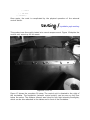
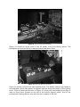
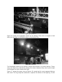
The system was tested in a club-like situation, and was extremely well received.
Even when placed alongside professional lighting equipment, the system was
preferred in many occasions.
introduction /
context and purpose
In club and lounge settings, there is a high demand for the ambience created by
intelligent lighting. This system is geared towards DJs who aspire to further control
of their audience by setting the visual aspect of their shows. It also addresses the
market for consumers building traveling lighting rigs or desiring powerful low-end
lighting solutions.
product overview /
functionality and use
The Pulser system is fully functional, and has been tested for a large variety of
audio inputs. It operates best with music suited for its application – namely, music
that would be found in a club or lounge environment.
// components
The Pulser system is comprised of four discrete components. Its peripherals may be
substituted in order to better suit a particular application.
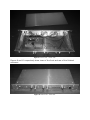
control interface
The control interface is in a standard 19-inch rack-mount package, so that is may
be easily integrated into an existing lighting rig.
Figure 1 shows a depiction of the front side of the unit:
Figure 1. Control interface design – front side.
The controls are placed very intuitively, with screws doubling as a means to divide
the different sections of control. Moving from right to left, the first section consists
of the power switch and an LED that shows when the unit is powered.
The next section consists of a bar graph display of the incoming audio signal, along
with a dial for controlling the gain applied to the signal. Under the desired
operation, the input signal is amplified to span across the entirety of the bar graph
display.
The following two sections correspond to the two output channels. For each section,
the right knob sets the channel’s mode of operation, and the left knob sets the hold
time of each strobe signal. The right-hand channel is called the leader, and the lefthand channel is called the follower. (These are discussed in detail below.) A
feedback LED is provided for each channel so that the user may better see and
control each output.
The last (leftmost) section is for the external control switch. A stereo quarter-inch
jack is provided for plugging the peripheral into the control unit, and an LED is
provided for user feedback of the remote operation.
Figure 2 depicts the rear side of the unit:
Figure 2. Control interface design – rear side.
The inputs and outputs of the unit are placed in accordance with their counterparts
on the front side. Moving again from right to left, the first port is an extra jack for
the external override switch. This jack is provided in addition to the front-side jack
because it may be desired depending on the selected application for the system.
Next are four mono quarter-inch jacks – two for each channel of output.
To the left of these are right- and left-channel RCA inputs for the audio signal.
The last port is for the 5-volt DC power input.
power
The control interface is powered by an AC-DC converter with a 5-volt output. It
draws less than 300 mA of current, and leaves all high power handling to
peripherals.
external control switch
For certain types of operation, the unit relies on the presence of an external control
switch. This is a dual pushbutton device, which can plug into the stereo quarterinch jacks on the control unit.
At present, a dual guitar footswitch is used. This is advantageous for the performing
DJ who whishes to control their lighting – control of the lights leaves their hands
free for playing music.
Note that the external control switch is not needed for the automated operation
mode of the control unit.
breakout boxes
Breakout boxes are used to convert the logic-level signal from the control unit to a
mains-level signal.
The control signal is inputted into a mono quarter-inch jack – the same way that it
comes from the control unit. Each has a parallel quarter-inch output jack, so that
the units may be chained together. Standard instrument cables are suggested for
connecting the units.
The breakout boxes draw their power from a mains-level outlet. They each have
four outlets of output available. They may source a maximum of 10 A, as per the
specifications of the solid-state relays they house.
Note that any number of possible breakout box configurations and applications are
conceivable. The described boxes were fabricated for their versatility.
// modes of operation
The system may operate in any of three modes, as set by the mode knob of the
leader channel on the control unit.
mode one [ automated beat detection ]
In this mode, the control unit derives an automated output based on an analysis of
the input signal. The sensitivity of the output pulses are set by controlling the gain
of the audio. Once set correctly, the gain knob may be left for the duration of
operation.
The user may induce a manual blackout or whiteout by pressing the buttons on the
external controller.
mode two [ user-defined hits ]
In this mode, the output of the device is off by default. The user may induce a
strobe by pressing one of the buttons in the external control unit, or may
enable/disable a whiteout by pressing the other button.
mode three [ programmable strobe pattern ]
In this mode, the user may tap a desired strobe pattern on the peripheral controller
unit. This is extremely useful in situations where the automatic detection algorithm
fails.
The user begins to set a pattern by tapping one of the buttons on the external
controller, and continues to press that button at time intervals corresponding to the
desired strobe pattern. The program is ended when the user presses the other
button. Pressing the termination button also initiates playback of the program.
The program will continue to loop over the time interval between the initial tap and
the termination tap. Repressing the termination tap will re-sync the program at the
instant when it is tapped.
Up to 16 different pulse placements may be programmed for a given lighting
program. A given program is erased when a new program is recorded.
// output channels
The Pulser system drives two output channels, for increased functionality.
channel one [ the leader ]
The leader channel operated precisely as described above. Main venue lighting
should be tied to this channel.
channel two [ the follower ]
The follower channel may be considered an accessory to the first. It has three
modes of operation, as set by its mode knob.
In its first mode, the follower channel simply follows the output of the leader
channel. Both channels produce the same lighting patterns.
In its second mode, the output from the follower channel is turned off.
In its third mode, the follower channel will follow the leader channel only when the
leader is in hit mode.
The follow channel should be tied to lighting reserved for special emphasis.
hardware /
design and implementation
Although it consumed much time, the hardware design and implementation was
relatively straightforward.
// circuit design
The first step in building the system was to design the circuitry for the control unit.
The majority of the circuit consisted of digital components, and thus it was fairly
simple to design.
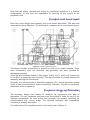
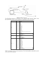
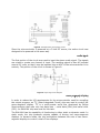
The control unit is based around a PIC 16F877 microcontroller. The microcontroller
comes in a 40-pin DIP package, which simplifies circuit board construction. A pin
diagram for the device is shown below:
Figure 3. PIC16F873/877 pin diagram.
The software for the device was coded using the PIC C IDE, and programmed using
an RJ12 connector. The following diagram shows the basic programming setup for
the microcontroller:
Figure 4. PIC16F873/877 programming circuit.
Since the microcontroller is powered by a 5-volt DC source, the entire circuit was
designed to be powered in the same way.
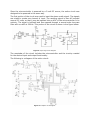
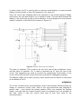
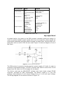
The first portion of the circuit was used to input the stereo audio signal. The signals
are mixed to create one channel of input. The resulting signal is then AC-coupled
around 2.5 volts, so that it may be inputted into an ADC of the microcontroller in its
entirety. The signal is buffered and then passed through a second-order low-pass
filter with a cutoff at 228 Hz. This portion of the circuit is shown in the figure below:
Figure 5. Input stage circuit diagram.
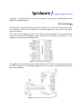
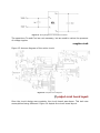
The remainder of the circuit includes the microcontroller and the circuitry needed
for the desired input and output functionality.
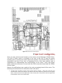
The following is a diagram of the entire circuit:
Figure 6. Complete circuit diagram.
Note that the output channels are driven by operational amplifiers in a follower
configuration, so that they are responsible for sourcing all the current to the
peripheral units.
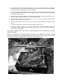
// printed circuit board layout
Once the circuit design was complete, the circuit board was drawn. This task was
accomplished using Ultiboard. The following is a diagram of the circuit board layout:
Figure 7. Printed circuit board layout.
This layout includes connections to ground on each of its output headers. These
were unnecessary since the enclosure was grounded, but were included for
debugging purposes.
There are two mistakes present in this layout. Firstly, the 0- and 5-volt connections
to the RJ12 programmer were reversed. This was corrected by cutting trances and
manually rewiring the connections.
Secondly, the microcontroller’s decoupling capacitor (C1) should have been placed
closer to the microcontroller’s power connections. However, this did not cause any
detectable errors in operation.
// enclosure design and fabrication
The enclosure design was chosen to maximize its ergonomics and ease of
fabrication. The only necessary machining was the drilling of holes for each of the
interface components. An inner mount was necessary for properly attaching the
potentiometers and control knobs. The selected enclosure was purposefully
oversized to simplify fabrication.
An inside view of the completed control unit can be seen in Figure 8.
Figure 8. Control unit – inside view.
Figures 9 and 10 respectively show views of the front and rear of the finished
enclosure.
Figure 9. Control unit – front view.
Figure 10. Control unit – rear view.
No major problems arose while fabricating this piece of hardware. Unfortunately,
the holes were not drilled in a perfect line as desired due to the speed of the unit’s
production.
// breakout box construction
The breakout boxes are used to house the solid-state relays, and package the
mains-level signals in a safe and robust manner. Their wiring was straightforward.
Two holes were drilled in the top face of each for the parallel control line
connections.
Figure 11 shows the completed breakout boxes.
Figure 11. Breakout boxes.
software /
structure and code
The general structure of the code is as follows:
main () {
declare variables
initialize hardware
while (1) {
read audio input
read user-adjusted inputs
update bar graph display
if (mode one is selected) { // automated beat detection
if (whiteout) {
set output
} else if (blackout) {
set output
} else {
process and set automated beat detection output
}
} else if (mode three is selected) { // programmable strobe pattern
if (programming started) {
record program
if (programming terminated) {
begin running program
}
}
if (running program ended) {
start running program from beginning
}
if (programmed beat on current timer count) {
set output
}
} else if (default mode selected) { // user-defined hits
if (whiteout) {
set output
}
if (hit) {
set output
}
}
}
}
The coding was fairly straightforward. The structure and functionality of the
program was limited by the ROM size of the microcontroller. This limit was
exceeded on numerous occasions, and the program was altered to account for this
limitation.
The audio input is digitally amplified by a value taken from the gain potentiometer
and then displayed on the bar graph of LED’s.
The same basic structure was used to produce the lighting pulses in each of the
three modes. A counter variable beat_counter was created to increment by one on
each program cycle. If the value of this variable is under a certain value, the
lighting output is set. The simplest example of this exists in the case of the default
(user-defined hits) state. In this case, the value of beat_counter is reset to zero
whenever the external switch is triggered. If its value is less then a certain
threshold, the lighting output is turned on.
In automated detection mode, the value of beat_counter is set to zero whenever
the audio input is over a certain threshold. This allows the automated detection
algorithm output fixed-length pulses, and gives the lighting display a very clean
feel.
The algorithm for the programmable strobe pattern mode works in a similar
fashion. The array beat_array holds timestamps for each of the beats in a given
program. The first beat always occurs at time zero, as the timing counter is reset at
the start of programming. If the master timing counter is within a certain range of a
programmed beat time, the lights are set on. The length of a recorded program is
recorded in the variable beat_count and the number of beats in a program is stored
in prog_step.
There are independent threshold values for each output channel. These are set by
the user – variables cut1 and cut2 are read from the potentiometer inputs of each
channel and adjusted to extend over a suitable range. These values may be set
differently to account for the differing startup times needed for various types of
lights.
// hardware configuration and initializations
The first portion of the code was used to configure the microprocessor hardware,
and declare and initialize variables. The following code accomplishes this task:
#define SAFE 45
main () {
signed int16 ad_audio_center;
signed int16 ad_audio;
signed int16 ad_gain;
signed int16 ad_cut1;
signed int16 ad_cut2;
float audio;
float gain;
float cut1;
float cut2;
float beat_counter = SAFE; // safe is good enough
float beat_counter_temp;
float beat_count = 0;
signed int beat_state = 0;
signed int prog_enabled = 0;
signed int restart_state = 0;
float beat_array[] = {-1,-1,-1,-1,-1,-1,-1,-1,-1,-1,-1,-1,-1,-1,-1,-1}; // 16
int prog_step = 0;
int i;
int beat_set;
int program_state;
signed int follow;
setup_adc(ADC_CLOCK_INTERNAL);
setup_adc_ports(AN0_AN1_AN2_AN3_AN4);
setup_spi(FALSE);
setup_psp(PSP_DISABLED);
setup_spi(FALSE);
setup_timer_0(RTCC_INTERNAL|RTCC_DIV_1);
setup_timer_1(T1_DISABLED);
portc = 0xFF;
set_adc_channel(0);
delay_ms(500);
ad_audio_center = read_adc();
portc = 0x00;
delay_ms(500);
while (1) {
The value of the audio input is read after the power supply is given time to settle.
This registers the center value for the audio ADC, and ensures that the entire LED
bar graph will be off when there is no audio signal. Therefore, it is assumed that
there is zero audio input until this value has been read.
The program is put in an eternal while loop, so that the remainder of the code will
loop as long as the unit is powered.
// parameter readings
The first part of the continuous program loop is spent reading the parameters from
the microprocessor inputs.
The following code reads the value of the audio from its ADC, half-wave rectifies the
signal, and subtracts the remaining DC offset:
set_adc_channel(0);
delay_us(20);
ad_audio = read_adc();
if (ad_audio > ad_audio_center) {
audio = (float)(ad_audio - ad_audio_center);
} else {
audio = (float)(ad_audio_center - ad_audio);
}
The next portion of the code reads the ADC value of the gain potentiometer. The
audio signal is then amplified by this value.
set_adc_channel(2);
delay_us(20);
ad_gain = read_adc();
gain = (float)(255 - ad_gain) / 10; // amplify up to 27.5x
audio = audio * gain;
Next, the values of cut1 and cut2 are read from their respective ADC’s:
set_adc_channel(4);
delay_us(30);
ad_cut1 = read_adc();
cut1 = (float)(255 - ad_cut1) / 6; // up to 43 loop cycles
set_adc_channel(3);
delay_us(30);
ad_cut2 = read_adc();
cut2 = (float)(255 - ad_cut2) / 6; // up to 43 loop cycles
Finally, the mode of operation for the follower channel is read from its rotary knob:
follow = 0;
if (!input(pin_d4)) {
follow = 1;
} else if (!input(pin_d6)) {
follow = 2;
}
The 20- to 30-ms delays are needed after setting the ADC channels to ensure that
the correct data is read.
// bar graph display
The following code is used to set the bar graph LED display:
if (audio > 120*.03) { // -32 dB
output_high(pin_c0);
} else {
output_low(pin_c0);
}
if (audio > 120*.16) { // -16 dB
output_high(pin_c3);
} else {
output_low(pin_c3);
}
if (audio > 120*.40) { // -8 dB
output_high(pin_c4);
} else {
output_low(pin_c4);
}
if (audio > 120*.63) { // -4 dB
output_high(pin_c5);
} else {
output_low(pin_c5);
}
if (audio > 120*.79) { // -2 dB
output_high(pin_c6);
} else {
output_low(pin_c6);
}
if (audio > 120) { // 0 dB
output_high(pin_c7);
} else {
output_low(pin_c7);
}
The program arbitrarily assumes that an audio value of 120 is an appropriate
threshold, and uses this value for both the LED display and the automated beat
extraction mode.
// state one [ automated beat detection ]
The following code constructs the output signal, if the system is running in
automated beat detection mode:
if (!input(pin_d0)) {
program_state = 0;
if (!input(pin_e0)) { // whiteout, trumps blackout
output_high(pin_c1);
output_high(pin_c2);
output_high(pin_e2);
} else if (!input(pin_e1)) { // blackout
output_low(pin_c1);
output_low(pin_c2);
output_high(pin_e2);
} else { // output
output_low(pin_e2);
beat_counter = beat_counter + 1;
if (audio > 120) {
beat_counter = 0;
}
if (beat_counter < cut1 && follow == 1) {
output_high(pin_c1);
} else {
output_low(pin_c1);
}
if (beat_counter < cut2) {
output_high(pin_c2);
} else {
output_low(pin_c2);
}
}
Although the code algorithm for this mode of operation is straightforward, it
produces the desired results.
// state three [ programmable strobe pattern ]
The following code is used to process the system’s operation if it is running in
programmable strobe pattern mode:
} else if (!input(pin_d2)) {
if (input(pin_e1)) { // if unpressed
if (beat_state == 0) { // if it was previously unpressed
if (program_state != 2) { // if moving from another state
program_state = 2;
beat_counter = 0;
} else {
if (prog_enabled == 0) {
output_high(pin_e2);
prog_enabled = 1;
beat_counter_temp = 0; // start rec
beat_counter = 0; // run new program
prog_step = 0;
beat_count = 0;
for (i = 0; i < 16; i++) {
beat_array[i] = -1;
}
}
beat_state = 1;
beat_array[prog_step] = beat_counter_temp;
prog_step++; // increment num events in program
}
}
} else { // if pressed
if (beat_state == 1) { // if it was previously unpressed
if (program_state != 2) { // if moving from another state
program_state = 2;
beat_counter = 0;
} else {
if (prog_enabled == 0) {
output_high(pin_e2);
prog_enabled = 1;
beat_counter_temp = 0; // start new rec
beat_counter = 0; // run new program
prog_step = 0;
beat_count = 0;
for (i = 0; i < 16; i++) {
beat_array[i] = -1;
}
}
beat_state = 0;
beat_array[prog_step] = beat_counter_temp;
prog_step++; // increment num of events in program
}
}
} // end if
beat_counter_temp = beat_counter_temp + 1;
if (input(pin_e0)) { // if unpressed
if (restart_state == 0) { // if it was previously unpressed
if (prog_enabled == 1) {
output_low(pin_e2); // signal program termination
beat_count = beat_counter_temp; // set prog length
prog_enabled = 0; // allow for reprogramming
}
restart_state = 1;
beat_counter = 0; // restart program
}
} else { // if pressed
if (restart_state == 1) { // if it was previously unpressed
if (prog_enabled == 1) {
output_low(pin_e2); // signal program termination
beat_count = beat_counter_temp; // set prog length
prog_enabled = 0; // allow for reprogramming
}
restart_state = 0;
beat_counter = 0; // restart program
}
} // end if
if (beat_counter >= beat_count &&
beat_count > 1) {
beat_counter = 0;
} else {
beat_counter = beat_counter + 1;
}
if (program_state == 2) {
beat_set = 0;
i = 0;
while (i < 16 && beat_set == 0) {
if ((beat_counter - beat_array[i]) >= 0 && beat_array[i] > -1) {
if ((beat_counter - beat_array[i]) < cut1 && follow == 1) {
output_high(pin_c1);
} else {
output_low(pin_c1);
}
if ((beat_counter - beat_array[i]) < cut2) {
output_high(pin_c2);
} else {
output_low(pin_c2);
}
}
i++;
}
}
This code is dramatically complicated by the fact that the external control switches
are not simply pushbuttons. Rather, they are toggle switches – they change from
an open to a short circuit and back again. This causes a need to run a symmetrical
rising and falling edge detection algorithm.
// state two [ user-defined hits ]
The following code is used to construct the output for the default (user-defined hits)
mode of operation:
} else {
if (program_state != 1) {
program_state = 1;
beat_counter = SAFE;
if (!input(pin_e1)) {
beat_state = 1;
} else {
beat_state = 0;
}
}
if (!input(pin_e1)) { // if pressed
if (beat_state == 0) { // if it was previously unpressed
beat_state = 1;
beat_counter = 0;
output_high(pin_e2);
}
} else { // if unpressed
if (beat_state == 1) { // if it was previously pressed
beat_state = 0;
beat_counter = 0;
}
} // end if
if (beat_counter < SAFE) {
beat_counter = beat_counter + 1;
}
if (input(pin_e0)) { // if no whiteout override
if (input(pin_e1)) {
output_low(pin_e2);
}
if (beat_counter < cut1 && follow > 0) {
output_high(pin_c1);
} else {
output_low(pin_c1);
}
if (beat_counter < cut2) {
output_high(pin_c2);
} else {
output_low(pin_c2);
}
} else { // if whiteout override
output_high(pin_e2);
output_high(pin_c2);
if (follow > 0) {
output_high(pin_c1);
}
}
} // end if
} // end while
} // end main()
Once again, the code is complicated by the physical operation of the external
control switch.
testing /
installation and reactions
This product was thoroughly tested at a recent campus event. Figure 12 depicts the
control unit, as set up for the event.
Figure 12. Control unit.
Figure 13 shows the complete DJ setup. The control unit is situated to the right of
the turntables. The footswitch (external control switch) can be seen on the floor
below the setup. The follower channel was linked to four high-intensity floodlights,
which can be seen attached to the tables and in front of the turntables.
Figure 13. View from behind the DJ booth.
Figure 14 shows an aerial view of the DJ booth, from the balcony above. The
floodlights can be seen facing outwards toward the dance floor.
Figure 14. View from above the DJ booth.
Figure 15 shows a view of the main lighting truss. The leader channel was linked to
six spotlights, which were placed at regular intervals along the length of the lighting
truss. Three of these can be seen in Figure 15, along with the breakout box that is
used to drive them (located to the left of the truss’s support cable). One of the
professional lighting devices may also be seen, slightly to the left.
Figure 15. Lighting truss.
Figure 16 shows the spotlights turned on for testing. They were arranged so that
they each pointed to a different place on the dance floor.
Figure 16. Lighting test.
The floodlights linked to the follower channel were tested in a similar fashion. These
were not used very extensively during the event, because they were quite bright
and flooded the entire venue with light.
Figure 17 shows the same view as Figure 16, except as the room appeared during
the event. The fog helps the audience to capture the effects of the lighting. In this
case, the fog allows the audience to see the path of light beam as it descends from
its respective source.
Figure 17. View from the floor.
Figure 18 shows a view of the lighting from the DJ booth. Once again, the fog helps
the viewer to capture the path of each light.
Figure 18. View from the DJ booth.
The Pulser system was very well received by those attending the event. In many
instances, switching from the professional lighting devices to the lighting provided
by the Pulser system was greeted with much enthusiasm.
From the perspective of the DJ, the Pulser system was an extremely accessible way
of controlling the audience. The footswitch-based overrides and programming
capabilities proved to be convenient, as blackouts and program synchronizations
could be signaled while busy cueing or mixing tracks.
The handiness of the footswitch control also emphasized the difficulty of controlling
the professional lighting devices. They could only be controlled by moving away
from the DJ’s table, and by pushing the buttons found on a master rack-mount
controller unit.
conclusions /
successes and shortcomings
Although this system was relatively simple to imagine, creating each of its
components was fairly time consuming.
The only major setback encountered was the ROM limit of the PIC microcontroller.
This caused the system’s functionality to be more limited than was originally
desired. However, the system still accomplishes its most important task – it is an
automated and intelligent means for controlling lights.
The main improvement to be made is to build a better external controller. If this
device was to house two pushbuttons (rather than toggle switches), the coding
structure could be greatly simplified – possibly allowing for the integration of
increased functionality.
In conclusion, the creation and testing of this system was an extremely enjoyable
and rewarding experience.
credit /
influences and recognitions
The following individuals were essential for the successful creation of the Pulser
system:
Erik Cheever, Professor
Ed Jaoudi, Electronics Specialist
Grant (Smitty) Smith, Machinist
This project was inspired by the author’s experiences as a DJ and desire to explore
the world of lighting aesthetics.
dmxer /
interactive dmx mixer
karl petre / swarthmore college
abstract /
concept and result
The purpose of this project was to build a DMX512 mixer, capable of providing
intelligent lighting output synchronized with an audio signal. The mixer was
intended to become a part of a DJ’s performance setup to allow the performer full
control of venue lighting. The completed system was designed to provide real-time
manipulation of four adjacent DMX channels, which was configured to interface with
the Chauvet Lighting COLORmist system. Hardware from a Behringer DJX400 mixer
was reconfigured to produce the prototype system.
While many components of the system were realized, the selected design did not
prove fully successful in accomplishing its task. The DMX protocol conversion board
did not function as expected, which hindered the completion of the project.
introduction /
purpose and background
In club and lounge settings, there is a high demand for the ambience created by
intelligent lighting. This system is geared towards DJs who aspire to further control
of their audience by fully manipulating the visual aspect of their shows.
// dmx
DMX512 is an RS485-based lighting protocol used for venue lighting systems. It
was developed by the Engineering Commission of USITT.
Devices are linked in a daisy chain configuration, and devices have both input and
output DMX connections. The connectors are five-pin XLR, although only three pins
are always used. The pin connections are as follows:
1.
Data Link Common
2.
Data 1- (Primary Data Link)
3.
Data 1+ (Primary Data Link)
4.
Data 2- (Secondary Data Link)
5.
Data 2+ (Secondary Data Link)
Each DMX data link may control up to 512 addresses, which means that multiple
networks must be used in large applications.
Data is transmitted serially at 250 kilobaud and is grouped into packets. Bytes are
sent with one start bit and two stop bits. The start of a packet is signaled by a
break of at least 88 microseconds. After a mark after break (MAB) signal, up to 512
bytes are sent.
Data is sent starting with the values to be written at address 0. Although the
transmitter must send data for at only 24 channels, all 512 packets of data are sent
in most cases. This corresponds to a minimum refresh rate of 44 Hz. There is no
error detection or correction in DMX.
Many devices used adjacent DMX channels to support complete remote control of
their functionalities.
hardware /
design and implementation
Although it consumed much time, the hardware design and implementation was
relatively straightforward.
// lighting output
The Chauvet COLORmist system was chosen in order to produce a full-spectrum
lighting output. This system consists of three components – the RGB LED lights, a
control interface, and a power converter. The lights are shown in Figure 1.
Figure 1. RGB LED lamps.
Figure 2 shows the control interface. This is used to set the operation mode of the
lights when the system is running without external control. The control unit also
serves as the interface for accepting an incoming DMX signal. The base DMX
address of the system is set on this unit.
Figure 2. COLORmist controller.
Figure 3 shows a diagram of the COLORmist setup, as connected to a controlling
DMX line.
Figure 3. COLORmist connectivity.
The COLORmist system is controlled by four adjacent DMX channels. Table 1 lists
the functionality of each control channel, as specified in the user manual.
DMX Address
Address
Address + 1
Address + 2
Value
000
010
020
030
040
050
060
070
080
090
100
110
120
130
140
150
160
170
180
190
200
210
220
↔
↔
↔
↔
↔
↔
↔
↔
↔
↔
↔
↔
↔
↔
↔
↔
↔
↔
↔
↔
↔
↔
↔
009
019
029
039
049
059
069
079
089
099
109
119
129
139
149
159
169
179
189
199
209
219
255
000 ↔ 255
000 ↔ 002
003 ↔ 249
250 ↔ 255
000 ↔ 255
Address + 3
000
013
026
039
052
065
078
091
104
117
130
143
156
169
182
195
208
221
234
247
↔ 012
↔ 025
↔ 038
↔ 051
↔ 064
↔ 077
↔ 090
↔ 103
↔ 116
↔ 129
↔ 142
↔ 155
↔ 168
↔ 181
↔ 194
↔ 207
↔ 220
↔ 233
↔ 246
↔ 255
000 ↔ 255
Function
Programs
Black
Red
Green
Blue
Yellow
Purple
Light Blue
White
Color Change
Slow Flow 1
Slow Flow 2
Roll Chase 1
Roll Chase 2
Multi Color
Fast Flow 1
Fast Flow 2
Fast Flow 3
Fast Flow 4
2 Color Chase
2 Color Flow
Any Color: Activates Red, Green & Blue Intensity controls
Color Fade
Auto Run
Run Speed
Slow > Fast, (1 step/Minute) > (100 steps/Second)
Any Color (Active)
Red: Intensity: 0% > 100
Flash Speed
Always On
Slow > Fast
Blackout
Any Color (Active)
Green: Intensity: 0% > 100
Color Combinations
Red & Green
Red & Yellow
Red & Blue
Red & Purple
Red & Cyan
Red & White
Green & Yellow
Green & Blue
Green & Purple
Green & Cyan
Green & White
Yellow & Blue
Yellow & Purple
Yellow & Cyan
Yellow & White
Blue & Purple
Blue & Cyan
Blue & White
Purple & Cyan
Purple & White
Any Color (Active)
Blue: Intensity: 0% > 100
Table 1. COLORmist program modes.
Table 2 provides a more concise summary of the functionalities controlled by each
of the unit’s DMX channels.
DMX Address
Function
Address
Program Mode
Address + 1
Red / Run Speed
Address + 2
Green / Flash Speed
Address + 3
Blue / Select Color
Table 2. Summary of COLORmist program modes.
// dmx conversion
Converting the control signals to the DMX512 protocol is accomplished using a
commercial protocol converter.
Figure 4. DMX protocol converter.
The converter accepts two different types of inputs. It can be programmed using an
RS232 connection, which allows the programming of any channel on the DMX
stream. The board also takes 4 analog voltages, and converts these to four
adjacent DMX addresses (as set by DIP switches on the board). The suggested
wiring diagram for the analog inputs is shown in Figure 5.
Figure 5. Analog input wiring diagram.
For this application, the analog inputs are used. The Chauvet system is controlled
by setting the values of four adjacent DMX channels, which coincides with this
functionality of the converter board.
// mixer hardware remapping
The first step in designing the system was to remap the hardware from the
Behringer mixer. Figure 1 shows the mixer, as viewed from above.
Figure 6. Top view of the mixer.
The majority of the mixer’s functionality was stripped. The only parts that remained
as originally intended were the CH-1 (channel 1), the channel 1 Beat Assist, the
Master Level, and MIC (microphone) sections.
The reason for choosing this particular mixer was for its automatic BPM estimation
functionality. Under normal operating conditions, the mixer would estimate the
tempo of each incoming channel to facilitate easy mixing by an inexperienced DJ.
The estimated tempos are displayed by seven-segment numeric LED displays. The
critical part of this functionality is that an LED on the mixer blinks on the mixer’s
estimation of the beat. The blinks of this LED are used to synchronize the intelligent
lighting output.
The following mapping was selected for the remainder of the mixer:
1.
The monitor section functions as the overrides. The CH-1 switch selects a blackout, the CH-2
switch selects a whiteout, and the MASTER switch selects a beat-synchronized strobe. The
gain knob selects the strobe rate to be used when in the strobe override mode. The user may
select from a range of strobe rates – from once per measure up to four times per beat.
2.
The TEMPO DIFFERENCE and TIME OFFSET LED’s are used to display the current phrase
position of the audio track. There are 16 possible positions, which correspond to 4 measures of
4 beats each. The CH-2 tempo assist button may be pressed to reset the phrase position. The
CH-2 tempo assist LED flashes when the music is at the top of a phrase.
3.
The crossfader is used to navigate between lighting output modes, just as it was originally
intended to switch from one track to the next. This gives the DJ the ability to “mix” between
modes of lighting output.
4.
The CF CURVE button is used to set the output in an automatic progression mode. When this
switch is set, the lighting output will change at the top of every phrase.
5.
The channel 2 PHONO/CD selector is used to toggle between program-set and user-set output
modes.
6.
The channel 2 gain (slide) potentiometer is used to set the lighting output program. In manual
(user-set) mode, the selected program will be immediately displayed on the lighting output. In
program-set mode, this will be the next program set when the user slides the crossfader.
7.
The channel 2 trim knob sets the overall brightness of the lighting output.
8.
The channel 2 HIGH, MID, and LOW trim potentiometers are used to set the values of the red,
green, and blue outputs when the mixer is in manual mode. Alternatively, they may be used
to set their designated control parameters for another user-selected operation mode.
This mixer was also selected because of the prototyping space available in its
interior.
// circuit design
The first step in building the system was to design the circuitry for the control unit.
The majority of the circuit consisted of digital components, and thus it was fairly
simple to design.
microcontroller
The control unit is based around a PIC 16F877 microcontroller. The microcontroller
comes in a 40-pin DIP package, which simplifies circuit board construction. A pin
diagram for the device is shown in Figure 7.
Figure 7. PIC16F873/877 pin diagram.
The software for the device was coded using the PIC C IDE, and programmed using
an RJ12 connector. Figure 8 shows the basic programming setup for the
microcontroller.
Figure 8. PIC16F873/877 programming circuit.
Since the microcontroller is powered by a 5-volt DC source, the entire circuit was
designed to be powered in the same way.
audio input
The first portion of the circuit was used to input the stereo audio signal. The signals
are mixed to create one channel of input. The resulting signal is then AC-coupled
around 2.5 volts, so that it may be inputted into an ADC of the microcontroller in its
entirety. This portion of the circuit is shown in Figure 9.
Figure 9. Input stage circuit diagram.
seven-segment display
In order to reduce the I/O requirements for the microcontroller used for compiling
the output program, an I2C (Inter-Integrated Circuit) chip was used to control the
seven-segment display. I2C is a multi-master serial bus developed by Philips
Semiconductor that uses only two data lines – serial data (SDA) and serial clock
(SCL). An SAA1064 chip was used for this task.
The SAA1064 has the capability of functioning in either static or dynamic mode. In
static mode, the chip produces outputs capable of driving two seven-segment
displays. In dynamic mode, the chip multiplexes between two sets of two sevensegment displays to control a total of four displays.
In either mode, the IC is used to drive a common anode display. A common anode
display ties the anodes of each LED segment to the same pin.
Since the circuit was designed before the operation of the seven-segment display
was known, the chip was wired to run in dynamic mode. This was done because the
display to be driven had a total of three displays. A wiring diagram for the dynamic
mode of operation of the SAA1064 is shown in Figure 10.
Figure 10. Dynamic mode wiring of the SAA1064.
The value of capacitor C10 is used to set the clock rate of the multiplexer circuit,
and the value of capacitor C11 is used to decouple the IC from the rest of the
circuit. The transistors are used to provide the multiplexing functionality of the
circuit. Extra VDD and VSS connections were provided for debugging purposes.
The address (ADR) line is tied to ground, which means that the device is referenced
at an address of 0x70.
architecture
The circuit includes three microcontrollers, which communicate asynchronously by
means of numerous control lines. Each of the microcontrollers was assigned a
specific task – one controls the phrase position LEDs, one compiles the lighting
output, and one tells the output compiler when to progress from one program to
the next. Table 3 lists the control lines sent to and from each of the
microcontrollers.
Microcontroller
Inputs
Outputs
Phrase Position
Beat
Phrase Position Reset
Phrase Position LEDs (16)
Phrase Start LED
Phrase Start
Event Detector
Output Compiler
Beat
Phrase Start
Audio
Program Auto Step
Program Lock
Program Search
Crossfader
Strobe Rate
Program Step
Beat
Blackout
Input Selector
Manual Blackout
Manual Whiteout
Manual Strobe
Program Step
Blackout
Beat
7-Segment Display (2)
Blackout LED
Whiteout LED
Strobe LED
Red
Green
Blue
Table 3. Microcontroller I/O.
dmx control board
As stated earlier, the inputs to the DMX protocol converter board are analog. In
order to produce suitable output signals from the microcontroller, these signals are
pulse-width modulated and then passed through low-pass filters. Second-order lowpass filters with a cutoff of 200 Hz were used. Figure 11 shows a diagram of one of
the filters.
Figure 11. Second-order low-pass filter.
The DMX protocol conversion board requires a power supply of 9 volts. In order to
produce an appropriate supply, a DC/DC converter was used to convert the 15-volt
supply from the mixer to a 9-volt supply for the board.
The device used was an NDL1209SC isolated wide input single output DC/DC
converter, provided by C&D Technologies. The device comes in a 7-pin SIP
package, and produces a 9-volt output voltage from a 9- to 18-volt input voltage.
The wiring diagram for the device is shown in Figure 12.
Figure 12. Wiring diagram for the DC/DC conversion.
The capacitors Cin and Cout are not necessary, but are used to reduce the presence
of voltage ripples.
complete circuit
Figure 13 shows a diagram of the entire circuit.
Figure 13. Complete circuit diagram.
// printed circuit board layout
Once the circuit design was complete, the circuit board was drawn. This task was
accomplished using Ultiboard. Figure 14 depicts the circuit board layout.
Figure 14. Printed circuit board layout.
// mixer board reconfiguration
There are two printed circuit boards on the interior of the Behringer DJX400 Mixer.
The first of these, which is mounted to the rear of the unit, is used for power
handling and to process the audio inputs and outputs. The second board, which is
mounted to the top of the unit, is connected to all of the user controls, and is
responsible for implementing the functionalities of the mixer. There was ample
space inside the enclosure to mount both the DMX conversion board and the DMXer
control board.
Almost all modifications were made to the main processing board of the mixer. The
following list summarizes the alterations that took place:
1.
All LED’s were originally set flush to the control panel by spacers. These were removed, and
mounted flush to the circuit board. The spacers were then shortened, placed over the original
LED’s, and used to hold new LED’s flush to the control panel. This process left the original LED
functionalities of the mixer board intact.
2.
The traces leading to each of the pushbuttons were cut. Wires were soldered to the exposed
pins of the buttons on the bottom side of the board. This meant that the buttons would appear
to the main mixer board as if they were never pressed.
3.
The seven-segment LED display was cut from the board, and remounted so that its pins were
no longer connected to the original circuitry. Rather, the pins were connected to wires leading
to the DMXer control board.
4.
The leads from the potentiometers were cut to disconnect them from the original board. Wires
were then soldered to the remainder of the potentiometer legs.
5.
The main board is powered by sources of +5, +15, and -15 volts. Connections were made to
the pins for the ground, +5, and +15 lines.
6.
The bar graph display of the mixer was rewired so that it always displays the master output
levels.
7.
A three-pin female XLR connector was mounted to the rear of the unit.
8.
In order to match the gain of the mixer’s phono input, the beat feedback signal was
transferred through a potentiometer mounted to the phono inputs. The left and right phono
channels were tied together.
The reverse engineering of the mixer was quite laborious, but nonetheless produced
desirable results.
Figures 15 through 20 illustrate various aspects of the fabrication process. Figure
15 shows a view of the completed interior of the mixer. The mixer’s main circuit
board may be seen attached to the underside of the top panel.
Figure 15. Fabrication – complete view.
Figure 16 shows an alternate view of the completed mixer interior. The wired
connections to the underside of the mixer’s main board may be seen.
Figure 16. Fabrication – view of the main mixer board.
Figure 17 shows a view of the DMXer board (left) and the DMX protocol conversion
board (right).
Figure 17. Fabrication – view of the DMXer board (left) and the DMX conversion board (right).
Figure 18 shows a view of the DMX output port. Note that a 3-pin XLR connection
was used, in conflict with the protocol standard. This was used to interface with the
3-pin XLR connection of the COLORmist system.
Figure 18. Fabrication – view of the DMX output.
Figure 18 shows a closer view of the DMX protocol conversion board. The board’s
analog inputs may be seen to the back right of the board.
Figure 19. Fabrication – view of the DMX converter board.
Figure 20 shows the connections made to the mixer’s audio inputs. Both the DMXer
audio input connections (right) and the feedback loop connections (left) may be
seen.
Figure 20. Fabrication – view of the audio inputs, phono feedback, and DMX output.
software /
structure and code
The general structure of the code is as follows:
// microcontroller one [ phrase position ]
The first microcontroller is dedicated for tracking the phrase position of the
incoming audio signal. There are two inputs to the microcontroller, which include a
signal taken from the beat synchronization LED and a switch for allowing the user
to rest the phrase position.
The first portion of the code is used to establish and initialize variables:
main() {
float ad_beat;
float ad_beat_p;
int8 beat = 0;
int8 safe = 500; // at least 84 to cover the duration of the multiplexed pulse
int8 ad_t_min = 100;
int8 ad_t_max = 112;
int8 phrase_state = 1;
...
The software keeps track of the current phrase position, and uses phrase_state to
store this value. This is initialize to 1, which corresponds to the first beat of the
phrase.
Some difficulty was encountered with the handling of the signal from the mixer’s
beat synchronization LED. It was found that the LED’s on the mixer board were all
multiplexed. Although they appeared to be either continuously on or continuously
off, the LEDs were in fact flickering between states at a rate faster than perceivable
by the human eye. Each pulse of the beat synchronization LED in fact consists of
about a dozen pulses.
In order for the phrase position state machine to function as desired, it would have
to change states at the onset of a train of pulses, rather than at the onset of each
pulse. This was done using a debouncing counter, which assumes that the pulses
last for a certain duration, and that each beat of the music occurs after a certain
period of time. The value of safe stores the length of each debouncing period. When
the first pulse of the LED is detected, the value of beat is initialized to this value,
and must count all the way to zero before another beat may be detected.
In order to correctly detect each multiplexed pulse, the signal from the LED is taken
into an 8-bit ADC of the microcontroller. Using an oscilloscope, it was determined
that each pulse corresponds to an ADC input voltage of about 2 volts. The software
looks for inputs between ad_t_min and ad_t_max to find these pulses.
Each individual pulse detection is also debounced, to account for the fact that
input signal to the ADC often switches from 0 to 5 volts. This is done so that
algorithm will not detect instantaneous crossings through the input range as
onset of an LED pulse. This debouncing is accomplished simply by searching
values within the specified window over two adjacent code execution cycles.
the
the
the
for
The next segment of the code initializes each of the phrase position LEDs to a low
(off) state.
output_low(pin_c0);
output_low(pin_c1);
output_low(pin_c2);
output_low(pin_c3);
output_low(pin_c4);
output_low(pin_c5);
output_low(pin_c6);
output_low(pin_c7);
output_low(pin_d0);
output_low(pin_d1);
output_low(pin_d2);
output_low(pin_d3);
output_low(pin_d4);
output_low(pin_d5);
output_low(pin_d6);
output_low(pin_d7);
The program is then sent into its execution loop, which executes as long as the
microcontroller is powered.
while (1) {
A delay is used to slow the clock rate of each execution cycle. A delay of 400
microseconds was chosen so that the ADC input would be sampled at least twice
over the time that each multiplexed LED pulse is within the specified input range.
delay_us(400);
The ADC data is then collected. The value of beat is reset to its debounced safe
value if both the current and previous ADC inputs are within the specified range.
set_adc_channel(0);
delay_us(20);
ad_beat = read_adc();
if (beat == 0 && ad_beat > ad_t_min && ad_beat < ad_t_max && ad_beat_p > ad_t_min
&& ad_beat_p < ad_t_max) {
beat = safe;
}
If the value of beat is safe, then the state machine should switch states.
The output pin e1 is set to quickly pulse on each beat. (It pulses for one execution
cycle, or approximately 400 microseconds.) This is the signal that is then sent to
the mixer’s channel 1 phono input to create a feedback loop. If the mixer’s input is
set to this phono signal, then the current tempo will perpetuate itself until it is
changed by the user. This occurs because the mixer assumes that the tempo will
not change until it registers a change from its audio signal.
This feedback override functionality is extremely useful in situations where the
mixer’s tempo detection functionality fails. The override gives the user the ability to
correctly define the tempo and phrase position of the music.
if (beat == safe) {
phrase_state = phrase_state + 1;
output_high(pin_e1);
if (phrase_state > 16) {
phrase_state = 1;
}
} else {
output_low(pin_e1);
}
If the phrase reset button is pressed by the user, the phrase position state machine
is reset.
if (!input(pin_a1)) {
phrase_state = 1;
output_low(pin_c0);
output_low(pin_c1);
output_low(pin_c2);
output_low(pin_c3);
output_low(pin_c4);
output_low(pin_c5);
output_low(pin_c6);
output_low(pin_c7);
output_low(pin_d0);
output_low(pin_d1);
output_low(pin_d2);
output_low(pin_d3);
output_low(pin_d4);
output_low(pin_d5);
output_low(pin_d6);
output_low(pin_d7);
}
The value of beat decrements by 1 each execution cycle. A beat may only be
detected when the value of beat is 0.
if (beat > 0) {
beat = beat - 1;
}
The remainder of the code executes the state machine. The machine assumes that
the phrase position LED from the previous state is the only LED to be reset to low
(off).
if (phrase_state == 1) {
output_high(pin_e0);
} else {
output_low(pin_e0);
}
if (phrase_state == 1) {
output_low(pin_c7);
output_high(pin_d0);
}
if (phrase_state == 2) {
output_low(pin_d0);
output_high(pin_d1);
}
if (phrase_state == 3) {
output_low(pin_d1);
output_high(pin_d2);
}
...
if (phrase_state == 15) {
output_low(pin_c5);
output_high(pin_c6);
}
if (phrase_state == 16) {
output_low(pin_c6);
output_high(pin_c7);
}
ad_beat_p = ad_beat;
} // end while
} // end main
The software algorithm utilized by this microcontroller worked as designed, and
produced the desired functionality for its portion of the user interface.
// microcontroller two [ event processor ]
This microprocessor is used to determine when the output compiling microprocessor
should change the program being displayed.
The final functionality of the second microprocessor was more limited than initially
designed. This occurred because the microprocessor was damaged before the full
software implementation could be completed.
As with the phrase position microcontroller, the signal from the mixer’s beat
synchronization LED was inputted through one of the microcontroller’s ADC ports.
The same algorithm is used to track the phrase position of the audio signal. The
signal from the phrase start LED of the phrase position microcontroller was also
input into this microcontroller, so that the algorithm could appropriately respond to
user-defined phrase position resets.
The following code executes functionalities associated with all user interface
handling:
main() {
float ad_beat;
float ad_beat_p;
float ad_phrase;
int8 beat = 0;
int8 safe = 500; // at least 84 to cover
int8 ad_t_min = 100;
int8 ad_t_max = 112;
int8 phrase_state = 1;
setup_adc(ADC_CLOCK_INTERNAL);
setup_adc_ports(AN0_AN1_AN2_AN3_AN4);
setup_spi(FALSE);
setup_psp(PSP_DISABLED);
setup_spi(FALSE);
setup_timer_0(RTCC_INTERNAL|RTCC_DIV_1);
setup_timer_1(T1_DISABLED);
while (1) {
delay_us(400);
set_adc_channel(2);
delay_us(20);
ad_beat = read_adc();
if (beat == 0 && ad_beat > ad_t_min && ad_beat < ad_t_max && ad_beat_p > ad_t_min
&& ad_beat_p < ad_t_max) {
beat = safe;
}
if (phrase_state == 1 && !input(pin_a4)) { // if auto step on phrase
output_high(pin_e0);
}
if (beat == safe) {
phrase_state = phrase_state + 1;
output_high(pin_d0); // clean beat for U8
if (phrase_state > 16) {
phrase_state = 1;
}
} else { // automatically assume
output_low(pin_d0);
output_low(pin_e0);
}
set_adc_channel(3);
delay_us(20);
ad_phrase = read_adc();
if (ad_phrase > 100) {
phrase_state = 1;
}
if (beat > 0) {
beat = beat - 1;
}
if (!input(pin_c0)) { // pass through
output_high(pin_e1);
} else {
output_low(pin_e1);
}
ad_beat_p = ad_beat;
} // end while
} // end main
This code also passes a cleaned beat synchronization signal to the output compiler
(pin d0).
// microcontroller three [ output compiler ]
The final microcontroller is used to compile the output for controlling the lighting
system.
Work on the software for this microcontroller was also terminated prematurely due
to damage incurred to the microcontroller, and due the improper functioning of the
DMX protocol converter. However, several portions of the microcontroller’s
functionality were coded.
override management
During runtime, the user has the ability to override the normal operation of the
system to produce a whiteout, a blackout, or a strobe pattern. The following code
manages these three override states of the lighting output:
main() {
float ad_gain;
float ad_crossfade;
float ad_strobe;
int1 blackout_state = 0;
int1 strobe_state = 0;
int1 whiteout_state = 0;
...
while (1) {
if (!input(pin_d6)) { // strobe
output_high(pin_d1);
while(!input(pin_d6)) {
}
strobe_state++;
}
if (strobe_state) {
output_high(pin_d1);
} else {
output_low(pin_d1);
}
if (!input(pin_d5)) { // whiteout
output_high(pin_d2);
while(!input(pin_d5)) {
}
whiteout_state++;
}
if (whiteout_state) {
output_high(pin_d2);
output_high(pin_e0);
output_high(pin_e1);
output_high(pin_e2);
} else {
output_low(pin_d2);
}
if (!input(pin_d4)) { // blackout
output_high(pin_d3);
while(!input(pin_d4)) {
}
blackout_state++;
}
if (blackout_state) {
output_high(pin_d3);
output_low(pin_e0);
output_low(pin_e1);
output_low(pin_e2);
} else {
output_low(pin_d3);
}
delay_ms(20);
} // end while
} // end main
seven-segment display
Code was also implemented for driving the seven-segment display by means of the
I2C chip.
Figure 21 depicts the serial data format for writing to the IC.
Figure 21. SAA1064 data writing format.
Table 4 shows the meanings of the subaddressing values that can be set in the
instruction byte.
SC
0
0
0
0
1
1
1
1
SB
0
0
1
1
0
0
1
1
SA
0
0
0
1
0
1
0
1
Subaddress
00
01
02
03
04
05
06
07
Function
Control Register
Digit 1
Digit 2
Digit 3
Digit 4
Reserved
Reserved
Reserved
Table 4. SAA1064 subaddressing.
Table 5 shows the various settings available for the control byte.
Bit Setting
C0 = 0
C0 = 1
C1 = 0/1
C2 = 0/1
C3 = 1
C4 = 1
C5 = 1
C6 = 1
Meaning
Static mode.
Dynamic mode.
Digits 1 and 3 are blanked / not blanked.
Digits 2 and 4 are blanked / not blanked.
All segments on for segment test.
Adds 3 mA to segment output current.
Adds 6 mA to segment output current.
Adds 12 mA to segment output current.
Table 5. SAA1064 control bits.
The C compiler used to program the microcontrollers comes with built-in I2C
functionality. This is initialized using the following preprocessor command:
#use I2C(master, sda=PIN_C4, scl=PIN_C3)
The following code initializes variables and the processor hardware settings.
main() {
float ad_gain;
int gain;
...
delay_ms(10);
The SAA1064 chip must then be initialized. The following commands are aimed at
completing the initialization. All segments are briefly turned on, and then turned off
again.
i2c_start();
i2c_write(0x70);
i2c_write(0x00);
i2c_write(0b00011110);
i2c_stop();
delay_ms(10);
i2c_start();
i2c_write(0x70);
i2c_write(0x00);
i2c_write(0b00000110);
i2c_write(0x00);
i2c_write(0x00);
i2c_stop();
The following execution loop reads the input from the mixer’s channel 2 volume
potentiometer, and displays a corresponding numeric value (from 0 to 9) on the
seven-segment display.
while (1) {
set_adc_channel(0);
delay_us(20);
ad_gain = read_adc();
ad_gain = (ad_gain / 255 * 10) - 0.5;
gain = (int)ad_gain;
i2c_start();
i2c_write(0x70);
i2c_write(0x01);
if (gain == 9) {
i2c_write(0b00111111);
}
if (gain == 8) {
i2c_write(0b00000011);
}
if (gain == 7) {
i2c_write(0b01101101);
}
if (gain == 6) {
i2c_write(0b01100111);
}
if (gain == 5) {
i2c_write(0b01010011);
}
if (gain == 4) {
i2c_write(0b01110110);
}
if (gain == 3) {
i2c_write(0b01111110);
}
if (gain == 2) {
i2c_write(0b00100011);
}
if (gain == 1) {
i2c_write(0b01111111);
}
if (gain == 0) {
i2c_write(0b01110111);
}
i2c_stop();
} // end while
} // end main
Difficulty was encountered while programming the microcontroller to utilize the
seven-segment display control chip. It would work on occasion, after attempting
numerous initialization bit streams. However, no fixed method of initialization could
be established. Assuming the IC can be correctly initialized, the above program loop
will work as designed.
conclusions /
successes and shortcomings
Although this system was relatively simple to imagine, creating each of its
components was fairly time consuming.
The main setback encountered was the improper functioning of the DMX protocol
conversion board. The board was chosen in part due to cost considerations; future
revisions to the design should incorporate a protocol converter of a higher quality.
The main improvement to be made is changing the method used to communicate
with the protocol converter. This design relied on the creation of analog signals,
which proved difficult to produce. Using a serial data communication scheme (such
as an RS232 link) would be much easier to incorporate. Moreover, this would allow
for a more configurable product that could control a variety of DMX compliant
lighting systems.
In conclusion, the creation of this system was an extremely educational and
rewarding experience.
credit /
influences and recognitions
The following individuals were essential for the work completed on the DMXer
system:
Bruce Maxwell, Professor
Erik Cheever, Professor
Ed Jaoudi, Electronics Specialist
Grant (Smitty) Smith, Machinist
Alex Benn, Classmate
This project was inspired by the author’s experiences as a DJ and desire to explore
the world of lighting aesthetics.