1
Mazda6
Training
Manual
FOREWORD
This manual explains each component or
system operation and function for
the Mazda6.
For proper repair and maintenance,
a thorough familiarization with this manual
is important, and it should always be kept
in a handy place for quick and easy
reference.
All the contents of this manual, including
drawings and specifications, are the latest
available at the time of printing.
As modifications affecting repair or
maintenance occur, relevant information
supplementary to this volume will be made
available at Mazda dealers. This manual
should be kept up-to-date.
Mazda Motor Corporation reserves
the right to alter the specifications and
contents of this manual without obligation
or advance notice.
All rights reserved. No part of this book
may be reproduced or used in any form or
by any means, electronic or
mechanicalincluding photocopying and
recording and the use of any kind of
information storage and retrieval
systemwithout permission in writing.
Mazda Motor Corporation
HIROSHIMA, JAPAN
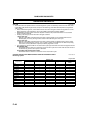
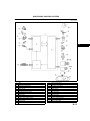
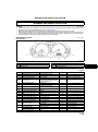
APPLICATION:
This manual is applicable to vehicles
beginning with the Vehicle Identification
Numbers (VIN) shown on the following
page.
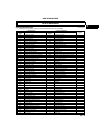
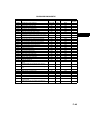
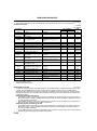
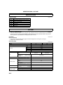
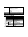
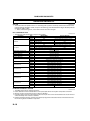
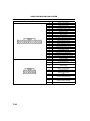
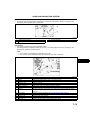
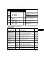
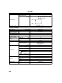
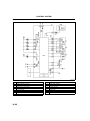
CONTENTS
Title
Section
General Information
GI
Engine
B
Lubrication System
D
Cooling System
E
Fuel and Emission Control Systems
F
Engine Electrical System
G
Clutch
H
Manual Transaxle
J
Automatic Transaxle
K
Front and Rear Axles
M
Steering System
N
Braking System
P
Suspension
R
Body
S
Body Electrical System
T
Heater and Air Conditioner Systems
U
© 2002 Mazda Motor Corporation
PRINTED IN The Netherlands, MARCH 2002
33591E02C
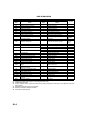
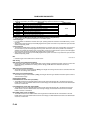
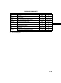
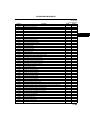
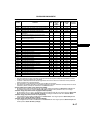
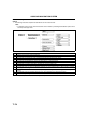
VEHICLE IDENTIFICATION NUMBERS (VIN)
U.K. specs.
JMZ GG12820#
JMZ GG14320#
JMZ GG14820#
JMZ GG12F20#
JMZ GG12F50#
JMZ GG14F20#
JMZ GG14F50#
100001
100001
100001
100001
100001
100001
100001
European (L.H.D.) specs.
JMZ GG1232✻# 100001
JMZ GG1282✻# 100001
JMZ GG1432✻# 100001
JMZ GG1482✻# 100001
JMZ GG12F2✻# 100001
JMZ GG12F5✻# 100001
JMZ GG14F2✻# 100001
JMZ GG14F5✻# 100001
GCC specs.
JM7 GG32F✻✻#
JM7 GG34F✻✻#
JM7 GG42F✻✻#
JM7 GG44F✻✻#
100001
100001
100001
100001
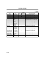
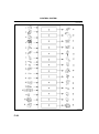
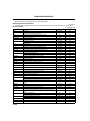
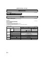
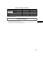
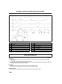
RELATED MATERIALS
Engine Workshop Manual L8, LF, L3 . . . . . . . . . . . . . .
Manual Transaxle Workshop Manual
G35MR . . . . . . . . . . . . . . . . . . . . . . . . . . . . . . . . . . . .
Automatic Transaxle Workshop Manual
FN4AEL . . . . . . . . . . . . . . . . . . . . . . . . . . . . . . . . . . . .
Automatic Transaxle Workshop Manual
Supplement FN4AEL . . . . . . . . . . . . . . . . . . . . . . . . .
Mazda6 Wiring Diagram
(European (L.H.D.), GCC specs.) . . . . . . . . . . . . . . . .
Mazda6 Wirinig Diagram
(U.K. specs.) . . . . . . . . . . . . . . . . . . . . . . . . . . . . . . . . .
Mazda6 Bodyshop Manual
(European (L.H.D. U.K.), GCC specs.) . . . . . . . . . . . .
* : Indicates the printing location
E: Europe
0: Japan
17311*02C
17321*02C
16231098E
17461*02C
55391*02C
55401*02C
33601*02C
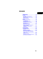
GENERAL INFORMATION
GI
G
I
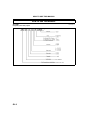
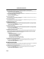
HOW TO USE THIS MANUAL ............................. GI-2
VIN CODE.......................................................... GI-2
UNITS ................................................................... GI-4
UNITS TABLE .................................................... GI-4
NEW STANDARDS .............................................. GI-5
NEW STANDARDS TABLE ............................... GI-5
GI1
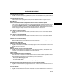
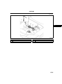
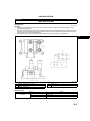
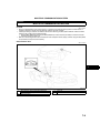
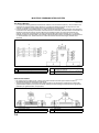
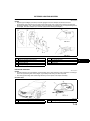
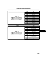
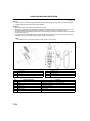
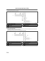
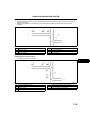
HOW TO USE THIS MANUAL
HOW TO USE THIS MANUAL
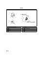
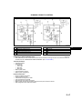
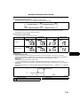
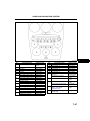
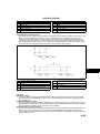
VIN CODE
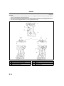
European (L.H.D. U.K.) specs.
A6E201000001T01
A6E2021T001
GI2
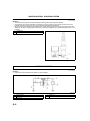
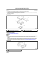
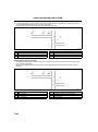
HOW TO USE THIS MANUAL
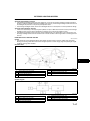
GCC specs.
GI
A6E2021T002
End Of Sie
GI3
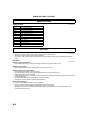
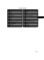
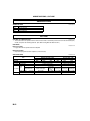
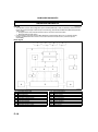
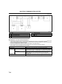
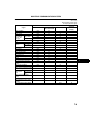
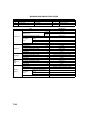
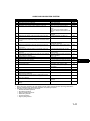
UNITS
UNITS
UNITS TABLE
Electrical current
Electric power
Electric resistance
Electric voltage
Length
Negative pressure
Positive pressure
Torque
Volume
Weight
A6E201200002T01
A (ampere)
W (watt)
ohm
V (volt)
mm (millimeter)
in (inch)
kPa (kilo pascal)
mmHg (millimeters of mercury)
inHg (inches of mercury)
kPa (kilo pascal)
kgf/cm2 (kilogram force per square
centimeter)
psi (pounds per square inch)
N·m (Newton meter)
kgf·m (kilogram force meter)
kgf·cm (kilogram force centimeter)
ft·lbf (foot pound force)
in·lbf (inch pound force)
L (liter)
US qt (U.S. quart)
Imp qt (Imperial quart)
ml (milliliter)
cc (cubic centimeter)
cu in (cubic inch)
fl oz (fluid ounce)
g (gram)
oz (ounce)
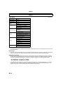
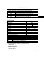
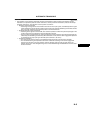
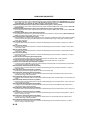
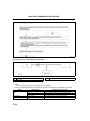
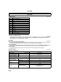
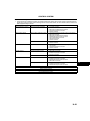
Conversion to SI Units (Système International d'Unités)
• All numerical values in this manual are based on SI units. Numbers shown in conventional units are converted
from these values.
Rounding Off
• Converted values are rounded off to the same number of places as the SI unit value. For example, if the SI unit
value is 17.2 and the value after conversion is 37.84, the converted value will be rounded off to 37.8.
Upper and Lower Limits
• When the data indicates upper and lower limits, the converted values are rounded down if the SI unit value is
an upper limit and rounded up if the SI unit value is a lower limit. Therefore, converted values for the same SI
unit value may differ after conversion. For example, consider 2.7 kgf/cm2 in the following specifications:
210260 kPa {2.12.7 kgf/cm2, 3038 psi}
270310 kPa {2.73.2 kgf/cm2, 3945 psi}
• The actual converted values for 2.7 kgf/cm2 are 265 kPa and 38.4 psi. In the first specification, 2.7 is used as
an upper limit, so the converted values are rounded down to 260 and 38. In the second specification, 2.7 is
used as a lower limit, so the converted values are rounded up to 270 and 39.
End Of Sie
GI4
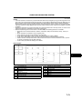
NEW STANDARDS
NEW STANDARDS
GI
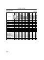
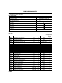
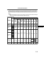
NEW STANDARDS TABLE
A6E202800020T01
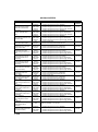
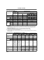
• Following is a comparison of the previous standard and the new standard.
New Standard
Abbreviation
AP
ACL
A/C
BARO
B+
CMP sensor
CAC
CLS
CTP
CPP
CIS
CS sensor
CKP sensor
DLC
DTM
DTC
DI
DLI
EI
ECT
EM
EVAP
EGR
FC
FF
4GR
FSO
solenoid
GEN
GND
HO2S
IAC
IAT
KS
MIL
MAP
MAF sensor
MFL
OBD
OL
Name
Accelerator Pedal
Air Cleaner
Air Conditioning
Barometric Pressure
Battery Positive Voltage
Brake Switch
Calibration Resistor
Camshaft Position Sensor
Charge Air Cooler
Closed Loop System
Closed Throttle Position
Clutch Pedal Position
Continuous Fuel Injection System
Control Sleeve Sensor
Crankshaft Position Sensor
Data Link Connector
Diagnostic Test Mode
Diagnostic Trouble Code(s)
Distributor Ignition
Distributorless Ignition
Electronic Ignition
Engine Coolant Temperature
Engine Modification
Engine Speed Input Signal
Evaporative Emission
Exhaust Gas Recirculation
Fan Control
Flexible Fuel
Fourth Gear
Fuel Pump Relay
Previous Standard
Abbreviation
Vb
EGI
CSP sensor
Name
Accelerator Pedal
Air Cleaner
Air Conditioning
Atmospheric Pressure
Battery Voltage
Stoplight Switch
Corrected Resistance
Crank Angle Sensor
Intercooler
Feedback System
Fully Closed
Clutch Position
Electronic Gasoline Injection System
Control Sleeve Position Sensor
Crank Angle Sensor 2
Diagnosis Connector
Test Mode
Service Code(s)
Spark Ignition
Direct Ignition
Electronic Spark Ignition
Water Thermo
Engine Modification
Engine RPM Signal
Evaporative Emission
Exhaust Gas Recirculation
Fan Control
Flexible Fuel
Overdrive
Circuit Opening Relay
Remark
#6
#6
#1
#2
#3
Fuel Shut Off Solenoid
FCV
Fuel Cut Valve
#6
Generator
Ground
Heated Oxygen Sensor
Idle Air Control
IDM Relay
Incorrect Gear Ratio
Injection Pump
Input/Turbine Speed Sensor
Intake Air Temperature
Knock Sensor
Malfunction Indicator Lamp
Manifold Absolute Pressure
Mass Air Flow Sensor
Multiport Fuel Injection
On-Board Diagnostic
Open Loop
FIP
Alternator
Ground/Earth
Oxygen Sensor
Idle Speed Control
Spill Valve Relay
With heater
Fuel Injection Pump
Pulse Generator
Intake Air Thermo
Knock Sensor
Malfunction Indicator Light
Intake Air Pressure
Airflow Sensor
Multiport Fuel Injection
Diagnosis/SelfDiagnosis
Open Loop
#6
#6
GI5
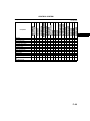
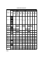
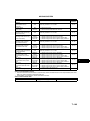
NEW STANDARDS
New Standard
Abbreviation
OC
O2S
PNP
PSP
PCM
PAIR
AIR
SAPV
SFI
Name
Output Speed Sensor
Oxidation Catalytic Converter
Oxygen Sensor
Park/Neutral Position
PCM Control Relay
Power Steering Pressure
Powertrain Control Module
Pressure Control Solenoid
Name
Vehicle Speed Sensor 1
Catalytic Converter
Oxygen Sensor
Park/Neutral Range
Main Relay
Power Steering Pressure
Engine Control Unit
Line Pressure Solenoid Valve
Pulsed Secondary Air Injection
Secondary Air Injection System
Pump Speed Sensor
NE Sensor
Secondary Air Injection
Secondary Air Injection System
Secondary Air Pulse Valve
Sequential Multipoint Fuel Injection
Shift Solenoid A
Shift Solenoid B
3GR
TWC
TB
TP sensor
TCV
TCC
Previous Standard
Abbreviation
ECU
Shift Solenoid C
Third Gear
Three Way Catalytic Converter
Throttle Body
Throttle Position Sensor
Timer Control Valve
Torque Converter Clutch
Transmission (Transaxle) Control
TCM
Module
Transmission (Transaxle) Fluid
Temperature Sensor
TR
Transmission (Transaxle) Range
TC
Turbocharger
VSS
Vehicle Speed Sensor
VR
Voltage Regulator
VAF sensor Volume Air Flow Sensor
Warm Up Three Way Catalytic
WUTWC
Converter
WOT
Wide Open Throttle
TCV
Reed Valve
Sequential Fuel Injection
1-2 Shift Solenoid Valve
Shift A Solenoid Valve
2-3 Shift Solenoid Valve
Shift B Solenoid Valve
3-4 Shift Solenoid Valve
3rd Gear
Catalytic Converter
Throttle Body
Throttle Sensor
Timing Control Valve
Lockup Position
ECAT Control Unit
ATF Thermosensor
Inhibitor Position
Turbocharger
Vehicle Speed Sensor
IC Regulator
Air flow Sensor
Catalytic Converter
Fully Open
Remark
#6
#4
Pulsed
injection
#6
Injection
with air
pump
#6
#5
#1 : Diagnostic trouble codes depend on the diagnostic test mode
#2 : Controlled by the PCM
#3 : In some models, there is a fuel pump relay that controls pump speed. That relay is now called the fuel pump
relay (speed).
#4 : Device that controls engine and powertrain
#5 : Directly connected to exhaust manifold
#6 : Part name of diesel engine
End Of Sie
GI6
ENGINE
B
B
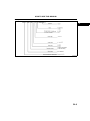
ABBREVIATIONS ..................................................B-2
ABBREVIATIONS ................................................ B-2
OUTLINE ................................................................ B-2
OUTLINE OF CONSTRUCTION.......................... B-2
FEATURES .......................................................... B-2
ENGINE PERFORMANCE CURVE..................... B-3
SPECIFICATIONS ............................................... B-4
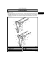
STRUCTURAL VIEW...........................................B-4
ENGINE .................................................................. B-5
CYLINDER HEAD COVER .................................. B-5
CYLINDER HEAD ............................................... B-5
CYLINDER HEAD GASKET ................................ B-6
CYLINDER BLOCK ............................................. B-6
CRANKSHAFT, MAIN BEARING......................... B-8
BALANCER UNIT ................................................ B-9
CRANKSHAFT PULLEY .................................... B-11
ENGINE FRONT COVER .................................. B-12
PISTON, PISTON RING, PISTON PIN .............. B-13
CONNECTING ROD,
CONNECTING ROD BEARING...................... B-14
DRIVE BELT ...................................................... B-15
ENGINE MOUNT ............................................... B-16
VALVE MECHANISM ........................................... B-19
VALVE MECHANISM......................................... B-19
CAMSHAFT ....................................................... B-20
CAMSHAFT SPROCKET................................... B-22
CRANKSHAFT SPROCKET .............................. B-23
TIMING CHAIN, CHAIN TENSIONER ............... B-24
VALVE, VALVE SPRING, VALVE SEAL,
VALVE GUIDE ................................................ B-25
TAPPET ............................................................. B-26
VALVE MECHANISM......................................... B-27
VARIABLE VALVE TIMING ACTUATOR........... B-33
OIL CONTROL VALVE (OCV) ........................... B-33
B1
ABBREVIATIONS , OUTLINE
ABBREVIATIONS
ABBREVIATIONS
A/C
ABDC
ATDC
BBDC
BTDC
DOHC
EX
IN
OCV
P/S
PCV
SST
TDC
A6E220102000T01
Air conditioner
After bottom dead center
After top dead center
Before bottom dead center
Before bottom dead center
Double overhead camshaft
Exhaust
Intake
Oil control valve
Power steering
Positive crankcase ventilation
Special service tool
Top dead center
End Of Sie
OUTLINE
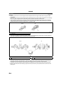
OUTLINE OF CONSTRUCTION
A6E220202000T01
• The new L8 engine models (1.8L) has been adopted for European specs.
• The new LF engine models (2.0L) has been adopted.
• The new L3 (with variable valve timing mechanism) engine models (2.3L) has been adopted for European
specs.
End Of Sie
FEATURES
Improved engine performance
• The variable valve timing mechanism has been adopted for L3 engine models (2.3L).
A6E220202000T02
Reduced engine weight
• Main parts (cylinder head and cylinder block) made of aluminum alloy.
Reduced engine noise and vibration
• The cylinder head is made of aluminum alloy.
• The cassette type balancer unit has been adopted for the L3 engine models (2.3L).
• Silent timing chain has been adopted.
• A deep skirt type and forms the ladder frame structure with the integrated main bearing cap has been adopted
for the cylinder block.
• The crankshaft pulley with torsional damper has been adopted.
• The engine mount of pendulum type has been adopted.
Improved serviceability
• The drive belt of serpentine type has been adopted.
• Tension of the drive belt is adjusted automatically with an auto-tensioner.
• Timing chains have been adopted to eliminate the need for replacement.
• The engine front cover with service hole has been adopted. (for unlocking the chain adjust ratchet, and
securing the tensioner arm).
End Of Sie
B2
OUTLINE
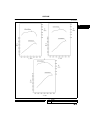
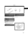
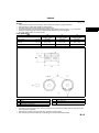
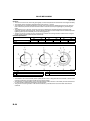
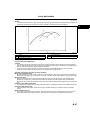
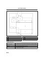
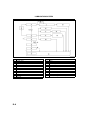
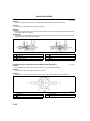
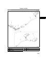
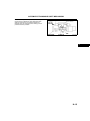
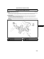
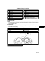
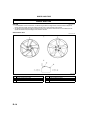
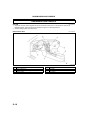
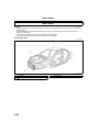
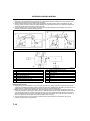
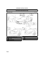
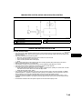
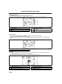
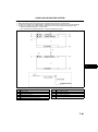
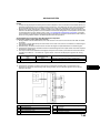
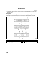
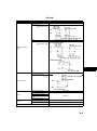
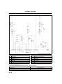
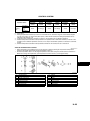
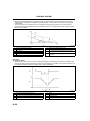
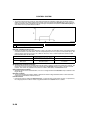
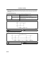
ENGINE PERFORMANCE CURVE
A6E220202000T04
B
AME2202N001
1
Engine speed
2
3
Output
Torque
B3
OUTLINE
End Of Sie
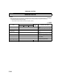
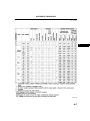
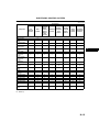
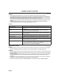
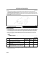
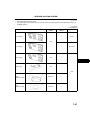
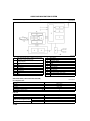
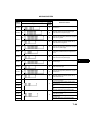
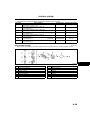
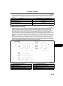
SPECIFICATIONS
A6E220202000T03
Item
Type
Cylinder arrangement and number
Combustion chamber
Valve system
Displacement
(ml {cc, cu in})
Bore × stroke
(mm {in})
Compression ratio
Compression pressure
(kPa {kgf/cm2, psi} [rpm])
Open
Close
Valve timing
Open
EX
Close
IN
Valve
(mm {in})
clearance
EX
IN
Specification
LF
L3
Gasoline, 4-cycle
In-line, 4-cylinder
Pentroof
DOHC, timing chain driven, 16 valves
1,999
2,261
1,798
{1,798, 109.7}
{1,999, 121.9}
{2,261, 137.9}
83.0 × 83.1
87.5 × 83.1
87.5 × 94.0
{3.27 ×3.27}
{3.44 ×3.27}
{3.44 × 3.70}
10.8:1
10.8:1
10.6:1
1,750 {17.85, 253.8}
1,720 {17.54,
1,430 {14.58, 207.4}
[300]
249.5} [300]
[290]
4
4
025
33
52
037
37
37
42
4
4
5
0.22 {0.0087} 0.28 {0.011} [Engine cold]
0.27 {0.011} 0.33 {0.012} [Engine cold]
L8
BTDC (°)
ABDC (°)
BBDC (°)
ATDC (°)
End Of Sie
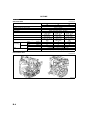
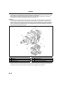
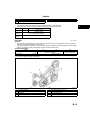
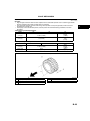
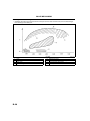
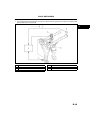
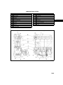
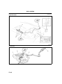
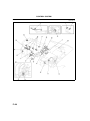
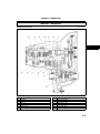
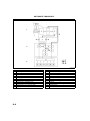
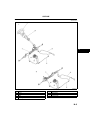
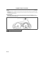
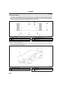
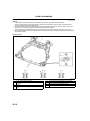
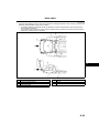
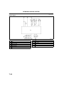
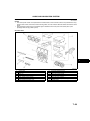
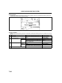
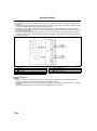
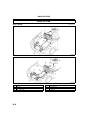
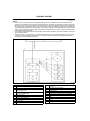
STRUCTURAL VIEW
A6E220202000T05
AME2202N002
End Of Sie
B4
ENGINE
ENGINE
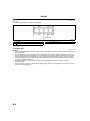
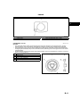
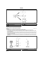
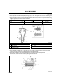
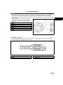
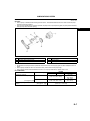
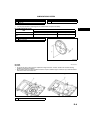
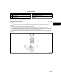
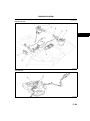
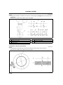
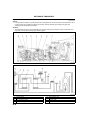
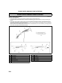
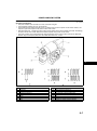
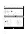
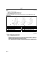
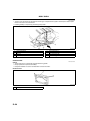
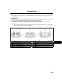
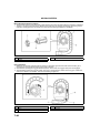
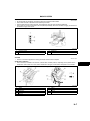
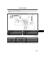
CYLINDER HEAD COVER
A6E222410100T01
Structure
• The cylinder head cover is made of integrated aluminum alloy, which is lightweight and sound absorbent.
• The oil filler cap is a screw-in type. The boss for installing the camshaft position (CMP) sensor is provided at
the rear of the cylinder head cover.
• L3 engine models has a hole for installing the oil control (OCV) valve.
.
AME2224N001
1
2
Camshaft position (CMP) sensor
Oil control (OCV) valve attachment hole (L3)
3
Oil filler cap
End Of Sie
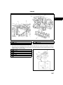
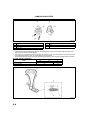
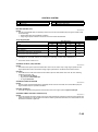
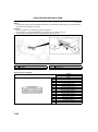
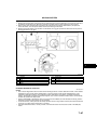
CYLINDER HEAD
A6E222410100T02
Structure
• The cylinder head is made of a high heat conductive, lightweight aluminum alloy, which has been quenched.
• Compact, pentroof-type combustion chambers have been adopted. The spark plugs are mounted at the top of
the combustion chambers to improve combustion efficiency.
• The intake/exhaust port layout is a cross flow type, (the angle between two valves is 39°, the two intake valves
and the two exhaust valves per cylinder) which improves air intake/exhaust efficiency.
• The cylinder head bolt is a plastic region tightening bolt, which is tightened in five motions. It insures a stable
axis during tightening.
AME2224N002
.
1
2
3
4
Cylinder head bolt
Exhaust side
Intake side
Engine front side
5
6
7
The angle between two valves
Intake port
Exhaust port
B5
B
ENGINE
End
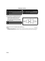
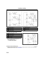
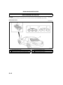
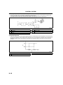
Of Sie HEAD GASKET
CYLINDER
A6E222410271T01
Structure
• Cylinder head gaskets are 2 layer-metal gaskets.
AME2224N400
.
1
2
Beat plate
Shim
3
A-A sectional view
End Of Sie
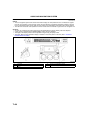
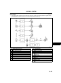
CYLINDER BLOCK
A6E222410300T01
Structure
• The cylinder block is made of aluminum alloy, which is cast with the cast iron liner, improving heat radiation and
decreasing weight.
• The cylinder block is a deep skirt type and forms the ladder frame structure with the integrated main bearing
cap. The water jacket of the cylinder block is a closed deck type. Its higher rigidity reduces vibration and noise.
• The cylinder block has the oil separator cover on the opposite side of the fresh air intake, the PCV (positive
crankcase ventilation) valve and the oil separator function with an part for installing the PCV valve, to improve
blow-by gas ventilation efficiency.
• The tab for alignment, used to install the upper main journal and the lower main bearing, has been
decommissioned.
• The main bearing cap bolt is a plastic region tightening bolt, which is to be tightened in two motions. It insures
a stable axis during tightening.
B6
ENGINE
B
AME2224N003
.
1
2
3
Oil separator cover
PCV valve
Main bearing cap
4
5
Oil separator cover attachment part
Cylinder block
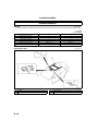
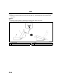
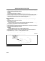
• The service hole for installing the SST, which is used for detect the No.1 cylinder's TDC position, is located at
the right side of the cylinder block. The TDC position can be detected when the SST edge touches the cutting
surface of the No.1 counter weight.
.
1
2
3
4
5
6
7
Cylinder block
No.1 cylinder
Service hole
SST
No.1 cylinder TDC position
No.1 piston
Crankshaft counter
AME2224N004
B7
ENGINE
End
Of Sie
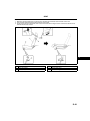
CRANKSHAFT,
MAIN BEARING
A6E222411301T01
Structure
• Cast iron 5 axle-hole 4 counter weight has been adopted for the L8 engine models and LF engine models
crankshafts.
• Cast iron 5 axle-hole 8 counter weight has been adopted for the L3 engine models crankshaft. The shrinkage
fitted drive gear is attached to the crankshaft and the crankshaft drives the balance shaft.
• The conventional positioning key has been decommissioned and the tightening pressure of the crankshaft
pulley tightening bolt secures the installation part of the crankshaft sprocket. When installing the crankshaft
sprocket, always use the SST and align the No.1 cylinder to TDC.
AME2224N005
.
1
Drive gear
• The oil line for supplying oil to each journal is provided in the crankshaft. And the crank pin and the fillets on
both sides of journal are rolled so that they bear the heavy loads.
AME2224N006
.
1
Oil passage
2
Fillet roll area
• The upper and lower main bearings are made of aluminum alloy and the upper side No.3 journal bearing is
integrated with the thrust bearing. The upper main bearing has the oil grooves and the oil holes.
• The upper and lower bearings' positioning tabs for installing the main journal have been decommissioned.
• Measure and attach the main bearings (upper and lower) so that they are positioned at the center the main
bearing cap.
B8
ENGINE
B
AME2224N007
.
1
2
3
4
Upper main bearing
Lower main bearing
Thrust bearing
Supplying engine oil
5
6
7
2 holes Supplying engine oil
Main bearing cap
Main bearing
• Three kinds of main bearings are available depending on the oil clearance.
(mm {in})
Bearing
Color
size
Standard Green
0.25 {0.01}
Oversize
0.50 {0.02}
Oversize
Bearing thickness
2.5062.509 {0.09870.0988}
2.6282.634 {0.10350.1037}
2.7532.759 {0.10840.1086}
End Of Sie
BALANCER UNIT
Outline
• The cassette type balancer, which is separated
from the engine, has been adopted for the L3
engine models to reduce vibration from the
engine.
A6E222411301T02
.
1
2
Cassette type balancer unit
balance shaft
AME2224N401
B9
ENGINE
Structure
• The balancer unit is configured with two balancer shafts (No.1 and No.2) with weights, the balancer unit case
and the adjust shim which adjusts the amount of backlash in the crankshaft.
• The two balancer shafts (No.1 and No.2) are driven by the drive gear which is attached to the crankshaft.
• The balancer unit cannot be disassembled because it is a precision unit.
Operation
• The rotary motion is transmitted from the drive gear, which is between the back of the No.3 cylinder and the
No.4 main journal, directly to the No.1 balance shaft with driven gear. Then the balance unit transmits the
rotation motion to the No.2 balance shaft. The ratio of gears, which are attached to No.1 and No. 2 balancer
shafts, has been set so that the gear rotates at twice the velocity of the crankshaft. The balancer shaft's rotation
velocity counterbalances (generate the force in the opposite direction) the rotation inertial force (secondary
inertial rotation force) from the crankshaft.
AME2224N402
.
1
2
3
4
Adjust shim
Crankshaft
Engine front
Balancer unit case
5
6
7
8
Weights
No.2 balance shaft
Drive gear
No.1 balance shaft with driven gear
• Replace the adjust shim to adjust backlash. There are 40 kinds of adjuster shim depending on the thickness.
To determine the kind, check the engraved identification mark (2 digits) on the adjust shim.
B10
ENGINE
B
AME2224N403
.
1
Cylinder block
2
Engraved identification mark (2 digits)
End Of Sie
CRANKSHAFT PULLEY
A6E222411371T01
Structure
• The crankshaft position (CKP) signal detecting blade has been adopted for the crankshaft pulley. And the
torsional damper, which prevents the crankshaft from wobbling, has also been adopted for the crankshaft.
• The positioning key slot, which is used for attaching the pulley to the crankshaft, has been decommissioned.
For aligning the crankshaft pulley to the crankshaft, use the positioning hole on the engine front cover and the
crankshaft pulley.
• Crankshaft pulley rock bolt is the plastic region tightening bolt, which can be tightened in 2 motions. It insures a
stable axis during tightening.
.
1
2
3
4
5
Elevation view
Sectional view
Braid for CKP sensor signal detection
Hole for pulley positioning
Torsional damper
AME2224N012
End Of Sie
B11
ENGINE
ENGINE FRONT COVER
A6E222401001T01
Structure
• The engine front cover is made of aluminum alloy, and is integrated with the No.3 engine-mounting bracket, to
improve noise absorption and decrease weight.
• The hole for crankshaft pulley positioning bolt, the service hole for unlocking the chain adjuster ratchet, and the
service hole for securing the tensioner arm when loosening the timing chain, are on the engine front cover.
• The oil line and the integrated oil filter are on the L3 engine front cover.
AME2224N011
.
1
2
3
4
Elevational view
Service hole for tensioner arm fixation
Service hole for chain tensioner lock release
No.3 engine mount bracket
End Of Sie
B12
5
6
7
8
Bolt hole crankshaft pulley positioning
Back view
Oil filter
Oil passage to OCV
ENGINE
PISTON, PISTON RING, PISTON PIN
A6E222411010T01
Structure
• The pistons are made of aluminium alloy, which withstands heat and is highly conductive.
• The piston skirt is coated with graphite to reduce friction.
• The offset pistons are used to reduce piston-slapping noise.
• To prevent the piston from being reassembled in the wrong direction, the front mark (←) is on the piston.
• Pistons and connecting rods cannot be disassembled because they are shrinkage fit.
• L3 engine models piston has a valve recess.
Piston Specification.
ITEM
Outer diameter
mm {in}
Offset quantity
Compression
height:HC
Piston height: HD
mm {in}
L8
82.96582.995
{3.26643.2675}
0.8 {0.04}
LF
87.46587.495
{3.44353.4435}
0.8 {0.04}
L3
87.46587.495
{3.44353.4435}
0.8 {0.04}
mm {in}
28.5 {1.122}
28.5 {1.122}
28.5 {1.122}
mm {in}
51.0 {2.0078}
51.0 {2.0078}
51.0 {2.0078}
AME2224N008
.
1
2
3
4
Piston side view
Offset
Outer diameter
Piston upper surface view
5
6
7
Install arrow facing engine front
Engine front side
Valve rises
• The following piston rings are used. Top ring: barrel face ring, Second ring: taper under cut ring, Oil ring: two
scuff rings and an expander.
• The piston pin is made of chrome steel alloy, which has superior rigidity.
• The connecting rod and the piston pin are shrinkage fit, and cannot be disassembled.
B13
B
ENGINE
AME2224N009
.
1
2
3
Top ring sectional view
Second ring sectional view
Oil ring sectional view
4
5
Side rail
Expander
End Of Sie
CONNECTING ROD, CONNECTING ROD BEARING
A6E222411211T01
Structure
• Connecting rod is made of structural sintered alloy to improve rigidity.
• The connecting rod, the piston, and the piston pin are shrinkage fit, and cannot be disassembled.
• The connecting rod bolt is the plastic region tightening bolt, which is tightened in two steps to insure a stable
axis during tightening.
• The conventional positioning tab has been decommissioned for the connecting rod bearing. When installing the
bearing, measure the position of the bearing so that the position gets to the center of the connecting rod and
the bearing cap, and install it.
• The big end of the connecting rod and the connecting rod cap were originally formed as a single unit and then
it was cut into the connecting rod and the cap. Using the form of the cutting surface, align the connecting rod
and the cap.
AME2224N010
.
1
Enlargement
B14
2
Connecting rod
ENGINE
3
4
Fracture side
Connecting rod bearing cap
5
Connecting rod bearing
• The upper lower bearing of the connecting rod bearing is made of aluminum alloy.
• There are three kinds of connecting rod bearings depending on the oil clearance.
Bearing size
Color
Standard
Green
0.50 {0.02}
Oversize
0.25 {0.01}
Oversize
B
Bearing thickness (mm {in})
1.4961.502
{0.05890.0591}
1.7481.754 {0.06880.0690}
1.6231.629 {0.06390.0641}
End Of Sie
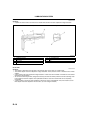
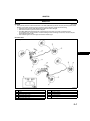
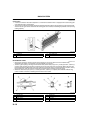
DRIVE BELT
A6E222415800T01
Structure
• The drive belt is a serpentine type, which uses a V-ribbed belt to drive the supplemental units. This shortens
the length of engine and makes it easier to service.
• The front drive belt's auto tensioner, in which the coil spring is embedded, has been adopted for the drive belt's
tension. The tensioner pulley automatically maintains the drive belt's tension.
Drive Belt Specification.
ITEM
L8
Belt length size
mm {in}
Belt width size
mm {in}
( ) is A/C non-equipping vehicle specification.
LF
About 2,255 {88.78}
(About 2,160 {85.04})
About 20.5 {0.81}
L3
About 2,305 {90.75}
(About 2,210 {87.01})
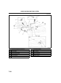
.
AME2224N013
1
2
3
4
P/S oil pump pulley
Drive belt
Idler pulley
Generator pulley
5
6
7
8
Front drive belt auto tensioner
Crankshaft pulley
A/C compressor pulley
Water pump pulley
End Of Sie
B15
ENGINE
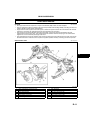
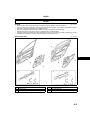
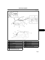
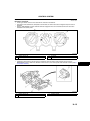
ENGINE MOUNT
A6E222439000T03
Outline
• The layout of the engine mounting is pendulum type, which reduces the noise in the cabin.
• The engine supported at three points, and simplification of engine mount composition parts is attained.
• The No.3 engine mounting rubber, which is an oil-filled type, has been adopted to reduce the noise in the
cabin.
• The surface of No.3 engine joint bracket and the No.1 engine-mounting rubber is made of aluminum alloy to
decrease weight.
AME2224N014
.
1
2
3
No.3 engine joint bracket
No.3 engine mount rubber
No.1 engine mount rubber
B16
4
5
6
No.1 engine mount bracket
No.4 engine mount bracket
No.4 engine mount rubber
ENGINE
Structure
• The surface of No.1 engine mounting rubber is made of aluminum alloy. The form is torque rod structure, which
regulates the conventional rubber function and the rotation from the power train, and it has a vibration isolator.
• The No.3 engine mounting rubber is oil-filled for noise reduction and vibration isolation.
• The No.3 engine-mounting bracket is integrated with the aluminum alloy engine front cover.
AME2224N015
.
1
2
3
No.3 engine joint bracket
No.1 engine mount rubber
Rubber part
4
5
No.3 engine mount rubber sectional view
Oil
• The engine is supported at the following three points: front part of the engine (No.3 engine mounting), one side
of the transaxle (No.1 engine mounting), and rear upper part of the transaxle (No.4 engine mounting). The
supporting point at the side of the tranaxle (No.1 engine mounting) has been set at the transaxle's lowest edge.
With this layout, the No.1 engine mounting absorbs the rotation force, generated under the engine torque's
fluctuation and transmitted to the power train, and distributes the rotation force to the front and rear part of the
engine (pendulum).
B17
B
ENGINE
AME2224N016
.
1
2
3
4
5
6
Power train system upper surface
No.3 engine mount
Engine
Vehicle front
Vehicle rear
No.1 engine mount
End Of Sie
B18
7
8
9
10
11
12
Transaxle
No.4 engine mount
Power train system back
Engine front
Torque
Engine back
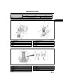
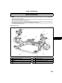
VALVE MECHANISM
VALVE MECHANISM
VALVE MECHANISM
A6E221112111T08
Outline
• There are two intake ports and two exhaust ports per No. 1 cylinder. Totally 16 valves are directly driven by two
camshafts.
• The variable valve timing mechanism, which insures the best valve timing depending on the drive condition by
constantly changing the phase of the intake port side camshaft, has been adopted for the L3 engine models.
Structural view
AME2211N001
.
1
2
3
4
5
6
Camshaft
Timing chain
Camshaft sprocket
Tensioner arm
Chain tensioner
Crankshaft sprocket
7
8
9
10
11
Chain guide
Valve assembly
Tappet
Oil control valve (OCV)
Variable valve timing actuator
B19
B
VALVE MECHANISM
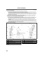
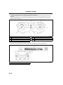
CAMSHAFT
End Of Sie
A6E221112420T01
Structure
• The cast iron 5 axis-hole, which has great rigidity, has been adopted for the camshaft to insure higher reliability.
• The endplay of the camshaft is regulated at the rear of the No. 1 journal.
• The lubricating oil is supplied through the oil supply hole at each journal. Additionally the cam nose part has
been chilled to improve the abrasion resistance and to make the cam hill part lightweight by shortening the
width.
• The positioning pin or key slot, which was used when installing the camshaft sprocket to the edge of the
camshaft, has been decommissioned. And the lubrication process has been adopted for the camshaft sprocket
tightening bolt to prevent instability in the axis during tightening.
• There is an oil line, by which the oil is supplied to the variable valve timing actuator, located at the L3 engine
models intake port side camshaft (front of camshaft).
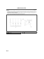
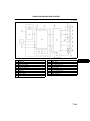
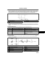
Camshaft Specification.
L8
ITEM
LIFT
Overlap
(mm{in})
(°)
IN
7.5 {0.29}
LF
EX
7.7 {0.30}
IN
8.8 {0.34}
8
L3
EX
7.7 {0.30}
8
IN
9.1 {0.35}
EX
7.8 {0.31}
30
AME2211N004
.
1
2
3
TDC
Variable domain
EX
4
5
IN
BDC
• The detection unit or the camshaft position (CMP) sensor, which is integrated with the camshaft, is at the intake
port side camshaft for L8 engine models and LF engine models.
• The detection unit (trigger plate) for the camshaft position (CMP) sensor is at the intake port side camshaft for
L3 (with variable valve timing mechanism) engine models.
• The groove for securing the No.1 TDC for the camshaft, is provided at the rear of the intake and exhaust
camshaft.
B20
VALVE MECHANISM
B
AME2211N005
AME2211N006
.
1
2
3
4
Intake camshaft
Exhaust camshaft
Thrust
Cam nose
5
6
7
8
Cam journal
Cam heel
Detection part for CKP sensors
SST
End Of Sie
B21
VALVE MECHANISM
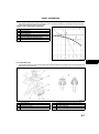
CAMSHAFT SPROCKET
A6E221112420T02
Structure
• The sintered alloy, which has high rigidity, has been adopted for the camshaft sprocket and has been
quenched to improve the abrasion resistance at the contact point with the timing chain.
• L3 engine models intake port side camshaft sprocket is integrated (cannot be disassembled) with the variable
valve timing actuator.
AME2211N009
.
1
2
Camshaft sprocket
Variable valve timing actuator
End Of Sie
B22
VALVE MECHANISM
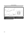
CRANKSHAFT SPROCKET
A6E221112420T03
Structure
• High-strength chromium steel has been adopted for the crankshaft sprocket. Due to carburizing protection,
abrasion resistance at all chain contact points is increased.
• The crankshaft sprocket consists of the timing chain sprocket and oil pump sprocket, which have been
integrated into a single unit.
• The keyway on the crankshaft sprocket, used to position the crankshaft during installation, has been
eliminated.
Timing Drive Sprocket Specification.
ITEM
L8
Outer diameter
(mm {in})
About
47.955 {1.8880}
Tooth width
(mm {in})
About
7.35 {0.289}
LF
L3
About
48.495
{1.9093}
About
8.03
{0.316}
LF
L3
About
48.495
{1.9093}
About
5.93 {0.242}
Oil Pump Drive Sprocket Specification.
ITEM
L8
Outer diameter
(mm {in})
About
47.955 {1.8880}
Tooth width
(mm {in})
About
6.15 {0.242}
AME2211N010
.
1
2
3
Oil pump drive sprocket
Timing chain drive sprocket
Engine front
4
5
Outer diameter
Tooth width
End Of Sie
B23
B
VALVE MECHANISM
TIMING CHAIN, CHAIN TENSIONER
A6E221112040T01
Structure
• The timing chain is the silent chain (link grounding type), by which the tapping noise caused by matching each
sprocket is reduced.
• Engine oil inside the engine front cover lubricates the timing chain and each sprocket. The pin part of the timing
chain is nitrite-treated to improve abrasion resistance.
Timing Chain Specification.
ITEM
Pitch size
Pitch number
L8
(mm {in})
LF
8 {0.32}
134
L3
6.35 {0.25}
174
AME2211N002
.
1
2
3
4
5
Camshaft sprocket
Tensioner arm
Chain tensioner
Chain guide
Crankshaft sprocket
6
7
8
9
Timing chain
Pitch size
Pitch
Link
• The timing chain tensioner is the oil pressure type chain tensioner. The tension of the timing chain is kept
constant, using the oil pressure and the spring force in the chain tensioner.
• The tension of the timing chain is kept constant by the oil pressure and the piston spring force.
• The oil pressure type chain tensioner is configured with the following parts: Piston spring, which depresses the
tensioner arm, Check ball which maintains pressing in the tensioner arm.
B24
AME2211N003
VALVE MECHANISM
.
1
2
3
4
5
6
7
8
9
Hole for a rachet lock
Oil supply hole
Check ball
Piston spring
Piston
Rack
Ratchet
Ratchet spring
Cross-section
B
End
Of Sie
VALVE,
VALVE SPRING, VALVE SEAL, VALVE GUIDE
A6E221112111T02
Structure
• The valves are heat-resistant steel. There are two intake valves, two exhaust valves per No.1 cylinder.
VALVE SPEC.
ITEM
L8
Valve full length
(mm {in})
Intake valve umbrella diameter
(mm {in})
Exhaust valve umbrella diameter
(mm {in})
Stem diameter
(mm {in})
LF
Intake valve: About 101.6 {4.000}
Exhaust valve: About102.6 {4.039}
About 32.5 {1.28}
About 35 {1.38}
About 28
About 30 {1.18}
{1.10}
Intake valve: About 5.5 {0.22}
Exhaust valve: About 5.5 {0.22}
L3
• The intake valve and the exhaust valve are treated with the tufftride process to improve abrasion resistance.
• The valve spring is an uneven outer dimension type. It has been improved by reducing the size of the upper
seat.
• The valve guide is made of the sintered alloy to improve abrasion resistance.
• The valve seat is integrated with the lower valve spring seat to simplify the unit and improve its serviceability.
.
1
2
3
4
5
6
Valve keeper
Upper valve spring seat
Valve spring
Valve seal
Valve guide
Valve
AME2211N008
End Of Sie
B25
VALVE MECHANISM
TAPPET
A6E221112111T03
Structure
• The tappet is a shimless tappet which is integrated with the shim.
• Besides the tappet, the grounding surface of the cam is phosphate-coated to smooth the surface and improve
abrasion resistance.
• To adjust the valve clearance, replace the tappet. There are 35 kinds of tappets depending on the thickness.
To distinguish the difference, check the engraved identification mark (3 digits).
Tappet Specification.
Discernment mark
725625
602122
100000
Tappet thickness (mm {in})
3.7253.625 {0.14670.1427}
3.6023.122 {0.14180.1229}
3.1003.000 {0.12200.1181}
The number of jumps (mm {in})
0.025 {0.00098}
0.02 {0.00078}
0.025 {0.00098}
AME2211N007
.
1
2
3
Tappet
Camshaft
Tappet sectional view
End Of Sie
B26
4
5
6
Cam lob contact surface
Valve stem contact surface
Identification mark position
VALVE MECHANISM
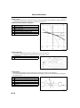
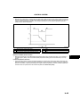
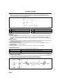
VALVE MECHANISM
A6E221112111T07
Outline
• A variable timing mechanism, which realizes optimum valve timing according to engine operation conditions by
continuously modifying the phases of the intake camshaft and crankshaft, has been adopted.
B
AME2211N013
.
1
2
3
Torque
Engine speed
Low-middle speed engine
4
5
High speed engine
Engine with variable valve timing mechanism
Variable Valve Timing Mechanism
Function
• The variable valve timing mechanism continuously modifies the phases of the variable valve timing actuator
and the intake camshaft using hydraulic pressure controlled by the oil control valve (OCV) so that optimal valve
timing is obtained according to engine operation conditions.
• The oil control valve (OCV) operation is based on signals from the PCM according to engine operation
conditions and it controls hydraulic pressure to the variable valve timing actuator.
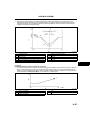
Operation and purpose according to driving condition
Idling range, light load range
• Due to a reduction in the amount of overlap, less combusted gas is returned to the intake port. This stabilizes
idle speed in the idling range, improving fuel economy, and also ensures engine stability in the light load range.
Medium load range
• Overlap amount has been increased and the EGR ratio inside the cylinder is higher. This reduces engine
friction loss (pumping loss), lowering the combustion temperature and reducing the amount of NOx the in
exhaust gas. The amount of hydrocarbon emission has also been reduced through reignition of non-combusted
gas.
Heavy load, low-middle speed range
• The intake valve is closed early, and high volumetric efficiency is obtained to improve low-middle speed torque.
Heavy load, high speed range
• Timing for intake valve closure is delayed and high volumetric efficiency is obtained to improve maximum
output.
When temperature is low
• The overlap amount has been minimized to prevent combusted gas from returning to the intake port and to
reduce the additional fuel injection amount. This improves fuel economy and stabilizes fast idle speed.
B27
VALVE MECHANISM
When engine is started or stopped
• Startability has been improved because the overlap amount has been minimized to prevent combusted gas
from returning to the intake port.
AME2211N014
.
1
2
3
4
Load
Engine speed
Idling range
Light load range
B28
5
6
7
8
Medium load range
Heavy load, low-middle speed range
Heavy load, high speed range
Full load performance
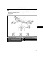
VALVE MECHANISM
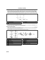
Construction
• The variable valve timing mechanism consists of a variable valve timing actuator, oil control valve (OCV), CKP
sensor, CMP sensor, and the PCM.
B
AME2211N015
.
1
2
3
4
CKP sensor
CMP sensor
PCM
Oil control valve (OCV)
5
6
7
Variable valve timing actuator
Electric signal
Hydraulic pressure
B29
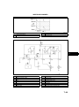
VALVE MECHANISM
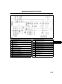
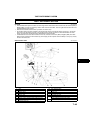
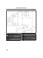
Hydraulic Pressure Flow Diagram
AME2211N016
.
1
2
3
4
5
Oil pan
Oil pump
Oil pipe
Oil filter
Oil control valve (OCV)
6
7
8
9
Oil control valve (OCV) adapter
Camshaft
Variable valve timing actuator
Cylinder block
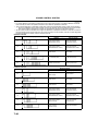
Component and function
Variable valve timing actuator
Oil control valve (OCV)
CKP sensor
CMP sensor
PCM
B30
• Continuously modifies the phases of the intake camshaft and crankshaft at the forward
end of the intake camshaft using hydraulic pressure from the oil control valve (OCV).
• Operated by current (duty signal) from the PCM. Switches the hydraulic oil passages
to the variable valve timing actuator.
• Inputs engine revolution signal to the PCM.
• Inputs cylinder identification signal to the PCM.
• Controls the oil control valve (OCV) so that optimum valve timing is obtained according
to engine operation conditions.
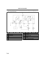
VALVE MECHANISM
Operation outline
• The variable valve timing actuator has two hydraulic chambers: a valve timing advance chamber and a valve
timing retard chamber. They are located between the integrated housing of the camshaft sprocket and the
camshaft integrated rotor. The oil pump supplies engine oil. to each chamber. Hydraulic pressure applied to
each chamber is controlled by the oil control valve (OCV) and the relative phases of the camshaft sprocket and
the camshaft are modified to obtain optimum valve timing according to engine operation conditions.
At engine start
• When the stopper pin in the variable valve timing actuator engages with the rotor, which is at the position of
maximum valve timing retard due to spring force, the camshaft sprocket and the camshaft rotate as one unit.
When the oil pump pressure rises and the stopper pin is disengaged, it becomes possible to modify the relative
angles of the camshaft sprocket and the camshaft.
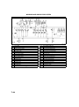
Advancing valve timing
• When the spool valve in the oil control valve (OCV) moves to the left according to the PCM signal, hydraulic
pressure, from the oil pump, feeds into the valve timing advance passage and finally to the valve timing
advance chamber in the variable valve timing actuator. Then, the rotor integrated with the camshaft rotates in
the valve timing advance direction, against the housing driven by the crankshaft, and the valve timing is
advanced.
AME2211N017
.
1
2
3
4
5
6
7
PCM
Oil control valve (OCV)
Spool valve
Oil pump
Camshaft
Variable valve timing actuator
Rotor
8
9
10
11
12
13
Housing
Oil pan
To valve timing advance chamber
Valve timing advance chamber
From valve timing retard chamber
Hydraulic pressure flow
Retarding valve timing
• When the spool valve in the oil control valve (OCV) moves to the right according to the PCM signal, hydraulic
pressure, from the oil pump, feeds into the valve timing retard passage and finally to the valve timing retard
chamber in the variable valve timing actuator. Then, the rotor integrated with the camshaft rotates in the valve
timing retard direction, against the housing driven by the crankshaft, and valve timing is retarded.
B31
B
VALVE MECHANISM
AME2211N018
.
1
2
3
4
5
6
7
PCM
Oil control valve (OCV)
Spool valve
Oil pump
Camshaft
Variable valve timing actuator
Rotor
8
9
10
11
12
13
Housing
Oil pan
To valve timing retard chamber
Valve timing retard chamber
From valve timing advance chamber
Hydraulic pressure flow
Maintaining intermediate valve timing
• The spool valve in the oil control valve (OCV) is located near the middle of the valve timing advance and retard
positions. Because of this, hydraulic pressures are maintained in both valve timing advance and retard
chambers of the variable valve timing actuator. At the same time, relative angles of the rotor and the housing
are fixed and maintained, resulting in fixed valve timing.
AME2211N019
.
1
2
3
PCM
Oil control valve (OCV)
Oil pump
B32
4
5
6
To valve timing advance chamber
To valve timing retard chamber
Hydraulic pressure flow
VALVE MECHANISM
End
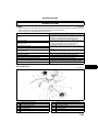
Of Sie VALVE TIMING ACTUATOR
VARIABLE
A6E221112111T05
• The variable valve timing actuator consists of the following: a housing case integrated to the camshaft
sprocket, a cover, a camshaft integrated rotor, and a stopper pin that retains the rotor and case when the
engine stops. Also, the rotor has a chip seal that seals the valve timing advance chamber and the valve timing
retard chamber.
• The cover and rotor of the variable valve timing
actuator are notched, and are used as alignment
marks when inspecting the variable valve timing
actuator.
.
1
2
3
4
5
6
7
Camshaft sprocket
Case
Rotor
Stopper pin
Tip seal
Cover
Notch
AME2224N600
End Of Sie
OIL CONTROL VALVE (OCV)
A6E221112111T06
• The oil control valve (OCV) consists of a spool valve that switches the passages for engine oil, a coil that
moves the spool valve, a plunger, and a return spring.
AME2211N012
.
1
2
Spool valve
Coil
3
4
Plunger
Return spring
End Of Sie
B33
B
LUBRICATION SYSTEM
D
ABBREVIATIONS ..................................................D-2
ABBREVIATIONS ................................................D-2
OUTLINE ................................................................D-2
OUTLINE OF CONSTRUCTION..........................D-2
FEATURES ..........................................................D-2
SPECIFICATIONS ...............................................D-2
LUBRICATION SYSTEM........................................D-3
STRUCTURAL VIEW...........................................D-3
LUBRICATION FLOW DIAGRAM........................D-4
OIL PUMP ............................................................D-7
OIL PAN ...............................................................D-9
OIL STRAINER ..................................................D-10
OIL FILTER ........................................................D-10
OIL JET VALVE .................................................D-12
D1
D
ABBREVIATIONS , OUTLINE
ABBREVIATIONS
ABBREVIATIONS
OCV
A6E330102000T01
Oil control valve
End Of Sie
OUTLINE
OUTLINE OF CONSTRUCTION
A6E330201003T01
• The lubrication system is a forced-fed type that uses a full-flow filter.
• An environment-friendly oil filter, designed so that only the internal oil filter (rather than entire assemly) need to
be replaced, has been adopted.
End Of Sie
FEATURES
A6E330201003T02
Reduced weight
• Aluminum alloy oil pan has been adopted.
• Plastic oil strainer has been adopted.
• Resin oil filter cover has been adopted.
Reduced vibration and noise
• An oil pan made from laminated damping steel has been adopted.
• The oil pan upper block is tightened with main bearing cap.
Improved lubrication and reliability
• The following have been adopted.
Trochoid gear type oil pump
Water-cooled type oil cooler (LF and L3 engine models)
Oil jet valve
End Of Sie
SPECIFICATIONS
A6E330201003T03
Item
L8
Lubrication system
Oil cooler
Oil pressure
Oil pump
(kPa
{kgf/cm2
, psi} [rpm])
Type
Relief pressure
(kPa {kgf/cm2, psi})
Oil filter
Oil capacity
(Approximate
quantity)
D2
Type
Bypass pressure
(kPa {kgf/cm2, psi})
Total (Dry engine)
(L {US qt, lmp qt})
Oil replacement
(L {US qt, lmp qt})
Oil and oil filter replacement
(L {US qt, lmp qt})
Engine
LF
Force-fed type
Water-cooled
234521 {2.395.31, 33.975.5}
[3,000]
L3
395649
{4.036.61,
57.394.1}
[3,000]
Trochoid gear type
500600
{5.096.11, 72.687.0}
Full-flow, paper element
80120 {0.91.2, 12.817.0}
4.6 {4.8, 4.0}
4.2 {4.4, 3.6}
3.9 {4.0, 3.4}
3.1 {3.3, 2.7}
4.3 {4.5, 3.8}
3.5 {3.7 ,3.1}
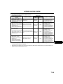
OUTLINE , LUBRICATION SYSTEM
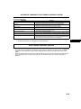
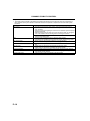
Recommended Engine oil
Item
Grade
Market
European countries
API SJ
ACEA A1 or A3
API SL
ILSAC GF-3
Viscosity (SAE)
Engine oil
Remarks
5W-30
5W-20
Mazda genuine
DEXELIA oil
Except European
countries
API SG, SH, SJ, SL
ILSAC GF-2, GF-3
40, 30, 20,
20W-20, 10W-30,
10W-40, 10W-50,
20W-40, 15W-40,
20W-50, 15W-50,
5W-20, 5W-30
End Of Sie
LUBRICATION SYSTEM
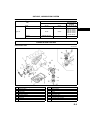
STRUCTURAL VIEW
A6E333001003T01
AME3300N001
.
1
2
3
4
5
6
7
8
9
Chain tensioner spring
Chain tensioner
Oil pump
Chain guide
Oil pump driven chain
Oil pump sprocket
Oil pan
Oil strainer
Gasket
10
11
12
13
14
15
16
17
18
Oil jet valve
Oil filter adapter
Oil pressure switch
Oil filter
Oil filter cover
Oil filter drain plug
O ring
LF and L3 engine models
Oil cooler
D3
D
LUBRICATION SYSTEM
End
Of Sie
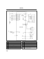
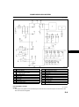
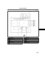
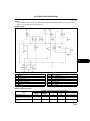
LUBRICATION
FLOW DIAGRAM
L8, LF
A6E333001003T02
AME3300N002
AME3300N003
D4
LUBRICATION SYSTEM
1
2
3
4
5
6
7
8
9
10
11
12
13
Camshaft
Cylinder head
Cylinder block
Oil jet valve
Crankshaft
Oil filter
Oil filter bypass valve
Oil pump
Oil strainer
Oil pan
Return oil
Chain tensioner
LF engine model
14
15
16
17
18
19
20
21
22
23
24
Oil cooler
To oil filter
From oil pump
Oil pressure switch
Orifice
Piston
Main bearing
Crankshaft bearing, Connecting rod bearing
Oil pressure relief valve
Elevational view
Side view
D
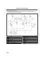
L3
AME3300N004
D5
LUBRICATION SYSTEM
AME3300N005
.
1
2
3
4
5
6
7
8
9
10
11
12
13
Camshaft
Cylinder head
Cylinder block
Oil jet valve
Crankshaft
Oil filter
Oil filter bypass valve
Oil pump
Oil strainer
Oil pan
Return oil
Chain tensioner
Oil cooler
End Of Sie
D6
14
15
16
17
18
19
20
21
22
23
24
25
Oil pressure switch
Orifice
Piston
Main bearing
Crankshaft bearing, Connecting rod bearing
Oil pressure relief valve
Elevational view
Side view
Balance shaft
Oil control valve (OCV)
Variable valve timing actuator
Oil filter (Inner engine front cover)
LUBRICATION SYSTEM
OIL PUMP
A6E333014100T01
Structure
• The oil pump is installed inside the engine front cover. The crankshaft drives the inner rotor via the oil pump
chain and oil pump sprocket.
• The oil pump consists of the oil pump sprocket, oil pump chain, oil pump chain guide, oil pump chain tensioner,
and oil pump chain tensioner spring.
.
D
AME3300N006
1
2
3
Oil pump body (with a built-in relief valve)
Oil pump chain tensioner spring
Oil pump chain tensioner
4
5
6
Oil pump chain guide
Oil pump chain
Oil pump sprocket
• An efficient and compact 5-lobe epitrochoid and 6-flank inner envelop type gear has been adopted on the oil
pump.
• The oil pump consists of the inner and outer rotors, relief valve and oil pump body.
• The oil pump cannot be disassembled. If there is an oil pump malfunction, replace it as a unit.
OIL PUMP SPEC.
ITEM
ENGINE SPEED [rpm]
Oil discharge pressure
[Oil temperature: 100°C {212°F}]
(kPa
Relief valve opening
pressure
{kgf/cm2
, psi})
L8
ENGINE
LF
1,500
129 269
{1.322.74, 18.739.0}
3,000
234521
{2.395.31, 33.975.5}
(kPa {kgf/cm2, psi})
L3
193400
{1.974.07,
27.958.0}
395 649
{4.036.61,
57.394.1}
500600
{5.096.11, 72.687.0}
D7
LUBRICATION SYSTEM
AME3300N007
.
1
2
3
4
Inner rotor
Oil in
Relief valve assembly
Outer rotor
5
6
7
Back
Oil out
Front
• A silent chain (link connecting type) has been adopted to the oil pump chain to reduce chain operation noise
when the chain and the sprocket engage.
• The engine oil in the engine front cover lubricates the oil pump chain. The wear resistance has been improved
by the nitriding processing of the pin constructing the oil pump chain.
• The durability has been improved by heating the sintering material on the oil pump sprocket inside of a furnace.
OIL PUMP DRIVEN CHAIN SPEC.
ITEM
Pitch size
Number of pitches
ENGINE
LF
L8
(mm {in})
8 {0.4}
54
L3
6.35 {0.25}
66
AME3300N008
.
D8
LUBRICATION SYSTEM
1
2
3
Timing chain
Oil pump driven chain
Pitch size
4
5
Pitch
Link
• The oil pump sprocket is heat forged from sintered metals to improve durability.
OIL PUMP SPROCKET SPEC.
ITEM
Outer diameter
Drive tooth
width
ENGINE
LF
L8
D
(mm {in})
60.78 {2.394}
L3
46.46 {1.829}
(mm {in})
6.15 {0.242}
5.7 {0.23}
.
1
2
Outer diameter
Drive tooth width
AME3300N009
End Of Sie
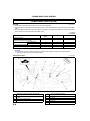
OIL PAN
A6E333010040T01
Structure
• An aluminum alloy oil pan has been adopted for weight reduction. A silicon sealant with excellent sealing
qualities has been also adopted.
• Oil pan baffle plates have been adopted inside the oil pan to stabilize engine oil diffusion by crankshaft rotation
and oil level when the vehicle rolls.
AME3300N010
.
1
Oil pan baffle plate
End Of Sie
D9
LUBRICATION SYSTEM
OIL STRAINER
A6E333014700T01
Structure
• A plastic oil strainer with a resin filter in the middle of the strainer has been adopted for weight reduction.
AME3300N011
.
1
2
3
4
Appearance figure
Oil supply mouth
Oil strainer
Oil pump attachment side
5
6
7
A - A sectional view
Oil strainer
Filter
End Of Sie
OIL FILTER
A6E333014300T01
Structure
• The oil filter is attached to the right side of the oil level gage (oil pan side) on cylinder block.
• The oil filter adapter has been adopted for weight reduction. The oil pressure switch is installed on the oil filter
adapter.
• A resin oil filter has been adopted for weight reduction. A drain has been installed on the bottom of the oil filter
replacement service ability.
• An environment-friendly oil filter, designed so that only the internal oil filter (rather than entire assembly) need
to be replaced, has been adopted. The replaceable oil filter is made of a material that can be completely
incinerated.
• A water-cooled oil cooler has been adopted to reduce the engine oil degradation. Also, the exclusive use oil
filter adapter has been adapted for the oil cooler. (LF and L3 engine models)
D10
LUBRICATION SYSTEM
OIL FILTER SPEC.
ITEM
Outer diameter
Height
ENGINE
LF
L8
(mm {in})
(mm {in})
6769 {2.42.7}
73.575.5 {2.892.97}
L3
65.265.8 {2.572.59}
72.674.4 {2.862.92}
D
AME3300N012
.
1
2
3
4
5
6
Cylinder block
Oil level gage
Gasket
Oil filter
Oil filter cover
Oil filter adapter
7
8
9
10
11
12
Oil pressure switch
O-ring
Oil cooler
To water outlet case
To thermostat
LF and L3 engine models
AME3300N013
.
1
2
3
4
5
Oil filter
Oil filter cover
Relief valve
Oil filter
Normal
6
7
8
9
Relief
Spring
Oil pressure
Oil passage
D11
LUBRICATION SYSTEM
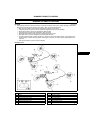
OIL JET VALVE
End Of Sie
A6E333010730T01
Structure
• The oil jet valves are installed in the cylinder block (in the main journal). The piston cooling efficiency by oil
injected from the nozzles has been improved by the attachment direction of the oil jet valves which are pointed
toward the back surface of each piston.
• The oil jet valves have been designed to maintain optimum oil pressure in the engine by controlling the oil
injection of the oil according to the oil pressure on the oil jet valve.
AME3300N014
.
1
2
Oil jet valve
Cylinder block
D12
3
Crankshaft
LUBRICATION SYSTEM
Operation
• Oil pressure applied to the check-ball in the oil jet valve opens and closes the oil passage way to the nozzle
and controls oil injection start and stop.
• Oil pressure greater than the specified value applied to the check-ball in the oil jet valve opens the oil passage
to the spring-pressed nozzle, starting injection. Conversely, oil pressure less than the specified value applied to
the check-ball blocks the jet valve by spring force, stopping injection.
D
AME3300N015
.
1
2
3
Nozzle
Oil jet valve body
Spring
4
5
6
Oil
Oil passage
Check ball
End Of Sie
D13
COOLING SYSTEM
E
ABBREVIATIONS ..................................................E-2
ABBREVIATIONS ................................................ E-2
OUTLINE ................................................................ E-2
OUTLINE OF CONSTRUCTION.......................... E-2
FEATURES .......................................................... E-2
SPECIFICATIONS ............................................... E-2
COOLING SYSTEM................................................ E-3
STRUCTURAL VIEW...........................................E-3
COOLING FLOW DIAGRAM ............................... E-4
RADIATOR........................................................... E-5
COOLING FAN .................................................... E-5
RADIATOR COWLING, COOLANT RESERVOIR
TANK................................................................. E-6
THERMOSTAT .................................................... E-6
WATER PUMP..................................................... E-7
E1
E
ABBREVIATIONS , OUTLINE
ABBREVIATIONS
ABBREVIATIONS
ATF
ATX
A6E360102000T01
Automatic transaxle fluid
Automatic transaxle
End Of Sie
OUTLINE
OUTLINE OF CONSTRUCTION
• L8, LF and L3 engine models are water cooled by forced circulation cooling systems.
A6E360201004T01
End Of Sie
FEATURES
Reduced weight and size
• Cross-flow type radiator with radiator tanks made of plastic and the core made of aluminum.
• Stainless steel thermostat body is built in the plastic thermostat case
• Built-in type water pump
Reduce engine noise and vibration
• The cooling fan is a thermo modulator system type.
• Electric cooling fan has been adopted.
Improved reliability
• The following have been adopted.
Thermostat of highly durable wax type.
Water pump that is built into cylinder block
A6E360201004T02
End Of Sie
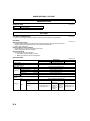
SPECIFICATIONS
A6E360201004T03
Item
Cooling system
Coolant capacity
(L {US qt, lmp qt})
(Approximate quantity)
Water pump Type
Type
Opening temperature
(°C {°F})
Thermostat
Full-open temperature
(°C {°F})
Full-open lift
(mm {in})
Radiator
Type
Cap valve opening
(kPa {kgf/cm2, psi})
pressure
Type
Outer
(mm {in})
diameter
Cooling fan
End Of Sie
E2
Blade
Quantity
Engine type
LF
Water-cooled, Electromotive
L8
L3
7.5 {7.9, 6.6}
Centrifugal, V-ribbed belt-driven
Wax
80.084.0 {176183.2}
97 {206.6}
More then 8.0 {0.31} min.
Corrugated fin
112.8142.2 {1.151.45, 16.420.6}
Thermo-modulated, Electromotive
300 {11.8}
Cooling fan No.1: 5
Cooling fan No.2: 7
300 {11.8}
320 {12.6}
(Except for
(For Israel)
Israel)
Cooling fan
Cooling fan
Cooling fan No.1: 7
No.1: 7
No.1: 5
Cooling fan No.2: 5
Cooling fan
Cooling fan
No.2: 5
No.2: 7
COOLING SYSTEM
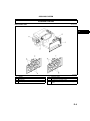
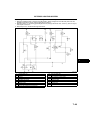
COOLING SYSTEM
STRUCTURAL VIEW
A6E363001004T02
E
AME3602N001
.
1
2
3
4
Radiator
Radiator cap
Thermostat
Water pump
5
6
7
8
Cooling fan blade
Cooling fan motor No.1,Cooling fan motor No.2
For Israel and L3 engine model
LF engine model except for Israel and L8 engine
model
End Of Sie
E3
COOLING SYSTEM
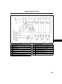
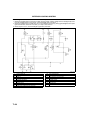
COOLING FLOW DIAGRAM
A6E363001004T03
AME3602N002
.
1
2
3
4
5
Heater
Radiator
Coolant reservoir tank
Thermostat
Water pump
End Of Sie
E4
6
7
8
9
Cylinder head
Cylinder block
Oil cooler
LF and L3 engine models
COOLING SYSTEM
RADIATOR
A6E363015200T01
Structure
• A cross-flow radiator with corrugated fins is used for improved cooling.
• The radiator tanks are made of plastic and the core is made of aluminum.
• Four rubber-insulated mounting brackets are utilized to decrease vibration.
• The radiator has an ATF cooler in the radiator tank. (ATX)
• A small pressuring type cap has been adopted for
the radiator cap.
E
AME3602N003
End Of Sie
COOLING FAN
A6E363015140T01
Structure
• Electric cooling fans No.1 and No.2, operated according to a fan control signal from the PCM, have been
adopted. Due to this, engine noise is reduced and rapid warming-up is possible.
• A cooling fan No.1 and No.2 is attached to the radiator cowling.
Cooling fan, fan motor specs:
ITEM
Cooling fan No.1
Cooling fan No.2
L8
Number of
Blade
Motor
output
Number of
Blade
Motor
output
ENGINE
LF
For Israel: 7
Except for
Israel: 5
L3
(sheet)
5
7
(W)
80
80-120
70
(sheet)
7
For Israel: 5
Except for
Israel: 7
5
(W)
80
80-120
120
End Of Sie
E5
COOLING SYSTEM
RADIATOR COWLING, COOLANT RESERVOIR TANK
A6E363015140T02
Structure
• A radiator cowling is made of plastic for the weight reduction.
• A coolant reservoir tank can be removed from the radiator cowling. (For Israel and L3 engine models)
• A coolant reservoir tank can not be removed from the radiator cowling. (LF engine models except for Israel and
L8 engine models)
.
AME3602N004
1
2
3
To radiator
Coolant reservoir tank
Cooling fan motor No.1
4
5
6
Cooling fan motor No.2
LF engine model except for Israel and L8 engine
models
For Israel and L3 engine models
End Of Sie
THERMOSTAT
A6E363015171T01
Structure
• A wax-type thermostat with a jiggle-pin has been adopted.
• The plastic thermostat case has a built-in stainless steel thermostat body with excellent corrosion resistance.
• When the engine coolant temperature is below 75.0°C {167°F}, the thermostat stops the circulation of radiator
coolant from the radiator for improved engine warming. When the engine coolant temperature is between
80.0°C {176°F} to 84.0 °C {183.2°F}, the thermostat begins opening the valve and engine coolant flows from
the radiator to stabilize engine coolant temperature.
.
AME3602N005
1
2
3
4
Engine side
Radiator side
Water pump
Thermostat body
End Of Sie
E6
5
6
7
Thermostat case
Oil cooler (LF and L3 engine models)
Heater hose (L8 engine model)
Lower radiator hose
COOLING SYSTEM
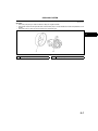
WATER PUMP
A6E363015010T01
Structure
• The water pump body is made of aluminum alloy for weight reduction.
• The impeller is built into the cylinder block and the water pump is not seviceable and must be replaced as a unit
if faulty.
• The water pump is driven by the front drive belt. (sirpentain type)
•
E
AME3602N006
1
.
Water pump pulley
2
Water pump body
End Of Sie
E7
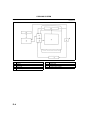
FUEL AND EMISSION CONTROL SYSTEMS
F
ABBREVIATIONS .................................................. F-2
ABBREVIATIONS ................................................ F-2
OUTLINE ................................................................ F-3
OUTLINE OF CONSTRUCTION ......................... F-3
FEATURES .......................................................... F-3
SPECIFICATIONS ............................................... F-3
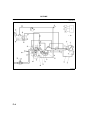
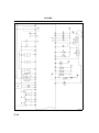
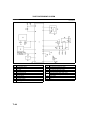
CONTROL SYSTEM DIAGRAM .......................... F-4
CONTROL SYSTEM WIRING DIAGRAM............ F-6
INTAKE-AIR SYSTEM.......................................... F-13
INTAKE-AIR SYSTEM OUTLINE ...................... F-13
INTAKE-AIR SYSTEM STRUCTURAL VIEW.... F-14
VARIABLE AIR DUCT (VAD) SYSTEM
OUTLINE (L3) ................................................. F-14
VARIABLE AIR DUCT (VAD) SHUTTER VALVE
DESCRIPTION (L3) ........................................ F-15
VARIABLE AIR DUCT (VAD) SOLENOID VALVE
DESCRIPTION (L3) ........................................ F-16
VARIABLE AIR DUCT (VAD) CHECK VALVE
(ONE-WAY) DESCRIPTION (L3) ................... F-16
FUEL SYSTEM ..................................................... F-17
FUEL SYSTEM OUTLINE ................................. F-17
FUEL SYSTEM STRUCTURAL VEW................ F-18
FUEL PUMP UNIT DESCRIPTION ................... F-19
EXHAUST SYSTEM ............................................. F-20
EXHAUST SYSTEM OUTLINE.......................... F-20
EXHAUST SYSTEM STRUCTURAL VIEW ....... F-21
EMISSION SYSTEM............................................. F-22
OUTLINE .......................................................... F-22
EMISSION SYSTEM STRUCTURAL VIEW ...... F-23
PULSATION REDUCE CHAMBER
DESCRIPTION ............................................... F-24
THREE-WAY CATALYTIC CONVERTER (TWC)
DESCRIPTION ............................................... F-24
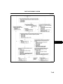
CONTROL SYSTEM............................................. F-25
OUTLINE ........................................................... F-25
STRUCTURAL VIEW......................................... F-28
BLOCK DIAGRAM ............................................. F-30
CONTROL DEVICES AND CONTROL
RELATIONSHIP CHART ................................ F-32
CAMSHAFT POSITION (CMP) SENSOR.......... F-34
CRANKSHAFT POSITION (CKP) SENSOR...... F-34
IDLE AIR CONTROL (IAC) ................................ F-35
VARIABLE AIR DUCT (VAD) CONTROL .......... F-35
VARIABLE INTAKE-AIR CONTROL SYSTEM .. F-35
VARIABLE TUMBLE CONTROL SYSTEM
(VTCS) ............................................................ F-35
VARIABLE VALVE TIMING CONTROL............. F-36
FUEL INJECTION CONTROL ........................... F-36
A/C CUT-OFF CONTROL.................................. F-36
ELECTRIC FAN CONTROL .............................. F-37
CONTROLLER AREA NETWORK (CAN) ......... F-38
ON-BOARD DIAGNOSTIC................................... F-40
OUTLINE ........................................................... F-40
CONTROL DEVICES AND MONITORING
SYSTEM RELATIONSHIP CHART ................ F-40
DIAGNOSTIC TEST MODE............................... F-41
DTC.................................................................... F-44
PID/DATA MONITOR AND RECORD ............... F-50
SIMULATION TEST ........................................... F-52
KOEO/KOER SELF-TEST ................................. F-52
F
F1
ABBREVIATIONS
ABBREVIATIONS
ABBREVIATIONS
AAS
CAN
DC
FFD
KOEO
KOER
OCV
PC
PID
TCS
VAD
VIS
VLIM
VTCS
End Of Sie
F2
Air adjust screw
Controller area network
Drive cycle
Freeze frame data
Key on, engine off
Key on, engine running
Oil control valve
Pending code
Parameter identification
Traction control system
Variable air duct
Variable intake-air system
Variable length intake manifold
Variable tumble control system
A6E390118881T01
OUTLINE
OUTLINE
OUTLINE OF CONSTRUCTION
A6E390218881T01
• The Mazda6 (GG) has been equipped with the new engine (L series). The features of the L series engines are
as follows.
End Of Sie
FEATURES
A6E390218881T02
System simplification
• Controller area network has been adopted.
• Mechanical returnless fuel system has been adopted.
Improved engine performance
• Variable air duct (VAD) control system has been adopted to improve engine performance at high engine speed.
(L3 engine)
• Variable valve timing control system has been adopted to improve engine performance. (L3 engine)
• Variable intake-air system (VIS) has been adopted to improve engine torque characteristics and combustion
efficiency. (L3 engine)
Improved emission performance
• Variable valve timing control system has been adopted. (L3 engine)
• Variable tumble control system (VTCS) has been adopted.
• New fuel injection timing control has been adopted.
• Manifold absolute pressure correction has been adopted to IAC control and fuel injection control.
Weight reduction
• Resin fuel tank has been adopted.
Improved serviceability
• Nonadjustable ignition timing has been adopted.
• Nonadjustable IAC has been adopted.
• Quick release connectors have been adopted on all joints of fuel lines.
• KOEO/KOER self-test function has been adopted.
• Pending code storage process has been changed.
• MIL illumination conditions for the second drive cycle type have been changed.
End Of Sie
SPECIFICATIONS
A6E390218881T03
Item
Air cleaner element
IAC valve
Fuel injector
Pressure regulator
Fuel tank
Fuel
Catalyst
EGR control
Evaporative emission control
system
PCV system
Type
Type
Type
Type of fuel delivery
Type of drive
Regulating pressure
(kPa {kgf/cm2, psi})
Capacity
(L {US qt, lmp qt})
Specification
Type
Type
L8, LF, L3
Paper element (oil permeated)
Duty control
Hi-ohmic
Top-feed
Voltage
440 {4.5, 64}
64 {68, 56}
Unleaded (RON 95 or above)
TWC (monolithic)
Stepping motor type
Type
Canister type
Type
Closed type
End Of Sie
F3
F
OUTLINE
CONTROL SYSTEM DIAGRAM
A6E390218881T04
A6E3902T000
.
F4
OUTLINE
1
2
3
4*
5
6
7*
8*
9*
10*
11
12
13
14
15*
16
17*
18*
19
20
*
PCM
Ignition coil
Generator
VAD shutter valve
Air cleaner
MAF sensor
VAD shutter valve actuator
VAD control solenoid valve
Vacuum chamber
VAD check valve (one-way)
IAC
Purge solenoid valve
TP sensor
MAP sensor
VIS control solenoid valve
Variable tumble control solenoid valve
VIS shutter valve actuator
VIS shutter valve
VTCS shutter valve actuator
VTCS shutter valve
21
22*
23
24
25
26
27
28
29
30
31
32
33
34
35
36
37
38
39
40
Fuel injector
OCV
CMP sensor
EGR valve
Knock sensor
ECT sensor
PCV valve
CKP sensor
Heated oxygen sensor (front)
Heated oxygen sensor (rear)
Charcoal canister
Check valve (two-way)
Pressure regulator
Fuel filter (high pressure)
Fuel pump
Fuel filter (low pressure)
Fuel tank
Rollover valve
Pulsation damper
To PCM
F
: Equipped for L3 engine model
End Of Sie
F5
OUTLINE
CONTROL SYSTEM WIRING DIAGRAM
With Immobilizer System
A6E390218881T05
A6E3940T901
.
F6
OUTLINE
1
2
3
4
5
6
7
8
9
10
11
12
13
14
15
16
17
Heated oxygen sensor (front)
Heated oxygen sensor (rear)
TP sensor
MAP sensor
BARO sensor
ECT sensor
MAF/IAT sensor
IAT sensor
MAF sensor
Controller area network (CAN)
Knock sensor
CKP sensor
CMP sensor
Fuel injector No.1
Fuel injector No.2
Fuel injector No.3
Fuel injector No.4
18
19
20
21
22
23
24
25
26
27
28
29
30
31
32
33
IAC
Oxygen sensor heater (front)
Oxygen sensor heater (rear)
A/C relay
Cooling fan relay
Cooling fan relay
Cooling fan relay
Cooling fan relay
Fuel pump relay
Coil
Security light
Ignition switch
Main relay
L8, LF (Intensely hot area) and L3 engine models
ATX model
MTX model
F7
F
OUTLINE
A6E3940T903
.
F8
OUTLINE
34
35
36
37
38
39
40
41
42
43
44
45
46
47
48
Generator
Refrigerant pressure switch (middle)
PSP switch
Blower motor
Refrigerant pressure switch (high and low)
A/C switch
Brake switch
Neutral switch
Clutch switch
TR switch
Turbine speed sensor
HOLD switch
TFT sensor
Oil pressure switch
VSS
49
50
51
52
53
54
55
56
57
58
59
60
61
62
Ignition coil
Generator
Purge solenoid valve
VAD control solenoid valve
EGR valve
Variable tumble control solenoid valve
VIS control solenoid valve
OCV
Valve body
Brake light
L8, LF (Intensely hot area) and L3 engine models
MTX model
ATX model
L3 engine model
F9
F
OUTLINE
Without Immobilizer System
A6E3940T902
.
F10
OUTLINE
1
2
3
4
5
6
7
8
9
10
11
12
13
14
15
Heated oxygen sensor (front)
Heated oxygen sensor (rear)
TP sensor
MAP sensor
BARO sensor
ECT sensor
MAF/IAT sensor
IAT sensor
MAF sensor
Controller area network (CAN)
Knock sensor
CKP sensor
CMP sensor
Fuel injector No.1
Fuel injector No.2
16
17
18
19
20
21
22
23
24
25
26
27
28
29
30
Fuel injector No.3
Fuel injector No.4
IAC
Oxygen sensor heater (front)
Oxygen sensor heater (rear)
A/C relay
Cooling fan relay
Cooling fan relay
Cooling fan relay
Cooling fan relay
Fuel pump relay
Ignition switch
Main relay
L8, LF (Intensely hot area) and L3 engine models
ATX model
F11
F
OUTLINE
A6E3940T904
.
F12
OUTLINE, INTAKE-AIR SYSTEM
31
32
33
34
35
36
37
38
39
40
41
42
43
44
45
Generator
Refrigerant pressure switch (middle)
PSP switch
Blower motor
Refrigerant pressure switch (high and low)
A/C switch
Brake switch
Brake light
Neutral switch
Clutch switch
TR switch
Input/turbine speed sensor
HOLD switch
TFT sensor
Oil pressure switch
46
47
48
49
50
51
52
53
54
55
56
57
58
59
VSS
Ignition coil
Generator
Purge solenoid valve
VAD control solenoid valve
EGR valve
Variable tumble control solenoid valve
VIS control solenoid valve
OCV
Valve body
L8, LF (Intensely hot area) and L3 engine models
MTX model
ATX model
L3 engine model
End Of Sie
INTAKE-AIR SYSTEM
INTAKE-AIR SYSTEM OUTLINE
A6E391013000T01
• The function, structure and operation of each part in the intake-air system of the Mazda6 (GG) L3, LF, and L8
engine models are essentially carried over from the current 323 (BJ) FS engine models, except for the
following:
A non AAS type throttle body has been adopted to improved serviceability.
A resin intake manifold has been adopted to reduce weight.
The variable air duct (VAD) system has been adopted to improved the engine performance.
Variable intake-air system (VIS) has been adopted. Same function as VICS of current 323 (BJ) FS engine
models.
×: Applied
: Not applied
Item
L3
Mazda6 (GG)
LF
L8
Resonance chamber
×
Air cleaner
×
Throttle body
×
IAC valve
×
Intake manifold
×
Dynamic chamber
×
VIS
×
VTCS
VAD system
×
×
×
Current 323
(BJ) FS
Remark for new model
Same function as current 323 (BJ) FS
engine models
Same function as current 323 (BJ) FS
engine models
Same function as current 323 (BJ) FS
engine models
AAS has been eliminated due to
automatic adjustment of idle speed
Same function as current 323 (BJ) FS
engine models
Same function as current 323 (BJ) FS
engine models
Same function as current 323 (BJ) FS
engine models
Same function as VICS of current 323
(BJ) FS engine models
Same function as current MX-5 (NB)
BP engine models
Newly adopted
End Of Sie
F13
F
INTAKE-AIR SYSTEM
INTAKE-AIR SYSTEM STRUCTURAL VIEW
A6E391013000T02
A6E3910W036
.
1
2
3
4
5
6
7
8
Air cleaner
IAC valve
Resonance chamber
VIS control solenoid valve (L3)
Variable tumble control solenoid valve
L8, LF engine models
Intake manifold
VIS shutter valve actuator (L3)
9
10
11
12
13
14
15
16
VTCS shutter valve actuator
VAD check valve (one-way) (L3)
Accelerator pedal (R.H.D.)
Accelerator cable (R.H.D.)
Accelerator pedal (L.H.D.)
Accelerator cable (L.H.D.)
VAD shutter valve (L3)
VAD control solenoid valve (L3)
End Of Sie
VARIABLE AIR DUCT (VAD) SYSTEM OUTLINE (L3)
A6E391013000T03
Outline
• The VAD control system opens the VAD shutter valve in the air cleaner only at high engine speeds not
decrease at high engine speeds due to insufficient mass airflow amount.
Structure
• The VAD system is composed of VAD shutter valve, VAD control solenoid valve, VAD vacuum chamber, VAD
check valve (one-way).
F14
INTAKE-AIR SYSTEM
F
A6E3910W029
.
1
2
VAD shutter valve
VAD control solenoid valve
3
4
VAD vacuum chamber
VAD check valve (one-way)
End Of Sie
VARIABLE AIR DUCT (VAD) SHUTTER VALVE DESCRIPTION (L3)
Function
• Opens and closes the shutter valves.
A6E391013000T04
Structure
• The VAD shutter valve actuator is composed of a rod, diaphragm chamber, and spring.
Operation
• Normally, the rod is pushed by the force of the spring, opening the shutter valve. When intake manifold vacuum
is applied to the diaphragm chamber, the rod is pulled, closing the shutter valve.
A6E3910W027
.
1
2
3
Shutter valve open
Shutter valve close
VAD shutter valve actuator
4
5
6
Rod
VAD shutter valve
Intake manifold vacuum
End Of Sie
F15
INTAKE-AIR SYSTEM
VARIABLE AIR DUCT (VAD) SOLENOID VALVE DESCRIPTION (L3)
Function
• Switches the intake manifold vacuum passage between the intake manifold and the actuator.
A6E391013000T05
Structure
• Composed of a solenoid coil, spring, plunger, and filter.
Operation
Energized
• The plunger is pulled back to open the air passage between the A and B ports, which applies the atmosphere
to the VAD shutter valve actuator.
De-energized
• The plunger is returned forward to open the air passage between the B and C ports, which applies the intake
manifold vacuum VAD shutter valve actuator.
A6E3910W026
.
1
2
3
4
Energized
De-energized
Port A (to atmosphere)
Port B (to actuator)
5
6
7
8
Port C (to intake manifold)
Coil
Plunger
Spring
End Of Sie
VARIABLE AIR DUCT (VAD) CHECK VALVE (ONE-WAY) DESCRIPTION (L3)
Function
• The VAD check valve (one-way) maintain the vacuum in the VAD vacuum chamber.
A6E391013000T06
Structure
• The VAD check valve (one-way) is composed of a valve.
Operation
• The VAD check valve (one-way) allows air flow only from VAD vacuum chamber to intake manifold.
A6E3910W035
.
1
2
3
Check valve
Green
White
End Of Sie
F16
4
5
Intake manifold
VAD vacuum chamber
FUEL SYSTEM
FUEL SYSTEM
FUEL SYSTEM OUTLINE
A6E391201006T01
• The function, structure and operation of each part in the fuel system of the Mazda6 (GG) L3 engine model are
the same as those of the 323 (BJ) FS engine models except for the following:
Mechanical returnless fuel system has been adopted.
× : Applied
Item
Fuel tank
Fuel pump unit
(Built-in fuel filter
(high-and low-pressure))
Quick release connector
(fuel distributor side)
Quick release connector
(fuel tank side)
Quick release connector
(engine room side)
L3
Mazda6 (GG)
LF
L8
323 (BJ) FS
Remark for new model
×
Same as current 323 (BJ) FS
engine models
×
New part adopted
×
×
Same as current 323 (BJ) FS
engine models
(fuel distributor side)
×
Pulsation dumper
×
Pressure regulator
×
Fuel injector
×
Nonreturn valve
×
Same as current 323 (BJ) FS
engine models
Integrated pressure regulator with
the fuel pump unit
Same as current 323 (BJ) FS
engine models
Same as current 323 (BJ) FS
engine models
End Of Sie
F17
F
FUEL SYSTEM
FUEL SYSTEM STRUCTURAL VEW
Engine Room Side
A6E391201006T02
A6E3912W048
Fuel tank side
A6E3912W049
.
F18
FUEL SYSTEM
1
2
3
4
5
Fuel tank
Nonreturn valve
Fuel pump unit
Fuel injector
Pulsation damper
6
7
8
9
Fuel pump relay
Check connector
Quick release connector
Fuel filler cap
End Of Sie
FUEL PUMP UNIT DESCRIPTION
A6E391213350T01
Note
• It is normal to hear the fuel pump operating when the ignition switch is turned to the ON position.
F
Function
• Due to the adoption of the mechanical returnless fuel system.
• The fuel pump unit, except for the fuel gauge sender unit, is integrated for confidentiality protection.
• To prevent decreased engine output from a lack of fuel supply when the vehicle is turning, the fuel pump has
been designed so the fuel supply always remains constant in the fuel reservoir cup.
• Fuel stored in the fuel reservoir cup is supplied from two lines: the check valve (one-way) and the jet pump.
Structure
A6E3912W024
F19
FUEL SYSTEM, EXHAUST SYSTEM
Fuel flow
A6E3912W035
.
1
2
3
4
5
6
7
Fuel pump unit
Fuel gauge sender unit
Fuel pump
Fuel filter (high-pressure)
Fuel filter (low-pressure)
Fuel reservoir cup
Pressure regulator
8
9
10
11
12
13
Fuel jet pump
One-way valve
Main fuel flow
Return fuel flow
To fuel distributor
Fuel tank
End Of Sie
EXHAUST SYSTEM
EXHAUST SYSTEM OUTLINE
A6E391440000T01
Features
• The exhaust manifold is located behind the engine.
• This layout allows for shorter exhaust pipes and improved exhaust efficiency. Moreover, due to the shorter distance to the catalytic
converter, temperature decrease of exhaust emission is prevented and catalyst is more efficient.
• Temperature decrease of exhaust emission is further prevented with double layer exhaust manifold pipes.
F20
EXHAUST SYSTEM
End
Of SieSYSTEM STRUCTURAL VIEW
EXHAUST
A6E391440000T02
F
A6E3914W001
.
1
2
3
4
Main silencer
Middle pipe
TWC
Exhaust manifold
5
6
7
HO2S (front)
HO2S (rear)
L3 engine model
F21
EMISSION SYSTEM
End Of Sie
EMISSION SYSTEM
OUTLINE
A6E391601007T01
• The function, structure and operation of each part in the emission system of the Mazda6 (GG) L3, LF, and L8
engine models are the same as those of the MPV (LW) FS engine models, except for the following:
Charcoal canister has been changed.
The pulsation reduce chamber has been adopted. (R.H.D.)
× : Applied
: Not applied
Item
Mazda6 (GG)
L3
LF
L8
Rollover valve
×
Charcoal canister
×
Evaporative gas check
valve (one-way)
×
Purge solenoid valve
×
PCV valve
×
TWC
×
EGR valve
×
Pulsation reduce chamber
(R.H.D.)
End Of Sie
F22
×
Current
MPV (LW)
FS
Remark for new model
Same as current MPV (LW) FS engine
models
Same as current MPV (LW) FS engine
models
Same as current MPV (LW) FS engine
models
Same as current MPV (LW) FS engine
models
Same function and operation as current
MPV (LW) FS engine models
Same function as current MPV (LW) FS
engine models
Same function and operation as current
MPV (LW) FS engine models
Newly adopted
EMISSION SYSTEM
EMISSION SYSTEM STRUCTURAL VIEW
Engine room side
A6E391601007T02
F
A6E3916W024
Fuel tank side
A6E3916W025
.
F23
EMISSION SYSTEM
1
2
3
4
5
6
EGR valve
Purge solenoid valve
Evaporative gas check valve (one-way) (L.H.D.)
PCV valve
Ventilation hose
TWC
7
8
9
10
11
Charcoal canister (L.H.D.)
Charcoal canister (R.H.D.)
Pulsation reduce chamber (R.H.D.)
Rollover valve
Check valve (two-way)
End Of Sie
PULSATION REDUCE CHAMBER DESCRIPTION
• A pulsation reduce chamber has been adopted
between the purge solenoid valve and the
charcoal canister to eliminate pulsation that
occurs during the purge solenoid valve operation,
preventing the pulsation from being transmitted to
the charcoal canister.
A6E391601007T03
.
1
2
3
Pulsation reduce chamber
To purge solenoid valve
To charcoal canister
A6E3916W022
End Of Sie
THREE-WAY CATALYTIC CONVERTER (TWC) DESCRIPTION
A6E391620500T01
Features
• Due to the shorter distance to the catalytic converter, temperature decrease of exhaust emission is prevented
and catalyst is more efficient.
• Temperature decrease of exhaust emission is further prevented with double layered exhaust manifold pipes.
End Of Sie
F24
CONTROL SYSTEM
CONTROL SYSTEM
OUTLINE
A6E394018881T01
• The construction and operation of the Mazda6 (GG) is essentially carried over from that of the current MPV
(LW) FS engine model, except for the following.
New Devices
• MAP sensor which monitoring the intake manifold absolute pressure is the same function as BARO sensor.
Similar Devices
CKP sensor
• Output wave form is different.
CMP sensor
• Output wave form is different.
F
New Systems
Variable air duct control
• To improve the engine performance at high engine speed.
Controller area network (CAN)
• To simplify the system.
Similar Systems
Idle air control (IAC)
• Same function as MPV (LW) FS engine model except for the followings.
Adopt the MAP factor to the feedback correction to improve the precise control.
Idle speed is different to match the vehicle characteristics.
Variable intake-air system (VIS)
• Same function as VICS but operation condition is different to match the vehicle characteristics.
Variable tumble control system (VTCS)
• Same function as MX-5 (NB) but operation condition is different to match the vehicle characteristics.
Variable valve timing control system
• Same function as MX-5 (NB) but operation condition is different to match the vehicle characteristics.
Fuel injection control
• Same function as MPV (LW) FS engine model except for the following.
Adopt the BARO correction to improve the precise control.
Adopt the Rear HO2S feedback correction to improve the emission performance.
Electronic spark advance (ESA) control
• Same control as 626 (GF) FS engine model
Purge control
• Adopt the BARO correction to improve the emission performance
Heated oxygen sensor heater control
• Same control as 323 (BJ) FS engine model
A/C cut-off control
• Operation condition is different to match the vehicle characteristics.
Immobilizer system
• Same function as MPV (LW) FS engine model however it equipped into PCM to simplify the system.
F25
CONTROL SYSTEM
Input Device
×:Applied
: Not applied
Item
Signal
MAF/IAT sensor
TP sensor
MAF and IAT
TP
MAP sensor
MAP
ECT sensor
ECT
Cylinder
identification
Engine
revolution
Knocking
Oxygen
concentration
BARO
Load/no load
distinction
Load/no load
distinction
Brake pedal
condition
P/S oil pump
load condition
Vehicle speed
A/C operational
CMP sensor
CKP sensor
Knock sensor
HO2S (Front, Rear)
BARO sensor
Neutral switch
Clutch switch
Brake switch
PSP switch
VSS
A/C switch, refrigerant
pressure switch (high,
low pressure)
Refrigerant pressure
switch (middle pressure)
Battery
Generation voltage
(Generator terminal P)
Immobilizer unit
F26
A/C compressor
load
Battery voltage
Generation
voltage
Immobilizer
system
communication
Current
MPV (LW)
FS
Mazda6
(GG)
×
×
Remark for new model
×
Same as 323 (BJ) ZM engine model
Same function as MPV (LW) FS engine model
Same function as BARO sensor of MPV (LW) FS
engine model
Same function as MPV (LW) FS engine model
Same function as MPV (LW) FS engine model
Output wave form is different.
Same function as MPV (LW) FS engine model
Output wave form is different.
Same function as MPV (LW) FS engine model
×
Same function as MPV (LW) FS engine model
×
Same as MPV (LW) FS engine model
×
Same as MPV (LW) FS engine model
×
Same as MPV (LW) FS engine model
×
Same as MPV (LW) FS engine model
×
Same function as MPV (LW) FS engine model
×
Same as MPV (LW) FS engine model
×
Same as MPV (LW) FS engine model
×
Same as MPV (LW) FS engine model
×
Same as MPV (LW) FS engine model
×
Same as MPV (LW) FS engine model
×
Same function as MPV (LW) FS engine model
×
×
×
×
CONTROL SYSTEM
Output Device
×:Applied
: Not applied
Item
Signal
Mazda6
(GG)
Current
MPV (LW)
FS
IAC valve
IAC
×
VIS solenoid valve
VIS
×
VTCS solenoid valve
VTCS
×
Oil control valve (OCV)
Variable valve
timing control
×
Fuel injector
Fuel injection
control
×
Remark for new model
Same function as MPV (LW) FS engine model
Idle speed is different to match vehicle characteristics.
Same function as VICS of MPV (LW) FS engine model
Operation condition is different.
Same function as MX-5 (NB)
Operation condition is different.
Same function as MX-5 (NB)
Operation condition is different.
Same function as MPV (LW) FS engine model
Fuel injection timing is different.
Add BARO correction
Add Rear HO2S feedback correction
Ignition coil
EGR valve
Fuel pump
control
ESA control
EGR control
Purge solenoid valve
Purge control
×
O2S heater
control
×
Same as 323 (BJ) FS engine model
×
Same as MPV (LW) FS engine model
Fuel pump relay
Heated oxygen sensor
heater
(Front, rear)
Field coil
(Generator terminal D)
Cooling fan relay
A/C relay
Controller area network
(CAN)
Generator
control
Electric fan
control
A/C cut-off
control
Information
function
×
Same as MPV (LW) FS engine model
×
×
Same as 626 (GF) FS engine model
Same as MPV (LW) FS engine model
Same function as MPV (LW) FS engine model
Add BARO correction
×
Same function as MPV (LW) FS engine model
Operation condition is different.
×
×
New system adopted
New system adopted
End Of Sie
F27
F
CONTROL SYSTEM
STRUCTURAL VIEW
A6E394018881T02
A6E3940T000
F28
CONTROL SYSTEM
.
1
2
3
4
5
6
7
8
9
10
11
12
MAF/IAT sensor
TP sensor
MAP sensor
CMP sensor
CKP sensor
ECT sensor
Knock sensor
HO2S (front, rear)
P/S pressure switch
Clutch switch
Neutral switch
TR switch
13
14
15
16
17
18
19
20
21
22
23
24
Brake switch
VAD control solenoid valve
IAC valve
VIC solenoid valve
VTCS solenoid valve
OCV
Fuel injector
Ignition coil
Purge valve
EGR valve
BARO sensor
LF and L8 engine models
F
End Of Sie
F29
CONTROL SYSTEM
BLOCK DIAGRAM
A6E394018881T03
A6E3940T001
.
F30
CONTROL SYSTEM
1
2
3
4
5
6
7
8
9
10
11
12
13
14
15
16
17
18
19
20
21
22
23
MAF/IAT sensor
TP sensor
MAP sensor
CMP sensor
CKP sensor
ECT sensor
Knock sensor
HO2S (front, rear)
P/S pressure switch
Vehicle speedometer sensor
Clutch switch
Neutral switch
TR switch
Brake switch
A/C switch
Refrigerant pressure switch
Generator (terminal P: generation voltage)
Battery
VAD control solenoid valve
IAC valve
VIC solenoid valve
VTCS solenoid valve
OCV
24
25
26
27
28
29
30
31
32
33
34
35
36
37
38
39
40
41
42
43
44
45
46
Fuel injector
Fuel pump relay
Ignition coil
Purge valve
EGR valve
Oxygen sensor heater (front, rear)
A/C relay
Cooling fan relay
Generator (terminal D: field coil)
VAD control
IAC
VIC
VTCS
Variable valve timing control
Fuel injection control
Fuel pump control
Electronic spark advance (ESA) control
Purge control
EGR control
Oxygen sensor heater control
A/C cut-off control
Electrical fan control
Generator control
F
End Of Sie
F31
CONTROL SYSTEM
CONTROL DEVICES AND CONTROL RELATIONSHIP CHART
A6E394018881T04
Engine Control System
Input devices
x: Applicable
Component
IAT sensor
MAF sensor
TP sensor
MAP sensor
ECT sensor
CMP sensor
CKP sensor
Knock sensor
Front HO2S
Rear HO2S
BARO sensor
Neutral switch
Clutch switch
TR switch
Brake switch
PSP switch
VSS
A/C switch, refrigerant
pressure switch (high,
low pressure)
Refrigerant pressure
switch (middle pressure)
Battery voltage
Generator terminal P
(Generation voltage)
ABS/TCS HU/CM
Coil
F32
x
x
x
x
x
x
x
x
x
x
x
x
x
x
x
x
x
x
x
x
x
x
x
x
x
x
x
x
x
x
x
x
x
x
x
x
x
x
x
x
x
x
x
x
x
x
x
x
x
x
x
x
×
x
x
x
x
x
x
x
x
x
x
x
x
x
x
x
x
x
x
x
x
x
×
x
x
×
x
×
×
x
x
x
x
x
x
×
×
×
×
CONTROL SYSTEM
Output devices
×: Applicable
Component
F
IAC valve
VAD control solenoid valve
VIC solenoid valve
VTCS solenoid valve
Oil control valve (OCV)
Fuel injectors
Fuel pump relay
Ignition coil
Purge solenoid valve
EGR valve
HO2S heaters
A/C relay
Cooling fan relay
Generator (terminal D: field
coil)
ABS/TCS HU/CM
×
×
×
×
×
×
×
×
×
×
×
×
×
×
×
×
×
×
End Of Sie
F33
CONTROL SYSTEM
CAMSHAFT POSITION (CMP) SENSOR
A6E394018881T05
Outline
• For cylinder identification, the CMP sensor detects a camshaft angle of 30 degree after the top dead center in
cylinder No. 1.
• The wave form of CMP sensor output is shown in the figure.
.
A6E3940T021
1
2
3
4
CMP sensor
Camshaft for inlet valve
Camshaft angle 30 degree
Crankshaft angle
5
6
7
CMP sensor output signal
LF and L8 engine model
L3 engine model
End Of Sie
CRANKSHAFT POSITION (CKP) SENSOR
Outline
• For detecting the crankshaft angle, the CKP sensor detects pulsation signals from pulse wheel.
• The wave form of CKP sensor output is shown in the figure.
A6E394018881T06
.
A6E3940T022
F34
CONTROL SYSTEM
1
2
Pulse wheel
CKP sensor
3
4
Crankshaft angle
CKP sensor output signal
End Of Sie
IDLE AIR CONTROL (IAC)
A6E394018881T07
Outline
• The IAC of the Mazda6 (GG) is essentially carried over from the current MPV (LW) FS engine models except
for the followings.
Add the MAP factor to the feedback correction
Target engine speed is different caused to match the vehicle characteristics.
Target Engine Speed
Condition
No load
Electrical load is on.*1
P/S is operating.
L8
700
Idle speed (rpm)
LF MTX
LF ATX
650
700
L3
650
700
700
700
700
750
700
700
700
A/C is operating.*
(Middle pressure switch OFF or Not equipped)
750
750
700
750
A/C is operating.*2
(Middle pressure switch ON if equipped)
750
750
750
750
2
*1 : Headlight is on, fan switch is above 1st, cooling fan is operating, and rear window defroster is on.
*2 : A/C switch and fan switch are on.
End Of Sie
VARIABLE AIR DUCT (VAD) CONTROL
A6E394018881T08
Outline
• The VAD control system opens the VAD shutter valve in the air cleaner only at high engine speeds so that
engine performance does not decrease at high engine speeds due to insufficient mass airflow amount.
Operation
• The PCM turns the VAD control solenoid valve ON to open the VAD shutter valve when all of the following
conditions have been met.
ECT: above 70 °C [158 °F]
Engine speed: above 5,800 rpm
TP angle: above 50%
End Of Sie
VARIABLE INTAKE-AIR SYSTEM
A6E394018881T09
Outline
• The VIS system of the Mazda6 (GG) is essentially carried over from the VICS of the current MPV (LW) FS
engine models except for operation conditions.
Operation Conditions
• The PCM energized/de-energized the VIS solenoid valve at the engine speed of approx 4,400 rpm.
End Of Sie
VARIABLE TUMBLE CONTROL SYSTEM (VTCS)
A6E394018881T10
Outline
• The VTCS actuates the VTCS shutter valve in the intake manifold to increase the intake air flowing speed and
create the tumbling air in the combustion chamber for better injected fuel atomization, thus reduces the HC and
CO exhaust emissions at light load.
F35
F
CONTROL SYSTEM
Operation Conditions
• The PCM turns the VTCS solenoid valve ON to close the VTCS shutter valve in the intake manifold when all of
the following conditions are met:
Engine speed: below 3,750 rpm
Throttle opening angle is below as followings:
Below 1,500 rpm: CTP
Between 2,000 rpm and 3,000 rpm: 2629%
Above 2,500 rpm: WOT
ECT below 63 ° C [145 ° F]
• The PCM turns the VTCS solenoid valve OFF for maintaining the startability and stability during the engine
cranking and for 0.2 second after engine started.
End Of Sie
VARIABLE VALVE TIMING CONTROL
A6E394018881T11
Outline
• The variable valve timing control of the Mazda6 (GG) is essentially carried over from the current MX-5 (NB)
except execution condition for the cleaning mode and maximum cam retard mode to match the vehicle
characteristics.
Execution condition
Cleaning mode
• When all of the following conditions are met.
Decrease the engine speed with CTP
Engine speed: between 2,250 rpm and 3,500 rpm
ECT: above 80 ° C [176 °F]
Maximum cam retard mode
• When any of the following conditions are met.
Cranking
Engine speed: below 970 rpm
ECT: below 18 °C [64 °F]
Target valve timing: 0
Torque reduction is activating by TCS
End Of Sie
FUEL INJECTION CONTROL
A6E394018881T12
Outline
• There are two types of injection timing control: synchronized injection and non-synchronized injection.
• BARO and rear oxygen sensor feedback correction has been added.
Injection Timing
Synchronized injection
• PCM determines fuel injection timing and amount synchronized with the crank angle, and based on the
following signals during the intake/exhaust stroke of each cylinder.
CKP, MAF, ECT, IAT
Non-synchronized injection
• PCM determines fuel injection timing and amount based on the following signals (not synchronized with the
crankangle).
TP, MAF, ECT, IAT
Correction
BARO correction
• Purpose: to maintain the engine stability
• Conditions: at all time
• Action: lower BARO, larger correction
Rear HO2S feedback correction
• Purpose: to control air/fuel ratio close to increase the performance of the catalytic converter
• Conditions: at feedback zone
• Action: Rear HO2S output voltage
End Of Sie
A/C CUT-OFF CONTROL
A6E394018881T13
Outline
• The A/C cut-off control of the Mazda6 (GG) is essentially carried over from the current MPV (LW) FS engine
model except for operation condition.
F36
CONTROL SYSTEM
Operation Conditions
• While A/C is operating, the PCM cuts off the power supply to the A/C relay as shown below.
A/C cut-off condition
During cranking
A/C cut-off time
For approx. 4.0 s
Throttle valve is open more than 50%
For approx. 5.0 s
Purpose
Startability improvement
Acceleration performance
improvement
Alternates between on and off for 10 seconds
until ECT falls to 107 °C {225 °F}
Until engine ECT falls below 113 °C {235 °F}
ECT is above 113 °C {235 °F}
ECT is above 118 °C {244 °F}
Engine reliability improvement
End Of Sie
F
ELECTRIC FAN CONTROL
A6E394018881T14
Operation
L8, LF (Intensely hot area) and L3 engine models
ON: Energized
OFF: De-energized
Condition
Cooling fan Cooling fan
motor No. 1 motor No. 2
PCM terminal 4L
PCM terminal 4B
PCM terminal 4F
Stopped
Stopped
OFF
OFF
OFF
Low speed
Low speed
ON
ON
OFF
High speed
High speed
ON
ON
ON
Low speed
Low speed
ON
ON
OFF
High speed
Middle speed
ON
OFF
ON
High speed
High speed
ON
ON
ON
Operation condition
A/C: OFF
ECT: below 100 °C [176 °F]
A/C: OFF
ECT: 100108 °C [212226
°F]
A/C: OFF
ECT: above 108 °C [226 °F]
A/C: ON (middle switch OFF)
ECT: below 108 °C [226 °F]
A/C: ON (middle switch ON)
ECT: below 108 °C [226 °F]
A/C: ON
ECT: above 108 °C [226 °F]
F37
CONTROL SYSTEM
A6E3940T220
.
1
2
3
4
5
Cooling fan motor No. 1
Cooling fan motor No. 2
Cooling fan relay No. 1
Cooling fan relay No. 2
Cooling fan relay No. 3
6
7
8
9
Cooling fan relay No. 4
PCM
L3 engine models
LF, L8 engine models (Intensely hot area)
L8, LF (General area) engine models
.
1
2
3
4
5
6
Cooling fan motor No. 1
Cooling fan motor No. 2
Cooling fan relay No. 1
Cooling fan relay No. 2
PCM
With A/C system
• The PCM energized the cooling fan relay No. 1
and No. 2 (with A/C system) except all of
following condition are met.
ECT: below 100 °C [176 °F]
A/C: OFF (with A/C system)
A6E3940T221
End Of Sie
CONTROLLER AREA NETWORK (CAN)
A6E394018881T15
• PCM transmit/received the information in the CAN. For detail information of the CAN, see the MULTIPLEX
COMMUNICATION SYSTEM. (See T5 OUTLINE.)
F38
CONTROL SYSTEM
Transmit Information
• Torque reduction inhibit
• Engine speed
• Vehicle Speed
• TP
• ECT
• Travelled distance
• Fuel injection amount
• MIL condition
• Generator warning light conditions
• Engine displacement
• Number of cylinders
• Air induction type
• Fuel type and delivery
• Country
• Transmission/axle type
• Tire circumference (front/rear)
• Desired gear/change lever position
• HOLD switch conditions
F
Received Information
• Wheel Speed from ABS HU/CM, ABS/TCS HU/CM, or DSC HU/CM
Front Left
Front right
Rear left
rear right
• Travelled distance from ABS HU/CM, ABS/TCS HU/CM, or DSC HU/CM
• Brake system status from ABS HU/CM, ABS/TCS HU/CM, or DSC HU/CM
• Torque reduction request from ABS/TCS HU/CM, or DSC HU/CM
• Brake system configuration from ABS HU/CM, ABS/TCS HU/CM, or DSC HU/CM
End Of Sie
F39
ON-BOARD DIAGNOSTIC
ON-BOARD DIAGNOSTIC
OUTLINE
A6E397018881T01
• The construction and operation of the on-board diagnostic system is essentially carried over from that of the
current MPV (LW) GY/FS engine model, except for the following. (See MPV Workshop Manual supplement
1700-1*-00H.)
DTCs, PID monitoring items, and simulation items have been changed to match the regulations. For the
detail information of the regulations, refer to the OBD Training Manual (3345-1E-00B).
KOEO/KOER self-test function has been adopted. Therefore, the present malfunction or a successful
repair is readily confirmed.
Pending code storage process has been changed as follows.
1 drive cycle type
• With the current MPV (LW) GY/FS engine model, pending codes are not available. With the new
Mazda6 (GG), however, pending code is stored in the PCM during the drive cycle
2 drive cycle type
• With the current MPV (LW) GY/FS engine model, pending codes are deleted when a DTC is stored.
With the new Mazda6 (GG), however, even if a DTC is stored, the PCM does not delete the pending
code until a normal (malfunction repaired) condition judgement is made.
The conditions by which the MIL for the second drive cycle type illuminates have been changed as follows.
New Mazda6 (GG)
• PCM determines that there is a malfunction in the first drive cycle when a DTC that has been stored in
the PCM during previous drive cycles is detected.
Current MPV (LW) GY/FS engine model
• PCM determines that there is a malfunction in the second drive cycle.
End Of Sie
CONTROL DEVICES AND MONITORING SYSTEM RELATIONSHIP CHART
A6E397018881T02
Monitoring System
×: Applicable
Component
Input
CKP sensor
CMP sensor
VSS
MAF sensor
ECT sensor
IAT sensor
TP sensor
Rear HO2S
Front HO2S
Output
DLC-2
MIL
Purge solenoid valve
Fuel injectors
End Of Sie
F40
Monitor item
Oxygen sensor
heater
Catalyst
Misfire
Fuel system
Oxygen sensor
×
×
×
×
×
×
×
×
×
×
×
×
×
×
×
×
×
×
×
×
×
×
×
×
×
×
×
×
×
×
×
×
×
×
×
×
×
×
×
×
×
×
×
×
×
×
×
×
×
×
×
ON-BOARD DIAGNOSTIC
DIAGNOSTIC TEST MODE
A6E397018881T03
• To match the OBD regulations, the following diagnostic test modes have been supported.
Diagnostic test mode
Mode 01
Mode 02
Mode 03
Mode 04
Mode 05
Mode 06
Mode 07
Item
Sending diagnostic data (PID data monitor/On-board system readiness test)
Sending freeze frame data
Sending emission-related malfunction code (Diagnostic trouble code: DTC)
Clearing/resetting emission-related malfunction information
Sending oxygen sensor monitor test results
Sending intermittent monitoring system test results (Diagnostic monitoring test result: DMTR)
Sending continuous monitoring system test results (pending code)
• The diagnostic test modes are as shown below.
Sending Diagnostic Data (Mode 01)
PID data monitor
• The PID monitoring items are shown in the table.
PID data monitor table
Full names
Diagnostic trouble code counter
Malfunction indicator
Fuel system loop status
Engine load calculated value
Engine coolant temperature
Short fuel trim
Long fuel trim
Intake manifold absolute pressure
Engine speed
Vehicle speed
Spark advance
Intake air temperature
Mass air flow
Throttle position
Oxygen sensor location
Front heated oxygen sensor
Rear heated oxygen sensor
OBD requirement to which vehicle designed
Distance travelled while MI is activated
Condition/unit
ON/OFF
Refer to table below.
%
°C
°F
%
%
%
kPa
rpm
km/h
mph
BTDC
°C
°F
g/s
%
V
V
km
miles
Meaning of FUEL SYS1
Display
-NAOPEN
CLOSE
OP DRV
OP SYS
CL O2S
Meaning
Not applicable
Feedback stops: Engine coolant temperature is lower than the determined feedback zone.
Feedback operating: HO2S being used for feedback is okay.
Feedback stops: Open loop due to driving condition.
Feedback stops: Open loop due to detected system fault.
Feedback operating: Malfunction occurred in HO2S (rear) system.
On-board system readiness test
• The items supported by the on-board system readiness test are shown below.
Continuous monitoring system
Misfire monitoring
Fuel system monitoring
Comprehensive component monitoring (CCM)
Intermittent monitoring system
Catalyst monitoring
O2S monitoring
O2S heater monitoring
F41
F
ON-BOARD DIAGNOSTIC
Sending Freeze Frame Data (FFD) (Mode 02)
• The FFDs are shown in the table.
FFD monitor table
Full names
DTC that caused required FFD storage
Fuel system loop status
Engine load calculated value
Engine coolant temperature
Short fuel trim
Long fuel trim
Intake manifold absolute pressure
Engine speed
Vehicle speed
Spark advance
Intake air temperature
Mass air flow
Throttle position
Condition/unit
OPEN: NON-F/B, CLOSE: F/B
%
°C
°F
%
%
%
kPa
rpm
km/h
mph
BTDC
°C
°F
g/s
%
Sending Emission-related Malfunction code (DTC) (Mode 03)
• The DTCs are shown in the table.
DTC table
DTC No.
×: Applicable
: Not applicable
Memory
function
×
×
×
Condition
MIL
DC
Monitor item
P0010
P0011
P0012
CMP actuator circuit malfunction
CMP timing over-advanced
CMP timing over-retarded
ON
ON
ON
1
1
1
P0031
Front HO2S heater circuit low input
ON
2
CCM
CCM
CCM
O2 sensor heater
×
×
P0032
Front HO2S heater circuit high input
ON
2
O2 sensor heater
P0037
Rear HO2S heater circuit low input
ON
2
O2 sensor heater
×
P0038
Rear HO2S heater circuit high input
ON
2
O2 sensor heater
×
P0101
P0102
P0103
P0107
P0108
P0111
P0112
P0113
P0117
P0118
P0121
P0122
P0123
P0125
P0131
P0132
MAF sensor inconsistent with TP sensor
MAF circuit low input
MAF circuit high input
MAP sensor circuit low input
MAP sensor circuit high input
IAT circuit performance problem
IAT circuit low input
IAT circuit high input
ECT circuit low input
ECT circuit high input
TP stuck closed
TP circuit low input
TP circuit high input
Excessive time to enter closed loop fuel control
Front HO2S no inversion (stuck low)
Front HO2S no inversion (stuck high)
ON
ON
ON
ON
ON
ON
ON
ON
ON
ON
ON
ON
ON
ON
ON
ON
2
1
1
1
1
2
1
1
1
1
2
1
1
2
2
2
×
×
×
×
×
×
×
×
×
×
×
×
×
×
×
×
×
×
×
×
×
×
×
×
×
P0133
Front HO2S circuit malfunction
P0134
P0138
P0140
P0171
P0172
P0300
P0301
P0302
Front HO2S circuit no activity detected
Rear HO2S circuit high input
Rear HO2S circuit no activity detected
Fuel trim system too lean
Fuel trim system too rich
Random misfire detected
Cylinder No.1 misfire detected
Cylinder No.2 misfire detected
F42
ON
2
CCM
CCM
CCM
CCM
CCM
CCM
CCM
CCM
CCM
CCM
CCM
CCM
CCM
CCM
CCM
CCM
O2 sensor
ON
ON
ON
ON
ON
Flash / ON
Flash / ON
Flash / ON
2
2
2
2
2
1 or 2
1 or 2
1 or 2
CCM
CCM
CCM
Fuel
Fuel
Misfire
Misfire
Misfire
ON-BOARD DIAGNOSTIC
DTC No.
Condition
MIL
DC
Monitor item
P0303
P0304
P0327
P0328
P0335
P0340
P0403
P0420
Cylinder No.3 misfire detected
Cylinder No.4 misfire detected
Knock sensor circuit low input
Knock sensor circuit high input
CKP sensor circuit malfunction
CMP sensor circuit malfunction
EGR valve motor coils open or short
Catalyst system efficiency below threshold
Evaporative emission control system purge control
valve circuit malfunction
Fan relay control circuit malfunction
Vehicle speed sensor (VSS) circuit malfunction
Idle control system malfunction
Idle control system RPM lower than expected
Idle control system RPM higher than expected
Idle control system circuit malfunction
PSP switch circuit malfunction
PCM programming error
Control module vehicle options error
VIS control circuit low input
VIS control circuit high input
Brake switch input malfunction
Clutch switch input malfunction
Neutral switch input malfunction
Variable air duct valve circuit malfunction
PCM +BB voltage low
Variable tumble control system shutter valve stuck
closed
Variable tumble control solenoid valve circuit low
input
Variable tumble control solenoid valve circuit high
input
BARO sensor circuit low input
BARO sensor circuit high input
Generator output voltage signal no electricity
Battery overcharge
Generator terminal B circuit open
CAN bus off
PCM cannot receive any signals from ABS, ABS/TCS
or DSC HU/CM
PCM cannot receive any signals from instrument
cluster
Flash / ON
Flash / ON
ON
ON
ON
ON
ON
ON
1 or 2
1 or 2
1
1
1
1
2
2
Misfire
Misfire
CCM
CCM
CCM
CCM
CCM
Catalyst
Memory
function
×
×
×
×
×
×
×
×
ON
2
CCM
×
OFF
ON
OFF
ON
ON
ON
ON
ON
ON
OFF
OFF
ON
ON
ON
OFF
ON
2
2
2
2
1
2
1
1
2
2
2
2
2
2
1
Other
CCM
Other
CCM
CCM
CCM
CCM
CCM
CCM
Other
Other
CCM
CCM
CCM
Other
CCM
×
×
×
×
×
×
×
×
×
×
×
×
×
×
×
ON
2
CCM
×
ON
2
CCM
×
ON
2
CCM
×
ON
ON
OFF
OFF
OFF
OFF
1
1
1
1
1
1
CCM
CCM
Other
Other
Other
Other
×
×
ON
1
Other
×
ON
1
Other
×
P0443
P0480
P0500
P0505
P0506
P0507
P0511
P0550
P0602
P0610
P0661
P0662
P0703
P0704
P0850
P1410
P1562
P2006
P2009
P2010
P2228
P2229
P2502
P2503
P2504
U0073
U0121
U0155
F43
F
ON-BOARD DIAGNOSTIC
Sending Intermittent Monitoring System Test Results (Mode 06)
• The items supported by the sending intermittent monitoring system are shown in the table.
TEST ID
10:01:0A
10:02:0A
10:03:0A
10:04:0A
10:05:10
10:06:10
10:0A:10
10:80:20
Description
Rich to lean sensor threshold voltage
Lean to rich sensor threshold voltage
Low sensor voltage for switching time calculation
High sensor voltage for switching time calculation
Rich to lean sensor switching time
Lean to rich sensor switching time
Sensor period
Front and rear HO2S switching time ratio
Related system
HO2S
TWC
Sending Continuous Monitoring System Test Results (pending code) (Mode 07)
• These appear when a problem is detected in a monitored system.
1 drive cycle type
• If any problems are detected in the first drive cycle, pending codes will be stored in the PCM memory, as well
as DTCs.
• After pending codes are stored, if the PCM judges that the system is normal in any future drive cycle, the PCM
deletes the pending codes.
2 drive cycle type
• The code for a failed system is stored in the PCM memory in the first drive cycle. If the problem is not found in
the second drive cycle, the PCM judges that the system returned to normal or the problem was mistakenly
detected, and deletes the pending code. If the problem is found in the second drive cycle too, the PCM judges
that the system has failed, and stores the pending codes, and the DTCs.
• After pending codes are stored, if the PCM judges that the system is normal in any future drive cycle, the PCM
deletes the pending codes.
End Of Sie
DTC
• Detection logics and conditions are as shown below.
A6E397018881T04
CMP Timing
CMP actuator circuit malfunction (P0010)
• PCM monitors OCV voltage. If PCM detects OCV control voltage (calculated from OCV) is above or below the
threshold voltage (calculated from battery positive voltage), PCM determines that OCV circuit has a
malfunction.
CMP timing over-advanced (P0011)
• Actual valve timing is over-advanced by 30 deg. from target valve timing when the OCV is controlled within the
maximum valve timing retard condition.
CMP timing over-retarded (P0012)
• Actual valve timing is over-retarded by 5 deg. from target valve timing for 5 s when the OCV system control is
within feed-back range.
Oxygen Sensor Heater
Front HO2S heater circuit low input (P0031)
• The PCM monitors the front HO2S heater control signal at the PCM terminal 4A. If the PCM turns the front
HO2S heater off but front HO2S heater circuit has low voltage, the PCM determines that the front HO2S heater
circuit has a malfunction.
Front HO2S heater circuit high input (P0032)
• The PCM monitors the front HO2S heater control signal at the PCM terminal 4A. If the PCM turns the front
HO2S heater on but front HO2S heater circuit has high voltage, the PCM determines that the front HO2S
heater circuit has a malfunction.
Rear HO2S heater circuit low (P0037)
• The PCM monitors the rear HO2S heater control signal at the PCM terminal 4D. If the PCM turns the rear
HO2S heater off but rear HO2S heater circuit has low voltage, the PCM determines that the rear HO2S heater
circuit has a malfunction.
F44
ON-BOARD DIAGNOSTIC
Rear HO2S heater circuit high (P0038)
• The PCM monitors the rear HO2S heater control signal at the PCM terminal 4D. If the PCM turns the rear
HO2S heater on but rear HO2S heater circuit has high voltage, the PCM determines that the rear HO2S heater
circuit has a malfunction.
MAF Sensor
MAF sensor inconsistent with TP sensor (P0101)
• The PCM compares actual input signal from MAF sensor with expected input signal from MAF sensor
(calculated by input voltage from throttle position sensor or engine speed).
If mass intake air flow amount is below 5.0 g/sec. {0.66 lb/min.} for 5 s and throttle opening angle is
above 50 % with engine running, the PCM determines that detected mass intake air flow amount is too low.
If mass intake air flow amount is above 96.5 g/sec. {12.7 lb/min.} for 5 s and engine speed is below 2,000
rpm with engine running, the PCM determines that detected mass intake air flow amount is too high.
MAF sensor circuit high input (P0102)
• The PCM monitors input voltage from MAF sensor when engine running. If input voltage at the PCM terminal
1P is below 0.21 V, the PCM determines that MAF circuit has a malfunction.
MAF sensor circuit high input (P0103)
• The PCM monitors input voltage from MAF sensor when engine running. If input voltage at the PCM terminal
1P is above 4.9 V, the PCM determines that MAF circuit has a malfunction.
MAP Sensor
MAP sensor circuit low input (P0107)
• The PCM monitors input voltage from MAP sensor when intake air temperature is above 10 °C {50 ° F}. If input
voltage at the PCM terminal 1J is below 0.1 V, the PCM determines that MAP sensor circuit has a malfunction.
MAP sensor circuit high input (P0108)
• The PCM monitors input voltage from MAP sensor when intake air temperature is above 10 °C {50 ° F}. If input
voltage at the PCM terminal 1J is above 4.9 V, the PCM determines that MAP sensor circuit has a malfunction.
Intake Air Temperature (IAT) Sensor
IAT sensor circuit performance problem (P0111)
• If intake air temperature is higher than engine coolant temperature by 40 ° C {104 °F} with ignition key on, the
PCM determines that there is a IAT sensor performance problem.
IAT sensor circuit low input (P0112)
• The PCM monitors input voltage from IAT sensor. If input voltage at the PCM terminal 2E is below 0.2 V, the
PCM determines that IAT sensor circuit has a malfunction.
IAT sensor circuit high input (P0113)
• The PCM monitors input voltage from IAT sensor. If input voltage at the PCM terminal 2E is above 4.8 V, the
PCM determines that IAT sensor circuit has a malfunction.
Engine Coolant Temperature (ECT) Sensor
ECT circuit low input (P0117)
• The PCM monitors ECT sensor signal at the PCM terminal 1M. If the PCM detects ECT sensor voltage below
0.2 V, the PCM determines that the ECT sensor circuit has a malfunction.
ECT circuit high input (P0118)
• The PCM monitors ECT sensor signal at the PCM terminal 1M. If the PCM detects ECT sensor voltage above
4.6 V, the PCM determines that the ECT sensor circuit has a malfunction.
Excessive time to enter closed loop fuel control (P0125)
• The PCM monitors ECT sensor signal at the PCM terminal 1M after engine is started while the engine is cold.
If engine coolant temperature does not reach the expected temperature for specified period, the PCM
determines that it has taken an excessive amount of time for the engine coolant temperature to reach the
temperature necessary to start closed-loop fuel control.
F45
F
ON-BOARD DIAGNOSTIC
Throttle Position (TP) Sensor
Throttle position stuck closed (lower than expected)/open (higher than expected) (P0121)
• If the PCM detects that throttle valve opening angle is below 12.5% for 5 s after following conditions are met,
the PCM determines that TP is stuck closed:
Engine coolant temperature above 80 °C {176 ° F}
MAF sensor signal above 32.0 g/s {4.2 lb/minutes}
• If the PCM detects that throttle valve opening angle is above 50% for 5 seconds after following conditions are
met, the PCM determines that TP is stuck open:
Engine speed above 500 rpm
MAF sensor signal 0 g/s {0.7 lb/min.}
TP circuit low input (P0122)
• If the PCM detects TP sensor voltage at the PCM terminal 2A is below 0.1 V after ignition key is turned to on,
the PCM determines that TP circuit has a malfunction.
TP circuit high input (P0123)
• If the PCM detects TP sensor voltage at the PCM terminal 2A is above 4.9 V after ignition key is turned to on,
the PCM determines that TP circuit has a malfunction.
Front Heated Oxygen Sensor (HO2S)
Front HO2S stuck low (P0131)
• The PCM monitors input voltage from the front HO2S when the following conditions are met. If input voltage
from the sensor remains below 0.45 V for 41.2 s, the PCM determines that there is no front HO2S inversion.
Engine speed is above 1,500 rpm.
Engine coolant temperature is above 80 °C {176°° F}.
Front HO2S stuck high (P0132)
• The PCM monitors input voltage from the front HO2S when the following conditions are met. If input voltage
from the sensor remains above 0.45 V for 41.2 s, the PCM determines that there is no front HO2S inversion.
Engine speed is above 1,500 rpm.
Engine coolant temperature is above 80 °C {178 ° F}.
Front HO2S circuit malfunction (P0133)
• The PCM monitors inversion cycle period, lean-to-rich response time and rich-to-lean response time of the
sensor. The PCM calculates the average of the inversion cycle period-specified inversion cycles, average
response time from lean-to-rich, and from rich-to-lean when following conditions are met. If any exceeds
threshold, the PCM determines that circuit has a malfunction.
Drive mode 3
Following conditions are met:
• Calculation load 14.859.4% (at 2,000 rpm.)
• Engine speed 1,4104,000 rpm (MTX)
• Engine speed 1,1904,000 rpm (ATX)
• Vehicle speed is above 3.76 km/h
• Engine coolant temperature is above -10 ° C {14 ° F}
• Front HO2S signal inversion cycle is above 10 cycles
Front HO2S circuit no activity detected (P0134)
• The PCM monitors input voltage from the front HO2S when the following conditions are met. If input voltage
from sensor never exceed 0.55 V for 83.2 s, the PCM determines that sensor circuit is not activated.
Engine speed is above 1,500 rpm.
Engine coolant temperature is above 80 °C {176 ° F}.
Rear Heated Oxygen Sensor (HO2S)
Rear HO2S circuit high input (P0138)
• The PCM monitors input voltage from the rear HO2S. If input voltage from the rear HO2S sensor is above 0.45
V for 6.4 s during deceleration fuel cut, the PCM determines that the circuit input is high.
Rear HO2S circuit no activity detected (P0140)
• The PCM monitors input voltage from the rear HO2S when the following conditions are met. If input voltage
from sensor never exceed 0.55 V for 30.4 s, the PCM determines that sensor circuit is not activated.
Engine speed is above 1,500 rpm.
Engine coolant temperature is above 80 °C {176 ° F}.
F46
ON-BOARD DIAGNOSTIC
Fuel System
Fuel trim system too lean (P0171)
• The PCM monitors short term fuel trim (SHRTFT) and long term fuel trim (LONGFT) values during closed loop
fuel control. If fuel trim exceeds preprogrammed criteria, the PCM determines that the fuel system is too lean.
Fuel trim system too rich (P0172)
• The PCM monitors short fuel trim (SHRTFT) and long fuel trim (LONGFT) values during closed loop fuel
control. If fuel trim exceeds preprogrammed criteria, the PCM determines that the fuel system is too rich.
Misfire Monitor
Random misfire detection (P0300), Cylinder misfire detection (P0301, P0302, P0303, P0304)
• The PCM monitors CKP sensor input signal interval time. The PCM calculates the change of the interval time
for each cylinder. If the change of interval time exceeds the preprogrammed criteria, the PCM detects a misfire
in the corresponding cylinder. While the engine is running, the PCM counts the number of misfires that
occurred at 200 crankshaft revolutions and 1,000 crankshaft revolutions and calculates misfire ratio for
each crankshaft revolution. If the ratio exceeds the preprogrammed criteria, the PCM determines that a misfire,
which can damage the catalytic converter or affect emission performance, has occurred.
Knock Sensor
Knock sensor circuit low input (P0327)
• The PCM monitors input signal from the knock sensor when the engine is running. If input voltage between
PCM terminals between 2P and 2S is below 0.9 V, the PCM determines that knock sensor circuit has a
malfunction.
Knock sensor circuit high input (P0328)
• The PCM monitors input signal from the knock sensor when the engine is running. If input voltage between
PCM terminals 2P and 2S is above 4.9 V, the PCM determines that knock sensor circuit has a malfunction.
Crankshaft Position (CKP) Sensor
CKP sensor circuit malfunction (P0335)
• If the PCM does not receive input voltage from the CKP sensor for 4.2 s while MAF is 2.0 g/s {0.26 lb/min.} or
above, the PCM determines that the CKP sensor circuit has a malfunction.
Camshaft Position (CMP) Sensor
CMP sensor circuit malfunction (P0340)
• The PCM monitors voltage from the CMP sensor when the engine is running. If the PCM does not receive input
voltage from the CMP sensor while the PCM receives input signal from the CKP sensor, the PCM determines
that CMP circuit has a malfunction.
EGR Valve
EGR valve (stepper motor) circuit malfunction (P0403)
• The PCM monitors input voltage from EGR valve. If voltage at PCM terminals 4E, 4H, 4K and/or 4N remains
low or high, the PCM determines that EGR valve circuit has a malfunction.
Catalyst System
Catalyst system efficiency below threshold (P0420)
• The PCM compares the number of front HO2S and rear HO2S inversions for a predetermined time. The PCM
monitors the number of inversions the rear side performs while the front side inverts for a specified number of
times when the following monitoring conditions are met. The PCM detects the inversion ratio. If inversion ratio
is below threshold, the PCM determines that the catalyst system has deteriorated.
Engine speed 1,4103,000 rpm (MTX)
Engine speed 1,2813,000 rpm (ATX)
Calculated load 1550%(*1)
*1: Maximum calculated load value varies depending on engine speed
Purge Solenoid Valve
Evaporative emission control system purge control valve circuit malfunction (P0443)
• The PCM monitors input voltages from the purge solenoid valve. If voltage at the PCM terminal 4U remains low
or high, the PCM determines that the purge solenoid valve circuit has a malfunction.
Fan Control System
Fan control circuit malfunction (P0480)
• The PCM monitors input voltages from the fan control module. If voltage at the PCM terminal 1U remains low
or high, the PCM determines that the fan control circuit has a malfunction.
F47
F
ON-BOARD DIAGNOSTIC
Vehicle Speed Sensor (VSS)
VSS circuit malfunction (P0500) (MTX vehicles without ABS)
• Vehicle speed signal does not input after the following conditions are met:
Gear is in other than neutral position
Load is above 40%
Engine speed is 2,000 rpm or above
Idle Air Control (IAC) Valve
IAC system malfunction (P0505)
• The PCM monitors idle speed. If idle speed is 1,800 rpm or below for 3 s during KOER self test, the PCM
determines that the IAC system has a malfunction.
IAC system RPM lower than expected (P0506)
• Actual idle speed is lower than expected by 100 rpm for 14 s, when brake pedal is depressed (brake switch is
on) and steering wheel is held straight ahead (power steering pressure switch is off).
IAC system RPM higher than expected (P0507)
• Actual idle speed is higher than expected by 200 rpm for 14 s, when brake pedal is depressed (brake switch is
on) and steering wheel is held straight ahead (power steering pressure switch is off).
IAC valve circuit malfunction (P0511)
• If the PCM detects that the PCM terminal 4G voltage is above or below threshold when IAC control duty target
is within1670%, the PCM determines that the IAC valve circuit has a malfunction.
Power Steering Pressure (PSP) Switch
PSP switch circuit malfunction (P0550)
• The PCM monitors PSP switch signal at the PCM terminal 1Z. If input voltage is low (switch stays on) for 1
minute when the VSS is above 60 km/h {37.3 mph} and ECT is above 60 ° C {140 °F}, the PCM determines
that the PSP switch circuit has a malfunction.
PCM Configuration
PCM programming error (P0602)
• No configuration data in PCM.
Note
• If PCM CONFIGURATION is successful, the PCM stored DTC P0602 and illuminates the MIL (System i
s normal) Clear the DTC P0602 using WDS or equivalent after PCM CONFIGURATION.
• MIL goes off after three drive cycles with no failure (DTCs remain in PCM).
Control module vehicle options error (P0610)
• PCM data configuration error.
Variable Intake-air System (VIS) Control Solenoid Valve
VIS control solenoid valve circuit low input (P0661)
• The PCM monitors VIS control solenoid valve control signal at the PCM terminal 4R. If the PCM turns the VIS
control solenoid valve off but voltage at the PCM terminal 4R still remains low, the PCM determines that VIS
control solenoid valve circuit has a malfunction.
VIS control solenoid valve circuit high input (P0662)
• The PCM monitors VIS control solenoid valve control signal at the PCM terminal 4R. If the PCM turns the VIS
control solenoid valve on but voltage at the PCM terminal 4R still remains high, the PCM determines that VIS
control solenoid valve circuit has a malfunction.
Brake Switch
Brake switch input malfunction (P0703)
• The PCM monitors changes in input voltage from the brake switch. If the PCM does not detect the PCM
terminal 1K voltage changes while alternately accelerating and decelerating 8 times.
Clutch Switch
Clutch switch input malfunction (P0704)
• The PCM monitors changes in input voltage from the clutch switch. If the PCM does not detect the PCM
terminal 1R voltage changes while running vehicle with vehicle speed above 0 km/h {0 mph} and below 30
km/h {19 mph} 8 times alternately, PCM determines that clutch switch circuit has a malfunction.
F48
ON-BOARD DIAGNOSTIC
Neutral Switch
Neutral switch input malfunction (P0850)
• The PCM monitors changes in input voltage from the neutral switch. If the PCM does not detect the PCM
terminal 1W voltage changes while running vehicle with vehicle speed above 30 km/h {19 mph} and the clutch
pedal is depressed and released 10 times repeatedly, PCM determines that neutral switch circuit has a
malfunction.
Variable Air Duct (VAD) Solenoid Valve
VAD control system circuit malfunction (P1410)
• The PCM monitors the VAD solenoid control signal at PCM terminal 4C. If the PCM detects that the VAD
solenoid control signal does not change when VAD solenoid valve is switched to ON or OFF, the PCM
determines that VAD solenoid control circuit has a malfunction.
PCM
PCM +BB (back-up battery) voltage low (P1562)
• The PCM monitors back up battery positive voltage at the PCM terminal 2Z. If the PCM detects battery positive
terminal voltage below 2.5V for 2 s, the PCM determines that the backup voltage circuit has malfunction.
Variable Tumble Control System
Variable tumble control system shutter valve stuck closed (P2006)
• The PCM monitors mass air amount. If actual air flow amount is below estimated air flow amount when the
following monitoring conditions are met, the PCM determines that variable tumble control shutter valve has
been stuck closed.
Engine speed is above 3,750 rpm
Engine coolant temperature is above 63 °C {145 ° F}
Throttle valve opening angle is above threshold*1
*1
: Maximum calculated load value varies depending on engine speed
Variable tumble control solenoid valve circuit low input (P2009)
• The PCM monitors variable tumble control solenoid valve control signal at the PCM terminal 4T. If the PCM
turns the variable tumble control solenoid valve off but voltage at the PCM terminal 4T still remains low, the
PCM determines that variable tumble control solenoid valve circuit has a malfunction.
Variable tumble control solenoid valve circuit high input (P2010)
• The PCM monitors variable tumble control solenoid valve control signal at the PCM terminal 4T. If the PCM
turns the variable tumble control solenoid valve on but voltage at the PCM terminal 4T still remains high, the
PCM determines that variable tumble control solenoid valve circuit has a malfunction.
BARO Sensor
BARO sensor circuit low input (P2228)
• The PCM monitors input voltage from BARO sensor. If input voltage at the PCM terminal 1G is below 0.35 V,
the PCM determines that BARO sensor circuit has a malfunction.
BARO sensor circuit high input (P2229)
• The PCM monitors input voltage from BARO sensor. If input voltage at the PCM terminal 1G is above 4.92 V,
the PCM determines that BARO sensor circuit has a malfunction.
Generator
Generator terminal B circuit open (P2502)
• The PCM judges generator output voltage is above 17 V and battery positive voltage is below 11 V.
Generator output voltage signal no electricity (P2503)
• The PCM needs above 20 A from the generator, and judges generator output voltage to be below 8.5 V during
engine running.
Battery overcharge (P2504)
• The PCM judges generator output voltage is above 18.5 V or battery positive voltage is above 16 V during
engine running.
Controller Area Network (CAN)
Can bus off (U0073)
• CAN controller is damaged.
PCM cannot receive any signals from ABS, ABS/TCS or DSC HU/CM control module (U0121)
• PCM cannot receive any signals from ABS, ABS/TCS or DSC HU/CM control module.
F49
F
ON-BOARD DIAGNOSTIC
PCM cannot receive any signals from instrument cluster (U0155)
• PCM cannot receive any signals from the instrument cluster.
End Of Sie
PID/DATA MONITOR AND RECORD
A6E397018881T05
• The PID/DATA monitoring items for the fuel and emission control systems are as shown in the table below.
Monitor item table
: Not applicable
PID item
ACCS
Definition
Unit/Condition
ON/OFF
PCM terminal
4O
ON/OFF
1AC
%
V
rpm
Time
Pressure
V
ON/OFF
ON/OFF
ON/OFF
ON/OFF
ON/OFF
°C or °F
V
%
ON/OFF
ON/OFF
ON/OFF
1AD
1AA
1G
1G
1K
1Q
1R
1W
1M
1M
4U
4L
4F
4B
EVAPCP
FAN1
FAN2
FAN3
A/C relay
A/C on demand circuit, including refrigerant pressure switch, A/C
amplifier, A/C switch and fan switch
Generator field coil control duty valve in PCM
Generator output voltage
Target engine speed
After start timer
Barometric pressure
Barometric pressure signal voltage
Brake switch
Generator warning light control signal in PCM
Refrigerant pressure switch (middle pressure)
Clutch pedal position switch
Clutch pedal position switch/neutral switch circuit
DTC Count (includes those needling no action)
Engine coolant temperature
Engine coolant temperature voltage
Purge solenoid valve duty value in PCM
Fan1 control signal
Fan2 control signal
Fan3 control signal
FDPDTC*1
Pending code that caused FFD storage
FP
Fuel pump relay control signal in PCM
ON/OFF
4P*2,4Q*3
FUELPW
Fuel injection duration in PCM
4W,4Z,4AA,4AD
FUELSYS
Fuel system status (Open/Closed loop)
GENVDSD
HTR11
HTR12
IAC
IASV
Generator voltage desired
Front HO2S heater control signal in PCM
Rear HO2S heater control signal in PCM
IAC valve duty value in PCM
Intake air shutter valve
IAT
IAT signal voltage
Variable tumble control solenoid control signal in PCM
Variable Intake-air system (VIS) control solenoid control signal in
PCM
In gear
Idle validation switch
Spark retard value to prevent knocking
Calculated engine load in PCM
Current long fuel trim adjustment (Learning correction value) in
PCM
Mass air flow amount
MAF signal voltage
Manifold absolute pressure sensor
Manifold absolute pressure signal voltage
Malfunction indicator light control signal in PCM
Distance travelled since the MIL was illuminated
Front HO2S signal voltage
Time
Open loop/
Closed loop
V
ON/OFF
ON/OFF
%
ON/OFF
°C or °F
V
ON/OFF
ON/OFF
4R
ON/OFF
ON/OFF
ANGLE
%
1R,1W
2A
2P,2S
%
g/s
V
Pressure
V
ON/OFF
Distance
V
1P
1P
1J
1J
4I
1AB
ACSW
ALTF
ALTT V
ARPMDES
AST
BARO
BOO
CHRGLP
COLP
CPP
CPP/PNP
DTCCNT
ECT
IAT
IMRC
IMTV
INGEAR
IVS
KNOCKR
LOAD
LONGFT1
MAF
MAP
MIL
MIL_DIS
O2S11
F50
4A
4D
4G,4J
4C
2E
2E
4T
ON-BOARD DIAGNOSTIC
PID item
O2S12
PSP
RFCFLAG
RO2FT1
RPM
SEGRP
SHRTFT1
SPARKADV
TEST
TP
TPCT
VPWR
VSS
VT DUTY1
Definition
Rear HO2S signal voltage
PSP switch
Adaptive memory condition
Rear O2 fuel trim
Engine speed
EGR valve (stepping motor) position in PCM
Current short fuel trim adjustment in PCM
Ignition timing control signal in PCM
TP
TP sensor signal voltage
Lowest closed throttle voltage
Battery positive voltage
Vehicle speed
Camshaft position commanded duty cycle
Camshaft position commanded signal voltage
Unit/Condition
V
ON/OFF
rpm
No. of step
%
BTC
ON/OFF
%
V
V
V
KPH or MPH
%
V
PCM terminal
1Y
1Z
2D,2G
4E,4H,4K,4N
2J,2M
2A
2A
2A
2Y,2Z
2L
4M
4M
*1 : Freeze frame data stored when pending code is detected
*2 : With immobilizer system
*3 : Without immobilizer system
End Of Sie
F51
F
ON-BOARD DIAGNOSTIC
SIMULATION TEST
A6E397018881T06
• The simulation test items for the fuel and emission control systems are as shown in the table below.
Simulation item table
×: Applied
: Not applied
Simulation
item
ACCS
ALTF
ARPMDES
Applicable component
A/C relay
Generator field coil control duty
value
Desired RPM
Operation
ON or OFF
ON or OFF
Test condition
IG ON
Idle
×
×
PCM
terminal
4O
×
1AD
×
×
×
×
4U
×
×
×
×
×
×
4L
4F
4B
Fan1 control signal
Fan2 control signal
Fan3 control signal
For purge solenoid valve:
Actuated by any duty value (0
100%)
ON or OFF
ON or OFF
ON or OFF
Fuel pump relay
ON or OFF
×
×
FUELPW1
Fuel injection duration
Actuated +50% -50% fuel
injection time
×
GENVDSD
Generator voltage desired
Front heated exhaust gas oxygen
ON or OFF
sensor heater
Rear heated exhaust gas oxygen
ON or OFF
sensor heater
Actuated by any duty value (0
Idle air control
100%)
Variable tumble control solenoid
ON or OFF
control signal in PCM
Variable intake-air system (VIS)
control solenoid control signal in ON or OFF
PCM
Fuel injector (Cylinder No.1)
ON or OFF
Fuel injector (Cylinder No.2)
ON or OFF
Fuel injector (Cylinder No.3)
ON or OFF
Fuel injector (Cylinder No.4)
ON or OFF
Actuated by any stepping value
EGR valve (stepping motor)
(060 steps)
ON or OFF
×
4P*1,4Q*2
4W,4Z,
4AA,4AD
×
×
4A
×
×
4D
×
×
4G,4J
×
×
4T
×
×
4R
×
×
×
×
×
×
×
×
4Z
4W
4AD
4AA
4E,4H,
4K,4N
EVAPCP
FAN1
FAN2
FAN3
FP
HTR11
HTR12
IAC
IMRC
IMTV
INJ#1
INJ#2
INJ#3
INJ#4
SEGRP
TEST
Purge solenoid valve
*1 : With immobilizer system
*2 : Without immobilizer system
End Of Sie
KOEO/KOER SELF-TEST
A6E397018881T07
• The self-test function consists of the KOEO (Key On, Engine Off) self-test, performed when the ignition switch
is at ON, and the KOER (Key On, Engine Running) self-test, performed when idling. If an abnormality is
detected as either self-test is executed, a is displayed on the WDS or equivalent. Using the self-test function,
the present malfunction or a successful repair is readily confirmed. Refer to the self-test function table for the
corresponding DTCs.
KOEO (Key ON, Engine Off) self-test
The KOEO self-test is a powertrain control system self-diagnosis, performed when the ignition switch is at
ON and the engine is stopped. A KOEO self-test begins when the connected WDS or equivalent sends an
execute command to the PCM.
As the KOEO self-test is performed, the PCM performs inspection for the set DTCs and if a malfunction is
detected the DTC is displayed on the WDS or equivalent.
KOER (Key ON, Engine Running) self-test
The KOER self-test is a powertrain control system self-diagnosis, performed when the ignition switch is at
ON and the engine is idling. A KOER self-test begins when the connected WDS or equivalent sends an
execute command to the PCM.
As the KOER self-test is performed, the PCM performs inspection for the set DTCs and if a malfunction is
detected the DTC is displayed on the WDS or equivalent.
F52
ON-BOARD DIAGNOSTIC
KOEO/KOER self-test function table
DTC No.
P0010
P0011
P0012
P0031
P0032
P0037
P0038
P0101
P0102
P0103
P0107
P0108
P0111
P0112
P0113
P0117
P0118
P0121
P0122
P0123
P0125
P0131
P0132
P0133
P0134
P0138
P0140
P0171
P0172
P0300
P0301
P0302
P0303
P0304
P0327
P0328
P0335
P0340
P0403
P0420
P0443
P0480
P0500
P0505
P0506
P0507
P0511
P0550
P0602
P0610
P0661
P0662
×: Applicable
: Not applicable
Condition
CMP actuator circuit malfunction
CMP timing over advanced
CMP timing over retarded
Front HO2S heater circuit low
Front HO2S heater circuit high
Rear HO2S heater circuit low
Rear HO2S heater circuit high
MAF sensor inconsistent with TP sensor
MAF circuit low input
MAF circuit high input
MAP sensor circuit low input
MAP sensor circuit high input
IAT circuit performance problem
IAT circuit low input
IAT circuit high input
ECT circuit low input
ECT circuit high input
Throttle position stuck close
TP circuit low input
TP circuit high input
Excessive time to enter closed loop fuel control
Front HO2S no inversion (low stuck)
Front HO2S no inversion (high stuck)
Front HO2S circuit malfunction
Front HO2S circuit no activity detected
Rear HO2S circuit high input
Rear HO2S circuit no activity detected
Fuel trim system too lean
Fuel trim system too rich
Random misfire detected
Cylinder No.1 misfire detected
Cylinder No.2 misfire detected
Cylinder No.3 misfire detected
Cylinder No.4 misfire detected
Knock sensor circuit low input
Knock sensor circuit high input
CKP sensor circuit malfunction
CMP sensor circuit malfunction
EGR valve motor coils open or short
Catalyst system efficiency below threshold
Evaporative emission control system purge control valve circuit malfunction
Fan relay control circuit malfunction
Vehicle speed sensor (VSS) circuit malfunction
Idle control system malfunction
Idle control system RPM lower than expected
Idle control system RPM higher than expected
IAC valve circuit malfunction
PSP switch circuit malfunction
PCM programming error
Control module vehicle options error
VIS control circuit low input
VIS control circuit high input
KOEO
×
×
×
×
×
×
×
×
×
×
×
×
×
×
×
×
×
×
×
×
×
×
×
×
KOER
×
×
×
×
×
×
×
×
×
×
×
×
×
×
×
×
×
×
×
×
×
×
×
×
×
×
×
×
×
×
×
×
×
F53
F
ON-BOARD DIAGNOSTIC
DTC No.
P0703
P0704
P0850
P1410
P1562
P2006
P2009
P2010
P2228
P2229
P2502
P2503
P2504
U0073
U0121
U0155
End Of Sie
F54
Condition
Brake switch input malfunction
Clutch switch input malfunction
Neutral switch input malfunction
Variable air duct valve circuit malfunction
PCM +BB voltage low
Variable tumble control system shutter valve stuck close
Variable tumble control solenoid valve circuit low input
Variable tumble control solenoid valve circuit high input
BARO sensor circuit low input
BARO sensor circuit high input
Generator output voltage signal no electricity
Battery overcharge
Generator terminal B circuit open
CAN bus off
PCM cannot receive any signals from ABS, ABS/TCS or DSC HU/CM
PCM cannot receive any signals from combination meter
KOEO
×
×
×
×
×
×
×
×
×
KOER
×
×
×
×
×
×
×
×
×
×
×
×
ENGINE ELECTRICAL SYSTEM
G
ABBREVIATIONS ................................................. G-2
ABBREVIATIONS ............................................... G-2
OUTLINE ............................................................... G-2
OUTLINE OF CONSTRUCTION......................... G-2
FEATURES ......................................................... G-2
SPECIFICATIONS .............................................. G-2
STRUCTURAl VIEW ........................................... G-3
CHARGING SYSTEM ............................................ G-4
GENERATOR ..................................................... G-4
IGNITION SYSTEM ............................................... G-5
IGNITION COIL................................................... G-5
SPARK PLUG ..................................................... G-6
STARTING SYSTEM ............................................. G-6
STARTER ........................................................... G-6
G1
G
ABBREVIATIONS , OUTLINE
ABBREVIATIONS
ABBREVIATIONS
B+
DLI
A6E470102000T01
Battery positive voltage
Distributorless Ignition
End Of Sie
OUTLINE
OUTLINE OF CONSTRUCTION
A6E470201008T01
• Adoption of a DLI system eliminates the distributor.
End Of Sie
FEATURES
A6E470201008T02
Improved marketability and durability
• Iridium spark plug has been adopted.
Improved reliability
• Coaxial-reduction type starter has been adopted.
Reduced size and system simplification
• Regulatorless generator with built in power transistor has been adopted.
End Of Sie
SPECIFICATIONS
A6E470201008T03
Item
Battery
Generator
Ignition
system
Spark plug
Starter
European spec.
Type and
capacity
(5-hour rate) GCC spec.
Voltage
Output
Regulated
voltage
Self-diagnosis function
Type
Spark advance
Firing order
Type
Type
Output
*: Intensely hot area
End Of Sie
G2
L8
Engine type
LF
50D20L (40), 75D26L (52)
46B24LS (36)
(V)
(V-A)
46B24LS (36),
75D26L (52)*
12
12-90
L3
50D20L (40),
80D26L (55)
46B24LS (36)
Controlled by PCM
NGK
(kW)
DLI (Distributorless Ignition)
Electronic
1342
ITR6F-13
Coaxial reduction
1.0
1.4
OUTLINE
STRUCTURAL VIEW
A6E470201008T04
G
AME4702N001
.
1
2
3
Spark plug
Generator
High-tension lead
4
5
6
Ignition coil
Starter
Battery
End Of Sie
G3
CHARGING SYSTEM
CHARGING SYSTEM
GENERATOR
A6E471001008T02
Structure
• The voltage regulator has been eliminated, and generator control is carried out by the PCM.
• A Generator duct made of plastic and generator heat insulator made of iron have been adopted to protect the
generator from the exhaust manifold heat.
.
AME4710N001
1
2
Generator
Generator heat insulator
3
Generator duct
Stator coil
Generator
Power transistor
PCM
5
6
7
Ignition switch
Generator warning light
Battery
AME4710N002
1
2
3
4
.
G4
IGNITION SYSTEM
End Of Sie
IGNITION SYSTEM
IGNITION COIL
A6E471201008T04
Structure
• The ignition coil contains two coils. They are for cylinder numbers 1 and 4, and cylinder numbers 2 and 3
respective.(Matched pairs)
• The two secondary terminals contain the secondary coils positive and negative terminals. The closed circuit of
secondary coils is formed through the high-tension leads, two spark plugs and the cylinder head. Due to this,
one coil ignites two cylinders simultaneously.
• The firing timing of the coil is controlled by the PCM due to built-in ignition system. (Section F)
G
AME4712N001
.
1
2
3
Ignition coil upper surface figure
Two secondary terminals
Ignition coil side view
4
5
Ignition coil
PCM
Terminal layout
3 terminals
Terminal
A
B
C
Signal
Ignition coil control signal 2 (No.1, No.4)
Power supply
Ignition coil control signal 1 (No.2, No.3)
End Of Sie
G5
IGNITION SYSTEM , STARTING SYSTEM
SPARK PLUG
A6E471201008T02
Structure
• The iridium spark plug with excellent durability and firing performance has been adopted.
• The extremely thin, center electrode has a diameter of 0.6 mm {0.023 in} and is made of iridium alloy. Also,
durability has been improved by the use of a platinum-tipped grounding electrode.
• Based on the thinner electrode (center electrode), electric discharge has been reduced and ignition has been
improved, resulting in stable ignition performance in all driving conditions and a substantial improvement in fuel
economy.
.
1
2
Iridium alloy
Platinum-tipped
AME4712N002
End Of Sie
STARTING SYSTEM
STARTER
A6E471401008T02
Structure
• High torque coaxial reduction type starter has been adopted.
AME4714N001
.
1
2
3
Ignition switch
Battery
Holding coil
End Of Sie
G6
4
5
Pull-in coil
Motor
CLUTCH
H
OUTLINE ................................................................H-2
OUTLINE OF CONSTRUCTION..........................H-2
SPECIFICATIONS ...............................................H-2
H
H1
OUTLINE
OUTLINE
OUTLINE OF CONSTRUCTION
A6E490216003T01
• The construction and operation of the clutch is essentially carried over from that of the current MPV (LW)
models. (See Mazda MPV Training Manual 3340-1E-99F)
End Of Sie
SPECIFICATIONS
A6E490216003T03
Mazda6 (GG)
Item
Engine
Manual transaxle type
Clutch control
Spring type
Clutch cover
Set load
Outer diameter
Inner diameter
Type
Clutch pedal
Pedal ratio
Full stroke
Clutch master cylinder inner diameter
Clutch release cylinder inner diameter
Clutch disc
Clutch fluid type
Bold frames:New specifications
End Of Sie
H2
Current MPV
(LW)
L.H.D.
L3, LF
L8
FS
G35M-R
G15M-R
Hydraulic
Diaphragm
6,000
5,200
6,000
{611,
{530,
{611,
5,200 {530, 1,170}
1,350}
1,170}
1,350}
215 {8.46}
225 {8.86}
150 {5.91}
Suspended
6.6
6.55
135.6 {5.339}
140 {5.51}
135 {5.31}
15.87 {0.625}
19.05 {0.750}
European (L.H.D. U.K.) specs.: SAE J1703,
SAE J1703,
FMVSS116 DOT3 OR DOT4
FMVSS116 DOT3
GCC specs.: SAE J1703, FMVSS116 DOT3
OR DOT4
R.H.D.
L3, LF
L8
(N {kgf, lbf})
(mm {in})
(mm {in})
(mm {in})
(mm {in})
(mm {in})
MANUAL TRANSAXLE
J
OUTLINE ................................................................ J-2
OUTLINE OF CONSTRUCTION.......................... J-2
FEATURES .......................................................... J-2
SPECIFICATIONS ............................................... J-2
MANUAL TRANSAXLE.......................................... J-3
CROSS-SECTION VIEW ..................................... J-3
J
J1
OUTLINE
OUTLINE
OUTLINE OF CONSTRUCTION
A6E510201025T01
• The construction and operation of the transaxle are the same as those of the current G15M-R type manual
transaxle, except for the following features. (See Mazda MPV Training Manual 3340-1E-99F) However, the
following items have been changed.
End Of Sie
FEATURES
Improved marketability
• The operation system has been changed from rod type operation system to cable type.
• The gear ratio has been changed.
End Of Sie
SPECIFICATIONS
A6E510201025T03
Item
Engine
Transaxle type
Transaxle control
Operation system
Shift assist
Gear ratio
L8, LF
Forward
Reverse
1st
2nd
3rd
4th
5th
Reverse
All season
Above 10°C {50°F}
Capacity
(L {US qt, Imp qt})
Viscosity
Bold frames:New specifications
J2
Current MPV (LW)
FS
G15M-R
Floor-shift
Cable
Grade
End Of Sie
L3
G35M-R
Final gear ratio
Oil
Mazda6 (GG)
Rod
Synchromesh
Selective sliding and synchromesh
3.666
3.307
2.059
1.842
1.392
1.233
1.310
0.970
0.755
3.166
4.388
4.588
API service GL-4 or GL-5
SAE 75W-90
SAE 80W-90
2.87 {3.03, 2.53}
2.70 {2.85, 2.38}
MANUAL TRANSAXLE
MANUAL TRANSAXLE
CROSS-SECTION VIEW
A6E511201025T02
J
A6E5112T001
.
1
2
3
4
5
6
7
1st gear
2nd gear
3rd gear
4th gear
5th gear
Reverse gear
Secondary 1st gear
8
9
10
11
12
13
14
Secondary 2nd gear
Secondary 3rd gear
Secondary 4th gear
Secondary 5th gear
Clutch hub sleeve (reverse gear)
Reverse idler gear
Diffential
End Of Sie
J3
AUTOMATIC TRANSAXLE
K
ABBREVIATIONS ..................................................K-2
ABBREVIATIONS ................................................ K-2
OUTLINE ................................................................ K-2
OUTLINE OF CONSTRUCTION.......................... K-2
FEATURES .......................................................... K-2
SPECIFICATIONS ............................................... K-2
AUTOMATIC TRANSAXLE....................................K-3
OUTLINE..............................................................K-3
CROSS-SECTIONAL VIEW................................. K-4
OUTLINE OF OPERATION ................................. K-5
EC-AT OPERATION CHART............................... K-7
POWERFLOW ..................................................... K-8
ELECTRONIC CONTROL SYSTEM ...................... K-9
OUTLINE..............................................................K-9
CONSTRUCTION .............................................. K-10
BLOCK DIAGRAM ............................................. K-11
ELECTRONIC CONTROL ITEMS
AND CONTENTS............................................ K-12
COMPONENT DESCRIPTIONS
(ELECTRONIC CONTROL) ............................ K-12
INPUT/OUTPUT SIGNAL AND RELATED
CONTROLS .................................................... K-13
AUTOMATIC TRANSAXLE SHIFT
MECHANISM ........................................................ K-14
OUTLINE............................................................ K-14
STRUCTURAL VIEW......................................... K-14
SHIFT-LOCK SYSTEM ...................................... K-14
ON-BOARD DIAGNOSTIC ................................... K-16
OUTLINE............................................................ K-16
DTC COMPARISON LISTS ............................... K-16
ON-BOARD DIAGNOSTIC SYSTEM................. K-16
FAIL-SAFE FUNCTION ..................................... K-19
PARAMETER IDENTIFICATION
(PID) ACCESS ................................................ K-20
K1
K
ABBREVIATIONS , OUTLINE
ABBREVIATIONS
ABBREVIATIONS
ATF
EC-AT
PCM
TCC
1GR
2GR
3GR
4GR
A6E560101030T01
Automatic transaxle fluid
Electronically controlled automatic transaxle
Powertrain control module
Torque converter clutch
First gear
Second gear
Third gear
Fourth gear
End Of Sie
OUTLINE
OUTLINE OF CONSTRUCTION
A6E560201030T01
• The construction and operation of the FN4A-EL type automatic transaxle of the Mazda6 (GG) is essentially
carried over from that of the current PREMACY (CP) FN4A-EL automatic transaxle models, except for the
following features. (See PREMACY Training Manual 3351-1A-01A.)
End Of Sie
FEATURES
Improved reliability
• The conclusion type of differential ring gear has been changed from a rivet type to a bolt type.
• Adoption of a oil pressure switch.
A6E560201030T02
End Of Sie
SPECIFICATIONS
A6E560201030T03
Item
Mazda6 (GG)
LF
Engine
Transaxle type
1GR
2GR
3GR
4GR
Reverse
Gear ratio
Final gear ratio
4.416
Type
ATF
Capacity
(Approximate
L {US qt, lmp qt)
quantity)
Torque converter stall torque ratio
Forward clutch (number of drive/
driven plates)
3-4 clutch (number of drive/driven
plates)
Hydraulic system
Reverse clutch (number of drive/
driven plates)
Low and reverse brake (number of
drive/driven plates)
Servo diameter (piston
Band servo
outer dia.)
mm {in}
Front sun gear
Front planetary gear
Front pinion gear
(number of teeth)
Front internal gear
K2
ATF M-V
Current PREMACY (CP)
FS
FN4A-EL
2.816
1.497
1.000
0.725
2.648
3.904
ATF M-III or equivalent (e.g.
Dexron® II)
7.2 {7.6, 6.3}
1.950
4/4
3/3
2/2
5/5
64.6 {2.54}
49
20
89
OUTLINE , AUTOMATIC TRANSAXLE
Item
Mazda6 (GG)
LF
Engine
Rear planetary gear
(number of teeth)
Rear sun gear
Rear pinion gear
Rear internal gear
Primary gear
Secondary gear
Output gear
Ring gear
Current PREMACY (CP)
FS
37
30
98
86
82
19
88
21
86
Bold frames:New specifications
End Of Sie
AUTOMATIC TRANSAXLE
OUTLINE
A6E561401030T01
• The FN4A-EL type automatic transaxle is used.
• The construction and operation of the FN4A-EL type automatic transaxle of the New Mazda6 (GG) is
essentially carried over from that of the current PREMACY (CP) .
End Of Sie
K3
K
AUTOMATIC TRANSAXLE
CROSS-SECTIONAL VIEW
A6E561401030T02
A6E5614T001
.
1
2
3
4
5
6
7
K4
Torque converter
Oil pump
Forward clutch
Front planetary gear
Rear planetary gear
3-4 clutch
Reverse clutch
8
9
10
11
12
13
14
2-4 brake band
Low and reverse brake
One-way clutch
Primary gear
Secondary gear
Output gear
Differential
AUTOMATIC TRANSAXLE
End
Of Sie
OUTLINE
OF OPERATION
A6E561401030T03
• The operation of the electronic automatic transaxle is classified into three systems: the electronic control
mechanism, the hydraulic pressure control mechanism, and the powertrain mechanism (includes the torque
converter mechanism). The operation of each system is as follows:
Electronic control mechanism
• According to the signals from the switches and sensors in the input system, the PCM outputs the signal
which matches the present driving condition to the linear type solenoid, ON/OFF type solenoids and the
duty-cycle type solenoids in the hydraulic pressure control mechanism.
Hydraulic pressure control mechanism
• According to the signals from the PCM, each solenoid operates to switch the hydraulic passages in the
control valve body and controls the clutch engagement pressure.
• The line pressure is adjusted by the linear type pressure control solenoid. The hydraulic passages are
switched by the ON/OFF type solenoids (shift solenoids D and E.) And the clutch engagement pressure
is controlled by the duty-cycle type solenoids (shift solenoids A, B, and C).
Powertrain mechanism
• The driving force from the engine is transmitted through the torque converter to the transaxle.
• The transmitted driving force operates each clutch and brake according to the clutch engagement
pressure from the duty-cycle type solenoid, and the planetary gears change the gear ratio to the
optimal driving force. The changed driving force is transmitted through the differential to the axle shaft
and then the tires.
K5
K
AUTOMATIC TRANSAXLE
A6E5614T002
.
1
2
3
4
5
6
7
8
9
10
11
12
Powertrain mechanism
Hydraulic pressure control mechanism
Electronic control mechanism
Torque converter
Clutches, brakes
Planetary gear
Differential
Control valve body
Shift solenoid D, E (ON/OFF type)
Pressure control solenoid (linear type)
Shift solenoid A, B, C (duty-cycle type)
Oil pump
End Of Sie
K6
13
14
15
16
17
18
19
20
21
22
23
24
PCM
Oil pressure switch signal
Vehicle speed
ATF temprature
Forward clutch drum revolution speed
Engine revolution speed
Throttle position signal
Clutches, brakes engagement, relase pressure
Powerflow
Hydraulic pressure control signal
Electronic signal
Tire
AUTOMATIC TRANSAXLE
EC-AT OPERATION CHART
A6E561401030T04
K
A6E5614T003
End Of Sie
K7
AUTOMATIC TRANSAXLE
POWERFLOW
A6E561401030T05
Outline
• In the powertrain mechanism, hydraulic pressure is transported from the control valves or shift solenoid A, B, or
C (duty cycle type) to operate the clutches and brakes, and the planetary gear changes the gear ratio
according to the vehicle driving condition.
Structure
• The powertrain mechanism of the FN4A-EL type consists of three pairs of clutches, brake, band brake, oneway clutch, and two pairs of single type planetary gears.
A6E5614T004
A6E5614T005
.
1
2
3
4
K8
Forward clutch
One-way clutch
Low and reverse brake
Front planetary gear
5
6
7
8
Rear planetary gear
2-4 brake band
Reverse clutch
3-4 clutch
AUTOMATIC TRANSAXLE, ELECTRONIC CONTROL SYSTEM
Operation
Component description
Component
Forward clutch
3-4 clutch
Reverse clutch
2-4 brake band
Low and reverse brake
One-way clutch
Planetary gear
•
•
•
•
•
•
•
•
•
•
•
•
Function
Transmits input torque from turbine shaft to front sun gear
Operates in forward range of first, second, or third gear position
Transmits input torque from turbine shaft to rear planetary carrier
Operates in forward range of third or fourth gear position
Transmits input torque from turbine shaft to rear sun gear
Operates when vehicle is backing
Locks rotation of reverse drum, and fixes rear sun gear
Operates in second or fourth gear position
Fixes rotation of front internal gear
Operates when vehicle is backing or in first gear position (L range, HOLD)
Locks counterclockwise rotation of front internal gear in first gear position
The planetary gear functions as a transmission due to the engagement/
disengagement of clutches and/or brakes, converts the transmitted driving
force of the turbine shaft and transmits it to the output gear.
Note
• All directions of rotation are viewed from the torque converter.
K
End Of Sie
ELECTRONIC CONTROL SYSTEM
OUTLINE
A6E561501030T01
• The PCM, which is integrated with the PCM for engine control, is adopted for transaxle control. The PCM
outputs the control signal to the engine and the transaxle according to the signal from each sensor and/or
switch.
• Due to the adoption of the line pressure adjusting control by the linear type pressure control solenoid and the
clutch engaging pressure control by duty-cycle type shift solenoids A, B, and C, excellent shift quality is
obtained.
End Of Sie
K9
ELECTRONIC CONTROL SYSTEM
CONSTRUCTION
A6E561501030T02
A6E5614T007
.
1
2
3
4
5
6
7
8
HOLD indicator light
Speedometer
Brake switch
PCM
HOLD switch
Throttle position sensor
DLC
Mass air flow sensor
K10
9
10
11
12
13
14
15
Engine coolant temperature sensor
Vehicle speed sensor
Input /turbine speed sensor
Crankshaft position sensor
Control valve (With transaxle fluid temperature
sensor and solenoid valves)
Transaxle range swich
Oil pressure switch
ELECTRONIC CONTROL SYSTEM
BLOCK DIAGRAM
End Of Sie
A6E561501030T03
K
A6E5614T006
.
1
2
3
4
5
6
7
8
9
10
11
12
13
14
PCM
Engine control system
Transaxle control system
On-board diagnostic system
Input signals
Throttle position sensor
Crankshaft position sensor
Mass air flow sensor
Brake switch
Engine coolant templature sensor
Engine control output signals
Data link connector
HOLD switch
Input/turbine speed sensor
15
16
17
18
19
20
21
22
23
24
25
26
27
Vehicle speed sensor
Transaxle fluid temperature sensor
Transaxle range switch
Oil pressure switch
Output signals
Shift solenoid A
Shift solenoid B
Shift solenoid C
Shift solenoid D
Shift solenoid E
Pressure control solenoid
Speedometer signal
HOLD indicator light
K11
ELECTRONIC CONTROL SYSTEM
End
Of Sie CONTROL ITEMS AND CONTENTS
ELECTRONIC
Item
Line pressure control
•
Shift control
•
•
•
Clutch pressure direct control
(Direct electric shift control)
•
Feedback control
•
•
Engine-transaxle total control
TCC control
Slope mode control
On-board diagnostic system
•
•
•
•
•
A6E561501030T04
Content
With linear type pressure control solenoid, adjusts to suitable line pressure for engine
load condition and vehicle driving condition
Detects engine load condition and vehicle speed, and switches to the most suitable
gear position according to the preset shift diagram
Selects HOLD mode by switching HOLD switch
In D range, automatically switches between POWER and NORMAL modes according
to accelerator pedal depressing speed
With duty-cycle type shift solenoids A, B, and C, directly performs electronic control for
clutch engagement pressure suitable for engine load condition and vehicle driving
condition
Performs real-time feedback correction for clutch engagment pressure to achieve
target shifts
Performs optimal correction for clutch engagement pressure to reduce changes in
engine performance and/or elapsed transaxle
Optimally controls engine output torque when shifting
Operates optimal clutch engagement pressure corresponding to engine output torque
According to preset TCC point, performs TCC operation via smooth TCC
Changes the shift point to prevent frequent shifting up/down when climbing hills
Detects and/or memorizes failure of input/output part and transaxle condition
End Of Sie
COMPONENT DESCRIPTIONS (ELECTRONIC CONTROL)
Part name
Input
system
Output
system
HOLD switch
TR switch
TP sensor
Input/turbine speed sensor
Oil pressure switch
VSS
Brake switch
TFT sensor
ECT sensor
CKP sensor
MAF sensor
Linear type
Pressure control solenoid
Shift solenoid A
Duty-cycle type Shift solenoid B
Shift solenoid C
ON/OFF type
Shift solenoid D
Shift solenoid E
HOLD indicator light
Speedometer signal
End Of Sie
K12
•
•
•
•
•
•
•
•
•
•
•
•
•
•
•
•
•
•
•
•
A6E561501030T05
Function
Selects driving modes (HOLD) and changes driving patterns
Detects selector lever ranges/positions
Detects throttle valve opening angle
Detects forward clutch drum (input) revolution speed
Detects forward clutch pressure
Detects differential gear case (output) revolution speed
Detects use of service brake
Detects the ATF temperature
Detects the engine coolant temperature
Detects the engine revolution speed
Detects intake air amount
Adjusts line pressure
Controls clutch engagement pressure
Controls clutch engagement pressure
Controls clutch engagement pressure
Switches hydraulic passages for bypass valve and 3-4 shift
valve
Switches hydraulic passages for low and reverse shift valve,
TCC, and control valve
By switching HOLD switch, illuminates to indicate that it is in
HOLD mode
Flashes when failure is detected by diagnosis function
Outputs vehicle speed signal to speedometer
ELECTRONIC CONTROL SYSTEM
INPUT/OUTPUT SIGNAL AND RELATED CONTROLS
A6E561501030T06
Control item
Component
Input
HOLD switch
Transaxle range
switch
Throttle position
sensor
Input/turbine
speed sensor
Vehicle speed
sensor
Brake switch
Transaxle fluid
temperature
sensor
Engine coolant
temperature
sensor
Crankshaft
position sensor
Mass air flow
sensor
Oil pressure
switch
Output
Pressure control
solenoid
Shift solenoid A
Shift solenoid B
Shift solenoid C
Shift solenoid D
Shift solenoid E
HOLD indicator
light
Speedometer
signal
Line
pressure
control
Shift
control
Clutch
pressure
direct
control
(Direct
electric
shift
control)
Feedback
control
Enginetransaxle
total
control
Torque
converter
clutch
control
Slope
mode
control
On-board
diagnostic
function
X
X
X
X
X
X
X
X
O
X
X
X
X
X
X
X
X
X
X
X
X
X
X
X
X
X
X
X
X
X
X
X
X
X
X
X
X
X
X
X
X
X
X
X
X
X
X
X
X
X
X
X
X
X
X
X
X
X
X
X
X
X
X
X
X
X
X
X
X : Available
O : Back up
End Of Sie
K13
K
AUTOMATIC TRANSAXLE SHIFT MECHANISM
AUTOMATIC TRANSAXLE SHIFT MECHANISM
OUTLINE
A6E561646010T01
• The mechanical type shift lock system is essentially carried over from that of the current PREMACY (CP)
models. (See Mazda PREMACY Training Manual 3351-1A-01A)
End Of Sie
STRUCTURAL VIEW
A6E561646010T02
A6E5616T001
End Of Sie
SHIFT-LOCK SYSTEM
A6E561646010T03
Outline
• To make operation smoother and to simplify internal construction, the shift lock system directly judges
movement of the slider block with the slider pin.
Structure
• The shift-lock unit consists of the interlock cable, interlock cam, and lock unit.
Operation
The selector lever can be shifted from P position only when the following conditions are satisfied.
• The brake pedal is depressed.
• The selector lever push button is depressed.
When the brake pedal is not depressed, the slider pin
is pressed into the position shown below by the brake
pedal. Thus the slider block is inhibited from moving
in direction A via the cam. In this condition, the
interlock cable and interlock cam are locked, and the
guide pin on the shift lever does not move out of the
position. Thus the select lever cannot be shifted to
other than P position.
A6E5616T002
K14
AUTOMATIC TRANSAXLE SHIFT MECHANISM
When the brake pedal is depressed, the slider pin
moves freely in direction B. The slider block also
starts to move freely. The interlock cable and
interlock cam are not locked, thus shifting out of P
position becomes possible.
A6E5616T003
End Of Sie
K
K15
ON-BOARD DIAGNOSTIC
ON-BOARD DIAGNOSTIC
OUTLINE
A6E567001030T01
• The construction and operation of the on -board diagnostic system is essentially carried over from that of the
previous 626 (GF) FN4A-EL models, except for the following. (See 626 626 Station Wagon Workshop Manual
Supplement 1688-1*-00G).
DTCs, PID monitoring items, and simulation items have been changed.
End Of Sie
DTC COMPARISON LISTS
• The following codes are divided to improve serviceability.
Part Name
VSS circuit malfunction
TR switch
TFT sensor
Input/turbine speed sensor
Incorrect 1GR ratio
Incorrect 2GR ratio
Incorrect 3GR ratio
Incorrect 4GR ratio
Torque converter
Pressure control solenoid
Shift solenoid A
Shift solenoid B
Shift solenoid C
Shift solenoid D
Shift solenoid E
Oil pressure switch
DTC
P0500
P0705
P0706
P0707
P0708
P0710
P0711
P0712
P0713
P0715
P0731
P0732
P0733
P0734
P0741
P0742
P0745
P0751
P0752
P0753
P0756
P0757
P0758
P0761
P0762
P0763
P0766
P0767
P0768
P0771
P0772
P0773
P0841
A6E567001030T02
Mazda6 (GG)
Previous 626 (GF)
Circuit malfunction
N/A
Circuit malfunction (short to ground)
Circuit range/Performance
Circuit malfunction (open circuit)
Circuit low input
N/A
Circuit high input
N/A
N/A
Circuit malfunction (open or short)
Circuit range/performance (stuck)
Circuit malfunction (short to ground)
N/A
Circuit malfunction (open circuit)
N/A
Circuit malfunction
Incorrect 1GR ratio
Incorrect 2GR ratio
Incorrect 3GR ratio
Incorrect 4GR ratio
TCC system malfunction (stuck off)
TCC system malfunction (stuck on)
Circuit malfunction
Circuit malfunction (stuck off)
Circuit malfunction (stuck on)
Circuit malfunction (electrical)
Circuit malfunction (stuck off)
Circuit malfunction (stuck on)
Circuit malfunction (electrical)
Circuit malfunction (stuck off)
Circuit malfunction (stuck on)
Circuit malfunction (electrical)
Circuit malfunction (stuck off)
Circuit malfunction (stuck on)
Circuit malfunction (electrical)
Circuit malfunction (stuck off)
Circuit malfunction (stuck on)
Circuit malfunction (electrical)
Circuit malfunction
N/A
End Of Sie
ON-BOARD DIAGNOSTIC SYSTEM
•
a.
b.
c.
A6E567001030T03
The OBD system has the following functions:
Failure detection function: detects failure of the input/output devices and system components of the ATX.
Memory function: stores the DTC when a failure is detected.
Fail-safe function: fixes the output device function and input value of the sensors/switches to ensure minimum
vehicle drivability when a failure is detected.
d. PID data monitoring function: monitors the input/output signals and calculated values of the PCM and sends
the monitoring data to the WDS or equivalent.
K16
ON-BOARD DIAGNOSTIC
DTC Table
DTC No.
P0500
P0706
P0707
P0708
P0711
P0712
P0713
P0715
P0731
P0732
P0733
P0734
P0741
P0742
P0745
P0751
P0752
P0753
P0756
P0757
P0758
P0761
P0762
P0763
P0766
P0767
P0768
P0771
P0772
P0773
P0841
Condition
VSS circuit malfunction (ATX)
Transaxle range (TR) switch circuit range/performance
Transaxle range (TR) switch circuit low input
Transaxle range (TR) switch circuit high input
Transaxle fluid temperature (TFT) sensor circuit range/
perfotmance
Transaxle fluid temperature (TFT) sensor circuit
malfunction (short to ground)
Transaxle fluid temperature (TFT) sensor circuit
malfunction (open circuit)
Input/turbine speed sensor circuit malfunction
Gear 1 incorrect (Incorrect Gear Ratio Detected)
Gear 2 incorrect (Incorrect Gear Ratio Detected)
Gear 3 incorrect (Incorrect Gear Ratio Detected)
Gear 4 incorrect (Incorrect Gear Ratio Detected)
Torque converter clutch (TCC) (stuck OFF)
Torque converter clutch (TCC) (stuck ON)
Pressure control solenoid malfunction
Shift solenoid A stuck OFF
Shift solenoid A stuck ON
Shift solenoid A malfunction (electrical)
Shift solenoid B stuck OFF
Shift solenoid B stuck ON
Shift solenoid B malfunction (electrical)
Shift solenoid C stuck OFF
Shift solenoid C stuck ON
Shift solenoid C malfunction (electrical)
Shift solenoid D stuck OFF
Shift solenoid D stuck ON
Shift solenoid D malfunction (electrical)
Shift solenoid E stuck OFF
Shift solenoid E stuck ON
Shift solenoid E malfunction (electrical)
Oil pressure switch circuit malfunction
ON
ON
ON
ON
HOLD
indicator
light
flashes
YES
YES
YES
YES
ON
NO
2
CCM
×
ON
YES
1
CCM
×
ON
YES
1
CCM
×
ON
OFF
OFF
OFF
OFF
OFF
OFF
OFF
ON
ON
ON
ON
ON
ON
ON
ON
ON
ON
ON
ON
ON
ON
ON
OFF
YES
YES
YES
YES
YES
YES
YES
YES
YES
YES
YES
YES
YES
YES
YES
YES
YES
YES
YES
YES
YES
YES
YES
NO
1
1
1
1
1
1
1
1
2
2
1
2
2
1
2
2
1
2
2
1
2
2
1
2
CCM
CCM
CCM
CCM
CCM
CCM
CCM
CCM
CCM
CCM
CCM
CCM
CCM
CCM
CCM
CCM
CCM
CCM
CCM
CCM
CCM
CCM
CCM
CCM
×
×
×
×
×
×
×
×
×
×
×
×
×
×
×
×
×
×
×
×
×
×
×
×
MIL
DC
Monitor
item
Memory
function
2
2
1
2
CCM
CCM
CCM
CCM
×
×
×
×
Failure Detection Function
• The failure detection function compares input/output devices and system components operation to normal
condition values pre-programmed in the PCM.
• If a failure is detected, the HOLD indicator light flashes to warn the driver of a malfunction in the powertrain
system components or sensors/switches.
• The stored DTCs in the PCM are retrieved using the WDS or equivalent.
• The failures are detected according to the following detection concepts. Detection concepts of the TP sensor
malfunction (P0122, P0123) are mentioned in the ENGINE section.
Vehicle speed sensor (VSS) circuit malfunction (P0500)
• No VSS signal is input to PCM terminal 3C when engine coolant temperature is above 60 °C {140 ° F} and
input/turbine speed sensor signal is above 1,500 rpm and selector lever position is at D, S or L range.
Transaxle range (TR) switch circuit range/performance (P0706)
• No TR signal (P, R, N, D, S or L range/position) Input to PCM terminal 1W when engine speed is above 530
rpm and vehicle speed is above 20 km/h {12 mph} and voltage at PCM terminal 1W is 0.5 V or above.
Transaxle range (TR) switch circuit low input (P0707)
• Input voltage from TR switch to PCM terminal 1W below 0.5 V when engine speed is above 530 rpm and
vehicle speed is above 20 km/h {12 mph}.
Transaxle range (TR) switch circuit high input (P0708)
• Input voltage from TR switch to PCM terminal 1W above 4.79 V when engine speed is above 530 rpm and
vehicle speed is above 20 km/h {12 mph}.
K17
K
ON-BOARD DIAGNOSTIC
Transaxle fluid temperature (TFT) sensor range/performance (stuck) (P0711)
• Input voltage from TFT sensor to PCM terminal 3D and 2H maintains 0.06 V when 180 seconds have passed
after engine is started, vehicle is driven for 150 seconds or more at vehicle speed between 25 and 59 km/h
{15 and 36 mph}, then 60 km/h {37 mph} or more for 100 seconds or more.
Transaxle fluid temperature (TFT) sensor circuit malfunction (Open or short) (P0712)
• Input voltage from TFT sensor to PCM terminal 3D and 2H maintains 0.06 V when vehicle speed is above 20
km/h {12 mph}.
Transaxle fluid temperature (TFT) sensor circuit malfunction (short to ground) (P0713)
• Input voltage from TFT sensor to PCM terminal 3D and 2H maintains 4.67 V when vehicle speed is above 20
km/h {12 mph}.
Input/turbine speed sensor circuit malfunction (P0715)
• No input/turbine speed sensor signal to PCM terminals 3J and 3G when vehicle speed is above 40 km/h {25
mph} and selector lever position is at D, S, or L range.
Gear incorrect (P0731, P0732, P0733, P0734)
• If the RPM difference between the forward clutch drum revolution and differential gear case revolution exceeds
or falls below the pre-programmed RPM difference in the PCM while driving in each gear, the OBD system
judges gear incorrect.
Gear 1 incorrect (P0731)
• Revolution ratio of forward clutch drum revolution to differential gear case revolution is below 2.157 while in
1GR.
Gear 2 incorrect (P0732)
• Revolution ratio of forward clutch drum revolution to differential gear case revolution is below 1.249 or above
2.157 while in 2GR.
Gear 3 incorrect (P0733)
• Revolution ratio of forward clutch drum revolution to differential gear case revolution is below 0.863 or above
1.249 while in 3GR.
Gear 4 incorrect (P0734)
• Revolution ratio of forward clutch drum revolution to differential gear case revolution is below 0.6 or 1.249 or
above while in 4GR.
Torque converter clutch (TCC) (Stuck off) (P0741)
• Difference between engine speed and turbine speed more than 100 rpm while in TCC operation.
Torque converter clutch (TCC) (Stuck on) (P0742)
• Difference between engine speed and turbine speed below 50 rpm while TCC no operation.
Pressure control solenoid valve malfunction (P0745)
• If voltage is stuck at 0V or B+ in pressure control solenoid control terminal 3Y of the PCM when the solenoid
valve operates according to PCM calculation.
Shift solenoid A malfunction (Stuck off) (P0751)
• Revolution ratio of forward clutch drum revolution to differential gear case revolution within 0.911.09 and
DTCs not output
Shift solenoid A malfunction (Stuck on) (P0752)
• Input/turbine speed sensor signal 188 rpm or above while vehicle stop
Shift solenoid A malfunction (electrical) (P0753)
• If voltage is stuck at 0V or B+ in shift solenoid A control terminal 4AB of the PCM when the solenoid valve
operates according to PCM calculation.
Shift solenoid B malfunction (stuck off) (P0756)
• Revolution ratio of forward clutch drum revolution to differential gear case revolution below 2.157 and DTCs not
output.
Shift solenoid B malfunction (stuck on) (P0757)
• Revolution ratio of forward clutch drum revolution to differential gear case revolution below 1.249 or more than
2.157 in driving in D range.
Shift solenoid B malfunction (electrical) (P0758)
• If voltage is stuck at 0V or B+ in shift solenoid B control terminal 4AC of the PCM when the solenoid valve
operates according to PCM calculation.
Shift solenoid C malfunction (stuck off) (P0761)
• Revolution ratio of forward clutch drum revolution to differential gear case revolution below 2.157 in driving in D
range.
Shift solenoid C malfunction (stuck on) (P0762)
• Revolution ratio of forward clutch drum revolution to differential gear case revolution below 0.863 or 1.249 or
above in driving in D range.
Shift solenoid C malfunction (electrical) (P0763)
• If voltage is stuck at 0V or B+ in shift solenoid C control terminal 4Y of the PCM when the solenoid valve
operates according to PCM calculation.
Shift solenoid D malfunction (stuck off) (P0766)
• Revolution ratio of forward clutch drum revolution to differential gear case revolution below 0.6 or 1.249 or
above in driving in 4GR at D range.
K18
ON-BOARD DIAGNOSTIC
Shift solenoid D malfunction (stuck on) (P0767)
• Revolution ratio of forward clutch drum revolution to differential gear case revolution below 0.863 or 1.249 or
above in driving in D range.
Shift solenoid D malfunction (electrical) (P0768)
• If voltage is stuck at 0V or B+ in shift solenoid D valve control terminal 3S of the PCM when the solenoid valve
operates according to PCM calculation.
Shift solenoid E malfunction (stuck off) (P0771)
• Difference between engine speed and turbine speed more than 100 rpm in driving in 4GR at D range TCC
operation.
Shift solenoid E malfunction (stuck on) (P0772)
• Difference between engine speed and turbine speed below 50 rpm in driving in 4GR at D range TCC no
operation.
Shift solenoid E malfunction (electrical) (P0773)
• If voltage is stuck at 0V or B+ in shift solenoid E control terminal 3P of the PCM when the solenoid valve
operates according to PCM calculation.
Oil pressure switch circuit malfunction (P0841)
• No oil pressure switch signal input and revolution ratio of forward clutch drum revolution to differential gear
case revolution is below 0.91 or above 3.08 while in 1, 2 or 3GR.
• Oil pressure switch signal input and revolution ratio of forward clutch drum revolution to differential gear case
revolution is below 0.64 or above 0.82 while in 4GR.
End Of Sie
FAIL-SAFE FUNCTION
A6E567001030T04
• In the fail-safe function, minimum vehicle drivability is obtained by changing the signals that are determined to
be malfunctioning by the failure detection function to present values, and limiting the PCM control.
DTC No.
Definition
P0122 TP circuit low input
P0123 TP circuit high input
Vehicle speed sensor (VSS) circuit
P0500
malfunction
Transaxle range (TR) switch circuit range/
P0706
performance
P0707 Transaxle range (TR) switch circuit low input
P0708 Transaxle range (TR) switch circuit high input
Transaxle fluid temperature (TFT) sensor
P0711
circuit range/performance (stuck)
Transaxle fluid temperature (TFT) sensor
P0712
circuit malfunction (short to ground)
Transaxle fluid temperature (TFT) sensor
P0713
circuit malfunction (Open circuit)
P0715 Input/turbine speed sensor circuit malfunction
P0731 Gear 1 incorrect
P0732 Gear 2 incorrect
P0733 Gear 3 incorrect
P0734 Gear 4 incorrect
P0741 Torque converter clutch (TCC) (stuck off)
P0742 Torque converter clutch (TCC) (stuck on)
P0745 Pressure control solenoid valve malfunction
P0751
Shift solenoid A malfunction (Stuck off)
P0752
Shift solenoid A malfunction (Stuck on)
P0753
Shift solenoid A malfunction (Electrical)
P0756
Shift solenoid B malfunction (Stuck off)
P0757
Shift solenoid B malfunction (Stuck on)
P0758
Shift solenoid B malfunction (Electrical)
P0761
Shift solenoid C malfunction (Stuck off)
Fail-safe
Throttle valve opening angle is fixed at the time
in order to determine shift
TCC
Inhibition
Inhibition
Available
Inhibits gear shifting and maximizes line
pressure
Inhibition
Inhibition
Sets temperature to cold condition
Inhibition
Inhibits 4GR
Inhibits 1GR and maximizes line pressure
Inhibits 2GR and maximizes line pressure
Inhibits 4GR and maximizes line pressure
Inhibits TCC and maximizes line pressure
Inhibits TCC and maximizes line pressure
Inhibits 4GR and TCC and maximizes line
pressure
Inhibits 1GR, 2GR, and 3GR and maximizes
line pressure
Inhibits 4GR and TCC and maximizes line
pressure
Inhibits 1GR and 4GR and maximizes line
pressure
Inhibits 2GR and 4GR and maximized line
pressure
Inhibits 1GR and 4GR and maximizes line
pressure
Inhibits 1GR and 2GR and maximizes line
pressure
Inhibition
Available
Available
Available
Available
Inhibition
Inhibition
Available
Inhibition
Available
Inhibition
Available
Available
Available
Available
K19
K
ON-BOARD DIAGNOSTIC
DTC No.
Definition
P0762
Shift solenoid C malfunction (Stuck on)
P0763
Shift solenoid C malfunction (Electrical)
P0766
Shift solenoid D malfunction (Stuck off)
P0767
Shift solenoid D malfunction (Stuck on)
P0768
P0771
P0772
P0773
P0841
Shift solenoid D malfunction (Electrical)
Shift solenoid E malfunction (Stuck off)
Shift solenoid E malfunction (Stuck on)
Shift solenoid E malfunction (Electrical)
Oil pressure switch circuit malfunction
Fail-safe
Inhibits 3GR and 4GR and maximizes line
pressure
Inhibits 1GR and 2GR and maximizes line
pressure
Inhibits 4GR and maximizes line pressure
Inhibits 2GR, 4GR, and TCC and maximizes
line pressure
Inhibits 4GR and maximizes line pressure
Inhibits TCC and maximized line pressure
Inhibits 1GR and maximizes line pressure
Inhibits TCC and maximizes line pressure
TCC
Available
Available
Available
Inhibition
Available
Inhibition
Available
Inhibition
Available
End Of Sie
PARAMETER IDENTIFICATION (PID) ACCESS
A6E567001030T05
• The PID mode allows access to certain data values, analog and digital input and output, calculated values, and
system states information.
Monitor Item Table
Display on the tester
Definition
GEAR
Gear commmanded by module
LINEDES
LPS
OP SW B
SSA/SS1
SSB/SS2
SSC/SS3
TCS
TFT
TFTV
THOP
TP
TR
TR SENS
TSS
VPWR
VSS
Target line pressure
Pressure control solenoid control signal in PCM
Oil pressure switch
Shift solenoid A control signal in PCM
Shift solenoid B control signal in PCM
Shift solenoid C control signal in PCM
HOLD switch
ATF temperature
ATF temperature signal voltage
TP signal in PCM
TP signal voltage
TR switch signal
TR switch signal voltage
Input/turbine speed
Battery positive voltage
Vehicle speed
Unit/Condition
kPa
inHg
%
ON/OFF
%
%
%
ON/OFF
°C
°F
V
%
V
P/R/N/D/S/L
V
rpm
V
km/h
mph
PCM
terminal
3P, 3S,
3Y, 4Y,
4AB, 4AC
3V, 3Y
3V, 3Y
3T
4AB
4AC
4Y
3Q
3D
3D
2A
2A
1W
1W
3G, 3J
2Y, 2Z
3C
Simulation Item Table
Simulation item
LPS
SSA/SS1
SSB/SS2
SSC/SS3
SSD/ SS4
SSE/SS5
X : Available
: Not applied
End Of Sie
K20
Applicable component
Pressure control solenoid control signal in PCM
Shift solenoid A control signal in PCM
Shift solenoid B control signal in PCM
Shift solenoid C control signal in PCM
Shift solenoid D control signal in PCM
Shift solenoid E control signal in PCM
Operation
%
%
%
%
ON/OFF
ON/OFF
Operation
IG ON
Idle
×
×
×
×
×
×
×
PCM
terminal
3V, 3Y
4AB
4AC
4Y
3S
3P
FRONT AND REAR AXLES
M
ABBREVIATIONS ................................................. M-2
ABBREVIATIONS ............................................... M-2
OUTLINE ............................................................... M-2
OUTLINE OF CONSTRUCTION......................... M-2
FEATURES ......................................................... M-2
SPECIFICATIONS .............................................. M-2
CROSS-SECTIONAL VIEW................................ M-3
DRIVE SHAFT ....................................................... M-4
DRIVE SHAFT OUTLINE.................................... M-4
DRIVE SHAFT (LF ATX) CROSSSECTIONAL VIEW........................................... M-4
M
M1
ABBREVIATIONS , OUTLINE
ABBREVIATIONS
ABBREVIATIONS
ATX
MTX
4SD
5HB
A6E630100000T03
Automatic transaxle
Manual transaxle
4 door sedan
5 door hatchback
End Of Sie
OUTLINE
OUTLINE OF CONSTRUCTION
A6E630201018T01
• The construction and operation of the front and rear axles is essentially carried over from that of the 626 (GF)
model, except for the following features. (See 626 Training Manual 3303-10-97D.)
End Of Sie
FEATURES
A6E630201018T04
Improved rigidity
• Large size rear hub spindle has been adopted.
Reduced Vibration
• Improved tripod joint has been adopted. (LF ATX model)
End Of Sie
SPECIFICATIONS
A6E630201018T02
Item
Engine
Transaxle
Front axle
Rear axle
Drive shaft
Bearing type
Bearing type
Wheel side
Joint
type
Differential side
Joint shaft
Shaft diameter
Shaft diameter
End Of Sie
M2
(mm {in})
(mm {in})
Specification
Mazda6 (GG) (4SD, 5HB)
L8
LF
L3
MTX
MTX
ATX
MTX
Angular ball bearing
Angular ball bearing
Bell joint
Tripod joint
Double
Double offset joint
(With free
offset joint
ring)
24.5 {0.96}
24.0 {0.94} 24.5 {0.96}
26.0 {1.02}
626 (GF) (4SD, 5HB)
FS
MTX
ATX
Angular ball bearing
Angular ball bearing
Bell joint
Double
offset joint
Tripod joint
26.0 {1.02} 22.7 {0.89}
26.0 {1.02}
OUTLINE
CROSS-SECTIONAL VIEW
A6E630201018T03
M
A6E6302T001
.
1
Front axle
2
Rear axle
End Of Sie
M3
DRIVE SHAFT
DRIVE SHAFT
DRIVE SHAFT OUTLINE
A6E631625500T01
• Construction of the joint is essentially carried over from that of the previous tripod joint.
• A free ring has been adopted for the transaxle side joint. A contact region between the outer ring and free ring
has been formed to reduce axial vibratory force when the joint slides (LF ATX model).
End Of Sie
DRIVE SHAFT (LF ATX) CROSS-SECTIONAL VIEW
A6E631625500T02
A6E6316T001
.
1
2
Transaxle side joint
Free ring
End Of Sie
M4
3
4
Outer ring
Tripod joint
STEERING SYSTEM
N
ABBREVIATIONS ..................................................N-2
ABBREVIATIONS ................................................N-2
OUTLINE ................................................................N-2
OUTLINE OF CONSTRUCTION..........................N-2
FEATURES ..........................................................N-2
SPECIFICATIONS ...............................................N-2
STRUCTURAL VIEW...........................................N-3
ENGINE SPEED SENSING POWER STEERING ..N-4
ENERGY ABSORBING SYSTEM........................N-4
N
N1
ABBREVIATIONS , OUTLINE
ABBREVIATIONS
ABBREVIATIONS
ATX
MTX
4SD
5HB
A6E660100000T01
Automatic transaxle
Manual transaxle
4 door sedan
5 door hatchback
End Of Sie
OUTLINE
OUTLINE OF CONSTRUCTION
A6E660201036T01
• The construction and operation of the steering system is essentially carried over from that of the 626 (GF)
model, except for the following features. (See 626 Training Manual 3303-10-97D.)
End Of Sie
FEATURES
A6E660201036T02
Improved Operability
• Tilt and telescope mechanism has been adopted.
Improved Safety in Collision
• Steering shaft with energy absorbing system has been adopted.
End Of Sie
SPECIFICATIONS
A6E660201036T03
Item
Outer diameter
Steering wheel
Lock-to-lock
Type
Steering gear
and linkage
Rack stroke
Shaft type
Joint type
Steering column
Amount of tilt
and shaft
Amount of
telescope
Power assist type
Power steering
system
*
mm {in}
(turns)
mm {in}
mm {in}
mm {in}
Type
Power steering
fluid
Fluid capacity*
(approximate quantity)
(L {US qt, Imp qt})
: When reservoir tank is at maximum volume
End Of Sie
N2
Mazda6 (GG) (4SD, 5HB)
370 {14.6}
2.75
Rack-and-pinion
146.8148.8 {5.785.85}
Collapsible
2-cross joint
45 {1.8}
626 (GF) (4SD, 5HB)
380 {15.0}
2.8
Rack-and-pinion
130132 {5.115.19}
Collapsible
2-cross joint
40 {1.6}
50 {2.0}
Engine speed sensing
M-III or equivalent
(e.g. Dexron®II)
Engine speed sensing
M-III or equivalent
(e.g. Dexron®II)
0.80 {0.85, 0.70} (MTX)
0.87 {0.92, 0.77} (ATX)
0.98 {1.04, 0.86}
OUTLINE
STRUCTURAL VIEW
A6E660201036T04
N
A6E6602T001
.
1
2
3
4
5
L.H.D.
R.H.D.
ATX
MTX
Steering wheel
6
7
8
9
Steering column and shaft
Steering gear
Power steering oil pump
Fluid reservoir
End Of Sie
N3
ENGINE SPEED SENSING POWER STEERING
ENGINE SPEED SENSING POWER STEERING
ENERGY ABSORBING SYSTEM
A6E661432010T01
Structure and Operation
• The steering gear is joined to the steering shaft through the intermediate shaft.
• In a collision, the intermediate shaft is crushed as the steering gear moves rearward, thereby absorbing the
impact.
• If the drivers body hits the steering wheel, the force applied to the steering wheel is transmitted through the
inner shaft, outer column, and fixing bracket. As a result, the fixing bracket is disengaged from the dashboard,
and the whole steering shaft will move forward.
At this moment, the U-shaped plate, which is fixed to the dashboard at one end and held by the fixing bracket
at the other, will deform and absorb the impact.
A6E6614T001
.
1
2
3
4
5
6
7
Steering wheel
Steering shaft
Intermediate shaft
Steering gear
Section AA
Steering gear side
Steering wheel side
End Of Sie
N4
8
9
10
11
12
13
U-shaped plate
Inner shaft
Outer column
Fixing bracket
Normal condition
During collision
BRAKING SYSTEM
P
ABBREVIATIONS ..................................................P-2
ABBREVIATIONS ................................................ P-2
OUTLINE ................................................................ P-2
OUTLINE OF CONSTRUCTION.......................... P-2
FEATURES .......................................................... P-2
SPECIFICATIONS ............................................... P-3
STRUCTURAL VIEW...........................................P-4
CONVENTIONAL BRAKE SYSTEM ...................... P-5
INTRUSION-MINIMIZING BRAKE PEDAL ..........P-5
ABS/TCS ................................................................ P-7
OUTLINE..............................................................P-7
DYNAMIC STABILITY CONTROL ......................... P-9
OUTLINE..............................................................P-9
DSC INDICATOR LIGHT ................................... P-13
DSC OFF SWITCH, DSC OFF LIGHT............... P-14
COMBINE SENSOR .......................................... P-15
DSC HU/CM....................................................... P-16
BRAKE ASSIST CONTROL............................... P-16
CONTROLLER AREA NETWORK (CAN) ......... P-17
ON-BOARD DIAGNOSTIC ................................... P-18
OUTLINE............................................................ P-18
P1
P
ABBREVIATIONS , OUTLINE
ABBREVIATIONS
ABBREVIATIONS
CAN
CM
DSC
EBD
HU
IG
LF
LR
RF
RR
4SD
5HB
A6E690100000T01
Controller area network
Control module
Dynamic stability control
Electronic brakeforce distribution
Hydraulic unit
Ignition switch
Left front
Left rear
Right front
Right rear
4 door sedan
5 door hatchback
End Of Sie
OUTLINE
OUTLINE OF CONSTRUCTION
A6E690201020T01
• The construction and operation of the conventional braking system is essentially carried over from that of the
626 (GF), except for the following features and specifications. (See 626 Training Manual 3303-10-97D.)
• The construction and operation of the ABS/TCS/DSC and on-board diagnosis system is essentially carried
over from that of the current 323 (BJ), except for the following features. (See 323 Workshop Manual
Supplement 1704-1*-00J.)
FEATURES
End Of Sie
Improved Braking Stability
• Large diameter front disc plate has been adopted.
• Large diameter rear disc plate has been adopted.
Improved Safety and Marketability
• DSC OFF switch has been adopted.
• Electrical brake assist has been adopted.
• Intrusion-minimizing brake pedal has been adopted.
Improved Serviceability
• Integrated DSC HU/CM has been adopted.
• Combine sensor has been adopted.
• CAN communication function has been adopted.
• TBS terminal of DLC has been eliminated.
End Of Sie
P2
A6E690201020T02
OUTLINE
SPECIFICATIONS
A6E690201020T03
Item
Brake pedal
Master
cylinder
Type
Pedal lever ratio
Max. stroke
(mm {in})
Type
Cylinder diameter
(mm {in})
Type
Cylinder bore
(mm {in})
Pad dimensions (area × thickness)
Specification
Mazda6 (GG) (4SD, 5HB)
626 (GF) (4SD, 5HB)
Suspended
2.7
3.7
128.5 {5.06}
116 {4.57}
Tandem (with level sensor)
20.64 {0.813}
23.81 {0.937}
Ventilated disc
57.15 {2.250}
L8: 4,220 {6.75} × 10.0 {0.39}
4,800 {7.44} × 10.0 {0.39}
LF,
L3: 4,010 {6.42} × 12.5 {0.02}
(mm {in } × mm {in})
Disc plate dimensions
L8: 274 {10.8} × 24.0 {0.945}
(outer diameter × thickness)
258 {10.2} × 24.0 {0.945}
LF, L3: 283 {11.1} × 25.0 {0.984}
(mm {in})
Type
Solid disc
Cylinder bore
(mm {in})
34.93 {1.375}
Pad dimensions (area × thickness)
Rear brake
2,820 {4.51} × 8.0 {0.31}
(mm2 {in2} × mm {in})
(disc)
Disc plate dimensions
(outer diameter × thickness)
280 {11.0} × 10.0 {0.39}
261 {10.3} × 10.0 {0.39}
(mm {in})
Type
Leading-trailing
Wheel cylinder inner
(mm {in})
20.64 {0.813}
diameter
Rear brake
Lining dimension
42.0 {1.65}× 229.4 {9.03} ×
(drum)
(outer diameter ×
(mm {in})
4.5 {0.18}
thickness)
Drum inner diameter
(mm {in})
228.6 {9.000}
Shoe clearance adjustment
Automatic adjuster
Vacuum multiplier, single diaphragm
Power brake Type
unit
Diameter
(mm {in})
276 {10.9}
239 {9.41}
Braking force
With ABS: EBD (Electronic Brakeforce Distribution)
Type
control device
Without ABS: Dual proportioning valve
Type
Mechanical two-rear-wheel control
Parking brake
Operation system
Center lever type
European (L.H.D. U.K.) specs.: SAE J1703, FMVSS 116 DOT3 OR
Brake fluid
Type
DOT4
GCC specs.: SAE J1703, FMVSS 116 DOT3
Front brake
(disc)
2
2
Bold frames: New specifications
End Of Sie
P3
P
OUTLINE
STRUCTURAL VIEW
A6E690201020T04
A6E6912T001
.
1
2
3
4
5
End Of Sie
P4
L.H.D.
R.H.D.
Brake pedal
Master cylinder
Power brake unit
6
7
8
9
Front brake (disc)
Rear brake (disc)
Without ABS
Dual proportioning valve
CONVENTIONAL BRAKE SYSTEM
CONVENTIONAL BRAKE SYSTEM
INTRUSION-MINIMIZING BRAKE PEDAL
A6E691201020T01
Function
• An intrusion-minimizing brake pedal construction, which minimizes the amount of backward thrust of the pedal,
has been adopted. It has been designed to soften the force of impact on the lower body of the driver.
Structure/operation
• During a frontal collision, the backward thrust of the engine and other parts forces brake pedal bracket A
rearward and it separates from brake pedal bracket B.
• The rearward movement of the brake pedal arm, connected at the fulcrum of brake pedal bracket A, is
prevented due to the stopper on brake pedal bracket B.
• Due to this, the rearward movement of the brake pedal arm is suppressed by the displacement of brake pedal
bracket A.
Before collision
P
A6E6912T002
.
1
2
3
Brake pedal bracket A
Stopper
Brake pedal bracket B
4
5
6
Brake pedal arm
Fulcrum
Backward thrust
P5
CONVENTIONAL BRAKE SYSTEM
After collision
A6E6912T003
.
1
Backward thrust
End Of Sie
P6
2
Pivot away from the driver
ABS/TCS
ABS/TCS
OUTLINE
A6E692143000T01
• The hydraulic pressure control mechanism in the ABS (ABS/TCS) hydraulic unit (HU) and the system control
strategy is essentially carried over from that of the current 323 (BJ), except for the following:
Input/output terminals of ABS (ABS/TCS) HU/CM have been changed.
CAN communication system has been adapted.
The ABS (ABS/TCS) HU/CM outputs a speed signal to the audio unit, wiper and washer switch,
car-navigation unit, cruise actuator, and auto leveling control unit though a hard wire, and also outputs
speed signal through CAN.
TCS indicator light is the same light as the DSC indicator light.
Structural View
P
A6E6921T002
.
1
2
3
4
5
6
L.H.D.
R.H.D.
ABS wheel-speed sensor (front)
ABS sensor rotor (front)
ABS wheel-speed sensor (rear)
ABS sensor rotor (rear)
7
8
9
10
11
TCS OFF switch
Instrument cluster
ABS warning light
TCS indicator light
TCS OFF light
P7
ABS/TCS
System Diagram
.
A6E6921T001
1
2
3
4
5
6
7
8
9
10
End Of Sie
P8
IG switch
SUS 15 A fuse
ABS 60 A fuse
Meter
ABS warning light
Brake system warning light
TCS OFF light
TCS indicator light (with TCS only)
CAN driver
Brake light
11
12
13
14
15
16
17
18
19
Cruise actuator
TCS OFF switch (with TCS only)
DLC-2
CAN-H
CAN-L
ABS Wheel-speed sensor
Battery
Brake switch
Audio unit, Wiper and washer switch, Car-navigation
unit, Auto leveling control unit
DYNAMIC STABILITY CONTROL
DYNAMIC STABILITY CONTROL
OUTLINE
A6E692067650T01
• The hydraulic pressure control mechanism in the DSC HU/CM and the system control strategy is essentially
carried over from that of the previous 323 (1704-1*-00J), except for the following:
DSC unit and hydraulic unit has been integrated to improve service ability.
Lateral-G sensor and yaw rate sensor has been integrated to improve serviceability.
Brake fluid pressure sensor has integrated to DSC HU/CM.
Input/output terminals of DSC HU/CM have been changed.
Electrical brake assist function has been adapted to improve safety.
DSC OFF switch has been adapted to cancel the DSC function.
The DSC HU/CM outputs a speed signal to the audio unit, wiper and washer switch, car-navigation unit,
cruise actuator, and auto leveling control unit through a hard wire, and also outputs speed signal to the
CAN line.
CAN communication system has been adapted.
Structural view
P
A6E6920T004
.
1
2
3
4
5
6
7
L.H.D.
R.H.D.
DSC HU/CM
Wheel-speed sensor (front)
Sensor rotor (front)
Wheel-speed sensor (rear)
Sensor rotor (rear)
8
9
10
11
12
13
14
DSC OFF switch
Instrument cluster
ABS warning light
DSC indicator light
DSC OFF light
Steering angle sensor
Combine sensor
P9
DYNAMIC STABILITY CONTROL
Components and Functions
• The DSC system consists of the following components. Moreover, the function of common components in
other systems as they are related to each DSC structural component is explained in terms of DSC system
functions.
Part name
DSC HU/CM
PCM
DSC indicator light
DSC OFF switch
DSC OFF light
Wheel speed sensor
Combine sensor
Steering angle sensor
P10
Function
• Calculates input signal from each sensor, and controls brake fluid pressure
applied to each wheel, and activates each DSC system function (ABS, EBD,
TCS, and DSC).
• Outputs control signal regulating the function of the TCS/DSC system and speed
signal through CAN.
• Outputs speed signal to the audio unit, wiper and washer switch, car-navigation
unit, cruise actuator, and auto leveling control unit through a hard wire
• Controls the diagnosis system and fail-safe function when an abnormality is
detected in the DSC system.
• Controls engine torque based on the signal from DSC HU/CM.
• Transmits engine conditions and tire information to DSC HU/CM through CAN.
• Notifies driver of DSC operation (Vehicle is in side slip situation).
• Notifies driver of TCS operation (Drive-wheel slippage situation).
• DSC system non-operation based on driver intention is transmitted to DSC HU/
CM.
• Notifies driver of DSC system non-operation by DSC OFF switch.
• Notifies driver of DSC system is forbidden by fail-safe function.
• Detects rotation state of each wheel and transmits signal to the DSC HU/CM.
• Detects lateral-G force and yaw rate (vehicle cornering angle velocity) of vehicle
and transmits to DSC HU/CM.
• Detects steering angle and transmits to the DSC HU/CM.
DYNAMIC STABILITY CONTROL
System Diagram
P
A6E6920T001
.
1
2
3
4
5
6
7
Wheel speed sensor
Sensor rotor
Steering angle sensor
DSC indicator light
DSC OFF light
BRAKE system warning light
ABS warning light
8
9
10
11
12
13
Combine sensor
Audio unit, Wiper and washer switch, Car-navigation
unit, Cruise actuator, and Auto leveling control unit
Master cylinder
Electric signal
Brake fluid
CAN line
P11
DYNAMIC STABILITY CONTROL
Wiring Diagram
A6E6920T005
.
P12
DYNAMIC STABILITY CONTROL
1
2
3
4
5
6
7
8
9
10
11
12
IG switch
SUS 15A fuse
ABS 60 A fuse
Meter
ABS warning light
Brake system warning light
DSC OFF light
DSC indicator light
CAN driver
Battery
Cruise actuator
DSC OFF switch
13
14
15
16
17
18
19
20
21
22
23
DLC-2
CAN-H
CAN-L
Wheel-speed sensor
Combine sensor
Steering angle sensor
Brake switch
Brake light
Back-up light switch (MTX only)
Back-up light
Audio unit, Wiper and washer switch,
Car-navegation unit, Auto leveling control unit
DSC INDICATOR LIGHT
End Of Sie
A6E692067650T02
Function
• The DSC indicator light is integrated in the instrument cluster and notifies the driver of DSC activation (vehicle
is in side slip situation) or TCS activation (drive-wheel slippage situation) when DSC has not been canceled by
pressing the DSC OFF switch.
Structure/Operation
• When the DSC and CAN system is normal, the DSC indicator light illuminates for 2.4 seconds when the
ignition switch is at ON, and goes out, checking the light function. When the system is malfunctioning, the DSC
indicator light remains illuminated.
• When DSC and TCS are operating, the DSC indicator light operates as follows:
DSC indicator light operation table
Item
TCS, DSC non-operation
TCS operation
DSC operation
DSC indicator light
Not illuminated
Flashes (0.5 s intervals)
Flashes (0.5 s intervals)
A6E6921T003
.
1
DSC indicator light
End Of Sie
P13
P
DYNAMIC STABILITY CONTROL
DSC OFF SWITCH, DSC OFF LIGHT
A6E692067650T15
Function
• The DSC OFF switch is installed in the instrument panel and cancels the DSC activation by pressing the DSC
OFF switch.
• The DSC OFF light is integrated in the instrument cluster and notifies the driver of DSC activation is cancelled
by pressing the DSC OFF switch.
Structure/Operation
• When the DSC and CAN system is normal, the DSC indicator light illuminates for 2.4 seconds when the
ignition switch is at ON, and goes out, checking the light function. When the system is malfunctioning, the DSC
OFF indicator light remains illuminated.
A6E6921T040
.
1
DSC OFF light
End Of Sie
P14
DYNAMIC STABILITY CONTROL
COMBINE SENSOR
A6E692067650T05
Function
• Yaw rate sensor and lateral-G sensor have been integrated to combine sensor.
• The combine sensor is installed on the left side of the parking brake lever (L.H.D.), or right side of the parking
brake lever (R.H.D.) and detects vehicle yaw rate (vehicle cornering angle velocity) and lateral G, and transmits
the signal to the DSC HU/CM.
Structure/Operation
• The output voltage characteristic for the combine sensor is 2.5 V when the vehicle is standing still, and
changes accordingly as yaw rate and lateral-G is formed.
• Yaw rate is formed when the sensor detects a Coriolis force created by, and in proportion to, the rotation speed
of a rotating tuning fork.
• Lateral G is formed when the sensor detects an inertial force created by, and in proportion to, a G force acting
on a silicon detection component.
Note
• The Coriolis force: When an object on a rotating disc attempts to move toward the disc's center, force is
produced at a right angle to the object's intended path of travel. This results in the object's direction of
movement being unchanged from its original point of departure, and it not reaching the center. When
looking at this effect from outside the disc, it appears as force deflecting the object away from the center.
This appearance of force is called Coriolis force, and the object's actual direction of advance takes a
straight course.
P
A6E6920T014
.
1
2
3
4
5
6
External view
Front of vehicle
Output voltage characteristic
Acceleration
Left cornering
Lateral-G
7
8
9
10
11
Right cornering
Output voltage characteristic
Left cornering
Yaw rate
Right cornering
End Of Sie
P15
DYNAMIC STABILITY CONTROL
DSC HU/CM
A6E692067650T09
Function
• The integrated DSC HU/CM, which is compact and lightweight, highly reliable has been adapted.
• The DSC HU/CM calculates the input signal of each sensor and controls each solenoid valve and the pump
motor (ON/OFF), adjusts fluid pressure to the caliper pistons, and activates each function of the DSC system
(ABS, Electronic Brakeforce Distribution (EBD), TCS, DSC and electrical brake assist).
• The construction and operation of DSC hydraulic pressure mechanism is the same as that of the current 323
(BJ), except for the operation of electric brake assist system. (See 323 Workshop Manual Supplement 17041*-00J.)
• The DSC HU/CM outputs the engine torque control signal and vehicle speed signal through CAN line.
• The DSC HU/CM also outputs vehicle speed signal through a hard wire.
Function
Function
ABS control function
EBD (Electronic brakeforce distribution)
control
TCS control
DSC control
Brake assist control
Vehicle speed output
Diagnostic system
BRAKE ASSIST CONTROL
Content
• When braking, maintains direction stability during braking operation, secures
handling and provides shortened braking distance by control of brake fluid
pressure.
• Prevents rear-wheel lockup through optimum control of normal brake fluid
pressure distribution to front and rear wheels in response to vehicle load,
condition of road surface and vehicle speed.
• Provides improved safety of start and acceleration performance by keeping
traction within limits of road surface friction in response to road and vehicle
speed conditions.
• Inhibits strong tendency of the vehicle to oversteer or understeer, by controlling
engine torque and braking on each wheel to provide assured vehicle stability.
• Controls the fluid of the caliper piston during emergency braking, provides
increased fluid pressure to each wheels.
• The value of the calculation from the 4 wheel speed sensors is output as a speed
signal to CAN line, and to wiper and washer switch, cruise actuator, audio unit,
auto leveling control unit by a hard wire.
• Important parts in the DSC control have a self-detection function that, in the
event of any abnormality, illuminate each warning light to inform the driver of an
abnormality together with recording the DTC in the DSC unit.
• When occurrence of an abnormality is judged by self-detection, cancels the
controls so as not to cause loss of driving safety.
End Of Sie
A6E692067650T16
Function
• During emergency braking, the DSC HU/CM increases brake fluid pressure by increasing the master cylinder
pressure, and therefore lessens the burden on the driver and enables use of a large braking force.
Operation
• The DSC HU/CM uses the built-in brake fluid pressure sensor to monitor the rate at which the master cylinder
pressure changes, and it initiates brake assist when it determines, from the pressure change, that emergency
braking is occurring.
• The DSC HU/CM calculates the caliper piston pressure, increases fluid pressure in the master cylinder above
the specified amount and, due to the change in master cylinder pressure, caliper piston pressure can be
increased.
• In addition to normal brake fluid pressure, as each solenoid valve is switched, the pump motor is operated to
rotate the pump which increases brake pressure force in the caliper pistons.
• Break assist is initiated at speeds of 17 km/h or above, and is inhibited at speeds of 5 km/h or below.
P16
DYNAMIC STABILITY CONTROL
A6E6920T015
.
1
2
3
4
5
Normal brake mode
Brake assist reduction mode
Master cylinder
Stability control solenoid valve
Pressure-retention solenoid valve
6
7
8
9
10
Pressure-reduction solenoid valve
Pump motor
Traction switch solenoid valve
Pump
caliper piston
CONTROLLER AREA NETWORK (CAN)
P
End Of Sie
A6E692067650T17
• ABS (ABS/TCS) or DSC HU/CM transmit/received the information through the CAN. For detail information of
the CAN, see the CONTROLLER AREA NETWORK. (See T5 OUTLINE.)
Transmit Information
• Travelled distance
• Wheel Speed
Front Left
Front right
Rear left
Rear right
• Brake system status
• Torque reduction request
• Brake system configuration
Received Information
• Engine conditions from PCM
• Engine speed from PCM
• Transmission/axle type from PCM
• Tire circumference from PCM
• Gear/change lever position from PCM
• Brake system warning light condition (brake fluid level) from instrument cluster
• ABS configuration from instrument cluster
End Of Sie
P17
ON-BOARD DIAGNOSTIC
ON-BOARD DIAGNOSTIC
OUTLINE
A6E697067650T03
• The operation of the on-board diagnostic system for ABS (ABS/TCS) or DSC is essentially carried over from
that of the previous 323 (BJ) model except for the following. (See Mazda 323 Workshop Manual Supplement
1704-1*-99H.)
Changed of DTC code, PID data monitor function, and active command function
Eliminated TBS terminal of DLC
• Using the WDS or equivalent with the ABS (ABS/TCS) or DSC HU/CM, allows for a 4-digit DTC display
function, a PID/DATA monitor function, and an active command modes function, and thus improves
serviceability.
Block diagram
A6E6920T002
.
1
2
3
4
5
6
7
8
9
TCS (DSC) indicator light
TCS (DSC) OFF light
ABS warning light
Brake system warning light
Malfunction indication function
On-board diagnosis function
Serial communication
Memory function
Malfunction detection function
P18
10
11
12
13
14
15
16
17
18
Data monitor function
Active command function
Fail-safe function
Input devices
Normal control area
Data link connector-2
WDS or equivalent
Hydraulic inspection function
Output devices
ON-BOARD DIAGNOSTIC
Fail-safe Function
• If a failure is detected in the self-diagnostic function, the fail-safe illuminates the ABS warning light, BRAKE
system warning light, DSC indicator light, and/or TCS (DSC) OFF light to notify the driver. At the same time, the
ABS (ABS/TCS) or DSC HU/CM controls the ABS, EBD, TCS, DSC and brake assist. The fail-safe function
ensures normal braking even when ABS, EBD, TCS, DSC and/or brake assist control stops, as shown in the
figure.
Caution
• In the event that EBD control stops, the rear wheels may lock before the front wheels, causing the
vehicle to skid. Inspect the system immediately if EBD control stops.
Fail-safe function table
DTC
Malfunction
location
Brake fluid
pressure
sensor
Combine
sensor
Wheel-speed
sensor
Wheel-speed
sensor/sensor
rotor
Engine control
system, engine
speed signal
line
WDS
or
equival
ent
C1953
C1954
C1280
C1730
C1951
C1952
C1959
C1145
C1155
C1165
C1175
C1148
C1158
C1168
C1178
C1233
C1234
C1235
C1236
C1119
Fail-safe function
Warning light illumination condition
BRAKE
system
warning
ABS
DSC (TCS)
DSC
light
ABS
warning
indicator
(TCS)
(when
control
light
light
OFF light
parking
brake is
released)
Not
Not
Not
Illuminated
illuminated illuminated
illuminated
Available
Control condition
EBD
TCS
DSC
control control control
Available
Available
Not
Not
Not
Illuminated
illuminated illuminated
illuminated
Illuminated
*1
Not
Illuminated Illuminated
illuminated
*1
*1
*1, 2
Not
Not
Not
Illuminated iluminated
illuminated illuminated
*22
Available
Available
Available
Stop
Available
Stop
Available *3
Stop
Stop
Stop
Stop
Stop
Available
Available
Available
Available
24
U2021
Stop
P
Stop*
Engine coolant
temperature
Stop
Brake
assist
control
Not
Not
Not
AvailaIlluminated
illuminated illuminated illuminated
ble
Available
Stop*5
Stop*23
Available
Stop*25
Stop
Available
P19
ON-BOARD DIAGNOSTIC
DTC
Malfunction
location
Solenoid valve
DSC HU/CM
(pump)
Solenoid valve,
ABS motor or
ABS wheelspeed sensor/
sensor rotor
DSC control
Fail-safe relay
WDS
or
equival
ent
C1194
C1198
C1210
C1214
C1242
C1246
C1250
C1254
C1400
C1410
C1957
C1958
C1510
C1511
C1512
Not
illuminated
Not
illuminated
Not
illuminated
*6, 7
Illuminated
*7, 8
*6
*2
*22
C1507
C1508
C1186
C1266
Steering angle
sensor
C1955
C1956
Brake fluid
level sensor
C1125
Reverse signal
B1627
Brake switch
B1483
B1484
B1486
Module
configuration
B2477
C1096
B1342
B1318
C1414
U1900
U2516
Illuminated
Not
Not
illuminated illuminated
Illuminated
Illuminated
*6
Stop*9
Stop
Not
illuminated Illuminated
C1513
C1095
P20
Illuminated Illuminated Illuminated
C1140
ABS motor
and/or ABS
motor relay
ABS (ABS) or
DSC
HU/CM
Power supply
system
DSC unit
mismatched
installation
CAN
communication
Fail-safe function
Warning light illumination condition
Control condition
BRAKE
system
warning
ABS
DSC (TCS)
DSC
Brake
light
ABS
EBD
TCS
DSC
warning
indicator
(TCS)
assist
(when
control control control control
light
light
OFF light
control
parking
brake is
released)
Stop*10
Stop*14
Available
Stop*14
Available *3
Stop*15
Stop
Stop
Stop
Stop
Available
Available
Illuminated
Not
Illuminated
Not
illuminated
illuminated
Stop
Stop
Available
Stop*14
Stop
Stop
Illuminated
Not
Not
*6
illuminated
illuminated
Stop
Available
Stop*14
Stop
Stop
Illuminated Illuminated Illuminated Illuminated
Stop
Stop
Stop
*13, 17
*13, 17
Stop*17
Stop
*13, 17
Available
Available
Available
Available
Available
Illuminated
Not
Illuminated Stop*21
*20
illuminated
Available
Stop
Stop
Stop
Not
Not
Not
AvailaIlluminated
illuminated illuminated illuminated
ble
Available
Available
Stop
Available
Not
Not
Not
Illuminated
illuminated illuminated
illuminated
Not
Not
Not
Illuminated
illuminated illuminated
illuminated
Available
Available
Available
Available
Stop*14
Stop
Stop
Available
Stop
Available
Not
Not
Not
Illuminated
illuminated illuminated
illuminated
Available
Available
Available
Available
Stop
Not
Not
AvailaIlluminated Illuminated
illuminated illuminated
ble
Not
Not
Not
AvailaIlluminated
illuminated illuminated
illuminated
ble
Not
Not
AvailaIlluminated Illuminated
illuminated illuminated
ble
Available
Available
Available
Stop
Stop
Stop
Available
Available
Stop
Stop
Stop
Stop
*12, 16
*12, 16
*12, 18
*18
Illuminated Illuminated Illuminated Illuminated
Illuminated
*20
ON-BOARD DIAGNOSTIC
*1
: If a malfunction was detected in the previous driving mode, the light remains illuminated until the wheel-speed
sensor is verified to be normal.
*2
: The warning light illuminates during rear wheel malfunction.
*3 : Stops control when there is malfunction in both rear wheels.
*4 : The light will go out when engine coolant temperature rises.
*5
: When engine coolant temperature is 0°°C {32°° F} or less, and TCS operation is inhibited by PCM. When engine
coolant temperature rises and TCS OFF light goes out, the system is normal.
*6 : If a malfunction was detected in the previous driving mode, the light remains illuminated until the system is
verified to be normal when the vehicle is driven at a speed of 10 km/h {6.2 mph} or more.
*7 : The warning light does not illuminates only during stability control solenoid valve or traction switch solenoid
valve off stuck malfunction.
*8
: The warning light illuminates during rear solenoid valves off stuck malfunction.
*9 : Control dose not stop during stability control solenoid valves or traction switch solenoid valve off stuck
malfunction.
*10
: Control does not stop during each solenoid valves (except rear inlet solenoid valve) off stuck malfunction.
*11 : The light will go out when the failure is solved.
*12 : If malfunction is related to CAN, light does not illuminate.
*13
: If malfunction is related to CAN, system does not stop.
*14 : Engine TCS is only available
*15 : Engine TCS is only available when pressure reduction inoperation is detected.
*16
: If malfunction is related to combine sensor 0 point adjustment or configuration, light dose not illuminate.
*17 : If malfunction is related to combine sensor 0 point adjustment or configuration, system dose not stop.
*18 : If the module does not configurated, light flashes.
*19
: When engine speed malfunction is detected, brake TCS is only available.
*20 : When engine is mismatch installed, the light does not illuminate.
*21 : When engine is mismatch installed, the system does not stop.
*22
: If malfunction is related to CAN (engine speed), the light illuminates.
*23 : When engine speeed signal has malfunction, only brake DSC is available.
*24 : When engine control system has malfunction, only brake TCS is available.
*25
: When engine control system has malfunction, only brake DSC is available.
P21
P
ON-BOARD DIAGNOSTIC
PID/DATA Monitor Function
• This function allows access to certain data values, input signal, calculated values, and system status
information.
PID/DATA monitor table
PID name
ABS_LAMP
ABSLF_ I
ABSLF _O
ABSLR_ I
ABSLR_ O
ABSRF_ I
ABSRF_ O
ABSRR _I
ABSRR _O
ABS_VOLT
BOO _ABS
BRK_FLUID
BRAKE_LAMP
CCNTABS
LAT ACC
L_DSC O
LF_ WSPD
LR_ WSPD
MCYLI P
ABSVLVRLY
ABSPMPRLY
PMPSTAT
RF _WSPD
RPM
RR_ WSPD
SWA POS
R_DSC O
TC LVAL
TC RVAL
TCSOUTD
TPI
TRAC_SW
TRANSGR
ACCLMTR
YAW_RATE
P22
Input/output part
ABS warning light driver output state
LF ABS pressure retention valve output state
LF ABS pressure reduction valve output state
LR ABS pressure retention valve output state
LR ABS pressure reduction valve output state
RF ABS pressure retention valve output state
RF ABS pressure reduction valve output state
RR ABS pressure retention valve output state
RR ABS pressure reduction valve output state
System battery voltage value
Brake pedal switch input
Brake fluid level sensor input
BRAKE system warning light driver output state
Number of continuous trouble code set
Lateral-G sensor
Stability control solenoid valve (LFRR)
LF wheel-speed sensor input
LR wheel-speed sensor input
Brake fluid pressure sensor
ABS valve control relay
ABS pump motor relay
ABS pump motor states
RF wheel-speed sensor input
PCM
RR wheel-speed sensor input
Steering angle sensor
Stability control solenoid valve (RFLR)
Traction switch solenoid valve (LFRR)
Traction switch solenoid valve (RFLR)
PCM
PCM
TCS OFF switch
PCM
Fail-safe relay output state
Yaw rate sensor
Operation/unit
(WDS or equivalent)
ON/OFF
ON/OFF
ON/OFF
ON/OFF
ON/OFF
ON/OFF
ON/OFF
ON/OFF
ON/OFF
VOLTAGE
ON/OFF
OK/LOW
ON/OFF
Number of continuous codes
ACCELERATION
ON/OFF
KPH or MPH
KPH or MPH
MPA
ON/OFF
ON/OFF
ON/OFF
KPH or MPH
RPM
KPH or MPH
ANGLE
ON/OFF
ON/OFF
ON/OFF
PERCENTAGE
PERCENTAGE
ON/OFF
Number of continuous codes
ACCELERATION
PERCENTAGE
ON-BOARD DIAGNOSTIC
Active Command Modes Function
• This function allows control of devices through the WDS or equivalent.
Active Command Modes Table
Command Name
RF_DSC_V
LF_DSC_V
ABS_POWER
LR_OUTLET
LR_INLET
RR_INLET
RR_OUTLET
LF_INLET
LF_OUTLET
RF_INLET
RF_OUTLET
PMP_MOTOR
RF_TC_VLV
LF_TC_VLV
TRAC OFF
STAB_IND
YAWRATE
LATACCEL
Definition
Stability control solenoid valve (RF-LR)
Stability control solenoid valve (LF-RR)
Fail-safe relay
Left rear ABS pressure reduction solenoid valve
Left rear ABS pressure retention solenoid valve
Right rear ABS pressure retention solenoid valve
Right rear ABS pressure reduction solenoid valve
Left front ABS pressure retention solenoid valve
Left front ABS pressure reduction solenoid valve
Right front ABS pressure retention solenoid valve
Right front ABS pressure reduction solenoid valve
ABS motor
Traction switch solenoid valve (RF-LR)
Traction switch solenoid valve (LF-RR)
Traction control off indicator
DSC indicator light
Yaw rate sensor initialization start
Lateral accel sensor initialization start
Operation
ON/OFF
ON/OFF
ON/OFF
ON/OFF
ON/OFF
ON/OFF
ON/OFF
ON/OFF
ON/OFF
ON/OFF
ON/OFF
ON/OFF
ON/OFF
ON/OFF
ON/OFF
ON/OFF
ON/OFF
TRUE/FALSE
Note
Ignition key at ON
(Engine OFF), and
driving
Note
• When operating the ABS motor and each valve forcibly, turn VPWR RLY on, and then each command on.
VPWR RLY regulates the power supply for the ABS motor and eight valves.
External Tester Communication Function
• The external tester communication function communicates diagnostic information (reading DTCs, reading
input/output signal, driving output parts) by sending and receiving signal between the DSC unit and external
tester.
Connection and communication information
On-board diagnostic (malfunction
detection) function
Data monitor function
Active command modes function
Connection
Input/output: KLN signal
External tester
WDS or equivalent
Communication method
Serial communication
Input/output: KLN signal
Input/output: KLN signal
Serial communication
Serial communication
Serial Communication
• Serial communication (synchronous communication) is a method of communication in which many pieces of
information are sent and received instantaneously through a single wire.
• By connecting the WDS or equivalent to data link connector, diagnostic information can be sent and received
between the WDS or equivalent and the ABS (ABS/TCS) or DSC HU/CM via the KLN terminal.
• The DSC HU/CM receives signals for the malfunction detection function, data monitor function, and active
command modes function from the WDS or equivalent, and sends information about DTCs and input/output
part operating conditions to the WDS or equivalent .
Diagnostic function
Malfunction detection function
Data monitor function
Active command modes function
Signal received
DTC verification signal
Request signal to read selected monitor
item
Request signal to read selected active
command modes item
Signal sent
DTC
Monitor information for requested
monitor item
Output part drive signal
End Of Sie
P23
P
SUSPENSION
R
ABBREVIATIONS ..................................................R-2
ABBREVIATIONS ................................................R-2
OUTLINE ................................................................R-2
OUTLINE OF CONSTRUCTION..........................R-2
FEATURES ..........................................................R-2
SPECIFICATIONS ...............................................R-3
SUSPENSION DESCRIPTION ............................R-4
FRONT SUSPENSION ...........................................R-5
OUTLINE..............................................................R-5
STRUCTURAL VIEW...........................................R-5
FRONT SUSPENSION DESCRIPTION...............R-6
FRONT SHOCK ABSORBER AND
COIL SPRING ...................................................R-9
FRONT CROSSMEMBER .................................R-10
REAR SUSPENSION ...........................................R-11
OUTLINE............................................................R-11
STRUCTURAL VIEW.........................................R-11
REAR SUSPENSION DESCRIPTION ...............R-12
REAR CROSSMEMBER....................................R-13
WHEEL AND TIRE ...............................................R-14
OUTLINE............................................................R-14
STRUCTURAL VIEW.........................................R-14
R1
R
ABBREVIATIONS , OUTLINE
ABBREVIATIONS
ABBREVIATIONS
LF
LR
RF
RH
RR
4SD
5HB
A6E740101013T01
Left front
Left rear
Right front
Right hand
Right rear
4 door sedan
5 door hatchback
End Of Sie
OUTLINE
OUTLINE OF CONSTRUCTION
A6E740201013T01
• Both front and rear suspension systems, unique to the Mazda6 (GG) model, have been adopted as follows.
High-mount double wishbone (with double-pivoted lower arm(s)) front suspension
E-type multi-link rear suspension
• Both the front and rear suspension, employ newly developed systems, to improve the following features.
End Of Sie
FEATURES
Improved Handling And Straight Driving Stability
• The king-pin to wheel-center offset of the front suspension has been minimized.
• A low-friction ball joint has been adopted for the front lower arms and front upper arm.
• The tread has been widened 50 mm {1.97 in} (compared to 626 (GF) model).
• The rolling axis is set slightly aslant.
• A front shock absorber with rebound spring has been adopted.
A6E740201013T02
Improved Riding Comfort
• A separate input type shock absorber mount has been adopted.
• Front and rear crossmembers with rubber mounts have been adopted.
Improved Rigidity
• A perimeter frame structure front crossmember has been adopted.
• A stiffener has been adopted for the front suspension.
Improved Serviceability
• An adjusting cam to adjust the rear camber has been adopted on the rear lower arm (rear suspension).
• A turnbuckle mechanism to adjust rear toe has been adopted on the rear lateral link (rear suspension).
Improved Marketability
• An adhesive-type balance weight has been adopted (16-inch and 17-inch aluminium alloy wheel).
Environmental Consideration
• A balance weight made of steel has been adopted (adhesive-type balance weight).
End Of Sie
R2
OUTLINE
SPECIFICATIONS
A6E740201013T03
Item
Type
Spring type
Shock absorber type
Stabilizer
Front
suspension
Type
Diameter
Total toe-in
Maximum
steering angle
Wheel
alignment
Caster angle*2
(Unloaded)*1
Camber angle*2
Steering axis
inclination
(mm {in})
(mm {in})
(degree)
inner
outer
normal
hight up*3
normal
3°42'±1° (reference value)
0°17′±1° (reference value)
0°20′±1°
hight up*3
normal
0°10'±1° (reference value)
5°28′ (reference value)
12°43′(reference value)
hight up*3
5°18' (reference value)
E-type multi-link
Strut
Type
Spring type
Stabilizer
Specification
Mazda6 (GG) (4SD, 5HB)
626 (GF) (4SD, 5HB)
High-mount double wishbone
(with double-pivoted lower
Strut
arm(s))
Coil spring
Cylindrical, double-acting (LowCylindrical, double-acting
pressure gas charged with
(Low-pressure gas charged)
rebound spring)
Torsion bar
23 {0.91}
27 {1.06}
Tire: 2±4 {0.08±0.16},
Tire: 3±4 {0.12±0.16},
Rim inner: 1.4±2.8 {0.06±0.12}
Rim inner: 2±3 {0.08±0.12}
0°11′±0°22′
0°17′±0°23′
39°±3°
38°±3°
31°±3°
32°30′±3°
3°47′±1° (reference value)
1°52′±1°
Type
Diameter
Shock absorber type
Rear
suspension
Total toe-in
Wheel
alignment
(Unloaded)*1 Camber angle*2
Thrust angle
R
Coil spring
Torsion bar
(mm {in})
(mm {in})
(degree)
normal
hight up*3
(degree)
4SD: 19 {0.75}
17 {0.67}
5HB: 18 {0.71}
Cylindrical, double-acting
(Low-pressure gas charged)
Tire: 2±4 {0.08±0.16}
Rim inner: 1.4±2.8 {0.06±0.12}
0°11′±0°22′
0°12′±0°23′
1°13′±1°
0°47′±1°
1°05′±1°
0°±0°48′
*1 : Engine coolant and engine oil are at specified level. Fuel is full. Spare tire, jack and tools are in designated
position.
*2 : Difference between left and right must not exceed 1°30'.
*3 : Distance between wheel center and fender brim is following. Front: 402 mm {15.8 in} (reference value) Rear:
392 mm {15.4 in} (reference value)
End Of Sie
R3
OUTLINE
SUSPENSION DESCRIPTION
A6E740201013T04
Vehicle Platform Feature
• The newly developed platform of Mazda6 (GG) model is 50 mm wider than the platform of the 626 (GF) model.
This feature gives a benefit equivalent to that of a 20 mm {0.79 in} reduction in the vehicle's center of gravity.
As a result, handling stability and cornering capability are improved. At the same time, the platform geometry
places the yaw axis (the invisible vertical axis about which the vehicle responds to driver inputs) in the center of
the vehicle, resulting in reassuringly predictable response to driver inputs.
A6E7402T001
.
1
2
3
Center of gravity
Reduced 20 mm {0.79 in}
Height
4
5
6
Tread (626 (GF) model)
Tread (Mazda6 (GG) model)
+50 mm {1.97 in}
Vehicle Roll Center Height Setting
• The front roll center height is set lower than the rear. Straight- ahead driving handling is improved by setting the
rolling axis at a slightly forward angle.
A6E7402T002
.
1
2
Front roll center height
Rear roll center height
End Of Sie
R4
3
4
Rolling axis
Extended line (parallel to the ground) from front roll
center height
FRONT SUSPENSION
FRONT SUSPENSION
OUTLINE
A6E741401015T01
• A high-mount double wishbone (with double-pivoted lower arm(s)) front suspension, unique to the Mazda6
(GG) model, has been adopted.
• The front suspension design includes a link layout that provides both handling stability and riding comfort, and
creates suitable camber control characteristics.
• The upper arm and lower arm(s) of the front suspension have a similar link layout to that of the conventional
double wishbone suspension, except for the double-pivoted lower arm(s).
• The double-pivoted lower arm(s) allows for a small king-pin to wheel-center offset, as well as a small moment
of inertia around the king-pin axis.
End Of Sie
STRUCTURAL VIEW
A6E741401015T02
R
A6E7414T001
.
1
2
3
4
5
Front upper arm
Front stabilizer control link
Front stabilizer
Stiffener
Front shock absorber and coil spring
6
7
8
9
10
Knuckle
Front lower arm (rear)
Front lower arm (front)
Front crossmember mounting bushing
Front crossmember
End Of Sie
R5
FRONT SUSPENSION
FRONT SUSPENSION DESCRIPTION
A6E741401015T03
King-pin Axis Configuration
• The king-pin axis, depending on the type of front suspension, is as follows:
In the strut type front suspension, wheels rotate around the king-pin axis going from the point where the
shock absorber is attached to the body (point A) to the ball joint (point B).
In the high-mount double wishbone type front suspension (with double-pivoted lower arm(s)), wheels rotate
around the king-pin axis going from the upper arm ball joint (point C) to the imaginary pivot line (point D)
extended from the lower arm(s).
• The intersection of king-pin axis and the road surface (point E) is offset in the vehicle from the wheel setting
center point of on the road (point W), producing a king-pin offset.
• Compared to the strut front suspension, the high-mount double wishbone front suspension (with doublepivoted lower arm(s) has the following technical advantages:
The moment of inertia around the king-pin axis is reduced due to the short king-pin to wheel-center offset.
This feature reduces undesirable vehicle behaviour such as steering pull and judder when breaking,
smooth steering obstruction due to road conditions, and the influence of steering torque due to road
undulation.
The king-pin offset value (negative king-pin offset) is optimized. Due to this, the influence of the axis weight
is not felt and steering control is lightened. Also, straight driving stability is improved because the toe-in
moment from the braking effort the wheels counteracts the yaw moment caused by road surface conditions
and/or the difference of right and left wheel braking effort.
Suspension system comparison
A6E7414T002
.
1
2
3
4
5
6
R6
King-pin axis
King-pin inclination
King-pin offset
King-pin to wheel-center offset
Wheel center
Imaginary pivot
7
8
9
10
11
High-mount double wishbone front suspension
Strut front suspension (626 (GF) model)
View from horizontal axis of the vehicle
View from vertical axis of the vehicle
Front
FRONT SUSPENSION
Camber Control
• The camber change during a front suspension stroke is properly controlled by optimizing the ratio of the front
upper arm and the front lower arm(s) lengths.
Camber control characteristic comparison
.
1
2
3
4
5
6
7
Rebound stroke area
Bump stroke area
Camber angle (°)
Wheel stroke (mm)
Vehicle roll angle (°)
Strut front suspension (626 (GF) model)
High-mount double wishbone front suspension
A6E7414T003
Low-friction Ball Joint
• A low-friction ball joint is used on the knuckle side of the front upper arm and lower arm(s) to improve steering
response and to smoothness.
A6E7414T004
.
1
2
3
4
Front upper arm
Low-friction ball joint (for front upper arm)
Front lower arm (rear)
Knuckle
5
6
7
8
Low-friction ball joint (for front lower arm (rear))
Low-friction ball joint (for front lower arm (front))
Front lower arm (front)
Cross-sectional view
R7
R
FRONT SUSPENSION
Front Lower Arm (Rear)
• An oil-filled bushing is used with the front lower arm (rear) to reduce vibrations such as shimmy, judder, and
road noise.
A6E7414T005
.
1
2
3
4
RH front lower arm (rear)
Vertical view
Horizontal view
Front
End Of Sie
R8
5
6
7
Cross-section AA
Oil-filled bushing
Oil
FRONT SUSPENSION
FRONT SHOCK ABSORBER AND COIL SPRING
A6E741434700T01
Outline
• A rebound spring is included in the shock absorber which controls the increase in the spring rate to improve
handling stability and rolling feeling when cornering, thereby improving riding comfort.
• A separate input type shock absorber mount, with a plate that receives the reaction force of the coil spring and
the piston rod separately, has been adopted. This construction enhances the damping force and improves
cornering when changing lanes. At the same time it reduces the damping force of the low speed range of the
piston rod to improve riding comfort.
Cross-sectional View
R
A6E7414T007
.
1
2
3
4
Front shock absorber and coil spring
Cross-sectional view
Separate input type shock absorber mount
Coil spring
5
6
7
Bound stopper
Piston rod
Rebound spring
End Of Sie
R9
FRONT SUSPENSION
FRONT CROSSMEMBER
A6E741434400T01
Outline
• A perimeter frame structure type front crossmember has been adopted to increase rigidity.
• The main parts of the front crossmember are made from a high-tension steel by hydro-formed process to
improve strength without increasing weight.
• To reduce the transmission of vibration and noise from suspension system to the body, rubber mounts are
used at the four connecting points of the front crossmember to the body.
• The crossmember mounting bushings have optimally low spring rates, and they each have a two- piece
structure that realizes the softness necessary for riding comfort without compromising the firmness necessary
for handling stability.
Structural View
A6E7414T006
.
1
2
3
4
Front crossmember main frame
Two-piece structure crossmember mounting
bushings
Front
Crossmember mounting bushings cross-sectional
view
End Of Sie
R10
5
6
7
8
Crossmember mounting bushings (LF and RF)
Crossmember mounting bushings (LR)
Crossmember mounting bushings (RR)
Oval hole
REAR SUSPENSION
REAR SUSPENSION
OUTLINE
A6E741601016T01
• An E-type multi-link rear suspension, unique to the Mazda6 (GG) model, has been adopted.
• The rear suspension design includes a link layout that provides both handling stability and riding comfort, and
creates suitable camber control characteristics.
• E-type multi-link rear suspension arm/link layout is similar link layout to that of the conventional multi-link rear
suspension, except for the separated layout of shock absorber and coil spring.
• The coil spring and shock absorber have been separated, and the coil spring is held between the rear
crossmember and rear lower arm. This enables the shock absorber and the coil spring to be located closer
together for a lower and flatter passenger cabin floor.
• The separated layout of shock absorber and coil spring eliminayes friction between the two parts. Also, shock
absorber side force is reduced so the suspension system operates smoothly and riding comfort is improved.
End Of Sie
STRUCTURAL VIEW
A6E741601016T02
R
A6E7416T001
.
1
2
3
4
5
6
Rear crossmember mounting bushing
Rear crossmember
Rear shock absorber
Rear upper arm
Bound stopper (body side)
Rear trailing arm
7
8
9
10
11
12
Rear lateral link
Rear stabilizer
View from vehicle rear side
Rear coil spring
Bound stopper (spring side)
Rear lower arm
End Of Sie
R11
REAR SUSPENSION
REAR SUSPENSION DESCRIPTION
A6E741601016T03
Camber Control
• The camber change during a suspension stroke of the E-type multi-link rear suspension is properly controlled
by optimizing the ratio of the rear lower arm and the rear upper arm.
Camber control characteristic comparison
.
1
2
3
4
5
6
7
Rebound stroke area
Bump stroke area
Camber angle (°)
Wheel stroke (mm)
Vehicle roll angle (°)
Strut rear suspension (626 (GF) model)
E-type multi-link rear suspension
A6E7416T002
Camber Adjustment
• The camber is adjusted by turning the adjusting cam on the rear lower arm.
• Turning the cam one graduation changes the camber angle approx. 0°20′.
.
1
2
Left rear side
Adjusting cam
A6E7416T003
Toe Adjustment
• The turnbuckle mechanism for toe-in adjustment is located in the center of rear lateral link.
• By rotating the adjusting rod, the amount of toe can be changed. (One turn of the adsjusting rod changes the
toe approx. 0°43′.)
.
1
2
3
4
5
6
7
Front
Left threaded
Right threaded
Adjusting rod
Axle side
For toe-out
For toe-in
A6E7416T004
End Of Sie
R12
REAR SUSPENSION
REAR CROSSMEMBER
A6E741628400T01
Outline
• The rear crossmember main frame is made from a steel pipe, improving strength without increasing weight.
• To reduce the noise from the suspension system to the body, rubber mounts are used at the four connecting
points of ther ear crossmember to the body.
• The construction of the rear crossmember mounting bushings are same as that of the front crossmember
mounting bushings.
Structural View
R
A6E7416T005
.
1
2
3
4
Rear crossmember main frame
Front
Two-piece structure crossmember mounting
bushings
Crossmember mounting bushings cross-sectional
view
5
6
7
8
Crossmember mounting bushings (LF)
Crossmember mounting bushings (RF)
Crossmember mounting bushings (LR and RR)
Oval hole
End Of Sie
R13
WHEEL AND TIRE
WHEEL AND TIRE
OUTLINE
A6E741701014T01
• In consideration of the environment, an adhesive-type balance weight made of steel has been adopted to
reduce amount of lead used in the vehicle (16-inch and 17-inch aluminum alloy wheel).
• An adhesive-type balance weight is fastened on the inner side of the wheel. Since it is not visible from the
styled side of the wheel, the design of the wheel is favored.
End Of Sie
STRUCTURAL VIEW
A6E741701014T02
A6E7417T001
.
1
2
3
4
Styled side of wheel
16-inch aluminum alloy wheel
17-inch aluminum alloy wheel
Cross-sectional view
End Of Sie
R14
5
6
7
8
Adhesive-type balance weight
Knock-type balance weight
Outer
Inner
BODY
S
OUTLINE ................................................................ S-2
ABBREVIATION................................................... S-2
OUTLINE OF CONSTRUCTION.......................... S-2
FEATURES .......................................................... S-2
DOOR .....................................................................S-3
OUTLINE..............................................................S-3
STRUCTURAL VIEW...........................................S-3
POWER WINDOW SYSTEM .................................. S-4
OUTLINE..............................................................S-4
STRUCTURAL VIEW...........................................S-4
SYSTEM WIRING DIAGRAM ..............................S-5
DRIVER SIDE POWER WINDOW SYSTEM ....... S-6
POWER WINDOW MOTOR ................................ S-7
POWER DOOR LOCK SYSTEM ............................ S-8
OUTLINE..............................................................S-8
STRUCTURAL VIEW...........................................S-8
SYSTEM WIRING DIAGRAM ..............................S-9
KEYLESS ENTRY SYSTEM................................ S-9
LIFTGATE LOCK ACTUATOR .......................... S-10
OUTSIDE MIRROR............................................... S-11
OUTLINE............................................................ S-11
STRUCTURAL VIEW......................................... S-11
SYSTEM WIRING DIAGRAM ............................ S-11
REAR WINDOW DEFROSTER ............................ S-12
OUTLINE............................................................ S-12
STRUCTURAL VIEW......................................... S-12
SYSTEM WIRING DIAGRAM ............................ S-13
SLIDING SUNROOF............................................. S-14
OUTLINE............................................................ S-14
STRUCTURAL VIEW......................................... S-14
SYSTEM WIRING DIAGRAM ............................ S-15
DASHBOARD AND CONSOLE ........................... S-16
OUTLINE............................................................ S-16
STRUCTURAL VIEW......................................... S-16
SEAT..................................................................... S-17
OUTLINE............................................................ S-17
STRUCTURAL VIEW......................................... S-17
FRONT SEAT .................................................... S-18
REAR SEAT....................................................... S-18
EASY FOLD-DOWN FUNCTION....................... S-20
BODY SHELL ....................................................... S-22
OUTLINE............................................................ S-22
STRUCTURAL VIEW......................................... S-22
CRUSHABLE ZONE .......................................... S-23
CABIN ................................................................ S-24
SHROUD PANEL............................................... S-24
FRONT BUMPER REINFORCEMENT .............. S-25
S1
S
OUTLINE
OUTLINE
ABBREVIATION
B+
IG
L.H.D.
M
P/W CM
SEC.
4SD
5HB
A6E770201086T01
Battery positive voltage
Ignition
Left hand drive
Motor
Power window control module
Section
4 door sedan
5 door hatchback
End Of Sie
OUTLINE OF CONSTRUCTION
A6E770201086T02
• The construction and operation of the body system is essentially carried over from that of the current
PREMACY (CP) model, except for the following features. (See PREMACY Training Manual 3336-1*-99C.)
End Of Sie
FEATURES
Improved Safety
• A steel bumper reinforcement has been adopted.
Improved Convenience
• An easy fold-down function has been adopted for rear seat.
Improved Marketability
• A lumber support has been adopted for drivers side front seat.
Improved Serviceability
• The keyless unit and the door lock timer unit have been integrated.
• Power window system initial setting procedure has been simplified.
Consideration for Environment
• Recycled materials are used in the door units and shroud panel.
End Of Sie
S2
A6E770201086T03
DOOR
DOOR
OUTLINE
A6E771458010T01
• A ripple-shaped side impact bar has been adopted to improve rigidity in case of a collision.
• The inner construction of the door, including the power window regulator, inner handle, door speaker, harness
and others, have been integrated into a single door unit.
• Due to the integrated door unit, weight reduction has been achieved for the whole door.
• Waterproofing of the inner door unit parts is achieved due to sectional design.
• Fiberglass reinforced plastics have been adopted for the door unit to improve the rigidity. Additionally, in order
to address environmental concerns, recycled materials are used in the unit.
End Of Sie
STRUCTURAL VIEW
A6E771458010T02
S
A6E7714T001
.
1
2
3
Front door
Front door unit
Rear door
4
5
6
Rear door unit
Front side impact bar
Rear side impact bar
End Of Sie
S3
POWER WINDOW SYSTEM
POWER WINDOW SYSTEM
OUTLINE
A6E771658000T01
• The function, structure and operation of power window system is essentially carried over from that of the
current PREMACY (CP) model, except for the following.
The driver-side power window system, which previously operated on the basis of the limit switch and the
pulse signal, has been changed to a system that operates on the basis of two kinds of pulse signals.
Although the new system maintains the current functions, the system and the initial setting have been
simplified to increase serviceability.
×: Available
Function
Manual up/down
Auto up/down (drivers only)
Automatic window return function (drivers only)
Two-step down function (drivers only)
IG-OFF timer function
Fail-safe function
Mazda6 (GG)
×
×
×
×
×
×
PREMACY (CP)
×
×
×
×
×
×
End Of Sie
STRUCTURAL VIEW
A6E771658000T02
A6E7716T003
.
1
2
3
4
Drivers side
Power window main switch
Except drivers side
Power window subswitch
End Of Sie
S4
5
6
7
Power window motor
Power window regulator
Door switch
POWER WINDOW SYSTEM
SYSTEM WIRING DIAGRAM
A6E771658000T03
.
S
A6E7716T001
1
2
3
4
5
6
7
8
9
10
11
Power window main switch
Manual close
Manual open
Auto
Power-cut switch
Close
Open
Close relay
Open relay
Power window subswitch
Front power window motor (Drivers side)
12
13
14
15
16
17
18
19
20
21
Hall effect switch No. 1
Hall effect switch No. 2
Front power window motor (Passengers side)
Rear power window motor (Right side)
Rear power window motor (Left side)
With rear power window system
Door switch (Drivers side)
Door switch (Passengers side)
Door switch (Rear right side)
Door switch (Rear left side)
End Of Sie
S5
POWER WINDOW SYSTEM
DRIVER SIDE POWER WINDOW SYSTEM
A6E771658000T04
Outline
On the basis of the pulse signals from the Hall effect switches in the power window motor, the power window
control module in the power window main switch determines the window position and the operation direction.
Accordingly, the power window main switch controls the driver-side power window system.
When the initial position is set before vehicle delivery, the window position and the operation direction are
stored in the power window control module in the power window main switch. Thus resetting the initial position
is necessary if the battery negative cable, power window main switch connector, or power window motor
connector is disconnected.
Note
• If the initial position has not been set, the driver-side power window system's auto function, the auto
window return function and the precise motion function will not function.
• See the workshop manual for more information about setting the initial position. (Mazda6 Training Manual
3359-1*-02C)
A6E7716T002
.
1
2
3
Power window motor
Pulse A
Pulse B
4
5
6
Power window main switch
Drivers side door
Open/close
Fail-safe Function
Fail-safe
IG switch ON
IG switch OFF
Hall effect switch No. 1 (for jam-safe and door glass position Automatic
Automatic and
detection) operation malfunction
operation is
manual
• During up/down movement, Hall effect switch No. 2 pulse prohibited.
operation are
detected but Hall effect switch No. 1 pulse not detected.
prohibited.
Hall effect switch No. 2 (for door glass movement direction
detection) operation malfunction
• During up/down movement, Hall effect switch No. 1 pulse
detected but Hall effect switch No. 2 pulse not detected.
Pulse signal malfunction detection (Inversion of input signals
of, or large phase deviation between, Hall effect switches No.
1 and No. 2.)
• During up/down movement, difference detected between
the direction detection signals from Hall effect switches
No. 1 and No. 2, and the actual direction.
Non-return range downturn malfunction
• During up movement, the signal input from Hall effect
switch No. 1 was higher than the position stored in the P/
W main switch.
Hall effect switches No. 1 and No. 2 operation malfunction
• Hall effect switches No. 1 and No. 2 pulse signal not
detected after down movement was initiated from the fully
closed position.
Detection Condition
End Of Sie
S6
Recovery Items
During up movement,
pulse signals for Hall
effect switches No. 1 and
No. 2 are detected
normally and fully closed
position and return/nonreturn ranges are
redetected.
POWER WINDOW SYSTEM
POWER WINDOW MOTOR
A6E771658000T05
Structure and Operation
• The power window motor consists of a motor, connector and gear.
Two Hall effect switches are set in the connector.
The Hall effect switch utilizes magnets set on a rotating axis to sense the power window motor rotation, and
outputs a synchronized pulse to the power window main switch.
Hall effect switch No. 1 outputs one pulse cycle for each rotation of the power window motor axle. Accordingly,
the power window main switch detects the rotational speed of the power window motor.
The power window main switch detects the rotational direction of the power window motor by the difference
between high and low pulse points from each Hall effect switch No. 1 and 2.
S
A6E7716T004
.
1
2
3
4
5
6
7
8
Motor
Connector
Gear
Hall effect switch No.1
Hall effect switch No.2
Shaft
Magnet
Low
9
10
11
12
13
14
15
16
High
Pulse (Hall effect switch No.1)
Pulse (Hall effect switch No.2)
One revolution of power window motor
Detection of window movement distance
Up
Down
Detection of window movement direction
End Of Sie
S7
POWER DOOR LOCK SYSTEM
POWER DOOR LOCK SYSTEM
OUTLINE
A6E771866000T01
• The keyless unit and the door lock timer unit have been integrated.
• The power door lock system has the following functions. These functions are the same as those of current MPV
(LW).
• An interior light control system has been added as the keyless unit and the door lock timer unit were integrated.
This function is the same as thatof current MPV (LW).
×: Applied
−: Not applied
Function
Double lock function
Passengers side power door lock system (only
vehicles without keyless entry system)
Auto lock function
Keyless entry system
Answer back function
Keyless lock cancel function
Interior light control function
European (L.H.D.)
specs.
×
U.K. specs.
GCC specs.
×
−
×
×
−
×
×
×
×
×
×
×
×
−
−
×
×
• The intrusion sensor cancel button has been adopted for the transmitter. For details, See T47 INTRUDER
SENSOR.
• The double lock function is same as that of current MPV (LW) with the exception of the following items.
The key cylinder switch is built in the door latch.
End Of Sie
STRUCTURAL VIEW
A6E771866000T02
A6E7718T001
.
1
2
3
4
S8
Door lock actuator (drivers side: door lock-link
switch, key cylinder switch)
Door lock actuator (passengers side; key cylinder
switch)
Door lock actuator (rear left)
Door lock actuator (rear right)
5
6
7
8
9
10
• Trunk lid lock actuator (4SD)
• Liftgate lock actuator (5HB)
Door lock timer unit
Door switch
Key reminder switch
Security light
Transmitter
POWER DOOR LOCK SYSTEM
SYSTEM WIRING DIAGRAM
End Of Sie
A6E771866000T03
S
A6E7718T002
.
1
2
3
4
5
6
7
8
9
10
Door lock timer unit
Door lock actuator
• Trunk lid lock actuator (4SD)
• Liftgate lock actuator (5HB)
Key cylinder switch
Door lock-link switch (Drivers side)
Flasher unit
Theft-deterrent control module
Door switch
Cargo compartment light switch
Key reminder switch
11
12
13
14
15
16
17
18
19
20
21
Security light
With double locking system
Without double locking system
Drivers side
Passengers side
Rear left
Rear right
Instrument cluster
Front map light
Front map light
Courtesy light
End Of Sie
KEYLESS ENTRY SYSTEM
A6E771869000T01
Outline
• The keyless entry system is also controlled by the door lock timer unit as the keyless unit and the door lock
timer unit have been integrated.
S9
POWER DOOR LOCK SYSTEM
End
Of SieLOCK ACTUATOR
LIFTGATE
A6A771862310T01
Outline
• Models equipped with the keyless entry system do not have a liftgate key cylinder. If there are malfunctions in
the keyless entry system with the liftgate locked, the liftgate cannot be unlocked. Instead, the liftgate lock
actuator can be unlocked manually from a newly- adopted access hole on the liftgate lower trim.
.
A6A7718TS01
1
2
Press
Link plate
3
4
Access hole
Liftgate lower trim
Operation
• The liftgate latch is switched from the lock to unlock position when the link plate is moved in the direction of
arrow (2) after the link plate is pressed in the direction of arrow (1) .
.
A6A7718TS02
1
2
3
Lock
Unlock
Link plate
End Of Sie
S10
4
5
6
Liftgate lock actuator
Liftgate latch
Outer handle
OUTSIDE MIRROR
OUTSIDE MIRROR
OUTLINE
A6E773269110T01
• The function, structure and operation is the same as that of the current PREMACY (CP) model. (See
PREMACY Training Manual 3336-1*-99C.)
End Of Sie
STRUCTURAL VIEW
A6E773269110T02
A6E7732T001
1
2
Power outside mirror
Heated filament
3
Power outside mirror switch
End
Of Sie
SYSTEM
WIRING DIAGRAM
A6E773269110T03
S
A6E7732T002
.
1
2
3
4
5
6
7
Power outside mirror switch
Power outside mirror (left side)
Power outside mirror (right side)
Left side
Right side
Right
Left
8
9
10
11
Up
Down
Rear defroster relay
Heated filament
End Of Sie
S11
REAR WINDOW DEFROSTER
REAR WINDOW DEFROSTER
OUTLINE
• The function, structure and operation is the same as that of the current PREMACY (CP) model.
A6E773663000T01
End Of Sie
STRUCTURAL VIEW
A6E773663000T02
A6E7736T002
.
1
2
3
Rear window defroster relay
Climate control unit (full-auto air conditioner type)
Climate control unit (manual air conditioner type)
End Of Sie
S12
4
5
6
Rear window defroster switch
Heated outside mirror
Rear window defroster filament
REAR WINDOW DEFROSTER
SYSTEM WIRING DIAGRAM
A6E773663000T03
A6E7736T001
.
1
2
3
4
5
DEFOG 40 A fuse
METER IG 15 A fuse
Rear defroster relay
Climate control unit
Microcomputer
6
7
8
9
Rear defroster switch
Rear defroster indicator light
Rear window defroster
Heated outside mirror
S
End Of Sie
S13
SLIDING SUNROOF
SLIDING SUNROOF
OUTLINE
A6E774001049T01
• The construction and operation (slide open/close and tilt up/down) are the same as the 626 (GF) 5HB model.
×: Available
: Not available
Item
Slide open/close function
Auto-stop function (when closing)
Tilt up/down function
Number of limit switch
Sliding amount (mm {in})
Tilt up amount (mm {in})
Mazda6 (GG)
×
×
3
285 {11.2}
28 {1.1}
626 (GF) 5HB
×
×
×
←
360 {14.1}
←
End Of Sie
STRUCTURAL VIEW
A6E774001049T02
A6E7740T001
.
1
2
Deflector
Sunroof switch
End Of Sie
S14
3
4
Sunroof motor
Sunroof unit
SLIDING SUNROOF
SYSTEM WIRING DIAGRAM
A6E774001049T03
S
A6E7740T002
.
1
2
3
4
5
6
7
8
Sunroof switch
Sunroof relay
Motor control circuit
Motor lock current detection circuit
Relay
Limit switch No. 1
Limit switch No. 2
Limit switch No. 3
9
10
11
12
13
14
15
Sunroof motor
Slide open
Slide close
Tilt down
Tilt up
Slide open/tilt down
Slide close/tilt up
End Of Sie
S15
DASHBOARD AND CONSOLE
DASHBOARD AND CONSOLE
OUTLINE
A6E774255000T01
• The center module, which integrates the audio and climate control units, is located at the center of the
dashboard panel. This improves the functionality and gives it a unified appearance.
• Various storage spaces have been kept.
End Of Sie
STRUCTURAL VIEW
A6E774255000T02
A6E7742T001
.
1
2
3
4
Center module
Glove compartment
Center box (without car-navigation system)
Storage pocket
End Of Sie
S16
5
6
7
8
Console box
Cup holder
Front ashtray
Rear ashtray
SEAT
SEAT
OUTLINE
A6E775257100T01
Front Seat
• Three types of seats are available:
Manual seat with seat lifter (drivers side)
Manual seat without seat lifter (passengers side)
Power seat
• A lumber support has been adopted for drivers seat.
Rear seat
• An easy fold-down function has been adopted.
• Child restraint seat anchors have been adopted. There are two types of anchors used for child restraint
systems: the ISOFIX and tether strap anchors.
Specifications
×: Available
: Not available
Body type
Item
Front seat
Rear seat
Manual
Type
Power
Lumber support (Drivers side only)
Seat lifter (Drivers side only)
Side air bag
Remote handle lever
Easy fold-down type
Push knob
ISOFIX
Child restraint seat anchor type
Tether strap
Armrest
4SD
×
×
×
×
×
×
×
×
×
5HB
×
×
×
×
×
×
×
×
×
×
End Of Sie
STRUCTURAL VIEW
A6E775257100T02
A6E7752T001
.
1
2
Front seat
Rear seat (4SD)
3
Rear seat (5HB)
End Of Sie
S17
S
SEAT
FRONT SEAT
A6E775257100T03
Outline
• Three types of seats are available.
Manual seat with seat lifter (Drivers side)
Manual seat without seat lifter (Passengers side)
Power seat (Drivers side)
• A lumber support has been adopted for drivers seat.
• The function and operation of the power seat is basically the same as the current MELLENIA (TA) model.
Structural View
A6E7752T002
.
1
2
3
4
5
Power seat (Drivers side)
Manual seat with seat lifter (Drivers side)
Manual seat without seat lifter (Drivers side)
Slide motor (With power seat)
Rear tilt motor (With power seat)
6
7
8
9
10
Front tilt motor (With power seat)
Recliner motor (With power seat)
Power seat switch (With power seat)
Lumber support lever (Drivers side only)
Seat lifter lever (Drivers side only)
End Of Sie
REAR SEAT
A6E775257200T01
Outline
• An easy fold-down function has been adopted.
• Child restraint seat anchors have been adopted. There are two types of anchors used for child restraint
systems: the ISOFIX and tether strap anchors.
Caution
• Installation procedure varies with the type of child restraint seat. When installing a child restraint
seat, be sure to follow the prescribed procedure for each type.
• A child restraint seat using a tether strap cannot be completely secured with only the tether strap.
Use an ISOFIX anchor, or a rear seat belt in conjunction with the anchor used with the tether strap.
S18
SEAT
Structural View
S
A6E7752T003
.
1
2
3
4
Rear seat (4SD)
Rear seat (5HB)
ISOFIX anchor
Tether strap anchor (4SD)
5
6
7
8
Tether strap anchor (5HB)
Remote handle lever (4SD)
Remote handle lever (5HB)
Push knob (5HB)
End Of Sie
S19
SEAT
EASY FOLD-DOWN FUNCTION
A6E775257200T02
Outline
• Operating the remote handle lever or the push knob (5HB only), automatically folds down the seat for extra
cargo space.
Operation
4SD
1. When the remote handle lever is operated, the seat back catch unlocks via the wire.
2. The unlocked seat back folds forward under its own weight.
.
A6E7752T004
1
2
Rear seat back
Rear seat cushion
S20
3
4
Catch
Remote handle lever
SEAT
5HB
1. When the remote handle lever or push knob is operated, the seat back catch unlocks via the wire.
2. The unlocked seat back folds forward under its own weight.
3. Continuing to press the seat back down causes the seat cushion hinge to fold in and the seat back to slide
forward into the lower recess.
4.
S
A6E7752T005
.
1
2
3
Rear seat back
Rear seat cushion
Seat back catch
4
5
6
Push knob
Remote handle lever
Seat cushion hinge
End Of Sie
S21
BODY SHELL
BODY SHELL
OUTLINE
A6E775407000T01
• The body shell has been designed to increase vehicle structural rigidity and reduce shock to the body, thus
improving safety.
• The crushable zone, an H-shaped frame (triple-H structure), absorbs impact energy and prevents it from
reaching the occupants.
• A steel bumper reinforcement has been adopted for improved safety.
• A resin shroud panel has been adopted for improved serviceability.
End Of Sie
STRUCTURAL VIEW
A6E775407000T02
A6E7754T001
.
1
2
Body shell
Front bumper reinforcement
End Of Sie
S22
3
Shroud panel
BODY SHELL
CRUSHABLE ZONE
A6E775407000T03
• To reduce cabin damage, the front and rear of the frame are designed to deform when incurring an impact, and
effectively absorb/disperse energy from a collision.
In moderate collisions at the front bumper reinforcement, impact is diffused to the front side frames and
front suspension members.
If the collision comes close to the cabin, impact is diffused to the side sills and front B frames through the
torque box, reducing impact to the cabin.
.
S
A6E7754T002
1
2
3
4
Collision energy
Front bumper reinforcement
Front side frame
Front crossmember
5
6
7
Torque box
Side sill
Front B-frame
End Of Sie
S23
BODY SHELL
CABIN
A6E775407000T04
• The floor, the side frame and the roof form three rigid, H-shaped frames (triple-H structure) that resist impact
forces in the event of a side collision.
• Handling stability is improved by preventing body torsion.
A6E7754T003
.
1
2
3
4
Roof reinforcement
B-pillar
Side sill
Crossmember No. 2
5
6
7
8
Crossmember No. 3
Front door impact bar
Rear door impact bar
Collision energy
End Of Sie
SHROUD PANEL
Outline
• The shroud panel is a glass-fiber impregnated strong plastic.
• Easily replaced for improved serviciblity.
• Recycled materials are used in consideration of the environment.
A6E775453140T01
Structural View
A6E7754T004
.
1
Shroud panel
End Of Sie
S24
BODY SHELL
FRONT BUMPER REINFORCEMENT
A6E775450031T01
Outline
• A large sectional form has been adopted for improved strength.
• The frame and connection area have adopted a crushable structure. At low-speed collisions, impact is
absorbed and diffused, reducing impact to the frame and other parts.
Structural View
A6E7754T005
.
1
Front bumper reinforcement
End Of Sie
S
S25
BODY ELECTRICAL SYSTEM
T
ABBREVIATIONS .................................................. T-2
ABBREVIATIONS ................................................ T-2
OUTLINE ................................................................ T-3
OUTLINE OF CONSTRUCTION ......................... T-3
FEATURES .......................................................... T-3
POWER SYSTEM................................................... T-4
RELAY LOCATION.............................................. T-4
MULITIPLE COMMUNICATION SYSTEM ............. T-5
OUTLINE ............................................................. T-5
STRUCTRURAL VIEW ........................................ T-5
SYSTEM WIRING DIAGRAM .............................. T-6
MECHANISM OF CAN SYSTE-RELATED
MODULE........................................................... T-6
TWIST PAIR ........................................................ T-7
CAN SYSTEM OUTLINE ..................................... T-8
VEHICLE CAN SYSTEM ..................................... T-8
CAN SIGNAL-CHART.......................................... T-9
ON-BOARD DIAGNOSTIC FUNCTION............. T-10
EXTERIOR LIGHTING SYSTEM.......................... T-13
OUTLINE ........................................................... T-13
STRUCTURAL VIEW......................................... T-14
FRONT COMBINATION LIGHT......................... T-15
DISCHARGE HEADLIGHT ................................ T-15
DISCHARGE HEADLIGHT CONTROL UNIT .... T-16
HEADLIGHT AUTO LEVELING SYSTEM ......... T-17
AUTO LEVELING CONTROL UNIT .................. T-20
RUNNING LIGHT SYSTEM............................... T-21
REAR COMBINATION LIGHT AND
INBOARD COMBINATION LIGHT.................. T-25
INTERIOR LIGHTING SYSTEM ........................... T-26
STRUCTURAL VIEW......................................... T-26
OUTLINE ........................................................... T-27
INTERIOR LIGHT CONTROL SYSTEM ............ T-28
WIPER AND WASHER......................................... T-30
OUTLINE ........................................................... T-30
STRUCTURAL VIEW......................................... T-31
WINDSHIELD WIPER SYSTEM
(VEHICLE-SPEED SENSING TYPE) ............. T-32
WARNING AND INDICATOR SYSTEM ............... T-35
OUTLINE ........................................................... T-35
INSTRUMENT CLUSTER.................................. T-35
SYSTEM WIRING DIAGRAM ............................ T-37
INPUT/OUTPUT CHECK MODE ....................... T-39
PID/DATA MONITOR AND RECORD ............... T-39
DRIVE INFORMATION SYSTEM ...................... T-40
HORN ................................................................ T-42
THEFT-DETERRENT SYSTEM............................ T-43
OUTLINE ........................................................... T-43
STRUCTURAL VIEW......................................... T-43
SYSTEM WIRING DIAGRAM ............................ T-44
SYSTEM FLOWCHART .................................... T-45
THEFT-DETERRENT SIREN ............................ T-46
INTRUDER SENSOR ........................................ T-47
IMMOBILIZER SYSTEM....................................... T-48
OUTLINE ........................................................... T-48
STRUCTURAL VIEW......................................... T-48
SYSTEM WIRING DIAGRAM ............................ T-49
AUDIO AND NAVIGATION SYSTEM .................. T-49
OUTLINE (AUDIO SYSTEM) ............................. T-49
STRUCTURAL VIEW (AUDIO SYSTEM) .......... T-50
BLOCK DIAGRAM (AUDIO SYSTEM)............... T-51
SPECIFICATIONS (AUDIO SYSTEM)............... T-52
CENTER PANEL MODULE ............................... T-53
AUDIO UNIT ...................................................... T-58
BASE UNIT ........................................................ T-58
AUTO LEVEL CONTROL (ALC) FUNCTION .... T-59
ON-BOARD DIAGNOSTIC SYSTEM
(AUDIO SYSTEM)........................................... T-59
OUTLINE (CAR-NAVIGATION SYSTEM) ......... T-63
STRUCTURAL VIEW (CAR-NAVIGATION
SYSTEM) ........................................................ T-63
BLOCK DIAGRAM
(CAR-NAVIGATION SYSTEM) ....................... T-64
SPECIFICATIONS
(CAR-NAVIGATION SYSTEM) ....................... T-64
COMPONENT PART AND FUNCTIONS........... T-65
CAR-NAVIGATION UNIT................................... T-66
LCD UNIT........................................................... T-68
REMOTE CONTROL AND CRADLE ................. T-70
NAVIGATION FUNCTION ................................. T-71
CRUISE CONTROL SYSTEM .............................. T-83
OUTLINE............................................................ T-83
STRUCTURAL VIEW......................................... T-83
SYSTEM WIRING DIAGRAM ............................ T-84
CRUISE ACTUATOR......................................... T-85
ON-BOARD DIAGNOSTIC ................................ T-86
AIR BAG SYSTEM ............................................... T-87
OUTLINE............................................................ T-87
STRUCTURAL VIEW......................................... T-87
SYSTEM WIRING DIAGRAM ............................ T-88
SAS UNIT........................................................... T-89
DRIVER-SIDE AIR BAG MODULE .................... T-91
PASSENGER-SIDE AIR BAG MODULE ........... T-92
SIDE AIR BAG MODULE................................... T-93
CURTAIN AIR BAG MODULE ........................... T-94
PRE-TENSIONER SEAT BELT ......................... T-95
ON-BOARD DIAGNOSTIC FUNCTION............. T-97
T1
T
ABBREVIATIONS
ABBREVIATIONS
ABBREVIATIONS
ABS
ACC
ALC
ATX
CAN
CM
CPU
DIS
DRL
DSC
DTC
EBD
ECT
GPS
HI
HU
IG
INT
LCD
LED
LH
L.H.D.
LO
MTX
PATS
PCM
PID
RDS
RH
R.H.D.
SAS
SEC.
SST
TFT
TNS
TR
4SD
5HB
End Of Sie
T2
Antilock brake system
Accessories
Auto level control
Automatic transaxle
Controller area network
Control module
Central processing unit
Drive information system
Daytime running light
Dynamic stability control
Diagnostic trouble code
Electronic brakeforce distribution
Engine coolant temperature
Global positioning system
High
Hydraulic unit
Ignition
Intermittent
Liquid crystal display
Light emitting diode
Left hand
Left hand drive
Low
Manual transaxle
Passive anti theft-system
Powertrain control module
Parameter identification
Radio data system
Right hand
Right hand drive
Sophisticated air bag sensor
Section
Special service tool
Thin film transistor
Tail number side lights
Transmission (Transaxle) range
4 door sedan
5 door hatchback
A6E810101088T01
OUTLINE
OUTLINE
OUTLINE OF CONSTRUCTION
A6E810201088T01
• The construction and operation of the body electrical system is essentially carried over from that of the 626
(GF) model, except the following features.
End Of Sie
FEATURES
A6E810201088T02
Improved Serviceability
• A controller area network (CAN) system has been adopted for communication between the PCM, ABS (ABS/
TCS) HU/CM or DSC HU/CM, and instrument cluster.
• Cruise actuator with built-in control module has been adopted.
Improved Marketability
• Headlight with built-in front fog light and front turn and parking light has been adopted.
• A projector type has been adopted to the headlight (low-beam) and front fog light.
• Stepped reflectors have been adopted to the rear combination lights and inboard combination lights.
• Information display has been adopted to instrument panel center.
• A vehicle-speed sensing type windshield wiper system has been adopted.
• Drive information system has been adopted to instrument cluster and information display
• Auto level control (ALC) function has been adopted to audio unit (base unit).
• Car-navigation system has been newly adopted.
Improved Security
• Theft-deterrent siren and intruder sensor have been adopted to theft-deterrent system.
• The current immobilizer unit function has been incorporated into the PCM as the passive anti-theft system
(PATS).
Design Improvement
• A center panel module, which integrates the audio control, climate control and other units, has been adopted.
Improved Safety
• 2-step deployment control has been added to the front air bag system (driver- and passenger-side) deployment
control.
• Curtain air bag module has been adopted.
Improved Visibility
• Discharge headlight have been adopted for the headlights (low beam). (For vehicles equipped with discharge
headlights.)
• A headlight auto leveling system has been adopted. (For vehicles equipped with discharge headlights.)
End Of Sie
T3
T
POWER SYSTEM
POWER SYSTEM
RELAY LOCATION
A6E811067730T01
A6E8110T102
1
2
3
4
5
6
7
8
9
T4
Cooling fan relay No.2
Horn relay
Cooling fan relay No.3
Stater relay
Cooling fan relay No.4
Woofer relay
Rear window defroster relay
Rear fog light relay
A/C relay
10
11
12
13
14
15
16
17
Main relay
Headlight relay
TNS relay
Cooling fan relay No.1
Headlight cleaner relay
Front fog light relay
Fuel pump relay
Blower relay
MULITIPLE COMMUNICATION SYSTEM
End Of Sie
MULITIPLE COMMUNICATION SYSTEM
OUTLINE
A6E811155430T01
• Due to the simplification of the wiring harness, a controller area network (CAN) system for transmission of
multiplex input/output signals among electrical modules has been adopted.
• Twisted-pair wiring is used for connections between the following modules (Each electrical module hereafter
referred to as a CAN system-related module):
PCM to ABS (ABS/TCS) HU/CM (with ABS (ABS/TCS) or DSC HU/CM (with DSC) to instrument cluster.
Instrument cluster to audio unit.
With an on-board diagnostic function included for each multiplex module, display of DTCs using the SST (WDS
or equivalent) has improved serviceability.
End Of Sie
STRUCTRURAL VIEW
A6E811155430T02
T
A6E8111T001
.
1
2
ABS (ABS/TCS) HU/CM (with ABS (ABS/TCS))
DSC HU/CM (with DSC)
Instrument cluster
3
4
Audio unit
PCM
End Of Sie
T5
MULITIPLE COMMUNICATION SYSTEM
SYSTEM WIRING DIAGRAM
A6E811155430T03
A6E8111T002
.
1
2
3
4
PCM
ABS (ABS/TCS) HU/CM (with ABS (ABS/TCS))
DSC HU/CM (with DSC)
Data link connector
5
6
7
Instrument cluster
Audio unit
Twist pair
End Of Sie
MECHANISM OF CAN SYSTE-RELATED MODULE
A6E811155430T04
• A CAN system-related module is composed of an electrical circuit, CPU, and input/output interface.
• The size of the module has been reduced due to the elimination of the bulky, superfluous, input/output interface
in the conventional type of electrical module.
• The CPU (multiplex block) controls all signals exchanged on the CAN harness.
• Communication with non-multiplex parts is carried out by conventional input/output interface.
• The functions of each component are shown below.
Component
Function
Supplies power to CPU and vicinity, and to input/output interface.
Computation processing block Control function has been expanded, and when transmission is necessary,
transmitted data is stored in a multiplex block. If a multiplex block receives a
request to read stored data, transmitted data is read from the multiplex block.
CPU
Multiplex block
Transmits to computation processing block data received from bus line. In
addition, sends to bus line transmitted data stored from computation
processing block.
Input/Output interface
Electrically converts information signals from switches practically input to
CPU, and signals output from CPU for operating actuator or indicator lights.
Electrical circuit
T6
MULITIPLE COMMUNICATION SYSTEM
A6E8111T003
.
1
2
3
4
5
6
Input signal
Output signal
Connector
Input interface
Output interface
CPU
7
8
9
10
11
12
Conventional module
CAN harness
Conventional wiring harness
Multiplex block
Computation processing block
CAN system-related module
T
End Of Sie
TWIST PAIR
A6E811155430T05
• The multichannel use two spirally twisted wires called the twist pair, and each wire, bus line A and bus line B,
has its own special function.
• Both bus lines are opposite phase voltage. This allows for hardly any noise being emitted and makes if difficult
for noise interference to be received.
A6E8111T004
.
1
Bus line A
2
Bus line B
End Of Sie
T7
MULITIPLE COMMUNICATION SYSTEM
CAN SYSTEM OUTLINE
A6E811155430T06
Time Division Multiplex
• For information exchange between the electrical modules in the conventional system, a wire connection was
necessary for each information signal. However, by sending the different signal at varying times over one
channel, it is possible to send a large amount of information via a small harness.
• In the conventional, non-multiplex system, in order to control the illumination of the five bulbs, one switch and
one channel was necessary for each bulb. For bulbs B and C to illuminate, switches B and C must be ON and
electricity must flow through the channel. With the time multiplex system, this can be done through one
channel. The channel is comprised of five data signal transmitters which transmit either 0 or 1 signal to
indicate for a bulb to turn ON or OFF. For example, to illuminate bulbs B and C, transmitters B and C transmit a
1 and transmitters A, D, and E transmit a 0. When the receiver receives these signal, bulbs B and C
illuminate.
A6E8111T005
.
1
2
3
Non-multiplex system
Time division multiplex system
Data
4
5
Each signal is transmitted one by one through the
channel as it is received.
Each signal is output one by one it is received from
the channel.
End Of Sie
VEHICLE CAN SYSTEM
A6E811155430T07
• By rearranging the multiple signal, common information between the CAN system-related modules is
transmitted and received through the multichannel.
• The signal transmitted by one CAN system-related module is sent through the multichannel to all the CAN
system-related modules, but only the concerned module(s) receives the signal and performs the appropriate
operation (ex. light illumination, fan operation).
A6E8111T006
.
1
2
T8
Conventional system
Electrical module
3
4
CAN system
CAN system-related module
MULITIPLE COMMUNICATION SYSTEM
CAN SIGNAL-CHART
End Of Sie
A6E811155430T08
OUT: Output (sends signal)
IN: Input (receives signal)
Multiplex module
Signal
Engine condition
Torque reduction inhibit
Engine speed
Wheel speed
With ABS (ABS/
(front left/front
TCS) or DSC
right/rear left/
Without ABS
rear right)
TP
ECT
Travelled
MTX,
without
distance
ABS
Fuel injection amount
MIL condition
Generator warning light conditions
Engine displacement
Number of cylinders
Air induction type
Fuel type and delivery
Country
Transmission/axle type
Tire circumference (front/rear)
Desired gear/Change lever
position
HOLD switch conditions
Torque reduction request
Brake system configuration (EBD/
ABS/TCS/DSC)
ABS
Brake system
EBD/ABS/TCS/
status
DSC
Brake system warning light
conditions (brake fluid level
sensor)
ABS configuration
Drive information system switch
operation
Drive information system display
PCM
OUT
OUT
OUT
IN
OUT
ABS (ABS/TCS) HU/
CM or DSC HU/CM
IN
IN
IN
OUT
IN
IN
IN
IN
OUT
OUT
IN
OUT
OUT
OUT
OUT
OUT
OUT
OUT
OUT
OUT
OUT
IN
IN
IN
IN
IN
IN
IN
OUT
IN
OUT
IN
OUT
IN
OUT
IN
OUT
IN
Audio unit
(information
display)
IN
OUT
OUT
OUT
IN
Instrument cluster
IN
IN
IN
T
IN
IN
IN
OUT
IN
IN
OUT
IN
OUT
IN
OUT
OUT
IN
End Of Sie
T9
MULITIPLE COMMUNICATION SYSTEM
ON-BOARD DIAGNOSTIC FUNCTION
A6E811155430T09
Outline
• The on-board diagnostic function is incorporated into the PCM, ABS (ABS/TCS) HU/CM (with ABS (ABS/
TCS)), DSC HU/CM (with DSC), and instrument cluster. This function can narrow down CAN system
malfunction locations.
• The on-board diagnostic function consists of the following functions: a failure detection function, which detects
malfunctions in CAN system-related parts; a memory function, which stores detected DTCs; a self-malfunction
diagnostic function, which indicates system malfunctions using DTCs and warning lights; and a PID/data
monitoring function, which verifies the input/output condition of specific input/output signals being read out.
• Using an SST (WDS or equivalent), DTCs can be read out and deleted, and the PID/data monitoring function
can be activated.
• The CAN system has a fail-safe function. When a malfunction occurs in CAN system, the transmission module
sends a warning signal and the receiving module illuminates the warning light.
Block Diagram
A6E8111T007
.
1
2
ABS (ABS/TCS) HU/CM or DSC HU/CM
Instrument cluster
3
Twist pair
Failure detection function
• The failure detection function in each CAN system-related module detects malfunctions in input/output signals.
• This function outputs the DTC for the detected malfunction to the DLC-2, and also sends the detected result to
the memory function and fail-safe function.
Fail-Safe Function
• When the failure detection function determines that there is a malfunction, the fail-safe function illuminates a
warning light to advise the driver of the malfunction.
Module
PCM
• ABS (ABS/TCS) HU/CM
(with ABS (ABS/TCS))
• DSC HU/CM (with DSC)
Instrument cluster
•
•
•
•
•
•
•
•
•
•
Fail-safe functionì®Ì§ä
MIL illuminated
ABS (ABS/TCS) suspended (with ABS (ABS/TCS))
DSC suspended (with DSC)
ABS warning light illuminated
DSC/TCS indicator light illuminated
DSC OFF light illuminated
TCS OFF light illuminated
Speedometer, tachometer, water temperature gauge: 0 displayed
MIL illuminated
ABS warning light illuminated
Memory Function
• The memory function stores the DTC for the malfunction of input/output signals for related parts, as determined
by the failure detection function.
T10
MULITIPLE COMMUNICATION SYSTEM
Self-Malfunction Diagnostic Function
• The self-malfunction diagnostic function determines that there is a malfunction, and outputs a signal, as a DTC,
to the DLC-2. The DTC can be read out using an SST (WDS or equivalent).
DTC table
DTC
U0073
U0121
U0155
U1900
Malfunction location
CAN system communication error
Communication error to ABS (ABS/TCS) HU/CM or DSC HU/CM
Communication error to instrument cluster
CAN system communication error
U2516
CAN system wiring harness open and short circuit
Related module
PCM
• ABS (ABS/TCS) HU/CM
(vehicles with ABS (ABS/TCS))
• DSC HU/CM (vehicles with DSC)
• Instrument cluster
PID/Data Monitoring Function
• The PID/data monitoring function is used to freely select and read out, in real time, the monitored items for the
input/output signals of the ABS (ABS/TCS) HU/CM, DSC HU/CM and instrument cluster.
• An SST (WDS or equivalent) is used to read out the PID/data monitor information.
PID name (definition)
Condition
IC_MSG
(Missing message from the
instrument cluster)
Present
ABS_MSG
(Missing message from the
ABS (ABS/TCS) HU/CM or
DSC HU/CM)
PCM_MSG
(Missing message from the
PCM)
Present
Specification
Circuit in the Instrument cluster
is normal
Circuit in the Instrument cluster
is abnormal
Circuit in the ABS (ABS/TCS)
HU/CM or DSC HU/CM is
normal
Circuit in the ABS (ABS/TCS)
HU/CM or DSC HU/CM is
abnormal
Circuit in the PCM is normal
Not Present
Circuit in the PCM is abnormal
Not Present
Present
Not Present
Related module
Terminal
ABS (ABS/TCS)
HU/CM or DSC HU/
CM
Instrument cluster
• ABS (ABS/TCS)
HU/CM or DSC
HU/CM
• Instrument
cluster
• ABS (ABS/TCS)
HU/CM: O, R
• DSC HU/CM: AF,
AG
• Instrument cluster:
2W, 2X
T
Narrowing Down Malfunction Locations
• The on-board diagnostic function, by verifying the detected DTC and PID/data monitor information from each
module, can narrow down a CAN system malfunction location. Refer to the Self-Malfunction Diagnostic
Function and PID/Data Monitoring Function for detailed information regarding DTCs and the PID/data monitor.
(See T11 Self-Malfunction Diagnostic Function.) (See T11 PID/Data Monitoring Function.)
T11
MULITIPLE COMMUNICATION SYSTEM
Flowchart
A6E8111TH01
Example (Open circuit in PCM-related wiring harness)
A6E8111T008
.
1
2
Instrument cluster
Circuit open
3
Twist pair
Note
• This example is for vehicles not equipped with a TCS or DSC.
1. DTCs for the PCM, ABS HU/CM and instrument cluster can be verified using a SST (WDS or equivalent).
Module
PCM
ABS HU/CM
Instrument cluster
T12
Displayed DTC
U0073
U0121
U0155
U1900, U2516
U1900, U2516
Probable malfunction location
PCM-related CAN system malfunction
Communication error between PCM and ABS HU/CM
Communication error between PCM and instrument cluster
ABS HU/CM-related CAN system malfunction
Instrument cluster-related CAN system malfunction
MULTIPLE COMMUNICATION SYSTEM, EXTERIOR LIGHTING SYSTEM
2. PID/data monitor information for the PCM, ABS HU/CM can be verified using an SST (WDS or equivalent).
Module
ABS HU/CM
Instrument
cluster
PID name (definition)
PCM MSG
(Missing message from the PCM)
IC MSG
(Missing message from the
instrument cluster)
PCM MSG
(Missing message from the PCM)
ABS MSG
(Missing message from the ABS
(ABS/TCS) HU/CM or DSC HU/
CM)
Condition
Probable malfunction point
Not Present Communication error between ABS HU/CM and PCM
Present
Not Present
Present
Normal communication between ABS HU/CM and
instrument cluster
Communication error between instrument cluster and
PCM
Normal communication between instrument cluster and
ABS HU/CM
3. If there is a communication error between the ABS HU/CM and PCM, or between the instrument cluster and
PCM, even if the communication between the ABS HU/CM and the instrument cluster is normal, it is probable
that there is a malfunction in the PCM or PCM-related wiring harnesses.
End Of Sie
EXTERIOR LIGHTING SYSTEM
OUTLINE
A6E811201052T01
• Headlight with built-in front fog light,front turn and parking light has been adopted.
• A projector type has been adopted to the headlight (low-beam) and front fog light. The operation of projectortype headlight and front fog light is the same as that of the current XEDOS 9/MILLENIA (TA) models.
• Discharge headlight, that illuminate a wide area, have been adopted for the headlights (low beam). (For
vehicles equipped with discharge headlights.)
• A headlight auto leveling system, which responds to the vehicle attitude and automatically adjusts the optical
axis of the headlights, has been adopted. (For vehicles equipped with discharge headlights.)
• Stepped reflectors have been adopted to the rear combination lights and inboard combination lights.
End Of Sie
T
T13
EXTERIOR LIGHTING SYSTEM
STRUCTURAL VIEW
A6E811201052T02
A6E8112T102
1
2
3
4
5
Front combination light
Rear combination light
Inboard combination light
Front side turn light
License plate light
End Of Sie
T14
6
7
8
9
High-mount brake light
High-mount brake light (rear spoiler type)
Steering angle sensor (with DSC)
Disc (with DSC)
EXTERIOR LIGHTING SYSTEM
FRONT COMBINATION LIGHT
A6E811201052T03
Outline
• Projector type headlights (low-beam) and front fog lights have been adopted, and these have been
incorporated, along with the front turn light and the parking light, into a single unit to improve size reduction.
• Discharge headlights, with a wide illumination area and projection of white light with a hue approaching that of
the sunlight, have been adopted. (For vehicles equipped with discharge headlights.)
A6E8112T113
1
2
3
4
5
Headlight bulb (low-beam)
Discharge headlight bulb (low-beam)
Front turn light bulb
Front fog light bulb
Headlight bulb (high-beam)
6
7
8
9
Parking light bulb
Front combination light
Discharge type
Halogen type
T
End Of Sie
DISCHARGE HEADLIGHT
A6E811201052T04
Outline
• Compared with the current headlights, the illumination area is wider. Moreover, due to projection of white light
with a hue approaching that of the sunlight, night visibility white driving has been improved.
• Use of the gas discharge bulb realizes high efficiency and low power consumption luminosity.
Structural View
A6E8112T106
1
2
Front combination light
Discharge headlight bulb
3
Discharge headlight control unit
T15
EXTERIOR LIGHTING SYSTEM
Structre And Operation
1. The high voltage pulse (alternating current approx. 25,000 V) traveling from the discharge headlight control unit
is applied between both discharge headlight bulb terminals, energizing the xenon gas in the bulb.
2. Based on the energizing of the xenon gas, the temperature of the discharge headlight bulb interior increases,
vaporizing the mercury and discharging the arc.
3. By the mercury and discharging the arc, the temperature of the discharge headlight bulb interior increases
further, metallic iodide is vaporized and separated, and metallic atoms are discharged, producing light.
A6E8112T111
1
2
3
4
5
B+
Discharge headlight control unit
Terminal
Discharge headlight bulb
Xenon gas
6
7
8
9
Metallic atoms
Metallic iodide
Mercury
Light
End Of Sie
DISCHARGE HEADLIGHT CONTROL UNIT
A6E811201052T05
Function
• Controls the amount of electrical current while the discharge headlight are on to maintain optimum brightness
together with lighting stability.
• The failure detection functions are as follows:
Abnormal input detection function
Abnormal output detection function
Structure And Operation
• Built into the headlight and installed on the headlight lower side.
• Switches the direct current from the battery to alternating current and optimally controls the current supply
output to the bulb.
1
Discharge headlight control unit
A6E8112T121
T16
EXTERIOR LIGHTING SYSTEM
Failure Detection Function
Abnormal input detection function
• If the discharge headlight control unit input voltage (916 V) fails to maintain operational voltage (except for
the drop in voltage immediately after the headlights are turned on), the discharge headlight control unit turns off
the headlights for protection or to prevent part operation errors.
• The discharge headlight control unit turns the headlights back on at resumption of normal operational voltage.
Abnormal output detection function
• If there is an abnormality in the output system (detects an open or GND short circuit in harness), the discharge
headlight control unit turns off the headlights for protection or to prevent part operation errors.
• If the discharge headlight control unit turns off the headlights due to an abnormality in the output system, the
discharge headlight control unit will maintain them in the off condition until the light switch is turned again from
off to on.
End Of Sie
HEADLIGHT AUTO LEVELING SYSTEM
A6E811201052T06
Outline
• The optical axis of the headlights adjusts automatically at fixed angles to improve visibility and prevent the
blinding of oncoming traffic when the vehicle changes speed or is under varying cargo and passenger weight
conditions, among other variables.
Structural View
T
A6E8112T114
1
2
3
4
Auto leveling control unit (main)
Auto leveling control unit (sub)
Front auto leveling sensor
Rear auto leveling sensor
5
6
7
Headlight leveling actuator (LH)
Headlight leveling actuator (RH)
ABS/TCS HU/CM or DSC HU/CM
System Diagram
A6E8112T115
1
2
3
4
Auto leveling control unit (main)
Auto leveling control unit (sub)
Front auto leveling sensor
Rear auto leveling sensor
5
6
7
Headlight leveling actuator (LH)
Headlight leveling actuator (RH)
ABS/TCS HU/CM or DSC HU/CM
T17
EXTERIOR LIGHTING SYSTEM
Varying Passenger And Cargo Conditions Operation
1. According to the fluctuation of the suspension, the auto leveling sensors installed in the front and rear of the
vehicle send a signal to auto leveling control unit (main).
2. When a difference between two of the signal inputted from the auto leveling sensors is detected, the auto
leveling control unit (main) verifies the vehicle attitude, then calculates the amount of optical axis adjustment
and sends signal to the auto leveling control unit (sub).
3. The auto leveling control unit compares the actual and the required position of the reflector, then inputs a
command signal to the headlight leveling actuator.
A6E8112T116
A6E8112T117
1
2
3
4
5
6
7
8
Zero setting
Large passenger or cargo weight
Auto leveling control unit (main)
Auto leveling control unit (sub)
Front auto leveling sensor
Rear auto leveling sensor
Headlight leveling actuator (LH)
Headlight leveling actuator (RH)
9
10
11
12
13
14
15
16
ABS/TCS HU/CM or DSC HU/CM
Difference between two voltage signals
Vehicle attitude
Optical axis adjustment amount
Optical axis
Zero reference
High
Low
Operation when driving
1. While driving with the headlights on, the auto leveling control unit (main) receives an inputted vehicle speed
signal from the ABS/TCS HU/CM or DSC HU/CM unit (referred to as ABS (DSC) HU/CM in this section) and a
signal based on suspension fluctuation from the front and rear auto leveling sensors.
2. Based on the inputted vehicle speed signal, the auto leveling control unit calculates acceleration angle and
verifies the change in vehicle speed. Also, if there is a difference between two signal inputted from the front and
rear auto leveling sensors, the auto leveling control unit (main) unit verifies the actual attitude of the vehicle.
The auto leveling control unit (main) calculates the optical axis adjustment amount based on the condition of
these two signal, and sends signal to the auto leveling control unit (sub).
3. The auto leveling control unit compares the actual and the required position of the reflector, then inputs
command signal to the leveling actuator.
T18
EXTERIOR LIGHTING SYSTEM
A6E8112T118
T
A6E8112T119
1
2
3
4
5
6
7
8
9
10
11
Zero setting
Acceleration
Deceleration
Auto leveling control unit (main)
Auto leveling control unit (sub)
Front auto leveling sensor
Rear auto leveling sensor
Headlight leveling actuator (LH)
Headlight leveling actuator (RH)
ABS/TCS HU/CM or DSC HU/CM
Difference between two voltage signals
12
13
14
15
16
17
18
19
20
21
Vehicle attitude
Acceleration degree calculation
Change in vehicle speed
Optical axis adjustment amount
Optical axis
Zero reference
High
Low
Vehicle speed
Time
Note
• When the ignition switch is turned to ON, it is normal to hear the headlight leveling acutuator operating for
a few second, as it verifies system operating condition.
• When driving on a consistently rough or uneven road, the auto leveling function would cause a flickering
effect for oncoming traffic. Therefore, to prevent the blinding of oncoming traffic, the auto leveling function
is slowed down.
T19
EXTERIOR LIGHTING SYSTEM
End
OfLEVELING
Sie
AUTO
CONTROL UNIT
A6E811201052T07
Function
• In order to prevent the blinding of oncoming traffic and improve visibility, the auto leveling control units
automatically control the optical axis direction for optimal illumination based on signal inputted from the ABS
(DSC) HU/CM and the auto leveling sensor.
• With an on-diagnostic function included for auto leveling control unit, servicing based on display of DTCs using
the SST (WDS or equivalent) has been improved.
Structural View
A6E8112T120
1
Auto leveling control unit (main)
2
Auto leveling control unit (sub)
Strucutre And Operation
• The auto leveling control units (main and sub) are installed within the discharge control units, located under the
front combination lights.
• The auto leveling control unit (main) verifies changes in vehicle speed and attitude based on signal inputted
from the ABS (DSC) HU/CM, and front and rear auto leveling sensors. The unit then calculates the optimal
direction for the optical axis and sends signal to the auto leveling control unit (sub).
• Based on the calculation of the optical axis adjustment amount, the auto leveling control unit controls the
headlight leveling actuator.
Caution
• After performing the following service items, configuration and zeroset must be performed using
the WDS or equivalent.
×:Applied
:Not applied
Service Item
1
2
3
4
5
Auto leveling control unit (main or sub) replaced with new
part.
Front combination light removal/installation
Front auto leveling sensor or rear auto leveling sensor
replaced with new part, or harness or connector replaced
with new part.
Front auto leveling sensor connector or rear auto leveling
sensor connector removal.
Front auto leveling sensor or rear auto leveling sensor
removal/installation.
Auto Leveling
Control Unit
Configuration
Headlight
Zeroset *1
Headlight
Aiming*1
×
×
×
×
×
×
×
×
×
×
*1 : Execute headlight aiming for both headlights and together with headlight zeroset (which is performed by auto
leveling control unit (main))
End Of Sie
T20
EXTERIOR LIGHTING SYSTEM
RUNNING LIGHT SYSTEM
A6E811201052T08
Outline
• The running light system operates the low-beam headlight and TNS automatically when the ignition switch
turns on. It is controlled by the running light unit.
System Diagram
T
A6E8112T122
1
2
3
4
5
6
7
8
9
10
11
12
13
14
15
16
Running light unit
Relay A
Relay B
Headlight relay
Headlight (low-beam)
Headlight (high-beam)
Ignition switch
TNS relay
Parking light/taillight/license plate light
Front fog light relay
Front fog light
Front and rear fog light switch
Illumination light
Headlight switch
Headlight
Flash-to-pass
Outline Of System Operation
Operation condition (Input
signal)
Ignition switch at ON
Ignition switch at ON and
headlight switch at TNS position
Ignition switch at ON and flash-topass on
Low beam
headlight
ON
Operation condition of illumination (Output signal)
High beam
Illumination
TNS
Front fog light
headlight
light
OFF
ON
OFF
Does not illuminate
OFF
OFF
ON
ON
Can be illuminated
ON
ON
ON
OFF
Does not illuminate
T21
EXTERIOR LIGHTING SYSTEM
System Operation
When the ignition switch turns to on:
1. Two transistors are turned on with current (1) flowing in transistor 1, and current (2) in transistor 2.
2. When transistors 1 and 2 are on, the headlight relay and TNS relay turn on, and the headlights (low-beam),
parking lights/taillights/license plate light illuminate.
A6E8112T123
1
2
3
4
5
6
7
8
9
Running light unit
Relay A
Relay B
Headlight relay
Headlight (low-beam)
Headlight (high-beam)
Ignition switch
TNS relay
Parking light/taillight/license plate light
T22
10
11
12
13
14
15
16
17
18
Front fog light relay
Front fog light
Front and rear fog light switch
Illumination light
Headlight switch
Headlight
Flash-to-pass
Transistor 1
Transistor 2
EXTERIOR LIGHTING SYSTEM
When the ignition switch is at ON and the headlight switch is at TNS position:
1. When the headlight switch is turned to the TNS position, battery voltage from the TNS relay flows from the
headlight switch to the ground, and the TNS relay is turned on.
2. When the TNS is on, the parking lights/taillights/license plate light illuminate. Also, current (1) flows in relay B,
and relay B is turned on.
3. When relay B is on, the illumination light illuminates.
T
A6E8112T124
1
2
3
4
5
6
7
8
9
Running light unit
Relay A
Relay B
Headlight relay
Headlight (low-beam)
Headlight (high-beam)
Ignition switch
TNS relay
Parking light/taillight/license plate light
10
11
12
13
14
15
16
17
Front fog light relay
Front fog light
Front and rear fog light switch
Illumination light
Headlight switch
Headlight
Flash-to-pass
Transistor 1
T23
EXTERIOR LIGHTING SYSTEM
When the ignition switch is at ON and when the flash-to-pass is on:
1. When the headlight switch is turned to the flash-to-pass position, battery voltage from the headlight relay flows
from the headlight switch to the ground, and the headlight relay is turned on.
2. When the headlight relay and TNS relay are on, the headlights (low-beam), parking lights/taillights/license plate
light illuminate. Due to the flow of current (1) in relay A are turned on.
3. When relay A turns on, and the headlights (high-beam) illuminate.
A6E8112T125
1
2
3
4
5
6
7
8
9
Running light unit
Relay A
Relay B
Headlight relay
Headlight (low-beam)
Headlight (high-beam)
Ignition switch
TNS relay
Parking light/taillight/license plate light
End Of Sie
T24
10
11
12
13
14
15
16
17
Front fog light relay
Front fog light
Front and rear fog light switch
Illumination light
Headlight switch
Headlight
Flash-to-pass
Transistor 1
EXTERIOR LIGHTING SYSTEM
REAR COMBINATION LIGHT AND INBOARD COMBINATION LIGHT
A6E811201052T09
Outline
• A step reflector that diffuses and reflects the light of the rear combination and inboard combination light bulbs,
has been adopted. A flat, uncut lens has been adopted to control illumination distribution.
• A round reflector for the rear combination and inboard combination lights has been adopted to improve design.
Structural View
A6E8112T103
1
2
3
4
Rear combination light
Brake light/taillight bulb
Rear turn light bulb
Inboard combination light
5
6
Back-up light bulb
Rear fog light bulb (R.H.D.: right side only, L.H.D.:
left side only)
End Of Sie
T
T25
INTERIOR LIGHTING SYSTEM
INTERIOR LIGHTING SYSTEM
STRUCTURAL VIEW
A6E811401052T01
A6E8114T101
1
2
3
4
5
Front map light (with sliding sunroof)
Front map light (without sliding sunroof)
Rear map light
Glove compartment light
Ashtray illmination light
End Of Sie
T26
6
7
8
9
Courtesy light
Ignition key illumination
Cargo compartment light
Trunk compartment light
INTERIOR LIGHTING SYSTEM
OUTLINE
A6E811401052T02
• The interior lights are shown below.
• The interior light control system turns on, turns off, or dims the interior light when the interior light switch is in
the DOOR position.
×: Equipped
: Not equipped
Type
Installation
position
Front map light
Interior light
control
Roof
×
Sunroof
×
Normal roof
Front
Front map light
Rear map light
Rear
×
T
Courtesy light
Door
×
Both
Cargo
compartment light
Cargo room
Trunk
compartment light
Trunk room
End Of Sie
T27
INTERIOR LIGHTING SYSTEM
INTERIOR LIGHT CONTROL SYSTEM
A6E811401052T03
System Diagram
A6E8114T102
1
2
3
4
5
6
7
B+
IG1
Key reminder switch
Front map light
Rear map light
Courtesy light
DOOR
T28
8
9
10
11
12
13
OFF
Door lock timer unit
Door switch
Door lock-link switch
Lock
Unlock
INTERIOR LIGHTING SYSTEM
System Operation
• The interior light switch must be at DOOR position.
Condition before operation
(When all conditions are
satisfied)
• Ignition switch at LOCK or
ACC position. (IG off.)
• All doors are closed. (All door
switches are off.)
• Key extracted from steering
lock. (Key reminder switch is
off.)
• All doors are closed. (All door
switches are off.)
• Drivers door lock knob is
locked. (Door lock-link switch
is in lock position.)
Operation condition
Any door is open. (Any door
switch is on.)
Drivers door lock knob is
unlocked. (Door lock-link
switch is in unlock position.)
Interior light
Cancel condition (When any
Illumination
condition is safisfied)
Brightness
time
Approx. 5
minutes
100%
Approx. 30
seconds
100%
• Key inserted into steering lock.
Key extracted from steering
(Key reminder switch is on.)
lock. (Key reminder switch is
• All doors are closed. (All door
off.)
swiches are off.)
Approx. 15
seconds
100%
• Ignition switch at LOCK or
ACC position. (IG off.)
• Any door is open. (Any door
switch is on.)
• Drivers door lock knob is
unlocked. (Door lock-link
switch is in unlock position.)
Approx. 15
seconds
60%
All doors are closed. (All
door switches are off.)
• All doors are closed. (All
door switches are off.)
• After illumination time.*1
• Ignition switch at ON
position. (IG on.)
• Any door is open. (Any
door switch is on.)
• Drivers door lock knob is
locked. (Door lock-link
switch is in lock position.)
• After illumination time.*1
• Ignition switch at ON
position. (IG on.)
• Any door is open. (Any
door switch is on.)
• Drivers door lock knob is
locked. (Door lock-link
switch is in lock position.)
• After illumination time.*1
• Ignition switch at ON
position. (IG on.)
• Any door is open. (Any
door switch is on.)
• Drivers door lock knob is
locked. (Door lock-link
switch is in lock position.)
• After illumination time.*1
*1 : After interior light is turned off according to this cancel condition, the light will illuminate again when either of
the following conditions are satisfied.
• After all doors are closed, then any door is reopened. (After all door switches are off, any door switch is on.)
• Ignition switch is at ON position. (IG on.)
T29
T
INTERIOR LIGHTING SYSTEM, WIPER AND WASHER
Timing Chart
A6E8114T103
1
2
3
4
5
6
7
8
Door lock-link switch
Door switch
Key reminder switch
IG1
Front map light, Rear map light, courtesy light
Lock
Unlock
On
9
10
11
12
13
14
15
16
Off
View A
Approx. 30 seconds
Approx. 15 seconds
Approx. 1 seconds
Approx. 5 minutes
100%
60%
End Of Sie
WIPER AND WASHER
OUTLINE
A6E811601052T01
Windshield
• The windshield wiper system has an autostop function, one-touch function, and intermittent function with
various timer.
• The operation is the same as that of the 626 (GF) model.
• A vehicle-speed sensing type windshield wiper system, which automatically adjusts the intermittent wiping time
according to vehicle speed, has been adopted.
Rear (5HB)
• The rear wiper system has an autostop function and intermittent function.
• The construction and operation is the same as that of the 626 (GF) model.
Headlight Cleaner
• The construction and operation is the same as that of the current 323 (BJ) model.
End Of Sie
T30
WIPER AND WASHER
STRUCTURAL VIEW
A6E811601052T02
T
A6E8116T101
1
2
3
4
5
6
7
8
9
10
Windshield wiper arm and blade
Windshield wiper motor
Windshield washer nozzle
Washer tank
Windshield washer motor
Rear washer motor (5HB)
Washer fluid-level sensor (5HB)
Windshield washer hose
Rear washer hose (5HB)
Wiper and washer switch
• Windshield wiper and washer switch
• Rear wiper and washer switch (5HB)
11
12
13
14
15
16
17
18
Headlight cleaner motor
Headlight cleaner nozzle
Headlight cleaner hose
Headlight cleaner switch
Rear wiper arm and blade (5HB)
Rear wiper motor (5HB)
Rear washer nozzle (5HB)
Intermittent rear wiper relay (5HB)
T31
WIPER AND WASHER
End
Of Sie WIPER SYSTEM (VEHICLE-SPEED SENSING TYPE)
WINDSHIELD
A6E811601052T03
Function
• A vehicle-speed sensing type windshield wiper system, which automatically adjusts the intermittent wiping time
according to vehicle speed, has been adopted. Accordingly, this system reduces the bothersome need for the
driver to adjust the intermittent wiping time.
Structural View
A6E8116T102
1
2
3
4
5
6
7
8
IG1
Wiper and washer switch
One-touch switch
OFF
INT
1
2
Wiper switch
9
10
11
12
13
14
15
16
Intermittent wiper relay
Washer switch
Autostop switch
Windshield wiper motor
Windshield washer motor
INT volume
ABS/TCS HU/CM or DSC HU/CM
Wiper and washer switch RH side
Operation
1. When the wiper switch is placed in the INT position, the intermittent wiper relay is turned on and current flows
to the windshield wiper motor, which is driven at low speed.
2. Based on the vehicle speed signal sent from the ABS (DSC) HU/CM, the intermittent wiper relay controls the
timing is as follows:
• Vehicle speed of 0 km/h:
INT volume max.approx. once each 11.6 seconds
INT volume min. approx. once each 4.2 seconds
• Vehicle speed of 30 km/h and above:
INT volume max.approx. once each 9.6 seconds
INT volume min. approx. once each 1.1 seconds
T32
WIPER AND WASHER
A6E8116T105
1
2
Vehicle speed (km/h)
Time (S)
3
4
INT volume max.
INT volume min.
T
A6E8116T103
1
2
3
4
5
6
7
8
IG1
Wiper and washer switch
One-touch switch
OFF
INT
1
2
Wiper switch
9
10
11
12
13
14
15
16
Intermittent wiper relay
Washer switch
Autostop switch
Windshield wiper motor
Windshield washer motor
INT volume
ABS/TCS HU/CM or DSC HU/CM
Wiper and washer switch RH side
T33
WIPER AND WASHER
3. When the controlled intermittent time is passed, the intermittent wiper relay is turned off, stopping the flow of
current to the windshield wiper motor, and the autostop function returns the wipers to the resting position. This
action is repeated intermittently.
A6E8116T104
1
2
3
4
5
6
7
8
IG1
Wiper and washer switch
One-touch switch
OFF
INT
1
2
Wiper switch
End Of Sie
T34
9
10
11
12
13
14
15
16
Intermittent wiper relay
Washer switch
Autostop switch
Windshield wiper motor
Windshield washer motor
INT volume
ABS/TCS HU/CM or DSC HU/CM
Wiper and washer switch RH side
WARNING AND INDICATOR SYSTEM
WARNING AND INDICATOR SYSTEM
OUTLINE
A6E811801069T01
• A CAN system has been adopted for the control signals of the input/output communication circuit of the meters,
gauges and warning and indicator lights. (See T5 OUTLINE.)
• LEDs have been adopted for all warning and indicator lights installed on the instrument cluster.
• The information display, which includes clock, audio system, and A/C system displays, has been placed in the
center of the instrument panel. It also includes the drive information system, depending on the vehicle grade.
• A trumpet-type horn with spiral, resonant pipes, has been adopted.
End Of Sie
INSTRUMENT CLUSTER
A6E811855430T01
Structural View
A6E8118T001
.
1
2
3
No.
7
8
9
10
11
12
13
14
15
16
17
18
19
20
21
22
23
24
25
Water temperature gauge
Tachometer
Speedometer
4
5
6
Fuel gauge
Odometer/tripmeter switch
Odometer/tripmeter
Warning and indicator light
Input signal source
Washer fulid-level warning light Washer fulid-level sensor
Cruise main indicator light
Cruise actuator
Cruise set indicator light
Cruise actuator
• PCM
Security light
• Theft-deterrent control module
• Door lock timer unit
Seat belt warning light
Buckle switch
Oil pressure warning light
Oil pressure switch
• Parking brake switch
Brake system warning light
• Brake fluid level sensor
Door ajar warning light
Door switch
Air bag system warning light
SAS unit
Generator warning light
PCM
MIL
PCM
Turn indicator light
Turn switch
Front fog light indicator light
Front fog light relay
High-beam indicator light
Head light switch
Rear fog light indicator light
Rear fog light relay
ABS (ABS/TCS) HU/CM
ABS warning light
DSC HU/CM
HOLD indicator light
PCM
TCS indicator light
ABS/TCS HU/CM
DSC indicator light
DSC HU/CM
Selector indicator light
PCM
T
X: Applied
CAN system
Note
With cruise control system
With cruise control system
X
X
X
X
X
X
X
X
European (L.H.D. U.K.) specs.
European (L.H.D. U.K.) specs.
Vehicles with ABS (ABS/TCS)
Vehicles with DSC
ATX
Vehicles with TCS
Vehicles with DSC
ATX
T35
WARNING AND INDICATOR SYSTEM
No.
26
27
28
Warning and indicator light
Input signal source
TCS OFF light
ABS/TCS HU/CM
DSC OFF light
DSC HU/CM
Fuel-level warning light
Fuel gauge sender unit
CAN system
Note
X
Vehicles with TCS
X
Vehicles with DSC
Specifications
Item
Meter type
Indication range
Speedometer
Tachometer
Fuel gauge
Water
temperature
gauge
Odometer/
Tripmeter
End Of Sie
T36
(km/h)
(mph
{km/h})
Specification
Stepping motor type
0240
0150 {0240}
Input signal communication system
CAN system
Vehicles with ABS (ABS/TCS)
ABS (ABS/TCS) HU/CM
HU/CM
Input signal
source
Vehicles with DSC
DSC HU/CM
Vehicles without ABS
PCM
Rated voltage
(V)
DC 12
Meter type
Stepping motor type
Indication range
(rpm)
08,000
Red zone
(rpm)
6,5008,000
Input signal communication system
CAN system
Input signal source
PCM
Rated voltage
(V)
DC 12
Meter type
Stepping motor type (Reset-to-zero type)
Input signal communication system
Conventional communication system
Input signal source
Fuel tank gauge unit
Rated voltage
(V)
DC 12
Meter type
Stepping motor type (Medium range stabilized type)
Input signal communication system
CAN system
Input signal source
PCM
Rated voltage
(V)
DC 12
Display
LCD
Indication digits
Odometer: 6 digits, Tripmeter: 4 digits
Input signal communication system
CAN system
Vehicles with ABS (ABS/TCS)
ABS (ABS/TCS) HU/CM
HU/CM
Input signal
source
Vehicles with DSC
DSC HU/CM
Vehicles without ABS
PCM
Rated voltage
(V)
DC 12
WARNING AND INDICATOR SYSTEM
SYSTEM WIRING DIAGRAM
A6E811855430T02
A6E8118T002
.
1
2
3
4
5
6
7
8
9
10
11
12
13
14
15
16
17
Key reminder switch
Ignition key illumination
Speedometer
Tachometer
Fuel gauge
Water temperature gauge
Microcomputer
Odometer/tripmeter
Odometer/tripmeter switch
Fuel-level warning light
Generator warning light
Door ajar warning light
Seat belt warning light
HOLD indicator light
Air bag system warning light
Security light
Cruise set indicator light
18
19
20
21
22
23
24
25
26
27
28
29
30
31
32
33
Cruise main indicator light
To PCM, ABS (ABS/TCS) HU/CM (with (ABS/TCS))
or DSC HU/CM (with DSC)
Audio unit
Panel light control switch
Fuel gauge sender unit
Brake fluid-level sensor
Door switch (drivers side)
Door switch (passengers side)
Door switch (rear left side)
Door switch (rear right side)
Buckle switch
SAS unit
Door lock timer unit
Theft-deterrent control module
Cruise actuator
To microcomputer
T37
T
WARNING AND INDICATOR SYSTEM
A6E8118T003
.
1
2
3
4
5
6
7
8
9
10
11
12
13
14
15
16
Turn switch
Flasher unit
Hazard warning switch
Turn light (left)
Turn light (right)
Front fog light relay
Front fog light switch
Rear fog light relay
Rear fog light switch
TNS relay
Headlight relay
Headlight switch
Headlight (left)
Headlight (right)
TCS OFF light
Washer fluid-level warning light
End Of Sie
T38
17
18
19
20
21
22
23
24
25
26
27
28
29
30
31
32
Turn indicator light (left)
Turn indicator light (right)
Front fog light indicator light
Rear fog light indicator light
Instrument cluster illumination
DSC/TCS indicator light
DSC OFF light
ABS warning light
Brake system warning light
Oil pressure warning light
High beam indicator light
Selector indicator drive circuit
Washer fluid-level sensor
Parking brake switch
Oil pressure switch
To microcomputer
WARNING AND INDICATOR SYSTEM
INPUT/OUTPUT CHECK MODE
A6E811855430T03
• The microcomputer built into instrument cluster detects the quality of input signal or individual part.
• Input/output check mode has both input circuit check and individual part check functions.
• The operating order of the input/output check mode is the same as that of the current MPV (LW) model.
• A comparison of available DTCs for the Mazda6 and the current MPV (LW) model is shown below.
Input circuit check
X: Applied
: Not applied
No.
01
04
05
07
08
09
10
11
22
24
29
31
40
41
Mazda6
X
X
X
X
MPV (LW)
X
X
X
X
X
X
X
X
X
X
X
X
X
X
Parts sending input signal
Buckle switch
Door switch
Door lock-link switch
Rear window defroster switch
TNS relay
Headlight switch
PCM
PCM
Fuel gauge sender unit
ECT sensor
Rear fog light switch
Key reminder switch
Front fog light relay
P positionswitch
Individual circuit check
No.
12
13
14
15
16
17
18
20
21
23
25
26
27
42
Mazda6
X
X
X
X
X
X
X
X
X: Applied
: Not applied
MPV (LW)
X
X
X
X
X
X
X
X
X
X
X
X
X
X
Parts sending input signal
Speedometer
Tachometer
Buzzer
Rear fog light relay
Fuel-level warning light
Rear window defroster indicator light
Ignition key illumination
Rear window defroster relay
Door lock timer unit
Fuel gauge
Water temperature gauge
LCD
Interior light
Key interlock solenoid
T
End Of Sie
PID/DATA MONITOR AND RECORD
• The PID/DATA monitoring items for the instrument cluster is as shown in the table below.
Monitor item table
PID item
CCNT_HE
ECT_GAUGE
FUEL
ODOMETR
SPEEDSG
RPM
Definition
Continuous codes
Temperature gauge
Fuel flow
Total distance
Speedometer
Tachometer
Unit/Condition
Number of continuous codes
°C
°F
l/min
km
mile
km/h
mile/h
rpm
A6E811855430T04
: Not applicable
Terminal
2W, 2X
2M
2W, 2X
End Of Sie
T39
WARNING AND INDICATOR SYSTEM
DRIVE INFORMATION SYSTEM
A6E811801069T02
Outline
• The microcomputer in the instrument cluster calculates ambient temperature data, distance driven and
specified time data, fuel consumption data, and fuel remaining data according to signal from signal source.
• Using these data, the microcomputer displays the following in the information display;
Instant fuel economy
Average fuel economy
Distance to empty
Average vehicle speed
• The driver information system switch comprises an INFO switch.
Structural View
A6E8118T200
.
1
2
Information display
With car navigation system
3
4
Without car navigation system
INFO switch
System wiring diagram
A6E8118T201
.
1
2
3
4
PCM
Fuel gauge sender unit
Instrument cluster
Microcomputer
T40
5
6
7
Audio unit
Information display
CAN system
WARNING AND INDICATOR SYSTEM
Operation
Drive information system switch
• The drive information system switch comprises an INFO switch.
• The modes can be charged in a cyclic pattern by pressing the INFO switch.
A6E8118T202
• The data displayed at the time can be reset by holding the INFO switch for 1 second or more. Data are
calculated as soon as the INFO switch is released.
Drive information system display
• The display changes for each mode as shown.
Market
Instant fuel economy
Average fuel
economy
Distance to empty
Average vehicle
speed
U.K. specs.
Except U.K. specs.
Construction
Instant fuel economy mode
• Instant fuel economy is calculated from trip distance and fuel consumption in the previous 2 seconds.
• Instrument fuel economy is updated from every 2 seconds. (the indication only changes when the difference
between the present value and the next value is 0.8 L/100 km (0.8 L/100 mile) or more.)
Calculation
Instant fuel economy (L/100 km or L/100 mile)=
Fuel consumption over 2 seconds (L) / Distance travelled over last 2 seconds (km or mile) × 100
• When fuel is not consumed, for example, when applying an engine brake, <0.0 L/100 km> or <0.0 L/100 mile>
is displayed.
• When the vehicle speed is in the invalid display range (see the following chart), <----/100 km> or <----/100 mile>
is displayed.
.
A6E8118T211
1
2
Valid (normal) display
Invalid display
3
Vehicle speed
T41
T
WARNING AND INDICATOR SYSTEM
Average fuel economy mode
• Average fuel economy is calculated from trip distance and fuel consumption since the time when the battery is
connected or the average fuel economy data is reset.
• Average fuel economy is updated every 1 minute.
Calculation
Average fuel economy (L/100 km or L/100 mile)=
Cumulative fuel consumption (L) / Cumulative trip distance (km or mile) × 100
• When the cumulative trip distance is 0 km (0 mile) (the vehicle has not traveled since the battery was last
connected or average fuel economy function was last reset), <999.9 L/km> or <999.9 L/100 mile> is displayed.
• When the INFO switch is pressed for 1 second or more while displaying the average fuel economy, the
cumulative fuel consumption data and cumulative trip distance data are reset.
• After the data are reset, <---- L/100 km> or <---- L/100 mile> is displayed for 1 minute.
Distance to empty mode
• Distance to empty is calculated from fuel consumption for last 32 km (32 mile) driven and remaining fuel
amount.
• Average vehicle speed is updated every 10 seconds.
Calculation
Distance to empty (km or mile)=
Remaining fuel amount × 32 (km or mile) / Fuel consumption for last 32 (km or mile) driven
• <---- km> or <---- mile> is displayed until the vehicle drives 100 km (100 mile) from the time when the battery is
last connected or when the distance to empty is less than 50 km (50 mile).
Average vehicle speed mode
• Average vehicle speed is calculated from distance driven and specified time* since the time when the battery is
last connected or the average vehicle speed data is last reset.
• Average vehicle speed is updated every 10 seconds.
Calculation
Average vehicle speed (km/h or mile/h)=
Cumulative distance driven (km or mile) / Cumulative specified time (hour)
• When the INFO switch is pressed for 1 second or more while displaying the average vehicle speed, the
cumulative distance driven data cumulative specified time data are reset.
• After the data are reset, <---- km/h> or <---- mile/h> is displayed for 1 minute.
*: Specified time is the period of time from when the ignition switch is turned to ON position, to when the
microcomputer starts calculating the average of vehicle speed.
End Of Sie
HORN
• A trumpet-type hone with spiral, resonant pipes, has been adopted.
A6E811866790T01
A6E8124T022
.
1
Horn
End Of Sie
T42
THEFT-DETERRENT SYSTEM
THEFT-DETERRENT SYSTEM
OUTLINE
A6E812050000T01
• The theft-deterrent system includes sound and light alarms that activate when the bonnet, the trunk lid (4SD) or
liftgate (5HB), or a door is opened by means other than the transmitter. The turn lights flash and the horn and
the theft-deterrent siren sound.
• When the transmitter unlock button is pressed, the alarms stop.
• An intruder sensor has been installed in the forward part of the roof (without sliding sunroof) or in the center
part of the roof (with sliding sunroof). The intruder sensor senses movement in the vehicle based on radio
waves, and sends an alert signal to the theft-deterrent control module.
• A theft-deterrent siren has been installed on the rear, left side of the trunk (4SD) or liftgate (5HB). The theftdeterent siren includes an internal back-up power supply so that if power from the battery is cut by any means,
the siren will still sound.
End Of Sie
STRUCTURAL VIEW
A6E812050000T02
T
A6E8120T002
.
1
2
3
4
5
6
7
8
9
Horn
Horn relay
Bonnet switch
Transmitter
Security light
Key reminder switch
Intruder sensor (Vehicles without sliding sunroof)
Intruder sensor (Vehicles with sliding sunroof)
Door lock timer unit
10
11
12
13
14
15
16
Door lock-link switch
Door switch
Flasher unit
Theft-deterrent control module
Theft-deterrent siren
Trunk lid light switch (4SD)
Cargo compartment light switch (5HB)
ABS (ABS/TCS) HU/CM
T43
THEFT-DETERRENT SYSTEM
End
Of Sie
SYSTEM
WIRING DIAGRAM
A6E812050000T03
A6E8120T001
.
1
2
3
4
5
6
7
8
9
10
11
Theft-deterrent control module
Key reminder switch
Flasher unit
Turn light
Hazard warning switch
Door lock timer unit
Theft-deterrent siren
Intruder sensor
Drivers door lock-link switch
Instrument cluster
Security light
End Of Sie
T44
12
13
14
15
16
17
18
19
20
Door switch (drivers side)
Door switch (except drivers side)
Passengers door lock-link switch
Rear door lock-link switch (right)
Rear door lock-link switch (left)
Trunk compartment light switch (4SD)
Cargo compartment light switch (5HB)
Bonnet switch
Horn relay
Horn
THEFT-DETERRENT SYSTEM
SYSTEM FLOWCHART
A6E812050000T04
T
A6E8120T007
End Of Sie
T45
THEFT-DETERRENT SYSTEM
THEFT-DETERRENT SIREN
• The theft-deterrent siren is located on the rear, left side of the trunk lid (4SD) or liftgate (5HB).
• Controlled by the following vehicle conditions:
Standard alert control
Open circuit alert control
A6E812050000T05
Standard Alert Control
• The siren beeps when receiving an alert initialization signal from the theft-deterrent control module. When a goto-initial signal is received the siren is stopped.
A6E8120T004
1
2
Theft-deterrent control module
Theft-deterrent siren
3
4
Alert initialization signal
Siren beeps
Open Circuit Alert Control
• A back-up power supply is integrated in the theft-deterrent siren.
• When an open circuit is detected in the related wiring harness, the theft-deterrent siren beeps using the backup power supply.
• If any one of the following conditions are met, the siren is stopped:
Detects that all related wiring harness are properly connected.
Receives go-to-initial signal from the theft-deterrent control module.
A6E8120T005
1
2
3
4
Theft-deterrent control module
Theft-deterrent siren
Siren beeps
Siren stops
End Of Sie
T46
5
6
7
Approx. 30 seconds
Approx. 5 seconds
Maximum 9 cycles
THEFT-DETERRENT SYSTEM
INTRUDER SENSOR
A6E812050000T06
Outline
• The intruder sensor is located in center part of the roof on sliding sunroof-equipped vehicles or the forward part
of the roof on sliding sunroof non-equipped vehicles.
• The intruder sensor detects movement in the vehicle by radio waves and sends the detection signal to the
theft-deterrent control module.
• An intruder sensor cut-off switch has been installed on the keyless entry system transmitter. If the intruder
sensor cut-off switch is on while the theft-deterrent system is pre-armed, intruder sensor radio wave output is
cut, and movement detection is stopped.
A6E8120T003
.
1
2
Intruder sensor (without sliding sunroof)
Intruder sensor (with sliding sunroof)
3
4
Transmitter
Intruder sensor cut-off switch
T
Operation
1. When the theft-deterrent system is armed, the intruder sensor outputs a 2.45 GHz radio wave in the passenger
compartment. The intruder sensor detects phase differences in radio waves (reflected waves) that are output
and bounced off a target object.
2. When a phase difference in reflected waves occurs by movement in the vehicle (intruder), the CPU calculates
the level of phase difference.
3. If the level of phase difference is higher than specified, the intruder sensor sends a detection signal to the theftdeterrent module.
A6E8120T006
.
1
2
3
4
Target object
Receiver
Transmitter
Phase detection area
5
6
7
8
Oscillator
CPU
Detection signal output
Theft-deterrent control module
T47
IMMOBILIZER SYSTEM
End Of Sie
IMMOBILIZER SYSTEM
OUTLINE
A6E812267000T01
• The immobilizer system is essentially carried over from that of the current TRIBUTE (BU/CU/YU) models
passive anti-theft system (PATS). However, some items have been changed and/or added to improve security.
Refer to the following table.
Comparison with current TRIBUTE (BU/CU/YU) model
Item
Key (transponder)
Coil
On-board diagnostic function
ID number input procedure
Comparison
Same as the current TRIBUTE (BU/CU/YU) model
• DTC B2431 is added.
• Procedure is changed.
Procedure is changed.
End Of Sie
STRUCTURAL VIEW
A6E812267000T02
A6E8122T001
.
1
2
Key (transponder)
Coil
End Of Sie
T48
3
4
Security light
PCM
IMMOBILIZER SYSTEM, AUDIO AND NAVIGATION SYSTEM
SYSTEM WIRING DIAGRAM
A6E812267000T03
A6E8122T002
.
1
2
3
Instrument cluster
Security light
Key (transponder)
4
5
Coil
PCM
End Of Sie
AUDIO AND NAVIGATION SYSTEM
OUTLINE (AUDIO SYSTEM)
A6E812401066T01
• The center panel module installed with the audio unit and climate control unit (automatic A/C only), and the
audio switch, A/C switch, hazard warning switch and rear window defroster switch built into the center panel
has been adopted.
• The audio unit consists of the following parts:
Base unit, which has AM/FM tuner and control function for each module
Upper module (CD player or CD changer)
Lower module (cassette deck or MD player)
Cover
• Upper module (CD player or CD changer) and lower module (cassette deck or MD player) are options.
• Module availability depends on vehicle grade.
• The operation of audio unit is the same as that of current XEDOS 9, MILLENIA (TA) models.
• The audio control switch is equipped on the steering wheel for audio operation.
• The following two types of antennas have been adopted.
Center roof antenna (European (L.H.D. U.K.) specs. and GCC specs. (5HB)): The construction of center
roof antenna is the same as that of current 323 (BJ) model.
Glass antenna (GCC specs. (4SD))
• Four speakers installed as standard, one each to the front and rear doors, have been adopted. For BOSE
specified speakers, 7 speakers, including the door speakers, are installed on the inner garnish of the front
doors (tweeters), and in the rear package (4SD) or temporary spare tire (5HB) (woofer).
• A noise filter has been installed on the brake light and rear window defroster circuit (GCC specs.), and a
condenser has been installed on the high-mount brake light and rear wiper motor circuit for improved noise
reduction.
• All information related to the audio system appears on the information displays LCD.
End Of Sie
T49
T
AUDIO AND NAVIGATION SYSTEM
STRUCTURAL VIEW (AUDIO SYSTEM)
A6E812401066T02
A6E8124T013
.
1
2
3
4
5
6
7
8
Center panel module (built-in audio unit)
Audio control switch
Tweeter (BOSE)
Woofer relay (BOSE)
Noise filter (brake switch)
Antenna feeder
Front door speaker
Rear door speaker
End Of Sie
T50
9
10
11
12
13
14
15
Audio amplifier (BOSE)
Condenser
Woofer (BOSE)
Noise filter (rear window defroster)
Center roof antenna
Glass antenna
Information display
AUDIO AND NAVIGATION SYSTEM
BLOCK DIAGRAM (AUDIO SYSTEM)
A6E812401066T03
A6E8124T019
.
1
2
3
4
5
6
7
8
9
10
11
Audio control switch
TNS signal
Vehicle speed signal
Information display
Center panel module (built-in audio unit)
Audio control circuit
Antenna
Audio unit
Base unit
Upper module
Lower module
12
13
14
15
16
17
18
19
20
21
T
Audio amplifier
Woofer relay
Tweeter (left)
Front door speaker (left)
Front door speaker (right)
Tweeter (right)
rear door speaker (left)
rear door speaker (right)
Woofer
BOSE system only
End Of Sie
T51
AUDIO AND NAVIGATION SYSTEM
SPECIFICATIONS (AUDIO SYSTEM)
A6E812401066T04
Audio Unit
Item
Rated voltage
Frequency
band
AM
LW
MW
FM
Information system
Audio amplifier maximum
output power
Output impedance
Specification
Standard
Type B
Type C
12
BOSE
Type A
(V)
(kHz)
(kHz)
(MHz)
153279
5311602
RDS
25×4
(W) (External type audio
amplifier)
(ohm)
2
Type D
5221629
87.5108.0
5301620
25×4
4
Speaker
Item
Standard
Maximum input
Impedance
Size
End Of Sie
T52
(W)
(ohm)
(in)
4
5.5×7.5
Specification
Door speaker
BOSE
Tweeter
Front
Rear
25
2
3.2
6.5
5.25
2
Woofer
4SD
5HB
100
0.5
9
5.25
AUDIO AND NAVIGATION SYSTEM
CENTER PANEL MODULE
A6E812466900T01
Outline
• The center panel module is composed of the installed audio unit and climate control unit (automatic A/C only)
with the audio switch, A/C switch, hazard warning switch, and rear window defroster switch built into the center
panel.
• The passenger-side air bag cut-off indicator light is installed on the lower part of the center panel. (with
passenger-side air bag cut-off system)
Structural View
T
A6E8124T014
.
1
2
3
4
5
6
7
Center panel
Audio unit
Base unit
Upper module
Cover (without upper module)
Lower module
Circuit board (manual A/C only)
8
9
10
11
12
13
14
Information display harness
Cover (without upper module)
Cover (with upper module)
Cover (without lower module)
Cover (with lower module)
Climate control unit (auto A/C only)
Ventilator grille
T53
AUDIO AND NAVIGATION SYSTEM
Terminal Layout and Signal
Audio unit
Terminal
1A
1B
1C
1D
1E
1F
1G
1H
1I
1J
1K
1L
1M
1N
1O
1P
1Q
1R
1S
1T
1U
1V
1W
1X
2A
2B
2C
2D
2E
2F
2G
2H
2I
2J
2K
2L
2M
2N
2O
2P
T54
Signal
Left front speaker (+)
B+ (Power back up)
Left front speaker ()
Right front speaker (+)
Illumination (+)
Right front speaker ()
Illumination ()
Vehicle speed signal
AMP. control
UART-1
TEL. mute
UART-2
Steering switch
CAN (+)
Steering switch
CAN ()
ACC
Left rear speaker (+)
Ground
Left rear speaker ()
Right rear speaker (+)
Ground (power)
Right rear speaker ()
Ground (power)
System mute
Right input (+)
Right input ()
Left input (+)
Left input ()
Signal ground
AUX control
AUX control
Bus ()
Bus (+)
ACC
B+
AUDIO AND NAVIGATION SYSTEM
Information display harness
Terminal
A
B
C
D
E
F
G
H
I
J
K
L
M
N
O
P
Signal
ACC
LCD DRV+
LCD PL+
LCD
Switch check
LCD DATA
LCD AC
LCD RS
LCD CS
LCD CLK
LCD RST
Illumination (+)
Digital ground
Digital ground
Power ground
Power ground
Circuit board (manual A/C only)
Terminal
A
B
C
D
E
F
G
H
I
J
K
L
M
N
O
P
Signal
Ground
IG2
Hazard warning ground
Hazard warning switch
Evaporator temperature sensor
A/C ambient temperature sensor
Sensor ground
Rear window defroster switch
Fan switch
A/C
Air intake actuator drive
(FRESHÆRECIRCULATE)
Air intake actuator drive
(RECIRCULATE→FRESH)
Rear window defroster relay
T55
T
AUDIO AND NAVIGATION SYSTEM
Climate control unit (auto A/C only)
Terminal
1A
1B
1C
1D
1E
1F
1G
1H
1I
1J
1K
1L
1M
1N
1O
1P
1Q
1R
1S
1T
1U
1V
1W
1X
2A
2B
2C
2D
2E
2F
2G
2H
2I
2J
2K
2L
T56
Signal
Blower motor feedback
+5 V
Blower motor control
Rear window defroster relay
On-board diagnostic
Wiper deicer relay
Sensor ground
HNTI
A/C ambient temperature sensor
HNTI
Cabin temperature sensor
Water temperature sensor
A/C
Evaporator temperature sensor
Solar radiation sensor
Hazard warning ground
Potentiometer (air mix actuator)
Potentiometer (airflow mode actuator)
Hazard warning switch
Panel light control
TNS
Air mix actuator drive
(HOT→COLD)
Air mix actuator drive
(COLD→HOT)
Airflow mode actuator drive
(VENT→DEFROSTER)
B+ (Power back up)
Airflow mode actuator drive
(DEFROSTER→VENT)
IG2
Air intake actuator drive
(FRESH→RECIRCULATE)
Air intake actuator drive
(RECIRCULATE→FRESH)
Ground
AUDIO AND NAVIGATION SYSTEM
Switch/Button/Indicator light Location
A6E8124T002
No.
1
2
3
4
5
6
7
8
9
10
11
12
13
14
Switch/button/light
Hazard warning switch
FM1 button
FM2 button
AM button
CD button
TAPE/MD button
SEEK button (upper) (type A)
SCAN button (type B)
SEEK button (lower) (type A)
AUTO-M button (type B)
TA button (type A)
SEEK button (upper) (type B)
AUTO-M button (type A)
SEEK button (lower) (type B)
AF button (type A)
PYT button (type A)
POWER button (type A)
AUDIO CONT button (type B)
AUDIO CONT button (type A)
POWER button (type B)
Related system
Hazard warning
system
Audio system
Audio system
Audio system
Audio system
Audio system
Audio system
Audio system
Audio system
Audio system
Audio system
Audio system
Audio system
Audio system
Audio system
Audio system
Audio system
Audio system
Audio system
Audio system
No.
15
16
17
18
19
20
21
Switch/button/light
Preset button 1
Preset button 2
Preset button 3
Preset button 4
Preset button 5
Preset button 6
Rear window defroster switch
(auto A/C)
A/C switch (manual A/C)
22
REC/FRESH switch
23
A/C switch (auto A/C)
24
25
Rear window defroster switch
(manual A/C)
Climate control unit
(See U13 CLIMATE
CONTROL UNIT)
Passenger-side air bag cut-off
indicator light
Related system
Audio system
Audio system
Audio system
Audio system
Audio system
Audio system
Rear window
defroster system
Air conditioner
system
Air conditioner
system
Air conditioner
system
Rear window
defroster system
Air conditioner
system
Air bag system
End Of Sie
T57
T
AUDIO AND NAVIGATION SYSTEM
AUDIO UNIT
A6E812466900T02
Outline
• The audio unit is composed of the base unit, upper module, and lower module.
• Upper and lower module availability depends on vehicle grade.
• The construction and operation of upper module and lower module are the same as that of current XEDOS 9,
MILLENIA (TA) models.
Structural View
A6E8124T001
.
1
2
Base unit
Upper module (CD player or CD changer)
3
4
Lower module (cassette deck or MD player)
Cover (without upper module)
Terminal Layout and Signal
• (See T53 CENTER PANEL MODULE.)
End Of Sie
BASE UNIT
A6E812466900T03
Outline
• The base unit controls the AM/FM tuner, upper/lower modules, and externally extended unit (e.g. CD changer).
• An auto level control (ALC) function that controls speaker volume according to vehicle speed has been
adopted.
• For drive information system (DIS) equipped vehicles, a CAN communication control circuit is included in the
base unit. The base unit receives, using the CAN system, the DIS display signal from the instrument cluster,
and converts it to a signal sent to the information display. (See T40 DRIVE INFORMATION SYSTEM)
Structural View
A6E8124T003
1
Base unit
End Of Sie
T58
AUDIO AND NAVIGATION SYSTEM
AUTO LEVEL CONTROL (ALC) FUNCTION
Function
• Adjusts the audio volume so that the sound is balanced against wind and road noise while driving.
A6E812466900T04
Operation
• The audio unit changes the volume automatically based on the vehicle speed signal sent from the instrument
cluster.
.
A6E8124T021
1
2
3
4
5
Higher vehicle speed
Lower vehicle speed
Audio unit (base unit)
Vehicle speed signal
ALC circuit
6
7
8
9
Power amplifier
Speaker
Higher volume
Normal volume
T
• The ALC function is divided into four modes, and can be used effectively to match the driving conditions.
Mode
Condition
ALC function cancel
Outside road noise low
Outside road noise rather high
Outside road noise high
End Of Sie
ON-BOARD DIAGNOSTIC SYSTEM (AUDIO SYSTEM)
A6E812466900T05
Outline
• The on-board diagnostic system has a self-diagnostic function and diagnostic assist function to help
technicians locate malfunctions.
Self-diagnostic Function
Malfunction detection function
• The malfunction detection section detects malfunctions occurring in the system.
T59
AUDIO AND NAVIGATION SYSTEM
Memory function
• The memory function detects a malfunction, changes it to a DTC, and stores it in the memory. The memory can
store a maximum of three DTCs. If another malfunction is detected when three DTCs are already stored, the
memory function clears the oldest DTC and stores the new one.
• Once a DTC is stored, it can only be cleared by the designated procedure; not by turning the ignition switch to
the LOCK position or disconnecting the negative battery cable. The procedure is mentioned in the Service
Section.
Display function
• When the self-diagnostic function is activated, the information display displays the DTC stored in the memory.
• The DTC consists of the following codes and numbers:
Part number (indicates malfunctioning part)
Error code (indicates malfunction description)
Manufacture code (indicates manufacturer)
• Refer to the Service Section for the display method.
A6E8124T008
.
1
2
Supplier code
Part number
Supplier code
Supplier name
1
FMS Audio
2
Panasonic
3
Clarion
Parts number
00
03
05
06
07
09
Error code
01
02
03
07
10
20
22
T60
Parts name
Cassette deck (lower module)
CD player (upper module)
CD changer (external type)
CD changer (upper module)
MD player (lower module)
Base unit
Malfunction description
Internal mechanism error
Servo mechanism error
Mechanism stuck
Disc reading error
BUS line (communication line) error
Insufficient power supply
Tuner error
3
4
DTC
Error code
AUDIO AND NAVIGATION SYSTEM
DTC
09:Er22
09:Er20
00:Er10
03:Er10
05:Er10
06:Er10
07:Er10
03:Er01
Screen display
Output signal
03:Er02
CHECK*1 CD*2
CD player
03:Er07
CHECK*1 CD*2
CD player
00:Er01
00:Er03
00:Er04
05:Er01
05:Er07
06:Er01
CHECK*1 TAPE*2
CHECK*1
CD*2
Malfunction location
Base unit (peripheral circuit)
Power supply circuit of base unit
Cassette deckbase unit communication line
CD playerbase unit communication line
CD changer (external type)base unit communication line
CD changer (upper module)base unit communication line
MD playerbase unit communication line
CD player
Cassette deck
Cassette deck
Cassette tape
CD changer (external type)
CD changer (external type)
CD changer (upper module)
06:Er02
CHECK*1
CD*2
CD changer (upper module)
06:Er07
CHECK*1
CD*2
CD changer (upper module)
07:Er01
MD player
07:Er02
CHECK*1
MD*2
MD player
07:Er07
CHECK*1 MD*2
MD player
NO Err
No stored DTCs
*1,*2
:When an error occurs, the error messages are displayed three times in the order of *1 and *2, respectively.
Diagnostic Assist Function
• The diagnostic assist function displays the operating condition of the following functions (components) and
forces them to operate in order to examine whether they are malfunctioning or not.
• For the start procedure of each mode, refer to the Service Section.
LCD
• The diagnostic assist function illuminates all characters in the LCD to check for truncated or faint characters.
A6E8124T009
T61
T
AUDIO AND NAVIGATION SYSTEM
Switch
• The diagnostic assist function sounds the buzzer when the switches are pressed to check the switches.
A6E8124T010
Speaker
• The diagnostic assist function outputs sound to the speakers in the following order to determine condition of the
speakers and wiring harness between the base unit and each speaker.
1. Left door speaker and tweeter
2. Right door speaker and tweeter
3. Right rear door speaker and woofer
4. Left rear door speaker and woofer
Radio
• The diagnostic assist function displays the radio reception condition to determine condition of the antenna,
antenna feeders, and base unit (tuner).
A6E8124T011
Audio amplifier (external)
• The diagnostic assist function displays the output state of the audio amplifier operating signal to determine
condition of the audio amplifier, base unit, and wiring harness between the base unit and audio amplifier.
.
A6E8124T012
1
Audio amplifier operating signal is output
End Of Sie
T62
2
Audio amplifier operating signal is not output
AUDIO AND NAVIGATION SYSTEM
OUTLINE (CAR-NAVIGATION SYSTEM)
A6E812466000T01
• A 7 inch wide, pop-up LCD (*TFT) has been adopted to improve marketability.
• A hybrid incar-navigation system and map-matching function has been adopted to improve accuracy of
detection of the vehicles position.
• A remote control with an infrared transmitter has been adopted to improve operational ability.
• The languages and voices available for use with the car-navigation unit include English, French, German,
Dutch, Spanish, and Italian. However, the language used in this manual is in English only.
• The following parts and position detecting functions are the same as those of the XEDOS 9/MILLENIA (TA)
model. (See XEDOS 9/Mazda MILLENIA Workshop Manual Supplement 1694-1*-00H.)
GPS antenna
Gyro sensor
Autonomous navigation function
GPS navigation function
Map matching function
*
TFT: Thin Film Transistor
End Of Sie
STRUCTURAL VIEW (CAR-NAVIGATION SYSTEM)
A6E812466000T02
T
A6E8126T050
.
1
2
3
4
5
6
7
Front door speaker (right)
Tweeter (right) (BOSE)
Car-navigation unit
LCD unit
Audio unit
GPS antenna
Tweeter (left) (BOSE)
8
9
10
11
12
13
14
Front door speaker (left)
Remote control
Cradle
Audio amplifier (BOSE)
DSC HU/CM (with DSC) or ABS/TCS HU/CM (with
ABS/TCS)
TR switch (ATX)
Back-up light switch (MTX)
End Of Sie
T63
AUDIO AND NAVIGATION SYSTEM
BLOCK DIAGRAM (CAR-NAVIGATION SYSTEM)
A6E812466000T03
A6E8126T051
.
1
2
3
4
5
6
7
8
9
10
DSC HU/CM (with DSC) or ABS/TCS HU/CM (with
ABS/TCS) (vehicle speed signal)
TR switch (ATX) or back-up light switch (MTX)
(R-range signal)
Car-navigation unit
CPU
GPS receiver
Gyro sensor
DVD driver
GPS antenna
LCD unit
LCD
11
12
13
14
15
16
17
18
19
20
21
22
TILT switch
OPEN/CLOSE switch
Information display
Remote control
Cradle
Audio unit
Power amplifier
Driver side only
Audio amplifier
Tweeter (driver side)
Front door speaker (driver side)
BOSE system only
End Of Sie
SPECIFICATIONS (CAR-NAVIGATION SYSTEM)
A6E812466000T04
Car-navigation Unit
Item
Unit type
Rated voltage
ROM type
Output impedance
Voice guidance output power
(V)
(ohm)
(W)
Specification
Stand alone
12
DVD-ROM
Standard: 4, BOSE: 4.7
5
LCD Unit
Item
Unit type
Rated voltage
Display (for car-navigation system)
Display (for audio, DIS and A/C)
T64
Size
Type
Type
(V)
(inch)
Specification
Pop-up
12
7 (wide)
TFT (Thin Film Transistor); Full-color
LCD; Amber-color
AUDIO AND NAVIGATION SYSTEM
Speaker
• Refer to audio system. (See T52 SPECIFICATIONS (AUDIO SYSTEM).)
End Of Sie
COMPONENT PART AND FUNCTIONS
Item
Car-navigation unit
LCD unit
•
•
•
•
•
•
GPS antenna
Gyro sensor (inside of the carnavigation unit)
TR switch (ATX) or back-up light
switch (MTX)
DSC unit (with DSC) or ABS/TCS HU/
CM (with ABS/TCS)
Front speaker and tweeter (driver side)
DVD-ROM (inside of the car-navigation
unit)
Remote control
Cradle
•
•
A6E812466000T05
Function
Reads the data (map,voice and other) from the DVD-ROM.
Calculates and displays the vehicles position from various signals.
Calculates the route to the destination.
Navigates the driver to the destination using the map screen and/or the voice.
Note
• DVD audio and video are not supported by this system.
• This unit does not support all Video CD and CD formats.
Displays the screen (menus, maps and other screens) by remote control
operation.
Displays the status of audio, DIS and A/C by button operation on the information
display.
Receives GPS signal from satellites.
Sends yaw-rate signal to the CPU in the car-navigation unit.
• Sends R-range or reverse signal to the car-navigation unit.
• Sends vehicle speed signal to the car-navigation unit by CAN system.
•
•
•
•
•
•
•
Outputs voice and audio sound.
Map information data of each country is recorded.
Voice data used to guide the route is recorded.
Route information data to search for the route is recorded.
Changes display screens, settings etc., by button operation.
Provides power source (B+, TNS) for remote control.
Sends remote control signal to the car-navigation unit.
T
End Of Sie
T65
AUDIO AND NAVIGATION SYSTEM
CAR-NAVIGATION UNIT
A6E812466902T01
Outline
• Using exterior signal input and DVD-ROM information, this unit detects vehicle position, provides destination
route guidance, and displays color maps.
Structure
• The car-navigation unit is located in the glove compartment.
• An Eject button, to eject the DVD-ROM from the loading slot, is included in the unit.
• A gyro sensor which detects vehicle cornering angle is built into the unit.
A6E8126T052
.
1
2
Car-navigation unit
DVD-ROM
3
4
DVD-ROM loading slot
[EJECT] button
Terminal Layout and Signals
Terminal
1A
1B
1C
1D
1E
1F
1G
1H
1I
1J
1K
1L
1M
1N
1O
1P
T66
Signals
16-pin connector
GND
B+
ACC
PR front speaker input (-)
Illumination (-)
PR front speaker input (+)
Vehicle speed
PR front speaker output (-)
Parking brake switch
PR front speaker output (+)
R-range
Front speaker output (-)
Front speaker output (+)
Front speaker input (-)
Front speaker input (+)
AUDIO AND NAVIGATION SYSTEM
2A
2B
2C
2D
2E
2F
2G
2H
2I
2J
2K
2L
2M
2N
2O
2P
2Q
2R
2S
2T
2U
2V
2W
2X
Signals
24-pin connector
Monitor serial input
Shield GND
Monitor serial output
Shield GND
Video (composite sync)
Video (B)
Video GND
Video (G)
Video (R)
3A
3B
3C
3D
3E
3F
3G
3H
Signals
8-pin connector (for extended function)
Serial output
Serial input
Power
Reset
B+
GND
Terminal
Terminal
Signal
1-pin connector
Terminal
4A
GPS antenna input
End Of Sie
T67
T
AUDIO AND NAVIGATION SYSTEM
LCD UNIT
A6E812466902T02
Outline
• The car-navigation system LCD and the information display are incorporated into one unit. Based on signals
from the car-navigation unit and remote control, the LCD displays navigational information. Based on signals
from a specialized systems (audio, DIS and A/C) module, the LCD displays information about these systems
• The LCD unit senses the user operations from the remote control and sends a signal to the car-navigation unit.
Structure
• An LCD unit, located in the upper-center part of the dashboard to improve visibility, has been adopted.
• A pop-up LCD, controlled by an [OPEN/CLOSE] switch, has been adopted.
• The angle of the display screen can be adjusted in stages using the [TILT] switch.
• The audio, DIS and A/C information display is located on the lower portion of the unit. (See T40 DRIVE
INFORMATION SYSTEM.)
A6E8126T060
.
1
2
3
T68
LCD unit
Open
Close
4
5
LCD for car-navigation system
Information display
AUDIO AND NAVIGATION SYSTEM
Terminal Layout and Signals
1A
1B
1C
1D
1E
1F
1G
1H
1I
1J
1K
1L
1M
1N
1O
1P
1Q
1R
1S
1T
1U
1V
1W
1X
Signals
24-pin connector
Video (B)
Video (G)
Video (composite sync)
Video (R)
Video GND
Shield GND
Monitor serial output
Monitor serial input
Control illumination
ACC
GND
B+
Shield GND
R-range
UART2
Illumination
UART1
2A
2B
2D
2F
2G
2H
Signals
6-pin connector
Remote-data
Power
Shield GND
GND
Illumination
Terminal
Terminal
T
Signal
1-pin connector
Terminal
3A
GND
End Of Sie
T69
AUDIO AND NAVIGATION SYSTEM
REMOTE CONTROL AND CRADLE
A6E812400174T01
Outline
• A remote control for the car-navigation system, with simplified design for easy operation, has been adopted.
• A cradle to hold the remote control has been adopted.
Structure
• The remote control and cradle are located on the console.
• The buttons and joystick for controlling car-navigation are located on the top side of the remote control. The
infrared transmitter sends signals through a terminal on the front and back of the remote control.
• An infrared sensor that receives signals from the remote control is located on the cradle. The received signals
are sent to the LCD unit.
• The remote control uses the batteries as a power source when not in the cradle and uses the power supply
connector when set in the cradle. (Ignition switch at ACC or ON position)
Note
• The batteries are not charged when the remote control is in the cradle.
A6E8126T061
.
1
2
3
4
No.
9
10
11
12
13
14
15
Remote control
Cradle
Front view
Top view
Button (component)
[POS (Position)] button
Joystick
[ENTER] button
[ZOOM] button
[RET] button
[MENU] button
[VOICE] button
End Of Sie
T70
5
6
7
8
Underside view
Infrared transmitter
Infrared sensor
Power supply connector
Function
Displays the current position.
Selects items by tilting it up, down, right and left.
Executes a selected item.
Changes the map scale.
Returns to the previous screen.
Select a menu.
Initiates vocal guidance for route maneuvers.
AUDIO AND NAVIGATION SYSTEM
NAVIGATION FUNCTION
A6E812466000T06
Outline
• A vehicle's position is measured by a hybrid method of autonomous navigation (using yaw-rate signals from the
gyro sensor and vehicle speed signals from the DSC unit (with DSC) or ABS/TCS HU/CM (with ABS/TCS) and
GPS navigation (using signals from GPS satellites). Accurate detection of the vehicle's position is possible
based on the adoption of a map-matching function which specifies the vehicle's position as compared with the
map data read from the DVD-ROM and the vehicles position measured from autonomous navigation and GPS
navigation.
• Guidance to destination is provided via display of the recommended route on the map screen, as well as voice
messaging guidance at intersections and points of divergence.
• Based on inputted signals and information on the DVD-ROM, the following features are available:
Destination can be selected based on address, intersection, POI (Point of Interest), history, memory or
map.
Route information is available in map and guide mode.
Voice guidance and menus are available in six languages.
A map screen that displays maps in twelve steps with scales from 100m to 500km.
A map screen that displays routes according to Shortest Route and Avoid Motorway functions.
A detour function which provides three routes to select from based on streets selected to avoid, up to five
via points and calculation of set detour distance.
A wide variety of preferential settings are available.
Block Diagram
T
A6E8126T062
.
1
2
3
4
5
6
7
8
Car-navigation unit
GPS antenna
Signal from satellite
DSC unit (with DSC) or ABS/TCS HU/CM (with
ABS/TCS)
Vehicle speed signal
Detection of current measured position
Correction by GPS
Detection of vehicle travel distance
9
10
11
12
13
14
15
16
Detection of vehicles position
Map matching
Yaw-rate signal
Gyro sensor
Map data
DVD-ROM
LCD unit
Display
T71
AUDIO AND NAVIGATION SYSTEM
Map Screen Selection
Current position map
• The location of the vehicle and surrounding area are shown.
• By pressing the [POS] button, the display switches to guide mode. (Only while in route guidance.)
A6E8126T063
.
1
2
3
Map orientation
Map scale
Clock
4
5
GPS reception indicator
• Lights up when receiving signals from 3 or more
satellites.
Vehicle position
Scroll map mode
• The scroll map is displayed when operating the joystick on the current position map.
• This map can be scrolled with the crosshair cursor.
• By moving the crosshair cursor to a road and pressing [ENTER] button, the road name is displayed on the
screen.
A6E8126T066
.
1
Crosshair cursor
Guide mode
• Displays an enlarged view of the road using an arrow to indicate destination, and also displays route and
destination guidance information. (While in route guidance)
• By pressing the [POS] button, the display switches to the current position map.
A6E8126T064
.
1
2
3
Distance to the next turn
Distance to the turn after the next turn
Arrow guidance for the next turn
T72
4
5
6
Distance to the next turn
Destination direction
Destination distance
AUDIO AND NAVIGATION SYSTEM
Intersection zoom map
• An enlarged map is displayed when approaching a roundabout or intersection. (While in route guidance.)
Activated by selecting Zoom (On) in setup mode.
A6E8126T065
.
1
2
Distance to the next turn
Distance to the turn after the next turn
3
Current road name
Pop Up Menu
• Pop up menu appears when pressing [ENTER] button.
• The following items are displayed on the pop-up menu. The actual displayed items vary according to the
selected map, guidance, and other factors.
Note
• Pop up menu is not available on intersection zoom maps.
• Pop up menu cannot be displayed when the intersection zoom map is displayed.
T
A6E8126T079
.
No.
1
2
3
4
5
6
7
Contents
Detour
Route Preview
Maneuver List
Marked Point
North up/Head up
Stop Calc
Reroute
8
9
10
11
12
Calc Method
Volume
Guidance Off
Destination
Nearest POI
Description
Displays route change options. (See T76 Detour function.)
Displays complete route preview.
Displays a route list.
Registers a point indicated by the crosshair cursor.
Selects either north up or head up map display direction.
Cancels route search.
Searches for another route to return to the original route when the vehicle has moved
away from it. (Appears only when the auto reroute function is inactivated. See T76 Setup
Function.)
Changes route search settings. (See T75 Whole route search function.)
Adjusts volume of voice guidance.
Selects/cancels voice guidance.
Registers a point indicated by the crosshair cursor as a destination.
Searches for POIs close to current location of the vehicle.
T73
AUDIO AND NAVIGATION SYSTEM
Destination Setting Function
Outline
• The following instructions explain how destinations can be chosen and set.
Note
• A destination can be set to where the crosshair cursor indicates by selecting the Destination option of the
scroll map mode pop-menu.
A6E8126T069
.
No.
1
2
3
4
5
6
7
8
9
10
11
12
*
Contents
Changes area set from the previous destination.
Sets destination by selecting city name*, inputting street name and selecting house number.
Sets destination by inputting city name*, inputting street name and selecting house number.
Sets destination by inputting postal code and street name, and selecting house number.
Sets intersection as destination by inputting main street name → cross street names.
Sets intersection as destination by inputting city name → main street name → cross street names.
Sets destination by selecting POI category, inputting city name and selecting POI.
Sets destination by selecting POI category, inputting target name and selecting POI.
Sets destination from a list of 20 POI destinations closest to the current position (within a radius of 50 km) by inputting
POI category and selecting POI.
Sets destination from a list of recent destinations. Up to 50 points including the latest starting point are in the system
memory.
Sets destination from a list of points stored by the user. Up to 100 points can be stored in the memory.
Sets destination by moving the crosshair cursor to the destination when in scroll map mode.
: Memory stores up to 10 cities visited recently, and city names can be selected.
T74
AUDIO AND NAVIGATION SYSTEM
POI categories
• When setting POI destination, the following categories can be selected. Data for categories according to the
selected country will be displayed.
A6E8126T067
.
1
2
3
4
5
6
7
8
9
10
11
12
13
14
15
16
17
18
19
20
21
22
23
24
Auto services
Parking garage
Open parking area
Park & Ride
Petrol station
Rent a car facility
Rest area
Motoring organization office
Border crossing
Business facility
City center
Emergency
Hospital/Polyclinic
Hotel or motel
Leisure/Recreation
Amusement park
Bowling center
Casino
Cinema
Golf course
Historical monument
Ice skating rink
Marina
Museum
25
26
27
28
29
30
31
32
33
34
35
36
37
38
39
40
41
42
43
44
45
46
47
48
Night life
Recreation facility
Theater
Ski resort
Sports activity
Sports center
Tourist attraction
Tourist office
Winery
Public facility
City hall
Community center
Exhibition or conference center
University or college
Restaurant
Shopping
Shopping center
Transportation
Airport
Bus station
Commuter rail station
Ferry terminal
Rail way station
Public sport airport
T
Route Search Function
Whole route search function
• After setting a destination, the following route search methods can be used:
No.
1
2
Items
Shortest route setting
Avoid motorway setting
Route search method
• Selects a route according to the shortest distance.
• Selects a route that reduces use of motorways.
T75
AUDIO AND NAVIGATION SYSTEM
Detour function
• The following settings are available when using the detour function:
No.
1
2
3
4
Items
Alt route setting
Detour distance (xx km) setting
Avoid streets setting
Via point setting
Contents
• Searches for a maximum of three routes.
• Calculates a detour for the current route based on inputted (xx km) detour
distance.
• Detour distance (xx km) is designated in setup (route).
• Calculates a detour for the current route to avoid user selected streets.
• Selects via points.
• Up to five points can be set.
Setup Function
• Map, route and system settings can be changed using this function. Also, system information and route
simulation can be displayed.
A6E8126T070
.
T76
AUDIO AND NAVIGATION SYSTEM
No.
1
2
3
4
Contents
Sets map screen color (daytime).
Sets map screen color (nighttime).
Sets map direction.
Sets display of the vehicle position indicator on the map
screen.
Selected items
Green, Beige, Black
Green, Beige, Black
North up, Head up
Center: The current vehicle position
indicator is displayed in the center of the
screen.
Off Ctr: The current vehicle position
indicator is displayed at the bottom of the
screen.
On (Icons displayed), Off (Icons not
displayed)
On (Mark displayed), Off (Mark not
displayed)
1, 2, 5, 10, 20
5
Selects/cancels display of the POI icons on the map screen.
6
Selects/cancels display of the traced route mark on the map
screen.
Sets the detour distance for the detour xx km function. If mile
are selected in the meter/mile setting, then the distance will be
in miles.
Selects/cancels automatic activation of auto re-route function. On (Automatically activated), Off (Not
automatically activated)
Selects map mode/guide map mode after start-up and route
Map (Map screen), Guide (Guide mode)
calculation. Guide map mode is displayed only while vehicle is
on set route.
Selects/cancels automatic display of intersection zoom map.
On (Automatically displayed), Off (Not
automatically displayed)
Selects/cancels voice guidance announcement of estimated
On (Makes announcement), Off (No
travel time.
announcement)
Selects/cancels route guidance. The route will not be deleted if On (Route guidance enabled), Off (Route
route guidance is disabled.
guidance disabled)
Adjusts volume for voice guidance.
0, 1, 2, 3, 4,
Selects/cancels beeping sound when pressing buttons.
On (Emits beep), Off (No beep)
Selects/cancels voice guidance.
On (Voice guidance enabled), Off (Voice
guidance disabled)
Selects/cancels display of the clock.
On (Displayed), Off (Not displayed)
Sets language used.
GB (English), FRE (French), GER
(German), ITA (Italian), SPA (Spanish),
DUT (Dutch)
Sets unit of measurement used.
Metric (Meters), Imperial (Miles)
Selects/cancels daylight saving time mode.
On (enabled), Off (Disabled)
Displays map disc and software version/information.
Performs a simulation of a route, after Route setup, from
starting point to destination.
Displays detailed information about a marked point from the
stored list. The icon and name can be changed, or the marked
point can be deleted.
Selects/cancels display of icons on the map.
On (Icons displayed), Off (Icons not
displayed)
Adjusts position and direction of the vehicle on the map
display.
7
8
9
10
11
12
13
14
15
16
17
18
19
20
21
22
23
24
Default
Beige
Beige
North up
Center
On
Off
5
On
Map
On
On
On
2
On
On
Off
GB
Metric
On
On
Guidance Function
• When using route guidance, the map displays and the system voice announces upcoming intersections,
highway entrances/ exits, destination information, and passing via points.
• The types of voice guidance are as follows:
Normal intersection guidance
Roundabout guidance
Highway entrance guidance
Destination guidance
Via point guidance.
Highway exit guidance
T77
T
AUDIO AND NAVIGATION SYSTEM
Simple junction guidance
• The following voice guidance is provided:
A6E8126T072
.
1
2
3
4
Right turn guidance example
Right turn point
Next turn point
X m (X>750 m)
5
6
7
In 700 meters right turn
In 300 meters right turn
Right turn ahead
Continuous junction guidance
• A continuous junction condition occurs when the distance from the first to the second turn point is more than
150 meters and less than or equal to 750 meters.
• After passing the first turn point, the next voice guidance is provided.
A6E8126T071
.
1
2
3
4
Right turn followed by left turn guidance example
Right turn point
Left turn point
X m (150 m <X<=750 m)
T78
5
6
7
8
In 700 meters right turn
In 300 meters right turn
Right turn ahead
In X meters, left turn
AUDIO AND NAVIGATION SYSTEM
Multiple junction guidance
• A multiple junction condition occurs when the distance from the first to the second turn point is less than or
equal to 150 meters.
• When the last guidance for the first turn point is announced, guidance for the second turn point is also
provided.
A6E8126T071
.
1
2
3
4
Right turn followed by left turn guidance example
Right turn point
Left turn point
X m (X<=150 m)
5
6
7
8
In 700 meters right turn
In 300 meters right turn
Right turn ahead, then left turn
Left turn ahead
Simple highway junction guidance
• The following guidance is provided:
T
A6E8126T074
.
1
2
3
4
Right turn guidance example
Right turn point
Next turn point
X m (X>750 m)
5
6
7
In 2 kilometers right turn to exit motorway
In 1 kilometer right turn to exit motorway
Right turn ahead to exit motorway
T79
AUDIO AND NAVIGATION SYSTEM
Continuous highway junction guidance
• A continuous highway junction condition occurs when the distance from the first to the second turn point is
more than 500 meters and less than or equal to 750 meters.
• After passing the first turn point, the next voice guidance is provided.
A6E8126T073
.
1
2
3
4
Right turn followed by left turn guidance example
Right turn point
Left turn point
X m (500 m<X<=750 m)
5
6
7
8
In 2 kilometers right turn to exit motorway
In 1 kilometer right turn to exit motorway
Right turn ahead to exit motorway
In X meters keep left
Multiple highway junction guidance
• A multiple highway junction condition occurs when the distance from the first to the second turn point is less
than or equal to 500 meters.
• When the last guidance for the first turn point is announced, guidance for the second turn point is also
provided.
A6E8126T073
.
1
2
3
4
Right turn followed by left turn guidance example
Right turn point
Left turn point
X m (X<=500 m)
T80
5
6
7
8
In 2 kilometers right turn to exit motorway
In 1 kilometer right turn to exit motorway
Right turn ahead to exit motorway then keep left
Keep left ahead
AUDIO AND NAVIGATION SYSTEM
Intersection Distance Display
• When approaching the next guidance point, the distance to that point is counted down.
• In case of a continuous or multiple junction, guidance point bars for the next two turns will be displayed.
• In case of a continuous or multiple junction, after the first turn point is passed the following occurs:
1. Next turn guidance point bar → Current road
2. Turn after next turn guidance point bar → Next turn guidance point bar
T
A6E8126T075
.
1
2
3
4
5
6
Continuous, multiple junction
Simple junction
Distance to the next turn
Shape of the next turn
Shape of the turn after the next turn
Distance to the turn after the next turn
7
8
9
10
11
Current map screen
Name of the next road
Name of the road after the next road
Name of the current road
Vehicle arriving at point A
T81
AUDIO AND NAVIGATION SYSTEM
Operation While Driving Display Function
Screen activation
• The following operation while driving warning screen appears when the unit determines from the pulse of the
speedometer sensor that the vehicle is moving.
A6E8126T076
Activation condition
• When driving and the following screens are displayed, operating the following buttons will activate the warning
screen.
No.
1
Items
Menu screen
2
Current position map
screen, scroll map screen
No pop-up
Pop-up
3
Guide mode map screen
No pop-up
Pop-up
4
Intersection zoom map
End Of Sie
T82
Screen contents/Cursor position
Menu screen, destination setting screen, set up
screen
Detour, Destination, Nearest POI
Route Preview, Maneuver List, Marked Point,
Head up/North up, Calc Method, Reroute,
Volume, Guidance Off
Detour
Route Preview, Maneuver List, Marked Point,
Calc Method, Reroute, Volume, Guidance Off
Indicated buttons
[Joystick], [ENTER],
[ZOOM], [MENU]
[Joystick], [MENU]
[ENTER], [MENU]
[MENU]
[MENU]
[ENTER], [MENU]
[MENU]
[MENU]
CRUISE CONTROL SYSTEM
CRUISE CONTROL SYSTEM
OUTLINE
A6E812801011T01
• The cruise control system allows the driver to maintain selected vehicle speed without operating the
accelerator when driving on an open highway.
• The cruise actuator controls the throttle valve to maintain vehicle speed.
• The construction and operation of cruise control system is essentially carried over from that of the 626 (GF)
model, except for the following:
Comparison with 626 (GF) model
Item
Cruise actuator
Actuator cable
Cruise control switch
Vehicle speed signal input
Instrument cluster
Comparison
Cruise actuator with built-in control module has been adopted
Motor-type system has been adopted
Tap up/tap down function has been added
Vehicle speed at which cruise control setting is available has been
changed
Actuator cable with adjuster has been adopted
Embedded type (in steering wheel) has been adopted
ABS (ABS/TCS) HU/CM (with ABS (ABS/TCS))
DSC HU/CM (with DSC)
•
•
•
•
Cruise set indicator light
Cruise main indicator light
Clutch switch (MTX)
TR switch (ATX)
Brake switch
LED has been adopted
Same as the 626 (GF) model
End Of Sie
STRUCTURAL VIEW
A6E812801011T02
T
A6E8128T001
.
1
2
3
4
5
6
Cruise actuator
Actuator cable
TR switch (ATX)
Cruise main indicator light
Cruise set indicator light
Clutch switch (MTX)
7
8
9
10
Brake switch
Cruise control switch
PCM
ABS (ABS/TCS) HU/CM (with ABS (ABS/TCS))
DSC HU/CM (with DSC)
T83
CRUISE CONTROL SYSTEM
SYSTEM WIRING DIAGRAM
End Of Sie
A6E812801011T03
A6E8128T002
1
2
3
4
5
6
7
8
Cruise actuator (includes control module)
ABS (ABS/TCS) HU/CM (with ABS (ABS/TCS))
DSC HU/CM (with DSC)
Cruise control switch
Cruise control main switch
CANCEL switch
SET/COAST switch
RESUME/ACCEL switch
Clock spring
End Of Sie
T84
9
10
11
12
13
14
15
16
17
Brake switch
Brake light
Cruise set indicator light
Cruise main indicator light
Brake switch 2
Clutch switch
TR switch (N or P position)
Ignition switch (START position)
Starter
CRUISE CONTROL SYSTEM
CRUISE ACTUATOR
A6E812801011T04
• A cruise actuator with a built-in control module has been adopted. With the integration of the cruise actuator
and control module, component structure has been simplified and serviceability has been improved.
• A motor-type system has been adopted for the operating structure of the actuator cable. In comparison to the
previous vacuum-type system, system control is more exact and smooth.
• Operation of the cruise control system is basically the same as that of the 626 (GF) model, except for the
following:
Tap up/tap down function
Cancel condition of cruise control system
Vehicle speed at which cruise control setting is available: 30 km/h {18.6 mph} or more
A6E8128T003
.
1
2
Cruise actuator
Control module
3
4
T
Plate
Actuator cable
Tap Up/Tap Down Function
• When the vehicle is driving at a constant speed sat by the cruise control system, and a signal from either the
SET/COAST or RESUME/ACCEL switch is sent to the control module (in cruise actuator) for a very short
period (a one-touch control function), the control module increases or decreases the vehicle speed by 1.6 km/h
{1.0 mph}.
Cancel Condition of Cruise Control System
• When the vehicle speed becomes less than 22.5 km/h {14.0 mph}, the cruise control system operation is
canceled, however the speed sat in the memory is not cleared.
End Of Sie
T85
CRUISE CONTROL SYSTEM
ON-BOARD DIAGNOSTIC
A6E812801011T05
• For easily detecting and locating a malfunction in the cruise control system, a condition detection mode has
been included, as well as an operation mode that can check the operation of switches.
• The on-board diagnostic is essentially carried over from that of the 626 (GF) model, except for the following:
Due to the integration of the control module in the cruise actuator, the circuit between the cruise actuator
and control module is obsolete. As a result, the procedure for the DTC 01 has been changed.
• As the control module is installed in the engine compartment, a waterproof connector is used. As a result, the
terminal voltage measurement method for the control module (in cruise actuator) with the on-board diagnostic
has been changed. For details, see the workshop manual.
Operation code list
DTC
Output pattern
Mazda 6
Diagnosed circuit
626 (GF) model
21
Cruise control switch
(SET/COAST switch)
Cruise control switch
(SET/COAST switch)
22
Cruise control switch
(RESUME/ACCEL switch)
Cruise control switch
(RESUME/ACCEL switch)
31
Brake switch
Brake switch
• Clutch switch (MTX)
• TR switch (ATX)
35
37
Vehicle speed sensor
• Clutch switch (MTX)
• TR switch (ATX)
Vehicle speed sensor
Condition code list
DTC
Output pattern
Mazda 6
Diagnosed circuit
626 (GF) model
01
Cruise actuator
(Drive circuit)
Cruise actuator
05
Brake switch
Brake switch
07
Brake switch
Brake switch 2
Brake switch
Brake switch 2
11
Cruise control switch
(SET/COAST switch)
Cruise control switch
(SET/COAST switch)
12
Cruise control switch
(RESUME/ACCEL switch)
Cruise control switch
(RESUME/ACCEL switch)
13
Cruise control switch
(Ground circuit)
Cruise control switch
(Ground circuit)
15
Cruise actuator
(Control circuit)
Cruise control module
End Of Sie
T86
AIR BAG SYSTEM
AIR BAG SYSTEM
OUTLINE
A6E813001046T01
• The air bag system is a device that supplements the passenger restraint function of the seat belts. The air bag
system will not have the designed effect if the seat belts are not worn properly.
• The air bag system is composed of the following parts:
Item
SAS unit
Crash zone sensor
Side air bag sensor
Driver-side air bag module
Passenger-side air bag module
Side air bag module
Curtain air bag module
Pre-tensioner seat belt
Air bag system warning light
Passenger-side air bag cut-off indicator light
Occupancy sensor (passenger-side air bag cut-off system)
Deployment authorization procedure
Outline
• 2-step deployment control has been added to the front air bag
system (driver and passenger-side) deployment control.
• Recognizes actually equipped air bag module or pretensioner seat belt based on module configuration.
• Detect degree of impact, convert to an electrical signal, and
send the signal to the SAS unit. For operation, refer to SAS
UNIT, Air Bag Module and Pre-tensioner Seat Belt
Deployment Operation. (See T89 SAS UNIT.)
• Dual inflator, 1 inflator divided into 2, has been adopted in
accordance with the front air bag system 2-step deployment
control.
• Chest-protection type side air bag module is used in
accordance with the adoption of the curtain air bag module.
• Adopted to improve safety in lateral collisions.
• Ball-type pre-tensioner seat belt has been adopted.
• LED has been adopted.
• Installed on the lower part of the center panel.
• Same as the 626 (GF) model.
• Switches to the air bag deployment authorization condition
upon configuration performance.
End Of Sie
STRUCTURAL VIEW
A6E813001046T02
A6E8130T010
.
1
2
3
4
5
6
Air bag system warning light
Clock spring
Driver-side air bag module
Passenger-side air bag module
Crash zone sensor
SAS unit
7
8
9
10
11
12
Passenger-side air bag cut-off indicator light
Side air bag sensor
Pre-tensioner seat belt
Side air bag module
Occupancy sensor
Curtain air bag module
T87
T
AIR BAG SYSTEM
SYSTEM WIRING DIAGRAM
End Of Sie
A6E813001046T03
A6E8130T002
.
1
2
3
4
5
6
7
8
9
10
11
SAS unit
Occupancy sensor
Poor connection detector bar
Crash zone sensor
Twist pair
Data link connector
Instrument cluster
Air bag system warning light
Passenger-side air bag cut-off indicator light
Driver-side side air bag sensor
Passenger-side side air bag sensor
End Of Sie
T88
12
13
14
15
16
17
18
19
20
21
22
Clock spring
Inflator No.1
Inflator No.2
Driver-side air bag module
Passenger-side air bag module
Driver-side pre-tensioner seat belt
Driver-side curtain air bag module
Driver-side side air bag module
Passenger-side pre-tensioner seat belt
Passenger-side curtain air bag module
Passenger-side side air bag module
AIR BAG SYSTEM
SAS UNIT
A6E813057030T01
Outline
• A 2-step air bag deployment control system has been adopted. In case of a frontal or frontal offset collision, an
optimal air bag deployment force is matched to the impact force. The inflators for the driver and passenger-side
air bag modules have two tiers, and deploy at either a low or high rate, according to the force of the impact.
• Based on the module configuration, operation (deployment) matching the actual type of air bag module or pretensioner seat belt setting variation can be controlled. If the module configuration is incomplete or incorrect, the
on-board diagnosis function displays a DTC. (See T97 ON-BOARD DIAGNOSTIC FUNCTION.) If the SAS
unit is replaced, it is necessary to perform the module configuration to match the specifications of the vehicle in
which it is being installed. Refer to the Workshop Manual for the procedure.
Air Bag Module and Pre-tensioner Seat Belt Deployment Operation
Front air bag system (2-step deployment controlj
1. During a frontal or frontal offset collision, the crash sensors in the crash zone sensor and the SAS unit detect
the impact.
2. The degree of impact detected by the crash sensor in the crash zone sensor is converted to an electric signal
and sent to the SAS unit.
3. Simultaneously, the SAS unit crash sensor converts the degree of impact detected to an electrical signal.
4. The SAS unit processes the calculations for the two electrical signals at the output control circuit and compares
the value to a preset value.
5. The output control circuit determines the degree of impact to the vehicle by the value from the crash sensors,
completes an inflator No. 1 or inflator No. 2 ignition circuit, and sends the deployment signal to the air bag
modules.
No.
1
2
Degree of collision
force
Large
Small
Air bag module
deployment force
100 %
60 %
Inflator deployment pattern
Inflator No.1 and inflator No.2 deploy simultaneously.
Inflator No. 1 deploys, then inflator No.2*.
: To scrap the air bag module, inflator No. 2 is deployed.
6. The SAS unit completes an ignition circuit for the pre-tensioner seat belts that is synchronized to the
deployment of the driver and passenger-side air bag modules, and an operation signal is sent to the pretensioner seat belts.
A6E8130T005
.
1
2
3
4
5
SAS unit
Crash zone sensor
Crash sensor
Signal amplification circuit
Output control circuit
6
7
8
9
Front air bag module (driver or passenger-side air
bag module)
Inflator No.1
Inflator No.2
Pre-tensioner seat belt
T89
T
AIR BAG SYSTEM
Side air bag system
1. During a lateral collision to the vehicle, the crash sensors in the side air bag sensor and SAS unit detect the
collision.
2. The degree of impact detected by the crash sensor in the side air bag sensor is converted to an electrical signal
and sent to the SAS unit through the signal amplification circuit.
3. Simultaneously, the SAS unit crash sensor converts the degree of impact detected to an electrical signal.
4. The SAS unit processes the calculations for the two electrical signals at the ouput control circuit and compares
the value to a preset value.
5. The output control circuit determines the degree of impact to the vehicle by the value from the crash sensors,
completes a side air bag module and curtain air bag module ignition circuit, and sends the deployment signal to
the air bag modules.
A6E8130T006
.
1
2
3
4
SAS unit
Side air bag sensor
Crash sensor
Signal amplification circuit
5
6
7
Output control circuit
Side air bag module
Curtain air bag module
Module configuration
Function
• Module configuration is performed to provide an initial setting for the SAS unit according to the actually
equipped air bag module, pre-tensioner seat belt and occupancy sensor.
• If there is a mismatch between the air bag system configuration and the initial setting for the SAS unit, a DTC is
displayed.
• The module configuration is performed using only the SST (WDS or equivalent).
End Of Sie
T90
AIR BAG SYSTEM
DRIVER-SIDE AIR BAG MODULE
A6E813057010T01
Outline
• A dual inflator, 1 inflator divided into 2, has been adopted in accordance with the front air bag system 2-step
deployment control.
Inflator Operation
1. The igniter built into the inflator begins to build up heat when the operation (deployment) signal is sent from the
SAS unit. The inflammation agent is ignited by the build up of heat of the igniter.
2. The ignition of the inflammation agent causes the combustion of an agent which releases nitrogen gas.
3. The nitrogen gas is cooled at the filter, and the filtrate is injected into the air bag.
Note
• The gas injection outlets for inflators are divided into two tiers. Gas from inflator No.1 is injected from the
No.1 tier, and from the No. 2 tier of is inflator No. 2.
A6E8130T007
.
1
2
3
4
5
Ignitor (inflator No.1)
Ignitor (inflator No.2)
Ignition of inflammation agent
Gas generating agent
Gas generating agent combustion
6
7
8
9
10
T
Nitrogen gas
Filter
To air bag
Ist step
2nd step
End Of Sie
T91
AIR BAG SYSTEM
PASSENGER-SIDE AIR BAG MODULE
A6E813057050T01
Outline
• A dual inflator, 1 inflator divided into 2, has been adopted in accordance with the front air bag system 2-step
deployment control.
Inflator Operation
1. The igniter built into the inflator begins to build up heat when the operation (deployment) signal is sent from the
SAS unit. The inflammation agent is ignited by the build up of heat of the igniter.
2. The ignition of the inflammation agent causes the combustion of an agent which releases nitrogen gas.
3. The nitrogen gas is cooled at the filter, and the filtrate is injected to the air bag.
A6E8130T008
.
1
2
3
4
Ignitor (inflator No.1)
Ignitor (inflator No.2)
Ignition of inflammation agent
Gas generating agent
End Of Sie
T92
5
6
7
8
Gas generating agent combustion
Nitrogen gas
Filter
To air bag
AIR BAG SYSTEM
SIDE AIR BAG MODULE
A6E813000147T01
Function
• During a collision to the side of the vehicle, the air bag operates (deploys) after receiving an operation signal
from the SAS unit, defusing impact to the chest area of the driver and front passenger.
Construction
• Side air bag modules are installed on the outboard sides of the front seat backs.
• The side air bag module is composed of an inflator, module cover and air bag.
• When an air bag deploys, the side air bag module cover is spread apart by the generation of argon gas from
the inflator, inflating the air bag.
A6E8130T003
.
1
2
Side air bag module
Inflator
3
4
Module cover
Air bag
T
Operation
Air bag module deployment operation
• Refer to the SAS UNIT, Air Bag Module and Pre-tensioner Seat Belt Deployment Operation. (See T89 SAS
UNIT.)
Inflator operation
1. The igniter built into the inflator begins to build up heat when the operation (deployment) signal is sent from the
SAS unit. The inflammation agent is ignited by the build up of heat of the igniter.
2. The combustion of the inflammation agent is transmitted to the argon gas.
3. The argon gas expands, breaks the discharge barrier and is injected into the air bag.
A6E8130T009
.
1
2
3
4
Ignitor
Inflammation agent
Combustion of inflammation agent
Argon gas
5
6
7
Argon gas expansion
Discharge barrier
To air bag
End Of Sie
T93
AIR BAG SYSTEM
CURTAIN AIR BAG MODULE
A6E813000171T01
Function
• During a lateral collision to the vehicle, the air bag operates (deploys) after receiving an operation signal from
the SAS unit, defusing impact to the side of the head of the driver and other passengers (passenger-side and
rear outboard-seated passenger).
Construction
• The curtain air bag modules are equipped along the roof edge between the A and B pillars.
• The curtain air bag module is composed of the inflator, pipe, bag cover, and air bag.
• When the curtain air bag deploys, the A-pillar trim and headliner is spread apart by argon gas generated from
the inflator, inflating the air bag.
A6E8130T004
.
1
2
3
Curtain air bag module
Inflator
Pipe
4
5
Bag cover
Air bag
Operation
Air bag module deployment operation
• Refer to SAS UNIT Air Bag Module and Pre-tensioner Seat Belt Deployment Operation. ( See T89 SAS
UNIT.)
Inflator operation
• The inflator operation is the same as the side air bag module. Refer to SIDE AIR BAG MODULE. ( See T93
SIDE AIR BAG MODULE.)
End Of Sie
T94
AIR BAG SYSTEM
PRE-TENSIONER SEAT BELT
A6E813057630T01
Function
• When a vehicle is involved in a frontal or frontal offset collision, the pre-tensioner seat belt system receives an
operation signal from the SAS control module, retracting and tightening the belt webbing instantly on the driver
and front passenger restraints.
Construction
T
A6E8130T011
.
1
2
3
4
5
6
7
8
9
10
11
Spring unit
Guide plate
Pre-tensioner cover
Pipe
Guide block
Gas generator
Stopper spring
Ball
Ring gear
Pre-tensioner plate
Pinion
12
13
14
15
16
17
18
19
20
21
22
Spool
Torsion bar
Pawl
Pawl spring
Locking base
Housing
Sensor unit
Lock gear
Hook spring
Fly wheel
Retainer
T95
AIR BAG SYSTEM
Operation
Before Activation (Normal Condition)
• The spool has a pinion on its end, which rotates with the spool when the belt webbing is retracted or withdrawn.
• There is a ring gear around the pinion. Because the pinion does not engage with the ring gear during normal
operation, the ring gear does not rotate even when the belt webbing is retracted or withdrawn.
A6E8130T012
.
1
2
Ring gear
Pinion
3
Spool
During Activation
1. When the pre-tensioner seat belt system receives an operation signal from the SAS control module, gas is
produced from each generator forcing up the balls in the tube.
2. The balls shift, pushing the ring gear toward the pinion. Due to this, the ring gear and pinion are engaged.
3. The ball shifting makes the ring gear rotate. The pinion, coupled with the rotation of the ring gear, rotates the
spool in the direction of retraction. Thus the belt webbing is tightened.
A6E8130T013
.
1
2
3
Gas generator
Gas
Ball
T96
4
5
Pinion
Ring gear
AIR BAG SYSTEM
After Activation
1. Directly after the activation of the pre-tensioner seat belt system and the application of a load to the seat belt in
the direction of withdrawal, the ELR lock mechanism operates and the pawl engages the housing gear.
2. When a larger than specified load is applied to the seat belt with the locking base locked by the pawl, the
torsion bar twists. Thus the spool rotates and the belt webbing is withdrawn.
3. Because the spool rotates in the direction of withdrawal, the ring gear pushes the balls back and the pinion is
disengaged from the ring gear.
T
A6E8130T014
.
1
2
3
4
5
Housing
Locking base
Pawl
Belt
Spool
6
7
8
9
Torsion bar
Pinion
Ring Gear
Ball
End Of Sie
ON-BOARD DIAGNOSTIC FUNCTION
A6E813001046T04
Outline
• The on-board diagnostic function consists of the following functions: a failure detection function, which detects
malfunctions in the air bag system-related parts; a memory function, which stores detected DTCs; a selfmalfunction diagnostic function, which indicates system malfunctions using DTCs; a PID/data monitoring
function, which reads out specific input/output signals; and, an active command mode function, which actively
controls the operation of output parts.
• Using an SST (WDS or equivalent), DTCs can be read out and deleted, and the PID/data monitoring function
and active command mode function can be activated.
• A fail-safe function, which prevents the abrupt activation of the air bag module and the pre-tensioned seat belt
in case of an air bag system malfunction, is included.
• The failure detection function, memory function, and fail-safe function are the same as that of the 626 (GF)
model.
T97
AIR BAG SYSTEM
Self-Malfunction Diagnostic Function
• The self-malfunction diagnosis function determines that there is a malfunction, outputs a signal, as a DTC, to
the DLC-2, and at the same time, flashes the air bag system warning light to advise the driver of a malfunction.
• The air bag system warning light illuminates or flashes to indicate a single DTC according to the present
malfunction. (If there is more than one present malfunction, only one DTC will be displayed according to the
preset priority ranking.)
• The air bag system warning light will flash the DTC pattern for five cycles, and then will remain illuminated until
the ignition switch is turned to the LOCK position.
• If both of the driver-side air bag module connectors are disconnected when SAS unit module configuration is
performed, the air bag system warning light will flash. Approx. 15 seconds after the connectors are properly
reconnected, the light will go out.
• The self-malfunction diagnostic function consists of two function: present malfunction diagnostic and past
malfunction diagnostic. The function of present malfunction diagnostic and past malfunction diagnostic are the
same as that of the 626 (GF) model.
DTC table
DTC
Air bag system warning light
WDS or
equivalent
B1231
B1342
Flashing pattern
13
3
SAS unit activation (deployment) control freeze
12
2
SAS unit
1
SAS unit (DTC 12 detection circuit malfunction)
1
Air bag system warning light system circuit open
B1869
B1870
Malfunction location
Priority
ranking
Air bag system warning light is illuminated all
the time.
Air bag system warning light is illuminated all
the time.
Air bag system warning light is illuminated
does not illuminate.
Air bag system warning light is illuminated all
the time.
1
Air bag system warning light system circuit short
to ground
Air bag system warning light system circuit short
to power supply
47
19
Occupancy sensor system (communication error)
48
20
Occupancy sensor system (sensor internal circuit
abnormal)
B1871
B1877
B1878
Driver-side pre-tensioner seat belt system
resistance high
Driver-side pre-tensioner seat belt system circuit
short to power supply
Driver-side pre-tensioner seat belt system circuit
short to ground
Passenger-side pre-tensioner seat belt system
resistance high
Passenger-side pre-tensioner seat belt system
circuit short to power supply
Passenger-side pre-tensioner seat belt system
short to ground
33
13
34
12
B1884
18
18
Passenger-side air bag cut-off indicator light
system circuit open or short to ground
B1885
33
13
Driver-side pre-tensioner seat belt system
resistance low
B1879
B1881
B1882
B1883
T98
AIR BAG SYSTEM
DTC
Air bag system warning light
WDS or
equivalent
Flashing pattern
Priority
ranking
Malfunction location
B1886
34
12
Passenger-side pre-tensioner seat belt system
resistance low
B1890
18
18
Passenger-side air bag cut-off indicator light
system circuit short to power supply
19
11
Driver-side air bag module (inflator No.1) system
circuit short to ground
21
10
Passenger-side air bag module (inflator No.1)
system circuit short to ground
B1916
19
11
Driver-side air bag module (inflator No.1) system
circuit short to power supply
B1921
14
4
Deployment prohibited because configuration is
not set
B1925
21
10
Passenger-side air bag module (inflator No.1)
system circuit short to power supply
B1932
19
11
Driver-side air bag module (inflator No.1) system
resistance high
B1933
21
10
Passenger-side air bag module (inflator No.1)
system resistance high
B1934
19
11
Driver-side air bag module (inflator No.1) system
resistance low
B1935
21
10
Passenger-side air bag module (inflator No.1)
system resistance low
B1913
B1992
B1993
B1994
22
15
23
14
B1995
B1996
B1997
B1998
B1999
Driver-side side air bag module system circuit
short to power supply
Driver-side side air bag module system circuit
short to ground
Driver-side side air bag module system resistance
high
Driver-side side air bag module system resistance
low
Passenger-side side air bag module system
circuit short to power supply
Passenger-side side air bag module system
circuit short to ground
Passenger-side side air bag module system
resistance high
Passenger-side side air bag module system
resistance low
T99
T
AIR BAG SYSTEM
DTC
Air bag system warning light
WDS or
equivalent
Flashing pattern
Priority
ranking
Malfunction location
B2228
19
11
Driver-side air bag module (inflator No.2) system
circuit short to ground
B2229
21
10
Passenger-side air bag module (inflator No.2)
system circuit short to ground
B2230
19
11
Driver-side air bag module (inflator No.2) system
circuit short to power supply
B2231
21
10
Passenger-side air bag module (inflator No.2)
system circuit short to power supply
B2232
19
11
Driver-side air bag module (inflator No.2) system
resistance high
B2233
21
10
Passenger-side air bag module (inflator No.2)
system resistance high
B2234
19
11
Driver-side air bag module (inflator No.2) system
resistance low
B2235
21
10
Passenger-side air bag module (inflator No.2)
system resistance low
B2296
42
9
Crash zone sensor system (communication error,
sensor internal circuit abnormal)
B2444
43
8
Driver-side side air bag sensor system (sensor
internal circuit abnormal)
B2445
44
7
Passenger-side side air bag sensor system
(sensor internal circuit abnormal)
B2477
54
5
Configuration error
17
Driver-side curtain air bag module system
resistance low
Driver-side curtain air bag module system
resistance high
Driver-side curtain air bag module system circuit
short to ground
Driver-side curtain air bag module system circuit
short to power supply
B2773
B2774
B2775
B2776
T100
24
AIR BAG SYSTEM
DTC
Air bag system warning light
WDS or
equivalent
Malfunction location
Priority
ranking
Flashing pattern
25
16
Passenger-side curtain air bag module system
resistance low
Passenger-side curtain air bag module system
resistance high
Passenger-side curtain air bag module system
circuit short to ground
Passenger-side curtain air bag module system
circuit short to power supply
B2867
31
6
SAS unit connector poor connection
U2017
43
8
Driver-side side air bag sensor system
(communication error)
U2018
44
7
Passenger-side side air bag sensor system
(communication error)
B2777
B2778
B2779
B2780
PID/Data Monitoring Function
• By using the PID/data monitoring function, the monitored item of the input/output signal, as set on the SAS unit,
can be freely selected and read out in real-time.
• An SST (WDS or equivalent) is used to read out PID/data monitor information.
PID/data monitor table
PID name (definition)
CONT_RCM
(Number of continuous DTC)
D_ABAGR2
(Driver-side air bag module
(inflator No.2) resistance)
D_CRSH_S
(Driver-side side air bag
sensor state)
DABAGR
(Driver-side air bag module
(inflator No.1) resistance)
DR_CURTN
(Driver-side curtain air bag
module resistance)
DR_PTENS
(Driver-side pre-tensioner seat
belt resistance)
DS_AB
(Driver-side side air bag
module resistance)
DS_AB_ST
(Driver-side side air bag
module circuit state)
DS_CURT_ST
(Driver-side curtain air bag
module circuit state)
DS1_STAT
(Driver-side air bag module
(inflator No.1) circuit state)
Unit/condition
ohm
OK/
COMM FAIL/
INT FAIL
Condition/specification
• DTC is detected: 1255
• DTC is not detected: 0
Under any condition: 1.53.7 ohm
• Sensor normal: OK
• Sensor communication error: COMM FAIL
• Sensor internal circuit abnormal: INT FAIL
SAS unit
terminal
1G, 1J
2Z, 2AA
ohm
Under any condition: 1.53.7 ohm
1S, 1V
ohm
Under any condition: 1.43.2 ohm
2V, 2Y
ohm
Under any condition: 1.53.1 ohm
2P, 2S
ohm
Under any condition: 1.43.2 ohm
2M, 2O
NORMAL/
OPEN/
SHRT GND/
SHRT B+
NORMAL/
OPEN/
SHRT GND/
SHRT B+
NORMAL/
OPEN/
SHRT GND/
SHRT B+
•
•
•
•
•
•
•
•
•
•
•
•
Related wiring harness normal: NORMAL
Related wiring harness circuit open: OPEN
Related wiring harness short to ground: SHRT GND
Related wiring harness short to power supply: SHRT B+
Related wiring harness normal: NORMAL
Related wiring harness circuit open: OPEN
Related wiring harness short to ground: SHRT GND
Related wiring harness short to power supply: SHRT B+
Related wiring harness normal: NORMAL
Related wiring harness circuit open: OPEN
Related wiring harness short to ground: SHRT GND
Related wiring harness short to power supply: SHRT B+
2M, 2O
2V, 2Y
1S, 1V
T101
T
AIR BAG SYSTEM
PID name (definition)
DS2_STAT
(Driver-side air bag module
(inflator No.2) circuit state)
DSB_P_ST
(On demand driver-side pretensioner seat belt circuit
state)
DSSBLT_PF
(Driver-side pre-tensioner seat
belt circuit state)
FRNT_CRSH_SNSR
(Crash zone sensor state)
OD_D_CRSH
(On demand driver-side side
air bag sensor state)
OD_D_CURT
(On demand driver-side
curtain air bag module circuit
state)
OD_DAB1_ST
(On demand driver-side air
bag module (inflator No.1)
circuit state)
OD_DAB2_ST
(On demand driver-side air
bag module (inflator No.2)
circuit state)
OD_DSAB_ST
(On demand driver-side side
air bag circuit state)
OD_F_CRSH
(On demand crash zone
sensor state)
OD_P_CRSH
(On demand passenger-side
side air bag sensor state)
OD_P_CURT
(On demand passenger-side
curtain air bag module circuit
state)
OD_PAB1ST
(On demand passenger-side
air bag module (inflator No.1)
circuit state)
OD_PAB2_ST
(On demand passenger-side
air bag module (inflator No.2)
circuit state)
OD_P_PSAB_ST
(On demand passenger-side
side air bag sensor circuit
state)
P_ABAGR2
(Passenger-side air bag
module (inflator No.2)
resistance)
P_PTENSFLT
(Passenger-side pre-tensioner
seat belt circuit state)
T102
Unit/condition
NORMAL/
OPEN/
SHRT GND/
SHRT B+
NORMAL/
OPEN/
SHRT GND/
SHRT B+
NORMAL/
OPEN/
SHRT GND/
SHRT B+
OK/
COMM FAIL/
INT FAIL
OK/
COMM FAIL/
INT FAIL
NORMAL/
OPEN/
SHRT GND/
SHRT B+
NORMAL/
OPEN/
SHRT GND/
SHRT B+
NORMAL/
OPEN/
SHRT GND/
SHRT B+
NORMAL/
OPEN/
SHRT GND/
SHRT B+
OK/
COMM FAIL/
INT FAIL
OK/
COMM FAIL/
INT FAIL
NORMAL/
OPEN/
SHRT GND/
SHRT B+
NORMAL/
OPEN/
SHRT GND/
SHRT B+
NORMAL/
OPEN/
SHRT GND/
SHRT B+
NORMAL/
OPEN/
SHRT GND/
SHRT B+
ohm
NORMAL/
OPEN/
SHRT GND/
SHRT B+
Condition/specification
•
•
•
•
•
•
•
•
•
•
•
•
•
•
•
•
•
•
•
•
•
•
•
•
•
•
•
•
•
•
•
•
•
•
•
•
•
•
•
•
•
•
•
•
•
•
•
•
•
•
•
•
•
•
•
•
Related wiring harness normal: NORMAL
Related wiring harness circuit open: OPEN
Related wiring harness short to ground: SHRT GND
Related wiring harness short to power supply: SHRT B+
Related wiring harness normal: NORMAL
Related wiring harness circuit open: OPEN
Related wiring harness short to ground: SHRT GND
Related wiring harness short to power supply: SHRT B+
Related wiring harness normal: NORMAL
Related wiring harness circuit open: OPEN
Related wiring harness short to ground: SHRT GND
Related wiring harness short to power supply: SHRT B+
Sensor normal: OK
Sensor communication error: COMM FAIL
Sensor internal circuit abnormal: INT FAIL
Sensor normal: OK
Sensor communication error: COMM FAIL
Sensor internal circuit abnormal: INT FAIL
Related wiring harness normal: NORMAL
Related wiring harness circuit open: OPEN
Related wiring harness short to ground: SHRT GND
Related wiring harness short to power supply: SHRT B+
Related wiring harness normal: NORMAL
Related wiring harness circuit open: OPEN
Related wiring harness short to ground: SHRT GND
Related wiring harness short to power supply: SHRT B+
Related wiring harness normal: NORMAL
Related wiring harness circuit open: OPEN
Related wiring harness short to ground: SHRT GND
Related wiring harness short to power supply: SHRT B+
Related wiring harness normal: NORMAL
Related wiring harness circuit open: OPEN
Related wiring harness short to ground: SHRT GND
Related wiring harness short to power supply: SHRT B+
Sensor normal: OK
Sensor communication error: COMM FAIL
Sensor internal circuit abnormal: INT FAIL
Sensor normal: OK
Sensor communication error: COMM FAIL
Sensor internal circuit abnormal: INT FAIL
Related wiring harness normal: NORMAL
Related wiring harness circuit open: OPEN
Related wiring harness short to ground: SHRT GND
Related wiring harness short to power supply: SHRT B+
Related wiring harness normal: NORMAL
Related wiring harness circuit open: OPEN
Related wiring harness short to ground: SHRT GND
Related wiring harness short to power supply: SHRT B+
Related wiring harness normal: NORMAL
Related wiring harness circuit open: OPEN
Related wiring harness short to ground: SHRT GND
Related wiring harness short to power supply: SHRT B+
Related wiring harness normal: NORMAL
Related wiring harness circuit open: OPEN
Related wiring harness short to ground: SHRT GND
Related wiring harness short to power supply: SHRT B+
Under any condition: 1.42.9 ohm
•
•
•
•
Related wiring harness normal: NORMAL
Related wiring harness circuit open: OPEN
Related wiring harness short to ground: SHRT GND
Related wiring harness short to power supply: SHRT B+
SAS unit
terminal
1G, 1J
2P, 2S
2P, 2S
1B, 1C
2Z, 2AA
2V, 2Y
1S, 1V
1G, 1J
2M, 2O
1B, 1C
2B, 2C
2A, 2D
1M, 1P
1A,1D
2I, 2L
1A, 1D
2G, 2J
AIR BAG SYSTEM
PID name (definition)
PABAGR
(Passenger-side air bag
module (inflator No.1)
resistance)
PCRSH_SNSR
(Passenger-side side air bag
sensor state)
PS_AB
(Passenger-side side air bag
module resistance)
PS_AB_ST
(Passenger-side side air bag
sensor circuit state)
Unit/condition
ohm
OK/
COMM FAIL/
INT FAIL
ohm
NORMAL/
OPEN/
SHRT GND/
SHRT B+
PS_CURTN
(Passenger-side curtain air
bag module resistance)
ohm
PS_CURT_ST
(Passenger-side curtain air
bag module circuit state)
NORMAL/
OPEN/
SHRT GND/
SHRT B+
PS_PTENS
(Passenger-side pre-tensioner
seat belt resistance)
PS1_STAT
(Passenger-side air bag
module (inflator No.1) circuit
state)
PS2_STAT
(Passenger-side air bag
module (inflator No.2) circuit
state)
PSB_P_ST
(On demand passenger-side
pre-tensioner seat belt circuit
state)
RCM_VOLT
(System IG1 voltage value)
ohm
NORMAL/
OPEN/
SHRT GND/
SHRT B+
NORMAL/
OPEN/
SHRT GND/
SHRT B+
NORMAL/
OPEN/
SHRT GND/
SHRT B+
V
SAS unit
terminal
Condition/specification
Under any condition: 1.42.9 ohm
1M, 1P
• Sensor normal: OK
• Sensor communication error: COMM FAIL
• Sensor internal circuit abnormal: INT FAIL
2B, 2C
Under any condition: 1.43.2 ohm
•
•
•
•
2I, 2L
Related wiring harness normal: NORMAL
Related wiring harness circuit open: OPEN
Related wiring harness short to ground: SHRT GND
Related wiring harness short to power supply: SHRT B+
Under any condition: 1.43.2 ohm
•
•
•
•
2A, 2B
Related wiring harness normal: NORMAL
Related wiring harness circuit open: OPEN
Related wiring harness short to ground: SHRT GND
Related wiring harness short to power supply: SHRT B+
Under any condition: 1.53.1 ohm
•
•
•
•
•
•
•
•
•
•
•
•
•
•
2I, 2L
2A, 2D
2G, 2J
Related wiring harness normal: NORMAL
Related wiring harness circuit open: OPEN
Related wiring harness short to ground: SHRT GND
Related wiring harness short to power supply: SHRT B+
Related wiring harness normal: NORMAL
Related wiring harness circuit open: OPEN
Related wiring harness short to ground: SHRT GND
Related wiring harness short to power supply: SHRT B+
Related wiring harness normal: NORMAL
Related wiring harness circuit open: OPEN
Related wiring harness short to ground: SHRT GND
Related wiring harness short to power supply: SHRT B+
Ignition switch to ON position: B+
Other: 0 V
1M, 1P
1A, 1D
2G, 2J
1W
Active Command Mode Function
• The active command mode function is used to freely select simulation items for the output-related parts of the
SAS unit, without needing to control the SAS unit.
• A SST (WDS or equivalent) is used to activate this function.
Active command mode table
Command name
WRNLAMPCHM
Definition
Air bag system warning light
Operation
ON/OFF
End Of Sie
T103
T
HEATER AND AIR CONDITIONER SYSTEMS
U
OUTLINE ................................................................U-2
ABBREVIATION...................................................U-2
OUTLINE OF CONSTRUCTION..........................U-2
FEATURES ..........................................................U-2
SPECIFICATIONS ...............................................U-2
BASIC SYSTEM .....................................................U-6
BASIC SYSTEM...................................................U-6
AIR FILTER..........................................................U-7
A/C UNIT..............................................................U-7
CONDENSER ....................................................U-10
REFRIGERANT LINES ......................................U-10
CONTROL SYSTEM.............................................U-11
CONTROL SYSTEM..........................................U-11
CLIMATE CONTROL UNIT................................U-13
MANUAL AIR CONDITIONER CONTROL
SYSTEM .........................................................U-15
FULL-AUTO AIR CONDITIONER CONTROL
SYSTEM .........................................................U-19
AIRFLOW TEMPERATURE CONTROL ............U-23
AIRFLOW VOLUME CONTROL ........................U-26
AIRFLOW MODE CONTROL ............................U-29
AIR INTAKE CONTROL.....................................U-31
A/C COMPRESSOR CONTROL........................U-32
SENSOR FAIL-SAFE FUNCTION .....................U-35
SENSOR SIGNAL DELAY FUNCTION .............U-35
ON-BOARD DIAGNOSTIC FUNCTION.............U-36
U
U1
OUTLINE
OUTLINE
ABBREVIATION
A/C
B+
CPU
HI
IAC
IG
L.H.D.
LO
M
MAX
OFF
ON
PCM
REC
R.H.D.
TNS
A6E850201038T04
Air conditioning
Battery positive voltage
Central processing unit
High
Idle air control
Ignition
Left hand drive
Low
Motor
Maximum
Switch off
Switch on
Powertrain control module
Recirculate
R.H.D.
Tail number side light
End Of Sie
OUTLINE OF CONSTRUCTION
A6E850201038T01
• The construction and operation of the air conditioner system is essentially carried over from that of the previous
PREMACY (CP) model, except for the following features. (See PREMACY Training Manual 3336-1*-99C.)
(See PREMACY Training Manual 3351-1A-01A.)
End Of Sie
FEATURES
A6E850201038T02
Improved air Conditioning Performance
• A sub-cooling system integrating the condenser and receiver/drier has been adopted to facilitate evaporator
operation. This system also reduces the number of parts and the amount of refrigerant.
Improved Visibility
• To improve windshield and front door glass defogging, the climate control unit is designed to automatically turn
the air intake mode to FRESH when the airflow mode selector dial is turned to DEFROSTER position.
Reduce Weight
• The A/C unit integrating the cooling unit and heater unit has been adopted to reduce weight.
End Of Sie
SPECIFICATIONS
A6E850201038T03
Manual Air Conditioner
Item
Heating capacity
Airflow volume
(during heater operation)
Electricity consumption
(during heater operation)
Cooling capacity
Airflow volume (during air
conditioner operation)
Electricity consumption
(during air conditioner
operation)
Fan type
Refrigerant
(kW {kcal/h})
Blower motor
(m3/h)
Blower motor
(W)
(kW {kcal/h})
184
4.200 {3,612}
Blower motor
(m3/h)
460
Blower motor
(W)
225
Magnetic clutch
(W)
46
Blower motor
Type
Regular amount
(approximate quantity)
Sirocco fan
R-134a
(g {oz})
U2
Specification
4.400 {3,784}
310 (L.H.D.)
300 (R.H.D.)
470 {16.6} (L.H.D.)
430 {15.2} (R.H.D.)
OUTLINE
A/C compressor
Condenser
Expansion valve
Evaporator
Item
Type
Discharge capacity
(ml {cc, fl oz})
Max. allowable speed
(rpm)
Type
Lube Sealed volume
oil
(approximate quantity)
(ml {cc, fl oz})
Magnetic clutch clearance
(mm {in})
Type
Radiated heat
(kW {kcal/h})
Receiver/drier
(ml {cc, fl oz})
capacity
Desiccant
Type
Type
Type
Operating pressure
Specification
Vane-rotary
120 {120, 4.06}
6,400
ATMOS GU10
120 {120, 4.06}
0.30.5 {0.0120.019}
Multiflow (sub-cooling type)
4.69 {4,030}: European (L.H.D.) specs.
5.96 {5,130}: European (U.K.), GCC specs.
190 {190, 6.42}
Synthetic zeolite
Block type
Double-tank drawn cup
Dual-pressure: General area
(MPa {kgf/cm2, psi})
Type
Operating pressure
U
Triple-pressure: L3 engine, intensely hot area
(MPa {kgf/cm2, psi})
Refrigerant pressure
switch
U3
OUTLINE
Item
Type
Operating temperature
(°C {°F})
Specification
Bimetallic (Indirect sensing type)
Thermal protector
Temperature control
Reheat full air mix type
Full-auto Air Conditioner
Item
Heating capacity
Airflow volume
(during heater operation)
Electricity consumption
(during heater operation)
Cooling capacity
Airflow volume (during air
conditioner operation)
Electricity consumption
(during air conditioner
operation)
Fan type
Refrigerant
A/C compressor
Condenser
Expansion valve
Evaporator
U4
(kW {kcal/h})
Blower motor
(m3/h)
Blower motor
(W)
(kW {kcal/h})
Specification
4.400 {3,784}
310 (L.H.D.)
300 (R.H.D.)
184
4.200 {3,612}
Blower motor
(m3/h)
460
Blower motor
(W)
225
Magnetic clutch
(W)
46
Blower motor
Type
Regular amount
(approximate quantity)
(g {oz})
Type
Discharge capacity
(ml {cc, fl oz})
Max. allowable speed
(rpm)
Type
Lube Sealed volume
oil
(approximate quantity)
(ml {cc, fl oz})
Magnetic clutch clearance
(mm {in})
Type
Radiated heat
Receiver/drier
capacity
Desiccant
Type
Type
(kW {kcal/h})
(ml {cc, fl oz})
Sirocco fan
R-134a
470 {16.6} (L.H.D.)
430 {15.2} (R.H.D.)
Vane-rotary
120 {120, 4.06}
6,400
ATMOS GU10
120 {120, 4.06}
0.30.5 {0.0120.019}
Multiflow (sub-cooling type)
4.69 {4,030}: European (L.H.D.) specs.
5.96 {5,130}: European (U.K.), GCC specs.
190 {190, 6.42}
Synthetic zeolite
Block type
Double-tank drawn cup
OUTLINE
Item
Type
Operating pressure
Specification
Dual-pressure: General area
(MPa {kgf/cm2, psi})
Type
Operating pressure
Triple-pressure: L3 engine, intensely hot area
(MPa {kgf/cm2, psi})
Refrigerant pressure
switch
U
Type
Operating temperature
(°C {°F})
Bimetallic (Indirect sensing type)
Solar radiation sensor
Ambient temperature sensor
Cabin temperature sensor
Evaporator temperature
sensor
Water temperature sensor
Air intake actuator
Air mix actuator, airflow mode
actuator
Photodiode
Thermal protector
Sensor
Actuator
Temperature control
Thermistor
Sliding contact type
Potentiometer type
Reheat full air mix type
End Of Sie
U5
BASIC SYSTEM
BASIC SYSTEM
BASIC SYSTEM
A6E851601040T01
A6E8500T001
A6E8500T002
.
1
2
3
4
Blower unit
Air filter
A/C unit
A/C compressor
End Of Sie
U6
5
6
7
8
Condenser
Refrigerant lines
Rear heat duct
Heater hose
BASIC SYSTEM
AIR FILTER
•
•
•
•
A6E851613988T01
An air filter that can deodorize and remove pollen and dust have been added.
The air filter consists of deodorizer surrounded by dust filter.
The dust filter removes pollen and dust. The deodorizer removes odors containing aldehyde.
The air filter can not be reused and must be replaced periodically. Even new air filters are gray; be careful not
to mistake the gray color as dirt.
A6E8516T002
.
1
2
Profile of air filter
Staple fiber
3
4
Deodorant
Air filter
End Of Sie
A/C UNIT
• The A/C unit which integrates the cooling and heater units has been adopted.
A6E851661130T01
Air Mix Door Operation
• The air mix door, installed in the A/C unit, controls HOT or COLD position, depending on the position of the
temperature control dial. As a result, airflow distribution changes, and the airflow temperature is controlled.
A6E8516T005
.
1
2
3
4
5
Airflow
Air mix door
Evaporator
Heater core
A/C unit
6
7
8
9
COLD
HOT
Cold air
Warm air
U7
U
BASIC SYSTEM
Airflow Mode Door Operation
• The airflow mode doors move to VENT, BI-LEVEL, HEAT, HEAT/DEF, or DEFROSTER position, depending on
the position of the airflow mode selector dial. As a result, airflow mode changes.
A6E8516T006
.
1
2
3
4
5
6
7
8
U8
Airflow
Airflow mode door
Evaporator
Heater core
A/C unit
To center vent
To side vent
To front and rear heat
9
10
11
12
13
14
15
16
To defroster and side demister
VENT
BI-LEVEL
HEAT
HEAT/DEF
DFROSTER
Cold air
Warm air
BASIC SYSTEM
Evaporator
• The double-tank drawn cup is the same as the previous model except that a new refrigerant flow pattern has
been adopted. Due to this, size and weight reduction is achieved while maintaining performance.
A6E8516T007
Expansion Valve
• The expansion valve causes a sudden decrease in the pressure of the liquid refrigerant. This atomizes the
refrigerant, making it easier for the evaporator to vaporize it. The expansion valve also regulates the flow
volume of the refrigerant sent to the evaporator.
• The amount of refrigerant delivered to the evaporator is adjusted by the opening angle of the ball valve in the
expansion valve.
• Opening angle is adjusted by a balance of the R-134a pressure (Pb) in the diaphragm, and a composite force
of evaporator discharge pressure (PI) against the lower part of the diaphragm and spring force (Fs) pushing up
the ball valve. When PI increases, the temperature of the temperature sensor near the diaphragm rises and the
Pd heated by the R-134a in the diaphragm increases. When the Pd increases more than PI + Fs, the
diaphragm is pushed down, and the shaft attached to end of the temperature sensor rod pushes down the ball
valve, increasing the amount of liquid refrigerant flow. When the evaporator discharge refrigerant temperature
decreases, PI + Fs increases more than Pd, the ball valve is pushed up, and the amount of liquid refrigerant
flow decreases.
A6E8516T003
.
1
2
3
4
5
6
Diaphragm
Temperature sensor
Shaft
Ball valve
Spring
From evaporator
7
8
9
10
11
12
To evaporator
From condenser
To condenser
Spring force
HFC-134a pressure
Discharge pressure
U9
U
BASIC SYSTEM
CONDENSER
End Of Sie
A6E851661480T01
Construction
• A sub cool condenser has been adopted. It is a multi-flow condenser which is equipped with a sub cooling part
and integrated with a receiver/drier.
• The sub cool condenser separates liquid-gas refrigerant initially cooled at the condenser via the receiver/drier,
where it returns again to the condenser sub cooling part and is cooled, accelerating liquefaction and improving
cooling capacity.
A6E8516T004
.
1
2
Condenser
Cooling part
3
4
Sub cooling part
Receiver/drier
End Of Sie
REFRIGERANT LINES
A6E851661460T01
• Spring-lock coupling is used for pipe-to-pipe connections. As a result, pipes can be connected easily,
maintenance of torque is unnecessary, and serviceability is improved.
• There is a garter spring in the cage on the female side (cooler hose (LO) (L.H.D.), cooler pipe No.3, 4 (R.H.D.))
of spring-lock coupling type and the end of the pipe on the male side (A/C unit) is flared. When the pipes are
being connected, the flared end of the male side forces the garter spring on the female side to expand, and by
fully inserting the male side into the female side, the flared end is locked by the garter spring.
• When the cooler hose (LO) (L.H.D.) or cooler pipe No.3, 4 (R.H.D.) is replaced, the additional indicator ring
comes out after connection, indicating that the flared end is locked.
A6E8516T001
.
1
2
3
4
Female side
Cage
Garter spring
Male side
U10
5
6
7
8
Flared end
Indicator ring
Unlocked
Locked
CONTROL SYSTEM
End Of Sie
CONTROL SYSTEM
L.H.D.
CONTROL SYSTEM
A6E854001042T10
A6E8500T003
U
A6E8500T004
U11
CONTROL SYSTEM
R.H.D.
A6E8500T005
A6E8500T006
.
1
2
3
4
5
6
7
8
9
10
11
Manual air conditioner
Full-auto air conditioner
Air intake actuator
Air mix actuator
Airflow mode actuator
Blower motor
Resister
Power MOS FET
Magnetic clutch
A/C relay
Blower relay
End Of Sie
U12
12
13
14
15
16
17
18
19
20
21
22
Solar radiation sensor
Ambient temperature sensor
Cabin temperature sensor
Evaporator temperature sensor
Water temperature sensor
Refrigerant pressure switch
Thermal protector
Climate control unit
PCM
TNS relay
Rear window defroster relay
CONTROL SYSTEM
CLIMATE CONTROL UNIT
A6E854061190T01
Manual Air Conditioner
• A wire-type climate control unit is used with the manual air conditioner.
• The airflow mode selector dial, temperature control dial, fan switch have been enlarged to improve ease of
operation.
• The A/C, REC/FRESH and rear defroster switches equipped in the current climate control unit have been
relocated to the center panel.
A6E8540T035
.
1
2
Climate control unit
Airflow mode selector dial
3
4
fan switch
Temperature control dial
• A defroster switch into the climate control unit detects when the airflow mode selector dial is turned to
DEFROSTER position. When the defroster switch turned on, the center panel starts defroster control. (See U
17 Defroster Control.)
A6E8540T036
.
1
2
Climate control unit
Airflow mode selector dial
3
Defroster switch
U13
U
CONTROL SYSTEM
Full-auto Air Conditioner
• A logic-type climate control unit is used with the full-auto air conditioner.
• The airflow mode selector dial, temperature setting dial, fan switch have been enlarged to improve ease of
operation.
• The A/C, REC/FRESH and rear defroster switches equipped in the current climate control unit have been
relocated to the center panel.
A6E8540T037
.
1
2
3
4
Climate control unit
Fan switch
OFF switch
MODE switch
5
6
7
Temperature setting dial
Defroster switch
AUTO switch
• Information about the operating condition of the system is displayed on the information display.
A6E8540T038
.
1
Information display
End Of Sie
U14
CONTROL SYSTEM
MANUAL AIR CONDITIONER CONTROL SYSTEM
A6E854001081T01
Block Diagram
• The climate control unit carries out the defroster control base on signal sent from the airflow mode selector dial,
and sends an operating signal to the air intake actuator.
• The center panel sends an A/C signal to the PCM via the refrigerant pressure switch based on signals sent
from the A/C switch, fan switch and evaporator temperature sensor.
• The PCM sends operating signals to the A/C relay and IAC valve based on A/C signal and vehicle signal.
A6E8540T048
.
1
2
3
4
5
6
7
8
Evaporator temperature sensor
A/C switch
Fan switch
Center panel
A/C compressor control
Refrigerant pressure switch (HI and LO pressure)
Refrigerant pressure switch (middle pressure) (L3
engine only)
Climate control unit
9
10
11
12
13
14
15
16
Defroster control
A/C cut-off control
Idle air control
Air intake actuator
A/C relay
Thermal protector
Magnetic clutch
IAC valve
U
U15
CONTROL SYSTEM
System Wiring Diagram
.
A6E8540T039
1
2
3
4
5
6
7
Blower relay
Blower motor
Resistor
Climate control unit
Defroster switch
From PCM
Refrigerant pressure switch
8
9
10
11
12
13
14
Ambient temperature sensor
Evaporator temperature sensor
Air intake actuator
Center panel
A/C relay
Magnetic clutch
To PCM
Outline of Control System
• Manual air conditioner defroster control and A/C compressor control.
Control name
Defroster control
A/C compressor control
U16
Control part
Climate control unit
Center panel
CONTROL SYSTEM
Defroster Control
1. When the airflow mode selector dial is turned to DEFROSTER position, a wire moves the airflow mode main
link, turning the airflow mode to DEFROSTER.
2. The defroster switch turns on at the same time, and the CPU sends a signal to turn the air intake mode to
FRESH.
3. The air intake actuator operates and turns the air intake mode to FRESH.
A6E8540T034
.
1
2
3
4
5
Climate control unit
Airflow mode selector dial
DEFROSTER
Wire
Move
6
7
8
9
10
Airflow mode main link
Defroster switch
FRESH signal
Air intake actuator
FRESH
X: Operates
: Does not operate
Airflow mode
VENT
BI-LEVEL
HEAT
HEAT/DEF
DEFROSTER
Air intake mode (REC/FRESH switch
pushed)
REC ⇔ FRESH
REC ⇔ FRESH
REC ⇔ FRESH
REC ⇔ FRESH
FRESH
Defroster control
x
U17
U
CONTROL SYSTEM
A/C Compressor Control
• The center panel sends an A/C signal to the PCM via the refrigerant pressure switch based on signals sent
from the A/C switch, fan switch and evaporator temperature sensor.
• The PCM controls the A/C relay and IAC valve based on the input signal from the center panel.
A6E8540T049
.
1
2
3
4
Evaporator temperature sensor
A/C signal
Center panel
Output
5
6
7
A/C relay
Magnetic clutch
IAC valve
A/C signal on/off control
• The center panel turns the A/C signal (magnetic clutch) on and off based on the temperature of the air passing
through the evaporator when the A/C and fan switches are on. This keeps the evaporator surface temperature
within the specified range, preventing the evaporator from freezing while the fan switch and A/C switch are
turned on.
A6E8540T047
.
1
2
A/C signal on/off decision
Evaporator temperature sensor
End Of Sie
U18
3
A/C signal
CONTROL SYSTEM
FULL-AUTO AIR CONDITIONER CONTROL SYSTEM
A6E854001044T01
Block Diagram
• The control system consists of input components (sensors), output components (actuators, magnetic clutch,
power MOS FET, and other parts), and a control device (climate control unit).
U
A6E8540T050
.
1
2
3
4
5
6
7
8
9
10
11
12
Ambient temperature sensor
Cabin temperature sensor
Water temperature sensor
Evaporator temperature sensor
Solar radiation sensor
Climate control unit
Airflow temperature control
Airflow volume control
Airflow mode control
Air intake control
A/C compressor control
Air mix actuator
13
14
15
16
17
18
19
20
21
22
23
24
Power MOS FET
Blower motor
Airflow mode actuator
Air intake actuator
Refrigerant pressure switch (HI and LO pressure)
Refrigerant pressure switch (middle pressure) (L3
engine only)
A/C cut control
Idle speed control
A/C relay
Thermal protector
Magnetic clutch
IAC valve
U19
CONTROL SYSTEM
System Wiring Diagram
A6E8540T040
.
1
2
3
4
5
6
7
8
9
Ambient temperature sensor
Cabin temperature sensor
Evaporator temperature sensor
Water temperature sensor
Solar radiation sensor
From TNS relay
Panel light control
Climate control unit
Each switch
U20
10
11
12
13
14
15
16
17
Refrigerant pressure switch
Airflow mode actuator
Air mix actuator
Air intake actuator
From blower relay
Blower motor
Power MOS FET
From rear window defroster relay
CONTROL SYSTEM
Outline of Control System
• In the full-auto air conditioner system, the climate control unit carries out five basic types of controls based on
signals from various sensors and control signals from the climate control unit. The climate control unit also has
three supplementary functions.
Basic control
Airflow temperature control
Control description
Airflow temperature automatic
control
Airflow volume control
Airflow volume automatic control
Airflow volume manual control
Airflow mode control
Airflow mode automatic control
Air intake control
Airflow mode manual control
Air intake automatic control
A/C compressor control
Air intake manual control
A/C compressor automatic control
A/C compressor manual control
•
•
•
•
•
•
•
•
•
•
•
•
•
•
•
•
•
•
•
•
•
•
•
•
•
•
•
•
•
•
Correction
Air intake correction
A/C correction
MAX HOT and MAX COLD correction
Coolant temperature correction
Fail-safe function
Coolant temperature correction (warm-up correction)
Mild start correction
MAX HOT and MAX COLD correction
Windshield mist prevention correction
Start compensation correction
Defroster correction
Fail-safe function
Defroster correction
Fail-safe function
Ambient temperature correction (European (L.H.D.
U.K.) specs.)
Coolant temperature correction
Fail-safe function
Fail-safe function
MAX COLD correction
Defroster correction
Ambient temperature correction
A/C OFF correction
Defroster correction
Defroster correction
Ambient temperature correction
Windshield mist prevention correction
MAX COLD correction
Defroster correction
Ambient temperature correction
Windshield mist prevention correction
Supplementary function
Sensor fail-safe function
Sensor signal delay function
On-board diagnostic function
U21
U
CONTROL SYSTEM
Control Transition
Air mix, airflow volume control
Operation switch
OFF switch
AUTO switch
Fan switch
+
MODE switch
Air mix control
Control before
switched
A/C switch
REC/FRESH switch
15.0 (18.0)
Temperatur 15.528.5
e setting
(18.5
31.5)
dial*1
29.0 (32.0)
Control before switched
Manual control
Automatic
control
Automatic control
Defroster
correction
AUTO
AUTO
OFF
AUTO
OFF
AUTO
AUTO
MANUAL*2
MANUAL*2
1
2
3
4
AUTO
MANUAL*3
MANUAL*3
1
1
1
2
AUTO
*5
No change
Defroster correction
AUTO
DEFROSTER switch
Airflow volume control
OF
F
1
2
3
4
5
6
7
5
6
7
7
3
4
5
6
OFF
AUTO
AUTO
Defroster correction
*5
AUTO
AUTO
MAX COLD
AUTO
AUTO
MAX HI
No change
No change
MAX HI
No change
No change
No change
AUTO
AUTO
No change
No change
MAX HOT
AUTO HI*4
AUTO HI
No change
( ) : GCC specs.
*1 : Setting temperature fluctuates up or down in increments of 0.5, within the range of 15.0 to 29.0 (European
(L.H.D. U.K.) specs.) or 18.0 to 32.0 (GCC specs.). When the fan is OFF, the setting temperature can be
adjusted in the range of ±1.0.
*2
: Goes up to the closest manual voltage to auto voltage or defroster correction voltage.
*3 : Goes down to the closest manual voltage to auto voltage or defroster correction voltage.
*4 : Coolant temperature correction takes precedence.
*5
: Returns to condition prior to defroster operation. However, if it is off prior to defroster operation, it switches to
automatic control.
Airflow mode control, air intake control, A/C compressor control
Operation switch
OFF switch
AUTO switch
Fan switch
+
MODE switch
DEFROSTER switch
Airflow mode control
Control before switched
Automatic
Manual
control
control
Condition
before OFF
No change*2
switch ON*2
AUTO
AUTO
AUTO
No change
AUTO
No change
VENT→
VENT→
BI-LEVEL
BI-LEVEL
BI-LEVEL→
BI-LEVEL→
HEAT
HEAT
HEAT→
HEAT→
HEAT/DEF
HEAT/DEF
HEAT/DEF→
HEAT/DEF→
VENT
VENT
DEFROSTER DEFROSTER
→HEAT
→HEAT
DEFROSTER*2 DEFROSTER*2
A/C switch
AUTO
No change
REC/FRESH switch
AUTO
No change
U22
Air intake control
Control before switched
Automatic
Manual
control
control
Condition
before OFF
No change*2
switch ON*2
AUTO
AUTO
AUTO
No change
AUTO
No change
AUTO
No change*2
DEFROSTER
correction*2
DEFROSTER
correction*2
AUTO
No change
FRESH→REC FRESH→REC
REC→FRESH REC→FRESH
A/C compressor control
Control before switched
Automatic
Manual
control
control
OFF
OFF
AUTO
AUTO
AUTO
AUTO
No change
No change
AUTO
No change*3
DEFROSTER DEFROSTER
correction*3
correction*3
A/C→ECO
A/C→ECO
ECO→A/C
ECO→A/C
OFF→A/C*4
OFF→A/C*4
AUTO
No change
CONTROL SYSTEM
Operation switch
Temperatur
e setting
dial*1
15.0 (18.0)
15.528.5
(18.5
31.5)
29.0 (32.0)
Airflow mode control
Control before switched
Automatic
Manual
control
control
AUTO
No change
Air intake control
Control before switched
Automatic
Manual
control
control
AUTO
No change
A/C compressor control
Control before switched
Automatic
Manual
control
control
AUTO
No change
( ) : GCC specs.
*1 : Setting temperature fluctuates up or down in increments of 0.5, within the range of 15.0 to 29.0 (European
(L.H.D. U.K.) specs.) or 18.0 to 32.0 (GCC specs.). When the fan is OFF, the setting temperature can be
adjusted in the range of ±1.0.
*2 : If operated when in defroster correction, it returns to the condition prior to defroster operation.
*3 : Ambient temperature correction takes precedence. If operated when in defroster correction, it returns to the
condition prior to defroster operation. However, if it is off prior to defroster operation, it switches to automatic
control.
*4 : Ambient temperature correction takes precedence. When the fan is OFF, the A/C is fixed at off.
End Of Sie
AIRFLOW TEMPERATURE CONTROL
A6E854001044T04
• Airflow temperature is controlled by the air mix actuator so that the passenger compartment temperature
remains at the target temperature (control computation value T1).
• Control computation value T1 is the target temperature in the cabin set by the climate control unit based on
differences among set temperature, input temperature from the sensors, and sunlight intensity.
U
A6E8540T041
.
1
2
3
4
5
6
7
8
Set temperature
Sunlight intensity
Ambient temperature
Evaporator temperature
Cabin temperature
Airflow mode
Air intake mode
A/C compressor control condition
9
10
11
12
13
14
15
16
Signals
Climate control unit
Output
Feedback
Air mix actuator
Operation
Air mix doors
Airflow temperature changes
U23
CONTROL SYSTEM
Airflow Temperature Automatic Control
• Based on the set temperature and sunlight intensity, the climate control unit calculates the air mix actuator
opening angle characteristic. The higher the sunlight intensity, the lower the air mix actuator opening angle
characteristic.
• The climate control unit compares the air mix actuator opening angle characteristic, the present ambient
temperature and target temperature (control computation value T1) and determines a basic angle of opening
for the air mix actuator.
A6E8540T042
.
1
2
3
4
5
6
Air mix actuator basic opening
MAX HOT
MAX COLD
Ambient temperature
Low
High
7
8
9
10
When the sunlight intensity is low
When the sunlight intensity is high
Air mix actuator opening angle characteristic (A/C
off mode)
Air mix actuator opening angle characteristic (A/C
on mode)
Correction
Air intake correction
• When the A/C mode is off, the air mix actuator opening angle is corrected to prevent airflow temperature rise
when the air intake mode is switched from fresh air to recirculated air. In addition, this correction retards the air
mix actuator operation to prevent a sudden drop in airflow temperature.
A6E8540T001
.
1
2
3
4
Air mix actuator opening angle delay
Air intake mode
Air mix actuator opening angle correction amount
HOT
U24
5
6
7
8
COLD
FRESH
RECIRCULATE
Time
CONTROL SYSTEM
A/C correction
• When the A/C compressor is switched from A/C ON mode to OFF mode, the basic opening angle of the air mix
actuator is switched from the A/C ON mode opening angle to the A/C OFF mode opening angle. This prevents
a rise in airflow temperature. In addition, this correction retards the air mix actuator operation to prevent a
sudden drop in airflow temperature.
A6E8540T002
.
1
2
3
Air mix actuator opening angle delay
A/C mode
Air mix actuator opening angle correction amount
4
5
6
HOT
COLD
Time
MAX HOT and MAX COLD correction
• When the temperature is set to MAX HOT (temperature setting dial is turned to the right), air mix actuator is
completely open (100%), when set to MAX COLD (temperature setting dial is turned to the left), it is firmly
closed.
Coolant temperature correction
• There are cases where the engine coolant temperature is lowered when continuously idling in extremely low
outside temperature. To prevent lower airflow temperature in this situation, the climate control unit adjusts the
HOT air mix actuator to opening according to the engine coolant temperature. However, coolant temperature
correction does not operate when the ambient temperature is above 10°° C {50°° F}.
U25
U
CONTROL SYSTEM
Fail-safe function
• When the potentiometer of air mix actuator is malfunctioning, the air mix door is fixed. Under this situation, if
the ignition switch is turned to the ON/LOCK position, the air mix door is controlled to be fully opened (MAX
HOT) or closed (MAX COLD) based on the ambient temperature. In addition, the door is fully closed (MAX
COLD) at the set temperature MAX COLD (15.0: European (L.H.D. U.K.) specs. 18.0: GCC specs.), and fully
opened (MAX HOT) at the set temperature MAX HOT (29.0: European (L.H.D. U.K.) specs. 32.0: GCC specs.).
A6E8540T003
.
1
2
Ambient temperature
MAX COLD
3
MAX HOT
• If the air mix door locks and the target air mix actuator opening angle is not reached within 20 seconds, the air
mix actuator drive signal is stopped to prevent burning the motor.
End Of Sie
AIRFLOW VOLUME CONTROL
A6E854001044T05
• Airflow volume is controlled by the power MOS FET so that the passenger compartment temperature remains
at the target temperature (control computation value T2).
• Control computation value T2 is the target temperature in the cabin set by the climate control unit based on
differences between set temperature and input temperature from the sensors.
A6E8540T043
.
1
2
3
4
5
6
7
8
Fan switch
Set temperature
Airflow mode
Ambient temperature
Cabin temperature
Sunlight intensity
Coolant temperature
Signals
U26
9
10
11
12
13
14
15
Climate control unit
Output
Feedback
Power MOS FET
Operation
Blower motor
Airflow volume changes
CONTROL SYSTEM
Airflow Volume Automatic Control
• Based on the set temperature, the ambient temperature, and sunlight intensity, the climate control unit
calculates the blower motor voltage characteristic (AUTO voltage). It compares the differences among this
voltage characteristic, and the target temperature (control computation value T2) and then determines the
voltage to be applied to the blower motor.
A6E8540T044
.
1
2
3
4
5
6
Transition period
Stable period
When cooling
When heating
Increases/decreases linearly with sunlight intensity
Blower motor applied voltage characteristic
7
8
9
10
11
Blower motor applied voltage
Control computain value T2
MAX-HI
MIDDLE-HI
AUTO-HI
U
Correction
Coolant temperature correction (warm-up correction)
• To prevent a large volume of cold air from blowing through the ventilation outlets when the engine is started in
winter, coolant temperature control links the blower motor voltage to the rise in engine coolant temperature.
However, coolant temperature correction does not operate when the defroster correction is running, when the
cabin temperature is above 20°°C {68°°F}, or when airflow is in VENT mode.
A6E8540T004
.
1
2
3
Rise to auto voltage
Blower motor applied voltage
Coolant temperature
4
5
Low
High
U27
CONTROL SYSTEM
Mild start correction
• To prevent a large volume of warm air from blowing through the ventilation outlets when the blower motor is
started in summer, the voltage applied to the blower motor is restricted for 3 seconds after it starts. However,
mild start correction does not operate when the passenger compartment temperature is below 20°°C {68°° F}, or
when airflow is in any mode other than VENT.
A6E8540T005
.
1
2
Rises to auto voltage
Blower motor applied voltage
3
Time
MAX HOT and MAX COLD correction
• When the temperature is set to 29.0 (European (L.H.D. U.K.) specs.) or 32.0 (GCC specs.), the applied voltage
of the blower motor is set at AUTO-HI, when at 15.0 (European (L.H.D. U.K.) specs.) or 18.0 (GCC specs.), the
applied voltage of the blower motor is set at MAX-HI. However, when in water temperature correction, MAX
HOT correction does not take place.
Correction
MAX HOT
MAX COLD
Set temperature
29.0 (European (L.H.D. U.K.) specs.)
32.0 (GCC specs.)
15.0 (European (L.H.D. U.K.) specs.)
18.0 (GCC specs.)
Blower motor applied voltage
12.1 (V): AUTO-HI
B+: MAX-HI
Windshield mist prevention correction
• To prevent the air blown from the defroster when the heater is started in winter from clouding the windows, the
blower motor and the A/C signal output are switched off for 6 seconds after the ignition is turned to the ON
position. This control only operates if the airflow is in HEAT, HEAT/DEF, or DEFROSTER mode.
Start compensation correction
• When the blower motor is started at 3.2 V, it is run at a voltage of 4.4 V for 2 seconds to help it stabilize at the
target voltage.
Defroster correction
• To improve defrosting and heating, 2.0 V is added to the AUTO voltage calculated airflow volume automatic
control when the defroster switch is turned on.
Fail-safe function
• If the blower motor is started with more than 4.4 V, a surge will occur and the motor may burn. To prevent this,
the voltage applied to the blower motor is regulated to 4.4 V for 1 second when it is started.
U28
CONTROL SYSTEM
Airflow Volume Manual Control
• The blower motor (airflow) has seven speeds and is operated by the fan switch.
Fan speed
1st
2nd
3rd
4th
5th
6th
7th
Switch operation
Airflow volume automatic control, manual 2nd (
), manual 1st () or OFF (+ or )
Airflow volume automatic control, manual 1st
(+), or manual 4th ()
Airflow volume automatic control, manual 2nd
(+), or manual 4th ()
Airflow volume automatic control, manual 3rd
(+), or manual 5th ()
Airflow volume automatic control, manual 4th
(+), or manual 6th ()
Airflow volume automatic control, manual 5th
(+), or manual 7th ()
Airflow volume automatic control, manual 6th
(+), or manual 7th (+)
Control device
Blower motor voltage
→manual 1st
Power MOS FET
4.4 (V)
→manual 2nd
Power MOS FET
6.1 (V)
→manual 3rd
Power MOS FET
7.8 (V)
→manual 4th
Power MOS FET
9.5 (V)
→manual 5th
Power MOS FET
10.8 (V)
→manual 6th
Power MOS FET
12.1 (V)
→manual 7th
Power MOS FET
B+
End Of Sie
AIRFLOW MODE CONTROL
A6E854001044T06
• Airflow mode is controlled by the airflow mode actuator to improve efficiency, heating, and A/C comfort.
A6E8540T045
.
1
2
3
4
5
6
7
8
MODE switch
Evaporator temperature
Ambient temperature
Sunlight intensity
Coolant temperature
Cabin temperature
Air mix actuator opening degree
A/C compressor control condition
9
10
11
12
13
14
15
16
Signals
Climate control unit
Output
Feedback
Airflow modeactuator
Operation
Airflow mode doors
Airflow mode changes
U29
U
CONTROL SYSTEM
Airflow Mode Automatic Control
• The climate control unit uses the present opening angle of the air mix actuator and the control condition of the
A/C compressor to determine the airflow mode. When the A/C compressor is in OFF mode, the climate control
unit varies the determined value of airflow mode according to the temperature signals received from the
evaporator temperature sensor.
A6E8540T006
.
1
2
3
4
5
Airflow mode (A/C on mode)
Airflow mode (A/C off mode)
VENT
BI-LEVEL
HEAT
6
7
8
9
Air mix actuator
COLD
HOT
Amount varies
Correction
Ambient temperature correction (European (L.H.D. U.K.) specs.)
• To improve windshield and front door glass from fogging, airflow mode is fixed at HEAT/DEF when the ambient
temperature is low. However, ambient temperature correction does not operate when the temperature is set at
MAX COLD. (temperature setting dial is turned to the left)
Coolant temperature correction
• To prevent uncomfortable draughts of cold air blowing around the drivers feet soon after the engine is started
in winter, airflow mode is switched from DEFROSTER to HEAT/DEF to HEAT mode to match the rise in engine
coolant temperature. This control only operates when the passenger compartment temperature is below 13°°C
{55°° F}, or when the passenger compartment temperature is below 23°° C {73°°F} and sunlight intensity is
comparatively low.
U30
CONTROL SYSTEM
Fail-safe function
• When the potentiometer of airflow mode actuator is malfunctioning, the airflow mode door is fixed. Under this
situation, if the ignition switch is turned to the ON/LOCK position, the airflow mode door is controlled to be fully
opened (DEFROSTER) or closed (VENT) based on the ambient temperature. In addition, the door is fully
closed (VENT) in the manual VENT, and fully opened (DEFROSTER) in the manual DEFROSTER.
A6E8540T007
.
1
2
Ambient temperature
VENT
3
DEFROSTER
• If the airflow mode doors are locked and the target airflow mode is set by the climate control unit which does
not reach to within 9 seconds, the airflow mode actuator drive signal will be stopped to prevent the motor from
burning.
Airflow Mode Manual Control
• Airflow can be selected by operating the MODE switch and the DEFROSTER switch.
Airflow mode
VENT
BI-LEVEL
HEAT
HEAT/DEF
DEFROSTER
Switch operation
MODE switch set from HEAT/DEF to VENT
MODE switch set from VENT to BI-LEVEL
MODE switch set from BI-LEVEL to HEAT
MODE switch set from DEFROSTER to HEAT
MODE switch set from HEAT to HEAT/DEF
DEFROSTER switch to ON
Air outlet
CENTER VENT, SIDE VENT
CENTER VENT, SIDE VENT, HEAT
SIDE VENT (L.H.D. only), HEAT, REAR HEAT
(minimum air from DEFROSTER and SIDE DEMISTER)
SIDE VENT (L.H.D. only), HEAT, REAR HEAT,
DEFROSTER, SIDE DEMISTER
SIDE VENT (L.H.D. only), DEFROSTER, SIDE
DEMISTER
End Of Sie
AIR INTAKE CONTROL
A6E854001044T07
• Air intake mode is controlled by air intake actuator to adjust and cool down the cabin temperature quickly
adjusting to cooling condition.
A6E8540T046
.
1
2
3
4
5
6
7
REC/FRESH switch
A/C compressor control condition
Defroster switch
Sunlight intensity
Ambient temperature
Cabin temperature
Signals
8
9
10
11
12
13
Climate control unit
Output
Air intake actuator
Operation
Air intake door
Air intake mode changes
U31
U
CONTROL SYSTEM
Air Intake Automatic Control
• Based on the ambient temperature and sunlight intensity, the climate control unit calculates the cabin
temperature computation value. By comparison with this cabin temperature computation value and actual
cabin temperature, air intake mode is determined.
A6E8540T008
.
1
2
3
Cabin temperature computation value
Recirculate
Fresh
4
5
6
Cabin temperature
Low
High
Correction
MAX COLD correction
• When the temperature is set to 15.0 (European (L.H.D. U.K.) specs.) or 18.0 (GCC specs.), air intake is fixed in
recirculated air intake mode to improve cooling effect. This correction does not operate when defroster
correction is on or when the A/C compressor is in OFF mode or when the ambient temperature is below 5°°C
{41°° F}.
Defroster correction
• When the defroster switch is on, air intake is fixed in fresh air intake mode to improve defrosting effect, and this
correction also operates when recirculated air intake mode is on by manual operation.
Ambient temperature correction
• When the ambient temperature is 5 °C {41°°F} or below, air intake mode is fixed at FRESH to prevent
windshield and front door glass fogging.
A/C OFF correction
• While in air intake automatic control and A/C OFF mode, air intake mode is fixed at FRESH.
Air Intake Manual Control
• The driver can switch air intake mode by operating the REC/FRESH switch.
Air intake mode
FRESH
RECIRCULATE
REC/FRESH switch operation
Switching from RECIRCULATE to FRESH fixes mode in FRESH
Switching from FRESH to RECIRCULATE fixes mode in RECIRCULATE
End Of Sie
A/C COMPRESSOR CONTROL
A6E854001044T08
• In A/C compressor control, the A/C relay (A/C compressor) is controlled via the PCM so that discharged air is
simultaneously cooled and dehumidified to provide comfortable air conditioning.
• The climate control unit sends A/C signals to the PCM which actuates the A/C relay.
A6E8540T051
.
U32
CONTROL SYSTEM
1
2
3
4
5
6
A/C switch
Set temperature
MODE switch
Ambient temperature
Cabin temperature
Sunlight intensity
7
8
9
10
11
12
Signals
Climate control unit
Output
A/C relay
A/C compressor
Operation
A/C Compressor Automatic Control
• The climate control unit determines A/C ON/OFF mode based on the ambient temperature. When A/C is in ON
mode, an ambient temperature computation value is calculated based on the ambient temperature, set
temperature, and temperatures from various sensors. This value is used to determine the temperature of the
air passing through the evaporator. The temperature of this air determines whether the climate control unit
turns the magnetic clutch (A/C signal) off or on. When the ambient temperature is high/low, the climate control
unit lowers/raises the magnetic clutch off temperature. This improves cooling comfort.
U
A6E8540T009
.
1
2
3
4
5
A/C mode ON/OFF decision
Ambient temperature
A/C ON
A/C OFF
A/C ON/OFF mode determination when A/C is in
ON mode.
6
7
8
9
Varies with an ambient temperature computation
value.
Evaporator temperature
A/C signal on
A/C signal off
Correction
Defroster correction
• To improve defrost effect when the DEFROSTER switched on, select A/C mode and set the A/C signal ON/
OFF temperature is set at 5.0/4.0°° C. However, when in ambient temperature correction, defroster correction
does not take place.
Ambient temperature correction
• When the ambient temperature is below 5°°C {23°°F}, this correction fixes the A/C compressor in OFF mode to
protect the A/C compressor (that is, to prevent A/C compressor fluid compression). If the A/C switch is pressed,
only the indicator will indicate; the A/C compressor will not operate.
Windshield mist prevention correction
• To prevent the air blown from the defroster when the heater is started in winter from clouding the windows, the
blower motor and the A/C signal output are switched off for 6 seconds after the ignition is turned to ON
position. This control only operates if the airflow is in HEAT, HEAT/DEF, or DEFROSTER mode during airflow
volume automatic control.
U33
CONTROL SYSTEM
MAX COLD correction
• When temperature is set to MAX COLD (temperature setting dial is turned to the left), the A/C signal ON/OFF
temperature is at 5.0/4.0°°C. However, when in ambient temperature correction, MAX COLD correction does
not take place.
A/C Compressor Manual Control
• A/C ON (A/C mode, ECO mode) or OFF mode is selected by operating the A/C switch.
A/C mode
A/C MODE (A/C display)
A/C ON MODE
ECO MODE (ECO display)
A/C OFF MODE
Operation condition
A/C compressor is set in ON mode
A/C compressor operates below evaporator freezing level so that the
evaporator temperature is within a certain range
A/C compressor is set in ON mode
Magnetic clutch operates at higher evaporator temperature level than
manual A/C mode to reduce A/C compressor operation time and
improve driving economy
A/C compressor does not operate
A/C ON/OFF mode determination in A/C mode
A6E8540T010
.
1
2
Evaporator temperature
A/C ON
3
A/C OFF
A/C ON/OFF mode determination in ECO mode
A6E8540T011
.
1
2
Varies with an ambient temperature computation
value.
Evaporator temperature
End Of Sie
U34
3
4
A/C ON
A/C OFF
CONTROL SYSTEM
SENSOR FAIL-SAFE FUNCTION
A6E854001044T09
• If the input signals received from the sensors are abnormal, the climate control unit will assume a malfunction
and fix the values for the temperature signals from the sensors as shown below to prevent abnormal A/C
control.
Sensor
Cabin temperature sensor
Ambient temperature sensor
Water temperature sensor
Evaporator temperature sensor
Temperature fixed in case of malfunction
25°C {77°F}
15°C {59°F}
85°C {185°F}
0°C {32°F}
0 W/m2 {0 kcal/m2·s}
Solar radiation sensor
End Of Sie
SENSOR SIGNAL DELAY FUNCTION
A6E854001044T10
• Sometimes signals received from sensors will indicate abnormal readings. For example, intermittent or
obstructed sunlight (when the vehicle is traveling on city streets or through highway tunnels) causes the sensor
signals to be abnormal. When the vehicle is parked and the doors are opened/closed, sunlight intensity,
ambient temperature, and cabin temperature signals may be interrupted or may vary suddenly and extremely
due to heat radiation from the road. If control is carried out faithfully according to the signals input by the
sensors, conditions in the passenger compartment may become uncomfortable and control will not be smooth.
The climate control unit delays the input signals for sunlight intensity, ambient temperature, and cabin
temperature. It then takes an average value of the readings it receives so that control remains stable, as shown
below.
• In winter, once the engine is stopped and then restarted and the temperature around the engine remains high,
the ambient temperature sensor will detect the engine heat, therefore, the system controls do not operate
according to the actual ambient temperature. To prevent this from happening, each control operates based on
the ambient temperature data stored in the climate control unit prior to the engine being stopped, as long as the
engine coolant temperature is 55 °Cor above when the engine is restarted.
U
A6E8540T012
.
1
2
3
4
5
Sunlight intensity delay (example)
Actual sunlight intensity
Sunlight intensity input
Time
Ambient temperature delay (example)
6
7
8
9
10
Actual ambient temperature
Ambient temperature input
Cabin temperature delay (example)
Actual cabin temperature
Cabin temperature input
End Of Sie
U35
CONTROL SYSTEM
ON-BOARD DIAGNOSTIC FUNCTION
A6E854001044T11
Outline
• Based on the sunlight intensity and temperature signals from the various sensors, the climate control unit
performs very complex control to the output actuation devices. Therefore, the operating condition of the output
devices may vary due to input conditions, even though the controls on the climate control unit are not changed.
As a result, when a malfunction occurs in the control system, it may be difficult to reproduce the symptom and
to isolate the malfunctioning part of the system. To avoid such difficulty, the climate control unit is programmed
with a on-board diagnostic function which input system is malfunctioning. It can also check the output system
separately from the input system.
• The on-board diagnostic function has three modes: present failure indication, past failure indication, and output
device operation check.
• The climate control unit terminal 1F is connected to the body ground by the body grounding of the A/C check
connector, whereby voltage fluctuation occurs. The climate control unit detects this voltage fluctuation and
activates the on-board diagnostic function.
A6E8540T013
.
1
2
3
4
5
6
7
8
9
10
11
Normal control
Warm up the engine
Turn the ignition switch to LOCK position
Short the A/C check connecotr to the body ground
using a jumper wire
Light the solar radiation sensor with 60 W lamp at a
distance 100 mm {3.9 in}
Start the engine
On-board diagnostic
Present failure indication
Diagnostic trouble code(s) indicated
A/C switch on
Past failure indication
U36
12
13
14
15
16
17
18
19
20
21
22
Press REC/FRESH switch and AUTO switch at the
same time
Past failure memory deletion
Rear defroster indicator light flashes once
AUTO switch on
Output device operation check
Check indicator lights illuminate for 4 seconds.
Step 1
Step 2
Step 3
Step 4
REC/FRESH switch on
CONTROL SYSTEM
Present Failure Indication Mode
• In present failure indication mode, present failures in the control system circuits (open, short circuits) are
detected, and the flashing of the rear defroster indicator light on the climate control unit indicates the DTCs
shown in the table below.
Past Failure Indication Mode
• In past failure indication mode, past failures (intermittent problems) in the input sensor circuits (open, short
circuits) are stored, and the flashing of the rear defroster indicator light on the climate control unit indicates the
DTCs shown in the table below. Erase DTCs from the memory after failures have been corrected so they are
not maintained as past failures.
U
U37
CONTROL SYSTEM
Diagnostic trouble codes
DTC
No.
Indicator pattern
Diagnosed circuit
Detected condition
Memo
rized
Open circuit in solar radiation sensor
circuit
Short circuit in solar radiation sensor
circuit (terminal B side only)
Open/short circuit is in cabin
temperature sensor circuit
No
Cabin temperature sensor circuit is
entered fail-safe mode at least once
Yes
02
Solar radiation sensor
(present)
06
Cabin temperature
sensor (present)
07
Cabin temperature
sensor (past)
10
Open/short circuit is in evaporator
Evaporator temperature temperature sensor circuit
sensor (present)
No
11
Evaporator temperature sensor
Evaporator temperature circuit is entered fail-safe mode at
sensor (past)
least once
Yes
12
Ambient temperature
sensor (present)
13
Ambient temperature
sensor (past)
14
Water temperature
sensor (present)
15
Water temperature
sensor (past)
18
Air mix actuator
(potentiometer)
(present)
19
Air mix actuator
(potentiometer) (past)
21
Airflow mode actuator
(potentiometer)
(present)
22
Airflow mode actuator
(potentiometer) ((past)
58
Air mix actuator (motor
lock) (past)
59
Airflow mode actuator
(motor lock) (past)
Open/short circuit is in Ambient
temperature sensor circuit
Ambient temperature sensor circuit
is entered fail-safe mode at least
once
No
No
Yes
Open/short circuit is in Water
temperature sensor circuit
No
Water temperature sensor circuit is
entered fail-safe mode at least once
Yes
Open/short circuit is in air mix
actuator (potentiometer) circuit
No
Air mix actuator (potentiometer)
circuit is entered fail-safe mode at
least once
Open/short circuit is in airflow mode
actuator (potentiometer) circuit
Airflow mode actuator
(potentiometer) circuit is entered failsafe mode at least once
Yes
No
Yes
Air mix actuator circuit is entered failsafe mode at least once
Yes
Airflow mode actuator circuit is
entered fail-safe mode at least once
Yes
Output Device Operation Check Mode
• In the output device operation check mode, the climate control unit forces all the output system actuation
devices to operate regardless of the input system. The displays change and the switch indicator lights
illuminate automatically according to the actuator operated.
• Inspect visually, listen for operation sound, and place hands over air discharge outlets to check for correct
operating conditions and to locate the malfunctioning system.
U38
CONTROL SYSTEM
Output device operation check table
Step Operating device
1
Operating conditions
Moni
tor*
Blower motor
speed
1
2
Air mix actuator
operation
21.0
20.5
Other device conditions
• Air mix actuator operation
50%
• Airflow mode actuator operation
VENT
• Air intake actuator operation
FRESH
• A/C compressor operation
ON
• Blower motor speed
3rd
• Airflow mode actuator operation
VENT
• Air intake actuator operation
FRESH
• A/C compressor operation
ON
20.0
3
Airflow mode
actuator operation
3
4
Air intake actuator
operation
A/C compressor
operation
*
• Blower motor speed
3rd
• Air mix actuator operation
50%
• Air intake actuator operation
FRESH
• A/C compressor operation
ON
• Blower motor speed
3rd
• Air mix actuator operation
0%
• Airflow mode actuator operation
VENT
4
: Shown on the information display according to step.
End Of Sie
U39
U