1
Setup Guide
Read this manual carefully before you use this product and keep it handy for future
reference.
For safety, please follow the instructions in this manual.
RICOH COMPANY, LTD.
15-5, Minami Aoyama 1-chome,
Minato-ku, Tokyo 107-8544, Japan
Phone: +81-(0)3-3479-3111
Aficio AP3200 Setup Guide
Overseas Affiliates
U.S.A.
RICOH CORPORATION
5 Dedrick Place
West Caldwell, New Jersey 07006
Phone: +1-973-882-2000
Spain
RICOH ESPAÑA S.A.
Avda. Litoral Mar, 12-14,
08005 Barcelona
Phone: +34-(0)93-295-7600
The Netherlands
RICOH EUROPE B.V.
Groenelaan 3, 1186 AA, Amstelveen
Phone: +31-(0)20-5474111
Italy
RICOH ITALIA SpA
Via della Metallurgia 12,
37139 Verona
Phone: +39-045-8181500
United Kingdom
RICOH UK LTD.
Ricoh House,
1 Plane Tree Crescent, Feltham,
Middlesex, TW13 7HG
Phone: +44-(0)20-8261-4000
Germany
RICOH DEUTSCHLAND GmbH
Mergenthalerallee 38-40,
65760 Eschborn
Phone: +49-(0)6196-9060
France
RICOH FRANCE S.A.
383, Avenue du Général de Gaulle
BP 307-92143 Clamart Cedex
Phone: +33-(0)1-40-94-38-38
Model number: RICOH Aficio AP3200
Printed in Japan
UE USA G062-8617
Hong Kong
RICOH HONG KONG LTD.
21/F., Tai Yau Building,
181, Johnston Road,
Wan Chai, Hong Kong
Phone: +852-2862-2888
Singapore
RICOH ASIA PACIFIC PTE.LTD.
260 Orchard Road,
#15-01/02 The Heeren,
Singapore 238855
Phone: +65-830-5888
Introduction
This manual contains detailed instructions on the operation and maintenance of this machine. To get
maximum versatility from this machine all operators should carefully read and follow the instructions in
this manual. Please keep this manual in a handy place near the machine.
Please read the Safety Information before using this machine. It contains important information related
to USER SAFETY and PREVENTING EQUIPMENT PROBLEMS.
Note
The actual names of the following applications do not appear on the following pages. Confirm which
applications you will be using before reading this manual.
Descriptions in this manual
Application
PRINTER MANAGER FOR ADMINISTRA- Aficio Manager for Admin
TOR
PRINTER MANAGER FOR CLIENT
Aficio Manager for Client
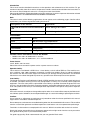
Consumables:
Consumables
Name
Toner
RICOH Toner Type 2210D Black
Photo Conductor Unit
Photo Conductor Unit Type 320
Consumables
Components
Maintenance Kit Type 270
Fusing Unit, Transfer Roller, Paper Feed Rollers, Friction Pads
Software Version Conventions Used in This Manual
•
•
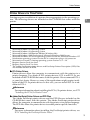
NetWare 3.x refers to NetWare 3.12 and 3.2.
NetWare 4.x refers to NetWare 4.1, 4.11 and IntranetWare.
Power Source
120 V, 60 Hz, 9.0 A or more
Please be sure to connect the power cord to a power source as above.
Operator Safety:
This machine is considered a CDRH class 1 laser device, safe for office/ EDPuse. The machine contains 5-milliwat, 760 - 800 nanometer wavelength, GaAIAs laser diodes. Direct (or indirect reflected)
eye contact with the laser beam might cause serious eye damage. Safety precautions and interlock
mechanisms have been designed to prevent any possible laser beam exposure to the operator.
Laser Safety:
The Center for Devices and Radiological Health (CDRH) prohibits the repair of laser-based optical unit
in the field. The optical housing unit can only be repaired in a factory or at a location with the requisite
equipment. The laser subsystem is replaceable in the field by a qualified Customer Engineer.The laser
chassis is not repairable in the field. Customer engineers are therefore directed to return all chassis and
laser subsystems to the factory or service depot when replacement or the optical subsystem is required.
Important
Parts of this manual are subject to change without prior notice. In no event will the company be liable for direct, indirect, special, incidental, or consequential damages as a result of handling or operating the machine.
Caution:
Use of controls or adjustment or performance of procedures other than those specified in this manual
might result in hazardous radiation exposure.
Do not attempt any maintenance or troubleshooting other than that mentioned in this manual. This machine
contains a laser beam generator and direct exposure to laser beams can cause permanent eye damage.
Two kinds of size notation are employed in this manual. With this machine refer to the inch version.
Ricoh shall not be responsible for any damage or expense that might result from the use of parts other
than genuine Ricoh parts in your Ricoh office product.
For good copy quality, Ricoh recommends that you use genuine Ricoh toner.
Note to users in the United States of America
Notice:
This equipment has been tested and found to comply with the limits for a Class B digital device, pursuant to Part 15 of the FCC Rules. These limits are designed to provide reasonable protection against
harmful interference in a residential installation. This equipment generates, uses and can radiate radio
frequency energy and, if not installed and used in accordance with the instructions, may cause harmful
interference to radio communications.
However, there is no guarantee that interference will not occur in a particular installation. If this equipment does
cause harmful interference to radio or television reception, which can be determined by turning the equipment
off and on, the user is encouraged to try to correct the interference by one more of the following measures:
Reorient or relocate the receiving antenna.
Increase the separation between the equipment and receiver.
Connect the equipment into an outlet on a circuit different from that to which the receiver is
connected.
Consult the dealer or an experienced radio/TV technician for help.
Warning
Changes or modifications not expressly approved by the party responsible for compliance could void
the user's authority to operate the equipment.
Caution (in case of 100BaseTX environment):
1. Properly shielded and grounded cables (STP) and connectors must be used for connections to host
computer (and/or peripheral) in order to meet FCC emission limits.
2. STP with ferrite core must be used for RF interference suppression.
Declaration of Conformity
Product Name: Printer
Model Number: RICOH Aficio AP3200
Responsible party: Ricoh Corporation
Address: 5 Dedrick Place, West Caldwell, NJ 07006
Telephone number: 973-882-2000
This device complies with part 15 of the FCC Rules.
Operation is subject to the following two conditions:
1. This device may not cause harmful interference, and
2. this device must accept any interference received,
including interference that may cause undesired operation.
Note to users in Canada
Note:
This Class B digital apparatus complies with Canadian ICES-003.
Remarque concernant les utilisateurs au Canada
Avertissement:
Cet appareil numérique de la classe B est conforme à la norme NMB-003 du Canada.
In accordance with IEC 60417, this machine uses the following symbols for the main power switch:
a means POWER ON.
b means POWER OFF.
Copyright © 2000 Ricoh Co., Ltd.
Introduction
This manual contains detailed instructions on the operation and maintenance of this machine. To get
maximum versatility from this machine all operators should carefully read and follow the instructions in
this manual. Please keep this manual in a handy place near the machine.
Please read the Safety Information before using this machine. It contains important information related
to USER SAFETY and PREVENTING EQUIPMENT PROBLEMS.
Note
The actual names of the following applications do not appear on the following pages. Confirm which
applications you will be using before reading this manual.
Descriptions in this manual
Application
PRINTER MANAGER FOR ADMINISTRA- Net Vision for Admin
TOR
PRINTER MANAGER FOR CLIENT
Net Vision for Client
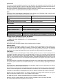
Consumables:
Consumables
Name
Toner
SLP27/P7027 Toner
Photo Conductor Unit
Photo Conductor Unit Type 320
Consumables
Components
Maintenance Kit Type 270
Fusing Unit, Transfer Roller, Paper Feed Rollers, Friction Pads
Software Version Conventions Used in This Manual
• NetWare 3.x refers to NetWare 3.12 and 3.2.
• NetWare 4.x refers to NetWare 4.1, 4.11 and IntranetWare.
Power Source
120 V, 60 Hz, 9.0 A or more
Please be sure to connect the power cord to a power source as above.
Operator Safety:
This machine is considered a CDRH class I laser device, safe for office/ EDPuse. The machine contains 5-milliwat, 760 - 800 nanometer wavelength, GaAIAs laser diodes. Direct (or indirect reflected)
eye contact with the laser beam might cause serious eye damage. Safety precautions and interlock
mechanisms have been designed to prevent any possible laser beam exposure to the operator.
Laser Safety:
The Center for Devices and Radiological Health (CDRH) prohibits the repair of laser-based optical unit
in the field. The optical housing unit can only be repaired in a factory or at a location with the requisite
equipment. The laser subsystem is replaceable in the field by a qualified Customer Engineer.The laser
chassis is not repairable in the field. Customer engineers are therefore directed to return all chassis and
laser subsystems to the factory or service depot when replacement or the optical subsystem is required.
Important
Parts of this manual are subject to change without prior notice. In no event will the company be liable for direct, indirect, special, incidental, or consequential damages as a result of handling or operating the machine.
Caution:
Use of controls or adjustment or performance of procedures other than those specified in this manual
might result in hazardous radiation exposure.
Do not attempt any maintenance or troubleshooting other than that mentioned in this manual. This machine
contains a laser beam generator and direct exposure to laser beams can cause permanent eye damage.
Two kinds of size notation are employed in this manual. With this machine refer to the inch version.
Supplier shall not be responsible for any damage or expense that might result from the use of parts
other than genuine supplier's parts in your supplier's office product.
For good copy quality, supplier recommends that you use genuine supplier's toner.
Read this manual carefully before you use this product and keep it handy for future reference.
For safety, please follow the instructions in this manual.
Note to users in the United States of America
Notice:
This equipment has been tested and found to comply with the limits for a Class B digital device, pursuant to Part 15 of the FCC Rules. These limits are designed to provide reasonable protection against
harmful interference in a residential installation. This equipment generates, uses and can radiate radio
frequency energy and, if not installed and used in accordance with the instructions, may cause harmful
interference to radio communications.
However, there is no guarantee that interference will not occur in a particular installation. If this equipment does
cause harmful interference to radio or television reception, which can be determined by turning the equipment
off and on, the user is encouraged to try to correct the interference by one more of the following measures:
Reorient or relocate the receiving antenna.
Increase the separation between the equipment and receiver.
Connect the equipment into an outlet on a circuit different from that to which the receiver is
connected.
Consult the dealer or an experienced radio/TV technician for help.
Warning
Changes or modifications not expressly approved by the party responsible for compliance could void
the user's authority to operate the equipment.
Caution (in case of 100BaseTX environment):
1. Properly shielded and grounded cables (STP) and connectors must be used for connections to host
computer (and/or peripheral) in order to meet FCC emission limits.
2. STP with ferrite core must be used for RF interference suppression.
Declaration of Conformity
Product Name: Printer
Model Number: SAVIN SLP32/P7032
Responsible party: Ricoh Corporation
Address: 5 Dedrick Place, West Caldwell, NJ 07006
Telephone number: 973-882-2000
This device complies with part 15 of the FCC Rules.
Operation is subject to the following two conditions:
1. This device may not cause harmful interference, and
2. this device must accept any interference received,
including interference that may cause undesired operation.
Note to users in Canada
Note:
This Class B digital apparatus complies with Canadian ICES-003.
Remarque concernant les utilisateurs au Canada
Avertissement:
Cet appareil numérique de la classe B est conforme à la norme NMB-003 du Canada.
In accordance with IEC 60417, this machine uses the following symbols for the main power switch:
a means POWER ON.
b means POWER OFF.
Trademarks
Microsoft®, Windows®, and Windows NT® are registered trademarks of Microsoft Corporation in the United States and/or other countries.
Adobe®, PostScript® and Acrobat® and PageMaker® are registered trademarks
of Adobe System Incorporated.
PCL® is a registered trademark of Hewlett-Packard Company.
AppleTalk, Apple, Macintosh, TrueType, LaserWriter are registered trademarks
of Apple Computer, Incorporated.
IPS-PRINT™ Printer Language Emulation© Copyright 1999-2000, XIONICS
DOCUMENT TECHNOLOGIES, INC., All Rights Reserved.
Ethernet® is a registered trademark of Xerox Corporation.
PowerPC® is a registered trademark of International Business Machines Corporation.
Novell and NetWare are registered trademarks of Novell, Inc.
Other product names used herein are for identification purposes only and might
be trademarks of their respective companies. We disclaim any and all rights involved with those marks.
Notes:
Some illustrations might be slightly different from your machine.
Certain options might not be available in some countries. For details, please contact your local dealer.
Note
The proper names of the Windows operating systems are as follows:
• Microsoft® Windows® 95 operating system
• Microsoft® Windows® 98 operating system
• Microsoft® Windows® Millennium Edition (Windows Me)
• Microsoft® Windows® 2000 Professional
• Microsoft® Windows® 2000 Server
• Microsoft® Windows NT® Server operating system Version 4.0
• Microsoft® Windows NT® Workstation operating system Version 4.0
i
Safety Information
When using your equipment, the following safety precautions should always be
followed.
Safety During Operation
In this manual, the following important symbols are used:
R WARNING:
Indicates a potentially hazardous situation which, if instructions
are not followed, could result in death or serious injury.
R CAUTION:
Indicates a potentially hazardous situation which, if instructions are
not followed, may result in minor or moderate injury or damage to
property.
ii
R WARNING:
• Connect the power cord directly into a wall outlet and never use an extension cord.
• Confirm that the wall outlet is near the machine and freely accessible,
so that in event of an emergency, it can be unplugged easily.
• Disconnect the power plug (by pulling the plug, not the cable) if the
power cable or plug becomes frayed or damaged.
• To avoid hazardous electric shock or laser radiation exposure, do not
remove any covers or screws other than those specified in this manual.
• Turn off the power and disconnect the power plug (by pulling the
plug, not the cable) if any of the following conditions exist:
• You spill something into the equipment.
• You suspect that your equipment needs service or repair.
• Your equipment's cover has been damaged.
• Do not incinerate spilled toner or used toner. Toner dust is flammable
and might ignite when exposed to an open flame.
• Disposal should take place at an authorized dealer or appropriate collection site.
• If you dispose of the used toner containers yourself, dispose of them
according to local regulations.
iii
R CAUTION:
• Protect the equipment from dampness or wet weather, such as rain, snow,
and so on.
• Unplug the power cord from the wall outlet before you move the equipment.
While moving the equipment, you should take care that the power cord will
not be damaged under the equipment.
• When you disconnect the power plug from the wall outlet, always pull the
plug (not the cable).
• Do not allow paper clips, staples, or other small metallic objects to fall inside the equipment.
• Do not eat or swallow toner.
• Keep toner (used or unused) and toner cartridge out of reach of children.
• For environmental reasons, do not dispose of the equipment or expended
supplies at a household waste collection point. Disposal should take place
at an authorized dealer or an appropriate collection site.
• Our products are engineered to meet the highest standards of quality and
functionality. When purchasing expendable supplies, we recommend using
only those specified by an authorized dealer.
• The inside of the machine becomes very hot. Do not touch the parts with a
label indicating a “hot surface”. Touching a “hot surface” could result in a
burn injury. (v: means "hot surface".)
iv
ENERGY STAR Program
As an ENERGY STAR Partner, we have determined
that this machine model meets the ENERGY STAR
Guidelines for energy efficiency.
The ENERGY STAR Guidelines intend to establish an international energy-saving system for
developing and introducing energy-efficient office equipment to deal with environmental issues, such as global warming.
When a product meets the ENERGY STAR Guidelines for energy efficiency, the Partner shall
place the ENERGY STAR logo onto the machine model.
This product was designed to reduce the environmental impact associated with office equipment by means of energy-saving features, such as Low-power mode.
❖ Low-power mode (Energy Saver mode)
This printer automatically lowers its power consumption 30 minutes after the
last operation has been completed. To exit Low-power (Energy Saver) mode,
press any key on the operation panel. For how to configure Energy Saver
mode, see “Using the Operation Panel” in the Printer Reference included as a
PDF file on the CD-ROM.
❖ Specifications
Energy Saver mode
Power Consumption
20 W or less
Default Time
30 minutes
Recovery Time
45 seconds or less
- Recycled Paper
In accordance with the ENERGY STAR Program, we recommend use of recycled
paper which is environment friendly. Please contact your sales representative
for recommended paper.
v
Manuals for This Printer
There are five manuals that separately describe the procedures for the installation of a printer and for the operation and maintenance of the printer and its optional equipment.
To enhance safe and efficient operation of the printer, all users should read and
follow the instructions contained in the following manuals.
❖ Setup Guide
Describes the procedures and provides necessary information about installing and setting up the printer and its options (this manual). This guide is provided as a printed manual, and also as a PDF file on the CD-ROM labeled
“Printer Drivers and Utilities”.
❖ Printer Reference
Describes the procedures and provides necessary information about using
the printer and its options. The manual is included as a PDF file on the CDROM labeled “Printer Drivers and Utilities”.
❖ PostScript 3 Operating Instructions Supplement
Describes the menus and features you can set using the PostScript printer
driver. The manual is included as a PDF file on the CD-ROM labeled “Printer
Drivers and Utilities”.
❖ Network Interface Board Operating Instructions
Describes the procedures and provides necessary information about setting
up and using the printer in a network environment. The manual is included
as a PDF file on the CD-ROM labeled “Printer Drivers and Utilities”.
❖ UNIX Supplement
Provides information about setting up and using the printer in a UNIX environment. This manual is included as a PDF file on the CD-ROM labeled
“Printer Drivers and Utilities”.
vi
How to Read This Manual
Symbols
In this manual, the following symbols are used:
R WARNING:
This symbol indicates a potentially hazardous situation which, if instructions
are not followed, could result in death or serious injury.
R CAUTION:
This symbol indicates a potentially hazardous situation which, if instructions
are not followed, may result in minor or moderate injury or damage to property.
* The statements above are notes for your safety.
Important
If this instruction is not followed, paper might be misfed, originals might be
damaged, or data might be lost. Be sure to read this.
Preparation
This symbol indicates the prior knowledge or preparations required before operating.
Note
This symbol indicates precautions for operation, or actions to take after misoperation.
Limitation
This symbol indicates numerical limits, functions that cannot be used together,
or conditions in which a particular function cannot be used.
Reference
This symbol indicates a reference.
[
]
Keys that appear on the machine's panel display.
Keys and buttons that appear on the computer's display.
{
}
Keys built into the machine's operation panel.
Keys on the computer's keyboard.
vii
TABLE OF CONTENTS
1. Getting Started
Printer Features ......................................................................................... 1
Printer Drivers for This Printer....................................................................... 3
Software and Utilities Included on the CD-ROM..................................... 4
Guide to the Printer ................................................................................... 5
Exterior: Front View....................................................................................... 5
Exterior: Rear View ....................................................................................... 6
Interior ........................................................................................................... 7
Operation Panel ............................................................................................ 8
Keys .............................................................................................................. 9
Guides......................................................................................................... 10
2. Setting Up the Printer
Unpacking the Printer and Checking the Contents of the Box ........... 11
Where to Put the Printer ......................................................................... 14
Installing Options ....................................................................................
Available Options ........................................................................................
Installing PS440/PS420 (Paper Feed Unit).................................................
Installing Interchange Unit Type 280...........................................................
Installing AD380 (Duplex Unit) ....................................................................
Installing Bypass Tray Type 270 .................................................................
Installing Bridge Unit Type 320 ...................................................................
Installing SR510 (500-sheet finisher) ..........................................................
Installing CS370 (Mailbox) ..........................................................................
Installing Memory Unit TypeB .....................................................................
Installing Printer Hard Disk Type 185..........................................................
Installing the Toner Bottle ......................................................................
Loading Paper..........................................................................................
Loading Paper in the Paper Tray ................................................................
Loading Paper in PS420 (Paper Feed Unit)................................................
Loading Paper in Bypass Tray Type 270 ....................................................
Connecting the Power Cord ...................................................................
17
19
21
25
27
31
34
36
38
40
41
43
45
45
48
49
52
Selecting the Panel Display Language.................................................. 53
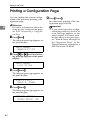
Printing a Configuration Page................................................................ 54
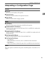
Interpreting a Configuration Page .........................................................
Connecting the Printer............................................................................
Requirements..............................................................................................
Connecting the Printer to the Network ........................................................
Connecting the Printer to the Host Using a Parallel Cable .........................
viii
55
57
57
58
61
3. Configuring the Printer for the Network
Configuring the Printer for the Network with the Operation Panel..... 63
4. Installing the Printer Driver and Software
Installation Method.................................................................................. 69
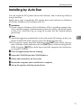
Installing by Auto Run ............................................................................
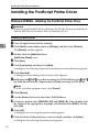
Installing the PCL 6/5e Printer Driver ....................................................
Windows 95/98/Me - Installing the PCL 6/5e Printer Driver ........................
Windows 2000 - Installing the PCL 6/5e Printer Driver ...............................
Windows NT 4.0 - Installing the PCL 6/5e Printer Driver ............................
Installing the PostScript Printer Driver .................................................
Windows 95/98/Me - Installing the PostScript Printer Driver.......................
Windows 2000 - Installing the PostScript Printer Driver..............................
Windows NT 4.0 - Installing the PostScript Printer Driver...........................
Using Adobe PageMaker Version 6.0 or 6.5..........................................
Macintosh.................................................................................................
Macintosh - Installing the PostScript Printer Driver.....................................
Setting Up the PPD File ..............................................................................
Setting Up Options ......................................................................................
71
72
72
72
73
74
74
76
78
81
82
82
83
83
INDEX........................................................................................................ 84
ix
x
1. Getting Started
Printer Features
This printer is designed especially for office workgroups. It can be used in network environments and allows you to manage documents efficiently.
❖ High Productivity
This printer comes with a 32 pages per minute (ppm) engine and offers a variety of paper handling options to handle documents efficiently. The sample
print function*1 is one of the features provided for making multiple print sets
and allows you to confirm that the finish is as expected before starting a long
print run.
*1 Optional Printer Hard Disk Type 185 required.
❖ Versatile Paper Handling Options
This printer offers both versatile input and output paper handling options. Input capacity can be raised to 3,100 sheets with the optional paper bank
(PS420) and the bypass tray (Type 270) to reduce the inconvenience of reloading paper. With the optional mailbox (CS370), you can specify up to five print
delivery destinations, including the standard output tray, to prevent your
prints being mixed up with other peoples. In addition, collation*2 and stapling*2 are available with the optional finisher (SR510 or SR720).
*2 Optional Memory Unit TypeB (32 MB, 64 MB or 128 MB) or Printer Hard
Disk Type 185 required.
❖ Variety of Paper Media Support
Standard tray 2 and optional Bypass Tray Type 270 support a variety of print
media such as thick paper*3, transparencies*3 and certain envelopes*3.
*3 For more information about the supported paper and other media, see “Paper and Other Media” in the Printer Reference included as a PDF file on the
CD-ROM.
❖ Network Interface Board Standard*4
This printer comes with network-ready Ethernet capability supporting multiple protocols as standard. This feature can be used in a variety of network
environments.
*4 For more information about configuring the printer for a network, see the
Operating Instructions for the Network Interface Board included as a PDF file
on the CD-ROM.
❖ Adobe PostScript 3 Standard
In addition to PCL 6 emulation, Adobe PostScript 3 is provided as a standard
feature. This feature can be used in Macintosh environments as well. Adobe
applications can be printed properly and easily.
1
Getting Started
❖ Network Utility
PRINTER MANAGER*5, software consisting of ADMINISTRATOR and CLIENT versions, is provided. With this software, multiple print devices can be
utilized effectively together on a network. This software offers several convenient functions such as parallel printing and recovery printing.
*5 For the name of the PRINTER MANAGER application you have, see the inside of front cover of this manual.
1
❖ Major Specifications
Continuous Printing Speed
32 ppm (A4 long-edge feed or 8 1/2” × 11” long-edge
feed, simplex)
25 ppm (A4 long-edge feed or 8 1/2” × 11” long-edge
feed, duplex)
Resolution
Max. 600 dpi resolution
plus enhanced resolution with edge smoothing
Printer Languages
PCL 5e Emulation, PCL 6 Emulation
Adobe PostScript 3
Paper Input Capacity
500 sheets × 2 trays
Max. 3,100 sheets with options
Paper Output Capacity
500 sheets
Max. 1,750 sheets with options
Memory
32 MB
Max up to 160 MB
HDD
Interface
6.0 GB or more (option)
10BASE-T or 100BASE-TX × 1
IEEE1284 × 1
Options
PS440 (1000-sheet paper feed unit)
PS420 (2000-sheet paper feed unit)
Interchange Unit Type 280
Bypass Tray Type 270
AD380 (duplex unit)
CS370 (mailbox)
Bridge Unit Type 320
SR510 (500-sheet finisher)
SR720 (1000-sheet finisher)
Memory Unit TypeB (32 MB/64 MB/128 MB)
Printer Hard Disk Type 185
2
Printer Features
Printer Drivers for This Printer
Printing requires installation of a printer driver appropriate to the operating system. The following drivers are included on the CD-ROM that comes with this
printer.
1
Printer Language
Operating system
PCL 5e
PCL 6
PostScript 3
*1
√
√
√ *9
Windows 98 *2
√
√
√ *9
√
√
√ *9
√
√
√ *9
√
√ *7
Windows 95
Windows Me *3
Windows 2000
*4
Windows NT 4.0 *5
Macintosh *6
*1
*2
*3
*4
*5
*6
*7
*8
*9
√ *8
*9
√ *9
Microsoft Windows 95 operating system
Microsoft Windows 98 operating system
Microsoft Windows Millennium Edition (Windows Me)
Microsoft Windows 2000 Professional, Microsoft Windows 2000 Server
Microsoft Windows NT Server operating system Version 4.0, Microsoft Windows NT
Workstation operating system Version 4.0 in a computer using a x86 processor.
Macintosh in PowerPC running operating system version 7.6.1 ∼ 9.0.
Requires Service Pack 4 or later.
Requires Service Pack 5 or later.
The Adobe PostScript printer drivers and PostScript Printer Description (PPD) files
are included on the CD-ROM.
❖ PCL Printer Drivers
Printer drivers allow the computer to communicate with the printer via a
printer language. Two kinds of PCL printer drivers, PCL 6 and PCL 5e, are
included on the CD-ROM that comes with this printer. We recommend PCL 6
as your first choice. However, some of the applications might require installation of the PCL 5e printer driver. In this case, you can install PCL 5e in addition to PCL 6.
Reference
For more information about installing the PCL 6/5e printer driver, see P.72
“Installing the PCL 6/5e Printer Driver”.
❖ Adobe PostScript Printer Drivers and PPD Files
The Adobe PostScript printer drivers and the PPD files are included on the
CD-ROM that comes with this printer. The Adobe PostScript printer driver
allows the computer to communicate with the printer via a printer language.
The PPD files allow the printer driver to enable printer specific functions.
Reference
For more information about installing the PostScript printer driver, see
P.74 “Installing the PostScript Printer Driver”.
3
Getting Started
Software and Utilities Included on the CDROM
1
❖ Agfa Font Manager
Helps you to install new fonts, or organize and manage fonts already installed on your system.
❖ PRINTER MANAGER FOR ADMINISTRATOR
A utility for the system administrator to manage printers on the network.
Reference
For the name of the PRINTER MANAGER FOR ADMINISTRATOR application you have, see the inside of front cover of this manual.
For more information, see the Help file.
❖ PRINTER MANAGER FOR CLIENT
A utility for users to manage their own print status on the network.
Reference
For the actual name of the PRINTER MANAGER FOR CLIENT application
you have, see the inside of front cover of this manual.
For more information, see the Help file.
❖ PortNavi
A utility that helps you to use network printers effectively. It is useful in environments where two or more network printers are used.
Reference
For more information about using PortNavi, see the Operating Instructions for the Network Interface Board included as a PDF file on the CDROM.
❖ Multidirect Print
A utility for printing on a "Peer-to-Peer" network.
Reference
For more information about Multidirect Print, see the Operating Instructions for the Network Interface Board included as a PDF file on the CDROM.
❖ Acrobat Reader
A utility that allows you to read PDF (Portable Document Format).
Note
❒ Documentation about using the printer is included on the CD-ROM in a
PDF format.
4
Guide to the Printer
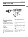
Guide to the Printer
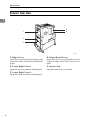
Exterior: Front View
1
6
5
1
2
3
7
8
9
4
10
ZDEH010E
1. Parallel Interface Port
7. Operation Panel
Plug the parallel cable into this port.
Keys for operating the printer and a panel display that shows the printer status.
⇒ P.8 “Operation Panel”
2. Network Interface Port
Plug the network cable into this port.
3. Ventilator
These holes help to keep components inside the printer from overheating. Do not
lean anything against the printer, and do
not block the ventilator.
4. Power Switch
Use this switch to turn the printer power
on and off.
5. Output Tray
Printed output is stacked here with the
print side face down.
6. Upper Right Cover
Open the upper right cover to remove
misfed paper. Remove the upper right
cover to install the optional interchange
unit.
8. Front Cover
Open this cover to replace consumables
or to view instructions for removing misfed paper.
9. Paper Tray
Load up to 500 sheets of plain paper (80
g/m 2, 20 lb). The second tray from the
top can load OHP transparencies or envelopes.
10. PS440 (Optional Paper Feed
Unit)
Load up to 500 sheets of plain paper in its
two trays. PS440 can hold up to 1000
sheets of plain paper (80 g/m 2 , 20 lb).
PS420 can hold up to 2000 sheets of plain
paper (80 g/m2, 20 lb).
5
Getting Started
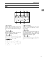
Exterior: Rear View
1
4
5
1
2
3
ZDEH020E
1. Right Cover
4. Printer Board Cover
Open this cover to replace the fusing unit
or transfer roller, or to remove the misfed
paper.
Open this cover to install Memory Unit
TypeB, Printer Hard Disk Type 185 or
both.
2. Lower Right Cover 1
5. Power Cord
Open this cover to remove misfed paper.
Plug this cord into a wall outlet.
3. Lower Right Cover 2
Open this cover to remove misfed paper.
6
Guide to the Printer
Interior
1
1
2
ZAEH030E
3 4 5
6
1. Fusing Unit
4. Toner Holder
When “Replace Maintenance Kit” appears on the panel display, replace this
unit.
Slide this out when replacing the toner.
2. Transfer Unit
When “Replace Maintenance Kit” appears on the panel display, replace this
unit.
3. Toner Lock Lever
5. Photoconductor Unit
When “Replace PCU” appears on the
panel display, replace this unit.
6. Right Cover
Open this cover to access the inside of the
printer.
Lift this lever when replacing the toner.
7
Getting Started
Operation Panel
1
1
2
On Line Job Reset
Form Feed
Power
Error
3
4
Menu
Escape
Enter
Data In
5
ZAES010E
1. Panel Display
4. Error Indicator
Shows the current status of the printer
and error messages. For more information about the messages, see “Error & Status Messages on the Operation Panel” in
the Printer Reference included as a PDF
file on the CD-ROM.
Lights up whenever any printer error occurs. A message describing the cause of
the error also appears on the panel display. For more information about the
messages, see “Error & Status Messages
on the Operation Panel” in the Printer
Reference included as a PDF file on the
CD-ROM.
2. On Line Indicator
Tells you whether the printer is online or
offline.
Stays on while the printer is online (a
state in which the printer can receive data
from the computer).
Stays off when the printer is offline (a
state in which the printer cannot receive
data).
3. Power Indicator
Stays on while the printer power is on.
Stays off when the power is turned off or
while the printer is in the Energy Saver
mode.
8
5. Data In Indicator
Blinks while the printer is receiving data
from a computer or there is data to be
printed.
Guide to the Printer
Keys
1
2
On Line Job Reset
Form Feed
Menu
3
1
4
Escape
Enter
ZAES020E
5
6
7
1. {On Line}} key
5. {Form Feed}} key
Press this key to switch the printer online
or offline. When the printer is online, the
printer can receive data from the computer.
If the printer is offline, press this key to
print out all the data left in the printer's
input buffer.
2. {Job Reset}} key
Press this key to check or change the current printer settings and to switch the
printer offline. To go back to the ready
condition, press this key again.
When the printer is online, press this key
to cancel any ongoing print jobs.
3. {Escape}} key
Press this key to escape from the setup
menu, and to return to the upper level
without making any changes.
4. {U}{T} keys
6. {Menu}} key
7. {Enter #}} key
Press this key to choose menu selected on
the panel display, or to go to a lower level.
Use these keys to scroll through the selected items and to adjust values on the
panel display when making settings. To
change the value more quickly, hold
these keys down.
9
Getting Started
Guides
The guides of the output tray minimize curling of printed output. Use these
guides when you print on A3 short-edge feed, 11" × 17" short-edge feed size paper, or thin paper.
1
❖ To print onto A3 short-edge feed or 11" × 17" short-edge feed size paper
Raise the end fence.
The guide prevents pages from falling off of the output tray.
ZAEH290E
❖ If either side of the page is curled, or if you print onto thin paper
ZAEH330E
Raise the left end of the guide until it clicks into place.
The guide prevents printed pages from curling.
Note
❒ If you use the guides, output capacity is reduced.
10
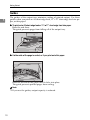
2. Setting Up the Printer
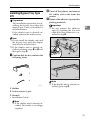
Unpacking the Printer and Checking the
Contents of the Box
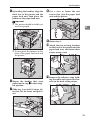
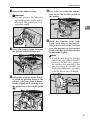
R CAUTION:
• To prevent injuries, this printer
should be lifted by at least two
people.
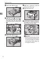
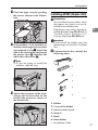
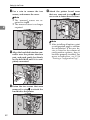
B Remove
the adhesive tape from
the printer as shown in the illustration.
A Check the contents of the box according to the following list. If
any items are missing, please contact your sales or service representative.
• Setup Guide (this manual)
• Additional documentation
• CD-ROM labeled “Printer Driver and Utilities”
• Ferrite core
• Paper size seal
• Tray number seal
Important
❒ The interface cable is not included in the box. It is your responsibility to provide the interface
cable appropriate for the computer you are using. ⇒ P.57
“Connecting the Printer”
❒ The toner bottle is not included
in the box. Consult your sales or
service representative about the
toner bottle.
ZAEH300E
Note
❒ Do not remove the adhesive
tape from the power cord, if you
want to install the optional paper feed unit.
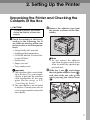
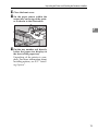
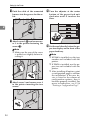
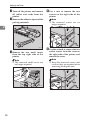
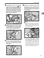
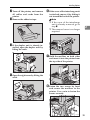
A), and release
C Slide tray 2 out (A
the side guide adhesive lever (B
B),
and then slide the side guide
while pressing the release lever
(C
C).
ZAEH350E
11
Setting Up the Printer
D Remove the adhesive tape.
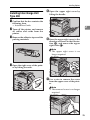
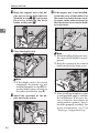
G Slide
tray 1 and tray 2 into the
printer until they stop.
H Open the front cover.
2
ZAEH310E
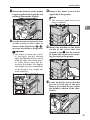
A), and release
E Slide tray 1 out (A
the side guide adhesive lever (B
B),
and then slide the side guide
while pressing the release lever
(C
C).
ZAET010E
I Pull the three red tags on the photoconductor unit to remove the
metal fitting and two tapes.
ZAEH320E
ZAEK010E
F Remove the adhesive tape.
Important
❒ Be sure to remove the red tags
from the photoconductor unit.
An error message will appear
on the panel display if you turn
on the printer power before the
red tags are removed.
ZAEH360E
12
Unpacking the Printer and Checking the Contents of the Box
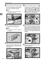
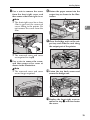
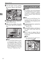
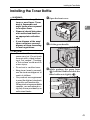
J Close the front cover.
K Set the paper sensor
within the
output tray on the top of the printer as shown in the illustration.
2
ZAEY260E
L Put the tray number seal directly
below the paper size display on
the front of the paper tray.
Unpacking of the printer is complete. For more information about
installing options, see P.17 “Installing Options”.
13
Setting Up the Printer
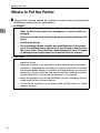
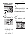
Where to Put the Printer
A The printer's location should be carefully chosen because environmental
conditions greatly affect its performance.
R WARNING:
• Confirm that the wall outlet is near the machine and freely accessible, so that in the event of an emergency, it can be easily unplugged.
2
• Only connect the machine to the power source described on this
sheet.
• Avoid multi-wiring.
• Do not damage, break or make any modifications to the power
cord. Do not place heavy objects on it, pull it hard or bend it more
than necessary. These actions could damage the cord. A frayed
or damaged cord might cause an electrical and fire hazard.
R CAUTION:
• Do not handle the plug with wet hands. Doing this might cause an
electrical shock.
• Keep the machine in an area that is within optimum environmental
conditions. Operating the machine in an environment that is outside
the recommended ranges of humidity and temperature can cause an
electrical or fire hazard. Keep the area around the socket free of dust.
Accumulated dust can become an electrical or fire hazard.
• Place the machine on a strong and level surface. Otherwise, the machine might fall and injure someone.
• If you use the machine in a confined space, confirm there is a continuous air turnover.
14
Where to Put the Printer
❖ Optimum Environmental Conditions
Possible and recommended temperature and humidity ranges are as follows:
RH 10
80
60
40
20
10
80
27
15
70
25
70
15
30
25
30
20
10
32
20
:A
RH 50
80
60
40
20
50
50
80
80
77
70
59
30
77
30
89.6
70
20
ZAEX010E
80
59
70
60
:A
2
30
:B
80.6
20
32
54
89.6
54
20
90
80
:B
ZAEX011E
A: Possible range
B: Recommended range
The machine must be level within 5 mm, 0.2" both front to rear and left to
right.
To avoid possible build-up of ozone, locate this machine in a large well
ventilated room that has an air turnover of more than 30 m3/hr/person.
When you use this machine for a long time in a confined space without
good ventilation, you may notice an odd smell. To keep the workplace
comfortable, we recommend that you keep it well ventilated.
15
Setting Up the Printer
❖ Space Required for Installation
Leave enough space around the printer. This space is necessary to operate
the printer. The recommended (or minimum) space requirements are as
follows:
A
2
B
D
C
ZDEX010E
A: more than 10 cm (4.0")
B: more than 45 cm (17.8")
C: more than 75 cm (29.6")
D: more than 10 cm (4.0")
B Environments to avoid
❒
❒
❒
❒
❒
❒
❒
Important
Locations exposed to direct sunlight or strong light
Dusty areas
Areas with corrosive gases
Areas excessively cold, hot, or humid
Locations near an air conditioner or humidifier
Locations near other electronic equipment
Locations where the printer might be subjected to frequent strong vibration
C Power source
Connect the power cord to a power source with the following specifications:
• 120 V, 60 Hz, 9.0 A or more
16
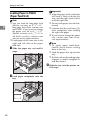
Installing Options
Installing Options
R CAUTION:
• Before installing options, the machine should be turned off and unplugged
for at least thirty minutes. Components inside the machine become very
hot, and can cause a burn injury if touched.
2
• Before moving the machine, unplug the power cord from the outlet. If the
cord is unplugged abruptly, it could become damaged. Damaged plugs or
cords can cause an electrical or fire hazard.
• When lifting the machine, use the grips on both sides. The machine could
break or cause an injury if dropped.
You can increase the functionality of the printer by adding options. See "Options" in the Printer Reference included as a PDF file on the CD-ROM to confirm
what kind of options are available.
If you want to install options, options should be installed in the order described
below.
Important
❒ Rating voltage of the connector for options: max. DC 24 V.
Note
❒ If you want to install SR720 (1000-sheet finisher), Bridge Unit Type 320 and
PS420 or PS440 are required.
❒ If you want to install SR720 (1000-sheet finisher), contact your sales or service
representative.
17
Setting Up the Printer
❖ Option Installation Order
A
Installing the paper feed unit
There are two types of paper feed units: PS440 (1000-sheet
paper feed unit) and PS420 (2000-sheet paper feed unit).
Only one of them can be installed at once. ⇒ P.21 “Installing
PS440/PS420 (Paper Feed Unit)”
T
B
2
Installing Interchange Unit
Type 280
Interchange Unit Type 280 is used for AD380 (duplex unit)
or CS370 (mailbox). If you want to install AD380 (duplex
unit) or CS370 (mailbox), Interchange Unit Type 280 must
be installed first. ⇒ P.25 “Installing Interchange Unit Type
280”
T
C
Installing AD380 (duplex unit)
Install AD380 (duplex unit) on the right side of the printer,
after installing Interchange Unit Type 280. ⇒ P.27 “Installing AD380 (Duplex Unit)”
T
D
Install Bypass Tray Type 270 on the right side of the printer.
Installing Bypass Tray Type 270 ⇒ P.31 “Installing Bypass Tray Type 270”
T
E
Installing Bridge Unit Type 320
Installing Bridge Unit Type 320 is used for SR510 (500-sheet
finisher) or SR720 (1000-sheet finisher). If you want to install
SR510 (500-sheet finisher) or SR720 (1000-sheet finisher),
Bridge Unit Type 320 must be installed first. ⇒ P.34 “Installing Bridge Unit Type 320”
T
F
Installing SR510 (500-sheet finisher)
Install SR510 (500-sheet finisher) on the left side of the printer, after installing Bridge Unit Type 320. ⇒ P.36 “Installing
SR510 (500-sheet finisher)”
T
G
Installing CS370 (mailbox)
Install CS370 (mailbox) on top of Interchange Unit Type 280,
after installing Interchange Unit Type 280. ⇒ P.38 “Installing CS370 (Mailbox)”
T
H
Installing Memory Unit TypeB
There are three types of Memory Unit TypeB, 32 MB, 64 MB
and 128 MB. Only one of them can be installed at once. ⇒
P.40 “Installing Memory Unit TypeB”
T
I
Installing Printer Hard Disk
Type 185
18
⇒ P.41 “Installing Printer Hard Disk Type 185”
Installing Options
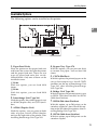
Available Options
The following options can be installed on the printer.
6
5
2
7
8
2
3
4
1
ZDEP011E
1. Paper Feed Units
4. Bypass Tray Type 270
Place the printer on the paper feed unit
and fasten the screws that join the printer
and the paper feed unit. There are two
types of paper feed units that are described below. Only one of them can be
installed at once.
A PS440
With this option, you can load 1000
sheets.
B PS420
With this option, you can load 2000
sheets.
With this option, you can print on thick
or custom size paper. You can load 100
sheets.
2. Interchange Unit Type 280
With this option, the printed paper is sent
to AD380 (duplex unit) or CS370 (mailbox).
3. AD380 (Duplex Unit)
With this option, you can print on both
sides of paper. Install AD380 (duplex
unit) on the right side of the printer, after
installing Interchange Unit Type 280.
5. CS370 (Mailbox)
With this option, the printed paper can be
sent to four output trays. Install CS370
(mailbox) on the top of Interchange Unit
Type 280, after installing Interchange
Unit Type 280.
6. Bridge Unit Type 320
With this option, the printed paper is sent
to SR510 (500-sheet finisher) or SR720
(1000-sheet finisher).
7. SR510 (500-sheet Finisher)
With this option, up to 500 prints can be
sorted or stapled at a time. Install this option on the left side of the printer, after installing Bridge Unit Type 320.
8. SR720 (1000-sheet finisher)
With this option, up to 1000 prints can be
sorted or stapled.
19
Setting Up the Printer
Note
❒ If you want to install SR720 (1000-sheet finisher), Bridge Unit Type 320 and PS420 or
PS440 are required.
❒ If you want to install SR720 (1000-sheet finisher), contact your sales or service representative.
1
2
2
ZDEP020E
1. Printer Hard Disk Type 185
Install Printer Hard Disk Type 185 into
the slots on the printer board.
20
2. Memory Unit TypeB (32 MB, 64
MB or 128 MB)
Install the memory unit into the slots on
the printer board. There are three types of
Memory Unit TypeB, 32 MB, 64 MB and
128 MB. Only one of them can be installed at once.
Installing Options
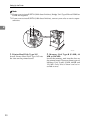
Installing PS440/PS420 (Paper
Feed Unit)
R CAUTION:
• Before installing options, the machine should be turned off and
unplugged for at least thirty minutes. Components inside the
machine become very hot, and
can cause a burn injury if
touched.
• When lifting the machine, use
the grips on both sides. The machine could break or cause an injury if dropped It is dangerous to
handle the plug with wet hands.
Doing this may result in receiving
an electric shock.
• Before moving the machine, unplug the power cord from the outlet. If the cord is unplugged
abruptly, it could become damaged. Damaged plugs or cords
can cause an electrical or fire
hazard.
There are two types of paper feed
units: PS440 (1000-sheet paper feed
unit) and PS420 (2000-sheet paper
feed unit). Only one of them can be installed at once. The installation of
PS440 is described below.
Important
❒ You can load A4 long-edge feed
(Metric version) or 8 1 / 2 " × 11"
long-edge feed (Inch version) size
into PS420. If you want to change
the paper size A4 to 8 1 / 2 " × 11"
(Metric version) or 81/2" × 11" to
A4 (Inch version), contact your
sales or service representative.
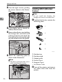
A Confirm that the box contains the
following items.
1
2
2
3
4
5
ZAEP380E
1. Screws (4 pcs)
2. Securing brackets (2 pcs)
3. Cover 1
4. Cover 2
5. Screws (3 pcs)
• Installation Guide
Note
❒ The paper size seal and the tray
number seal are included only
with the printer.
B Turn off the printer, and remove
all cables and cords from the
printer.
21
Setting Up the Printer
C Remove the adhesive tape and the
packing materials.
Important
❒ Do not remove the adhesive
tape holding the cable and the
paper feed unit yet.
2
PS420
A Remove the adhesive tape and
packing material.
PS440
A Remove the adhesive tape and
the adhesive material.
ZDEP360E
D Slide out the four handles on both
sides of the printer.
ZDEP090E
B Slide out the first paper tray
from the top, remove the packing material, and then remove
the adhesive tape and adhesive
material of the friction pad.
ZDEP180E
C Return the first paper tray.
D Slide out the second paper tray
from the top, and then remove
the adhesive tape and adhesive
material of the friction pad.
E Return the second paper tray.
22
ZAEP040E
Installing Options
E By holding the handles, align the
front face of the printer and the
paper feed unit, then place the
printer on the paper feed unit.
H Use
a coin to fasten the two
screws that join the paper feed
unit and the printer.
Important
❒ The printer should be held by at
least two people.
2
ZAEP070E
I Return tray 2.
J Attach the two securing brackets
ZAEP600E
❒ Do not pinch the harness on the
back of the paper feed unit and
the printer.
on the back of the printer and the
paper feed unit, and fasten their
screws using a coin.
ZAEP080E
ZAEP050E
F Return
the handles that were
pulled out in step D to their original position.
K Remove the adhesive tape holding the cable and connect the harness on the back of the printer.
G Slide tray 2 out until it stops. After that, lift the front, and pull it
out.
ZAEP082E
ZAEP060E
23
Setting Up the Printer
L Push the cable of the connected
harness into the groove for the cable.
O Turn
the adjuster at the center
bottom of the paper feed unit
clockwise until it touches the
floor.
2
ZAEP091E
A) and secure covM Attach cover 1 (A
er 1 to the printer fastening the
screw (B
B).
Note
❒ Make sure the core of the screw
is pulled out slightly before inserting it.
1
2
ZAEP671E
N Attach cover 2 and secure cover 2
to the printer inserting the two
screws.
ZDEP060E
24
ZAEP100E
P Put the seal directly below the paper size display on the front of the
paper feed tray.
Note
❒ If PS440 is installed, use the tray
number seal included with the
printer.
❒ If PS420 is installed, use the paper size seal included with the
printer.
❒ After installing all options, print
a configuration page to confirm
the installation. If the new device is listed in the column of
configuration options, then it
has been properly installed. For
more information, see P.54
“Printing a Configuration Page”.
Installing Options
E Open
the upper right cover by
lifting the handle.
Installing Interchange Unit
Type 280
A Confirm that the box contains the
following item.
• Installation Guide
2
B Turn off the printer, and remove
all cables and cords from the
printer.
C Remove the adhesive tape and the
packing materials.
ZAEP630E
F Press the upper right cover in the
direction as shown in the illustration (A
A), and remove the upper
right cover (B
B).
Note
❒ The upper right cover is no
longer required.
ZAEP400E
D Open the right cover of the printer by lifting the catch.
ZAEP150E
G Use
a coin to remove the screw
from the upper cover of the printer.
ZAEP140E
Note
❒ The removed screw is no longer
required.
ZAEP640E
25
Setting Up the Printer
H Put your fingers inside the upper
cover of the printer and remove
the cover by pulling upward.
Note
❒ The upper cover of the printer is
no longer required.
A)
K Open the upper right cover (A
and slide the interchange unit
while keeping the cover perpendicular to the printer (B
B). At this
time, confirm that the projection
(C
C) is placed in the hole securely
as shown in the illustration.
2
90
ZAEP650E
I Remove the interchange unit cover from the interchange unit.
Note
❒ The removed cover is required
in step O.
ZAEP160J
L Fasten
the two screws with fingers, while keeping the upper
right cover of the interchange unit
perpendicular to the printer, and
secure the interchange unit to the
printer. Use a coin to fasten the
screws.
ZAEP500E
J Move the cable to the back of the
printer. Place the interchange unit
onto the printer as shown in the
illustration.
ZAEP161E
M Close the upper right cover of the
interchange unit.
ZAEP162E
ZAEP700E
26
Installing Options
N Close the right cover by pushing
the area as shown in the illustration.
Installing AD380 (Duplex Unit)
Preparation
The installation procedure when
the bypass tray unit is not yet installed is described below.
2
If the bypass tray unit is already installed, perform steps I to J of P.31
“Installing Bypass Tray Type 270”.
You can skip steps E to H below.
ZAEP170E
O If the mailbox is not installed, at-
tach the interchange unit cover that
was removed in step I. Attach the
side of the cover facing the front of
the printer first (A
A) and then the
other side of the cover (B
B).
Important
❒ If you install the duplex unit, the
interchange unit must be installed
first.
A Confirm that the box contains the
following items.
1
Note
❒ If you are going to install the
mailbox, skip this step.
2
3
4
5
ZAEP180E
P Attach the connector of the inter-
6
change unit to the socket on the
back of the printer as shown in
the illustration.
ZAEP382E
1. Holder
2. Cover of the holder
3. Socket screws (3 pcs)
4. Wrench
5. Hook
6. Hook holder
ZDEP070E
• Installation Guide
27
Setting Up the Printer
B Turn off the printer, and remove
all cables and cords from the
printer.
C Remove the adhesive tape and the
packing materials.
E Use
a coin to remove the two
screws on the right side of the
printer.
Note
❒ The removed screws are no
longer required.
2
ZAEP511E
ZAEP412E
D Remove
the two small covers
from the top right side of the
printer.
Note
❒ The removed small covers are
no longer required.
F Use the wrench to remove the two
socket screws from the cover on
the right side of the printer, and
remove the cover.
Note
❒ Keep the removed screws and
cover as they are required when
removing the duplex unit.
ZAEP200E
ZAEP510E
28
Installing Options
G Mount the brackets of the holder
by placing them in the printer and
pushing downwards slightly.
I Remove
the small cover on the
right side of the printer.
Note
❒ The removed small cover is no
longer required.
2
ZAEP210E
H Use the wrench to fasten the four
socket screws in the order as
shown in the illustration (A
A - D),
to secure the holder to the printer.
Important
❒ The order to fasten the screws
is: top right, top left, bottom
right, and bottom left as viewed
from the right side of the printer. If the screws were not fastened in that order, the duplex
unit might not close completely
or the bypass tray might not
work correctly.
ZAEP230E
J Mount the brackets in the holes
in s ide of th e c over th at w as
opened in step I. Use the wrench
to fasten the socket screw securing the hook to the printer.
ZAEP231E
K Lower the duplex unit so that the
groove in each arm of the unit
forms a joint with the pin inside
the holder as shown in the illustration.
ZAEP660E
ZAEP250E
29
Setting Up the Printer
L Hang the support bar in the du-
plex unit on to the hook that was
attached in step J (A
A) and secure
the bar by attaching the hook
holder to the joint (B
B).
O If the bypass tray is not installed,
attach the cover of the holder. Use
the wrench to fasten the two socket screws in the order as shown in
the illustration to secure the holder to the cover.
2
ZAEP260E
ZAEP220E
M Close the duplex unit.
Note
❒ When installing the bypass tray,
the cover of the holder is not required.
❒ Keep the wrench in the wrench
house inside of the front cover.
ZAEP270E
Note
❒ If the duplex unit is not closed
completely, the holder was not
installed properly in step H. Fasten the socket screws securely in
the order described in step H.
N Attach
the connector of the duplex unit to the socket.
ZAEP280E
30
ZAEP540E
❒ After installing all options, print
a configuration page to confirm
the installation. If the new device is listed in the column of
configuration options, then it
has been properly installed. For
more information, see P.54
“Printing a Configuration Page”.
Installing Options
Installing Bypass Tray Type
270
Preparation
The installation procedure for installing the bypass tray when the
duplex unit is not yet installed is
described below.
If the duplex unit is already installed, remove the holder cover.
B Turn off the printer, and remove
all cables and cords from the
printer.
C Remove the adhesive tape and the
packing materials.
Important
❒ Do not remove the adhesive
tape (A) holding the tray and
cable until the connector is attached in step K.
2
Note
❒ If you install the duplex unit and
the bypass tray unit, the duplex
unit must be installed first.
❒ If the duplex unit is already installed, perform steps A to C and
then go to step H.
A Confirm that the box contains the
ZAEP420E
following items.
1
2
ZAEP530E
3
ZAEP430E
Note
❒ If the duplex unit is already installed, go to step H.
1. Holder
2. Socket screws (2 pcs)
3. Wrench
• Installation Guide
Note
❒ If the duplex unit is already installed, the holder is no longer
required.
31
Setting Up the Printer
D Use
a coin to remove the two
screws of the right side of the
printer.
F Mount the brackets of the holder
by placing them in the printer and
pushing downwards slightly.
Note
❒ The two removed screws are no
longer required.
2
ZAEP210E
G Use the wrench to fasten the four
ZAEP201E
E Remove
the two socket screws
holding the cover on the right
side of the printer using the included wrench, and remove the
cover.
Note
❒ Keep the removed screws and
cover as they are required when
removing the duplex unit.
ZAEP510E
32
socket screws in the order shown
in the illustration (A
A - D), to secure the holder to the printer.
ZAEP660E
Important
❒ The order to fasten the screws
is: top right, top left, bottom
right, and bottom left as viewed
from the right side of the printer. If the screws were not fastened in that order, the duplex
unit might not close completely
or the bypass tray might not
work correctly.
Installing Options
H If the duplex unit is not installed,
skip this step and go to step I. If the
duplex unit is installed, the plastic
edges on each side of the unit must
be removed. The edges are held in
place by four small posts. Twist the
edges to break the posts and remove them from the unit.
K Remove the adhesive tape hold-
ing the bypass tray and cable, and
attach the connector to the socket
on the left bottom side of the back
of the printer.
2
ZAEP320E
ZAEP290E
I Slide the bypass tray into the print-
er aligning the grooves of the right
and left sides of the bypass tray
onto the rails inside the holder.
Note
❒ Keep the wrench in the wrench
house inside of the front cover.
Only one wrench can be kept in
the wrench house.
ZAEP541E
ZAEP300E
J Use the wrench to attach the by-
pass tray to the holder. Fasten the
screws in the order shown in the
illustration.
❒ After installing all options, print
a configuration page to confirm
the installation. If the new device is listed in the column of
configuration options, then it
has been properly installed. For
more information, see P.54
“Printing a Configuration Page”.
ZAEP310E
33
Setting Up the Printer
Installing Bridge Unit Type 320
Note
❒ If the mailbox is already installed,
remove the four mailbox trays
from the mailbox.
2
B Turn off the printer, and remove
all cables and cords from the
printer.
C Remove the adhesive tape.
Important
❒ Do not remove the adhesive
tape (A) holding the cable and
the bridge unit until the connector is attached in step N.
ZAEP361E
A Confirm that the box contains the
1
following items.
ZDEP190E
D If the duplex unit is already in-
stalled, open the duplex unit by
lifting the catch.
1
2
ZDEP200E
1. Connecting plate
2. Knob screws (2 pcs)
• Installation Guide
ZAEP330E
E Open the right cover by lifting the
catch.
ZAEP271E
34
Installing Options
F Use
a coin to remove the screw
from the front right cover, and
then remove the front right cover.
H Return the paper sensor into the
output tray as shown in the illustration.
Note
❒ The front right cover has a clear
film to prevent the removed
screw falling in the printer. Do
not remove the screw from the
film.
2
ZDEP370E
I Place the bridge unit on the out-
put tray and slide the unit along
the output part of the printer.
ZDEP210E
❒ The removed screw and cover
are required in step K.
G Use a coin to remove the screw,
and then remove the cover as
shown in the illustration.
ZDEP231E
Note
❒ The removed screw and cover
are no longer required.
ZDEP220E
J Fasten the two knob screws and
secure the bridge unit.
ZDEP380E
K Replace the front right cover removed in step F, and then fasten
the screw.
35
Setting Up the Printer
L Close the right cover by pushing
the area as shown in the illustration.
Installing SR510 (500-sheet
finisher)
Note
❒ If you install the finisher, the
bridge unit must be installed first.
2
A Confirm that the box contains the
following items.
ZDEP240E
1
M If the duplex unit is already installed, close the unit.
N Remove the adhesive tape holding
2
the bridge unit and cable and
packing material, and attach the
connector to the socket on the right
top side of the back of the printer.
3
4
5
ZDEP280E
ZDEP250E
O Attach
the connecting plate as
shown in the illustration.
Note
❒ The plate is fastened with a screw
when installing the finisher.
1. Finisher tray
2. Finisher stand
3. Output guide
4. Screws (2 pcs)
5. Stoppers (2 pcs)
• Installation Guide
B Turn off the printer, and remove
all cables and cords from the
printer.
ZDEP260E
36
Installing Options
C Remove the adhesive tape.
F Use a coin to fasten the screws,
Important
❒ Do not remove the adhesive
tape holding the finisher and cable until the connector is attached in step J.
and secure the finisher stand to
the printer
2
ZDEP301E
G Hold
ZDEP270E
D Insert the output guide between
the printer and the bridge unit.
the finisher with both
hands and keep it horizontal.
Align the holes of the finisher
over the brackets of the finisher
stand, and then push the finisher
downwards slightly.
Note
❒ If you do not keep the finisher
horizontal, you cannot install it
correctly. In this case, remove
the finisher and reinstall it. For
how to remove the finisher, see
the Printer Reference included
as a PDF file on the CD-ROM.
ZDEP290E
E Mount the brackets of the finish-
er stand by placing them in the
printer, and then push it downwards slightly with catching it on
the projection of the output guide
(A
A).
ZDEP310E
ZDEP300E
37
Setting Up the Printer
H Insert
the finisher tray into the
hole of the finisher (A
A).
2
ZDEP320E
I Attach
the two stoppers to the
lower of the finisher output tray
to lock the tray.
ZDEP330E
J Remove the adhesive tape holding the finisher and cable and
packing material, and attach the
connector to the socket on the
bridge unit.
Note
❒ After installing all options, print
a configuration page to confirm
the installation. If the new device is listed in the column of
configuration options, then it
has been properly installed. For
more information, see P.54
“Printing a Configuration Page”.
Installing CS370 (Mailbox)
R CAUTION:
• When lifting the machine, use
the grips on both sides. The machine could break or cause an injury if dropped.
Note
❒ If you install the mailbox, the interchange unit must be installed first.
❒ If you install the mailbox and the
paper feed unit, the paper feed
unit is recommended to be installed first.
A Confirm that the box contains the
following items.
1
2
ZAEP383E
ZDEP340E
1. Mailbox trays (4 pcs)
2. Screws (2 pcs)
• Output tray number seal
• Installation Guide
38
Installing Options
B Turn off the printer, and remove
all cables and cords from the
printer.
C Remove the adhesive tape.
F If the cover of the interchange unit
is attached, remove it by sliding it
out toward the back of the printer.
Note
❒ If the cover of the interchange
unit is already removed, go to
step G.
❒ The removed cover is no longer
required.
2
ZAEP440E
D If the duplex unit is already installed, open the duplex unit by
lifting the catch.
ZAEP710E
G Hold the mailbox on both sides
and insert it into the printer from
the top side of the printer.
ZAEP330E
E Open the right cover by lifting the
catch.
ZAEP340E
H Fasten
the two screws by hand
and secure the mailbox to the
printer. Use a coin to fasten the
screws securely.
ZAEP271E
ZAEP350E
39
Setting Up the Printer
I Close the right cover by pushing
the area as shown in the illustration.
2
ZAEP690E
J If the duplex unit is already installed, close the unit.
K Slide the four mailbox trays into
the lower side of the mailbox
first.
Installing Memory Unit TypeB
Important
❒ The memory unit can be damaged
by small amounts of static electricity. Before touching it, ground
yourself by touching something
metal to remove static electricity
from you.
Note
❒ If you want to install Memory Unit
TypeB and Printer Hard Disk Type
185, Memory Unit TypeB must be
installed first.
A Confirm that the box contains the
following item.
• Memory unit
B Turn off the printer, and remove
all cables and cords from the
printer.
C Use
a coin to remove the six
screws, and remove the printer
board cover.
ZAEP360E
Note
❒ After installing all options, print
a configuration page to confirm
the installation. If the new device is listed in the column of
configuration options, then it
has been properly installed. For
more information, see P.54
“Printing a Configuration Page”.
Note
❒ The removed cover and screws
are required in step E.
ZDEP100E
40
Installing Options
D Tilt the memory unit so that it is
thirty degrees perpendicular to
the slot (A
A), and push it forward
(B
B). It should click into place.
Installing Printer Hard Disk
Type 185
Important
❒ The hard disk can be damaged by
small amounts of static electricity.
Before touching it, ground yourself by touching something metal
to remove static electricity from
you.
2
A Confirm that the box contains the
ZDEP110E
Note
❒ If the hard disk is already installed, remove the hard disk
first.
E Attach
the printer board cover
that was removed in step C, and
use a coin to fasten the six screws.
following items.
• Hard disk
• Installation Guide
B Turn off the printer, and remove
all cables and cords from the
printer.
C Use
a coin to remove the six
screws, and remove the printer
board cover.
Note
❒ The removed cover and screws
are required in step G.
ZDEP101E
Note
❒ If you are now going to install
the hard disk, it is not necessary
to reattach the cover.
❒ After installing all options, print
a configuration page to confirm
the installation. If the new device is listed in the column of
configuration options, then it
has been properly installed. For
more information, see P.54
“Printing a Configuration Page”.
ZDEP100E
41
Setting Up the Printer
D Use
a coin to remove the two
screws, and remove the cover.
Note
❒ The removed screws are required in step F.
❒ The removed cover is no longer
required.
2
G Attach
the printer board cover
that was removed in step C, and
use a coin to fasten the six screws.
ZDEP102E
ZDEP140E
E Align the hard disk interface con-
nector over the printer interface
port, and push gently but firmly
on the hard disk until it is completely connected.
ZDEP150E
F Fasten the two screws that were
removed in step D to attach the
hard disk to the printer.
ZDEP160E
42
Note
❒ After installing all options, print
a configuration page to confirm
the installation. If the new device is listed in the column of
configuration options, then it
has been properly installed. For
more information, see P.54
“Printing a Configuration Page”.
Installing the Toner Bottle
Installing the Toner Bottle
R WARNING:
• Do not incinerate spilled
toner or used toner. Toner
dust is flammable and
might ignite when exposed
to an open flame.
A Open the front cover.
2
• Disposal should take place
at an authorized dealer or
an appropriate collection
site.
ZAET010E
• If you dispose of the used
toner containers yourself,
dispose of them according
to local regulations.
B Lift the green handle.
R CAUTION:
• The inside of the machine becomes very hot. Do not touch
the parts with a label indicating a "hot surface". Touching
a "hot surface" could result in
a burn injury.
• Do not eat or swallow toner.
• Keep toner (used or unused)
and the toner cartridge out of
reach of children.
ZAET020E
C While
pushing the green lever
(A
A), hold the handle and slide the
toner holder out slightly (B
B).
• Our products are engineered
to meet the highest standards
of quality and functionality.
When purchasing expendable
supplies, we recommend using only those provided by an
authorized dealer.
ZAET021E
43
Setting Up the Printer
D Release the green lever and slide
the toner holder out until it stops
gently.
Important
❒ If you continue to push the
green lever to slide the toner
holder, the toner holder might
drop.
2
F Put the toner bottle on the printer
side of the toner holder (A
A), then
push its head downwards to lock
it in place (B
B).
E Move the new toner bottle back
and forth about five or six times
(A
A), and remove the black cap of
the new toner bottle by turning it
counterclockwise (B
B).
ZAET040E
G Slide
the toner holder into the
printer until it clicks into place,
and push the green handle down.
ZAET030E
Important
❒ Do not remove the inside cap.
Note
❒ After removing the black cap
from the bottle, toner can scatter
easily. Do not shake or jar the
bottle.
44
ZAET022E
H Close the front cover.
Loading Paper
Loading Paper
This section describes the type, size,
feed direction, and maximum
amount of paper that can be loaded
into each paper tray in this printer.
B Set
the paper guide lock to the
“unlocked” position.
2
Reference
For more information about the
size and feed direction of paper
that can be set in the tray, see "Paper Type and Sizes" in the Printer
Reference included as a PDF file on
the CD-ROM.
ZAEY011E
Loading Paper in the Paper
Tray
This section describes instructions for
loading paper in the standard paper
tray and optional PS440. If you want
to load paper in PS420, see P.48 “Loading Paper in PS420 (Paper Feed Unit)”.
If you want to load paper in Bypass
Tray Type 270, see P.49 “Loading Paper in Bypass Tray Type 270”.
Important
❒ Confirm that the lever of the
side guide is released before
sliding this guide or it can be
damaged.
C Slide the side paper guide wide
open (B
B) by pressing the release
lever of the side guide (A
A).
A Slide the paper tray out until it
stops.
ZAEY020E
ZAEY010E
45
Setting Up the Printer
D Align all four sides of the paper
stack, and load it into the tray.
E Align the side guide for the loaded paper size (B
B) by opening the
release lever of the side guide (A
A).
2
ZAEY030E
ZAEY031E
Important
❒ Do not stack paper over the limit mark.
F Set
the paper guide lock to the
“locked” position.
❒ When you set thick paper in
tray 2, do not stack paper above
the lower limit mark (A) of tray
2.
ZAEY032E
G Align the rear guide for the loadZAEY052E
ed paper size slightly by pushing
the releasing lever of the rear
guide.
Note
❒ To avoid paper multi-feeds,
shuffle sheets before setting
them in the tray.
❒ Load the paper face up onto the
tray.
ZAEY033E
46
Loading Paper
H Adjust
the paper size dial to
match the size and feed direction
of paper in the paper tray.
ZAEY050E
Important
❒ Confirm that the setting of the
paper size dial matches the paper size and feed direction of
the paper in the tray. If it does
not, misfeeds or unexpected
printing results may occur.
❒ When the actual paper size is
not shown on the dial, set the
dial to "p" and select the paper
size using the operation panel.
For more information about setting up the paper size, see "Paper and Other Media" in the
Printer Reference included as a
PDF file on the CD-ROM.
Note
❒ Thick paper can be set in tray 2
of the printer or Bypass Tray
Type 270. For more information
about loading paper in the bypass tray, see P.49 “Loading Paper in Bypass Tray Type 270”.
When thick paper is placed in
tray 2, move the lever on the paper size dial of tray 2 (A) to
“Non-Standard Paper” mode.
For more information about
loading paper, see "Loading
Thick Paper, Envelope or OHP
Transparencies" in the Printer
Reference included as a PDF file
on the CD-ROM.
2
ZAEH261E
I Slide the tray into the printer until it stops.
47
Setting Up the Printer
Loading Paper in PS420
(Paper Feed Unit)
Note
❒ You can load A4 long-edge feed
(Metric version) or 8 1 / 2 " × 11"
long-edge feed (Inch version) size
into PS420. If you want to change
the paper size A4 to 8 1 / 2 " × 11"
(Metric version) or 81/2" × 11" to
A4 (Inch version), contact your
sales or service representative.
❒ Load paper of the same size in the
right and left sides of the paper
feed unit.
2
A Slide the paper tray out until it
stops.
Important
❒ Align the paper stack so that the
left stack is flush with the left
side, and the right stack is flush
with the right side.
❒ Do not stack paper over the limit mark.
❒ Confirm that the end fence (A)
locks completely after loading
the right side paper.
❒ If you want to change the paper
size, contact your sales or service representative.
Note
❒ To avoid paper multi-feeds,
shuffle sheets before setting
them in the tray.
❒ Load the paper face up onto the
tray.
❒ If either side or the leading edge
of paper is curled, straighten it,
and then load it.
C Slide the tray into the printer until it stops.
ZAEY200E
B Load
paper completely into the
tray.
ZAEY201E
48
Loading Paper
Loading Paper in Bypass Tray
Type 270
Note
❒ Paper sizes supported by the bypass tray are in the approximate
range of 90 - 297 mm (3.54" - 11.69")
in width, and 148 - 432 mm (5.83" 17.00") in length.
❒ To specify a custom size with the
operation panel, see "Specifying a
Custom Paper Size for the Bypass
Tray" in the Printer Reference included as a PDF file on the CDROM.
❒ If you load a custom or unique paper size, set the paper size using
the operation panel.
A Open the bypass tray.
Note
❒ Swing out the extender to support paper sizes longer than A4
short-edge feed (Metric version)
or 8 1/2" × 11" short-edge feed
(Inch version).
C Load the paper and adjust the pa-
2
per guides to the sides of the paper.
ZAEY220E
Important
❒ Confirm the print side of OHP
transparencies. So m e OH P
transparencies can be printed
on only one side.
ZAEY040E
B Lift the paper guide lever.
Note
❒ Do not stack paper over the limit mark. If you do, skew images
or paper misfeeds might occur.
❒ When you set a custom size or
thick paper in the bypass tray,
do not stack paper above the
lower limit mark of the bypass
tray.
❒ To avoid paper multi-feeds,
shuffle sheets before setting
them in the tray.
❒ Load the paper face down onto
the tray.
ZAEY210E
Important
❒ If the paper guides do not match
the paper size, skew images or
paper misfeeds might occur.
49
Setting Up the Printer
D Push down the paper guide lever.
A Press {Menu}
}.
The following message appears
on the panel display.
Main Menu:
Sample Print
B Press {T} or {U} until the following message appears.
2
ZAEY250E
Note
❒ If the paper guide lever is not
pushed down, paper misfeeds
might occur.
E Turn on the printer.
Reference
For more information about
turning on the printer, see P.52
“Connecting the Power Cord”.
F Configure the tray for the loaded
paper size and paper feed direction.
Important
❒ The paper size selected with the
printer driver overrides the one
selected here.
Reference
For more information about
configuring the bypass tray, see
the printer driver Help.
For more information about
l o a d i n g c u s t o m p a p e r , s ee
“Loading Paper and other Media” in the Printer Reference included as a PDF file on the CDROM.
50
Main Menu:
Job Control
C Press {Enter #}
}.
The following message appears
on the panel display.
Job Control:
Paper Input
D Press {Enter #}
}.
The following message appears
on the panel display.
Paper Input:
Tray Priority
E Press {T} or {U} until the following message appears.
Paper Input:
Bypass Size
F Press {Enter #}
}.
The following message appears
on the panel display.
Bypass Size:
Standard Size
Loading Paper
G Press {Enter #}
}.
The currently selected paper
size appears on the panel display.
Standard Size:
*11 x 8 1/2
2
Note
❒ An asterisk (“*”) prefixes the
currently selected item.
H Press {T} or {U} to select the
standard size.
I Press {Enter #}
}.
The following message appears
on the panel display.
Standard Size:
*8 x 13
J After the panel display changes, press {Menu}
}.
The panel display returns to the
ready condition as follows:
Ready
51
Setting Up the Printer
Connecting the Power Cord
R CAUTION:
• Do not handle the plug with wet
hands. Doing this might cause
an electrical shock.
2
A Turn off the printer.
ZAEH220E
B Insert the plug of the power cord
securely into the printer.
C Insert the plug of the power cord
securely into the wall outlet.
Important
❒ Make sure that the printer is
turned off before you insert or
pull the plug of the power cord.
D Turn on the printer.
ZAEH221E
52
Selecting the Panel Display Language
Selecting the Panel Display Language
Messages on the panel display are
shown in English by default. You can
change the language to German,
French, Italian, Dutch, Swedish, Norwegian, Danish, Spanish, Finnish,
Portuguese, Czech, Polish, or Hungarian by following the steps below.
A Press {Menu}}.
The following message appears on
the panel display.
E Press {Enter #}}.
The following message is displayed on the panel display for
two seconds, and then the panel
display automatically returns to
the main menu.
2
Language:
*French
Main Menu:
Sample Print
B Press {T} or {U} until the following message appears.
Main Menu:
Language
C Press {Enter #}}.
The following message appears on
the panel display.
Language:
*English
Note
❒ An asterisk (“*”) prefixes the
currently selected item.
D Press {T} or {U} to display the
language you want to select.
Language:
French
53
Setting Up the Printer
Printing a Configuration Page
You can confirm the current configuration of the printer by printing a configuration page.
Reference
For more information about the
items on the configuration page,
see P.55 “Interpreting a Configuration Page”.
2
A Press {Menu}}.
The following message appears on
the panel display.
Main Menu:
Sample Print
B Press {T} or {U} until the following message appears on the panel
display.
Main Menu:
List Print
C Press {Enter #}}.
The following message appears on
the panel display.
List Print:
Config. Page
D Press {Enter #}}.
The following message appears on
the panel display.
Config. Page:
Press Enter (#)
54
E Press {Enter #}}.
In a short time, printing of the configuration page will start.
Important
❒ If you cannot print the configuration page correctly, check if an
error message appears on the
panel display. For more information about error messages,
see "Error & Status Messages on
the Operation Panel" in the
Printer Reference included as a
PDF file on the CD-ROM.
Interpreting a Configuration Page
Interpreting a Configuration Page
Reference
❖ Printer ID
Shows the serial number of the printer.
2
❖ Firmware Version
Shows the version number of the printer firmware.
❖ Pages Printed
Shows the total number of pages printed.
Memory
❖ Total Memory
Shows the total amount of memory installed on the printer.
❖ Sample/Locked Print Total Memory
Shows the total amount of hard disk space that is available for sample print
and locked print jobs.
❖ Sample/Locked Print Free Memory
Shows the amount of hard disk space that is available for sample print and
locked print jobs.
❖ Font Download Total Memory
Shows the total memory used by the downloaded fonts.
❖ Font Download Free Memory
• Total Memory
Shows the amount of memory that is available for font downloads.
• Free Memory
Shows the amount of hard disk space that is available for font downloads.
Options
Shows the options installed on the printer. Installed option is described as “Installed”.
55
Setting Up the Printer
Job Control
Shows the settings made under the “Job Control” menu.
Reference
For more information about the “Job Control” menu, see “Job Control Menu”
in the Printer Reference included as a PDF file on the CD-ROM.
2
Network Setup
Shows the settings made under the “Network Setup” menu and from the host
computer.
Reference
For more information about the “Network Setup” menu, see “Network Setup” in the Printer Reference included as a PDF file on the CD-ROM.
Maintenance
Shows the settings made under the “Maintenance” menu.
Reference
For more information about the “Maintenance” menu, see “Maintenance
Menu” in the Printer Reference included as a PDF file on the CD-ROM.
Language
Shows the currently selected language in which messages appear on the panel
display.
Reference
For more information about the “Language” menu, see “Language” in the
Printer Reference included as a PDF file on the CD-ROM.
56
Connecting the Printer
Connecting the Printer
Requirements
General
2
Before using this printer, confirm that all the environmental and electrical requirements have been met. Connect the printer to the host computer using the
parallel port, 10BASE-T/100BASE-TX port, or both.
Confirm that all the cables, connectors, and electrical outlets necessary to attach
the printer to the host computer or network are present.
Important
❒ The interface cable is not included in the box. It is your responsibility to provide an interface cable appropriate for the computer you are using.
❒ This printer comes with network-ready Ethernet capability as standard.
Reference
For more information about using a network, see P.58 “Connecting the Printer
to the Network”.
For more information about using the parallel port, see P.61 “Connecting the
Printer to the Host Using a Parallel Cable”.
Network cable
The Network Interface Board supports 10BASE-T or 100BASE-TX connections.
You can use the printer in the following network environments:
• Use the appropriate network management software and printer driver.
• Attach the printer to a networked computer set up as a server.
Client
Windows 95/98/Me, Windows 2000 *1 , Windows NT 4.0 *1 , Macintosh, UNIX
Driver
PCL 6/5e , PostScript 3
File Server
NetWare 3.x, NetWare 4.x, NetWare 5 *2
Protocol
TCP/IP, IPX/SPX, NetBEUI *3 , AppleTalk
*1
*2
*3
Only x86 based computers are supported.
NDPS (Novell Distributed Print Services) mode is not supported.
Under Windows 95/98/Me, Windows 2000 and Windows NT 4.0 only.
Only for Peer-to-Peer printing.
In a mixed network environment, the protocol switches automatically.
57
Setting Up the Printer
Reference
For more information about configuring the Network Interface Board, see the
Operating Instructions for the Network Interface Board included as a PDF file
on the CD-ROM.
For more information about resolving network connection problems, see
"Troubleshooting" in the Printer Reference included as a PDF file on the CDROM.
2
Note
❒ Consult your network administrator before connecting the printer to a network.
❒ In a 100BASE-TX environment, be sure to use properly shielded and grounded cable (STP, Category/Type 5) for the connection to the host computer
(and/or HUB) in order to meet FCC and EMC Directive 89/336/EEC emission guidelines.
Parallel cable
Connect the printer to the host computer parallel port. A parallel cable to connect the printer to the host computer is not included with this printer.
The printer's parallel interface is a standard bidirectional interface. It requires a
standard 36-pin parallel cable compliant with IEEE 1284 and a parallel port
available on the host computer.
Note
❒ Do not use a parallel cable that is longer than 3 meters (10 feet).
Connecting the Printer to the Network
Follow these steps to connect the printer to the network via its built in network
interface.
A Confirm that you have the correct network cable.
B Turn off the printer.
C Loop the network cable twice. The loops should be about 10 cm (4 inch)
from the end of the cable on the end closest to the connector.
58
Connecting the Printer
D Attach the ferrite core to the loops.
2
A
ZAEH250E
A: 10 cm (4 inch)
E Attach the network cable to the 10BASE-T/100BASE-TX port of the printer.
ZAEP370E
Reference
See P.5 “Exterior: Front View” to confirm the position of the 10BASE-T/
100BASE-TX port.
F Connect the other end of the cable to the network.
59
Setting Up the Printer
Buttons and Indicators on the Network Interface Board
1
2
2
3
4
ZAEX010E
1. Indicator (green)
4. Button
Stays on while the printer is in a network
environment.
Hold down this button for more than two
seconds to print the network configuration page. Hold down this button for
more than five seconds to print system
log information.
2. Indicator (green)
Stays on while 100BASE-TX is working.
Stays off while 10BASE-T is working.
3. Indicator (orange)
Stays on while the network interface
board is working.
60
Note
❒ You can print the network configuration page and system log information
using the “Network Status” and “Network Log” menu under the “List
Print” menu on the operation panel.
For more information, see P.54 “Printing a Configuration Page”.
Connecting the Printer
Connecting the Printer to the Host Using a Parallel Cable
Follow these steps to connect the printer to the host computer using a parallel
cable compliant with IEEE 1284.
A Confirm that you have the correct cable.
B Confirm that both the printer and the host computer are turned off. If they
2
are on, turn them off.
C Plug the 36-pin end of the parallel cable into the parallel port of the printer.
ZDEH030E
Reference
See P.5 “Exterior: Front View” to confirm the position of the parallel port.
D Squeeze the wire clips on each side of the connector together until they
snap into place. The clips hold the cable securely in place.
E Plug the other end of the parallel cable into the computer's parallel port.
61
Setting Up the Printer
2
62
3. Configuring the Printer for
the Network
Configuring the Printer for the Network
with the Operation Panel
Reference
This printer contains a Network
Interface Board as a standard. For
more information about configuring for a network, see the Operating Instructions for the Network
Interface Board included as a PDF
file on the CD-ROM.
To use the Network Interface Board,
configure it for the network using the
printer's operation panel.
The following table shows the operation panel settings and their defaults.
These are included in the “Network
Setup” menu.
Setting name
IP Address
Default value
A Press {Menu}}.
The following message appears on
the panel display.
Main Menu:
Sample Print
B Press {T} or {U} until the following message appears.
Main Menu:
Network Setup
C Press {Enter #}}.
The following message appears on
the panel display.
011.022.033.044
Subnet Mask
000.000.000.000
Gateway Address
000.000.000.000
Access Control
000.000.000.000
Network Setup:
IP Address
(Access Control Address)
Access Mask
000.000.000.000
(Access Control
Mask)
Network Boot
None
Frame Type(NW)
Auto Select
(Frame Type NetWare)
ActiveProtocols
All Active
Ethernet
Auto Select
63
Configuring the Printer for the Network
D Referring to the following table,
select the menu item appropriate
to the network.
Active Protocol
Menu item on
the panel display TCP *1 NW *2 AT *3 NB *4
All Active
(Default Setting)
'
'
'
'
None
TCP/IP Only
'
'
NetWare Only
TCP/IP & NetW
3
'
'
'
ATalk Only
TCP/IP & ATalk
'
NetWare & ATalk
TCP & NW &
ATK
'
'
'
'
'
'
'
NetBEUI only
TCP/IP & NB
'
TCP & NB & NW
'
'
NetBEUI & NetW
'
NetBEUI & ATalk
TCP & NB & ATK
NB & NW & ATalk
'
'
'
'
'
*2
*3
*4
Note
❒ An asterisk (“*”) prefixes the
currently selected item.
C Press {T} or {U} until the protocol you want to use appears.
D Press {Enter #}
}.
The actual procedure may differ
depending on the protocol you
use. Follow the appropriate
steps below.
EVFVGVHVJ
'
NetWare
IVJ
'
AppleTalk
J
NetBEUI
J
'
'
'
TCP/IP
NetWare
AppleTalk
NetBEUI
Note
❒ Do not select protocols that are
not used on the network.
❒ When using Pure IP under NetWare 5, select TCP/IP to be active.
A Press {T} or {U} until the following message appears.
Network Setup:
ActiveProtocols
ActiveProtocols:
*All Active
TCP/IP
'
• ' means that this protocol is active.
• A blank cell means this protocol
is not active.
*1
B Press {Enter #}
}.
The following message appears
on the panel display.
E If you use TCP/IP, you should assign an IP address to the printer.
Note
❒ To obtain an IP address for the
printer, contact your network
administrator.
❒ The IP address is shown in dotted decimal format on the panel
display.
A Press {T} or {U} until the following message appears.
Network Setup:
IP Address
64
Configuring the Printer for the Network with the Operation Panel
B Press {Enter #}
}.
Byte 1 of the IP address appears
on the panel display.
IP Address:
Byte 1= 11
C Use {U} or {T} to edit the value.
D Press {Enter #}
}.
Byte 2 of the IP address appears.
IP Address:
Byte 2= 22
E Use {U} or {T} to edit the value.
Repeat steps C and D to specify the remaining bytes.
F Press {Enter #}
} to register the IP
address you specified.
F If you use TCP/IP, you should assign the “Subnet Mask” and
“Gateway Address” using the
same procedure for specifying the
IP address.
G If you use TCP/IP, set the “Access
Control” and “Access Mask” using the same procedure for specifying the IP address, if necessary.
H If you use TCP/IP, you can make
settings for “Network Boot”.
Choose how to obtain the printer's
IP address from a server on the
network. The following methods
are available.
Available methods
Menu item on the
panel display
AR
RA
BO
DH
*1
*2
*3
*4
ARP + PING
'
ARP & RARP
'
ARP & BOOTP
'
ARP&RARP&BOOTP
'
3
'
'
'
'
None
(Default Setting)
RARP + TFTP
'
'
BOOTP
RARP & BOOTP
'
'
DHCP
*1
*2
*3
*4
'
ARP + PING
RARP + TFTP
BOOTP
DHCP
Note
❒ You must have configured the
server in order to use “RARP +
TFTP”, “BOOTP”, or “DHCP”.
A Press {T} or {U} until the following message appears.
Network Setup:
Network Boot
B Press {Enter #}
}.
The current setting appears on
the panel display.
Network Boot:
*None
C Use {T} or {U} until the method you want to use appears.
D Press {Enter #}
}.
65
Configuring the Printer for the Network
I If
you use NetWare, select the
NetWare frame type.
Select one of the items below if
necessary.
• Auto Select (Default)
• Ethernet 802.3
• Ethernet 802.2
• Ethernet II
• Ethernet SNAP
3
Note
❒ In most situations, use the default setting (“Auto Select”).
When you select “Auto Select”,
the frame type first detected by
the printer is adopted. If the network can use more than two
frame types, the printer may fail
to select the correct frame type if
“Auto Select” is selected. In this
case, select the appropriate
frame type.
A Press {T} or {U} until the following message appears.
Network Setup:
Frame Type(NW)
B Press {Enter #}
}.
The current setting appears on
the panel display.
Network Setup:
*Auto Select
C Use {T} or {U} until the frame
type you want to use appears.
D Press {Enter #}
}.
J Exit the setup menu to the available function settings.
A Press {Escape}
}.
B Press {Escape}
}.
66
K
If you want to confirm the printer's configuration, print a configuration page.
A Press {Menu}
}.
The following message appears
on the panel display.
Main Menu:
Sample Print
B Press {T} or {U} until the following message appears.
Main Menu:
List Print
C Press {Enter #}
}.
The following message appears
on the panel display.
List Print:
Config. Page
D Press {Enter #}
}.
The following message appears
on the panel display.
Config. Page:
Press Enter (#)
When printing a configuration
page, you can confirm the printer's configuration.
Configuring the Printer for the Network with the Operation Panel
- Address
❖ Subnet Mask
A number used to mathematically
"mask" or hide an IP Address on
the network by eliminating those
parts of the address that are alike
for all the printers on the network.
Access Control
Mask
IP Addresses that
have access
0.
0.
0.
0
XXX.XXX.XXX.XXX
255.
0.
0.
0
192.XXX.XXX.XXX
255.255.
0.
0
192.168.XXX.XXX
255.255.255.
0
192.168. 15.XXX
255.255.255.255
192.168. 15. 16
❖ Gateway Address
A gateway is a connection or interchange point that connects two
networks. A gateway address is for
the router or host computer used
as a gateway.
3
Note
❒ To obtain the above addresses,
contact your network administrator.
❖ Access Control Address and Access
Control Mask
The Access Control Address and
Access Control Mask are used in
combination with the client's IP
Addresses that have access to the
computer used for printing. If it is
not necessary for you to control the
access rights, select “0.0.0.0”.
Note
❒ When the Access Control Address settings coincide with the
masked result of the IP Address
of the computer, print jobs from
that IP Address can be accepted
by the network interface board.
❒ For example, if you assign
192.168.15.16 as the Access Control Address to the network interface board, the combination
of the Access Control Mask and
IP Address that can have access
are as follows. (xxx: for any numerical value)
67
Configuring the Printer for the Network
3
68
4. Installing the Printer Driver
and Software
This manual assumes that you are familiar with general Windows procedures
and practices. If you are not, see the documentation that comes with Windows
for details.
Installation Method
The following table shows how to install the printer drivers and software.
Auto Run *1
PCL 6 printer driver
Typical *2
Network *3
Custom *4
❍
❍
❍
❍
PCL 5e printer driver
❍
PostScript printer driver
Agfa Font Manager
❍
PRINTER MANAGER FOR
ADMINISTRATOR
❍
PRINTER MANAGER FOR
CLIENT
❍
❍
PortNavi
❍
❍
Multidirect Print
❍
Acrobat Reader
❍
*1
*2
*3
*4
Add Printer
Wizard
Available operating systems are as follows: Windows 95/98/Me, Windows 2000,
Windows NT 4.0
Recommended for most users.
Recommended for network printing users.
Recommended for expert users.
Reference
For more information about the printer drivers, see P.3 “Printer Drivers for
This Printer”. For installing the printer drivers, see P.72 “Installing the PCL 6/
5e Printer Driver” or P.74 “Installing the PostScript Printer Driver”.
For more information about the software and utilities, see P.4 “Software and
Utilities Included on the CD-ROM”.
Important
❒ Before starting this installation, close all documents and applications. In a network environment, confirm that users who are logged on are disconnected.
Be sure to do this when it will create the least interference with other users.
❒ After installing a printer driver, you must restart the computer.
69
Installing the Printer Driver and Software
Note
❒ If the "plug and play" function is started, click [Cancel] in the [New Hardware
Found], [Device Driver Wizard] or [Found New Hardware Wizard] dialog box, and
then insert the CD-ROM. The [New Hardware Found], [Device Driver Wizard] or
[Found New Hardware Wizard] dialog box appears depending on the system version of the Windows 95/98/Me or Windows 2000.
❒ The appropriate language name is used for the CD-ROM folder: ENGLISH
(English), DEUTSCH (German), FRANCAIS (French), ITALIANO (Italian),
ESPANOL (Spanish), NEDRLNDS (Dutch), NORSK (Norwegian), DANSK
(Danish), SVENSKA (Swedish), POLSKI (Polish), PORTUGUS (Portuguese),
SUOMI (Finnish), MAGYAR (Hungarian), CESKY (Czech)
❖ User Codes
User Codes are eight digit numbers that allow you to keep track of printing
done under each code. You can confirm the track with the PRINTER MANAGER FOR ADMINISTRATOR.
4
Reference
For the name of the PRINTER MANAGER FOR ADMINISTRATOR application you have, see the inside of front cover of this manual.
For more information, see the Help file.
70
Installing by Auto Run
Installing by Auto Run
You can install the PCL printer driver and software, and set them up easily by
using Auto Run.
Follow these steps to install the PCL printer driver and software on Windows
95/98/Me, Windows 2000, Windows NT 4.0.
Limitation
❒ If your system is Windows 2000 or Windows NT 4.0, installing a printer driver by Auto Run requires Administrators permission. When you install a printer driver by Auto Run, log on using an account that has Administrators
permission.
Note
❒ Auto Run might not automatically work with certain OS settings. In this case,
launch "INSTTOOL.EXE" located on the CD-ROM root directory.
❒ If you want to cancel Auto Run, hold down the {SHIFT} key (when your system is Windows 2000, hold down the left {SHIFT} key) while inserting the CDROM. Keep the {SHIFT} key held down until the computer has finished accessing the CD-ROM.
4
A Close all applications that are running.
B Insert the CD-ROM into the CD-ROM drive.
C Follow the instructions on the screen.
D Restart the computer after installation is complete.
E Set up the options with the printer driver.
71
Installing the Printer Driver and Software
Installing the PCL 6/5e Printer Driver
Windows 95/98/Me - Installing the PCL 6/5e Printer Driver
Installing the printer driver
Install the driver in accordance with the steps explained. ⇒ P.71 “Installing by
Auto Run”
Setting up options
4
Note
❒ When setting up options, you should access the Printer Properties from Windows. You cannot access the Printer Properties from an application.
A Click [Start] on the taskbar, point to [Settings], and then click [Printers].
The [Printers] window appears.
B Click the icon of the printer you want to use. On the [File] menu, click
[Properties].
C Click the [Accessories] tab.
D Select any options you have installed from the [Options] group.
E Click [OK] .
Windows 2000 - Installing the PCL 6/5e Printer Driver
Installing the printer driver
Install the driver in accordance with the steps explained. ⇒ P.71 “Installing by
Auto Run”
Note
❒ During installation, the [Digital Signature Not Found] dialog box might appears.
In this case, click [Yes] to continue the installation.
Setting up options
Note
❒ When setting up options, you should access the Printer Properties from Windows. You cannot access the Printer Properties from an application.
72
Installing the PCL 6/5e Printer Driver
A Click [Start] on the taskbar, point to [Settings], and then click [Printers].
The [Printers] window appears.
B Click the icon of the printer you want to use. On the [File] menu, click
[Properties].
C Click the [Accessories] tab.
D Select any options you have installed from the [Options] group.
E Click [OK] .
Windows NT 4.0 - Installing the PCL 6/5e Printer Driver
4
Installing the printer driver
Install the driver in accordance with the steps explained. ⇒ P.71 “Installing by
Auto Run”
Setting up options
Note
❒ When setting up options, you should access the Printer Properties from Windows. You cannot access the Printer Properties from an application.
A Click [Start] on the taskbar, point to [Settings], and then click [Printers].
The [Printers] window appears.
B Click the icon of the printer you want to use. On the [File] menu, click
[Properties].
C Click the [Accessories] tab.
D Select any options you have installed from the [Options] group.
E Click [OK] .
73
Installing the Printer Driver and Software
Installing the PostScript Printer Driver
Windows 95/98/Me - Installing the PostScript Printer Driver
Important
❒ Be sure to install the PPD file for Windows 95/98/Me. Do not accidentally install the PPD file for Windows 2000 or Windows NT 4.0.
Installing the printer driver
A Close all applications that are running.
B Click [Start] on the taskbar, point to [Settings], and then click [Printers].
4
The [Printers] window appears.
C Double-click the [Add Printer] icon.
[Add Printer Wizard] starts.
D Click [Next].
E Click [Local printer], and then click [Next].
A dialog box for selecting the printer manufacturer and model name appears.
F Click [Have Disk].
A dialog box for installing a driver from a disk appears.
G Hold down the {SHIFT}} key while inserting the CD-ROM. Keep the {SHIFT}}
key held down until the computer has finished accessing the CD-ROM.
Note
❒ If the Auto Run program starts, click [Cancel].
H Click [Browse].
I Use the [Drives:] list box to select the CD-ROM drive.
J In the box, double-click [DRIVERS], [PS] and [WIN95_98]. Then double-click
the folder of the appropriate language, and double-click [DISK1]. Finally,
click [OK].
K Click [OK].
A dialog box for selecting the printer model appears.
L Click the name of the printer you want to install, and then click [Next].
A dialog box for selecting the printer port appears.
74
Installing the PostScript Printer Driver
M From the [Available ports:] box, select the printer port, and then click [Next].
N Change the name of the printer if you want, and then click [Next].
O In the next dialog box asking if you want to print a test page, select [No] and
then click [Finish].
The installer copies the printer driver files from the CD-ROM to the computer's hard disk.
Note
❒ Print a test page after completing installation and restarting Windows.
P Restart the computer after installation is complete.
Q Set up the options with the printer driver.
4
Setting up options
Note
❒ When setting up options, you should access the Printer Properties from Windows. You cannot set up options when accessing the Printer Properties from
an application.
A Click [Start] on the taskbar, point to [Settings], and then click [Printers].
The [Printers] window appears.
B Click the icon of the printer you want to use. On the [File] menu, click
[Properties].
C Click the [Device Options] tab.
The [Installable options] group appears.
D From the [Installable options] box, select the option you have installed.
The current setting is displayed in the [Change settings for:] list.
E Use the [Change setting for:] list to select the appropriate setting for the selected option.
F Click [Apply] to apply the settings you made.
G After making all settings you want, click [OK].
75
Installing the Printer Driver and Software
Windows 2000 - Installing the PostScript Printer Driver
Limitation
❒ Installing a printer driver requires Manage Printers permission. Members of
the Administrators, and Power Users groups have Manage Printers permission by default. When you install a printer driver, log on using an account
that has Manage Printers permission.
Important
❒ Be sure to install the PPD file for Windows 2000. Do not accidentally install
the PPD file for Windows 95/98/Me or Windows NT 4.0.
Installing the printer driver
4
A Close all applications that are running.
B Click [Start] on the taskbar, point to [Settings], and then click [Printers].
The [Printers] window appears.
C Double-click the [Add Printer] icon.
[Add Printer Wizard] starts.
D Click [Next].
E Click [Local printer], clear the [Automatically detect and install my Plug and Play
printer] check box, and then click [Next].
A dialog box for selecting the printer port appears.
F Click the port you want to use, and then click [Next].
A dialog box for selecting the printer manufacturer and model name appears.
G Click [Have Disk].
A dialog box for installing a driver from a disk appears.
H Hold down the left {SHIFT}} key while inserting the CD-ROM. Keep the left
{SHIFT}
} key held down until the computer has finished accessing the CDROM.
Note
❒ If the Auto Run program starts, click [Cancel].
I Click [Browse].
J In the [Look in:] box, click the CD-ROM drive.
76
Installing the PostScript Printer Driver
K In the box, double-click [DRIVERS], [PS] and [WIN2000]. Then double-click
the folder of the appropriate language for the operating system, and double-click [DISK1]. Finally, click [Open].
L Click [OK].
A dialog box for selecting the printer model appears.
M Click the name of the printer you want to install, and then click [Next].
A dialog box for changing the printer name appears.
N Change the name of the printer if you want, and then click [Next].
O Click [Next].
P In the next dialog box asking if you want to print a test page, select [No] and
4
then click [Next].
A confirmation dialog box appears.
Note
❒ Print a test page after completing installation and restarting Windows.
Q Confirm the settings you have set, and then click [Finish].
The installer copies the printer driver files from the CD-ROM to the computer's hard disk.
Note
❒ If the [Digital Signature Not Found] dialog box appears, click [Yes] to continue
the installation.
R Restart the computer after installation is complete.
S Set up the options with the printer driver.
Setting up options
Limitation
❒ Changing the printer settings requires Manage Printers permission. Members
of the Administrators and Power Users groups have Manage Printers permission by default. When you set up options, log on using an account that has
Manage Printers permission.
Note
❒ When setting up options, you should access the Printer Properties from Windows. You cannot set up options when accessing the Printer Properties from
an application.
A Click [Start] on the taskbar, point to [Settings], and then click [Printers].
The [Printers] window appears.
77
Installing the Printer Driver and Software
B Click the icon of the printer you want to use. On the [File] menu, click [Properties].
C Click the [Device Settings] tab.
D From the [Installable Options] list, select the options you have installed.
E Click [Apply] to apply the settings you made.
F After making all settings you want, click [OK].
Windows NT 4.0 - Installing the PostScript Printer Driver
Limitation
❒ Installing a printer driver requires Full Control access permission. Members
of the Administrators, Server Operators, Print Operators, and Power Users
groups have Full Control permission by default. When you set up options, log
on under Full Control permission.
4
Important
❒ Be sure to install the PPD file for Windows NT 4.0. Do not accidentally install
the PPD file for Windows 95/98/Me or Windows 2000.
Installing the printer driver
A Close all applications that are running.
B Click [Start] on the taskbar, point to [Settings], and then click [Printers].
The [Printers] window appears.
C Double-click the [Add Printer] icon.
[Add Printer Wizard] starts.
D After confirming that the [My Computer] option is selected, click [Next].
A dialog box for selecting the printer port appears.
E Click the check box of the printer port you want to use, and then click [Next].
A dialog box for selecting the printer manufacturer and model name appears.
F Click [Have Disk].
A dialog box for installing a driver from a disk appears.
G Hold down the {SHIFT}} key while inserting the CD-ROM. Keep the {SHIFT}}
key held down until the computer has finished accessing the CD-ROM.
Note
❒ If the Auto Run program starts, click [Cancel].
78
Installing the PostScript Printer Driver
H Change the drive name in the list box to the name of the CD-ROM drive,
and then click [Browse].
I In the box, double-click [DRIVERS], [PS] and [NT4]. Then double-click the
folder of the appropriate language for the operating system, and doubleclick [DISK1]. Finally, click [Open].
J Click [OK].
A printer model selection dialog box appears.
K Click the name of the printer you want to install, and then click [Next].
A dialog box for changing the printer name appears.
L Change the name of the printer if you want, and then click [Next].
M Click [Next].
N In the next dialog box asking if you want to print a test page, select [No] and
4
then click [Finish].
The installer copies the printer driver files from the CD-ROM to the computer's hard disk.
Note
❒ Print a test page after completing installation and restarting Windows.
O Restart the computer after installation is complete.
P Set up the options with the printer driver.
Setting up options
Limitation
❒ Changing the printer settings requires Full Control access permission. Members of the Administrators, Server Operators, Print Operators, and Power Users groups have Full Control permission by default. When you set up options,
log on under Full Control permission.
Note
❒ When setting up options, you should access the Printer Properties from Windows. You cannot set up options when accessing the Printer Properties from
an application.
A Click [Start] on the taskbar, point to [Settings], and then click [Printers].
The [Printers] window appears.
B Click the icon of the printer you want to use. On the [File] menu, click
[Properties].
79
Installing the Printer Driver and Software
C Click the [Device Settings] tab.
D Select any options you have installed from [Installable Options] group.
E Click [OK].
4
80
Using Adobe PageMaker Version 6.0 or 6.5
Using Adobe PageMaker Version 6.0 or 6.5
If you use the printer under Windows 95/98/Me/Windows 2000/Windows NT
4.0 with Adobe PageMaker, you need to copy the PPD file to the PageMaker
folder.
T h e P P D fi le i s t h e f il e w it h e xt e n s io n " . p p d ". I t i s i n t h e f o l d e r
“\PS\WIN95_98\(Language)\DISK1\” on the CD-ROM.
The [WIN95_98] folder, inside the [PS] folder is for the Windows 95/98/Me operating system. Use the folder at this level that is appropriate for the operating system you are using.
The third folder, "(Language)" may be substituted by an appropriate language
name.
4
Reference
For more information about the language name, see P.69 “Installation Method”.
Copy this file to the PageMaker folder.
For the PageMaker 6.0 default installation, the folder is "C:\PM6\RSRC\PPD4",
and for the PageMaker 6.5 default installation, the directory is
"C:\PM65\RSRC\USENGLISH\PPD4". The "USENGLISH" folder may be different, depending on your language selection.
81
Installing the Printer Driver and Software
Macintosh
Macintosh - Installing the PostScript Printer Driver
It is necessary to install a printer driver and a PPD file to print from a Macintosh.
Follow these steps to install a printer driver and a PPD file into a Macintosh using a system 7.6.1 ∼ 9.0 operating system.
A Insert the CD-ROM into the CD-ROM drive.
B Double-click the CD-ROM icon.
C Double-click the [PS DRIVER] folder.
D Double-click the folder of the language you use.
E Open [DISK1] and double-click the installer icon.
F Follow the instructions on the screen.
G Double-click [Extensions].
H Double-click [Printer Descriptions].
I Double-click the CD-ROM icon on the desktop.
J Double-click the [PRINTER DESCRIPTIONS] folder.
K Double-click the folder of the language you use.
L Double-click [DISK1].
M Select all files in [DISK1] and drag them into [Printer Descriptions] in [Exten-
4
sions] in [System Folder].
N Restart the Macintosh.
82
Macintosh
Setting Up the PPD File
Preparation
Confirm that the printer is connected to an AppleTalk network before performing the following procedure.
A On the [Apple] menu, click [Chooser].
B Click the [Adobe PS] icon.
C In the [Select a PostScript Printer:] list, click the name of the printer you want
to use.
D Click [Create].
E Click the printer you want to use, and then click [Select].
4
The PPD file is set up, and the [Adobe PS] icon appears at the left of the printer
name in the list. Next, use the procedure on P.83 “Setting Up Options” to make
the option settings, or close the [Chooser] dialog box.
Setting Up Options
A On the [Apple] menu, select [Chooser].
B Click the [Adobe PS] icon.
C In the [Select the PostScript Printer:] list, click the name of the printer you want
to use, and then click [Setup].
D Click [Configure].
A list of options appears.
E Select the option you want to set up and select the appropriate setting for it.
Note
❒ If the option you want to set up is not displayed, the PPD file might not be
set up correctly. Check the name of the PPD file shown in the dialog box.
F Click [OK].
The list of options closes.
G Click [OK].
The [Chooser] dialog box appears.
H Close the [Chooser] dialog box.
83
INDEX
A
Access Control Address, 63, 67
Access Control Mask, 63, 67
ActiveProtocols, 63
AD380, 27
Agfa Font Manager, 4
Auto Run, 71
B
Bridge Unit Type 320, 34
Bypass Tray Type 270, 31, 49
C
Caution, ii
configuration page, 54, 55
CS370, 38
D
Data In indicator, 8
E
Energy Star, v
Enter # key, 9
Error indicator, 8
Escape key, 9
F
Firmware Version, 55
Font Download Free Memory, 55
Font Download Total Memory, 55
Form Feed key, 9
Frame Type NetWare, 63
front cover, 5
fusing unit, 7
G
Gateway Address, 63, 67
84
I
Interchange Unit Type 280, 25
IP Address, 63
J
Job Control, 56
Job Reset key, 9
L
Language, 56
lower right cover 1, 6
lower right cover 2, 6
M
Macintosh
install, PPD, 82
setting up options, 83
Maintenance, 56
Memory, 55
Memory Unit TypeB, 40
Menu key, 9
Multidirect Print, 4
N
Network Boot, 63
Network Interface Board
Operating Instructions, vi
network interface port, 5
Network Setup, 56
O
On Line indicator, 8
On Line key, 9
operation panel, 5
Options, 17, 55
options, setting up
Macintosh, 83
output tray, 5
P
PageMaker 6.0 or 6.5, 81
Pages Printed, 55
panel display, 8
paper feed unit, 5
paper tray, 5
parallel cable, 58, 61
parallel interface port, 5
PCL 5e, 3
Windows 2000, install, 72
Windows 95/98/Me, install, 72
Windows NT 4.0, install, 73
PCL 6, 3
Windows 2000, install, 72
Windows 95/98/Me, install, 72
Windows NT 4.0, install, 73
photoconductor unit, 7
PortNavi, 4
PostScript, 3
Macintosh, install, 82
Windows 2000, install, 76
Windows 95/98/Me, install, 74
Windows NT 4.0, install, 78
PostScript 3 Operating Instructions
Supplement, vi
power cord, 6
Power indicator, 8
power switch, 5
PPD, 3, 83
printer board cover, 6
printer driver, 72, 73, 78, 3
Printer Hard Disk Type 185, 41
Printer ID, 55
PRINTER MANAGER FOR
ADMINISTRATOR, 4
PRINTER MANAGER FOR CLIENT, 4
Printer Reference, vi
PS420, 21, 48
PS440, 5, 21
S
Safety Information, ii
Sample/Locked Print Free Memory, 55
Sample/Locked Print Total Memory, 55
Setup Guide, vi
SR510, 36
Subnet Mask, 63, 67
T
toner bottle, 43
toner holder, 7
toner lock lever, 7
Total Memory, 55
transfer unit, 7
U
UNIX Supplement, vi
upper right cover, 5
User Code, 70
V
ventilator, 5
W
Warning, ii
Windows 2000
install, PCL 6/5e,
install, PostScript,
Windows 95/98/Me
install, PCL 6/5e,
install, PostScript,
Windows NT 4.0
install, PCL 6/5e,
install, PostScript,
72
76
72
74
73
78
R
Reference, 55
right cover, 6, 7
85
86
UE
USA G062