1
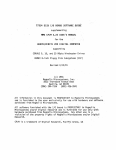
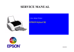
SERVICE MANUAL
Color Inkjet Printer
EPSON Stylus C63/C64/C83/C84
®
SEIJ03004
Notice
o All rights reserved. No part of this manual may be reproduced, stored in a retrieval system, or transmitted in any form or by any means electronic,
mechanical, photocopying, or otherwise, without the prior written permission of SEIKO EPSON CORPORATION.
o The contents of this manual are subject to change without notice.
o All effort have been made to ensure the accuracy of the contents of this manual. However, should any errors be detected, SEIKO EPSON would
greatly appreciate being informed of them.
o The above not withstanding SEIKO EPSON CORPORATION can assume no responsibility for any errors in this manual or the consequences
thereof.
EPSON is a registered trademark of SEIKO EPSON CORPORATION.
General Notice:Other product names used herein are for identification purpose only and may be trademarks or registered trademarks of their respective owners. EPSON disclaims any and all rights in those marks.
Copyright © 2000 SEIKO EPSON CORPORATION.
TPCS Quality Assurance Dept.
PRECAUTIONS
Precautionary notations throughout the text are categorized relative to 1)Personal injury and 2) damage to equipment.
DANGER
Signals a precaution which, if ignored, could result in serious or fatal personal injury. Great caution should be exercised in
performing procedures preceded by DANGER Headings.
WARNING
Signals a precaution which, if ignored, could result in damage to equipment.
The precautionary measures itemized below should always be observed when performing repair/maintenance procedures.
DANGER
1. ALWAYS DISCONNECT THE PRODUCT FROM THE POWER SOURCE AND PERIPHERAL DEVICES PERFORMING ANY
MAINTENANCE OR REPAIR PROCEDURES.
2. NO WORK SHOULD BE PERFORMED ON THE UNIT BY PERSONS UNFAMILIAR WITH BASIC SAFETY MEASURES AS DICTATED
FOR ALL ELECTRONICS TECHNICIANS IN THEIR LINE OF WORK.
3. WHEN PERFORMING TESTING AS DICTATED WITHIN THIS MANUAL, DO NOT CONNECT THE UNIT TO A POWER SOURCE UNTIL
INSTRUCTED TO DO SO. WHEN THE POWER SUPPLY CABLE MUST BE CONNECTED, USE EXTREME CAUTION IN WORKING ON
POWER SUPPLY AND OTHER ELECTRONIC COMPONENTS.
4. WHEN DISASSEMBLING OR ASSEMBLING A PRODUCT, MAKE SURE TO WEAR GLOVES TO AVOID INJURIER FROM METAL PARTS
WITH SHARP EDGES.
WARNING
1. REPAIRS ON EPSON PRODUCT SHOULD BE PERFORMED ONLY BY AN EPSON CERTIFIED REPAIR TECHNICIAN.
2. MAKE CERTAIN THAT THE SOURCE VOLTAGES IS THE SAME AS THE RATED VOLTAGE, LISTED ON THE SERIAL NUMBER/
RATING PLATE. IF THE EPSON PRODUCT HAS A PRIMARY AC RATING DIFFERENT FROM AVAILABLE POWER SOURCE, DO NOT
CONNECT IT TO THE POWER SOURCE.
3. ALWAYS VERIFY THAT THE EPSON PRODUCT HAS BEEN DISCONNECTED FROM THE POWER SOURCE BEFORE REMOVING OR
REPLACING PRINTED CIRCUIT BOARDS AND/OR INDIVIDUAL CHIPS.
4. IN ORDER TO PROTECT SENSITIVE MICROPROCESSORS AND CIRCUITRY, USE STATIC DISCHARGE EQUIPMENT, SUCH AS
ANTI-STATIC WRIST STRAPS, WHEN ACCESSING INTERNAL COMPONENTS.
5. REPLACE MALFUNCTIONING COMPONENTS ONLY WITH THOSE COMPONENTS BY THE MANUFACTURE; INTRODUCTION OF
SECOND-SOURCE ICs OR OTHER NONAPPROVED COMPONENTS MAY DAMAGE THE PRODUCT AND VOID ANY APPLICABLE
EPSON WARRANTY.
About This Manual
This manual describes basic functions, theory of electrical and mechanical operations, maintenance and repair procedures of the printer. The instructions and
procedures included herein are intended for the experienced repair technicians, and attention should be given to the precautions on the preceding page.
Manual Configuration
This manual consists of six chapters and Appendix.
CHAPTER 1.PRODUCT DESCRIPTIONS
Provides a general overview and specifications of the
product.
CHAPTER 2.OPERATING PRINCIPLES
Describes the theory of electrical and mechanical
operations of the product.
CHAPTER 3.TROUBLESHOOTING
Describes the step-by-step procedures for the
troubleshooting.
CHAPTER 4.DISASSEMBLY / ASSEMBLY
Describes the step-by-step procedures for disassembling
and assembling the product.
CHAPTER 5.ADJUSTMENT
Provides Epson-approved methods for adjustment.
CHAPTER 6.MAINTENANCE
Provides preventive maintenance procedures and the
lists of Epson-approved lubricants and adhesives
required for servicing the product.
CHAPTER 7.APPENDIX
Provides the following additional information for
reference:
• Connector pin assignments
• Electric circuit boards components layout
• Electrical circuit boards schematics
• Exploded diagram & Parts List
Symbols Used in this Manual
Various symbols are used throughout this manual either to provide
additional information on a specific topic or to warn of possible danger
present during a procedure or an action. Be aware of all symbols when
they are used, and always read NOTE, CAUTION, or WARNING
messages.
A D J U S T M E N T
R E Q U IR E D
C A U T IO N
Indicates an operating or maintenance procedure, practice
or condition that, if not strictly observed, could result in
injury or loss of life.
Indicates an operating or maintenance procedure, practice,
or condition that, if not strictly observed, could result in
damage to, or destruction of, equipment.
C H E C K
P O IN T
May indicate an operating or maintenance procedure,
practice or condition that is necessary to accomplish a task
efficiently. It may also provide additional information that is
related to a specific subject, or comment on the results
achieved through a previous action.
W A R N IN G
I.ndicates an operating or maintenance procedure, practice
or condition that, if not strictly observed, could result in injury
or loss of life.
Indicates that a particular task must be carried out
according to a certain standard after disassembly and
before re-assembly, otherwise the quality of the
components in question may be adversely affected.
Revision Status
Revision
Issued Date
A
2003/7/31
Description
First Release
CONTENTS
Disassembly and Assembly
Overview......................................................................................................... 8
Precautions ............................................................................................... 8
Tools.......................................................................................................... 9
Work Completion Check.......................................................................... 10
Caution regarding assembling/disassembling
of the printer mechanism, and how to ensure
of quality on re-assembled product ...................................................... 11
Disassembly ................................................................................................. 12
Housing (Right/Left/Frame), Stacker Assy. removal ............................... 13
ASF unit removal..................................................................................... 14
Circuit board removal .............................................................................. 15
Holder shaft unit removal ........................................................................ 17
PS board unit removal............................................................................. 19
CR motor removal ................................................................................... 20
Paper guide upper removal ..................................................................... 21
Front frame removal ................................................................................ 22
CR unit removal....................................................................................... 23
Paper eject roller removal ....................................................................... 27
Paper guide front removal ....................................................................... 28
Printer mechanism/Housing (Lower) removal ......................................... 29
Ink system removal ................................................................................. 32
PF motor removal.................................................................................... 33
Adjustment
Overview....................................................................................................... 35
Required Adjustment............................................................................... 35
Head Angular Adjustment ....................................................................... 37
Bi-D Adjustment ...................................................................................... 37
PF Adjustment......................................................................................... 38
PW Adjustment........................................................................................ 38
First Dot Adjustment................................................................................ 39
Top Margin Adjustment ........................................................................... 39
CR Motor Drive Torque Dispersion Measurement .................................. 39
A4 Normal Print and A4 SF Paper Print .................................................. 39
Maintenance
Overview ......................................................................................................
Cleaning ..................................................................................................
Service Maintenance...............................................................................
Lubrication...............................................................................................
41
41
41
43
Appendix
Electrical Circuits.......................................................................................... 48
Parts List ...................................................................................................... 48
CHAPTER
DISASSEMBLY AND ASSEMBLY
EPSON Stylus C63/64/83/84
Revision A
1.1 Overview
W A R N IN G
This section describes procedures for disassembling the main components of the Stylus
C63/64/83/84. Unless otherwise specified, disassembly units or components can be
reassembled by reversing the disassembly procedure. Things, if not strictly observed,
that could result in injury or loss of life are described under the heading “Warning”.
Precautions for any disassembly or assembly procedures are described under the
heading “CAUTION”. Chips for disassembling procedures are described under the
heading “CHECK POINT”.
If the assembling procedure is different from the reversed procedure of the
disassembling, the procedure is described under the heading “REASSEMBLY”.
Any adjustments required after reassembling the units are described under the heading
“ADJUSTMENT REQUIRED”. When you have to remove any units or parts that are
not described in this chapter, refer to the exploded diagrams in the appendix.
C A U T IO N
n Avant de commencer, assure vous que l’imprimante soit eteinte
et que le cordon d’alimentation soit debranche.
n Veillez a jeter les piles usagees selon le reglement local.
Risque d’explosion si la pile est remplacée incorrectment. Ne
remplacer que par une pile du même type ou d’un type équivalent
recommandé par le fabricant. Eliminer les piles déchargées selon
les lois et les règles de sécurité en vigueur.
Read precautions described in the next section before starting.
C A U T IO N
1.1.1 Precautions
n When transporting the printer after installing the ink cartridge,
See the precautions given under the handling “WARNING” and “CAUTION” in the
following column when disassembling or assembling EPSON Stylus PC63/64/83/84..
n
n Disconnect the power cable before disassembling or assembling
n
n
W A R N IN G
the printer.
n If you need to work on the printer with power applied, strictly
n
n
n
n
follow the instructions in this manual.
Wear protective goggles to protect your eyes from ink. If ink gets
in your eye, flush the eye with fresh water and see a doctor
immediately.
Always wear gloves for disassembly and reassembly to avoid
iujury from sharp metal edges.
To protect sensitive microprocessors and circuitry, use static
discharge equipment, such as anti-static wrist straps, when
accessing internal components.
Never touch the ink or wasted ink with bare hands. If ink comes
into contact with your skin, wash it off with soap and water
immediately. If irritation occurs, contact a physician.
Disassembly and Assembly
Overview
n
n
be sure to pack the printer for transportation without removing
the ink cartridge.
Use only recommended tools for disassembling, assembling or
adjusting the printer.
Observe the specified torque when tightening screws.
Apply lubricants and adhesives as specified. (See Chapter 3 for
details.)
Make the specified adjustments when you disassemble the
printer.
(See Chapter 5 for details.)
Make sure the tip of the waste ink tube is located at correct
position when reassembling the waste ink tube. Otherwise it will
cause ink leakage.
8
EPSON Stylus C63/64/83/84
Revision A
1.1.2 Tools
Use only specified tools to avoid damaging of the printer.
Table 1-1. Tools
Name
Supplier
Parts No.
Phillips Screw Driver (No.2)
EPSON
B743800200
Tweezer
EPSON
B741000100
Hexagon Box Driver
(Opposite side : 5.5 mm)
EPSON
B741700100
Disassembly and Assembly
Overview
9
EPSON Stylus C63/64/83/84
Revision A
1.1.3 Work Completion Check
Table 1-2. Work Completion Check
Classification
If any service is made to the printer, use the checklist shown below to confirm all
works are completed properly and the printer is ready to be returned to the user.
Table 1-2. Work Completion Check
Classification
Lubrication
Item
Self-test
On-line Test
Printhead
Carriage
Mechanism
Main Unit
Check Point
Status
o
Is the operation normal?
o
o
Is the printing successful?
o
Is ink discharged normally from o
all the nozzles?
o
o
Does it move smoothly?
o
o
Is there any abnormal noise
during its operation?
o
o
Is there any dirt or foreign
objects on the CR Guide Shaft? o
o
Is the CR Motor at the correct
temperature?
o
(Not too heated?)
Paper Feeding
Mechanism
•
•
•
•
•
Is paper advanced smoothly?
No paper jamming?
No paper skew?
No multiple feeding?
No abnormal noise?
Is the PF Motor at correct
temperature?
Is the paper path free of any
obstructions?
Adjustment
Specified
Adjustment
Disassembly and Assembly
Are all the adjustment done
correctly?
Item
Specified
Lubrication
Check Point
Are all the lubrication made at
the specified points?
Is the amount of lubrication
correct?
Checked
Not necessary
Function
ROM Version
Version:
Ink Cartridge
Are the ink cartridges installed
correctly?
Protective
Materials
Have all relevant protective
materials been attached to the
printer?
Attachments,
Accessories
Have all the relevant items been
included in the package?
Checked
Not necessary
Checked
Packing
Not necessary
Checked
Not necessary
Others
Checked
Status
o
o
o
o
o
o
o
o
o
o
Checked
Not necessary
Checked
Not necessary
Checked
Not necessary
Checked
Not necessary
Checked
Not necessary
o Checked
o Not necessary
Not necessary
Checked
Not necessary
Checked
Not necessary
o Checked
o Not necessary
o
o
o
o
o
o
Checked
Not necessary
Checked
Not necessary
Checked
Not necessary
Overview
10
EPSON Stylus C63/64/83/84
Revision A
1.2 Caution regarding assembling/disassembling
of the printer mechanism, and how to ensure
of quality on re-assembled product
On current low end models, we basically forbided to remove Housing (Lower) from
Printer mechanism in your repair. This is because there is a possibility of main frame
deformation when a part (such as Ink system) is removed from Printer mechanism
without Housing (Lower).
Therefore, if you want to replace Ink system/PF motor, we recommend to replace with
new Printer mechanism with Housing (Lower).
On these models, you have to remove Housing (Lower) from printer mechanism when
replacing [Porous Pad] with new one.
Therefore, we clarify caution regarding assembling/disassembling of the printer
mechanism without Housing (Lower), and how to ensure of quality on repaired
productsin this section.
[Caution regarding assembling/disassembling of the printer mechanism]
1) Main frame
(a) Control of assembled standard position.
[Reason]
The assembed accuracy of each part composed of Printer mechanism is
based on Housing (Lower).
[Service treatment]
Confirm that there is no gap between main frame and Housing (Lower).
[Reference]
To ensure the assembled accuracy, you have to control the assembled
standard position of main frame against X/Y/Z-axis direction.
[X-axis direction]
- Make sure that main frame is correctly placed on the groove of Housing
(Lower).
- Make sure that there is no gap between main frame and Housing (Lower).
[Y-axis direction]
Make sure that cut-out portion of main frame is correctly placed on the
square protrusion of Housing (Lower).
[Z-axis direction]
- Make sure that there is no gap between main frame and Housing (Lower).
- Make sure that the left side of Printer mechanism is correctly fixed by
two hooks.
Disassembly and Assembly
(b) Control of vertical level of guide rail (Guide rail means the portion latched by
hooks of IC holder & Print head assy..)
[Reason]
There is a possibility that printing failre/operation failure occurs by guide rail
deformation.
[Service treatment]
- Do not remove [Mounting Plate, M/B] from Printer mechanism.
- Hold up the specified position of main frame to avoid the deformation.
(c) How to assemble of ASF unit/Circuit board/Paper guide upper
[Reason]
There is a possibility that main frame deformation is caused extra force in
assembling. As the result, printing failre/operation failure occurs.
[Service treatment]
Hold the opposite side by by hand while you are installing the above parts.
2) Front frame
(a) Control of vertical level
[Reason]
There is a possibility that printing failre occurs by front frame deformation.
[Service treatment]
Handle Front frame in assembling/disassembling carefully.
3) IC holder
(a) Handling of IC holder
[Reason]
If IC holder is damaged in assembling/disassembling of your repair, there is a
possibility that vital problem occus in user’s futher operation.
[Service treatment]
Released two hooks of IC holder from the inside of IC holder by the tweezer.
[How to ensure of quality on re-assembled product]
We judge that the quality of re-assembled product is ensured if there is no problem
about the print result by adjustment program..
Caution regarding assembling/disassembling of the printer mechanism, and how to ensure of quality on re-assembled product
EPSON Stylus C63/64/83/84
Revision A
1.3 Disassembly
The flowchart below shows step-by-step disassembly procedures. When disassembling
each unit, refer to the page number shown in the figure.
Housing (Right/Left/Frame), Stacker assy.
Page 13
*1)
ASF unit removal
Paper guide upper removal
CR motor removal
Page 14
Front frame removal
Page 22
Page 21
Page 20
CR unit removal
Page 23
Circuit board removal
Holder shaft unit removal
Paper eject roller removal
Page 15
Page 17
Page 27
PS board unit removal
Paper guide front removal
Page 19
Page 28
*2)
Printer mechanism/Housing (Lower) removal
Page 29
Ink system removal
PF motor removal
Page 32
Page 33
*1) In "Front frame removal", the procedure only for
removing Front frame is mentioned.
In "CR unit removal, the sequencial procedure of all parts
composed of CR unit is mentioned.
(Added operations before Front frame removal + Front
frame removal + IC holder +Print head assy. / PW sensor
/ CR encoder sensor)
*2) There is some cautions regarding repair of these parts.
As for the details, please refer to 1.2 "Caution regarding
assembling/disassembling of the printer mechanism, and
how to ensure of quality on re-assembled product!.
Figure 1-1. Disassembling flowchart
Disassembly and Assembly
Disassembly
12
EPSON Stylus C63/64/83/84
Revision A
1.3.1 Housing (Right/Left/Frame), Stacker Assy. removal
[Housing (Right/Left/Frame) removal]
1) Releasing five hooks by hand/precision screwdriver (-), and remove Housing
(Right).
2) Release one hook of I/F cover by inserting metal scale vertically from the slit on
bottom of Housing (Left), and remove I/F cover.
3) Releasing five hooks by hand/precision screwdriver (-), and remove Housing
(Left)
4) Release five hooks by hand/precision screwdriver (-), and remove Housing
(Frame).
o External view
2
1
1
3
2
3
4
5
o Removal procedure
4
5
Housing (Right)
Housing (Left)
Insert metal scale from this slit, and
release one hook of I/F cover.
[Stacker assy. removal]
1) Push cut-out portion of Stacker Assy. (left side) by precision screwdriver (-),
and pull Stacker assy. to the front side of the printer.
C A U T IO N
This hook is not only the right
side but also the left side.
o Do not damage hooks by hand/precision screwdriver (-) in
removing Housing (Right/Left) & Stacker assy..
o Do not tilt the printer too much when Housing (Right/Left/
Frame) is removed by hand/precision screwdriver (-). This is
because ink may possible flow if the cap is not covered by
the Print head. (CR is out of the home position)
Damper
Front side
Housing (Frame)
1
o When assembling Housing (Right/Left/Frame) or Stacker
Backside
assy. to printer mechanism,
n Hook five ribs for securing Housing cover (Right/Left)
This marking is the hook that should
be removed/installed.
This marking is more careful hooks
in assembling/disassembling
This marking is the hook portion for
Housing cover (Right/Left) and the
order of assembling.
to Housing (Right/Left) in the order indicated in the
figure.
n Make sure that hooks/protrusions of Housing (Right/
Left/Frame), Stacker assy., SW bottom and Panel board
is correctly fixed to Housing (Frame/Lower).
Stacker assy.
n Make sure that there is not the clearance between
Housing (Right/Left/Frame) and Housing (Lower).
Figure 1-2. Housing (Right/Left/Frame) and Stacker assy. removal
n Make sure that damper for Stacker assy. is correctly
o Part/Unit that should be removed before removing Housing (Right/Left/
installed to the Housing (Lower).
Frame) or Stacker assy..
Non
Disassembly and Assembly
Disassembly
13
EPSON Stylus C63/64/83/84
Revision A
3) Release Extension spring 0.585 for Paper return lever, and remove the lever
with releasing two protrusions.
4) Release Compression spring 1.88 for Returd roller unit, and turn the roller unit
until it is free.
1.3.2 ASF unit removal
o External view
Screw type : C.B.P-TITE, 3x8, F/SN
Order of tightening : Third
Thghtening torque : 6±1 kgf.cm
o When assembling ASF unit,
Screw type : C.B.S-TITE (P4), 3x6, F/SN
Order of tightening : Second
Thghtening torque : 8±1 kgf.cm
n Make sure to latch Extension spring 0.585 for Paper
return lever & Compression spring 1.88 for Returd
roller unit in the order indicated in the figure, and to set
Expression spring 0.585 between ribs of ASF frame.
Screw type : C.B.S SCREW, 3x6, F/SN
Order of tightening : First
Thghtening torque : 8±1 kgf.cm
n Make sure that Paper return lever & Returd roller unit
move smoothly.
ASF unit (Backside)
n Do not touch returd roller and cork on Hopper.
Ribs of ASF frame
2
n Hook two dowels for securing Paper return lever to ASF
1
1
1
frame in the order incicated in the figure.
This marking is
dowel/latched
position and the
order of assembling.
o When assembling ASF unit to main frame,
n Make sure to install Compression spring 2.53 for
2
Compression spring 1.88
Hopper correctly.
Extension spring 0.585
n Make sure that Hopper moves smoothly.
n Make sure to set ASF unit with the flat surface of LD
1
roller up.
2
n Fasten three screws for securing ASF unit in the order/
tightening torque indicated in the figure.
Paper return lever
n Make sure that there is no gap between ASF unit and
Figure 1-3. ASF unit removal
Shield plate (upper) of PS board unit.
o Part/Unit that should be removed before removing ASF unit
A D J U S T M E N T
R E Q U IR E D
Housing (Right/Left/Frame)
the suitable amount of G-26 grease by the specified position.
o When ASF unit is removed or replaced with new one, the
o Removal procedure
1) Remove three screws for securing ASF unit to main frame, and remove the unit
with pulling up slightly to the backside of the printer.
2) Release left protrusion of Hopper by pulling its bottom toward the front side,
and remove Hopper from ASF frame.
Disassembly and Assembly
o When you replace ASF unit with new one, lubricate it with
Disassembly
following adjustment must be performed in the order below.
1) Top margin adjustment
2) 1st dot adjustment
14
EPSON Stylus C63/64/83/84
Revision A
o Removal procedure
1.3.3 Circuit board removal
o External view
Screw type : C.B.S TITE SCREW, 3x14, F/SN
Order of tightening : First
Thghtening torque : 8±1 kgf.cm
Screw type : C.B.S TITE SCREW, 3x10, F/SN
Order of tightening : Third
Thghtening torque : 8±1 kgf.cm
Screw type : C.B.S TITE SCREW, 3x6, F/SN
Order of tightening : 4th
Thghtening torque : 8±1 kgf.cm
Screw type : C.B.S TITE SCREW, 3x14, F/SN
Order of tightening : Second
Thghtening torque : 8±1 kgf.cm
Main board (Backside)
1) Remove Clamp core from [Mounting Plate, M/B], and disconnect the following
seven cables from the corresponding connectors on main board.
- CR motor connector cable
: CN5
- PF motor connector cable
: CN6
- Head FFC
: CN7, CN8
- PE sensor cable
: CN9
- Power supply connect cable
: CN2
- Panel board connector cable
: CN4
2) Remove four screws for securing Circuit board to main frame, and remove
the board.
3) Remove [Shield Plate, M/B] from main board.
o When assembling Circuit board,
n Make sure that the metal fittings for locking the Parallel
interface is on its shield plate.
Far side
HP side
o When assembling Circuit board to main frame,
Shield Plate FFC
n Make sure to connect all cables to the connectors (CN2,
CN4, CN5, CN6, CN7, CN8, CN9) on main board in the
correct direction.
Dowel of cramp core
n Fasten four screws for securing Circuit board in the
order/tightening torque indicated in the figure.
n Make sure that Shield plate FFC on Head FFC is
Cramp core
securely pasted on [Mounting Plate, M/B].
Figure 1-4. Circuit board
n Make sure that two dowels of Clamp core is set in home
position direction.
o Part/Unit that should be removed before removing Circuit board
n Make sure that PE sensor cable & CR motor connector
Housing (Right/Left/Frame) / ASF unit
Disassembly and Assembly
cable are set on Holder shaft unit, and in Clamp core.
Disassembly
15
EPSON Stylus C63/64/83/84
A D J U S T M E N T
R E Q U IR E D
Revision A
o When replacing the Main board with new one, perform the
following service items.
n If the read-out operation succeeds by adjustment
program from defective main board, replace with new
board and write the read out data to new one.
1) Ink consumption counter
2) Waste drain ink pad counter
3) Head ID
4) Bi-d adjustment
5) Top margin adjustment
6) 1st dot position adjustment
7) PW adjustment (Only for SC83/84)
8) USB ID
9) Market ID
10) Head angular adjusstment
11) PF adjustmen
12) CR motor drive torque dispersion measurement
n If the read-out operation is not able to succeed by
adjustment program from defective main board,
perform the following service items after replacing main
board with new one.
1) Replace all ink cartridges with brand-new one for
Ink consumption counter.
2) Replace the Waste drain ink pad with new one for
Waste drain ink pad counter.
3) Input Head ID
4) Adjust Bi-D alignment
5) Adjust Top margin
6) Adjust 1st dot position
7) Adjust PW adjustment
8) Input the serial number for USB ID
9) Input EEPROM initial setting value for Market ID
10) Adjust Head angular
11) Adjust PF (Paper feed amount)
12) Input max. value of CR motor drive torque
dispersion value
Disassembly and Assembly
Disassembly
16
EPSON Stylus C63/64/83/84
Revision A
o Removal procedure
1.3.4 Holder shaft unit removal
o External view
1) Disconnect Panel board connector cable from the connector on main board,
and remove Panel board.
2) Remove Clamp core from [Mounting Plate, M/B] and disconnect Head FFC,
CR motor connector cable and PE sensor cable from the connector on main
board. Then, release Head FFC and CR motor connector cable from Holder
shaft unit.
This marking is the hook/protrusion
for releasing Holder shaft uni.
C A U T IO N
Holder shaft unit (Front side)
Clatch
Spur gear 36.8
1
2
Tension spring 0.143
Idle roller
LD roller shaft unit
Far side
HP side
Shield Plate FFC
Dowel of
cramp core
1
Torsion spring 0.22
Cramp core
1
Plate, M/B]. Therefore, you have to remove Shield plate
FFC with Head FFC.
Holder shaft unit (Backside)
LD roller shaft
2
o Shield plate FFC on Head FFC is pasted on [Mounting
Shield Plate FFC
3) Release Change lever toward the backside of the printer by the tweezer, and
move CR unit to the leftmost side (far side).
4) Remove Holder shaft unit from main frame as belows.
Step1) Push two hooks of LD roller shaft holder, and pull Holder shaft unit
upward slightly from main frame.
Stepe2) Move Pump unit to home position side slightly while holing the whole
of Holder shaft unit, and pull the bottom of the unit toward the
backside of the printer.
5) Remove LD roller shaft along with Clutch mechanism from LD roller shaft
holder.
6) Remove the Spur gear 36.8 from LD roller shaft.
7) Remove Extension spring, 0.143, and remove Clutch from LD roller shaft.
8) Release one hook for securing PE sensor board, and push the sensor board from
the side contacting main frame by the tweezer.
9) Release Torsion spring 0.22 for PE detection levers, and remove the lever from
LD roller shaft holder.
o When assembling PE detection lever & sensor board to LD
This marking is the order of assembling.
roller shaft holder,
n Make sure to set Torsion spring 0.22 for PE detection
Figure 1-5. Holder shaft unit removal
lever to the suitable position.
o Part/Unit that should be removed before removing Holder shaft unit
n Make sure that PE detection lever moves smoothly.
n Make sure that PE sensor board is correctly fixed by the
Housing (Right/Left/Frame) / ASF unit
hook of LD roller shaft holder.
Disassembly and Assembly
Disassembly
17
EPSON Stylus C63/64/83/84
Revision A
n Make sure to place PE sensor cable to the suitable
n Do not damage the tooth of Spur gear 36.8 and
groove on LD roller shaft holder.
Combination gear 27.2, 19.2.
o When assembling Clutch mechanism to LD roller shaft,
o When assembling Panel board to Holder shaft unit,
(This operation is done after installing Holder shaft unit to
main frame.)
n Make sure to set the round hole of Clutch on the dowel
of LD roller shaft.
n Make sure to install Panel board correctly.
n Make sure to set Tension spring 0.143 to the hooks of
n Make sure to place Panel board connector cable on the
Clutch and LD roller shaft.
suitable position of Holder shaft unit.
n Do not set Tension spring 0.143 with twisted condition.
n Make sure that the Clutch rotates properly.
o When assembling LD roller shaft to LD roller shaft holder,
n Do not touch LD roller.
o When assembling Idle roller to LD roller shaft holder,
A D J U S T M E N T
R E Q U IR E D
o When Holder shaft unit is removing or replacing Holder
shaft unit with new one, the following adjustment must be
performed in the order below.
1) Top margin adjustment
2) 1st dot adjustment
(This operation is done after all parts composed of Holder
shaft unit is assembled to LD roller shaft holder.)
o When assembling Holder shaft unit to main frame,
n Make sure that nine hooks of Holder shaft unit are
correctly fixed.
n Make sure to place PE sensor cable, CR motor
connector cable and Head FFC on the suitable position
of Holder shaft unit.
n Make sure to connect PE sensor cable, CR motor
connector cable and Head FFC to the connector (CN5,
CN7, CN8, CN9) on main board.
n Make sure that Shield plate FFC on Head FFC is
securely pasted on [Mounting Plate, M/B].
n Make sure that two dowels of Clamp core is set in home
position direction.
n Make sure that PE sensor cable & CR motor connector
cable are set on Holder shaft unit, and in Clamp core.
n Do not touch LD roller.
Disassembly and Assembly
Disassembly
18
EPSON Stylus C63/64/83/84
Revision A
1.3.5 PS board unit removal
o When assembling the PS board to Shield plate (Lower) ,
o External view
n Make sure to install the PS board correctly.
Screw type : C.B.P-TITE SCREW, 3x8, F/SN
Order of tightening : First
Thghtening torque : 6±1 kgf.cm
n Fasten four screws for securing PS board in the order /
torque indicated in the figure.
o When assembling Shield plate (Upper) to Shield palte
Screw type : C.B.P-TITE SCREW, 3x8, F/SN
Order of tightening : Second
Thghtening torque : 6±1 kgf.cm
(Lower),
n Make sure to place the Power supply connector cable in
the space between both Shield plates.
n Make sure that Shield Plate (Upper) is correctly
inserted.
]
Screw type : C.B.S TITE SCREW, 3x6, F/SN
Order of tightening : First
Thghtening torque : 6±1 kgf.cm
Screw type : C.B.S TITE SCREW, 3x6, F/SN
Order of tightening : 4th
Thghtening torque : 6±1 kgf.cm
Figure 1-7. Assembling of Shield Plate (Upper)
o When assembling PS board unit to Housing (Lower),
Screw type : C.B.S TITE SCREW, 3x6, F/SN
Order of tightening : Third
Thghtening torque : 6±1 kgf.cm
n Make sure to set PS board unit on the protrusion of
Screw type : C.B.S TITE SCREW, 3x6, F/SN
Order of tightening : Second
Thghtening torque : 6±1 kgf.cm
Housing (Lower).
n Make sure to connect Power supply connector cable to
Figure 1-6. PS board unit removal
the connector (CN2) on main board.
n Fasten two screws for securing PS board unit to the
o Part/Unit that should be removed before removing PS board unit
Housing (Lower) in the order /torque indicated in the
figure.
Housing (Right/Left/Frame) / ASF unit / Main board
o Removal procedure
1) Remove three screws for securing PS board unit to main frame, and remove
the unit with pulling toward the backside of the printer.
2) Release one hook of Shield Plate (Upper), and remove four screws for securing
the PS board. Then, remove PS board from Shield plate (Lower).
Disassembly and Assembly
Disassembly
A D J U S T M E N T
R E Q U IR E D
o When PS board unit is removed or replaced with new one,
the following adjustment must be performed in the order
below.
1) Top margin adjustment
2) PF adjustment
3) 1st dot adjustment
4) CR motor drive torque dispersion measurement
19
EPSON Stylus C63/64/83/84
Revision A
1.3.6 CR motor removal
o When assembling the CR motor to main frame,
o External view
n Do not damage CR motor pinion gear with main frame.
Screw type : C.B.S TITE SCREW(P4), 3x6, F/ZN
Order of tightening : non
Thghtening torque : 8±1 kgf.cm
n Make sure to connect the CR motor connector cable to
Screw type : C.P SCREW, 3x4, F/ZN
Order of tightening : First
Thghtening torque : 4±1 kgf.cm
the connector (CN5) on main board.
n Make sure to place CR motor connector cable to Holder
shaft unit properly.
n Fasten two screws for securing CR motor in the order/
tightening torque indicated in the figure.
Compression spring, 20
Holder pulley driven assy.
Stopper
Stopperholder
holderpulley
pulleydriven
driven
Screw type : C.P SCREW, 3x4, F/ZN
Order of tightening : Second
Thghtening torque : 4±1 kgf.cm
n Make sure that there is no gap between CR motor and
frame main.
CR motor
n Make sure to set CR motor upward the serial no. of the
Figure 1-8. CR motor removal
motor.
n Make sure that two dowels of Clamp core is set in home
o Part/Unit that should be removed before removing CR motor
position direction.
n Make sure that PE sensor cable & CR motor connector
Housing (Right/Left/Frame)
cable are set on Holder shaft unit, and in Clamp core.
o Removal procedure
1) Release CR lock lever toward the backside of the printer by the tweezer,
and move CR unit from home position to around the ceter of the printer
mechanism.
2) Loosen one screw for securing Stopper holder pulley driven to main frame &
CR timing belt by pushing Driven pulley holder to the right side, and release
CR timing belt carefully from CR motor pinion gear.
3) Disconnect CR motor connector cable from the connector (CN5) on main
board, and release CR motor connector cable from on Holder shaft unit.
4) Remove two screws for securing CR motor while holding the motor by hand.
C A U T IO N
o When removing CR motor from main frame, do not damage
the pinion gear of the motor.
Disassembly and Assembly
Disassembly
A D J U S T M E N T
R E Q U IR E D
o When CR timing belt is removed or replaced with new one,
tension adjustment of CR timing belt must be performed by
the degital tension gauge.
o When CR motor is removed or replaced with new one, the
following adjustment must be performed in the order below.
1) Top margin adjustment
2) PF adjustment
3) Bi-d adjustment
4) Head angular adjustment
5) 1st dot adjustment
6) PW sensor adjustment (Only for SC83/84)
7) CR motor drive torque dispersion measurement
20
EPSON Stylus C63/64/83/84
Revision A
1.3.7 Paper guide upper removal
C A U T IO N
o External view
o When removing/assembling Paper guide upper, avoid to
damage the coated surface of PF roller by OHP sheet as the
following figure.
Paper guide upper
OHP sheet
Protrusion & Hook
Figure 1-10. Paper guide removal procedure
o When assembling Paper guide upper,
Torsion spring, 60.05
n Make sure to install the tip of Torsion spring 60.05 in
hole of Paper guide upper.
Figure 1-9.
o When assembling Paper guide upper to main frame,
n Make sure that two dowels of Paper guide upper is
o Part/Unit that should be removed before removing Paper guide upper
installed to main frame, and that Torsion spring 60.05 is
set to the protrusion of main frame.
Housing (Right/Left/Frame) / ASF unit / Circuit board / PS board / CR unit with
Front frame / Paper eject roller / Paper guide front / Housing (Lower)
o Removal procedure
A D J U S T M E N T
R E Q U IR E D
1) Push two dowels of Paper guide upper by the tweezer, and pull Paper guide
upper toward the front side of the printer.
Disassembly and Assembly
Disassembly
o When Paper guide upper is removed or replaced with new
one, the following adjustment must be performed in the
order below.
1) Top margin adjustment
2) PF adjustment
3) Bi-d adjustment
4) Head angular adjustment
5) 1st dot adjustment
6) PW sensor adjustment (Only for SC83/84)
21
EPSON Stylus C63/64/83/84
Revision A
1) Return CR unit to home position before removing Front frame.
2) Remove two screws for securing Front frame to main frame.
3) Lift up the left side of Front frame slightly, and slide the frame toward the front
side of the printer.
1.3.8 Front frame removal
o External view
Screw type : C.B.S TITE SCREW, 3x6, F/ZN
Order of tightening : First
Thghtening torque : 8±1 kgf.cm
Screw type : C.B.S TITE SCREW, 3x6, F/ZN
Order of tightening : Second
Thghtening torque : 8±1 kgf.cm
C A U T IO N
o Do not damage [Pulley, Eject, Driven] when sliding the
Front frame to the left side of the printer.
o When assembling Front frame to main frame,
n Make sure that the Star wheel holder & Star wheel eject
Front frame
holder is correctly fixed.
n Make sure that the Star wheel moves smoothly.
Star wheel holder
n Fasten two screws for securing Front frame to main
frame in the order/tightening torque indicated in the
figure.
n Make sure that the CR unit moves smoothly.
Star wheel eject holder
n Make sure that there is no gap between Front frame
frame main.
Figure 1-11. Front frame removal
n Do not hold Front frame while handling printer
mechanism in your repair.
o Part/Unit that should be removed before removing Paper guide front
Housing (Right/Left/Frame)
A D J U S T M E N T
R E Q U IR E D
o Prcedure of removal
C A U T IO N
o The following procedure is only for Front frame removal.
In case that Front frame is removed for CR unit removal,
there is some added operations before Front frame removal.
As for the detailed procedure, refer to 1.2.7 "CR motor
removal".
Disassembly and Assembly
Disassembly
o When you replace Front frame with new one, lubricate it
with the suitable amount of G-58 grease by the specified
position.
o When Front frame is removed or replaced with new one, the
following adjustment must be performed in the order below.
1) PF adjustment
2) Bi-d adjustment
22
EPSON Stylus C63/64/83/84
Revision A
1.3.9 CR unit removal
o External view (Cont.1)
NOTE: "CR unit" described in this section means "IC holder with PW sensor/CR
encoder sensor", "Print head assy.".
Screw type : C.B.S TITE SCREW, 3x6, F/ZN
Order of tightening : First
Thghtening torque : 8±1 kgf.cm
NOTE: The removal procedure for CR unit described in this section is as follows.
Added operations before Front frame removal => Front frame removal
=> IC holder => Print head assy. / PW sensor / CR encoder sensor
Screw type : C.B.S TITE SCREW, 3x6, F/ZN
Order of tightening : Second
Thghtening torque : 8±1 kgf.cm
o External view
Screw type : C.B.S TITE SCREW(P4), 3x6, F/ZN
Order of tightening : non
Thghtening torque : 8±1 kgf.cm
Extension spring, 1.494
CR encoder scale
Cap, Detector, PW
Head FFC
CSIC FFC
Compression spring, 20
Holder pulley driven assy.
Stopper holder pulley driven
PW sensor
Hook
Stopper holder pulley driven
Hook
Dowel
Hook
Figure 1-13. CR unit removal (2)
Pull up IC holder to the front side of the printer with being released
two hooks of IC holder from inside of CR unit by using the tweezer.
Figure 1-12. CR unit removal (1)
Disassembly and Assembly
Disassembly
23
EPSON Stylus C63/64/83/84
Revision A
o Part/Unit that should be removed before removing CR unit removal
11) Pull IC holder slightly to the front side of the printer, and remove CR unit from
main frame.
Housing (Right/Left/Frame)
o Removal procedure
C A U T IO N
1) Release CR lock lever toward the backside of the printer by the tweezer,
and move CR unit from home position to around the center of the printer
mechanism.
2) Remove Clamp core from [Mounting plate, M/B], and disconnect Head FFC
from the connector on main board. Then, release Head FFC from Holder shaft
unit.
C A U T IO N
have to remove [Cover, Detector, PW] and Head FFC.
o There is a possibility of Head FFC damage by excessive
pulling toward the front of the printer without removing
Head FFC.
o Shield plate FFC on Head FFC is pasted on [Mounting
Plate, M/B]. Therefore, you have to remove Shield plate
FFC with Head FFC carefully.
3) Loosen one screw for securing Stopper holder pulley driven to main frame &
CR timing belt by pushing Driven pulley holder to the right side, and release
CR timing belt carefully from CR motor pinion gear.
4) Remove CR encoder scale from main frame.
5) Release one hook for securing Cover cable head to CR unit, and remove Cover
cable head with pushing it down .
6) Release two hooks for securing IC holder to Print head assy.by the tweezer, and
pull IC holder until the holder contacts Front frame.
7) Return CR unit to home position before removing Front frame.
8) Remove two screws for securing Front frame to main frame.
9) Lift up the left side of Front frame slightly, and slide the frame toward the front
side of the printer.
10) Move CR unit to the center of the printer mechanism with holding the whole of
the unit by hand.
C A U T IO N
o You cannot remove IC holder from Print head assy., if you
o Unless you held CR unit by hand, there is a possibility that
Figure 1-14. Head FFC removal
12) Release two hooks for securing [Cap, Detector, PW] to IC holder, and remove
[Cap, Detector, PW].
C A U T IO N
o In case that [Cap, Detector, PW] is removed, PW sensor
board is free. Therefore, be caureful not to damage PW
sensor board.
[Print head removal]
13) Disconnect Head FFC from the connectors on print head board, and remove
Print head assy. from IC holder.
[PW sensor board removal]
13) Disconnect PW sensor FFC from the connector of PW sensor board.
the nozzle surface of Print head is damaged.
[CR encoder sensor board removal]
13) Release two hooks for securing CR encoder sensor board to IC holder, and
disconnect CR encoder senser FFC from the connector of CR encoder sensor
board.
Disassembly and Assembly
Disassembly
24
EPSON Stylus C63/64/83/84
Revision A
o When assembling Print head assy.,
n Make sure that [Cap, Detector, PW] is correctly fixed.
n Make sure that the CR timing belt is set in the
o When assembling CR unit to main frame,
assembling groove correctly.
(CR timing belt is under hook of Print head assy..)
n Make sure that main frame is located between [Roller
n Do not stain the CR timing belt with the grease (G-58).
n Make sure to install [Grounding Plate, Head] in the
guide] and Print head assy..
n Make sure that the right/left hook of Print head assy. is
properly inserted into the hole of IC holder.
suitable position in Print head assy..
n Make sure that four hooks of Cover cable head are
inserted into IC holder.
n Do not touch the lubrication area of main frame.
n Make sure place Head FFC on the suitable position of
Holer roller guide
Holder shaft unit.
Main frame
n Make sure that the CR unit moves smoothly.
n Make sure that Head FFC is fully inserted.
n Make sure that Shield plate FFC is straightly pasted.
Grounding Plate, Head
(not slant.)
Figure 1-15. Setting position of Grounding Plate, Head &
Holer roller guide
n Make sure that PE sensor cable & CR motor connector
cable is set on Holder shaft unit, and in Clamp core.
n Make sure that [Holder Roller Guide] is correctly
installed as the above figure.
o When assembling CR encoder sensor board to IC holder,
n Make sure that CR encoder sensor board is correctly
fixed.
o When assembling CR encoder scale to printer mechanism,
n Make sure that Extension spring 1.494 is not twisted.
n Make sure that CR encoder scale is inserted between
ribs of CR encoder sensor.
n Make sure that CR encoder sensor FFC is correctly
n Make sure that CR encoder is not damaged, or dirt with
connected.
the grease (G-58).
o When assembling Print head assy. to IC holder,
o When assembling CR timing belt to printer mechanism,
n Make sure that Print head assy. is correctly set.
n Make sure that [Stopper, Holder Pulley, Driven] is
n Make sure that Head FFC & PW sensor FFC is
installed into dowels of main frame.
correctly connected with interim condition in
assembling.
n Fasten one screw for securing [Stopper, Holder Pulley,
n Make sure that PW sensor board is correctly located.
Disassembly and Assembly
n Make sure that Clamp core is securely fixed.
Disassembly
Driven] to main frame in the order/tightening torque
indicated in the figure.
25
EPSON Stylus C63/64/83/84
A D J U S T M E N T
R E Q U IR E D
Revision A
o When you replace Holder pulley driven with new one,
lubricate it with the suitable amount of G-65 grease by the
specified position.
A D J U S T M E N T
R E Q U IR E D
o When CR timing belt is removed or replaced with new one,
tension adjustment of CR timing belt must be performed by
the degital tension gauge.
o When you replace Front frame with new one, lubricate it
with the suitable amount of G-58 grease by the specified
position.
o When you replace IC holder or Print head assy. with new
one, lubricate it with the suitable amount of G-58 grease by
the specified position.
o When you replace Pulley driven shaft with new one,
lubricate it with the suitable amount of G-58 grease by the
specific position.
o When you replace Pulley driven holder with new one,
lubricate it with the suitable amount of G-58 grease by the
specific position.
o When IC holder/PW sensor/CR encoder sensor is removed
or replaced with new one, the following adjustment must be
performed in the order below.
1) Top margin adjustment
2) PF adjustment
3) Bi-d adjustment
4) Head angular adjustment
5) 1st dot adjustment
6) PW sensor adjustment (Only for SC83/84)
7) CR motor drive torque dispersion measurement
o When Print head assy. is removed or replaced with new one,
the following adjustment must be performed in the order
below.
1) Head ID input
2) Top margin adjustment
3) PF adjustment
4) Bi-d adjustment
5) Head angular adjustment
6) 1st dot adjustment
7) PW sensor adjustment (Only for SC83/84)
8) CR motor drive torque dispersion measurement
Disassembly and Assembly
Disassembly
26
EPSON Stylus C63/64/83/84
Revision A
1.3.10 Paper eject roller removal
o When assembling Paper eject roller to main frame,
o External view
Pulley, PF, Driven
n Do not touch the rubber portion.
n Make sure that [Bushing, 6] is correctly fixed.
Pulley, Eject, Driven
Bushing, 6
n Do not damage the tooth of [Pulley, Eject, Driven] while
PF timing belt is set.
SPACER, 4.1x0.5
n Make sure that Spacers for [Pulley, Eject, Driven] &
PF timing belt
[Bushing, 6] is correctly inserted to the slit of PF eject
roller.
SPACER, 4.1x0.5
(This spacer is adopted only for SC83/84.
On SC63/64, Paper eject roller shaft is
pressed to [Pulley, Eject, Driven].)
n Make sure that the Paper eject roller moves smoothly.
n On SC63/64, when Paper eject roller shaft from [Pulley,
Eject, Driven], two hooks on Paper eject roller shaft are
damaged. Therefore, do not use the shaft again because
the paper feeding accuracy is lower.
Paper eject roller
Figure 1-16. Paper eject roller removal
n On SC83/84, you can use removed Paper eject roller
o Part/Unit that should be removed before removing Paper eject roller
shaft again by being careful of conbination direction
between Paper guide shaft and Pulley. Therefore, mark
on the shaft and Pulley before removing the shaft.
(This marking is done in manufactory. But, please
ignore the marking in your service.
Housing (Right/Left/Frame) / CR unit with Front frame
o Removal procedurel
1) Loosen PF timing belt with pulling the timing belt to the left side from
[Pulley, PF, Driven]
2) Remove one spacer for securing [Pulley, Eject, Driven] to Paper eject roller,
and remove [Pulley, Eject, Driven] with pulling it to the left side of the
printer.
3) Remove one spacer for securing [Bushing, 6] to Paper eject roller, and turn
[Bushing, 6] until it is free. (The end of [Bushing, 6] rotates to the front side
of the printer.)
4) Slide Paper eject roller to home position side slightly, and pull up the left end of
the roller.
5) Remove Paper eject roller with sliding to the left side of the printer.
C A U T IO N
o Do not damage rubber portion of Paper eject roller when
sliding the roller to the left side of the printer.
Disassembly and Assembly
Disassembly
A D J U S T M E N T
R E Q U IR E D
o When you replace Paper eject roller with new one, lubricate
it with the suitable amount of G-58 grease by the specified
position.
o When PF timing belt is removed or replaced with new one,
tension adjustment of PF timing belt must be performed by
the degital tension gauge.
o When Paper eject roller is removed or replaced with new
one, the following adjustment must be performed in the
order below.
1) Top margin adjustment
2) PF adjustment
3) Bi-d adjustment
4) Head angular adjustment
5) 1st dot adjustment
6) PW sensor adjustment (Only for SC83/84)
27
EPSON Stylus C63/64/83/84
Revision A
o Removal procedure
1.3.11 Paper guide front removal
o External view
1) Remove one screw for securing Paper guide front to main frame, and remove
Paper guide front with pulling the left side of Paper guide front slightly.
Porous Pad, Paper guide front
Screw type : CBS TITE SCREW, 3x6, F/Zn
Order of tightening : First
Thghtening torque : 8±1 kgf.cm
C A U T IO N
o Do not touch the rib of Paper guide front and [Porous Pad,
Paper guide, Front].
o Do not touch eight feet of [Porous Pad, Paper guide, Front;
Sub].
Ribs of Paper guide front
o When assembling Paper guide front to main frame,
n Do not touch the rib of Paper guide front and [Porous
Paper guide front
Pad, Paper guide, Front].
n Make sure to install the dowels of Paper guide front into
the holes of main frame.
n Make sure that there is no gap between Paper guide
Far side
HP side
front and main frame.
n Be careful not to bend eight feet of [Porous Pad, Paper
45-degrees
guide, Front; Sub] in assembling/disassembling.
Angle of two feet is within 45-degrees.
(If angle is over 45-degrees, these feet is set on
the position without [Porous Pad, Ink Eject].)
n Wipe off drain ink on ribs of Paper guide front by the
Remaining feet should be vertically set
be touched to [Porous Pad, Ink Eject]
cotton stick. (In this time, do not touch the cotton stick
to [Porous Pad, Paper Guide Front] that soluble oid is
included.)
Figure 1-17. Paper guide front removal
A D J U S T M E N T
R E Q U IR E D
o Part/Unit that should be removed before removing Paper guide front
Housing (Right/Left/Frame) / CR unit with Front frame / Paper eject roller
Disassembly and Assembly
Disassembly
o When Paper guide front is removed or replaced with new
one, the following adjustment must be performed in the
order below.
1) Top margin adjustment
2) PF adjustment
3) Bi-d adjustment
4) Head angular adjustment
5) 1st dot adjustment
6) PW sensor adjustment (Only for SC83/84)
28
EPSON Stylus C63/64/83/84
Revision A
o Part/Unit that should be removed before removing Printer mechanism/
1.3.12 Printer mechanism/Housing (Lower) removal
Housing (Lower)
o External view
Housing (Right/Left/Frame) / ASF unit / Circuit board / PS board / CR unit with
Front frame / Paper eject roller / Paper guide front
Screw type : C.B.P-TITE SCREW, 3x8, F/Zn
Order of tightening : Third
Thghtening torque : 6±1 kgf.cm
o Removal procedure
Sheet, Protect, Splash
Temporary [Cap uni]
setting position
Double side tape
Screw type : C.B.P-TITE SCREW, 3x8, F/Zn
Order of tightening : First
Thghtening torque : 6±1 kgf.cm
Screw type : C.B.P-TITE SCREW, 3x8, F/Zn
Order of tightening : Second
Thghtening torque : 6±1 kgf.cm
Screw type : SCREW, FRAME MAIN
Order of tightening : Non
Thghtening torque : 6±1 kgf.cm
1) Peel off [Sheet, Protect, Splash] from Cap unit.
2) Remove four screws for securing Printer mechanism to Housing (Lower).
3) Release one hook for securing Cap unit by the tweezer, and insert the
protrusion of Cap unit to temporary [Cap unit] setting portion.
4) Release two hooks for securing Printer mechanism (left side) to Housing
(Lower) by the tweezer, and pull the left side of printer mechanism upward
with holding the specific position of printer mechanism.
5) Remove the whole of printer mechanism from Housing (Lower) carefully.
C A U T IO N
o When lifting Printer mechanism from Housing (lower), be
careful not to drip off the ink from the end (Waste drain ink
pad side) of the ink tube.
o Do not remove Printer mechanism upward by lifting it at
the unspecified position to avoid the deformation of main
frame.
Hook
PF timing belt
Porous Pad, Ink Eject, Lower/Upper
Porous Pad, Tube Fasten
Rib/cut-out portion of
Housing (Lower)
Porous Pad, Ink Eject, F/B
Figure 1-19. Holding position of Printer machanism
Porous Pad, Cap Lower
Figure 1-18.
Disassembly and Assembly
Disassembly
29
EPSON Stylus C63/64/83/84
Revision A
o When assembling Printer mechanism to Housing (Lower),
n On this models, the assembed accuracy of each part
composed of Printer mechanism is based on Housing
(Lower).
To ensure the assembled accuracy, you have to control
the assembled standard position of main frame against
X/Y/Z-axis direction as the following figure.
[X-axis direction]
- Make sure that main frame is correctly placed on
the groove of Housing (Lower).
- Make sure that there is no gap between main frame
and Housing (Lower).
[Y-axis direction]
Make sure that cut-out portion of main frame is
correctly placed on the square protrusion of Housing
(Lower).
[Z-axis direction]
- Make sure that there is no gap between main frame
and Housing (Lower).
- Make sure that the left side of Printer mechanism is
correctly fixed by two hooks.
Assembled standard
position of Z-axis
direction of main frame
Figure 1-21. Assembled standard position of main frame
n Fasten four screws for securing Printer mechanism to
Housing (Lower) in the order/tightening torque
indicated in the figure.
n Make sure that total seven [Porous Pad] is correctly set
in rib/cut-portion of Housing (Lower).
n Make sure that there is gap between the surface of
[Porous Pad, Ink Eject, Uppoer (Large)] and the surface
of [Porous Pad, Ink Eject, Uppoer (Small)].
n Make sure to place ink tube on the groove of Housing
(Lower), and to set [Porous Pad, Tube Fasten] on the
end of ink tube.
Assembled standard
position of X-axis
direction of main frame
Assembled standard
position of Y-axis
direction of main frame
Porous Pad, Tube Fasten
Ink tube
Figure 1-20.
Figure 1-22. Setting position of Ink tube (1)
Disassembly and Assembly
Disassembly
30
EPSON Stylus C63/64/83/84
Revision A
n Do not touch the sealing rubber portion and the Cleaner
n Make sure that Cap unit moves smoothly.
head of the Cap unit.
n Do not damage Change lever and Combination gear,
n Make sure that [Sheet, Protect, Splash] is correctly
27.2, 19.2 by dropping.
pasted on Cap unit.
If the adherence of [Sheet, Protect, Splash] is lower,
replace it with new one to avoid that ink leak out of
printer.
n Make sure that ink tube is connected on joint tube area
of cap frame.
Joint tube area
A D J U S T M E N T
R E Q U IR E D
o When Housing (Lower) is removed or replaced with new
one, the following adjustment must be performed in the
order below.
1) Top margin adjustment
2) PF adjustment
3) Bi-d adjustment
4) Head angular adjustment
5) 1st dot adjustment
6) PW sensor adjustment (Only for SC83/84)
Figure 1-23. Setting position of Ink tube (2)
n Make sure that ink tube is securely fixed by the groove
of Housing (Lower), and that line mark is faced to far
side direction. (ink tube is not twisted.)
Backside
Ink tube (image)
Groove of Housing (Lower)
HP side
Far side
Front side
Porous Pad, Cap Lower
Figure 1-24. Setting position of Ink tube (3)
n Be careful not to crash or leave any stress on the Ink
tube.
Disassembly and Assembly
Disassembly
31
EPSON Stylus C63/64/83/84
Revision A
1.3.13 Ink system removal
o When assembling Ink system,
o External view
n Do not touch the sealing rubber portion and the Cleaner
head of the Cap unit.
Combination gear, 21.24
Change lever
n Make sure that line mark on ink tube is not twisted.
Pump unit
n Make sure that ink tube is connected on joint tube area
Spur gear, 27.2
Cap unit
of cap frame.
Compression spring, 2.36
n Make sure that Cap unit moves smoothly.
Combination gear, 27.2, 19.2
n Make sure that all gears are correctly set in each gear
Hook of Pump unit
shaft of pump frame, and make sure that all gears can
be rotated smoothly.
Joint tube area
n Make sure to set the Compression spring 2.36 for the
Change lever in the correct condition.
n Be careful not to crash or leave any stress on the Ink
Figure 1-25.
tube.
o When assembling Ink system to main frame,
o Part/Unit that should be removed before removing Ink System
n Make sure that Pump unit is correctly fixed.
Housing (Right/Left/Frame) / ASF unit / Circuit board / Holder shaft unit /
PS board / CR unit with Front frame / Paper eject roller / Paper guide front /
Housing (Lower)
n Do not damage Change lever and Combination gear,
27.2, 19.2 by dropping.
o Removal procedure
1) Release three hooks for securing Pump unit to main frame carefully, and
remove Pump unit with supporting Change lever and Combination gear, 27.2,
19.2 by your finger. (Supporting of Change lever and gear is to prevent damage
by dropping in disassembly.)
2) Remove the whole of Ink system from printer mechanism, and remove four
gears and the Pump pulley.
C A U T IO N
o Make sure that Cap unit is in temporary [Cap unit] setting
portion before removing Ink system.
A D J U S T M E N T
R E Q U IR E D
o When you replace Ink system with new one, lubricate it with
the suitable amount of G-46 grease by the specified position.
o When Ink system is removed or replaced with new one, the
following adjustment must be performed in the order below.
1) Top margin adjustment
2) PF adjustment
3) Bi-d adjustment
4) Head angular adjustment
5) 1st dot adjustment
6) PW sensor adjustment (Only for SC83/84)
o You cannot remove ink tube from pump frame because the
tube is fixed by silicon material. This silicon is applied to ;
1) prevent that ink leaks in Pump unit.
2) control the length of ink tube in pump frame.
Disassembly and Assembly
Disassembly
32
EPSON Stylus C63/64/83/84
Revision A
1.3.14 PF motor removal
C A U T IO N
o External view
Screw type : HEXAGON NUT, NORMAL, M3
Order of tightening : First
Thghtening torque : 6±1 kgf.cm
Screw type : HEXAGON NUT, NORMAL, M3
Order of tightening : 4th
Thghtening torque : 6±1 kgf.cm
o When removing PF motor from main frame, do not damage
the pinion gear of PF motor.
o When assembling PF motor to main frame,
n Do not damage PF motor pinion gear with main frame.
n Make sure to place PF motor connector cable to
Housing (Lower) properly before put printer
mechanism on Housing (Lower).
Screw type : HEXAGON NUT, NORMAL, M3
Order of tightening : Third
Thghtening torque : 6±1 kgf.cm
Screw type : HEXAGON NUT, NORMAL, M3
Order of tightening : Second
Thghtening torque : 6±1 kgf.cm
Spacer, Insulator
Placement position
Insurator, Motor, PF
PF motor
Idle roller assy. (Idle roller & holder)
Figure 1-27. Placement position of PF motor cable
n Make sure to connect PF motor connector cable to
connector (CN6) on main board by the tweezer.
Compression spring, 1.53
(This spring is only here)
Compression spring, 1.13
n Fasten four nuts for securing PF motor to main frame in
the order/tightening torque indicated in the figure.
PF timing belt
n Make sure that there is no gap between [Spacer,
Insulator] and frame main.
Figure 1-26. PF motor removal
n Make sure not to lost Compression Spring, 1.53.
o Part/Unit that should be removed before removing PF motor
Housing (Right/Left/Frame) / ASF unit / Circuit board / PS board / CR unit with
Front frame / Paper eject roller / Paper guide front / Housing (Lower)
o Procedure of removal
1) Remove Idle roller assy. & Compression spring, 1.13 for keeping PF timing belt
tension.
2) Remove four nuts for securing PF motor to main frame, and remove the motor.
Disassembly and Assembly
Disassembly
A D J U S T M E N T
R E Q U IR E D
o When PF motor is removed or replaced with new one, the
following adjustment must be performed in the order below.
1) Top margin adjustment
2) PF adjustment
3) Bi-d adjustment
4) Head angular adjustment
5) 1st dot adjustment
6) PW sensor adjustment (Only for SC83/84)
33
CHAPTER
ADJUSTMENT
EPSON Stylus C63/64/83/84
Revision A
2.1 Overview
This section describes the procedure for adjustments required when the printer is
disassembled and assembled for repair or service.
*175+0)
2.1.1 Required Adjustment
If you remove or replace the specific part in your service/repair, you have to perform
the appropriate adjustment as listed Table 5-1 below.
In this printer, it is necessary to perform appropriate adjustment in order to maintain
consistent printing function and quality, eliminate differences of each printer
mechanism’s characteristics.Therefore, in case that the combination between the
printer mechanism and the main board changes or the Printhead is replaced during the
repair service, you must input the correct adjustment value into the EEPROM on the
Main board by using the Adjustment program
2CTV
2CTV
#5(7PKV
(TCOG(TQPV
*QNFGT5JCHV7PKV
%4WPKV
+PENWFG2TKPV*GCF
%4/QVQT
/CKP$QCTF
4QNNGT'LGEV
25$QCTF
C H E C K
P O IN T
2CRGT)WKFG
In case that any parts are removed and assembled on the repair
product while running the Adjustment program, make sure to
turn off the printer.
2CTV
*QWUKPI.QYGT
2(/QVQT
+PM5[UVGO
2CRGT)WKFG7RRGT
Flowchart 2-1. Required adjustment flowchart
Adjustment
Overview
35
EPSON Stylus C63/64/83/84
Revision A
Table 2-1. Required Adjustment
Performance Priority
Adjustment
item
1
Market ID
setting
2
3
USB ID
input
Head ID
input
Replaced part
4
Head
angular
adjustment
5
Bi-D
adjustment
6
PF
adjustment
7
PW sensor
adjustment
8
1st dot
adjustment
9
10
Top margin
adjustment
CR motor drive
torque dispersion
measurement
Part 1
ASF Unit Removal/Replacement
NA
NA
NA
NA
NA
NA
NA
2
1
NA
Holder Shaft Unit Removal/
Replacement
NA
NA
NA
NA
NA
NA
NA
2
1
NA
Main Board Removal
NA
NA
NA
NA
NA
3
NA
2
1
NA
1
1
1
5
4
3
7
6
2
8
PS Board Removal
NA
NA
NA
NA
NA
2
NA
3
1
NA
PS Board Replacement
NA
NA
NA
NA
NA
2
NA
3
1
4
Frame Front Removal/Replacement
NA
NA
NA
NA
2
1
NA
NA
NA
NA
CR unit Removal/Replacement
NA
NA
NA
4
3
2
6
5
1
7
Printhead Replacement
NA
NA
1
5
4
3
7
6
2
8
Roller Eject Removal/Replacement
NA
NA
NA
4
3
2
6
5
1
NA
CR Motor Removal
NA
NA
NA
4
3
2
6
5
1
NA
CR Motor Replacement
NA
NA
NA
4
3
2
6
5
1
7
Paper Guide Removal/Replacement
NA
NA
NA
4
3
2
6
5
1
NA
Housing Rower Removal/
Replacement
NA
NA
NA
4
3
2
6
5
1
4
3
2
6
5
1
PF Motor Removal/Replacement
NA
4
3
2
6
5
1
Main Board Replacement
Part 2
Part 3
NA
NA
Ink System Removal/Replacement
NA
NA
NA
Paper Guide Upper Removal/
Replacement
NA
NA
NA
Adjustment
NA
NA
NA
4
Overview
3
2
6
5
1
NA
36
EPSON Stylus C63/64/83/84
NOTE:
Revision A
“
“
”: Required necessary adjustment
”: Only C83/C84 is required necessary adjustment.
The numbers in the circle/square shows the required adjustment order.
“NA”: Not applicable.
• Platen Gap adjustment are not required on this product.
• C63/C64 are not loaded with PW sensor, therefor you may not carry out PW
adjustment.
If using new main board in the printer mechanism replacement,
you need to perform EEPROM initial setting of main board. And
then, please perform the adjustment by usual procedure.
C A U T IO N
2.1.2 Head Angular Adjustment
NOTE: • When the Main board is replaced with new one, you
may have to replace waste drain ink pad also in case the
EEPROM parameter back up function is not available
on the defective main board.
2.1.3 Bi-D Adjustment
1)Set Normal Paper A4 on the Paper Support.
2)Select Bi-D adjustment in the adjustment Program.
3)Judge the values of VSD1;VSD2;VSD3 and ECO, if some of it are NG, select the
corresponding items and adjust.
4)Print the check pattern again, and check the adjustment result.
OK pattern
[Reference]
GAP for banding pattern
of Bi-D adjustment is
VSD1:60mm,VSD2:60m
m,VSD3:40mm,VSD4:4
0mm,ECO:85mm.
1)Set Normal Paper A4 on the Paper Support.
2)Select Head Angular adjustment in the adjustment Program.
3)Judge the values, if some of it are NG, select the corresponding items and adjust.
4)Print the check pattern again, and check the adjustment result.
OK pattern
NG pattern
[Reference]
Shift length of Head Angular
pattern is MAX ± 50mm.
1) There need to be no White Banding.
2) There need to be no Black Banding.
Figure 2-2. Bi-D Adjustment Pattern 1
NG pattern
Figure 2-1. Head Angular Printing Pattern
Sample for White Banding
Sample for Black Banding
Figure 2-3. Bi-D Adjustment Pattern 2
Adjustment
Overview
37
EPSON Stylus C63/64/83/84
Revision A
NG pattern
Sample for White Banding
Sample for Black Banding
Figure 2-6. PF Adjustment Pattern 2
2.1.5 PW Adjustment
1)Set Economy Photo Paper A4 on the Paper Support.
2)Print the PW sensor adjustment check pattern, choose the pattern number 5mm
away from each edge, and enter it in the adjustment program.
Figure 2-4. Bi-D Adjustment Pattern3
2.1.4 PF Adjustment
1)Set Super Fine Photo Paper A4 on the Paper Support.
2)Select PF adjustment in the adjustment program.
3)Print the PF adjustment check patterns, choose the pattern that has the smallest
displacements, and enter it in the adjustment program.
4)Print the check patterns again, and check the adjustment result.
[Reference]
GAP for banding pattern of PF adjustment
is ± 35mm.
OK pattern
1) There need to be no White Banding.
2) There need to be no Black Banding.
Figure 2-5. PF Adjustment Pattern 1
Adjustment
Figure 2-7. PW Adjustment Pattern
Overview
38
EPSON Stylus C63/64/83/84
Revision A
2.1.6 First Dot Adjustment
1)Set Economy Photo Paper A4 on the Paper Support.
2)Print the First Dot adjustment check pattern, It adjusts so that it may be set to
3±1.5mm away from each edge.
3±1.5mm
Figure 2-8. First Dot Pattern
2.1.7 Top Margin Adjustment
1)Set Normal Paper A4 on the Paper Support.
2)Print the Top Margin adjustment check pattern, It adjusts so that it may be set to
3±1mm away from each edge.
Figure 2-10. A4 Normal Print
3±1mm
Figure 2-9. Top Margin Adjustment Pattern
2.1.8 CR Motor Drive Torque Dispersion Measurement
1)Choose CR Motor drive torque dispersion measurement in the adjustment program.
2)Following the screen prompts, turn on the necessary Replacement part cheek box
and click the OK button. According to the replacement part, variation value write and
variation measurement/write are performed automatically.
2.1.9 A4 Normal Print and A4 SF Paper Print
After completing the adjustment, check the printing result with “A4 Normal Paper
Print” and “A4 SF Paper Print“ by using the Adjustment program.
If the result is not good, perform appropriate adjustment.
Adjustment
Figure 2-11. A4 SF Paper Print
Overview
39
CHAPTER
MAINTENANCE
EPSON Stylus C63/64/83/84
Revision A
3.1 Overview
3.1.2 Service Maintenance
If any abnormal print (dot missing, white line, etc.) has occurred or the printer indicates
the "Maintenance request error" (This error is displayed as "Maintenance call error" in
the STM3), take the following actions to clear the error.
This section provides information to maintain the printer in its optimum condition.
3.1.1 Cleaning
o Printhead cleaning
This printer has no mechanical components which require regular cleaning except the
Printhead. Therefore, when returning the printer to the user, check the following parts
and perform appropriate cleaning if stain is noticeable.
C A U T IO N
n Never use chemical solvents, such as thinner, benzine, and
acetone to clean the exterior parts of the printer like the Housing.
These chemicals may deform or deteriorate the components of the
printer.
n Be careful not to damage any components when you clean inside
the printer.
n Do not scratch the coated surface of the PF roller. Use soft brush
to wipe off any dusts. Use a soft cloth moistened with alcohol to
remove the ink stain.
n Do not use cleaning sheet included in the media for normal usage.
It may damage the coated surface of PF roller.
If the adhesive surface of the cleaning sheet is set to the LD roller
shaft side and used to clean the LD roller surface, it is no
problem.
When dot missing or banding phenomenon has occurred, you need to perform the
printhead cleaning operation*1 by using the printhead cleaning function. This
function can be performed by the control panel operation, the printer driver utility
and the Adjustment program.
In case that the cleaning sequence is performed by the control panel operation,
confirm that the printer is in stand-by state (the Power LED is lighting), and hold
down the Error reset button on the control panel for more than 3 seconds. Then,
the printer starts the cleaning sequence (the Power LED blinks during this
sequence).
In case that you select and perform the manual cleaning by the printer driver
utility, the most appropriate cleaning mode is selected. The following is the
process to perform the printhead cleaning from the printer driver utility.
As for the operation of the Adjustment program, refer to Chapter 5 Adjustment.
*1: The Stylus C63/C64/C83/84 has four modes for manual cleaning, and even
during printing, the appropriate cleaning mode is automatically selected and
performed according to various conditions. Therefore the ink consumption amount
for manual cleaning varies depending on each mode.
o Exterior parts
Use a clean soft cloth moistened with water, and wipe off any dirt. If the exterior
parts are stained by the ink, use a cloth moistened with neutral detergent to wipe it
off.
o Inside the printer
Use a vacuum cleaner to remove any paper dust.
o LD Roller
When paper loading function does not operate because friction of the LD roller is
lowered by any paper dust, set the adhesive side up of the cleaning sheet (included
in the media) to remove any paper dust. Repeat loading the cleaning sheet several
times.
Maintenance
Overview
41
EPSON Stylus C63/64/83/84
1.
Revision A
Select the “EPSON Status Monitor 3” in the printer driver utility, and make sure
that the printer is in stand-by state by using the Status monitor 3. If the printer is in
stand-by state, the following figure is indicated on the monitor.
o Maintenance request error (Maintenance call error)
Ink is used for the printhead cleaning operation as well as the printing operation.
When the ink is used for the printhead cleaning operation, the ink is drained to the
Waste drain ink pad and the amount of the waste ink is stored as the waste ink
counter into the EEPROM on the Main board. Due to this, when the waste ink
counter has reached the limit (Waste ink counter = Protection counter A = 47000
points (C83/C84), 25000 points (C63/C64)) of the absorbing capability of the
Waste drain ink pad, the Maintenance call error is indicated on Status monitor 3 as
following figure.
Figure 3-1. Status monitor 3 indication
2.
Select the “Head Cleaning” in the printer driver utility, and perform the printhead
cleaning. After performing the printhead cleaning operation, print a nozzle check
pattern by selecting the “Nozzle Check“. If you repeat the printhead cleaning
operation without selecting the “Nozzle Check”, CL1, the weakest cleaning, will
be repeated.
Figure 3-3. Maintenance error indication in STM3
In this case, replace to new Waste drain ink pad and clear the waste ink counter stored
into the EEPROM. The waste ink counter can be reset only from the Adjustment
program because this printer dose not have the waste ink counter reset function by the
control panel SW. As for the procedure, refer to Chapter 2 Adjustment.
In your repair activity, check the waste ink counter along with the firmware version,
Main board checker program version and nozzle check pattern on the nozzle check
pattern printing. If the waste ink counter is closed to its limit, recommend that the
Waste drain ink pad will be replaced with new one. This is because the "Maintenance
request error" will may occur after returning the repaired product to the customer.
Figure 3-2. Head cleaning function in the printer driver utility
Maintenance
Overview
42
EPSON Stylus C63/64/83/84
Revision A
3.1.3 Lubrication
Table 3-2. Lubrication point
The characteristics of the grease have great affects on the mechanical function and
durability, especially does the characteristics about temperature environment. The type
and amount of the grease used to lubricate the printer parts are determined based on the
results of the internal evaluations. Therefore, be sure to apply the specified type and
amount of the grease to the specified part of the printer mechanism during servicing.
C A U T IO N
C H E C K
P O IN T
n Never use oil or grease other than those specified in this
No.
Lubrication type/point
1
<Lubrication point>
• Lubricate G-58 on the touch side
[ROLLER GUIDE] and [HOLDER
ROLLER GUIDE]. (Refer to Figure 3-4.)
<Lubrication type>
• G-58
<Lubrication amount>
• F1mm x 2 position
• G-58 shouldn’t spread to any
other parts.
• Use a syringe to apply it.
• Pay Attention of Handling
[PRINT HEAD] while
lubrication process.
2
<Lubrication point>
• Lubricate G-46 to 2 position of shafts on
[FRAME PUMP]. (Refer to Figure 3-5.)
<Lubrication type>
• G-46
<Lubrication amount>
• Dip Cotton Bud into G-46, and let G-46
drop from the Cotton bud.
• G-46 shouldn’t be spread to any
other parts.
• Don’t let G-46 become dried on
Cotton bud. (while lubrication
process)
• Don’t use Cotton bud if its
cotton becomes damage and the
fibers come out.
3
<Lubrication point>
• Lubrication G-58 on front side [FRAME
FRONT], a track where [HOLDER I/C
ASSY] slides. (Refer to Figure 3-6)
<Lubrication type>
• G-58
<Lubrication amount>
• F1mm x length of Frame front as (Refer to
Figure 3-6).
• Make sure G-58 shouldn’t
spread or drop to other parts
(over mechanism).
• After lubrication, move the CR
unit from side to side in order to
spread it evenly.
manual. Use of different types of oil or grease may damage the
component or give bad influence on the printer function.
n Never apply larger amount of grease than specified in this
manual.
n G-46/G-58/G-26 is already on the printer mechanism for
service part in the manufactory.
Table 3-1. Specified lubricants
Type
Name
EPSON code
Supplier
Grease
G-46
1039172
EPSON
Grease
G-58
1082176
EPSON
Grease
G-26
1080614
EPSON
Maintenance
Overview
Remarks
43
EPSON Stylus C63/64/83/84
Revision A
Table 3-2. Lubrication point
No.
4
5
6
Lubrication type/point
Table 3-2. Lubrication point
Remarks
No.
<Lubrication point>
• Lubricate G-58 along CR guide parts of
[FRAME MAIN] on 4 position by using
Frame main lubrication fixture. (Figure
3-7)
<Lubrication type>
• G-58
<Lubrication amount>
• Quantity for each position is 100mg.
• Length of G-58 spread is 350mm. (From
Paper Guide Front to Slider Cap hook)
• Wide of G-58 spread is 2mm.
• Use clean Cotton stick to avoid
dirt on G-58.
• Be careful when rubbing the
grease, don’t drop or dirt the
grease to other parts.
<Lubrication point>
• Lubricate [GROUNDING SPRING
ROLLER PF] touch side to of [ROLLER
PF]. (Refer to Figure 3-8.)
<Lubrication type>
• G-58
<Lubrication amount>
• F1 x 0.5F of [ROLLER PF].
• Don’t spread G-58 to other parts.
• G-58 must spread out and touch
to [ROLLER PF] and
[GRANDING SPRING PF].
<Lubrication point>
• Lubricate G-26 to center of cam [LEVER
PAPER RETURN]. (Refer to Figure 3-9.)
<Lubrication type>
• G-26
<Lubrication amount>
• F1 x 1mm
• Make sure G-26 doesn’t spread
to other parts.
Lubrication type/point
Remarks
• Don’t spread G-58 to other parts.
7
<Lubrication point>
• Lubricate G-58 around small circle of
[PULLEY EJECT DRIVE ; B]. (Refer to
Figure 3-10.)
<Lubrication type>
• G-58
<Lubrication amount>
• F1 mm x 2 position
• G-58 shouldn’t spread out to
[MOTER ASSY PF] Pinion
surface, and [TIMING BELT].
8
<Lubrication point>
• Lubricate G-58 onto U-shape of
[HOLDER IDLE ROLLER] on 2
positions. (Refer to Figure 3-11.)
<Lubrication type>
• G-58
<Lubrication amount>
• F1 x 1 circle
G-58 Ø1mm X 2
Figure 3-4. Lubrication point 1
Maintenance
Overview
44
EPSON Stylus C63/64/83/84
Revision A
Lubrication area with G-58 (350 mm length)
<Fig.1>
Lubricate with G-46 on 2 position of shafts
Figure 3-5. Lubrication point 2
<Fig.2>
1
2
3
[FRAME,MAIN]
Lubrication position :
4 positions
4
G-58
Profile (right side view) of CR guide
position of [FRAME,MAIN]
Figure 3-7. Lubrication point 4
Lubrication of G-58 : Ø 1 X 0.5
Ø
35 mm
Length of lubrication area of G-58
20 mm
Figure 3-6. Lubrication point 3
Figure 3-8. Lubrication point 5
Maintenance
Overview
45
EPSON Stylus C63/64/83/84
Revision A
[HOLDER,PULLEY,DRIVEN]
G-26 : Ø 1 X 1 mm
Figure 3-9. Lubrication point 6
G-65 Ø1mmX1mm
G-58 : Ø 1 X 1 circle
Figure 3-11. Lubrication point 8
PULLEY,EJECT,DRIVE;B
Figure 3-10. Lubrication point 7
Maintenance
Overview
46
CHAPTER
APPENDIX
EPSON Stylus C63/64/83/84/
Revision A
4.1 Electrical Circuits
4.2 Parts List
The electric circuit diagrams below are shown at the following pages:
This Service Manual has not indicated Part List.
Please refer to Service Part Information in Tech Exchange about Part List.
o C528/C529 Main control circuit board
o C528/C529 PSH power supply circuit board
Appendix
Electrical Circuits
48
EPSON Stylus C63/64/83/84/
Revision A
Figure 4-1. C528/C529 Main control circuit board
Appendix
Parts List
49
EPSON Stylus C63/64/83/84/
Revision A
Figure 4-2. C528/C529 PSH power supply circuit board
Appendix
Parts List
50