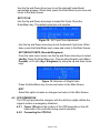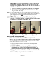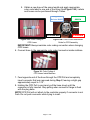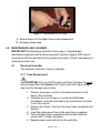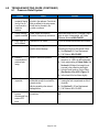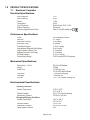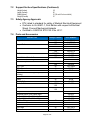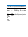
1
Sentry 1250 & Sentry 1400 Formerly ST-1200 & ST-1400 Pressure Redistribution Systems Operating Instructions Tridien Medical Revision: AO-SM-ST-02 ! WARNING Before operating this medical equipment, it is important to read this manual and to understand the operating instructions and safety precautions. Failure to do this could result in patient injury and/or damage to the product. This equipment generates uses and radiates radio frequency energy and, if not installed and used in accordance with the instructions, may cause harmful interference to other devices in the vicinity (See Section 7.5). However, there is no guarantee that interference will not occur in a particular installation. If this equipment does cause harmful interference to other devices, which can be determined by turning the equipment off and on, the user is encouraged to try to correct the interference by one or more of the following measures: Reorient or relocate the receiving device. Increase the separation between the equipment. Connect the equipment into an outlet on a circuit different from that to which other device(s) are connected. Consult with Tridien for help. If you have any questions, please contact Tridien Medical Customer Service at 800-474-4225 or 954-340-0500. Medical Electrical Equipment needs special precautions regarding Electromagnetic Compatibility (EMC) and needs to be installed and put into service according to the EMC information provided in this manual. Portable and mobile RF communications equipment can affect Medical Electrical Equipment. The use of accessories, transducers, and cables other than those specified, with the exception of transducers and cables sold by the manufacturer of this device as replacement parts for internal components, may result in increased emissions or decreased immunity of the Sentry/ST Systems. The Sentry/ST Systems should not be used adjacent to or stacked with other equipment. However, if adjacent or stacked use is necessary, the Sentry/ST Systems should be monitored to verify the product is operating as intended in whichever configuration it is being used. Page 1 of 34 TABLE OF CONTENTS Page 1.0 Safety Precautions 3 2.0 Product Overview 5 3.0 Installation 6 4.0 Operation 4.1 Control Panel 4.2 Key Functions 4.3 Additional Functions 4.4 Settings and System Information 4.5 CPR Operation 8 8 11 12 15 5.0 Maintenance and Cleaning 18 6.0 Troubleshooting Guide 22 7.0 Product Specifications 7.1 Electronic Controller 7.2 Support Surface 7.3 Safety Agency Approvals 7.4 Parts & Accessories 7.5 Product Compliance Declarations 24 25 25 25 26 8.0 Warranty Information 30 9.0 Product Return 31 REFERENCE FOR FIGURES: Figure # 1 2 3 4 5 6 7 8 9 10 11 12 13 14A, B & C 15A & B 16 17 Description Sentry/ST Control Panels Main Screen Menu Configuration Map Main Menu Screen Patient's Weight Advanced Settings Menu Set Pressure Menu Float Pressure Adjustment Set Pressure Menu AP Pressure Adjustment Fowler Boost Adjustment AP Cycle Time Adjustment Selection of Weight Units (lbs/kg) CPR Color Code of CPR Color Code of Hoses Inside Mattress Replacement of CPR Hose Page 2 of 34 Page 8 9 12 12 13 13 14 14 14 14 14 15 15 16 17 17 18 1.0 SAFETY PRECAUTIONS CAUTION! The Sentry 1250/ST 1200 & Sentry/ST-1400 Systems (“Sentry/ST Systems”) are contraindicated for use with certain medical conditions and treatments. Always consult with the patient’s physician before placing a patient on an alternating pressure system. CAUTION! Bed frames used with the Sentry/ST Systems can vary greatly depending on the specific health care setting, e.g., hospitals, nursing homes, home care. Therefore, it is the responsibility of the caregiver to take the necessary precautions to ensure the safety of the patient. This includes, but is not limited to, the appropriate use of side rails to prevent falls and/or patient entrapment. Electronic Controller: DANGER! Do not use in the presence of flammable anesthetics. Risk of explosion can result. Exposure of the electronic controller to any liquid while it is plugged in could result in a severe electrical hazard. Only use fuses that have the same specified rating (See Section 7.0 Product Specifications). Using fuses with higher ratings could result in damage and/or injury. CAUTION! Risk of Electric Shock. Do not open or attempt to repair or service the electronic controller. Repairs and service should only be done by Tridien Medical. If the controller is not functioning properly, or has been damaged, unplug the unit and take it out of service immediately. Contact Customer Service at 800-474-4225 or 954-340-0500 for repair and service information. The electronic controller is a precision electronic product. Use care when handling or transporting. Dropping, or other sudden impacts, may result in damage to the controller. Page 3 of 34 CAUTION! PE GND terminal in the appliance is only for functional earth. The unit is a Class II device with functional earth and used only for functional purposes. IMPORTANT! Do not return a product for any reason without first contacting Customer Service to obtain authorization (See Section 9.0). Do not place any objects/items, such as blankets, on, or over, the electronic controller. Excessive weight placed on the Sentry/ST System Mattress, i.e., greater than 500 pounds /226 kilograms could result in damage to the electronic controller or mattress (See Section 7.1). After exposure to extreme high or low temperatures, allow electronic controller to reach room temperature before operating. The Sentry/ST Systems circulate room air during operation. Exposure to smoke may cause the system to fail. Therefore, smoking by patients, or visitors, while using the Sentry/ST Systems is strongly discouraged. The power cord to the electronic controller should be positioned to avoid a tripping hazard and/or damage to the cord. Tridien recommends placing the cord under the bed frame and plugging it into an electrical outlet by the head of the bed. Page 4 of 34 2.0 PRODUCT OVERVIEW The Sentry/ST Systems are microcontroller-based therapeutic Pressure Redistribution Mattress Systems for patient weights up to 500 pounds/226 kilograms. The Alternating Pressure feature provides pressure relief by sequentially deflating and inflating alternate air cells on a timed interval. It is widely recognized that constant pressure to a bony prominence is the leading cause of skin breakdown. The movement of the air cells helps to alleviate these areas of constant pressure and enhances circulation. The Sentry/ST Mattress is equipped with side bolsters. Sentry 1250/ST-1200 – Integrated only Sentry/ST-1400 – Integrated and Raised The Low Air Loss (LAL) feature is available on all Sentry/ST Systems; it delivers a flow of air to the patient to aid in maintaining a temperature environment that enhances pressure wound therapy. Sentry1250/ST-1200 directs the flow through the mattress Sentry/ST-1400 uses Micro-vent™ Technology to direct the flow through the cover to the patient’s skin. The electronic controller provides a real-time display of the air pressure for both the inflated and deflated air cells. The deflated air cells provide pressure relief, while the inflated air cells support the patient’s weight. The amount of pressure needed to support a patient can be set automatically, based on the patient’s weight, or can be set manually through custom configurations in Advanced Settings. All settings are stored in memory. If the power is interrupted, the controller returns to the previous settings when the power returns, with the exception of the Alarm Mute and keypad Lock functions. IMPORTANT! The Sentry 1250/ST-1200 & Sentry/ST-1400 are all part of the same product line. However, due to specific design functions, the components are not interchangeable. Doing so may cause loss of functionality and/or unwanted alarm conditions. To aid in differentiating between the two models, each cover, mattress and controller has a label indicating the model. The zipper on the mattress and cover is also color coded. The Sentry/ST-1400 zipper is blue and the Sentry 1250/ST-1200 is black. Page 5 of 34 3.0 INSTALLATION NOTE - It is recommended that all shipping and packing material be saved in the event that the product has to be sent back to Tridien. 3.1 Unpacking and Inspection Carefully remove the controller, mattress and all accessories from the shipping cartons. Inspect all items for any damage that may have occurred during shipping. Any damages, or missing components, should be reported to Tridien Customer Service as soon as possible. Mattress Replacement – The box contains a completely assembled mattress replacement system. The mattress consists of: 1.5 Inch Foam Overlay Air Cell Assembly Top Coverlet CPR Hose Assembly LAL Hose Integrated Bolsters Raised Bolsters (Sentry/ST-1400 Only) Electronic Controller - The electronic controller is in a separate box containing: Electronic controller Power cord Operating Instructions 3.2 Installation Sentry/ST Systems are designed to operate in a controlled environment, which is free from extreme temperatures, high humidity and/or excessive amounts of airborne particulates, such as dust and smoke. 3.2.1 Mattress Replacement: 1. Remove the current mattress from the bed frame. 2. Unroll the Sentry/ST Mattress Replacement on the frame. 3. Position mattress and hoses so that the: CPR hose assembly is to the LEFT of the controller LAL hose is to the LEFT of the controller 4. There are two sets of straps with D-rings on each side of the mattress and one at the head of the mattress. Use these straps to secure the mattress replacement to the bed frame. Caution! Verify that the attachment of the mattress does not interfere with the bed movement or operation. This could result in damage to the mattress. Page 6 of 34 3.2.2 Electronic Controller: 1. Hang the controller on the TOP edge of the footboard on the bed frame. 2. Attach the hose/CPR assembly to the LEFT side of the controller (See Section 4.5). 3. Attach the LAL hose to the single connector on the LEFT side of the controller. The LAL hose should always be plugged into the controller, even when not in use. This will prevent the CPR assembly from falling to the floor when released and becoming a trip hazard in an emergency situation. 4. Plug into a grounded 115 Vac 60 Hz electrical outlet. Controller will turn on automatically and “beep” to alert caregiver that it is active. 5. To begin operation, press the POWER ON/OFF button (See Section 4.2) 6. Press Max button for rapid inflation of entire mattress. 7. Always place patient in center of mattress. NOTE - In the event of a power outage or turning the pump off, it will always come back on in the mode which was last selected. 8. Once full, you can begin patient setup. 9. During initial inflation, the integrated bolsters will fill first, followed by the alternating cells. Page 7 of 34 4.0 OPERATION 4.1 Control Panel The Sentry/ST-1400 control panel is shown in the diagram below. The control panels for the Sentry 1250/ST-1200 & Sentry/ST-1400 controller are the same except as noted below: Sentry 1250/ST1200 ONLY Figure 1: Control Panels 4.2 Key Functions The keypad has three (3) types of touch keys: 1. Function Keys: Sentry/ST-1400: Therapy, Max, Fowler, LAL and Inflate Bolsters Sentry 1250/ST-1200: Alternating Pressure, Float, Max, Fowler & LAL 2. Settings Keys: Menu, Up and Down Keys 3. Feature Keys: Power ON/OFF, Lock, Alarm Mute Page 8 of 34 POWER ON/OFF (All Sentry/ST Systems) When the power cord is first inserted in the AC socket on the back cover, the unit goes into Standby Mode and a green LED will blink every 3 seconds until the POWER ON/OFF button is pressed. Press the POWER ON/OFF button to start system operation. The Main Screen shown in Figure 2 will appear. However, the pressure reading will vary from the figure below. Figure 2: Main Screen The second line shows three fields: The set pressure for Zones A and B The real-time pressure in Zone A The real-time pressure in Zone B. Set pressure may be increased or decreased by pressing the Up or Down keys, respectively. MAXIMUM INFLATE (All Sentry/ST Systems) This key activates or deactivates the MAXIMUM INFLATE mode. When activated, the screen displays Max and all mattress cells are inflated to 50 mmHg to provide a firm, flat surface. This mode will last for approximately 20 minutes, unless turned off by pressing the MAX key again. The system will then revert back to the previously set operating mode. The mattress MAX pressure value is not adjustable. Page 9 of 34 LOW AIR LOSS (All Sentry/ST Systems) This key activates or deactivates the LAL feature. When activated, LAL is shown on the display and a gentle diffused flow of air is delivered through the LAL coverlet (Sentry/ST-1400), or the mattress (Sentry 1250/ST1200). The air will begin to flow only after the mattress has reached the set pressure, either after initial installation or in any mode such as AP, Float, or MAX. The air flow will also be temporarily interrupted while the raised bolster is inflating. THERAPY (Sentry/ST-1400 System) This key selects the ALTERNATING PRESSURE RELIEF (AP) or AIR FLOTATION (Flt) mode. The screen display toggles between Flt and AP. NOTE! The Sentry 1250/ST-1200 has separate keys for these two therapies. FOWLER BOOST (All Sentry/ST Systems) This key activates or deactivates the FOWLER BOOST (FB) mode. When activated, FB is shown on the display and the set pressure in the mattress is automatically increased by a set percentage. It is not available when the system is in Maximum Inflate mode. The percentage of increase may be modified by going to ADVANCED SETTINGS. (See Section 4.4.2) This feature helps prevent a patient from “bottoming out” when he or she is put into an inclined or “Fowler” position. INFLATE BOLSTERS (Sentry/ST-1400 System) This key inflates or deflates only the raised side bolsters. When activated, Inf is shown on the display and the bolsters will take approximately (1) minute to inflate. Page 10 of 34 Inflating these bolsters increases bolster height on the sides of the mattress. Integrated bolsters and raised bolsters are inflated to 60 mmHg. This value is not adjustable. 4.3 Additional Functions LOCK KEYPAD (All Sentry/ST Systems) This key locks all keys, including the Power ON/OFF key. Press and hold for 2 seconds to activate. The corresponding blue LED is lit. Press and hold for 2 seconds to unlock. In the event of a power outage or being unplugged, the Lock function will deactivate and must be reset when power is restored. ALARM FUNCTION The Sentry/ST System is equipped with an audible alarm to alert the user that the actual pressure in the air cells is below or above the set pressure. An error message will also appear on the display instructing the user to “Check Air Cells”. This will happen in approximately 10 minutes. The alarm and error message will continue until the problem is resolved, unless in AP mode. See NOTE below. NOTE: In AP mode, once the problem is resolved, it takes two cycles for the alarm to stop. The unit may also be turned off for 10 seconds and turned back on to reset the alarm more quickly. Refer to Troubleshooting guide for further instructions. See Section 6.0 AUDIBLE ALARM MUTE (All Sentry/ST Systems) This key mutes the AUDIBLE ALARM. When the ALARM MUTE key is pressed, the AUDIBLE ALARM cannot be heard, but an error message continues to flash on the display and a solid blue LED activates. If the alarm condition is not resolved within 15 minutes the audible alarm will reactivate. In the event of a power interruption, the Alarm Mute function will deactivate. (See Troubleshooting Guide in Section 6.0). Page 11 of 34 4.4 Settings and System Information (All Sentry/ST Systems) MENU Press this key to enter the MAIN MENU options screen. Once in the Main Menu, use the ARROW keys to select the desired option and then press the MENU key a second time to save the selected option. ARROWS ARROW keys moves the selection arrow up or down one row at a time and are also used to increase/decrease numerical values. 4.4.1 Menu Configuration Map MAIN MENU LEVEL 1 PATIENT SETUP LEVEL 2 Float Set Pressure AP Set Fowler ADVANCED Set Cycle Exit lbs UNITS Kg Exit EXIT Figure 3: Menu Configuration Map 4.4.2 Main Menu While the unit is showing the Main Screen (Figure 2) pressing the Enter/Menu key shows the Main Menu screen (See Figure 4). Figure 4: Main Menu Screen Page 12 of 34 1. Patient Setup This option is used to set the patient’s weight. The Controller automatically adjusts the pressure values for Float and Alternating Pressure modes based on the patient’s weight. Resetting the patient’s weight at any time will override any user changes to AP and/or Float Pressures entered directly on the main screen or through the Advanced Settings. However, Fowler Boost and Cycle Time do not reset. They must be adjusted manually. By default, Fowler Boost is 20% and Cycle time is 6 minutes. Figure 5: Patient's Weight Use the Up and Down arrows to set the patient’s weight. When done, press the Enter/Menu key to save and return to the main screen. 2. Advanced settings This option is used to customize settings such as Mattress Pressures, percentage of Fowler Boost increase and AP Cycle time. From the Main Menu screen (Figure 4) select Advanced. The Advanced Menu will appear. (Figure 6) SET PRESSURE Figure 6: Advanced Settings Menu Use the Up and Down arrow keys to select the desired feature. Press the Enter/Menu key to select “Set Pressure” in order to adjust Float and AP pressures. Page 13 of 34 SET FLOAT Figure 7: Set Pressure Menu Figure 8: Float Pressure Adjustment Use the Up and Down arrow keys to select Float. Press the Enter/Menu key. Once Float is selected, (Figure 8), use the Up and Down arrow keys to set the desired float pressure. When done, press the Enter/Menu key to save and return to the Main Screen. SET AP Figure 9: Set Pressure Menu Figure 10: AP Pressure Adjustment Use the Up and Down arrow keys to select AP. Press the Enter/Menu key. Once AP is selected, (Figure 10), use the Up and Down arrow keys to set the desired AP pressure. When done, press the Enter/Menu key to save and return to the Main Screen. SET FOWLER Use the Up and Down arrow keys to select Set Fowler. Press the Enter/Menu key. Figure 11: Fowler Boost Adjustment Page 14 of 34 Use the Up and Down Arrow keys to set the desired Fowler Boost percentage increase. When done, press the Enter/Menu key to save and return to the Main Screen. SET CYCLE Use the Up and Down arrow keys to select Set Cycle. Press the Enter/Menu key. The default cycle time is 6 minutes. Figure 12: AP Cycle Time Adjustment Use the Up and Down arrow keys to set the desired Cycle time. When done, press the Enter/Menu key to save and return to the Main Screen. SET WEIGHT UNITS (Pounds/Kilograms) From the main menu screen use the Up and Down arrow keys to select Lbs/Kg. Press the Enter/Menu key. Choose either English units (Lbs = Pounds), or SI units (Kg = Kilograms) by using the up and down arrow keys. Figure 13: Selection of Weight Units Press the Enter/Menu key to save and return to the Main Screen. EXIT Select this option to make no changes and return to the Main Screen. 4.5 CPR OPERATION The CPR pull provides the caregiver with the ability to rapidly deflate the support surface in emergency situations. 4.5.1 Figure 14A shows the location of the CPR assembly on the left lower side of the controller during normal operation. 4.5.2 Connecting the CPR Pull Page 15 of 34 IMPORTANT! The CPR pull is designed to attach to the controller with a specific orientation. Make sure you align the CPR pull key with the CPR receptacle on the controller and that the CPR label is visible from the front: 1. 2. ALWAYS align the CPR “key” with the key on CPR receptacle. Completely insert the CPR pull until a “click” is heard. (See Figures 14A, 14B, 14C). 4.5.3 To release the CPR pull, place your thumb and opposing finger on the release tabs located on the TOP and BOTTOM of the CPR pull and completely depress both tabs simultaneously as shown in Figure 14B. 4.5.4 With both tabs depressed, pull the CPR pull away from the controller to deflate the mattress. The rate of deflation is dependent on the weight of the patient. (See Figure 14C). Figure 14A Figure 14B Figure 14C 4.5.5 CPR Hose Replacement/Repair Follow the steps below for proper CPR hose replacement: NOTE: The CPR hoses are color coded for ease of replacement. It is very important to reconnect the hoses in the proper location for the Sentry/ST SYSTEM to function correctly. 1. Remove the CPR Pull from the controller according to Step 4.5.3-4.5.4 above. 2. Hold the CPR Pull in one hand and pull the hose needing replacement until the white connector and hose separate and come loose from the CPR. Retain connector to re-use in Step 7. 3. Remove the other end of the hose from the connector inside the mattress. 4. Remove tubing wrap and discard unwanted hose. Page 16 of 34 5. Obtain a new hose of the same length and apply appropriate color code label to one end of the hose (See Figure 15A). Labels and hoses can be purchased through Tridien. Integrated Bolster BLUE Raised Bolster GREEN KEY B Zone BLACK Figure 15A: Color-Coding of CPR Hoses A Zone RED Figure 15B: Color-Coded Attachment Guide for CPR Assembly IMPORTANT! Always maintain color coding convention when changing CPR hoses. 6. Connect hose to the appropriate color coded connector inside mattress. Figure 16: Color-Coding of CPR Hoses Inside Mattress 7. Feed opposite end of the hose through the CPR Pull and completely insert connector that was removed during Step 2, leaving a slight gap approximately equal to 1/10’’. 8. Holding the CPR Pull in one hand, pull the hose slowly until the connector is fully inserted. Stop pulling when connector flange is flush with the plug base. NOTE! CPR Pull will not attach to the controller properly if connector is not flush. Do not push connector while trying to insert. Page 17 of 34 Figure 17: Replacement of CPR Hose 9. Repeat steps 2-8 if multiple hoses need replacement. 10. Re-apply tubing wrap. 5.0 MAINTENANCE AND CLEANING IMPORTANT! All disinfection should be done using a “hospital-grade” disinfectant registered with the Environmental Protection Agency (EPA) and in accordance with the manufacturer’s specified instructions. Check manufacturer’s instructions before use. 5.1 Electrical Controller The electronic controller is easy to maintain: 5.1.1 Fuse Replacement CAUTION! Only use UL/ETL-Approved fuses that have the same rating as specified (See Section 7.0). Using fuses with higher ratings may result in damage and/or injury: 1. Remove the power cord from the electrical socket on the back of the controller. 2. Using the tip of your finger or a small sized flat-head screwdriver, push the small tab on the fuse drawer and slide it out of the socket. 3. Remove the “blown” fuse from the fuse holder receptacle and discard. 4. Insert the replacement fuse in the same fuse receptacle. 5. Push the fuse holder completely back into the electrical socket until it “snaps” into place. 6. Replace power cord and turn on the controller. Page 18 of 34 5.1.2 The exterior of the controller and CPR assembly should be periodically wiped down with a cloth dampened with disinfectant. CAUTION! DO NOT spray disinfectant directly on the electrical controller, or immerse the controller in any type of liquid. This could result in a severe electrical hazard. 5.1.3 Before plugging in the controller, check the power cord for electrical hazards, e.g., cuts, exposed wires, worn insulation, etc. If hazards are present, take the controller out of operation immediately and contact Tridien Customer Service at 800-4744225 or 954-340-0500. 5.1.4 To ensure optimal performance, calibration and Bio-Med testing of your Sentry/ST System, should be performed at least annually. Contact Tridien Customer Service for calibration and Bio-Med information. Tridien will provide one free Bio-Med test. 5.1.5 Filter Maintenance 5.1.5.1 The filter is removable and can be changed when necessary. A spare parts list can be found on page 25 or at Tridien.com. 5.1.5.2 The filter on the bottom of the controller should be checked periodically and cleaned as needed. A standard vacuum hose with a brush attachment should be used to clean the filter. 5.1.5.3 To remove or replace the filter, follow the steps below: 1. Unplug the electronic controller. 2. Remove the filter grill cover and remove the filter. DO NOT unscrew the filter assembly. 3. Clean the filter by washing in a mild detergent and allow to air dry. 4. Insert the filter back into the filter housing and replace the grill cover. 5. If the filter cannot be cleaned or becomes damaged, contact Tridien Customer Service for replacement filters. IMPORTANT! Good filter maintenance is critical in keeping your Sentry/ST controllers in optimal operating condition. Failure to keep the filter clean will result in system downtime and increased repair costs 5.2 Coverlet 5.2.1 Washing and Disinfecting If there are visible signs of body fluids and/or substances present, coverlets should be washed between patients. Coverlets can be machine-washed using chlorine bleach (50-150ppm) or Page 19 of 34 an intermediate level disinfectant, such as ProTech1. Bleach and disinfectant should be used according to the manufacturer’s instructions. To determine the amount of bleach or disinfectant to use, determine the amount of water in the washer and then follow the manufacturer’s dilution instructions. Soak the coverlet in the disinfectant or bleach during the wash cycle. Rinse thoroughly in clean water and dry before use. NOTE! 2.5 ounces of bleach per 10 gallons of water is approximately 100ppm of available chlorine. CAUTION! Heat will severely damage the material. DO NOT dry the coverlet using the “heat” cycle. Air dry, or use a “non-heat” dry cycle, e.g., air fluff. 5.2.2 Washing Alternative If there are no visible signs of body fluids and/or substances present, the coverlet can be sanitized between patients. To sanitize the coverlet: 1. Apply chlorine bleach, or an intermediate level disinfectant at the appropriate dilution (See Section 5.2.1) to the upper surface of the coverlet. Bleach/disinfectant may be applied either by spraying or by hand application. 2. Ensure surface is completely covered with the bleach/disinfectant. 3. Allow bleach/disinfectant to remain in contact with the surface according to the manufacturer’s instructions. 4. Remove bleach/disinfectant and rinse. 5. Allow to air dry before use. 5.3 Outside Shell Wipe down with disinfectant, ensuring that all surfaces come in contact with the disinfectant. Rinse off with a clean damp cloth and allow to air dry. Inspect straps and fasteners for signs of wear and tear and replace if needed. 5.4 Air Cell Assembly CAUTION! DO NOT machine wash or dry the air cells. 1 ProTech® is a tuberculocidal disinfectant cleaner and a registered trademark of Central Solutions, Inc. Page 20 of 34 The air cell assembly does not routinely need to be cleaned or disinfected between patients. If cleaning/disinfection is required, follow instructions in Section 5.2.2 above. All air cells, including the bolsters are fully accessible and easily replaced. 5.5 Foam Overlay The foam mattress is fully enclosed in a urethane cover and should not require cleaning. However, if it does become “visibly” soiled, it may be wiped down with disinfectant, ensuring that all surfaces come in contact with the disinfectant. Wipe off with a clean damp cloth and allow to air dry. CAUTION! DO NOT machine wash or dry the Foam Overlay. 5.6 CPR The exterior of the CPR assembly can be periodically wiped using a cloth dampened with disinfectant. The CPR sleeve can be machine washed but must be re-attached to protect CPR Assembly. This will ensure that in the event the CPR pull is released, it will not fall to the floor and become a trip hazard in an emergency situation. 5.7 Spare Parts A spare parts list can be found on page 25 or at Tridien.com. NOTE! You must be certified by Tridien to perform most controller repairs. Contact Customer Service for more information. Page 21 of 34 6.0 TROUBLESHOOTING GUIDE 6.1 Pressure Relief System Problem Cause Solution 1. Alarm is on The air cell alarm is activated any time the actual pressure in the air cells does not reach the programmed set pressure in approximately 10 minutes. The alarm will activate if the actual pressure is beyond the tolerance of 2mmHg greater or lower than the set pressure. Low pressure is usually an indication of an air leak in the system. High pressure is usually an indication of a kinked hose. a) It can be muted temporarily by pressing the Alarm Mute button but, the condition must be resolved before it will turn off permanently. b) Check the CPR connections (See Section 4.5); make sure all male fittings have o-rings in place and are not worn/cut and all CPR fittings are set properly inside the CPR assembly (See Section 4.5). c) Check that all hoses are properly connected according to the corresponding color-coding on the controller & are not kinked or cut. d) Check all hoses for cuts, holes or kinks along the inside of the mattress. Each hose should also be tightly connected to their respective connector or air cell. e) Check each air cell for cuts or holes to ensure there are no leaks. (It will be easier to detect a possible leak if you place the system in the MAX INFLATE mode). f) Once the leak or kink has been resolved, the alarm will automatically turn off. To reset the system more quickly, turn the power off and then on again to reset. 2. The controller is clicking excessively Hose may be kinked Starting at the CPR, check all hoses inside and outside of the mattress for kinks. 3. The pressures may be set too low for the patient’s weight. a) Verify weight setting in Patient Setup. See Section 4.4.2. Adjust if set weight is not accurate to the patient’s actual weight. b) Increase bed pressure by pressing the FOWLER button on the control panel. The amount of this increase can be modified in Advanced Settings and 3-5mmHg is usually sufficient. However, wait at least 10 minutes between adjustments to review patient support condition in order to prevent excessive pressure. c) Use the UP arrow key on the control panel to make small incremental changes in pressure. However, wait at least 10 minutes between adjustments to review patient support condition in order to prevent excessive pressure. Patient is sinking or “bottoming out” Page 22 of 34 6.0 TROUBLESHOOTING GUIDE (CONTINUED) 6.1 Pressure Relief System Problem 4. Air is not constantly flowing into the Low Air Loss Coverlet or inside the mattress Cause Solution The internal pump gives priority to the Allow air cells to reach set pressure. air cells in the mattress. Once the air cells are inflated to the set pressure, air will then be directed to the coverlet or mattress. 5. Display readings appear scrambled Power surges can cause the controller to temporarily malfunction. Disconnect power cord for 10 seconds, plug in again to reset. If unsuccessful, call Tridien Customer Service at 800-474-4225. 6. Every other air cell is deflated Controller is in AP mode This is the normal function while in this mode. 7. Power loss Facility power outage, blown fuse, or possible internal damage. Our unique design will close each valve, preventing air loss for a short period of time. a) See Section 5.1.1 Fuse Replacement b) Call Tridien at 800-474-4225. 8. Patient is uncomfortable or mattress feels lumpy Excess or insufficient pressure. a) Make sure controller is plugged in and turned on, i.e.: LED is on and solid green. b) Verify weight setting in Patient Setup. See Section 4.4.2. Adjust if set weight is not accurate to the patient’s actual weight. c) Activate Fowler mode on Control Panel (See Section 4.2 or 4.2.2 & Figure 11) d) Incline head of the bed frame slightly. 9. Controller is inoperable May be caused by a power surge substantial enough to overload the internal circuitry. May be caused by other internal damage/failure. a) Check fuse on power cord socket by opening the fuse compartment on side of controller. b) See Section 5.1.1 Fuse Replacement c) Call Tridien at 800-474-4225. 10. CPR hoses Excessive force applied to hose become connections. disconnected from exterior CPR block Page 23 of 34 Reconnect in correct orientation. See Section 4.5. 7.0 PRODUCT SPECIFICATIONS 7.1 Electronic Controller Electrical Specifications: Input Voltage AC Input Frequency Current Consumption Circuit Protection Mode of Operation Protection Against Electric Shock 115V 60 Hz 1.75A <60W Double Fused, 250V, 3.15A Continuous Class II, Type BF applied part Performance Specifications: Zones Max Flow Max Inflate Pressure Max Inflate Timer Float Mode Pressure Integrated and Extended Side Bolsters Support Surface Inflation Time Alternate Pressure Cycle Range AP Mode Pressure Patient Weight Range 2 for Alternating Pressure 25 ~ 40lpm 50 ± 2mmHg 20 minutes 5 - 25 ± 2 mmHg 60 ± 2 mmHg 5~10 minutes 4 –15 minutes 8 – 43 ± 2 mmHg 50-500 pounds (22-226 kilograms) Mechanical Specifications: Dimensions, L x W x H Weight Power Cord 5.5 x 9.4 x10.5 inches 10.5 lbs 13’ (396 cm) Long 16~18 AWG Hospital Grade ¼” flow quick couplings 1 Piece per Box 1.5 x 1.5 in Polyester Filtering Felt Connection Packaging Air Filter Environmental Specifications: Operating Conditions: Ambient Temperature 40 oF to 104 oF 10 oC to 40 oC 30% to 75% Non-Condensing 700 hPa to 1060 hPa Relative Humidity Atmospheric Pressure Storage and Shipping Conditions: Ambient Temperature -40 oF to 158 oF 40 oC to 70 oC 10% ≥ 100% 500 hPa to 1060 hPa IPX0 Relative Humidity Atmospheric Pressure Liquid Ingress Protection Page 24 of 34 7.2 Support Surface Specifications (Continued): Height (Inches) Length (Inches) Width (Inches): Weight (Pounds) 7.3 6.5 80 36 (39 and 42 also available) 30 Safety Agency Approvals: ETL Listed to standard for safety of Medical Electrical Equipment Conforms to UL 60601-1, First Edition with respect to Electrical Shock, Fire and Mechanical Hazards Certified to CAN/CSA STD C22.2 No. 601.1 7.4 Parts and Accessories DESCRIPTION Support Surface Controller Sentry/ST MODEL 1250 1400 1250 1400 1250 1400 1250/1200 1400 1400 Support Surface Coverlet Shell Raised Bolster, Patient Left Raised Bolster, Patient Right CPR Assembly CPR – Pull CPR – Connector CPR – Hoses CPR – Color Code Labels (specify color when ordering) CPR Hose Sleeve Snaps Main Air Cell Trunk Air Cell Loop Assembly Integrated Bolster, Head, Patient Left Integrated Bolster, Head, Patient Right Integrated Bolster, Foot, Patient Left Integrated Bolster, Foot, Patient Right LAL Hose Fitting Power Cord AC Inlet Fuse (2) Filter Hinge Filter 1250/1200 1400 All All All All All All All Sentry 1250/Sentry 1400 Sentry 1250/Sentry 1400 All All All All All All Page 25 of 34 PART NUMBER 12-SM50-R 14-SM00-R 44-SM0003-R 44-SM0002-R 44A-0004-R 44A-0003-R 44A-0005 44A-0023 44A-0011 44A-0010 44A-0025 44A-0024 DP-P10604 CQ-MB4 CH-V3 IP-0001 44A-0022 HF-H9 44A-0009 44A-0051 44A-0052 44A-0012 44A-0013 44A-0014 44A-0015 CQ-MP5E EH-CO1 ES-F-3 DS-P10210 MF-F60-W 7.5 Product Compliance Declarations 7.5.1 Guidance and Manufacturer’s Declaration – Electromagnetic Emissions Guidance and Manufacturer’s Declaration – Electromagnetic Emissions The Sentry/ST System is intended for use in the electromagnetic environment specified below. The customer or the user of the Sentry/ST System should assure that it is used in such an environment. Emissions test Compliance Electromagnetic environment – guidance The Sentry/ST System uses RF energy only for its internal function. Therefore, its RF emissions are very low and are not likely to cause any interference in nearby electronic equipment. RF emissions CISPR 11 Group 1 RF emissions CISPR 11 Class A Harmonic emissions IEC 61000-3-2 Not Applicable Voltage fluctuations / flicker emissions IEC 61000-3-3 Not Applicable The Sentry/ST System is suitable for use in all establishments other than domestic and those directly connected to the public low-voltage power supply network that supplies buildings used for domestic purposes. Page 26 of 34 7.5.2 Guidance and Manufacturer’s Declaration – Electromagnetic Immunity Guidance and Manufacturer’s Declaration – Electromagnetic Immunity The Sentry/ST System is intended for use in the electromagnetic environment specified below. The customer or the user of the Sentry/ST System should assure that it is used in such an environment. IEC 60601 test Compliance Electromagnetic environment Immunity test level level – guidance Floors should be wood, concrete Electrostatic ±6 kV contact ±6 kV contact or ceramic tile. If floors are discharge (ESD) covered with synthetic material, ±8 kV air ±8 kV air the relative humidity should be at IEC 61000-4-2 least 30 %. ±2 kV for power Mains power quality should be supply lines ±2 kV for power Electrical fast that of a typical commercial or supply lines transient/burst hospital environment. ±1 kV for input/output Not Applicable IEC 61000-4-4 lines ±1 kV line(s) to ±1 kV line(s) to Mains power quality should be line(s) line(s) Surge that of a typical commercial or hospital environment. ±2 kV line(s) to ±2 kV line(s) to IEC 61000-4-5 earth earth <5 % UT <5 % UT Mains power quality should be Voltage dips, (>95 % dip in (>95 % dip in UT) that of a typical commercial or short UT) for 0,5 cycle hospital environment. If the user interruptions and for 0,5 cycle of the Sentry/ST System requires voltage variations 40 % UT continued operation during power on power supply 40 % UT (60 % dip in UT) mains interruptions, it is input lines IEC (60 % dip in UT) for 5 cycles recommended that the 61000-4-11 for 5 cycles Sentry1250/ST-1200/1400 70 % UT controller be powered from an 70 % UT (30 % dip in UT) uninterruptible power supply or a (30 % dip in UT) for 25 cycles battery. for 25 cycles <5 % UT <5 % UT (>95 % dip in UT) (>95 % dip in for 5 sec UT) for 5 sec Power frequency magnetic fields Power frequency should be at levels characteristic (50/60 Hz) 3A/m 3A/m of a typical location in a typical magnetic field commercial or hospital IEC 61000-4-8 environment. NOTE:UT is the a.c. mains voltage prior to application of the test level. Page 27 of 34 7.5.3 Guidance and Manufacturer’s Declaration – Electromagnetic Immunity - Non Life Supporting Guidance and Manufacturer’s Declaration – Electromagnetic Immunity The Sentry/ST System is intended for use in the electromagnetic environment specified below. The customer or the user of the Sentry/ST System should assure that it is used in such an environment. Immunity IEC 60601 test Compliance Electromagnetic environment – guidance test level level Portable and mobile RF communications equipment should be used no closer to any part of the Sentry/ST System, including cables, than the recommended separation distance calculated from the equation applicable to the frequency of the transmitter. Recommended separation distance Conducted 3 Vrms 3 Vrms d 1.2 P RF 150 kHz to 80 IEC MHz 61000-4-6 d 1.2 P 80 MHz to 800 MHz 3 V/m 3 V/m d 2.3 P 800 MHz to 2,5 GHz Radiated 80 MHz to 2,5 RF GHz Where P is the maximum output power rating IEC of the transmitter in watts (W) according to 61000-4-3 the transmitter manufacturer and d is the recommended separation distance in metres (m). Field strengths from fixed RF transmitters, as determined by an electromagnetic site survey, a should be less than the compliance level in each frequency range. b Interference may occur in the vicinity of equipment marked with the following symbol: NOTE 1: At 80 MHz and 800 MHz, the higher frequency range applies. NOTE 2: These guidelines may not apply in all situations. Electromagnetic propagation is affected by absorption and reflection from structures, objects and people. a b Field strengths from fixed transmitters, such as base stations for radio (cellular/cordless) telephones and land mobile radios, amateur radio, AM and FM radio broadcast and TV broadcast cannot be predicted theoretically with accuracy. To assess the electromagnetic environment due to fixed RF transmitters, an electromagnetic site survey should be considered. If the measured field strength in the location in which the Sentry/ST System is used exceeds the applicable RF compliance level above, the Sentry/ST System should be observed to verify normal operation. If abnormal performance is observed, additional measures may be necessary, such as re-orienting or relocating the Sentry/ST System. Over the frequency range 150 kHz to 80 MHz, field strengths should be less than 3 V/m. Page 28 of 34 7.5.4 Recommended Separation Distances Recommended Separation Distances Between Portable And Mobile RF Communications Equipment And The Sentry1250/ST-1200/1400 The Sentry/ST System is intended for use in an electromagnetic environment in which radiated RF disturbances are controlled. The customer or the user of the Sentry/ST System can help prevent electromagnetic interference by maintaining a minimum distance between portable and mobile RF communications equipment (transmitters) and the Sentry/ST System as recommended below, according to the maximum output power of the communications equipment. Rated Separation distance according to frequency of transmitter maximum M output 150 kHz to 80 MHz 80 MHz to 800 MHz 800 MHz to 2,5 GHz power of transmitter d 1.2 P d 1.2 P d 2.3 P W 0.12 0.12 0.23 0,01 0.38 0.38 0.73 0,1 1.2 1.2 2.3 1 3.8 3.8 7.3 10 12 12 23 100 For transmitters rated at a maximum output power not listed above, the recommended separation distance d in metres (m) can be estimated using the equation applicable to the frequency of the transmitter, where P is the maximum output power rating of the transmitter in watts (W) according to the transmitter manufacturer. NOTE 1: At 80 MHz and 800 MHz, the separation distance for the higher frequency range applies. NOTE 2: These guidelines may not apply in all situations. Electromagnetic propagation is affected by absorption and reflection from structures, objects and people. Page 29 of 34 8.0 WARRANTY INFORMATION LIMITED WARRANTY Tridien Medical (“Tridien”) warrants each of its products to perform in accordance with established specifications for the following time periods, starting from the date the product was shipped from the Tridien facility. Stage IV & Millennium Systems Compressor Pump: 3 Years Electronic Controller: 2 Years Soft Goods: 1 Year Sentry 1250/ST-1200, Sentry/ST-1400, Primary Care, Sentry & Air Chair Systems Compressor Pump: 2 Years Electronic Controller: 1 Year Soft Goods: 1 Year Battery: 6 Months Recliner Chair: 2 Years During the warranty period, Tridien will (at Tridien’s discretion) repair or replace at no charge any products that are not performing in accordance with established specifications, unless the problem/failure is due to customer damage, negligence and/or misuse or unauthorized repairs. Items not covered under warranty include, but are not limited to: stains, punctures, cuts, damages to electrical cords, rips or tears, dents and/or lost/missing parts. All products returned for warranty repairs must be assigned a return authorization number, prior to return. Returns should include information describing the problem and/or requested repair and be sent to Tridien by prepaid transportation. Tridien will return the repaired/replaced product at no charge. Warranty repairs do not extend the length of the warranty period. During the warranty period, Tridien will provide one Bio-Med test at no charge, excluding shipping/handling. If sending unit in solely for the free Bio-Med test, please state this when calling. Neither Tridien, its officers, directors, employees nor its agents shall be liable for consequential or other damages, including but not limited to personal injury, loss, or any other expense, directly or indirectly arising from the use of its products. The sole remedy for breach of the limited warranty granted herein shall be repair or replacement of the Tridien products. All product specifications are subject to change without notice. Page 30 of 34 9.0 PRODUCT RETURN The Sentry/ST Systems have been designed to provide you with years of trouble-free service. However, in the event that the product needs to be returned for any reason, such as calibration or repair, the following return procedure must be followed. Failure to follow this procedure may result in unnecessary delays. Return Procedure Before returning a product to Tridien: 1. Contact Customer Service at 800-474-4225 or 954-340-0500 and obtain a Return Material Authorization (RMA) number. 2. Package the product in its “approved” packaging. 3. Reference RMA number on the shipping container and shipping documents. 4. Ship product to the attention of Customer Service at the following address: Tridien Medical 4200 NW 120th Avenue Coral Springs, FL 33065 Attention: Customer Service / RMA < # > Page 31 of 34 Notes Page 32 of 34 Notes Page 33 of 34 Notes Page 34 of 34 Tridien Medical th 4200 NW 120 Avenue Coral Springs, FL 33065 Phone: 954-340-0500 FAX: 954-340-0511 Web Site: tridien.com