1
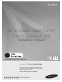
RCMHXGA RCMHXEA Air to Water Heat Pump Mono Outdoor Unit installation manual imagine the possibilities Thank you for purchasing this Samsung product. To receive more complete service, please register your product at www.samsung.com/register E S F I P D G R DB98-00000A(1) Contents Safety Precautions....................................................................................................................................................................................................................2 Product Specifications . .........................................................................................................................................................................................................4 Application Examples .......................................................................................................................................................................................................... 7 Main Components ................................................................................................................................................................................................................. 9 Functional Diagram............................................................................................................................................................................................................. 13 Installing the Unit ............................................................................................................................................................................................................... 15 Piping Work.............................................................................................................................................................................................................................. 22 Wiring ....................................................................................................................................................................................................................................... 29 Testing operations . ............................................................................................................................................................................................................ 35 Trouble shooting . ............................................................................................................................................................................................................... 37 Maintenance .......................................................................................................................................................................................................................... 38 Safety precautions Carefully follow the precautions listed below because they are essential to guarantee the safety of the equipment. WARNING • Always disconnect a power supply of Air-Water Heat Pump before servicing it or accessing components inside the unit. • Verify that installation and testing operations shall be performed by qualified personnel. • To prevent serious damage on the system and injuries to users, precautions and other notices shall be observed. Warning Carefully read the content of this manual before installing the air to water heat pump and store the manual in a safe place in order to be able to use it as reference after installation. For maximum safety, installers should always carefully read the following warnings. Store the operation and installation manual in a safe location and remember to hand it over to the new owner if the air conditioner is sold or transferred. Store the user and installation manual in a safe location and remember to hand it over to the new owner if the air to water heat pump is sold or transferred. This manual explains how to install Air-Water Heat Pump. The use of other types of units with different control systems may damage the units and invalidate the warranty. The manufacturer shall not be responsible for damages arising from the use of non compliant units. The air conditioner is compliant with the requirements of the Low Voltage Directive (72/23/EEC), the EMC Directive (89/336/EEC) and the Directive on pressurized equipment (97/23/EEC). The manufacturer shall not be responsible for damage originating from unauthorized changes or the improper connection of electric and hydraulic lines. Failure to comply with these instructions or to comply with the requirements set forth in the “Operating limits” table, included in the manual, shall immediately invalidate the warranty. Do not use the units if you see some damages on the units and recognize something bad such as loud noisy, smell of burning. In order to prevent electric shocks, fires or injuries, always stop the unit, disable the protection switch and contact SAMSUNG’s technical support if the unit produces smoke, if the power cable is hot or damaged or if the unit is very noisy. Always remember to inspect the unit, electric connections, refrigerant tubes and protections regularly. These operations shall be performed by qualified personnel only. The unit contains moving parts and electrical parts, which should always be kept out of the reach of children. 2 Do not attempt to repair, move, alter or reinstall the unit by unauthorized personnel, these operations may cause product damage, electric shocks and fires. Do not place containers with liquids or other objects on the unit. All the materials used for the manufacture and packaging of the air to water heat pump are recyclable. The packing material and exhaust batteries of the remote controller(optional) must be disposed of in accordance with local regulations. The air to water heat pump containing a refrigerant must be disposed in authorized center or returned to retailer as special wastes. Wear protective gloves to unpack, move, install, and service the unit to avoid your hands being injured by the edge of the parts. Do not touch the internal parts (water pipes, refrigerant pipes, heat exchangers, etc) while running the units. And if you need to adjust and touch the units, have enough time for the unit can be cooled and be sure to wear protective gloves. In case of refrigerant leakage, try to avoid getting in contact with the refrigerant because this could result in severe wounds. When you install the Air to water heat pump in a small room, you must consider a proper ventilation to prevent a leakage level within the maximum permissible limit. - In that case, you may die from suffocation by some possibility. Make sure to safely dispose of packing materials. Packing materials, such as nails and other metal or wooden pallets may cause children get injured. Inspect the product shipped and check if damaged during transport. If the product has some damages, DO NOT INSTALL and immediately discuss about the damages with the carrier or retailer (if the installer or the authorized technician has collected the material from the retailer.) Our units shall be installed in compliance with the spaces described in the installation manual, to ensure accessibility from both sides and allow repairs or maintenance operations to be carried out. If the units installed without complying with procedures described in manual, additional expenses can be asked because special harnesses, ladders, scaffolding or any other elevation system for repair service will NOT be considered part of the warranty and will be charged to the end customer. Always make sure that the power supply is compliant with local safety standards. Verify that the voltage and frequency of the power supply comply with the specifications and input power is sufficient to ensure the operation of any other domestic appliance connected to the same electric lines. Always verify that the cut-off and protection switches are suitably selected. Always verify that electric connections (cable entry, section of leads, protections…) are compliant with the electric specifications and with the instructions provided in the wiring scheme. Always verify that all connections comply with the standards applicable to the installation of air to water heat pumps. Devices disconnected from the power supply should be completely disconnected in the condition of overvoltage category. Do not connect the earth wire to the gas pipe or water pipe, lighting rod, surge absorber, or telephone earth wire. If earthing is not complete, it may cause an electric shock or fire. Be sure to install both an earth leakage detector and circuit breaker with specified capacity in accordance with relevant local and national regulations. - If it is not installed properly, it may cause electric shocks and fire. Make sure that the condensed water runs well out of the unit at low ambient temperature. Drain pipe and cond heater can frost/ ice can not grow. If drain work is not effective for releasing condensed water, it can make the units get damaged by massive ice and system can be stop , covered by ice. Install the power cable and communication cable of the indoor and outdoor unit at least 1m away from the electric appliance. Protect the unit from rats or small animals. If an animal makes a contact with the electric parts, it can cause malfunctions, smoke or fire. Please instruct the customer to keep the area around the unit clean. ENGLISH 3 Product Specifications Product Line-up Line-up Remark Chassis Heat Pump Units - Model Name RC120MHXEA RC120MHXGA RC140MHXEA RC140MHXGA RC160MHXEA RC160MHXGA RC090MHXEA MIM-E03A Auxiliary Parts Requisite Control Kit Standard models: NH200CHXEA NH300CHXEA Option Domestic Hot Water tank Solar connected NH200CHXES NH300CHXES Accessories Keep supplied accessories until the installation is finished. Hand the installation manual over to the customer after finishing installation. The quantities are indicated in parentheses. Installation manual (1) 4 Drain plug (1) Fastener-nut(1) Rubber-cover wire(2) Drain cap (1) Product Specifications Unit RC120MHXEA RC120MHXGA RC140MHXEA RC140MHXGA RC160MHXEA RC160MHXGA Power Source - 1P, 220~240VAC 50Hz 3P, 380-415VAC 50Hz 1P, 220~240VAC 50Hz 3P, 380-415VAC 50Hz 1P, 220~240VAC 50Hz 3P, 380-415VAC 50Hz 7°C kW 12.0 14.0 16.0 2°C kW 10.0 13.0 15.0 -15°C kW 12.5 12.5 12.5 COP (A7-W35) - 4.70 4.50 4.30 Compressor - Rotary Inverter Rotary Inverter Rotary Inverter Condenser - Brazing type 72 plates Brazing type 72 plates Brazing type 72 plates Evaporator - Φ7, FP 1.7, L950 Φ7, FP 1.7, L950 Φ7, FP 1.7, L950 Fan & Motor - Propeller, Φ520, 3-blade BLDC Inverter Propeller, Φ520, 3-blade BLDC Inverter Propeller, Φ520, 3-blade BLDC Inverter Flow Switch LPM 16 ± 1.5 Magnetic (decreasing) 16 ± 1.5 Magnetic (decreasing) 16 ± 1.5 Magnetic (decreasing) Base Heater W 150 150 150 Refrigerant g 2,200 (R410A) 2,200 (R410A) 2,200 (R410A) Noise (Heat/Cool, Pressure) dB 64/62 64 / 62 64 / 62 Water Connection (In/Out) Inch 1.0 / 1.0 1.0 / 1.0 1.0 / 1.0 Leaving Water Temperature °C Cooling : 5 ~ 25 Heating : 25 ~ 55 Cooling : 5 ~ 25 Heating : 25 ~ 55 Cooling : 5 ~ 25 Heating : 25 ~ 55 Operating range (Heat/Cool) °C -20~35 / 10~46 -20~35 / 10~46 -20~35 / 10~46 Weight (net) Kg 112 112 112 Size (WxHxD, net) mm 940 x 1,420 x 330 940 x 1,420 x 330 940 x 1,420 x 330 Nominal Capacity ENGLISH Type 5 Product Specifications Type Unit RC090MHXEA Power Source - 1P, 220~240VAC 50Hz 7°C kW 9 2°C kW 9 -15°C kW 7 COP (A7-W35) - 4.1 Compressor - Rotary Inverter Condenser - Brazing type 48 plates Evaporator - Φ7, FP 1.6, L850 Fan & Motor - Propeller, Φ520, 3-blade BLDC Inverter Flow Switch LPM 16 ± 1.5 Magnetic (decreasing) Base Heater W 150 Refrigerant g 1,850 (R410A) Noise (Heat/Cool, Pressure) dB 63/ 60 Water Connection (In/Out) Inch 1.0 / 1.0 Leaving Water Temperature °C Cooling : 5 ~ 25 Heating : 25 ~ 55 Operating range (Heat/Cool) °C -20~35 / 10~46 Weight (net) Kg 83 Size (WxHxD, net) mm 940 x 998 x 330 Nominal Capacity 6 Application Examples ENGLISH • The application examples given below are for illustration purposes only. •When the SAMSUNG Air-to-Water Heat Pump system is used in series with another heat source (e.g. gas boiler), ensure that the return water temperature not exceed 55°C. • The unit is only to be used in a closed water system. Application in an open water circuit can lead to excessive corrosion of the water piping. •SAMSUNG can not be put responsible for incorrect or unsafe situations in the water system. Make sure that the boiler, radiators, convectors, solar collectors, UFHs, FCUs, additional pumps, pipings, and controls in the water system are in accordance with relevant local laws and regulations under the installer's responsibility. •By-pass valve shall be installed for space heating loops. When one of loops or all loops are closed , water flow rate could be low condition. To keep flow rate approximately and prevent flow stop, the by-pass valve shall be installed between supply collector and return collector. •SAMSUNG shall not be held liable for any damage resulting from not observing this rule. Application #1 Mono Outdoor + Control Kit Outdoor Mechanical Room Indoor TT r la So 2) DHW Sensor Input & Booster Heater Output c lle Co r to 50~55℃ 4) Zone Controller #1 (Radiators) Booster Heater 45℃ Air-vent Supply Header Solar Pump 1) Solar Signal Input Return Header TT EE DHW tank 3) Back up Boiler Operation Output Radiators or Convectors Wired Controller [Application #2] Thermostatic & Balancing Valves Secondary Pump #1 5) Zone Controller #2 (UFHs) Air-vent Shut-Off & Drain valve Secondary Pump #2 Control Kit EE 40℃ T B T Supply Header Strainer Outdoor unit RR Pressure Relief valve 3.0 bar Y Air-vent 3-way Diverting valve Primary EE Pump Expansion 7) 3way operation Tank Drain 8) Circulator for heat pump Air-vent EE Mixing Tank 6) 2way operation Return Header Under-Floor Heating Coils [Application #1] Zone Thermostat & 2-way Valve [Application #3] Differential Pressure bypass valve Operation E-7 7 Application Examples Application #2 Mono Outdoor + Cylinder Unit RF Receiver Expansion Vessel Supply Header Wired Controller Return Header From City Water Control Kit (provided by SAMSUNG) Radiators or Convectors Hot water Supply P Room Thermostat (Wireless) T B T F T Supply Header Return Header Under-Floor Heating Coils Indoor Outdoor Outdoor unit 8 Cylinder Unit Main Components Dimensions(Overall) ENGLISH Heat Pump for R410A. 1-Fan Chassis: RC090MHX 384 330 360 620 528 537 998 973 940 2-Fan Chassis: RC120MHX/RC140MHX/RC160MHX 360 384 330 620 1420 1395 940 9 Main Components Dimensions (Water pipe) RC120MHX/RC140MHX/RC160MHX RC090MHX 513.4 151.5 244.4 83.5 (Unit : mm) 10 (Unit : mm) Components(RC090) ENGLISH ③ ① ② NO. 1 2 3 Name PHE Base Heater Water fitting Note. 48P SUS316L, 150W BSPP 1" Male 11 Main Components Components(RC120/140/160) ① ④ ⑤ ③ ② NO. 1 2 3 4 5 12 Name PHE Base Heater Water Hose In Water Hose Out Water fitting Note. 72P SUS316L, 150W Rubber Hose Rubber Hose BSPP 1" Male Functional Diagram (RC090MHX) ENGLISH 4WAY v/v T/S #7 T/S #1 T/S #3 S/V S/V PHE T/S #5 T/S #2 T/S #4 Comp Filter Exp. v/v Accum T/S #6 Filter Part Description PHE Plate heat exchanger T/S #1 For water outlet temp sensor T/S #2 For water inlet temp sensor T/S #3 For PHE In temp T/S #4 For PHE Out temp T/S #5 For discharge temp T/S #6 For Cond temp T/S #7 For Ambient temp sensor S/V Service valve ¼ inch Accum ACCUMULATOR 13 Functional Diagram (RC120MHX/RC140MHX/RC160MHX) 4WAY v/v T/S #7 HP s/w T/S #1 T/S #3 S/V S/V PHE T/S #5 T/S #2 T/S #4 Comp Filter 14 Exp. v/v Accum T/S #6 Filter Part Description PHE Plate heat exchanger T/S #1 For water outlet temp sensor T/S #2 For water inlet temp sensor T/S #3 For PHE In temp T/S #4 For PHE Out temp T/S #5 For discharge temp T/S #6 For Cond temp T/S #7 For Ambient temp sensor S/V Service valve ¼ inch Accum ACCUMULATOR Installing the Unit Moving the Outdoor Unit Select the moving route in advance. Be sure that moving route is safe from weight of the outdoor unit. Do not slant the product more than 30˚when carrying it. (do not lay the product down sideways) The surface of the heat exchanger is sharp. Be carefule not to be injured while moving and installing. ENGLISH • • • • Moving the Outdoor Unit by Wire Rope Fasten the outdoor unit by two 8m or longer wire ropes as shown at the figure. To prevent from damage or scratches, insert a piece of cloth between the outdoor unit and rope, then move the unit. Wire rope Plate protection cloth Moving the outdoor unit with a fork lift The appearance of the unit may be differ ent from the picture depending on the model. Insert the fork into the wooden pallet at the bottom of the outdoor unit carefrully. Be careful that the fork does not damage the outdoor unit. Wooden pellet Fork lift Deciding on Where to Install the Outdoor Unit Decide the installation location regarding the following condition and obtain the user’s approval. The outdoor unit must not be placed on its side or upside down, as the compressor lubrication oil will run into the cooling circuit and seriously damage the unit. Choose a location that is dry and sunny, but not exposed to direct sunlight or strong winds. Do not block any passageways or thoroughfares. Choose a location where the noise of the Air to Water Heat Pump when running and the discharged air do not disturb any neighbours. Choose a position that enables the pipes and cables to be easily connected to the other hydrauric system. Install the outdoor unit on a flat, stable surface that can support its weight and does not generate any unnecessary noise and vibration. Position the outdoor unit so that the air flow directly stream towards the open area. Place the outdoor unit where there are no plants and animals because they may cause malfunction of outdoor unit. Maintain sufficient clearance around the outdoor unit, especially from a radio, computer, stereo system, etc. When installing the outdoor unit near seashore, make sure it is not directly exposed to sea breeze. If you can not find an adequate place without direct sea breeze, make sure to apply anti-corrosion coating on the heat exchanger. 15 Installing the Unit - Install the outdoor unit in a place (such as near buildings etc.) where it can be prevented from sea breeze which can damage the outdoor unit. Outdoor Sea unit breeze Sea breeze Sea Outdoor unit Sea - If you cannot avoid installing the outdoor unit by the seashore, construct a protection wall around to block the sea breeze. Protection wall Outdoor unit Protection wall should be constructed with a solid material Sea breeze Sea such as concrete to block the sea breeze and the height and the width of the wall should be 1.5 times larger than the size of the outdoor unit. Also, secure over 700mm between the protection wall and the outdoor unit for exhausted air to ventilate. - Install the outdoor unit in a place where water can drain smoothly. If you cannot find a place satisfying above conditions, please contact manufacturer. Make sure to clean the sea water and the dust on the outdoor unit heat exchanger. Do not install the Air to Water Heat Pump in following places. - The place where there is mineral oil or arsenic acid. There is a chance that parts may get damaged due to burned resin. The capacity of the heat exchanger may reduce or the Air to Water Heat pump may be out of order. - The place where corrosive gas such as sulfurous acid gas generates from the vent pipe or air outlet The copper pipe or connection pipe may corrode and refrigerant may leak. - The place where there is a danger of existing combustible gas, carbon fiber or flammable dust. The place where thinner or gasoline is handled. Do not install the outdoor unit in a snowy and cold area (low temperature and high humidity area - where the temperature is below -7°C and humidity is higher than 85%) because according to operation condition (defrost, etc.), ice may be formed in the drain route. If the ice is accumulated, it may cause critical damage to the product. ex) lakeside of cold area in winter time, seashore, alpine region and etc. •This device must be installed according to the national electrical rules. •With an outdoor unit having net weight upper than 60kg, we suggest do not install it suspended on wall, but considering floor standing one. If the outdoor unit is installed at a height, ensure that its base is firmly fixed in position. Make sure that the water dripping from the drain hose runs away correctly and safely. When you install the outdoor unit at wayside, you should install it above 2m height or make sure that the heat from the outdoor unit shouldn't be in direct contact with passersby. (The ground for application :The revision of regulation for facility in building by the law of the Ministry of Construction and Transportation. 16 Space Requirements for Outdoor Unit When installing 1 outdoor unit 1500 or more 300 or more When the air outlet is towards the wall 2000 or more 600 or more W hen 3 sides of the outdoor unit are blocked by the wall 300 or more T he upper part of the outdoor unit and the air outlet is opposite the wall T he upper part of the outdoor unit and the air outlet is towards the wall 1500 or more 300 or more 300 or more 600 or more 1500 or more 300 or more ENGLISH When the air outlet is opposite the wall W hen front and rear side of the outdoor unit is towards the wall 17 AA Installing the Unit When installing more than 1 outdoor unit 1500 or more (Unit : mm) 300 or more When the air outlet is towards the wall 600 or more 600 or more 300 or more 600 or more 1500 or more 600 or more When front and rear side of the outdoor unit is towards the wall 1500 or more 600 or more 3000 or more 3000 or more 500 or more 600 or more When 3 sides of the outdoor unit are blocked by the wall 500 or more 300 or more 300 or more 300 or more T he upper part of the outdoor unit and the air outlet is opposite the wall 300 or more When front and rear side of the outdoor unit is towards the wall •The units must be installed according to distances declared, in order to permit accessibility from each side, either to guarantee correct operation of maintenance or repairing products. The unit’s parts must be reachable and removable completely under safety condition (for people or things). 18 Outdoor unit installation Fix the outdoor unit with anchor bolts. (Unit : mm) Anchor bolt hole 328 •When tightening the anchor bolt Tighten the rubber washer to prevent the outdoor unit bolt connection part from corroding • Make a drain outlet around the base for outdoor unit drainage. • If the outdoor unit is installed on the roof, you have to check the ceiling strength and waterproof the unit. 384 330 •The anchor bolt must be 20mm or higher from the base surface. 620 940 Outdoor unit support Outdoor Unit Outdoor Unit Support 20mm Anchor bolt OUTDOOR UNIT INSTALLED ON THE WALL BY RACK - Ensure the wall will be able to suspend the weight of rack and outdoor unit ; - Install the rack close to the column as much as possible ; - Install proper grommet in order to reduce noise and residual vibration transferred by outdoor unit towards wall. When installing air guide duct •Check and make sure that screws do not damage the copper pipe. • Secure air guide duct on guard fan. Base Surface Designed to cut off residual vibration from outdoor unit to rack. (not supplied with product) Soft rubber designed to cut off vibration from rack to wall. (not supplied with product) 19 ENGLISH The outdoor unit must be installed on a rigid and stable base to avoid any increase in the noise level and vibration, particularly if the outdoor unit is to be installed in a location exposed to strong winds or at a height, the unit must be fixed to an appropriate support(wall or ground). Installing the Unit Drain work While Air-Water Heat Pump is running in heating mode, Ice can begin accumulate on the surface of condenser. To prevent Ice growing, system go into De-frost mode and then Ice on the surface changes to water. Dropped water from condenser shall be eliminated through running drain holes to prevent Ice growing at low temperature. ≥100mm In case there is not enough space for drainage out of the unit, additional drain works are required. Follow the description as below Make space more than 100mm between the bottom of the outdoor unit and the ground for installation of the drain hose. Insert the drain plug into the hole on the bottom of the outdoor unit. Connect the drain hose to the drain plug. Make sure dusts or small branches should not go into the drain hose. • If drain work is not enough, it can lead to system performance degration and system damages. Drain Hole Φ20 x 4ea Air discharge side 30 mm Drain Plug x 1ea Drain Cap x 3ea 1. Prepare a water drainage channel around the foundation, to drain waste water from around the unit. 2. If the water drainage of the unit is not easy, please build up the unit on a foundation of concrete blocks, etc. (the height of the foundation should be maximum 150mm). 3. If you install the unit on a frame, please install a waterproof plate within 150mm of the underside of the unit in order to prevent the invasion of water from the lower direction. 4. When installing the unit in a place frequently exposed to snow, pay special attention to elevate the foundation as high as possible. 5. If you install the unit on a building frame, please install a waterproof plate (field supply) (within 150mm of the underside of the unit) in order to avoid the drain water dripping. (See figure) 20 Selecting a location in cold climates ENGLISH • When operating the unit in a low outdoor ambient temperature, be sure to follow the instructions described below. To prevent exposure to wind, install the unit with its suction side facing the wall. Never install the unit at a site where the suction side may be exposed directly to wind. To prevent exposure to wind, install a baffle plate on the air discharge side of the unit. In heavy snowfall areas it is very important to select an installation site where the snow will not affect the unit. If lateral snowfall is possible, make sure that the heat exchanger coil is not affected by the snow (If necessary construct a lateral canopy). 1. Construct a large canopy. 2 . Construct a pedestal. Install the unit high enough off the ground to prevent it being buried under snow. Considering the direction of strong wind, the outdoor unit shall be installed. Strong wind can make the unit turned over so need to set side of the unit face the direction of wind, not front. Strong wind Strong wind blown air 21 Piping Work Water connections must be made in accordance with the outlook diagram delivered with the unit, respecting the water in- and outlet. If air, moisture or dust gets in the water circuit, problems may occur. Therefore, always take into account the following when connecting the water circuit: Use clean pipes only. Hold the pipe end downwards when removing burrs. Cover the pipe end when inserting it through a wall so that no dust and dirt enter. Use a good thread sealant for the sealing of the connections The sealing must be able to withstand the pressures and temperatures of the system. When using non-brass metallic piping, make sure to insulate both materials from each other to prevent galvanic corrosion. Because brass is a soft material, use appropriate tooling for connecting the water circuit. Inappropriate tooling will cause damage to the pipes. • • • Be careful not to deform the unit piping by using excessive force when connecting the piping. Deformation of the piping can cause the unit to malfunction. Always use two wrenches (spanners) for tightening or loosening the water connections, and tighten connections with a torque wrench as specified in below table. If not, connections and parts can be damaged and leaks. The unit is only to be used in a closed water system. If applications are in open water circuit, it will generate Heat exchangers fouling, Corrosion, Leak. Name 22 Tightening Torque 1 BSPP1" 350~380 kgf•cm 34 ~ 37 N•m 2 Flow switch 72~82 kgf•cm 7 ~ 8 N•m Flushing and air-purging 6. Circulate for long enough to ensure that all air has been bled from the complete water piping system. • After installations, commissioning should be performed by qualified representatives. Unless flushing and air-purging works are performed adequately, it might result in malfunctions. Flushing unit (or purging cart) 23 ENGLISH When filling water, the following start-up procedure should be followed. 1. All system components and pipes must be tested for the presence of leaks. 2. Preparation of a make-up water assembly or flushing unit is recommended for installation and service. 3. Before connecting pipes to the hydro unit, flush water pipes clean to remove contaminants during hours using a flushing unit or tap water pressure if it is adequate (at 2 to 3 bar) 4. Fill water into the hydro unit by opening service valves. 5. Purge the air. (Fill with a flushing unit with sufficient capacity: avoid aerating the water) Piping Work Before installing/commissioning the unit, make sure to check the following points; - The maximum water pressure of the unit is 2.8 bar static pressure. - The operating range of water temperature is 15~55˚C at heating conditions and 5~25˚C at cooling conditions. - The minimum required water flow for operation is 12~16 liters/min. At all times the required water flow-rates should remain. Otherwise, the unit can stop due to a lack of water. - Water quality must be according to EN directive 98/83 EC. - If the unit and the pipes are exposed to freezing temperature, It can cause damage to the hydraulic system. Special care must be taken to prevent freezing of the total water system. - The unit is designed to be used in a closed-loop system. Do not use any other components which are designed only for a open-loop system. - Never use Zn-coated parts in the water circuit. - All hydraulic parts including field piping must be insulated to reduce heat loss and condensation. - It is recommended to install the make-up water assembly to feed small quantities of water to the system automatically, replacing the minor water losses and maintaining the system pressure. - Drain taps must be provided at all low points of the system to permit complete drainage of the circuit for maintenance use. - Make sure that the check valves are correctly installed in the system (field supply). - Flush pipes out with clean water to remove contaminants in pipes during installation. - The strainer(water filter) must be cleaned after flushing the pipes, and it should be cleaned periodically. Replace strainer when necessary. - Charging; Charge the water until a pressure of 1.5~2.0bar by using make-up water assembly(Field supply). (The water pressure indicated on the manometer will vary depending on the water temperature) The nominal water pressure in the system should remain about 1.0 bar at all times to avoid air entering the water system. - Air purging; Make sure that air should be vented from the system at start-up or after installing/ servicing. The air vent valve must be opened during charging the water (at least 2 turns) in order to remove all air in the circuit, and a make-up water assembly allows water into the system continuosly. - In case that the water piping would be located in a higher position than the air vent of the unit, it is necessary to add an additional ones in the highest position of water circuit. The air vent should be located both where water temperatures are the highest and where the height of pipes are the highest. - Always use materials which are compatible with water used in the system and with the materials used on the indoor unit. - Select piping diameter in relation to required water flow and available ESP of the pump. - Use chemical cleaning agents(Begin with acid , finish with alkali). - Do not operate the system with closed valves because it results in damaging the heat pump. Freeze Protection Frost can make some damage on the hydraulic system. It is because it is installed outside house nomally. To avoid taking risks of freezing problem, special cares such as Anti-freezing fluid are required as below. Ethylene glycol concentration can vary depeding on outdoor temperature where our system is installed, fill in Ethylene glycol by mixing as below. Ethylene Glycol Is Toxic Ethylene glycol is toxic if swallowed, and therefore is a hazard to animals and small children. Ethylene glycol must be handled in accordance with relevant local laws and regulations. 24 Outdoor temperature Ethylene Glycol(%) 23°F (–5°C) 10 14°F (–10°C) 20 5°F (–15°C) 25 –10°F (–20°C) 35 Setting capacity and pre-pressure of the expansion vessel ENGLISH When it is required to change the default pre-pressure of the expansion vessel(1 bar), keep in mind the following guidelines: Use only dry nitrogen to set the expansion vessel pre-pressure. Inappropriate setting of the expansion vessel pre-pressure will lead to malfunction of the system. Therefore, the pre-pressure should only be adjusted by a licensed installer. Pre-pressure(bar) 2.5 2.0 1.5 Operation range 1.0 0.5 0.0 150 200 250 300 350 Total water volume(ℓ) Installation height difference (a) <7m >7m Water volume < 220 Litres No pre-pressure adjustment required. Actions required: •P re-pressure must be increased, calculate the appropriate value following by “Calculating the pre-pressure of the expansion vessel”. •C heck if the water volume is lower than maximum allowed water volume > 220 Litres Actions required: •P re-pressure must be decreased, calculate according to “Calculating the pre-pressure of the expansion vessel”. •C heck if the water volume is lower than maximum allowed water volume Expansion vessel of the unit too small for the installation. (a) Installation height difference: height difference(m) between the highest point of the water circuit and the indoor unit. If the unit is located at the highest point of the installation, the installation height is considered 0m. Calculating the pre-pressure of the expansion vessel The pre-pressure(Pg) to be set depends on the maximum installation height difference(H) and is calculated as below: Pg=(H/10+0.3) bar 25 Piping Work Unit Resistance and PHE resistance by Glycol concentrate The unit is composed of water pipes and PHE basically. To ensure correct operation and predict the expected performance, Flow and Resistance table can be used. And Flow and Resistance characteristic is dependent on on Glyco concentrate. RC090** 200 180 160 140 kPa 120 WATER 100 EG 10% EG 20% 80 WG 40% EG 45% 60 40 20 0 0 10 20 30 40 50 60 70 80 90 LPM RC160/140/120** 200 180 160 140 kPa 120 WATER 100 EG 10% EG 20% 80 WG 40% EG 45% 60 40 20 0 0 10 20 30 40 50 60 70 80 90 LPM Changing Glycon concentration can cause the pressure drop of the system and it can leads to make flow rate rather slow. Just in case performance degration, installer shall be careful of flow rate changes. 26 Charging Water ENGLISH After installation is completed, the following procedures shall be used to charge water into the hydro unit. Connect water lines to water connections of Air-Water Heat Pump. Air vent valve shall be open at least 2turns so that air can be eliminated in the system. Open the service valve in the water supply connection. Water pressure of supply line shall be over 2.0 bar for good charging work. Stop water supply when the pressure gauge of hydro unit indicates around 2.0 bar. Water Oulet Water Inlet RC160 RC090 • There shall be enough space for Service works. • Water pipe and connections shall be cleaned by using water or cleaner before operating the unit at first time. • Considering E.S.P and water pump performance, select water plumbing specification and under floor loofs. •Make sure to calculate the total resistance of piping system and determine the size of pipes before selecting the required head of pumps. If the pressure loss of total water system is over than designed pressure, an external water pump shall be installed on piping system in series. • Do not connect power supply while water is charging. • When initial installation or re-installation is required, remove air by air vent valve in water plumbings which are installed by local installers to prevent air trap in the system while charging water. • Make sure that back flow preventer (check valves) shall be installed on main supply line to prevent from contaminating the city water. - It is recommended to install the make-up water assembly to prevent from contaminating the city water. - Check valves in the make-up water assembly can prevent running water inside hydro unit from contaminating water supplies during installation or maintenance works. 27 Piping Work Pressure relief valve MONO Unit does not have a pressure relief valve. The valve shall prevents abnomal water pressure from damaging the the system by opening at 3.0 bar . •Make certain that the discharged water out of drain pan does not affect other elements. Filter / Strainer Installation of Filter / Strainer is mandatory for water system. The Filter or Strainer shall be located in front of inlet pipe of PHE. While operating the system, some dust and foreign materials can circulate the system and can make the whole system not work well due to blockage of heat exchangers and corrosion in some components. Filter mesh : #30 Piping insulation The complete water circuit, inclusive all piping, must be insulated to prevent condensation during cooling operation and reduction of the heating and cooling capacity as well as prevention of freezing of the outside water piping during winter time. The thickness of the sealing materials must be at least 9 mm with (0.035 W/mK) in order to prevent freezing on the outside water piping. If the temperature is higher than 86°F (30°C) and the humidity is higher than RH 80%, then the thickness of the sealing materials should be at least 20 mm in order to avoid condensation on the surface of the sealing. 28 AA Wiring •During the unit installation make first refrigerant connections and then electrical connections. If unit is uninstalled first disconnect electrical cables, then refrigerant connections. •Connect the air conditioner to grounding system before performing the electrical connection. • When installing the unit, you shouldn't use inter connection wire. Example of EHS System When using ELB for 1 phase Power cable Communication cable Outdoor Unit Communication cable ELCB 1 Grounding Control kit ELCB 1 Grounding When using ELB for 3 phase 4 wires Power cable Communication cable MCCB 3 Outdoor Unit Communication cable ELCB 3 Grounding Control kit Power cable (1¢) ELCB 1 Grounding If an outdoor unit is installed in a place in danger of an electric leak or submergence, you must install the ELB. Installation of control kit must be followed its Installation manual. 29 ENGLISH Two electronic cables must be connected to the outdoor unit. The connection cord between indoor unit and outdoor unit. The power cable between outdoor unit and auxiliary circuit breaker. Specially for Russian and European market, before installation, the supply authority should be consulted to determine the supply system impendance to ensure compliance. AA Wiring Power Cable Specifications Single Phase Type of outdoor unit Outdoor Power supply A RC090MHXEA 1Φ, 220-240V, 50Hz B RC120MHXEA 1Φ, 220-240V, 50Hz C RC140MHXEA RC160MHXEA 1Φ, 220-240V, 50Hz Power cable MAX. LENGTH mm²,wires m 4.0/3 <10m 6.0/3 10m<L<20m 4.0/3 < 10m 6.0/3 10m<L<20m Type GL A 30 30 4.0/3 < 10m 6.0/3 10m<L<20m Power cable MAX. LENGTH mm²,wires m A 1.5 / 3 <10m 10 2.5 / 3 10m<L<20m 10 4.0 / 3 <10m 20 6.0 / 3 10m<L<20m 20 6.0 / 3 <10m 40 8.0 / 3 10m<L<20m 40 40 The power cable is not supplied with air conditioner. For power cable, use the grade H05RN-F materials in 1Φ system. This equipment complies with "IEC 61000-3-12". Indoor Unit Load Power supply No Heater (Water Pump, Valve, Wired RMC) MIM-E03A 1Φ, 220-240V, 50Hz Booster Heater (3kw) Booster Heater (~3kw) + Backup Heater (~3kw) Type GL The Power cable is not supplied with the heat pump. For power cable, use the grade H07RN-F materials in 1Φ system. If you connect Backup Heater at separated power cable, you can reduce wire size. (Please refer to indoor unit installation manual) 3 Phase Type of outdoor unit Outdoor A Power supply 3Φ, 380~415V, 50Hz B RC120MHXGA 3Φ, 380~415V, 50Hz C RC140MHXGA RC160MHXGA 3Φ, 380~415V, 50Hz power cable mm²,wires m 1.5/4 <10m 2.5/4 10m<L<20m 1.5/4 <10m 2.5/4 10m<L<20m 1.5/4 <10m 2.5/4 10m<L<20m The power cable is not supplied with air conditioner. For power cable, use the grade H07RN-F materials in 3Φ system. Ssc(MVA) : 3.5(Type of outdoor unit A), Ssc(MVA) : 3.8(Type of outdoor unit B and C) 30 MAX. LENGTH Type GL A 20 20 20 Between Indoor unit and Outdoor unit Connection Cable Specifications(Common in use) Home Server 0.75mm², 2wires 0.75mm², 2wires ENGLISH Communication Cable For Indoor Power Cable, use the grade H07RN-F or H05RN-F materials. When installing the indoor unit in a computer room or network room, use the double shielded (Tape aluminum / polyester braid + copper ) cable of FROHH2R type. 1-phase terminal block spec AC power : M5 screw L Communication : M3 screw N 6.7 12 9.7 15 3-phase terminal block spec AC power : M4 screw L1(R) L2(S) L3(T) Communication : M3 screw N 6.7 9.95 11.55 9.7 31 AA Wiring Wiring Diagram of Power Cable When using ELB for 1 phase and 3 phase 1 phase L N Cable tie Power Supply Electrical component box Cable clamp MCCB ELB Main power cable MCCB Communication cable 3 phase L1(R) L2(S) L3(T) N Indoor Unit Cable tie The appearance of the unit may be different from the picture depending on the model. Cable clamp 3 Phase 4 Wires power cable (AC 380V) Communication cable • You should connect the power cable into the power cable terminal and fasten it with a clamp. •The unbalanced power must be maintained within 2% of supply rating. - If the power is unbalanced greatly, it may shorten the life of the condenser. If the unbalanced power is exceeded over 4% of supply rating, the indoor unit is protected, stopped and the error mode indicates. •To protect the product from water and possible shock, you should keep the power cable and the connection cord of the indoor and outdoor units within ducts. (with appropriate IP rating and material selection for your application) •Ensure that main supply connection is made through a switch that disconnects all poles, with contact gap of a least 3 mm. •Devices disconnected from the power supply should be completely disconnected in the condition of overvoltage category. •Keep distances of 50mm or more between power cable and communication cable. 32 Wiring Diagram of Connection Cord 1 phase 3 phase L N F2 F1 L Control kit F2 F1 L1(R) L2(S) L3(T) N ENGLISH Control kit L N N F1 F2 Cable tie Cable tie Cable clamp Communication cable 3 Phase 4 Wires power cable (AC 380V) Main power cable Communication cable Cable clamp • Lay the electrical wiring so that the front cover does not rise up when doing wiring work and attach the front cover securely. • Ground wire for the indoor unit and outdoor unit connection cable must be clamped to a soft copper tin-plated eyelet terminal with M4 screw hole(NOT SUPPLIED WITH UNIT ACCESSORIES). Connecting the Power Terminal C onnect the cables to the terminal board using the compressed ring terminal. Cover a solderless ring terminal and a connector part of the power cable and then connect it. Silver solder B D Nominal Nominal dimensions dimensions Standard Standard Allowance Allowance for cable for screw dimension dimension [mm2(inch2)] [mm(inch)] [mm(inch)] [mm(inch)] [mm(inch)] [mm(inch)] 4(3/8) 9.5(3/8) 4/6 (0.006/ 0.009) 8(3/16) 15(9/16) 10(0.01) 8(3/16) 15(9/16) 16(0.02) 8(3/16) 16(10/16) 8(3/16) 12(1/2) 8(3/16) 16.5(10/16) 8(3/16) 16(10/16) 25(0.03) 35(0.05) 8(3/16) 22(7/8) 50(0.07) 8(3/16) 22(7/8) 70(0.10) 8(3/16) 24(1) d1 Standard dimension [mm(inch)] E F L d2 Min. Min. Max. Standard Allowance Allowance [mm [mm [mm dimension [mm(inch)] [mm(inch)] (inch)] (inch)] (inch)] [mm(inch)] ±0.2 (±0.007) 5.6(1/4) +0.3(+0.011) -0.2(-0.007) 3.4(1/8) ±0.2 (±0.007) ±0.2 (±0.007) ±0.2 (±0.007) 7.1(1/4) 4.5(3/16) 9(3/8) +0.3(+0.011) -0.2(-0.007) +0.3(+0.011) -0.2(-0.007) 5.8(1/4) ±0.2 (±0.007) ±0.2 (±0.007) ±0.3 (±0.011) 11.5(7/16) +0.5(+0.019) -0.2(-0.007) 7.7(5/16) ±0.2 (±0.007) ±0.3 (±0.011) 13.3(1/2) +0.5(+0.019) -0.2(-0.007) 9.4(3/8) ±0.2 (±0.007) ±0.3 (±0.011) ±0.4 (±0.015) 13.5(1/2) +0.5(+0.019) -0.2(-0.007) +0.5(+0.019) -0.4(-0.015) 11.4(7/16) ±0.3 (±0.011) ±0.4 (±0.015) 17.5(11/16) 13.3(1/2) 5 6 (3/16) (1/4) 9 (3/8) 7.9 9 (5/16) (3/8) 9.5 13 (5/16) (1/2) 15 11 (5/8) (3/8) 13 (1/2) 13 12.5 (1/2) (1/2) 13 (1/2) 17.5 14 (11/16) (9/16) 18.5 20 (3/4) (3/4) 20 (3/4) 28.5 (1-1/8) 30 (1-3/16) 33 (1-5/16) 34 (1-3/8) 38 (1-1/2) 43 (1- 11/16) 50 (2) 51 (2) 4.3 (3/16) 8.4 (1-3/16) 8.4 (1-3/16) 8.4 (1-3/16) 8.4 (1-3/16) 8.4 (1-3/16) 8.4 (1-3/16) 8.4 (1-3/16) 8.4 (1-3/16) 8.4 (1-3/16) + 0.2(+0.007) 0(0) + 0.4(+0.015) 0(0) + 0.4(+0.015) 0(0) + 0.4(+0.015) 0(0) t Min. [mm (inch)] 0.9 (0.03) 1.15 (0.04) 1.45 (0.05) + 0.4(+0.015) 0(0) 1.7 (0.06) + 0.4(+0.015) 0(0) 1.8 (0.07) + 0.4(+0.015) 0(0) + 0.4(+0.015) 0(0) 1.8 (0.07) 2.0 (0.078) 33 AA Wiring C onnect the rated cables only. Connect using a driver which is able to apply the rated torque to the screws. If the terminal is loose, fire may occur caused by arc. If the terminal is connected too firmly, the terminal may be damaged. M3 M4 M5 5.0~6.0 12.0~15.0 20.0~25.0 Tightening Torque (kgf • cm) Communication : F1, F2 3phase AC power : L1(R), L2(S), L3(T), N 1phase AC power : L, N •When connecting cables, you can connect the cables to the electrical part or connect them through the holes below depending on the spot. •Run transmission wiring between the indoor and outdoor units through a conduit to protect against external forces, and feed the conduit through the wall together with refirgerant piping. •Remove all burrs at the edge of the knock-out hole and secure the cable to the outdoor knock-out using lining and bushing with an electrical insulation such as rubber and so on. •Must keep the cable in a protection tube. •Keep distances of 50mm or more between power cable and communication cable. •When the cables are connected through the hole, remove the Plate bottom. 34 Testing operations AA 1. Check the power supply between the outdoor unit and the auxiliary circuit breaker. 1 phase power supply : L, N 3 phases power supply : R,S,T,N 2. Check the indoor unit. 1) C heck that you have connected the power and communication cables correctly. (If the power cable and communication cables one mixed up or connected incorrectly, the PCB will be damaged.) 2) C heck the thermistor sensor, drain pump/hose, and display are connected correctly. 3. Press K1 or K2 on the outdoor unit PCB to run the test mode and stop. Press K1 button Start Heating test mode Press K1 button Stop Heating test mode 7-seg display : Press K2 button Start Cooling test mode Press K2 button Stop Cooling test mode 7-seg display : Press K1 button twice Start Defrost test mode Press K1 button Stop Defrost test mode 7-seg display : Condition 1 : The outdoor temperature is under 10°C Condition 2 : All the temperature conditions should meet the defrost conditions ON 1 2 3 4 5 6 7 8 4. After 12 minutes of stationary condition check each indoor unit air treatment : Cooling mode(indoor unit check) Inlet air temp. - Outlet air temp. : From 10°C to 12°C Heating mode(indoor unit check) Outlet air temp. - Inlet air temp. : From 11°C to 14°C In heating mode, the indoor fan motor can remain off to avoid cold air blown into conditioned space. 5. How to reset the power supply of the outdoor unit and deactivate the eco mode (standby mode) : Outdoor unit type A, B, and C : Press [K3] button to reset the power supply of the outdoor unit and deactivate the eco mode (standby mode) Only for RC090, RC100, RC110, RC125, RC140 series model. 35 ENGLISH Testing AA operations 6. View Mode : When the K4 switch is pressed, you can see information about our system state as below. Short push Display contents SEG1 SEG2 SEG3 Unit Order frequency 1 Hundreds' digit Tens' digit Unit digit Hz 2 Current frequency 2 Hundreds' digit Tens' digit Unit digit Hz 3 The number of current indoor units 3 Hundreds' digit Tens' digit Unit digit Hz 4 The sensor for outdoor air intake 4 +/- Tens' digit Unit digit °C 5 Discharge sensor 5 Hundreds' digit Tens' digit Unit digit °C 6 Eva-Mid sensor 6 +/- Tens' digit Unit digit °C 7 Cond sensor 7 +/- Tens' digit Unit digit °C 8 Current 8 Tens' digit Unit digit The first place of decimals 9 Fan RPM 9 Thousands' digit Hundreds' digit Tens' digit 10 Target discharge temperature A Hundreds' digit Tens' digit Unit digit °C 11 EEV B Hundreds' digit Tens' digit Unit digit step 12 The capacity sum of indoor units C Tens' digit Protective control D 0: Cooling 1: Heating The first place of decimals Frequency status 0: Normal 1: Hold 2: Down 3: Up_limit 4: Down_limit kW 13 Unit digit Protective control 0: No Protective control 1: Freezing 2: Non-stop defrosting 3: Over-load 4: Discharge 5: Total electric current 14 The temperature of heat radiating plate E Hundreds' digit Tens' digit Unit digit 15 S/W check F - - °C rpm - - - Long push 1 Main micom version Year (Hex) Month (Hex) Date (Tens' digit) Date (Unit digit) After short push 1 Inverter micom version Year (Hex) Month (Hex) Date (Tens' digit) Date (Unit digit) After short push 1 E2P version Year (Hex) Month (Hex) Date (Tens' digit) Date (Unit digit) ※ Long push K4(Main micom ver.) short push 1 more(Inv. micom ver.) short push 1 more(E2P. ver.) 7. DIP switch option On (default) Off switch 1 Auto address Manual address switch 2 Base heater operating time = 15 Min. Base heater operating time = 20 Min. switch 3 Disable snow prevention control Enable snow prevention control switch 4 Enable base heater Disable base heater ※ When snow prevention mode is in use, eco mode(standby mode)will not be functional. 36 SEG4 1 Trouble shooting The table below give indication about self diagnostic routine. Some of error code requires activities exclusively for Authorized Service Center. ENGLISH Outdoor unit If an error occurs during the operation, it is displayed on the outdoor unit PCB LED, both MAIN PCB and INVERTER PCB. No. LED Display Red Green Yellow Displayed PCB Assy Meaning Remarks Normal operation MAIN/INVERTER (MAIN : IndoorOutdoor : Green ON) (INVERTER : MAIN PCBINVERTER PCB : Green ON) Unit quantity miss matching between indoor and Check indoor quantity setting in MAIN outdoor. outdoor. Error Code - 1 3 4 MAIN Outdoor temp sensor error Check Outdoor sensor Open/Short E221 5 MAIN Cond. temp sensor error Check Cond. sensor Open/Short E231 E251 2 MAIN/INVERTER Abnormal state, no communication between Indoor and Outdoor Main PCB E201 Check electrical connection and setting E202 MAIN/INVERTER 1min. Time out of communcation error(MainInverter) Check electrical connection and setting E203 6 MAIN Discharge temp sensor error Check Discharge sensor Open/ Short 7 MAIN OLP Sensor Error Check OLP sensor Open/Short E320 8 MAIN Detection of Outdoor Freezing when Comp. Stop Check Outdoor Cond. E403 9 MAIN Protection of Outdoor Overload when Comp. Stop Check Comp. when it start 10 MAIN 11 MAIN Discharge temperature of a compressor in an outdoor unit is overheated. Heating operation is not available since the outdoor Heating air temperature is over 35°C. Cooling operation is not available since the outdoor Cooling air temperature is lower than -5°C. E404 E416 E440 E441 FAN1 error E458 FAN2 error E475 12 MAIN/INVERTER Outdoor unit BLDC Fan 1 or Fan 2 error 13 MAIN/INVERTER Comp. Starting error 14 MAIN Primary Current Trip error 15 MAIN Over current trip / PFC over current error 16 MAIN/INVERTER IPM(IGBT Module) Over Current(O.C) 17 MAIN/INVERTER Comp. Over load error 18 MAIN/INVERTER DC-Link voltage under/over error Check AC Power or DC_Link voltage E466 19 MAIN/INVERTER Comp. wire missing error Check Comp. wire E467 20 MAIN/INVERTER Current sensor error Check Outdoor Inverter PBA E468 21 Check Outdoor EEPROM date E471 22 MAIN/INVERTER IPM(IGBT Module) or PFCM Temperature sensor Error Check Outdoor Inverter PBA E474 23 MAIN/INVERTER PFC Overload Error Check Outdoor Inverter PBA E484 24 MAIN/INVERTER IPM is over heated. Check Outdoor Inverter PBA E500 25 MAIN GAS Leak error Check indoor and outdoor unit model E554 26 MAIN Capacity miss match between indoor and outdoor Check indoor and outdoor unit model E556 Blink On Off MAIN Outdoor EEPROM error E461 E462 Check OLP sensor E463 E464 E465 37 Maintenance Listed checks and inspections shall be implemented regularly so that the unit can operate as design intention in production site. Always switch off the unit and remove power cable from the electric source before carrying out any maintenance or repair works. Mentioned actions shall be carried out at least once a year by qualified personnel. 1. Water pressure - Check if the water pressure is above 0.3 bar. If necessary, supplement water. 2. Water filter - Use water filter which is available for cleaning and clean it regularly. 3. Water pressure relief valve - Check for correct operation of the pressure relief valve. • The valve will work over the designated pressure. • If there is leakage of water or water splashed in normal condition, please contact your local installer. 4. Glycol - Record and check the glycol concentration and the pH-value in the system at least once a year. • A Ph-valve below 8.0 indicates that a significant portion of the inhibitor has been depleted and that more inhibitor needs to be added. • When the Ph-value is below 7.0 then oxidation of the glycol occurred, the system should be drained and flushed thoroughly before severe damage occurs. • Make sure that the disposal of the glycol solution is done in accordance with relevant local and national regulation. Using Service valve To Open the Service Valve 1. Open the cap and turn the stop valve counterclockwise by using a hexagonal wrench. 2. Turn it until the axis is stopped. •Do not apply excessive force to the stop valve and always use special instruments. Otherwise, the stopping box can be damaged and the back sheet can leaks. •If the watertight sheet leaks, turn the axis back by half, tighten the stopping box, then check the leakage again. If there is no leakage any more, tighten the axis entirely. 3. Tighten the cap securely. To Close the Service Valve 1. 2. 3. 4. Remove the cap. Turn the stop valve clockwise by using a hexagonal wrench. Tighten the axis until the valve reached the sealing point. Tighten the cap securely. •When you use the service port, always use a charging hose, too. •Check the leakage of refrigerant gas after tightening the cap. •Must use a spanner and wrench when you open/tighten the service valve. 38 Body Cap O-RING SPINDLE Adding refrigerant Procedures as below is describing how to adding the amount of refrigerant. •R410A Shall be added as liquid phase. •Adding and recharging works shall be by Service valves. 1. Connect the manifold gauge and purge the manifold gauge. 2. Open the manifold gauge valve of the liquid side service valve and add the liquid refrigerant. 3. If you cannot fully recharge the additional refrigerant while the outdoor unit is stopped, use the key on PCB in the Heat Pump to run for recharging the remaining refrigerant. Adding refrigerants in running condition 1) Press the function key for adding refrigerant. 2) After 30 minutes of operation, open the service valve on low pressure side in Heat Pump. 3) Open the valve for low pressure side in the manifold gauge to recharge the remaining refrigerant. 4) After completing, close the valves in manifold gauge and eliminate the hoses from service valves. Manifold gauge Low pressure side High pressure side High pressure side Low pressure side Service valve Scale 39 ENGLISH The Heat Pump unit is provided to users with basic amounts of refrigerants as initial setting values. While using the unit or doing refrigerant piping works, there can be some loss of refrigerants compared to initial amounts. To run the units properly, keep the amount of refrigerant which SAMSUNG designated. Maintenance Important information regulation regarding the refrigerant used This product contains fluorinated greenhouse gases covered by the Kyoto Protocol. Do not vent gases into the atmosphere. •Inform user if system contains 3 kg or more of fluorinated greenhouse gases. In this case, it has to be checked for leakage at least once every 12 months, according to regulation n°842/2006. This activity has to be covered by qualified personnel only. In case situation above (3 kg or more of R-410A), installer (or recognised person which has responsability for final check) has to provide a maintenance book, with all the information recorded according to REGULATION(EC) N° 842/2006 OF THE EUROPEAN PARLIAMENT AND OF THE COUNCIL of 17 May 2006 on certain fluorinated greenhouse gases. Please fill in with indelible ink, - the factory refrigerant charge of the product, - the additional refrigerant amount charged in the field and - + the total refrigerant charge. on the refrigerant charge label supplied with the product. a. Factory refrigerant charge of the product: see unit name plate b. Additional refrigerant amount charged in the field(Refer to the above information for the quantity of refrigerant replenishment.) c. Total refrigerant charge d. Refrigerant cylinder and manifold for charging >> The filled-out label must be adhered in the proximity of the product charging port (e.g. onto the inside of the stop valve cover). 40 Refrigerant type GWP value R410A 1975 GWP=Global Warming Potential Contains fluorinated greenhouse gases covered by the Kyoto Protocol. Indoor unit d a = ( = ( b ) kg ) kg Outdoor unit + = ( ) kg c Memo 41 Memo 42 Memo AA 43 "EEE Yönetmeliğine Uygundur" "This EEE is compliant with RoHS"