1
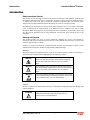
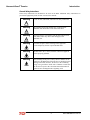
HarmonicGuard® Series Drive-Applied Harmonic Filter Installation, Operation, and Maintenance Manual TCI, LLC W132 N10611 Grant Drive Germantown, Wisconsin 53022 Phone: 414-357-4480 Fax: 414-357-4484 Helpline: 800-TCI-8282 Web Site: http://www.transcoil.com © 2014 TCI, LLC All rights reserved No part of this publication may be reproduced, stored in a retrieval system, or transmitted in any form or by any means, mechanical, electronic, photocopying, recording, or otherwise, without the prior written permission of TCI, LLC. The information in this manual is subject to change without notice. Every precaution has been taken in the preparation of this manual. TCI, LLC assumes no responsibility for errors or omissions. Neither is any liability assumed for damages resulting from the use of the information contained in this publication. Performance Guarantee Select & install the appropriate HarmonicGuard® Passive Harmonic Filter in a variable torque, variable frequency AC drive application, within our published technical specifications & we guarantee that the input current distortion will be less than or equal to 5% THID for standard HGP Series filters at full load, and less than 8% at 30% load. If a properly sized & installed filter fails to meet its specified THID level, TCI will provide material for necessary modifications or replacement filter at no charge. HG filters can also provide similar performance in other drive applications such as constant torque, DC drives & other phase controlled rectifiers, but actual THID levels can vary by load and/or speed & therefore cannot be guaranteed. Consult factory for assistance when applying HGP filters on these types of equipment. MINIMUM SYSTEM REQUIREMENTS: The guaranteed performance levels of this filter will be achieved when the following system conditions are met: Frequency: 60Hz ± 0.75Hz System Voltage: Nominal System Voltage (line to line) ±10% Balanced Line Voltage: Within 0.5% Background Voltage Distortion: < 0.5% THVD The input VFD current waveform shall be consistent with that of a VFD with 3% AC line reactance at full load. NOTE: The presence of background voltage distortion will cause motors & other linear loads to draw harmonic currents. Additional harmonic currents may flow into the HGP filter if there is harmonic voltage distortion already on the system. If higher levels of harmonic voltage distortion (2%-5%) are present, please use the high background distortion version of the HGP filter. Revision Description Date A Release 10/16/13 B Added Fuse Monitor Option 02/03/14 C Added Heater & Vibration Pad Options 09/10/14 D Added 600V Option Changed P/N to 28557-1 11/24/14 Table of Contents Introduction .............................................................................................................................. 1 Receiving Inspection and Storage .............................................................................. 3 Pre-installation Planning ............................................................................................. 4 Installation Guidelines ................................................................................................. 5 HGP Filter Operation .................................................................................................. 6 Installation ................................................................................................................................ 7 Maintenance and Service ........................................................................................... 7 Product Description .............................................................................................................. 11 Standard Option (S) ............................................................................................................... 15 Product Description ................................................................................................... 15 Contactor Option (C) ............................................................................................................. 16 Product Description ................................................................................................... 16 Fuse Monitor with Contactor Option (F).............................................................................. 17 Product Description ................................................................................................... 17 Fuse Monitor without Contactor Option (G) ....................................................................... 18 Product Description ................................................................................................... 18 Filter and Fuse Monitor Operation ....................................................................................... 19 CP Kit Enclosure (8) with Option (0) .................................................................................... 22 Product Description ................................................................................................... 22 KP Kit Enclosure (9) with Option (0) .................................................................................... 23 Product Description ................................................................................................... 23 Line Reactor Installation ........................................................................................... 24 Typical Voltage Distortion Option (0) .................................................................................. 26 High Voltage Distortion Option (1) ....................................................................................... 27 Heater Option (H) ................................................................................................................... 28 Vibration Pad Option (V) ....................................................................................................... 29 HarmonicGuard® Passive Introduction Introduction Safety Instructions Overview This section provides the safety instructions which must be followed when installing, operating, and ® servicing the HarmonicGuard Passive (HGP) filter. If neglected, physical injury or death may follow, or damage may occur to the filter or equipment connected to the HGP filter. The material in this chapter must be read and understood before attempting any work on, or with, the product. The HGP filter is intended to be connected to the input terminals of one or more VFDs. Three-phase power is connected to the input terminals of the HGP and power is supplied to the VFD or VFDs through the HGP. The instructions, and particularly the safety instructions, for the VFDs, motors, and any other related equipment must be read, understood, and followed when working on any of the equipment. Warnings and Cautions This manual provides two types of safety instructions. Warnings are used to call attention to instructions that describe steps that must be taken to avoid conditions that can lead to a serious fault condition, physical injury, or death. Cautions are used to call attention to instructions that describe steps that must be taken to avoid conditions that can lead to a malfunction and possible equipment damage. Warnings Readers are informed of situations that can result in serious physical injury and/or serious damage to equipment with warning statements highlighted by the following symbols: Warning Dangerous Voltage Warning: warns of situations where high voltage can cause physical injury and/or damage equipment. The text next to this symbol describes ways to avoid the danger. Warning General Warning: warns of situations that can cause physical injury and/or damage equipment by means other than electrical. The text next to this symbol describes ways to avoid the danger. ! Warning Electrostatic Discharge Warning: warns of situations in which an electrostatic discharge can damage equipment. The text next to this symbol describes ways to avoid the danger. Cautions Readers are informed of situations that can lead to a malfunction and possible equipment damage with caution statements: Caution ! General Caution: identifies situations that can lead to a malfunction and possible equipment damage. The text describes ways to avoid the situation. HGP IOM Manual - Rev. D 1 HarmonicGuard® Passive Introduction General Safety Instructions These safety instructions are intended for all work on the HGP. Additional safety instructions are provided at appropriate points on other sections of this manual. Warning Be sure to read, understand, and follow all safety instructions. ! Warning Only qualified electricians should carry out all electrical installation and maintenance work on the HGP filter. ! Warning ! All wiring must be in accordance with the National Electrical Code (NEC) and/or any other codes that apply to the installation site. Warning Disconnect all power before working on the equipment. Do not attempt any work on a powered HGP filter. Warning The HGP filter, drive, motor, and other connected equipment must be properly grounded. Warning After switching off the power, always allow 5 minutes for the capacitors in the HGP filter and in the drive to discharge before working on the HGP, the drive, the motor, or the connecting wiring. It is a good idea to check with a voltmeter to make sure that all sources of power have been disconnected and that all capacitors have discharged before beginning work. 2 HGP IOM Manual - Rev. D HarmonicGuard® Passive Introduction Receiving Inspection and Storage ® Thank you for selecting the HarmonicGuard Passive (HGP) filter. TCI has produced this filter for use in many variable frequency drive (VFD) applications that require input power line harmonic current reduction. This manual describes how to install, operate and maintain the HGP filter. Receiving Inspection The HGP filter has been thoroughly inspected and functionally tested at the factory and carefully packaged for shipment. When you receive the unit, you should immediately inspect the shipping container and report any damage to the carrier that delivered the unit. Verify that the part number of the unit you received is the same as the part number listed on your purchase order. TCI Limited Warranty Policy TCI, LLC (“TCI”) warrants to the original purchaser only that its products will be free from defects in materials and workmanship under normal use and service for a period originating on the date of shipment from TCI and expiring at the end of the period described below: Product Family KLR, KDR KLC, KLCUL, KMG, V1k HGP, KH, 3H, KRF KCAP, KTR, KMP All Other Products Warranty Period For the life of the drive with which they are installed. One (1) year of useful service, not to exceed 18 months from the date of shipment. Three (3) years from the date of shipment. Five (5) years from the date of shipment. One (1) year of useful service, not to exceed 18 months from the date of shipment. The foregoing limited warranty is TCI’s sole warranty with respect to its products and TCI makes no other warranty, representation, or promise as to the quality or performance of TCI’s products. THIS EXPRESS LIMITED WARRANTY IS GIVEN IN LIEU OF AND EXCLUDES ANY AND ALL EXPRESS OR IMPLIED WARRANTIES INCLUDING, WITHOUT LIMITATION, ANY IMPLIED WARRANTY OF MERCHANTABILITY OR FITNESS FOR A PARTICULAR PURPOSE. This warranty shall not apply if the product was: a) Altered or repaired by anyone other than TCI; b) Applied or used for situations other than those originally specified; or c) Subjected to negligence, accident, or damage by circumstances beyond TCI’s control, including but not limited to, improper storage, installation, operation, or maintenance. If, within the warranty period, any product shall be found in TCI’s reasonable judgment to be defective, TCI’s liability and the Buyer’s exclusive remedy under this warranty is expressly limited, at TCI’s option, to (i) repair or replacement of that product, or (ii) return of the product and refund of the purchase price. Such remedy shall be Buyer’s sole and exclusive remedy. TCI SHALL NOT, IN ANY EVENT, BE LIABLE FOR INCIDENTAL DAMAGES OR FOR CONSEQUENTIAL DAMAGES INCLUDING, BUT NOT LIMITED TO, LOSS OF INCOME, LOSS OF TIME, LOST SALES, INJURY TO PERSONAL PROPERTY, LIABILITY BUYER INCURS WITH RESPECT TO ANY OTHER PERSON, LOSS OF USE OF THE PRODUCT OR FOR ANY OTHER TYPE OR FORM OF CONSEQUENTIAL DAMAGE OR ECONOMIC LOSS. The foregoing warranties do not cover reimbursement for removal, transportation, reinstallation, or any other expenses that may be incurred in connection with the repair or replacement of the TCI product. The employees and sales agents of TCI are not authorized to make additional warranties about TCI’s products. TCI’s employees and sales agent’s oral statements do not constitute warranties; these shall not be relied upon by the Buyer, and are not part of any contract for sale. All warranties of TCI embodied in this writing and no other warranties are given beyond those set forth herein. TCI will not accept the return of any product without its prior written approval. Please consult TCI Customer Service for instructions on the Return Authorization Procedure. Storage Instructions If the HGP filter is to be stored before use, be sure that it is stored in a location that conforms to ® published storage humidity and temperature specifications stated in the HarmonicGuard Passive Filter Technical Specifications. Store the unit in its original packaging. HGP IOM Manual - Rev. D 3 HarmonicGuard® Passive Introduction Pre-installation Planning Verify the Application HGP Ratings Make sure that the HGP filter is correct for the application. The voltage ratings of the filter must match the input voltage rating of the connected drive. The horsepower and current ratings of the filter must be appropriate for the connected load. Select a Suitable Location Environment Locating the HGP in a suitable environment will help ensure proper performance and a normal operating life. Refer to the environmental specifications listed in Table 2 and/or noted on the drawings furnished with the unit. Warning ! Unless specifically labeled as approved for such use, this equipment is not suitable for use in an explosive atmosphere or in a "Hazardous (Classified) Location" as defined in article 500 of the National Electrical code. The unit must be installed in an area where it will not be exposed to: Direct sunlight Rain or dripping liquids (unless filter is in a Type 3R enclosure) Corrosive liquids or gasses Explosive or combustible gases or dust Excessive airborne dirt and dust Excessive vibration Working Space Provide sufficient access and working space around the unit to permit ready and safe installation, operation and maintenance. Make sure that the installation conforms to all working space and clearance requirements of the National Electrical Code (NEC) and/or any other applicable codes. Provide sufficient unobstructed space to allow cooling air to flow through the unit. Mounting an Open Panel Unit If you are mounting an open panel unit in your own enclosure, you must provide an enclosure that is adequately sized and ventilated sufficiently to prevent overheating. The rating and dimension tables for open panel units list the watts of heat loss dissipated by the HGP filter. The maximum temperature of the air around the HGP filter capacitors, line reactor, and tuning reactor should not exceed 50°C (122°F). Power Wiring When selecting a mounting location for the HGP filter, plan for the routing of the power wiring. Route the conduit and wiring from the power source to the filter and then to the VFD. The HGP is provided with internal fuses. 4 HGP IOM Manual - Rev. D HarmonicGuard® Passive Introduction Installation Guidelines Mounting The HGP must be mounted vertically on a smooth, solid surface, free from heat, dampness, and condensation. Wiring Cable Entry Locations The enclosed HGP filters are not provided with enclosure wiring knockouts. A location can be selected at the time of installation. Typical or recommended cable entry locations are shown in the drawings section of this manual. Field Wiring Connection Terminals Compression type terminals are provided for all field wiring connections. The wire size capacity ranges and tightening torques for all field wiring connections are listed in the drawings and other information shipped with the unit. Grounding The HGP panel equipment-grounding lug must be connected to the ground of the wiring system. The equipment-grounding connection must conform to the requirements of the National Electric Code (NEC) and/or any other codes that apply to the installation site. The ground connection must be made using a wire conductor. Metallic conduit is not a suitable grounding conductor. The integrity of all ground connections should be periodically checked. Power Wiring Caution ! Use copper wire that is appropriate for the voltage and current rating of the equipment. The wire selection must conform to the requirements of the National Electrical Code and/or other applicable electrical codes. For units rated less than 100 amps, use wire with an insulation temperature rating of 60°C or higher. For units rated 100 amps or more, use wire with an insulation temperature rating of 75°C or higher. Connect three-phase power of the appropriate voltage and current capacity to the circuit protective device to the HGP input power terminals. Note: in large units, the input power conductors are connected directly to the input terminals on the line reactors. Connect the output terminals of the HGP to the input power terminals of the VFD. Note: in large units, the output power conductors are connected directly to the output terminals on the line reactors. Refer to the VFD installation instructions for additional information. HGP IOM Manual - Rev. D 5 HarmonicGuard® Passive Introduction HGP Filter Operation Caution Thoroughly check the installation before applying power and operating the equipment for the first time. ! Before Applying Power for the First Time Inspect the installation to make sure that all equipment has been completely and correctly installed in accordance with the Installation Guidelines section of this manual. Check to see that the cooling fan(s) are operating in units so equipped. Check to make sure power connections are torqued to recommended torque value. Operation Since the HGP is a passive filter, it is always operating whenever the drive is operating. 6 HGP IOM Manual - Rev. D HarmonicGuard® Passive Installation Installation Intended Audience This manual is intended for use by all personnel responsible for the installation, operation and maintenance of the HGP filters. Such personnel are expected to have knowledge of electrical wiring practices, electronic components and electrical schematic symbols. Additional Information Caution ! This manual provides general information describing your HGP filter. Be sure to carefully review the more specific information that is provided by the drawings shipped with the unit. Information provided by the drawings takes precedence over the information provided in this manual. The ratings, dimensions and weights given in this manual are approximate and should not be used for any purpose requiring exact data. Contact the factory in situations where certified data is required. All data is subject to change without notice. Installation Checklist The following are the key points to be followed for a successful installation. These points are explained in detail in the following sections of this manual. Make sure that the installation location will not be exposed to direct sunlight, corrosive or combustible airborne contaminants, excessive dirt or liquids. Select a mounting area that will allow adequate cooling air and maintenance access. Make sure that all wiring conforms to the requirements of the National Electric Code (NEC) and/or other applicable electrical codes. Connect the HGP equipment-grounding lug to the system ground of the premises wiring system. Use a properly sized grounding conductor. Connect three-phase power to the input terminals of the HGP, L1, L2 & L3. Connect the output power terminals, of the HGP, T1, T2 & T3, to the input power terminals of the VFD. Maintenance and Service HGP Filter Reliability and Service Life The HGP has been designed to provide a service life that equals or exceeds the life of the VFD. It has been thoroughly tested at the factory to assure that it will perform reliably from the time it is put into service. It is recommended that the following maintenance is performed once a year to ensure that the HGP filter will always operate reliably and provide the expected service life. Periodic Maintenance Warning Only qualified electricians should carry out all electrical installation and maintenance work on the HGP filter. Disconnect all sources of power to the drive and HGP before working on the equipment. Do not attempt any work on a powered HGP. HGP IOM Manual - Rev. D 7 HarmonicGuard® Passive Installation Check to see that the installation environment remains free from exposure to excessive dirt and contaminants. Refer to the Pre-installation Planning section of this manual. Check to make sure that the enclosure ventilation openings are clean and unobstructed. Clean the air filter in units that have filtered air inlets. Clean as often as necessary to prevent dirt buildup from impeding air flow. Check the operation of the cooling fan. Inspect the interior of the enclosure for signs of overheated components. Clean the interior of the enclosure whenever excess dirt has accumulated. Torque all power wire connections, loose connections can overheat and damage the filter. All electrical connections must be re-torqued annually. Troubleshooting Warning Only qualified electricians should carry out all electrical installation and maintenance work on the HGP filter. Disconnect all sources of power to the drive and HGP before working on the equipment. Do not attempt any work on a powered HGP filter. The harmonic filter contains high voltages and capacitors. Wait at least five minutes after disconnecting power from the filter before you attempt to service the harmonic filter. Check for zero voltage between all terminals on the capacitors. Also, check for zero voltage between all phases of the line side of the fuses, Fu1(a)–Fu2(a)–Fu3(a), and all input terminals L1, L2 and L3 of the line reactor (KDR). All setup, maintenance, and troubleshooting must be done by a qualified electrician. Failure to follow standard safety procedures may result in death or serious injury. Note: when disconnecting wires from components and terminations, mark the wires to correspond to their component and terminal connection. Replacement Parts If replacement parts are needed, please contact your TCI representative. To ensure that the HGP filter continues to perform to its original specifications, replacement parts should conform to TCI specifications. 8 HGP IOM Manual - Rev. D HarmonicGuard® Passive Installation Fuse Specifications Always refer to the drawings and other information shipped with your unit. 100 kA SCCR Fusing Requirements Below is a table of line fusing requirements that must be supplied to comply with the 100kA SCCR rating. P r o v i Voltage Size Required Action(s) 480V ≤ 40 HP Use appropriately rated Class J, T, CC, or L fuse less than or equal to 60 A 480V ≥ 50 HP Use Class J, T, CC, or L fuses appropriate for rating of conductor used to connect to source 600V ≤ 30 HP Use appropriately rated Class J, T, CC, or L fuse less than or equal to 60 A 600V ≥ 40HP Use Class J, T, CC, or L fuses appropriate for rating of conductor used to connect to source Provisional 480V Fuse Table The provisional 480V fuse table below specifies the max branch circuit and max line fuse ratings for the 480V HGP units. If a 100KA rating is desired customers must provide line fusing to complete the SCCR 100KA rating Table 1 – Provisional Fuse Table for HGP 480 Volt Models HGP Rating (HP) kVar 5 7.5 10 15 20 25 30 40 50 60 75 100 125 150 200 250 300 350 400 450 500 600 700 800 900 1.3 3 3 5 6 8 10 15 15 20 25 30 40 45 60 75 90 105 120 135 150 180 210 240 270 Max Branch Circuit Fuse Max Line Fusing (J or T) (J, T or L) 20 20 20 20 20 20 30 30 30 50 50 60 80 100 125 150 175 200 225 250 300 350 200/200 (Parallel Branches) 225/225 (Parallel Branches) 250/250 (Parallel Branches) 30 30 30 30 60 60 60 60 80 100 125 150 200 225 300 375 450 500 600 600 800 900 1000 1200 1350 NOTE: Customers must provide line fusing to complete SCCR 100KA rating. HGP IOM Manual - Rev. D 9 HarmonicGuard® Passive Installation Provisional 600V CP and KP Kit Fuse Table The fuse tables provided below list the branch circuit current and a recommended fuse rating that will offer a reasonable level of protection of the branch circuit. The fuses specified in the provisional fuse table are dependent upon any other components used in conjunction with the HGP kit such as a customer supplied contactor or power distribution block. The intent of the provisional fuse table is to provide the minimum sizing option for the wiring that can be used. Refer to the fuse requirements for the selected contactor and power distribution block provided by the contactor and power distribution block manufacturer for specific fusing required for your application. Table 2 – Provisional Fuse Specifications for HGP 600 Volt Models HP kVar Branch Current Amps Branch Circuit Fuse 15 5 6.8 10 30 10 13.7 20 40 15 20.5 25 50 15 20.5 25 60 20 27.4 35 75 25 34.2 40 100 30 41.0 50 125 40 54.7 70 150 45 61.6 80 200 60 82.1 100 250 75 103.0 125 300 90 123 150 350 105 144 175 400 120 164 200 450 135 185 225 500 150 205 250 600 180 246 300 700 210 287 300 800 240 328 350 900 270 369 400 Factory Contacts and Tech Support For technical support, contact your local TCI distributor or sales representative. You can contact TCI directly at 800-TCI-8282. Select "Customer Service" or "Tech Support" and have your HGP filter nameplate information available. 10 HGP IOM Manual - Rev. D HarmonicGuard® Passive Product Description Product Description HGP Drive-Applied Filter The HGP is a drive-applied harmonic filter designed and developed by TCI to reduce the harmonic currents drawn from the power source by VFDs. It is suitable for use with 3-phase diode bridge rectifier loads such as PWM AC drives. SCR or thyristor loads such as DC drives would require a different filter configuration outside the scope of this product offering. Please contact TCI Technical Support for additional information. The HGP is a passive filter connected in series with the input terminals of a VFD or several VFDs that operate as a group. It is designed to provide a low impedance path for the major harmonic currents demanded by the drive. The filter is a stand-alone device that can be furnished in its own enclosure and mounted adjacent to the drive. It is also available on an open panel for mounting within an enclosure with the drive or other equipment. The HGP filters consist minimally of the following features and components: A KDR tuned series reactor to prevent system interaction and improve filter performance An L-C-L filter circuit with: A TCI 3-phase tuning reactor specifically designed for the HGP filter High-endurance, harmonic-rated capacitors Multiple tuned circuits on 700 HP to 900 HP Bleeder resistors to ensure safe capacitor discharge upon filter shutdown Cooling fans (on select models) to ensure adequate cooling and safe operating temperatures Compression terminals for ease and integrity of all power and control wiring Fuses, sized to protect the capacitor wiring Nameplate Data The following information is marked on the nameplate: Part number: encoding is explained on the following page FLA: the rated continuous operating current (RMS amps) System Voltage: the rated 3-phase line voltage (RMS volts) Hz: the rated frequency (60 Hz) Phase: 3 – The HGP filter is designed for use only with 3-phase power. Drawing #: outline and mounting dimension drawing number Schematic #: schematic diagram drawing number Manufacturing #: for TCI internal use Enclosure Type: UL designation or "Open" panel construction HGP IOM Manual - Rev. D 11 HarmonicGuard® Passive Product Description Part Number Encoding Figure 1 identifies the significance of each character in the HGP part number. The example part number, HGP0150AW1S0000 designates an HGP filter that is rated 150 HP, 480 volts, 60 Hz. It includes a line reactor, tuning reactor, and capacitors in a UL Type 1 enclosure. It is designed for use with a 150 HP drive. HGP 0 1 5 0 A W 1 S 0 0 0 0 Series: Horse Power: Voltage Rating: A - 480 V C - 600 V Frequency: W - 60 Hz Enclosure: 0 - Open 1 - Type 1 3 - Type 3R 8 - CP Kits 9 - KP Kits Option: S - Standard C - Contactor F - Fuse Monitor with Contactor G - Fuse Monitor without Contactor Option: 0 - Standard Option: 0 - Standard Option: 0 - Typical Voltage Distortion 1 - High Voltage Distortion Option: 0 - Standard H - Heater* V - Vibration Pads * Heater Only Available on Type 3R Enclosures Figure 1 – HGP Part Number Encoding 12 HGP IOM Manual - Rev. D HarmonicGuard® Passive Product Description Product Technical Specifications Table 2 lists the major technical specifications for the HGP Filter. Table 3 – HGP Technical Specifications Voltage ratings 480V, 3 phase, 60 Hz / 600V, 3 phase, 60 Hz kVar ratings 1.3 to 270 kVar depending on voltage. Load types 3-phase diode bridge rectifier loads such as PWM AC drives Load power range 5 -900 HP The included series reactors can tolerate 200% of rated current for at Current ratings least 3 minutes. SCCR (short circuit current Standard rating is 100kA. rating) Maximum elevation 3,000 feet (1,000 meters) as standard. 50°C (122°F) – Open Panel; 40°C (104°F) – Enclosed Panel. Maximum ambient operating Product must be equipped with special cooling provisions for temperature operation above this temperature. Maximum ambient storage 60°C (140°F) temperature Maximum humidity, 95%, non-condensing. operating or storage UL Type 1 enclosure Enclosure options UL Type 3R enclosure Open Panel Agency approvals or certifications Insertion Impedance Fusing and protection: UL and cUL Listed to UL508A +/- 10% at full load current All units have internal fuse protection for the harmonic filter circuit. Performance Guarantee To meet the requirements for the Performance Guarantee the minimum system conditions must conform to the following: No more than 1.5% Source inductance The input VFD current waveform shall be consistent with that of a VFD with 3% AC line reactance at full load HGP IOM Manual - Rev. D 13 HarmonicGuard® Passive Product Description Table 4 – 480V HGP Watts loss HP 5 7.5 10 15 20 25 30 40 Heat Loss (watts) 140 150 175 250 275 250 300 500 HP 60 75 100 125 150 200 250 300 Heat Loss (watts) 675 650 750 1000 1200 1600 1800 2100 50 550 350 2200 HP 125 150 200 250 300 350 400 Heat Loss (watts) 1040 1160 1370 1520 1630 1690 1710 HP 400 450 500 600 700 800 900 Heat Loss (watts) 2600 2800 3100 2700 2900 3000 3300 HP 450 500 600 700 800 900 800 Heat Loss (watts) 1710 1710 1770 2030 2420 2420 2420 Table 5 – 600V HGP Watts loss HP 15 30 40 50 60 75 100 Heat Loss (watts) 190 340 430 520 600 720 890 14 HGP IOM Manual - Rev. D HarmonicGuard® Passive Options Standard Option (S) The Standard Option includes high quality harmonic-grade capacitors and line reactors. This filter will meet the majority of application requirements found today. This cost effective product is available as an open panel version, in a UL Type 1 enclosure, or in an UL Type 3R enclosure. The open panel is perfect for inclusion in a MCC section or easy installation into industry standard enclosures. The UL Type 1 enclosed units maintain the same vertical profile as the open panel design. This design is perfect for applications where floor space is at a premium. The UL Type 3R enclosure protects the filter from harsh conditions. Product Description HGP S Option Filter The HGP harmonic filter is a drive-applied harmonic filter designed and developed by TCI to reduce the harmonic currents drawn from the power source by VFDs. The HGP harmonic filter is for 480 volt systems (60 Hz). It is suitable for use with 3-phase diode bridge rectifier loads such as PWM AC VFDs. The HGP harmonic filter is a passive filter connected in series with the input terminals of a VFD or several VFDs that operate as a group. It is designed to provide a low impedance path for the major harmonic currents demanded by the VFD. The filter is a stand-alone device that can be furnished in its own enclosure and mounted adjacent to the VFD. It is also available on an open panel for mounting within an enclosure with the VFD or other equipment. The HGP Standard Option consists of the following standard features and components: A KDR tuned series reactor. A TCI 3-phase tuning reactor specifically designed for the HGP filter. High-endurance, harmonic-rated capacitors. Bleeder resistors to ensure safe capacitor discharge upon filter shutdown, located on capacitors. Cooling fans (on select models) to ensure adequate cooling and safe operating temperatures. Control Power transformer on enclosed units requiring auxiliary cooling fans. Compression terminals for ease and integrity of all power and control wiring. Fuses HGP IOM Manual Rev. - D 15 HarmonicGuard® Passive Options Contactor Option (C) The Contactor Option includes a contactor, control power transformer and connection terminals in the filter circuit which allows the VFD user to control the insertion of this circuit through the use of a relay contact in the VFD. It is recommended that the VFD contact be programmed to open the contactor below 33% motor power. For variable torque (fan) loads this will be approximately below 70% speed, so the at-speed contact may be used. This reduces the possibility of leading power factor interacting with other devices on the power system. Contactor logic should also maintain the contactor closed in cases where the VFD is bypassed and the filter is not bypassed. Product Description HGP C Option Filter The HGP harmonic filter is a drive-applied harmonic filter designed and developed by TCI to reduce the harmonic currents drawn from the power source by VFDs. The HGP harmonic filter is for 480 volt systems (60 Hz). It is suitable for use with 3-phase diode bridge rectifier loads such as PWM AC VFDs. The HGP harmonic filter is a passive filter connected in series with the input terminals of a VFD or several VFDs that operate as a group. It is designed to provide a low impedance path for the major harmonic currents demanded by the VFD. The filter is a stand-alone device that can be furnished in its own enclosure and mounted adjacent to the VFD. It is also available on an open panel for mounting within an enclosure with the VFD or other equipment. The HGP Contactor Option consists of the following standard features and components: A KDR tuned series reactor. A TCI 3-phase tuning reactor specifically designed for the HGP filter. High-endurance, harmonic-rated capacitors. Bleeder resistors to ensure safe capacitor discharge upon filter shutdown, located on capacitors. Filter enable/disable contactor with protection and drive interlock provisions. Cooling fans (on select models) to ensure adequate cooling and safe operating temperatures. Control power transformer Compression terminals for ease and integrity of all power and control wiring. Fuses Contactor 16 HGP IOM Manual - Rev. D HarmonicGuard® Passive Options Fuse Monitor with Contactor Option (F) The Fuse Monitor with Contactor Option includes a voltage monitor module and relay that can be connected to a VFD or other device. The fuse monitor will indicate a fuse failure and communicate this condition through the relay to a connected device. This option includes a contactor, control power transformer, and connection terminals in the filter circuit which allows the VFD user to control the insertion of this circuit through the use of a relay contact in the VFD. It is recommended that the drive contact be programmed to open the contactor below 33% motor power. For variable torque (fan) loads this will be approximately below 70% speed, so the at-speed contact may be used. This reduces the possibility of leading power factor interacting with other devices on the power system. Contactor logic should also maintain the contactor closed in cases where the VFD is bypassed and the filter is not bypassed. Product Description HGP F Option Filter The HGP harmonic filter is a drive-applied harmonic filter designed and developed by TCI to reduce the harmonic currents drawn from the power source by VFDs. The HGP harmonic filter is for 480 volt systems (60 Hz). It is suitable for use with 3-phase diode bridge rectifier loads such as PWM AC drives. The HGP harmonic filter is a passive filter connected in series with the input terminals of a VFD or several VFDs that operate as a group. It is designed to provide a low impedance path for the major harmonic currents demanded by the VFD. The filter is a stand-alone device that can be furnished in its own enclosure and mounted adjacent to the VFD. It is also available on an open panel for mounting within an enclosure with the VFD or other equipment. The HGP F Option consists of the following standard features and components: A KDR tuned series reactor A TCI 3-phase tuning reactor specifically designed for the HGP filter High-endurance, harmonic-rated capacitors Bleeder resistors to ensure safe capacitor discharge upon filter shutdown, located on capacitors Filter enable/disable contactor with protection and drive interlock provisions. Cooling fans (on select models) to ensure adequate cooling and safe operating temperatures Control power transformer Compression terminals for ease and integrity of all power and control wiring Fuses Contactor Voltage monitor module to report status of fuses to control HGP IOM Manual - Rev. D 17 HarmonicGuard® Passive Options Fuse Monitor without Contactor Option (G) The Fuse Monitor without Contactor Option includes a voltage monitor module and relay that can be connected to a VFD or other device. The fuse monitor will indicate a fuse failure and communicate this condition through the relay to a connected device. Product Description HGP G Option Filter The HGP harmonic filter is a drive-applied harmonic filter designed and developed by TCI to reduce the harmonic currents drawn from the power source by VFDs. The HGP harmonic filter is for 480 volt systems (60 Hz). It is suitable for use with 3-phase diode bridge rectifier loads such as PWM AC VFDs. The HGP harmonic filter is a passive filter connected in series with the input terminals of a VFD or several VFDs that operate as a group. It is designed to provide a low impedance path for the major harmonic currents demanded by the VFD. The filter is a stand-alone device that can be furnished in its own enclosure and mounted adjacent to the VFD. It is also available on an open panel for mounting within an enclosure with the VFD or other equipment. The HGP G Option consists of the following standard features and components: A KDR tuned series reactor A TCI 3-phase tuning reactor specifically designed for the HGP filter High-endurance, harmonic-rated capacitors Bleeder resistors to ensure safe capacitor discharge upon filter shutdown, located on capacitors Cooling fans (on select models) to ensure adequate cooling and safe operating temperatures Control Power transformer on enclosed units requiring auxiliary cooling fans Compression terminals for ease and integrity of all power and control wiring Fuses Voltage monitor module to report status of fuses to control 18 HGP IOM Manual - Rev. D HarmonicGuard® Passive Options Filter and Fuse Monitor Operation HGP Filter Overview The Harmonic Guard Passive (HGP) Filter provides a low impedance path for the major harmonic currents demanded by Variable Frequency Drives (VFDs). This greatly reduces the amount of harmonic currents flowing through the electrical power distribution system, bringing those harmonic currents in line with the IEEE-519 standard for harmonic distortion mandated by an increasing number of utilities. The HGP Filter includes branch fuses on the harmonic trap circuit capacitors. These fuses are included in the design to prevent damage to the capacitors in the event of excessive harmonic trap current if the filter is misapplied. HGP Fuse Monitor Overview The HGP Fuse Monitor Option is used in conjunction with the HGP filter to monitor the status of the HGP branch circuit capacitor fuses and optional contactor. If a blown fuse condition is detected the HGP Fuse Monitor Option will energize a SPDT relay contact. Additionally, the Fuse Monitor Option is used to indicate the state of the optional contactor that allows users to remove the capacitors from the circuit, eliminating the possibility of leading power factor. Finally, the Fuse Monitor Option provides the additional benefit of detecting drive input voltage phase reversal and loss of phase. The HGP Fuse Monitor can be connected to a programmable digital input available on most modern VFDs and/or Programmable Logic Controllers (PLCs). Once the status of the HGP Fuse Monitor is routed to a programmable digital input the status of the Fuse Monitor can be relayed on the VFDs or PLCs integrated communications field bus or Industrial Ethernet network interface. The Fuse Monitor is available on 480V HGP filters and 600V HGP KP and CP kit options. Figure 2 – HGP Filter and Fuse Monitor Option Block Diagram HGP IOM Manual - Rev. D 19 HarmonicGuard® Passive Options Fuse Monitor Operation and Relay Specifications The fuse monitor relay contact is a single pole, double throw (SPDT) dry type contact. Terminal Block connection TBa-7 is the common connection, TBa-6 is the Normally Closed (NC) connection, and TBa-8 is the Normally Open (NO) Connection. Table 2 – Fuse Monitor Operation Modes and Output Table Operating State No Input Line Voltage Input Line Voltage has Missing Phase Input Line Voltage has Phase Reversal HGP Filter has Blown Trap Fuse N.O. Relay Contact (TBa-7 TBa-8) Open Monitor Status LED Not Present X* N.C. Relay Contact (TBa-6 TBa-7) Closed Phase Loss X* Closed Open Blinking Red Phase Reversal X* Closed Open Solid Red Closed Open Blinking Red or Off Closed Open Blinking Red or Off Closed Open Off Open Closed Solid Green Input Voltage Nominal HGP Fuse Monitor has Blown Fuse Nominal HGP Filter Contactor is Open Nominal Nominal Nominal HGP Filter Blown Trap Fuse Blown Monitor Fuse Contactor Open Contactor Closed Off *X = don’t care condition ** During unit power on / restart monitor LED will be blinking green Table 3 – HGP Filter Fuse Monitor Relay Contact Specifications Relay Contact Location Normally Open Contact (TBa-7 TBa-8) Normally Closed Contact (TBa-6 TBa-7) Contact Rating 10A @ 277V AC/ 7A @ 30VDC 1 HP @ 250V AC, 1/2HP @125V AC, C300 Pilot Duty 10A @ 277V AC/ 7A @ 30VDC 1 HP @ 250V AC, 1/2HP @125V AC, C300 Pilot Duty 20 HGP IOM Manual - Rev. D HarmonicGuard® Passive Options Figure 3 – HGP Filter Fuse Monitor Typical Connection Circuit Diagram HGP IOM Manual - Rev. D 21 HarmonicGuard® Passive Options CP Kit Enclosure (8) with Option (0) The HGP CP Kit Option is a harmonic filter component package designed and developed by TCI to allow qualified customers to build harmonic filters to reduce the harmonic currents drawn from the power source by VFDs. The HGP CP Option is available for 480 volt and 600 volt systems (60 Hz). When properly designed, assembled, and installed, the completed product is intended to be suitable for use with 3-phase diode bridge rectifier loads such as PWM AC VFDs. SCR or thyristor loads such as DC drives would require a different filter configuration outside the scope of this product offering. Please contact TCI Technical Support for additional information. Product Description HGP CP Kit Option Filter The HGP CP Kit Option is a package of the primary passive filter components needed to build and install a harmonic filter on a VFD or VFD system. The filter components are tuned to provide a low impedance path for the major harmonic currents demanded by the VFD when following the schematic connections used by TCI in the HGP filter. The HGP CP Option filter component package consists of the following components: A KDR tuned series reactor A TCI 3-phase tuning reactor specifically designed for the HGP filter High-endurance, harmonic-rated capacitors Bleeder resistors to ensure safe capacitor discharge upon filter shutdown, located on capacitors Fasten terminals for wiring single-phase capacitors (select models) 22 HGP IOM Manual - Rev. D HarmonicGuard® Passive Options KP Kit Enclosure (9) with Option (0) The HGP “KP” Option is a harmonic filter component package designed and developed by TCI to allow qualified customers to build harmonic filters to reduce the harmonic currents drawn from the power source by variable speed drives. The HGP “KP” Option is available for 200/208, 230/240, 460/480 volt, 575/600 volt systems (60 Hz) and 380 – 415 volt systems (50 Hz). When properly designed, assembled, and installed, the completed product is intended to be suitable for use with 3 phase diode bridge rectifier loads such as PWM AC drives. I98SCR or thyristor loads such as DC drives would require a different filter configuration outside the scope of this product offering. Please contact TCI Technical Support for additional information. Product Description HGP KP Kit Option Filter The HGP KP Kit Option is a package of the primary passive filter components needed to build and install a harmonic filter on a VFD or VFD system. The filter components are tuned to provide a low impedance path for the major harmonic currents demanded by the VFD when following the schematic connections used by TCI in the HGP filter. The HGP “KP” Option filter component package consists of the following components: A KDR input series reactor A TCI 3-phase tuning reactor specifically designed for the HGP filter KPC panelized, high-endurance, harmonic-rated capacitors Bleeder resistors to ensure safe capacitor discharge upon filter shutdown, located on capacitors HGP IOM Manual - Rev. D 23 HarmonicGuard® Passive Options Line Reactor Installation Review all Pre-Installation and Installation instructions at the beginning of this manual. If you are assembling a CP unit in your own enclosure, you must provide an enclosure that is adequately sized and ventilated sufficiently to prevent overheating. The maximum temperature of the air around the HGP filter capacitors should not exceed 50°C (122°F). KDR Line Reactor Installation Instruction Recommendations and Considerations: When installing the KDR Line Reactors on the INPUT side of the VFD, please use the following guidelines when wiring the unit: The KDR Line Reactor is a 3-phase device and should be wired in series and positioned on the input side of the VFD. All Terminal Block connectors will be marked. A1, B1, and C1 are the input terminals where the 3 phases of incoming power are to be wired. The tap for the filter connection will be marked AT, BT, and CT. Output terminals will be marked A2, B2, and C2. Do not swap input and output terminals. Units with copper bus or ring lug terminals are not marked. Wiring from the output terminals should connect to the input of the VFD. Refer to NEC wiring practices for appropriate wire sizes for your application. TCI recommends that these reactors be wired and located as close to the front end of the VFD as possible to have the greatest success in both protecting the VFD as well as mitigating line harmonics. We recommend this be 10 feet of cable or less. Reactors generate a lot of heat in normal operations, and their surfaces get very hot. In standard 40°C ambient or less installations, a clearance of 3 inches on all sides of the reactors and its enclosure is recommended for assisting in heat dissipation. This is a general guideline for typical applications. If the reactor is being installed next to a heat sensitive instrument or control device, we recommend reviewing specific requirements or heat limitations. Line reactor heat loss information is available in the standard TCI product literature or on the web at www.transcoil.com. These reactors are designed to be floor-mounted, or wall-mounted. Large open-style devices should be panel mounted by incorporating a bracket that would act as a shelf to support the reactor and/or enclosure. When installing an open style device in an existing control cabinet, drive cabinet, motor control center, or other large enclosure, the reactor should be mounted in the lower half of the cabinet to prevent hot spots or pockets of heat. Locating the reactor in the lower half of the cabinet typically allows better thermal dissipation and heat convection. Reactors with ducts should be mounted vertically for proper cooling. Recommendations for CP Kit Usage to Achieve 100kA SCCR Panel design using a TCI HGP kit should be performed with appropriate engineering supervision so the design meets the requirements based on materials you utilize in the construction of your panel, the wiring practices your shop utilizes, and the actual ambient conditions the components will see in your application. Wire Sizing Appropriate wire sizing can be calculated using the information in the fuse specification table (See Table 6). Wires need to be sized based on current to be carried, wire insulation temperature rating, panel temperature rating, bundling of wires, and appropriate codes and standards. Wire size between the power source and the filter line reactor as well as the line reactor and the drive input are based rated filter line current. Wire size in the trap circuit is based on rated trap current. If the capacitor wiring is split into separate capacitor branches, the current each branch carries is proportional to the value of capacitance in each branch. 24 HGP IOM Manual - Rev. D HarmonicGuard® Passive Options Table 4 – Fuse Specifications for HGP 480 Volt Models HGP Rating (HP) kVar 5 7.5 10 15 20 25 30 40 50 60 75 100 125 150 200 250 300 350 400 450 500 600 700 800 900 1.3 3 3 5 6 8 10 15 15 20 25 30 40 45 60 75 90 105 120 135 150 180 210 240 270 Max Branch Circuit Fuse Max Line Fusing (J or T) (J, T or L) 20 20 20 20 20 20 30 30 30 50 50 60 80 100 125 150 175 200 225 250 300 350 200/200 (Parallel Branches) 225/225 (Parallel Branches) 250/250 (Parallel Branches) 30 30 30 30 60 60 60 60 80 100 125 150 200 225 300 375 450 500 600 600 800 900 1000 1200 1350 NOTE: Customers must provide line fusing to complete SCCR 100KA rating. Selection of Contactors As an option, you can include contactors to remove the trap circuit from the filter under no load or light load conditions. Review the impedance of the line reactor, this isolates the trap circuit capacitors from line transients, removing the need for special capacitor rated contactors in this application. Contactors in the trap circuit can be selected based on the rated trap circuit current using the UL general purpose rating of your intended contactors. Options TCI fuses the trap circuit to isolate the trap circuit in the case of component damage. Some failures could leave an unbalanced load on the trap, which can damage additional parts. A fuse in the trap circuit can be selected based on trap circuit rated current. SCCR Issues If you need an SCCR rating greater than the default values of components: For example 10 kA for terminal blocks or 5 kA for contactors, pay attention to component selection and circuit fusing. Contactors need to be protected by line or trap fusing based on their published SCCR ratings. For trap circuits less than or equal to 40 HP, the incoming line circuit protection of Class J or Class T rated less than or equal to 60 A will result in 10 kA being supplied to the panel, allowing any type of filter capacitors to be used. Larger filter kits are provided with dry capacitors, which are exempt from SCCR calculations. HGP IOM Manual - Rev. D 25 HarmonicGuard® Passive Options Typical Voltage Distortion Option (0) The Typical Voltage Distortion Option, intended for applications with levels of background voltage distortion less than 2%, is a configuration that enables the HGP filter to achieve lower levels of current harmonic distortion in applications with low background voltage distortion. This performance option is available in all of the package options. 26 HGP IOM Manual - Rev. D HarmonicGuard® Passive Options High Voltage Distortion Option (1) The High Voltage Distortion Option, intended for applications with levels of background voltage distortion of 2% or higher, is a configuration that enables the HGP filter to achieve lower levels of current harmonic distortion in applications with high background voltage distortion. This performance option is available in all of the package options. HGP IOM Manual – Rev. D 27 HarmonicGuard® Passive Options Heater Option (H) The Heater Option is intended for use in applications which require the environmental protection of a NEMA 3R enclosure. The heater is mounted to the interior of the enclosure and protects sensitive electronic equipment from the harmful effects of corrosion and condensation. The Heater option is available for all 3R enclosures. 28 HGP IOM Manual – Rev. D HarmonicGuard® Passive Options Vibration Pad Option (V) The Vibration Pad Option is intended for use in applications which require environmental noise protection. The resilient mounting material is placed between the reactor and the interior of the enclosure and dampens noise produced by the reactor. The Vibration Pad option is available for all enclosure types. HGP IOM Manual – Rev. D 29 TCI, LLC W132 N10611 Grant Drive Germantown, Wisconsin 53022 Phone: 414-357-4480 Fax: 414-357-4484 Helpline: 800-TCI-8282 Web Site: http://www.transcoil.com © 2014 TCI, LLC All rights reserved ©2014 TCI, LLC Printed in USA Publication No: 28557-1 Effective: 11/24/2014 Version: D