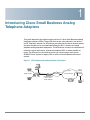
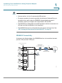
1
ADMINISTRATION
GUIDE
Cisco Small Business
SPA2102, SPA3102, SPA8000, SPA8800, PAP2T
Analog Telephone Adapters
CCDE, CCENT, CCSI, Cisco Eos, Cisco HealthPresence, Cisco Ironport, the Cisco logo, Cisco Lumin, Cisco Nexus, Cisco Nurse Connect , Cisco Stackpower,
Cisco StadiumVision, Cisco TelePresence, Cisco Unified Computing System, Cisco WebEx, DCE, Flip Channels, Flip for Good, Flip Mino, Flip Video, Flip Video
(Design), Flipshare (Design), Flip Ultra, and Welcome to the Human Network are trademarks; Changing the Way We Work, Live, Play, and Learn, Cisco Store, and
Flip Gift Card are service marks; and Access Registrar, Aironet, AsyncOS, Bringing the Meeting To You, Catalyst, CCDA, CCDP, CCIE, CCIP, CCNA, CCNP, CCSP,
CCVP, Cisco, the Cisco Certified Internetwork Expert logo, Cisco IOS, Cisco Press, Cisco Systems, Cisco Systems Capital, the Cisco Systems logo, Cisco Unity,
Collaboration Without Limitation, EtherFast, EtherSwitch, Event Center, Fast Step, Follow Me Browsing, FormShare, GigaDrive, HomeLink, Internet Quotient, IOS,
iPhone, iQuick Study, IronPort, the IronPort logo, LightStream, Linksys, MediaTone, MeetingPlace, MeetingPlace Chime Sound, MGX, Networkers, Networking
Academy, Network Registrar, PCNow, PIX, PowerPanels, ProConnect, ScriptShare, SenderBase, SMARTnet, Spectrum Expert, StackWise, The Fastest Way to
Increase Your Internet Quotient, TransPath, WebEx, and the WebEx logo are registered trademarks of Cisco Systems, Inc. and/or its affiliates in the United States
and certain other countries.
All other trademarks mentioned in this document or website are the property of their respective owners. The use of the word partner does not imply a
partnership relationship between Cisco and any other company. (0907R)
© 2009 Cisco Systems, Inc. All rights reserved.
OL-17901-04
Contents
About This Document
11
Chapter 1: Introducing Cisco Small Business Analog Telephone Adapters
16
Comparison of ATA Devices
17
ATA Connectivity Requirements
20
PAP2T Connectivity
21
SPA2102 Connectivity
22
SPA3102 Connectivity
23
SPA8000 Connectivity
24
SPA8800 Connectivity
25
ATA Software Features
26
Voice Supported Codecs
26
SIP Proxy Redundancy
28
Other ATA Software Features
28
Chapter 2: Basic Administration and Configuration
36
Basic Services and Equipment Required
36
Downloading Firmware
37
Basic Installation and Configuration
37
Upgrading the Firmware for the ATA Device
37
Setting up Your ATA Device
38
Using the Administration Web Server
39
Connecting to the Administration Web Server
40
Setting Up the WAN Configuration for Your ATA Device
40
Registering to the Service Provider
42
Advanced Configurations
43
Upgrading, Rebooting, and Resyncing Your ATA Device
43
Upgrade URL
43
Resync URL
44
Reboot URL
44
Provisioning Your ATA Device
Cisco Small Business ATA Administration Guide
45
3
Contents
Provisioning Capabilities
45
Configuration Profile
46
Chapter 3: Configuring Your System for ITSP Interoperability
47
Network Address Translation (NAT) and Voice over IP (VoIP)
47
NAT Mapping with Session Border Controller
48
NAT Mapping with SIP-ALG Router
48
Configuring NAT Mapping with a Static IP Address
48
Configuring NAT Mapping with STUN
50
Determining the Router’s NAT Mechanism
52
Firewalls and SIP
53
Configuring SIP Timer Values
53
Chapter 4: Configuring Voice Services
54
Supported Codecs
54
Using a FAX Machine
55
Fax Troubleshooting
56
Managing Caller ID Service
58
Silence Suppression and Comfort Noise Generation
60
Configuring Dial Plans
61
About Dial Plans
61
Editing Dial Plans
70
Secure Call Implementation
71
Enabling Secure Calls
71
Secure Call Details
72
Using a Mini-Certificate
73
Generating a Mini Certificate
73
SIP Trunking and Hunt Groups on the SPA8000
75
About SIP Trunking
76
Setting the Trunk Group Call Capacity
78
Inbound Call Routing for a Trunk Group
78
Cisco Small Business ATA Administration Guide
4
Contents
Contact List for a Trunk Group
79
Outgoing Call Routing for a Trunk Group
81
Configuring a Trunk Group
82
Trunk Group Management
83
Setting the Hunt Policy
85
Additional Notes About Trunk Groups
85
Chapter 5: Configuring Music on Hold
Using the Internal Music Source for Music On Hold
86
86
Using the Internal Music Source
86
Changing the Music File for the Internal Music Source
87
Configuring a Streaming Audio Server
88
About the Streaming Audio Server
88
Configuring the Streaming Audio Server
90
Using the IVR with an SAS Line
91
Chapter 6: Configuring the PSTN (FXO) Gateway on the SPA3102
92
Connecting to PSTN and VoIP Services
92
How VoIP-To-PSTN Calls Work
93
One-Stage Dialing (SPA3102 and SPA8800)
93
Two-Stage Dialing (SPA3102)
94
How PSTN-To-VoIP Calls Work
Terminating Gateway Calls
95
96
VoIP Outbound Call Routing (SPA3102)
97
Configuring VoIP Failover to PSTN
98
Sharing One VoIP Account Between the FXS and PSTN Lines (SPA3102)98
Other Options
99
PSTN Call to Ring Line 1 (SPA3102)
99
Symmetric RTP (SPA3102 and SPA8800)
99
Call Progress Tones (SPA3102 and SPA8800)
Call Scenarios
Cisco Small Business ATA Administration Guide
100
100
5
Contents
PSTN to VoIP Call with and Without Ring-Thru
101
VoIP to PSTN Call With and Without Authentication
101
Call Forwarding to PSTN Gateway (SPA3102 and SPA8800)
103
Appendix A: ATA Routing Field Reference
Router Status page
105
105
Product Information section
106
System Status section
106
WAN Status page
107
Internet Connection Settings section
107
Static IP Settings section
108
PPPoE Settings section
108
Optional Settings section
109
MAC Clone Settings section
110
Remote Management section
110
QOS Settings section
110
VLAN Settings section
111
LAN Status page
111
Networking Service section
111
LAN Networking Settings section
112
Static DHCP Lease Settings section
112
Application page
112
Port Forwarding Settings section
113
DMZ Settings section
113
Miscellaneous Settings section
114
System Reserved Ports Range section
114
Appendix B: ATA Voice Field Reference
Info page
115
116
Product Information section
116
System Status section
117
Line Status section
117
Cisco Small Business ATA Administration Guide
6
Contents
System Information section (PAP2T)
120
PSTN Line Status section (SPA3102)
120
Trunk Status section (SPA8000)
123
System page
124
System Configuration section
124
Internet Connection Type section (PAP2T)
125
Optional Network Configuration section (PAP2T)
125
Miscellaneous Settings section (not used with PAP2T)
126
SIP page
127
SIP Parameters section
127
SIP Timer Values (sec) section
129
Response Status Code Handling section
131
RTP Parameters section
132
SDP Payload Types section
134
NAT Support Parameters section
135
Trunking Parameters section (SPA8000)
138
Regional page
139
Call Progress Tones section
140
Distinctive Ring Patterns section
142
Distinctive Call Waiting Tone Patterns section
143
Distinctive Ring/CWT Pattern Names section
144
Ring and Call Waiting Tone Spec section
145
Control Timer Values (sec) section
146
Vertical Service Activation Codes section
148
Vertical Service Announcement Codes section (SPA2102, SPA8000)
154
Outbound Call Codec Selection Codes section
154
Miscellaneous section
156
Line page
160
Line Enable section
161
Streaming Audio Server (SAS) section
162
NAT Settings section
163
Network Settings section
164
Cisco Small Business ATA Administration Guide
7
Contents
SIP Settings section
165
Call Feature Settings section
168
Proxy and Registration section
169
Subscriber Information section
171
Supplementary Service Subscription section
172
Audio Configuration section
174
Gateway Accounts section (SPA3102)
180
VoIP Fallback to PSTN section (SPA3102 and SPA8800)
180
Dial Plan section
181
FXS Port Polarity Configuration section
183
VoIP-to-PSTN Gateway Setup section (SPA8800)
183
PSTN-To-VoIP Gateway Setup section (SPA8800)
184
FXO Timer Values (sec) section (SPA8800)
185
PSTN Disconnect Detection section (SPA8800)
186
International Control section (SPA8800)
189
Call Forward, Speed Dial, Supplementary Services, and Ring Settings
(SPA8000 and SPA8800)
190
Trunk Group page (SPA8000)
191
Line Enable section
191
Network Settings section
191
SIP Settings section
192
Subscriber Information section
195
Dial Plan section
197
NAT Settings section
197
Proxy and Registration section
198
PSTN Line page (SPA3102)
199
Line Enable section
200
NAT Settings section
200
Network Settings section
201
SIP Settings section
202
Proxy and Registration section
205
Subscriber Information section
206
Cisco Small Business ATA Administration Guide
8
Contents
Audio Configuration section
207
Dial Plans section
211
VoIP-To-PSTN Gateway Setup section
211
VoIP Users and Passwords (HTTP Authentication) section
213
Ring Settings section
214
FXO (PSTN) Timer Values (sec) section
214
PSTN Disconnect Detection section
216
International Control (Settings) section
219
User page
221
Call Forward Settings section
222
Selective Call Forward Settings section
223
Speed Dial Settings section
223
Supplementary Service Settings section
224
Distinctive Ring Settings section
225
Ring Settings section
226
PSTN User page (SPA3102)
227
PSTN-To-VoIP Selective Call Forward Settings section
227
PSTN-To-VoIP Speed Dial Settings section
228
PSTN Ring Thru Line 1 Distinctive Ring Settings section
228
PSTN Ring Thru Line 1 Ring Settings section
228
Appendix C: Troubleshooting
229
Appendix D: Environmental Specifications
233
PAP2T
233
SPA2102
234
SPA3102
234
SPA8000
235
SPA8800
235
WRTP54G
236
Appendix E: Where to Go From Here
Cisco Small Business ATA Administration Guide
237
9
Contents
Product Resources
237
Related Documentation
238
Cisco Small Business ATA Administration Guide
10
Preface
About This Document
This guide is intended to help VARs and Service Providers to manage and
configure the Cisco Analog Telephone Adapters (ATAs). This preface provides
helpful information about this guide and other resources that are available to you.
Before you begin to use this guide, refer to the following topics:
•
“Purpose,” on page11
•
“Audience,” on page11
•
“Document Conventions,” on page12
•
“Finding Information in PDF Files,” on page13
Purpose
This document provides information that administrators can use to configure and
manage Cisco ATAs that are used in conjunction with the SPA9000 Voice System.
Audience
This document is written for the following audience:
•
Service providers offering services using LVS products
•
VARs and resellers who need LVS configuration references
•
System administrators or anyone who performs LVS installation and
administration
NOTE This guide does not provide the configuration information required by specific
service providers. Please consult with the service provider for specific service
parameters.
Cisco Small Business ATA Administration Guide
11
Preface
Document Conventions
The following are the typographic conventions used in this document.
Typographic
Element
Meaning
Boldface
May indicate either of the following:
Italic
•
A user interface element that you need to click, select, or
otherwise act on
•
A literal value to be entered in a field.
May indicate either of the following:
•
•
Monospaced
Font
Cisco Small Business ATA Administration Guide
A variable that should be replaced with a literal value.
The name of a page, section, or field in the user interface
Indicates code samples or system output.
12
Preface
Finding Information in PDF Files
The SPA9000 Voice System documents are published as PDF files. The PDF Find/
Search tool within Adobe® Reader® lets you find information quickly and easily
online. You can perform the following tasks:
•
Search an individual PDF file.
•
Search multiple PDF files at once (for example, all PDFs in a specific folder or
disk drive).
•
Perform advanced searches.
Finding Text in a PDF
Follow this procedure to find text in a PDF file.
STEP 1
Enter your search terms in the Find text box on the toolbar.
NOTE By default, the Find tool is available at the right end of the Acrobat toolbar. If
the Find tool does not appear, choose Edit > Find.
STEP 2
Optionally, click the arrow next to the Find text box to refine your search by
choosing special options such as Whole Words Only.
STEP 3
Press Enter.
STEP 4
Acrobat displays the first instance of the search term.
STEP 5
Press Enter again to continue to more instances of the term.
Cisco Small Business ATA Administration Guide
13
Preface
Finding Text in Multiple PDF Files
The Search window lets you search for terms in multiple PDF files that are stored
on your PC or local network. The PDF files do not need to be open.
STEP 1
Start Acrobat Professional or Adobe Reader.
STEP 2
Choose Edit > Search, or click the arrow next to the Find box and then choose
Open Full Acrobat Search.
STEP 3
In the Search window, complete the following steps:
a. Enter the text that you want to find.
b. Choose All PDF Documents in.
From the drop-down box, choose Browse for Location. Then choose the
location on your computer or local network, and click OK.
c. If you want to specify additional search criteria, click Use Advanced Search
Options, and choose the options you want.
d. Click Search.
Cisco Small Business ATA Administration Guide
14
Preface
STEP 4
When the Results appear, click + to open a folder, and then click any link to open
the file where the search terms appear.
For more information about the Find and Search functions, see the Adobe Acrobat
online help.
Cisco Small Business ATA Administration Guide
15
1
Introducing Cisco Small Business Analog
Telephone Adapters
This guide describes the administration and use of Cisco Small Business analog
telephone adapters (ATAs). These ATA devices are a key element in the end-toend IP Telephony solution. An ATA device provides user access to Internet phone
services through one or more standard telephone RJ-11 phone ports using
standard analog telephone equipment. The ATA device connects to a wide area IP
network, such as the Internet, through a broadband (DSL or cable) modem or
router. The ATA can be used with an onsite call-control system such as the
SPA9000 Voice System or legacy PBX, or with an Internet-based call-control
system.
Figure 1 ATA Deployment without Onsite Call Control
Voice
gateway
Telephone/fax
Broadband
Ethernet
Linksys ATA
Broadband CPE
(DSL, cable,
fixed wireless)
IP infrastructure
V
SIP proxy
Cisco Small Business ATA Administration Guide
V
PSTN
187254
Layer 3
16
1
Introducing Cisco Small Business Analog Telephone Adapters
Comparison of ATA Devices
ATA Deployment with Onsite Call Control
Optional On-Site
Call Control
(SPA9000 or Legacy PBX)
Telephone/
fax
V
Linksys ATA
Broadband
Ethernet
Broadband CPE
(DSL, cable,
fixed wireless)
Voice
gateway
Layer 3
IP infrastructure
V
PSTN
SIP proxy
194487
Figure 2
This chapter introduces the functionality of the ATA devices and describes the
features that are available.
Refer to the following topics:
•
“Comparison of ATA Devices,” on page 17
•
“ATA Connectivity Requirements,” on page 20
•
“ATA Software Features,” on page 26
Comparison of ATA Devices
Each ATA device is an intelligent low-density Voice over IP (VoIP) gateway that
enables carrier-class residential and business IP Telephony services delivered
over broadband or high-speed Internet connections. An ATA device maintains the
state of each call it terminates and makes the proper reaction to user input events
(such as on/off hook or hook flash). The ATA devices use the Session Initiation
Protocol (SIP) open standard so there is little or no involvement by a “middle-man”
server or media gateway controller. SIP allows interoperation with all ITSPs that
support SIP.
The ATA Models table summarizes the ports and features provided by the ATA
devices described in this document.
Cisco Small Business ATA Administration Guide
17
1
Introducing Cisco Small Business Analog Telephone Adapters
Comparison of ATA Devices
ATA Models
Product
Name
FXS
(Analog
Phone)
FXO
PSTN
RJ-45
Internet
(WAN)
RJ-45
Ethernet
(LAN)
Voice
Lines
Description
PAP2T
2
—
1
—
2
Voice adapter with two FXS ports.
SPA2102
2
—
1
1
2
Voice adapter with router.
SPA3102
1
1
1
1
1
Voice adapter with router and PSTN
connectivity.
SPA8000
8
—
1
Maintenance
only
8
Voice adapter with support for up to
eight FXS devices. Supports SIP
Trunking for inbound call routing to
trunk groups. Also has a single multiport RJ-21 50-pin connector for
optional patch-panel connectivity.
SPA8800
4
4
1
Maintenance
only
8
Voice adapter with support for up to
four FXS phones and up to four FXO
PSTN lines. Also has a single multiport RJ-21 50-pin connector for
optional patch-panel connectivity.
WRTP54G
2
—
1
4
2
Wireless-G IP router with two FXS
ports. Provides ATA device
functionality.
NOTE The information contained in this guide is not a warranty from Cisco. Customers
planning to use ATA devices in a VoIP service deployment are advised to test all
functionality they plan to support before putting the ATA device in service. By
implementing ATA devices with the SIP protocol, intelligent endpoints at the edges
of a network perform the bulk of the call processing. This allows the deployment of
a large network with thousands of subscribers without complicated, expensive
servers.
The following figure illustrates how the different ATA devices provide voice
connectivity in a VoIP network.
Cisco Small Business ATA Administration Guide
18
1
Introducing Cisco Small Business Analog Telephone Adapters
Comparison of ATA Devices
Figure 3
How ATAs Provide Voice Connectivity
Ethernet/Wireless
LAN
WRP400, RTP300,
WRTP54G, and
SPA2102
Fax (up to 4
SPA8000)
PSTN
Broadband
router
DSL/cable
modem
WAG54GP2,
AG310
Internet
Analog phone
(up to 8 with
SPA8000)
SPA8000,
PAP2T
Broadband
router
Ethernet/Wireless
LAN
SPA3102
PSTN
187255
Ethernet/Wired
LAN
•
The PAP2T and the SPA8000 provide FXS ports to connect fax machines and
analog phones to IP telephone services.
•
The SPA3102 and the SPA8800 act as SIP-PSTN gateways.
•
The WRTP54G router provides ports for analog telephone devices and
provides QoS in the form of priority packet queueing.
NOTE For information about the WRP400, see the WRP400 Administration Guide.
Cisco Small Business ATA Administration Guide
19
Introducing Cisco Small Business Analog Telephone Adapters
ATA Connectivity Requirements
1
ATA Connectivity Requirements
An ATA device can be connected to a local router, or directly to the Internet. Each
phone connected to an RJ-11 (analog) port on the ATA device connects to other
devices through SIP, which is transmitted over the IP network.
In order to ensure connectivity between the devices connected to its FXS ports,
the ATA device requires the following functionality to be supplied on the network
connected to its Ethernet port:
•
Connection to an IP router with hairpinning support
•
Connection to an outbound Proxy server
When a phone connected to the ATA device communicates with another phone, it
sends a SIP packet onto the internal LAN. The packet is then forwarded to the
external LAN or directly to the Internet. The source address and source port on the
original packet are assigned by the ATA device DHCP server. The address and
port are translated by the ATA device using Network Address Translation (NAT)
and Port Address Translation (PAT). The packet is then routed back to the internal
network on the ATA device by the local router or the ISP router.
Problems can occur with calls between phones connected to the ATA device
when an outbound proxy or a router with hairpinning support is not available. The
ATA device cannot directly connect the two telephone devices, but requires a
local or remote router to route the packet back to its destination on the local
network from which it originated.
The necessary routing can be provided by a router with hairpinning support, or by
an outbound SIP proxy, which is typically provided by the Internet Telephony
Service Provider (ITSP). When relying on the ITSP for interconnecting phones on
the ATA device, local phones connected to the ATA device are unable to
communicate with each other if the Internet connection is not available for any
reason. It is recommended you connect the ATA device to a local router that
provides hairpinning support to prevent this problem.
Cisco Small Business ATA Administration Guide
20
1
Introducing Cisco Small Business Analog Telephone Adapters
ATA Connectivity Requirements
PAP2T Connectivity
As shown in the following figure, the PAP2T has two FXS ports (voice lines 1 and
2).
Administrative
IVR (Line 1 or
Line 2)
Line 1
Ethernet
port
IP Router (with
hairpinning) or
Broadband modem
ISP
Internet
Line 2
LAN
WAN
PAP2T
187420
IP
ITSP
NOTE
•
The IVR functions are accessed by connecting an analog telephone to Line 1.
•
For proper operation, the service provider should use an Outbound Proxy to
forward all voice traffic when the PAP2T is located behind a router. If
necessary, explicit port ranges can be specified for SIP and RTP.
Cisco Small Business ATA Administration Guide
21
1
Introducing Cisco Small Business Analog Telephone Adapters
ATA Connectivity Requirements
SPA2102 Connectivity
As shown in the following illustration, the SPA2102 has two FXS ports (voice lines
1 and 2).
Administrative
IVR (Line 1 or
Line 2)
Line 1
Ethernet
port
IP Router (with
hairpinning) or
Broadband modem
ISP
Internet
Line 2
LAN
WAN
IP
LAN
port
Administration
PC
187257
SPA2102
ITSP
By default, the device attached to the LAN port is assigned the network address
192.168.0.0 with a subnet mask of 255.255.255.0. If there is a network address
conflict with a device on the Ethernet port, the network address of the device on
the LAN port is automatically changed to 192.168.1.0.
NOTE
•
The IVR functions are accessed by connecting an analog telephone to Line 1.
•
For proper operation, the service provider should use an Outbound Proxy to
forward all voice traffic when the SPA2102 is located behind a router. If
necessary, explicit port ranges can be specified for SIP and RTP.
Cisco Small Business ATA Administration Guide
22
1
Introducing Cisco Small Business Analog Telephone Adapters
ATA Connectivity Requirements
SPA3102 Connectivity
As shown in the following figure, the SPA3102 has one FXS port (voice line 1).
Administrative
IVR (Line 1 or
Line 2)
Line 1
PSTN
Ethernet
port
IP Router (with
hairpinning) or
Broadband modem
ISP
PSTN
Line 1
LAN
Internet
WAN
IP
LAN
port
Administration
PC
187259
SPA3102
ITSP
By default, the device on the LAN port is assigned the network address
192.168.0.0 with a subnet mask of 255.255.255.0. If there is a network address
conflict with a device on the Ethernet port, the network address of the device on
the LAN port is automatically changed to 192.168.1.0.
NOTE
•
The IVR functions are accessed by connecting an analog telephone to Line 1.
•
For proper operation, the service provider should use an Outbound Proxy to
forward all voice traffic when the SPA3102 is located behind a router. If
necessary, explicit port ranges can be specified for SIP and RTP.
Cisco Small Business ATA Administration Guide
23
1
Introducing Cisco Small Business Analog Telephone Adapters
ATA Connectivity Requirements
SPA8000 Connectivity
As shown in the following illustration, the SPA8000 consists of eight voice ports
(voice lines 1-8).
Administrative
IVR (Line 1 or
Line 2)
8 FXS (RJ-11/RJ-21 ) ports
IP Router (with
hairpinning) or
Broadband modem
SPA8000
NAT/PAT
Internal DHCP
Line 2
server
Line 1
Ethernet
port
ISP
LAN
Internet
WAN
IP
AUX
port
ITSP
Line 3
Administration
PC
Line 4
Line 5
Line 6
Line 8
187256
Line 7
By default, the device on the AUX port is assigned the network address
192.168.0.0 with a subnet mask of 255.255.255.0. If there is a network address
conflict with a device on the Ethernet port, the network address of the device on
the AUX port is automatically changed to 192.168.1.0.
In the illustration, one fax machine is connected to each pair of ports to illustrate
that only one T.38 connection is supported by each of the four pairs of RJ-11 ports.
Up to four fax machines can be connected to the SPA8000 router, but they must be
distributed as shown.
Cisco Small Business ATA Administration Guide
24
1
Introducing Cisco Small Business Analog Telephone Adapters
ATA Connectivity Requirements
NOTE
•
You can use line 1 or line 2 to access the IVR functions.
•
For proper operation, the service provider should use an Outbound Proxy to
forward all voice traffic when the SPA8000 is located behind a router. If
necessary, explicit port ranges can be specified for SIP and RTP.
•
The SPA8000 is not designed to forward IP packets to devices connected to its
AUX port and that configuration is not supported.
•
The SPA8000 also can be configured with trunk groups and trunk lines. See
“SIP Trunking and Hunt Groups on the SPA8000,” on page 75.
SPA8800 Connectivity
As shown in the following figure, the SPA8800 has four voice modules that each
provide 1 FXS port and 1 FXO port.
4 FXS (RJ-11/RJ-21) ports
4 FXO ports
Line 1
PSTN
Optional On-Site
Call Control
(SPA9000 or Legacy PBX)
LAN
Ethernet port
ISP
PSTN
Line 1
LAN
Internet
IP Router
(with hairpinning)
or Broadband modem
ITSP
LAN port
Line 2
PSTN
PSTN
Line 2
Administration
PC
PSTN
PSTN
Line 3
PSTN
PSTN
Line
Line 4
Cisco Small Business ATA Administration Guide
235010
Line 3
25
Introducing Cisco Small Business Analog Telephone Adapters
ATA Software Features
1
By default, the device on the LAN port is assigned the network address
192.168.0.0 with a subnet mask of 255.255.255.0. If there is a network address
conflict with a device on the Ethernet port, the network address of the device on
the LAN port is automatically changed to 192.168.1.0.
NOTE
•
The IVR functions are accessed by connecting an analog telephone to Phone 1
only.
•
For proper operation, the service provider should use an Outbound Proxy to
forward all voice traffic when the SPA8800 is located behind a router. If
necessary, explicit port ranges can be specified for SIP and RTP.
ATA Software Features
The ATA device is a full featured, fully programmable phone adapter that can be
custom provisioned within a wide range of configuration parameters. This section
contains a high-level overview of features to provide a basic understanding of the
feature breadth and capabilities of the ATA device.
The following sections describe the factors that contribute to voice quality:
•
“Voice Supported Codecs,” on page 26
•
“SIP Proxy Redundancy,” on page 28
•
“Other ATA Software Features,” on page 28
Voice Supported Codecs
Negotiation of the optimal voice codec sometimes depends on the ability of the
ATA device to match a codec name with the codec used by the far-end device.
The ATA device allows the network administrator to individually name the various
codecs that are supported so that the ATA device can successfully negotiate the
codec with the far-end equipment. The administrator can select which low-bit-rate
codec is to be used for each line. G.711a and G.711u are always enabled.
Cisco Small Business ATA Administration Guide
26
Introducing Cisco Small Business Analog Telephone Adapters
ATA Software Features
1
You can configure your preferred codec in Configuration Utility. See “SDP
Payload Types section,” on page 134 and “Audio Configuration section,” on
page 174. See also “Supported Codecs,” on page 54 for a list of which codecs
are supported on each ATA device.
Codec (Voice Compression
Algorithm)
Description
G.711 (A-law and mμ-law)
This very low complexity codec supports
uncompressed 64 kbps digitized voice transmission at
one through ten 5 ms voice frames per packet. This
codec provides the highest voice quality and uses the
most bandwidth of any of the available codecs.
G.726
This low complexity codec supports compressed 16,
24, 32, and 40 kbps digitized voice transmission at one
through ten 10 ms voice frames per packet. This codec
provides high voice quality.
G.729a
The ITU G.729 voice coding algorithm is used to
compress digitized speech. Cisco supports G.729.
G.729a is a reduced complexity version of G.729. It
requires about half the processing power to code
G.729. The G.729 and G.729a bit streams are
compatible and interoperable, but not identical.
G.723.1
The ATA device supports the use of ITU G.723.1 audio
codec at 6.4 kbps. Up to two channels of G.723.1 can be
used simultaneously. For example, Line 1 and Line 2 can
be using G.723.1 simultaneously, or Line 1 or Line 2 can
initiate a three-way conference with both call legs using
G.723.1.
NOTE When no static payload value is assigned per RFC 1890, the ATA device can
support dynamic payloads for G.726.
Cisco Small Business ATA Administration Guide
27
Introducing Cisco Small Business Analog Telephone Adapters
ATA Software Features
1
SIP Proxy Redundancy
In typical commercial IP Telephony deployments, all calls are established through
a SIP proxy server. An average SIP proxy server may handle thousands of
subscribers. It is important that a backup server be available so that an active
server can be temporarily switched out for maintenance. The ATA device supports
the use of backup SIP proxy servers (via DNS SRV) so that service disruption
should be nearly eliminated.
A relatively simple way to support proxy redundancy is to configure your DNS
server with a list of SIP proxy addresses. The ATA device can be instructed to
contact a SIP proxy server in a domain named in the SIP message. The ATA device
consults the DNS server to get a list of hosts in the given domain that provides SIP
services. If an entry exists, the DNS server returns an SRV record that contains a
list of SIP proxy servers for the domain, with their host names, priority, listening
ports, and so on. The ATA device tries to contact the list of hosts in the order of
their stated priority.
If the ATA device is currently using a lower priority proxy server, it periodically
probes the higher priority proxy to see whether it is back on line, and switches
back to the higher priority proxy when possible. SIP Proxy Redundancy is
configured in the Line and PSTN Line tabs in the Administration Web Server. See
“ATA Routing Field Reference,” on page 105.
Other ATA Software Features
The following table summarizes other features provided by ATA devices.
Feature
Description
Streaming Audio
Server
See “Configuring a Streaming Audio Server,” on
page 88.
T.38 Fax Relay
See “Using a FAX Machine,” on page 55.
Silence
Suppression
See “Silence Suppression and Comfort Noise
Generation,” on page 60.
Cisco Small Business ATA Administration Guide
28
Introducing Cisco Small Business Analog Telephone Adapters
ATA Software Features
1
Feature
Description
Modem and Fax
Pass-Through
•
Modem pass-through mode can be triggered only by
predialing the number set in the Modem Line Toggle Code.
(Set in the Regional tab.)
•
FAX pass-through mode is triggered by a CED/CNG tone or
an NSE event.
•
Echo canceller is automatically disabled for Modem passthrough mode.
•
Echo canceller is disabled for FAX pass-through if the
parameter FAX Disable ECAN (Line 1 or 2 tab) is set to “yes”
for that line (in that case FAX pass-through is the same as
Modem pass-through).
•
Call waiting and silence suppression is automatically
disabled for both FAX and Modem pass-through. In addition,
out-of-band DTMF Tx is disabled during modem or fax passthrough.
Adaptive Jitter
Buffer
The ATA device can buffer incoming voice packets to
minimize out-of-order packet arrival. This process is
known as jitter buffering. The jitter buffer size proactively
adjusts or adapts in size, depending on changing network
conditions.
The ATA device has a Network Jitter Level control setting
for each line of service. The jitter level determines how
aggressively the ATA device tries to shrink the jitter buffer
over time to achieve a lower overall delay. If the jitter level
is higher, it shrinks more gradually. If jitter level is lower, it
shrinks more quickly.
Adaptive Jitter Buffer is configured in the Line and PSTN
Line tabs. See “ATA Voice Field Reference,” on
page 115.
International Caller
ID Delivery
Cisco Small Business ATA Administration Guide
In addition to support of the Bellcore (FSK) and Swedish/
Danish (DTMF) methods of Caller ID (CID) delivery, ATAs
provide a large subset of ETSI-compliant methods to
support international CID equipment. International CID is
configured in the Line and PSTN Line tabs. See “ATA
Voice Field Reference,” on page 115.
29
Introducing Cisco Small Business Analog Telephone Adapters
ATA Software Features
1
Feature
Description
Secure Calls
A user (if enabled by service provider or administrator)
has the option to make an outbound call secure in the
sense that the audio packets in both directions are
encrypted. See “Secure Call Implementation” section
on page 71.
Adjustable Audio
Frames Per Packet
This feature allows the user to set the number of audio
frames contained in one RTP packet. Packets can be
adjusted to contain from 1–10 audio frames. Increasing the
number of packets decreases the bandwidth utilized, but
it also increases delay and may affect voice quality. See
the RTP Packet Size parameter found in the SIP tab in the
“ATA Voice Field Reference,” on page 115.
DTMF
The ATA device may relay DTMF digits as out-of-band
events to preserve the fidelity of the digits. This can
enhance the reliability of DTMF transmission required by
many IVR applications such as dial-up banking and airline
information. DTMF is configured in the DTMF Tx Mode
parameter found in the Line tabs. See the “ATA Voice Field
Reference,” on page 115.
Call Progress Tone
Generation
The ATA device has configurable call progress tones. Call
progress tones are generated locally on the ATA device so
an end user is advised of status (such as ringback).
Parameters for each type of tone (for instance a dial tone
played back to an end user) may include frequency and
amplitude of each component, and cadence information.
See the Regional tab in the “ATA Voice Field Reference,”
on page 115.
Call Progress Tone
Pass Through
This feature allows the user to hear the call progress tones
(such as ringing) that are generated from the far-end
network. See the Regional tab in the “ATA Voice Field
Reference,” on page 115.
Echo Cancellation
Impedance mismatch between the telephone and the IP
Telephony gateway phone port can lead to near-end echo.
The ATA device has a near-end echo canceller that
compensates for impedance match. The ATA device also
implements an echo suppressor with comfort noise
generator (CNG) so that any residual echo is not
noticeable. Echo Cancellation is configured in the
Regional, Line, and PSTN Line tabs. See “ATA Voice Field
Reference,” on page 115.
Cisco Small Business ATA Administration Guide
30
Introducing Cisco Small Business Analog Telephone Adapters
ATA Software Features
1
Feature
Description
Signaling Hook
Flash Event
The ATA device can signal hook flash events to the remote
party on a connected call. This feature can be used to
provide advanced mid-call services with third-party-callcontrol. Depending on the features that the service
provider offers using third-party-call-control, the following
ATA features may be disabled to correctly signal a hookflash event to the softswitch:
•
•
Call Waiting Service (parameter call waiting serv set in the
Line tab)
Three Way Conference Service (parameter three-way conf
serv set in the Line tab)
•
Three Way Call Service (parameter three-way call serv set
in the Line tab)
You can configure the length of time allowed for detection
of a hook flash using the Hook Flash Timer parameter on
the Regional tab of the administration web server. See
“ATA Voice Field Reference,” on page 115.
Configurable Dial
Plan with Interdigit
Timers
The ATA device has three configurable interdigit timers:
Initial timeout (T)—Signals that the handset is off the hook
and that no digit has been pressed yet.
Long timeout (L)—Signals the end of a dial string; that is,
no more digits are expected.
Short timeout (S)—Used between digits; that is after a
digit is pressed a short timeout prevents the digit from
being recognized a second time.
See “Configuring Dial Plans,” on page 61 for more
information.
Polarity Control
Cisco Small Business ATA Administration Guide
The ATA device allows the polarity to be set when a call is
connected and when a call is disconnected. This feature is
required to support some pay phone system and
answering machines. Polarity Control is configured in the
Line and PSTN Line tabs. See “ATA Voice Field
Reference,” on page 115.
31
Introducing Cisco Small Business Analog Telephone Adapters
ATA Software Features
1
Feature
Description
Calling Party
Control
Calling Party Control (CPC) signals to the called party
equipment that the calling party has hung up during a
connected call by removing the voltage between the tip
and ring momentarily. This feature is useful for autoanswer equipment, which then knows when to disengage.
CPC is configured in the Regional, Line, and PSTN Line
tabs. See “ATA Voice Field Reference,” on page 115.
Report Generation
and Event Logging
The ATA device reports a variety of status and error
reports to assist service providers to diagnose problems
and evaluate the performance of their services. The
information can be queried by an authorized agent, using
HTTP with digested authentication, for instance. The
information may be organized as an XML page or HTML
page. Report Generation and Event Logging are
configured in the System, Line, and PSTN Line tabs. See
“ATA Voice Field Reference,” on page 115.
Syslog and Debug
Server Records
Syslog and Debug Sever Records log more details than
Report Generation and Event Logging. Using the
configuration parameters, the ATA device allows you to
select which type of activity/events should be logged.
Syslog and Debug Server allow the information captured
to be sent to a Syslog Server. Syslog and Debug Server
Records are configured in the System, Line, and PSTN
Line tabs. See “ATA Voice Field Reference,” on
page 115.
SIP Over TCP
To guarantee state-oriented communications, you can
choose TCP as the transport protocol for SIP. This protocol
is “guaranteed delivery”, which assures that lost packets
are retransmitted. TCP also guarantees that the SIP
packages are received in the same order that they were
sent. As a result, TCP overcomes the main disadvantages
of UDP. In addition, for security reasons, most corporate
firewalls block UDP ports. With TCP, new ports do not
need to be opened or packets dropped, because TCP is
already in use for basic activities such as Internet
browsing or e-commerce. SIP over TCP is configured in
the Line tabs. See “ATA Voice Field Reference,” on
page 115.
This feature applies to SPA2102, SPA3102, and SPA8800.
Cisco Small Business ATA Administration Guide
32
Introducing Cisco Small Business Analog Telephone Adapters
ATA Software Features
1
Feature
Description
SIP Over TLS
SPA2102, SPA3102, and SPA8800 devices allow the use
of SIP over Transport Layer Security (TLS). SIP over TLS is
designed to eliminate the possibility of malicious activity
by encrypting the SIP messages of the service provider
and the end user. SIP over TLS relies on the widelydeployed and standardized TLS protocol. SIP Over TLS
encrypts only the signaling messages and not the media.
A separate secure protocol such as Secure Real-Time
Transport Protocol (SRTP) can be used to encrypt voice
packets. SIP over TLS is configured in the SIP Transport
parameter configured in the Line tab(s). See “ATA Voice
Field Reference,” on page 115.
Media Loopback
SPA2102, SPA3102, and PAP2T devices allow service
providers to use media loopback to quantitatively and
qualitatively measure the voice quality experienced by the
end user. One device acts as the audio transmitter and
receiver while the other device acts as the audio mirror.
The audio mirror transmits the audio packets that it
receives back to the transmitter/receiver instead of
transmitting the data sampled on its local microphone (IP
phone) or attached analog telephone (ATA-type device).
Media loopback is configured in the User tab. See “ATA
Voice Field Reference,” on page 115.
Cisco Small Business ATA Administration Guide
33
Introducing Cisco Small Business Analog Telephone Adapters
ATA Software Features
1
Feature
Description
Register Retry
Enhancements
The Register Retry Enhancements feature for SPA2102,
SPA3102, and PAP2T devices adds flexibility to the delay
timers that are activated when the SIP REGISTER of a
device fails. Once a SIP REGISTER failure response code
is sent, a delay timer is selected depending on the type of
registration failure response code. The delay timers can
be one of the following:
•
Reg Retry Random Delay—Random delay range (in
seconds) to add to the Register Retry Intvl parameter when
retrying a SIP REGISTER after a failure. The default is 0,
which disables this feature.
•
Reg Retry Long Random Delay—Random delay range (in
seconds) to add to the Register Retry Long Intvl parameter
when retrying a SIP REGISTER after a failure. The default is
0, which disables this feature.
•
Reg Retry Intvl Cap—The maximum value to cap the
exponential back-off retry delay. The exponential back-off
retry delay starts with the setting found in the Register Retry
Intvl parameter and doubles it on every REGISTER retry after
a failure. In other words, the retry interval after a failure is
always set to the seconds configured in the Register Retry
Intvl parameter. If this feature is enabled, the Reg Retry
Random Delay setting is added on top of the exponential
back-off adjusted delay value. The default value is 0, which
disables the exponential back-off feature.
Register Retry is configured in the SIP tab. See “ATA Voice
Field Reference,” on page 115.
Cisco Small Business ATA Administration Guide
34
Introducing Cisco Small Business Analog Telephone Adapters
ATA Software Features
1
Feature
Description
DHCP Renewal on
Timeout
SPA2102, SPA3102, and PAP2T voice devices typically
operate in a network where a DHCP server assigns IP
addresses to the devices. Because IP addresses are a
limited resource, the DHCP server periodically renews the
device lease on the IP address. Therefore, if an ATA device
loses its IP address for any reason, or if some other device
on the network is assigned its IP address, the
communication between the SIP proxy and the device is
either severed or degraded.
Whenever an expected SIP response is not received
within a programmable amount of time after the
corresponding SIP command is sent, the DHCP Renewal
on Timeout feature automatically causes the device to
request a renewal of its IP address. If the DHCP server
returns the IP address that it originally assigned to the
device, the ATA device is presumed to be operating
correctly. If it returns a different address, the ATA device
changes its IP address to the new address provided by
the DHCP server. The ATA device then resets, and once
again sends a SIP register request for the DHCP server to
accept.
Cisco Small Business ATA Administration Guide
35
2
Basic Administration and Configuration
This chapter describes the equipment and services that are required to install
your ATA device and explains how to complete the basic administration and
configuration tasks.
Refer to the following topics:
•
“Basic Services and Equipment Required” section on page 36
•
“Downloading Firmware” section on page 37
•
“Basic Installation and Configuration” section on page 37
•
“Upgrading the Firmware for the ATA Device” section on page 37
•
“Setting up Your ATA Device” section on page 38
•
“Using the Administration Web Server” section on page 39
•
“Upgrading, Rebooting, and Resyncing Your ATA Device” section on
page 43
•
“Provisioning Your ATA Device” section on page 45
Basic Services and Equipment Required
To configure your ATA devices, you need the following services and equipment:
•
An integrated access device or modem for broadband access to the Internet
•
Internet Telephony Service Provider (ITSP) for Voice Over IP Telephone service
•
You must have to following information about your account:
•
SIP Proxy (IP address or name)
•
Account information and Password
Cisco Small Business ATA Administration Guide
36
Basic Administration and Configuration
Downloading Firmware
2
•
Computer with Microsoft Windows XP or Windows Vista (for system
configuration)
•
Analog phones
•
UPS (uninterruptible Power Source) recommended for devices such as the
Integrated Access Device, network switch, router, and PoE switch to ensure
that your phone system continues to work during a power failure, just like your
home phone.
Downloading Firmware
Always download and install the latest firmware for your ATA device before doing
any configurations. You can find the latest firmware by going to:
http://www.cisco.com/en/US/products/ps10024/
tsd_products_support_series_home.html
and clicking the Download Software link.
Basic Installation and Configuration
See your the Quick Installation Guide and the User Guide for the ATA model that
you are installing. If you are configuring the complete SPA9000 Voice System, also
refer to the documentation for the SPA9000 Voice System.
Upgrading the Firmware for the ATA Device
In this procedure, you install the firmware files that you downloaded previously.
STEP 1 Determine the address of the ATA device:
a. Connect an analog telephone to the Phone 1 or Phone 2 port on the ATA
device. (You may not hear a dial tone. Continue to step b.)
b. Press **** on the keypad to access the IVR menu.
c. Press 110# to determine the Internet (WAN) IP address.
Cisco Small Business ATA Administration Guide
37
Basic Administration and Configuration
Setting up Your ATA Device
2
STEP 2 Make a note of the IP address that is announced.
NOTE If the administration computer is connected to the Ethernet port of the ATA
device, the default IP address is 192.168.0.1.
STEP 3 Use the administration computer to install the latest firmware:
a. Extract the Zip file, and then run the executable file to upgrade the firmware.
b. When the Firmware Upgrade Warning window appears, click Continue.
c. In the next window that appears, enter the IP address of the ATA device, and
then click OK.
d. In the Confirm Upgrade window, verify that the correct device information and
product number appear. Then click Upgrade.
e. A progress message appears while the upgrade is in progress. The success
window appears when the upgrade is completed. The device reboots.
f.
Click OK to close the confirmation message.
g. To verify the upgrade, point the web browser to the IP address of the ATA
device. Check the Router > Status page. The Software Version field should
show the firmware version that you installed.
NOTE You may need to refresh your browser to display the updated page
reflecting the new version number.
Setting up Your ATA Device
After installation and basic configuration of your ATA device, you will use the
administration web server to finish your configuration.
ATA devices support two levels of administration privileges: Administrator and
User. Both privileges can be password protected.
Cisco Small Business ATA Administration Guide
38
Basic Administration and Configuration
Using the Administration Web Server
2
NOTE By default, there are no passwords assigned for either the Administrator account or
the User account.
The Administrator account can modify all the web profile parameters and the
passwords of both Administrator and User account. The User account can access
only part of the web profile parameters. The parameters that the User account can
access are specified using the Administrator account on the Provisioning page of
the administration web server.
To directly access the Administrator account level privilege, use the following URL:
http://<ipaddress>/admin/voice
If the password has been set for the Administrator account, the browser prompts
for authentication. The User account name and the Administrator account name
cannot be changed.
When browsing pages with the Administrator account privilege, you can switch to
User account privilege by clicking the User Login link.
If the User account password is set, the browser prompts for authentication when
you click the User Login link. From the User account, you can switch to the
Administrator account by clicking the Admin Login link. Authentication is required
if the Administrator account password has been set.
NOTE Switching between User and Administrator accounts or between basic and
advanced views discards any uncommitted changes on the web pages.
Using the Administration Web Server
This section describes how to use the administration web server to configure the
advanced settings of the ATA device. It includes the following topics:
•
“Connecting to the Administration Web Server” section on page 40
•
“Setting Up the WAN Configuration for Your ATA Device” section on
page 40
•
“Registering to the Service Provider” section on page 42
Cisco Small Business ATA Administration Guide
39
Basic Administration and Configuration
Using the Administration Web Server
•
2
“Advanced Configurations” section on page 43
Connecting to the Administration Web Server
To access the ATA administration web server, perform the following steps.
STEP 1 Start Internet Explorer on a computer that is connected to the same network as the
ATA device.
STEP 2 Determine the address of the ATA device.
a. Connect an analog telephone to the Phone 1 port of the ATA device. (You may
not hear a dial tone. Continue to step b.)
b. Press **** on the keypad to access the IVR menu.
c. Press 110# to determine the Internet (WAN) IP address.
NOTE For more information on the IVR menu, see your Quick Installation Guide or
User Guide for your device, or the LVS Administration Guide.
STEP 3 Direct the browser to the IP address of the ATA device.
STEP 4 The Router > Status page appears. By default, the page is in Basic User mode. Log
on to the administrator view by clicking Admin Login, near the top right corner of
the page. Then click Advanced.
NOTE By default, no password is required. You can assign an administrative
password later, but it is convenient not to use a password during the initial
configuration.
Setting Up the WAN Configuration for Your ATA Device
STEP 1 Start Internet Explorer, connect to the administration web server, and choose
Admin access with Advanced settings.
STEP 2 Click Network tab > WAN Setup.
Cisco Small Business ATA Administration Guide
40
Basic Administration and Configuration
Using the Administration Web Server
2
STEP 3 Complete the WAN configuration for DHCP, static IP addressing, or PPPoE.
For DHCP:
a. Select DHCP from the Connection Type drop-down menu.
b. If you use a cable modem, you may need to configure the MAC Clone Settings.
(Contact your ISP for more information.)
c. If your service uses a specific PC MAC address, then select yes from the
Enable MAC Clone Service setting.
d. Then enter the PC’s MAC address in the Cloned MAC Address field.
For Static IP Addressing:
a. Select Static IP from the Connection Type drop-down menu.
b. In the Static IP Settings section, enter the IP address in the Static IP field, the
subnet mask in the NetMask field, and the default gateway IP address in the
Gateway field.
c. In the Optional Settings section, enter the DNS server address(es) in the
Primary DNS and optional Secondary DNS fields.
For PPPoE:
a. Select PPPoE from the Connection Type drop-down menu. This is the correct
setting for most DSL users.
b. Enter the values provided by the ITSP in the following fields:
•
PPPoE Login Name
•
PPPoE Login Password
•
PPPoE Service Name
STEP 4 Click Submit All Changes. The ATA device reboots.
STEP 5 To verify your progress, click the Router tab and then click Status. Under System
Status, confirm the WAN Connection Type, Current IP, Current Netmask , Current
Gateway, and Primary DNS.
Cisco Small Business ATA Administration Guide
41
Basic Administration and Configuration
Using the Administration Web Server
2
Registering to the Service Provider
To use VoIP phone service, you must configure your ATA device to the Service
Provider.
STEP 1 Start Internet Explorer, connect to the administration web server, and choose
Admin access with Advanced settings.
STEP 2 Click Voice tab > Line N, where N is the line number that you want to configure.
STEP 3 Enter the account information for your ITSP. The following is the minimum required
configuration to connect the ATA device to an ITSP:
•
User ID: The account number or logon name for your ITSP account (Subscriber
Information section)
•
Password: The password for your ITSP account (Subscriber Information
section)
•
Proxy: The proxy server for your ITSP account (Proxy and Registration section)
STEP 4 After making any necessary changes, click the Submit All Changes button.
STEP 5 To verify your progress, perform the following tasks:
•
After the devices reboot, click Voice tab > Info. Scroll down to the Line 1
Status section of the page. Verify that the line is registered.
•
Use an external phone to place an inbound call to the telephone number that
was assigned by your ITSP. Assuming that you have left the default settings in
place, the phone should ring and you can pick up the phone to get two-way
audio.
•
If the line is not registered, you may need to refresh the browser several times
because it can take a few seconds for the registration to succeed. Also verify
that your DNS is configured properly.
NOTE If the device has more than one Line tab, each line tab must be configured
separately. Each line tab can be configured for a different ITSP.
Cisco Small Business ATA Administration Guide
42
Basic Administration and Configuration
Upgrading, Rebooting, and Resyncing Your ATA Device
2
Advanced Configurations
Other parameters may need to be changed from the defaults, depending on the
requirements of a specific ITSP. Some of the commonly configured parameters
include the following:
•
Streaming Audio Server—You can enable an external music source for music
on hold. See the “Configuring a Streaming Audio Server,” on page 88 for
further information.
•
NAT Settings—You can adjust these settings to resolve issues that arise when
using a ATA on a network behind a Network Address Translation (NAT) device.
See the “Network Address Translation (NAT) and Voice over IP (VoIP),” on
page 47 for further information.
•
Subscriber Information—You can configure security parameters. See the
“Secure Call Implementation,” on page 71 for further information.
•
Dial Plan—You can configure a dial plan for a specific line. See the
“Configuring Dial Plans,” on page 61 for further information.
Upgrading, Rebooting, and Resyncing Your ATA Device
The administration web server supports upgrading, rebooting, and resyncing
functions through special URLs. Administrator account privilege is needed for
these functions.
Upgrade URL
The Upgrade URL lets you upgrade the ATA device to the firmware specified by
the URL, which can identify either a TFTP or HTTP server.
NOTE If the value of the Upgrade Enable parameter in the Provisioning page is No, you
cannot upgrade the ATA device even if the web page indicates otherwise.
The syntax of the Upgrade URL is as follows:
http://spa-ip-addr/admin/upgrade?[protocol://][server-name[:port]][/
firmware-pathname]
Both HTTP and TFTP are supported for the upgrade operation.
Cisco Small Business ATA Administration Guide
43
Basic Administration and Configuration
Upgrading, Rebooting, and Resyncing Your ATA Device
2
If no protocol is specified, TFTP is assumed. If no server-name is specified, the
host that requests the URL is used as server-name.
If no port specified, the default port of the protocol is used. (69 for TFTP or 80 for
HTTP)
The firmware-pathname is typically the file name of the binary located in a
directory on the TFTP or HTTP server. If no firmware-pathname is specified, /
spa.bin is assumed, as in the following example:
http://192.168.2.217/admin/upgrade?tftp://192.168.2.251/spa.bin
Resync URL
The Resync URL lets you force the ATA device to do a resync to a profile specified
in the URL, which can identify either a TFTP, HTTP, or HTTPS server. The syntax of
the Resync URL is as follows:
http://spa-ip-addr/admin/resync?[[protocol://][server-name[:port]]/profilepathname]
NOTE The SPA resyncs only when it is idle.
If no parameter follows /resync?, the Profile Rule setting from the Provisioning
page is used.
If no protocol is specified, TFTP is assumed. If no server-name is specified, the
host that requests the URL is used as server-name.
If no port is specified, the default port is used (69 for TFTP, 80 for HTTP, and 443
for HTTPS).
The profile-path is the path to the new profile with which to resync, for example:
http://192.168.2.217admin/resync?tftp://192.168.2.251/spaconf.cfg
Reboot URL
The Reboot URL lets you reboot the ATA device. The Reboot URL is as follows:
http://spa-ip-addr/admin/reboot
NOTE The ATA device reboots only when it is idle.
Cisco Small Business ATA Administration Guide
44
Basic Administration and Configuration
Provisioning Your ATA Device
2
Provisioning Your ATA Device
This section describes the provisioning functionality of the ATA device. This
section includes the following topics:
•
“Provisioning Capabilities” section on page 45
•
“Configuration Profile” section on page 46
For detailed information about provisioning your ATA device, refer to the SPA
Provisioning Guide.
Provisioning Capabilities
The ATA device provides for secure provisioning and remote upgrade.
Provisioning is achieved through configuration profiles transferred to the device
via TFTP, HTTP, or HTTPS. To configure Provisioning, go to Provisioning tab in the
administration web server.
The ATA device can be configured to automatically resync its internal
configuration state to a remote profile periodically and on power up. The
automatic resyncs are controlled by configuring the desired profile URL into the
device.
The ATA device accepts profiles in XML format, or alternatively in a proprietary
binary format, which is generated by a profile compiler tool available from Cisco.
Find the Profiler Compiler for your ATA at http://www.cisco.com/web/partners/
sell/smb/products/voice_and_conferencing.html#~vc_technical_resources.
The ATA device supports up to 256-bit symmetric key encryption of profiles. For
the initial transfer of the profile encryption key (initial provisioning stage), the ATA
device can receive a profile from an encrypted channel (HTTPS), or it can resync
to a binary profile generated by the Cisco-supplied profile compiler. In the latter
case, the profile compiler can encrypt the profile specifically for the target ATA
device, without requiring an explicit key exchange.
Remote firmware upgrade is achieved via TFTP or HTTP (firmware upgrades
using HTTPS are not supported). Remote upgrades are controlled by configuring
the desired firmware image URL into the ATA device via a remote profile resync.
For further information about remote provisioning refer to the SPA Provisioning
Guide.
Cisco Small Business ATA Administration Guide
45
Basic Administration and Configuration
Provisioning Your ATA Device
2
Configuration Profile
The ATA configuration profile can be either an XML file or a binary file with a
proprietary format.
The XML file consists of a series of elements (one per configuration parameter),
encapsulated within the element tags <flat-profile> … </flat-profile>. The
encapsulated elements specify values for individual parameters. Here is an
example of a valid XML profile:
<flat-profile>
<Admin_Passwd>some secret</Admin_Passwd>
<Upgrade_Enable>Yes</Upgrade_Enable>
</flat-profile>
Binary format profiles contain ATA parameter values and user access permissions
for the parameters. By convention, the profile uses the extension .cfg (for example,
spa2102.cfg). The Profile Compiler (SPC) tool compiles a plain-text file containing
parameter-value pairs into a properly formatted and encrypted .cfg file. The SPC
tool is available for the Win32 environment and Linux-i386-elf environment.
Requests for SPC tools compiled on other platforms are evaluated on a case-bycase basis. Please contact your sales representative for further information about
obtaining the SPC tool.
The syntax of the plain-text file accepted by the profile compiler is a series of
parameter-value pairs, with the value in double quotes. Each parameter-value pair
is followed by a semicolon. Here is an example of a valid text source profile for
input to the SPC tool:
Admin_Passwd “some secret”;
Upgrade_Enable “Yes”;
Refer to the SPA Provisioning Guide for further details.
The names of parameters in XML profiles can generally be inferred from the ATA
configuration Web pages, by substituting underscores (_) for spaces and other
control characters. Further, to distinguish between Lines 1, 2, 3, and 4,
corresponding parameter names are augmented by the strings _1_, _2_, _3_, and
_4_. For example, Line 1 Proxy is named Proxy_1_ in XML profiles.
Parameters in the case of source text files for the SPC tool are similarly named,
except that to differentiate Line 1, 2, 3, and 4, the appended strings ([1], [2], [3], or
[4]) are used. For example, the Line 1 Proxy is named Proxy[1] in source text
profiles for input to the SPC.
Cisco Small Business ATA Administration Guide
46
3
Configuring Your System for ITSP
Interoperability
This chapter provides configuration details to help you to ensure that your
infrastructure properly supports voice services.
•
“Network Address Translation (NAT) and Voice over IP (VoIP),” on page 47
•
“Firewalls and SIP,” on page 53
•
“Configuring SIP Timer Values,” on page 53
Network Address Translation (NAT) and Voice over IP (VoIP)
NAT is a function that allows multiple devices to share the same public, routable, IP
address to establish connections over the Internet. NAT is present in many
broadband access devices to translate public and private IP addresses. To enable
VoIP to co-exist with NAT, some form of NAT traversal is required.
Some ITSPs provide NAT traversal, but some do not. If your ITSP does not provide
NAT traversal, you have several options.
•
“NAT Mapping with Session Border Controller,” on page 48
•
“NAT Mapping with SIP-ALG Router,” on page 48
•
“Configuring NAT Mapping with a Static IP Address,” on page 48
•
“Configuring NAT Mapping with STUN,” on page 50
Cisco Small Business ATA Administration Guide
47
Configuring Your System for ITSP Interoperability
Network Address Translation (NAT) and Voice over IP (VoIP)
3
NAT Mapping with Session Border Controller
It is strongly recommended that you choose an ITSP that supports NAT mapping
through a Session Border Controller. With NAT mapping provided by the ITSP, you
have more choices in selecting a router.
NAT Mapping with SIP-ALG Router
If the ITSP network does not provide a Session Border Controller functionality, you
can achieve NAT mapping by using a router that has a SIP ALG (Application Layer
Gateway). The WRV200 router is recommended for this purpose, although any
router with a SIP-ALG can be used. By using a SIP-ALG router, you have more
choices in selecting an ITSP.
Configuring NAT Mapping with a Static IP Address
If the ITSP network does not provide a Session Border Controller functionality, and
if other requirements are met, you can configure NAT mapping to ensure
interoperability with the ITSP.
Requirements:
•
You must have an external (public) IP address that is static.
•
The NAT mechanism used in the router must be symmetric. See “Determining
the Router’s NAT Mechanism,” on page 52.
•
The LAN switch must be configured to enable Spanning Tree Protocol and Port
Fast on the ports to which the SPA devices are connected.
NOTE Use NAT mapping only if the ITSP network does not provide a Session Border
Controller functionality.
STEP 1 Connect to the administration web server, and choose Admin access with
Advanced settings.
STEP 2 Click Voice tab > SIP.
Cisco Small Business ATA Administration Guide
48
Configuring Your System for ITSP Interoperability
Network Address Translation (NAT) and Voice over IP (VoIP)
3
STEP 3 Scroll down to the NAT Support Parameters section, and then enter the following
settings to support static mapping to your public IP address:
•
Handle VIA received, Insert VIA received, Substitute VIA Addr: yes
•
Handle VIA rport, Insert VIA rport, Send Resp To Src Port: yes
•
EXT IP: Enter the public IP address for your router.
Voice tab > SIP: NAT Support Parameters
STEP 4 Click Voice tab > Line N, where N represents the line interface number.
STEP 5 Scroll down to the NAT Settings section.
•
NAT Mapping Enable: Choose YES.
•
NAT Keep Alive Enable: Choose YES (optional).
Voice tab > Line N > NAT Settings
STEP 6 Click Submit All Changes.
NOTE You also need to configure the firewall settings on your router to allow SIP
traffic. See “Firewalls and SIP,” on page 53.
Cisco Small Business ATA Administration Guide
49
Configuring Your System for ITSP Interoperability
Network Address Translation (NAT) and Voice over IP (VoIP)
3
Configuring NAT Mapping with STUN
If the ITSP network does not provide a Session Border Controller functionality, and
if other requirements are met, it is possible to use STUN as a mechanism to
discover the NAT mapping. This option is considered a practice of last resort and
should be used only if the other methods are unavailable.
Requirements:
•
STUN is a viable option only if your router uses asymmetric NAT. See
“Determining the Router’s NAT Mechanism,” on page 52.
•
You must have a computer running STUN server software.
•
The LAN switch must be configured to enable Spanning Tree Protocol and Port
Fast on the ports to which the SPA devices are connected.
NOTE Use NAT mapping only if the ITSP network does not provide a Session Border
Controller functionality.
STEP 1 Connect to the administration web server, and choose Admin access with
Advanced settings.
STEP 2 Click Voice tab > SIP.
STEP 3 Scroll down to the NAT Support Parameters section, and then enter the following
settings to enable and support the STUN server settings:
•
Handle VIA received: yes
•
Handle VIA rport: yes
•
Insert VIA received: yes
•
Insert VIA rport: yes
•
Substitute VIA Addr: yes
•
Send Resp To Src Port: yes
•
STUN Enable: Choose yes.
•
STUN Server: Enter the IP address for your STUN server.
Cisco Small Business ATA Administration Guide
50
Configuring Your System for ITSP Interoperability
Network Address Translation (NAT) and Voice over IP (VoIP)
3
Voice tab > SIP > NAT Support Parameters
STEP 4 Click Voice tab > Line N, where N is the number of the line interface.
STEP 5 Scroll down to the NAT Settings section.
•
NAT Mapping Enable: Choose yes.
•
NAT Keep Alive Enable: Choose yes (optional).
Voice tab > Line N > NAT Settings
NOTE Your ITSP may require the SPA device to send NAT keep alive messages to
keep the NAT ports open permanently. Check with your ITSP to determine
the requirements.
STEP 6 Click Submit All Changes.
NOTE You also need to configure the firewall settings on your router to allow SIP
traffic. See “Firewalls and SIP,” on page 53.
Cisco Small Business ATA Administration Guide
51
Configuring Your System for ITSP Interoperability
Network Address Translation (NAT) and Voice over IP (VoIP)
3
Determining the Router’s NAT Mechanism
STUN does not work on routers with symmetric NAT. With symmetric NAT, IP
addresses are mapped from one internal IP address and port to one external,
routable destination IP address and port. If another packet is sent from the same
source IP address and port to a different destination, then a different IP address
and port number combination is used. This method is restrictive because an
external host can send a packet to a particular port on the internal host only if the
internal host first sent a packet from that port to the external host.
NOTE This procedure assumes that a syslog server is configured and is ready to receive
syslog messages.
STEP 1 Make sure you do not have firewall running on your PC that could block the syslog
port (port 514 by default).
STEP 2 Connect to the administration web server, and choose Admin access with
Advanced settings.
STEP 3 To enable debugging, complete the following tasks:
a. Click Voice tab > System.
b. In the Debug Server field, enter the IP address of your syslog server. This
address and port number must be reachable from the SPA9000.
c. From the Debug level drop-down list, choose 3.
STEP 4 To collect information about the type of NAT your router is using, complete the
following tasks:
a. Click Voice tab > SIP.
b. Scroll down to the NAT Support Parameters section.
c. From the STUN Test Enable field, choose yes.
STEP 5 To enable SIP signalling, complete the following task:
a. Click Voice tab > Line N, where N represents the line interface number.
b. In the SIP Settings section, choose full from the SIP Debug Option field.
Cisco Small Business ATA Administration Guide
52
Configuring Your System for ITSP Interoperability
Firewalls and SIP
3
STEP 6 Click Submit All Changes.
STEP 7 View the syslog messages to determine whether your network uses symmetric
NAT. Look for a warning header in the REGISTER messages, such as Warning: 399
spa "Full Cone NAT Detected.”
Firewalls and SIP
To enable SIP requests and responses to be exchanged with the SIP proxy at the
ITSP, you must ensure that your firewall allows both SIP and RTP unimpeded
access to the Internet.
•
•
Make sure that the following ports are not blocked:
•
SIP ports—UDP port 5060 through 5063, which are used for the ITSP line
interfaces
•
RTP ports—16384 to 16482
Also disable SPI (Stateful Packet Inspection) if this function exists on your
firewall.
Configuring SIP Timer Values
The default timer values should be adequate in most circumstances. However, you
can adjust the SIP timer values as needed to ensure interoperability with your
ISTP. For example, if SIP requests are returned with an “invalid certificate”
message, you may need to enter a longer SIP T1 retry value.
To view the default settings or to make changes, open the Voice > SIP page, and
scroll down to the SIP Timer Values section. For field descriptions, see ”SIP
Timer Values (sec) section,” on page 129 of Appendix B.
Cisco Small Business ATA Administration Guide
53
4
Configuring Voice Services
This chapter describes how to configure your ATA device to meet the customer’s
requirements for voice services.
•
“Supported Codecs,” on page 54
•
“Using a FAX Machine,” on page 55
•
“Managing Caller ID Service,” on page 58
•
“Silence Suppression and Comfort Noise Generation,” on page 60
•
“Configuring Dial Plans,” on page 61
•
“Secure Call Implementation,” on page 71
•
“SIP Trunking and Hunt Groups on the SPA8000,” on page 75
Supported Codecs
The following list shows the current supported codecs for each ATA device. If you
need to change the G711u codec which is configured by default, set your
preferred codecs in the FXS Line tab(s); Audio Configuration. You may set your
first, second, and third preferred codec. See “ATA Routing Field Reference,” on
page 105.
PAP2T / SPA2102 / SPA3102 / SPA8000 / SPA8800
•
G.711u (configured by default)
•
G.711a
•
G.726-16
•
G.726-24
•
G.726-32
Cisco Small Business ATA Administration Guide
54
Configuring Voice Services
Using a FAX Machine
•
G.726-40
•
G.729a
•
G.723
4
WRTP54G
•
G.711u (configured by default)
•
G.711a
•
G.726-32
•
G.729a
•
G.723
Using a FAX Machine
You can connect a fax machine to an FXS port on the SPA2102, SPA3102,
SPA8000, and SPA8800. T.38 Fax is supported on these devices, for fax
transmission over an IP network. The SPA2102 and SPA3102 support a single
connection, while the SPA8000 and SPA8800 support one connection for each
pair of FXS ports (1/2, 3/4, 5/6, and 7/8) for a maximum of four connections.
Follow this procedure to optimize fax completion rates.
STEP 1 Upgrade the ATA firmware to the latest version
STEP 2 Ensure that you have enough bandwidth for uplink and downlink.
•
For G.711 fallback, it is recommend to have approximately 100Kbps.
•
For T.38, allocate at least 50 kbps.
STEP 3 To optimize G.711 fallback fax completion rates, set the following on the Line tab
of your ATA device:
•
Network Jitter Buffer: very high
•
Jitter buffer adjustment: disable
•
Call Waiting: no
•
3 Way Calling: no
Cisco Small Business ATA Administration Guide
55
4
Configuring Voice Services
Using a FAX Machine
•
Echo Canceller: no
•
Silence suppression: no
•
Preferred Codec: G.711
•
Use pref. codec only: yes
STEP 4 If you are using a Cisco media gateway for PSTN termination, disable T.38 (fax
relay) and enable fax using modem passthrough.
For example:
modem passthrough nse payload-type 110 codec g711ulaw
fax rate disable
fax protocol pass-through g711ulaw
STEP 5 Enable T.38 fax on the SPA 2102 by configuring the following parameter on the
Line tab for the FXS port to which the FAX machine is connected:
FAX_Passthru_Method: ReINVITE
NOTE If a T.38 call cannot be set-up, then the call should automatically revert to
G.711 fallback.
STEP 6 If you are using a Cisco media gateway use the following settings:
Make sure the Cisco gateway is correctly configured for T.38 with the SPA dial
peer. For example:
fax protocol T38
fax rate voice
fax-relay ecm disable
fax nsf 000000
no vad
Fax Troubleshooting
If have problems sending or receiving faxes, complete the following steps:
STEP 1 Verify that your fax machine is set to a speed between 7200 and 14400.
STEP 2 Send a test fax in a controlled environment between two ATAs.
STEP 3 Determine the success rate.
Cisco Small Business ATA Administration Guide
56
Configuring Voice Services
Using a FAX Machine
4
STEP 4 Monitor the network and record the following statistics:
•
Jitter
•
Loss
•
Delay
STEP 5 If faxes fail consistently, capture a copy of the web interface settings by selecting
Save As > Web page, complete from the administration web server page. You
can send this configuration file to Technical Support.
STEP 6 Enable and capture the debug log. For instructions, refer to Appendix C,
“Troubleshooting.”.
NOTE You may also capture data using a sniffer trace.
STEP 7 Identify the type of fax machine connected to the ATA device.
STEP 8 Contact technical support:
•
If you are an end user of VoIP products, contact the reseller or Internet
telephony service provider (ITSP) that supplied the equipment.
•
If you are an authorized Cisco partner, contact Cisco technical support.
Cisco Small Business ATA Administration Guide
57
4
Configuring Voice Services
Managing Caller ID Service
Managing Caller ID Service
The choice of caller ID (CID) method is dependent on your area/region. To
configure CID, use the following parameters:
Parameter
Tab
Description and Value
Caller ID
Method
Regional
The following choices are available:
•
Bellcore (N.Amer,China)—CID, CIDCW, and VMWI.
FSK sent after first ring (same as ETSI FSK sent after
first ring) (no polarity reversal or DTAS).
•
DTMF (Finland, Sweden)—CID only. DTMF sent after
polarity reversal (and no DTAS) and before first ring.
•
DTMF (Denmark)—CID only. DTMF sentbefore first
ring with no polarity reversal and no DTAS.
•
ETSI DTMF—CID only. DTMF sent after DTAS (and no
polarity reversal) and before first ring.
•
ETSI DTMF With PR—CID only. DTMF sent after
polarity reversal and DTAS and before first ring.
•
ETSI DTMF After Ring—CID only. DTMF sent after
first ring (no polarity reversal or DTAS).
•
ETSI FSK—CID, CIDCW, and VMWI. FSK sent after
DTAS (but no polarity reversal) and before first ring.
Waits for ACK from CPE after DTAS for CIDCW.
•
ETSI FSK With PR (UK)—CID, CIDCW, and VMWI.
FSK is sent after polarity reversal and DTAS and
before first ring. Waits for ACK from CPE after DTAS for
CIDCW. Polarity reversal is applied only if equipment
is on hook.
•
DTMF (Denmark) With PR—CID only. DTMF sent after
polarity reversal (and no DTAS) and before first ring.
The default is Bellcore(N.Amer, China).
Caller ID
FSK
Standard
Regional
The ATA device supports bell 202 and v.23
standards for caller ID generation. Select the FSK
standard you want to use, bell 202 or v.23.
The default is bell 202.
This field is not found in the PAP2T.
Cisco Small Business ATA Administration Guide
58
4
Configuring Voice Services
Managing Caller ID Service
There are three types of Caller ID:
•
On Hook Caller ID Associated with Ringing — This type of Caller ID is used
for incoming calls when the attached phone is on hook. See the following
figure (a) – (c). All CID methods can be applied for this type of CID.
•
On Hook Caller ID Not Associated with Ringing — This feature is used to
send VMWI signal to the phone to turn the message waiting light on and off
(see Figure 1 (d) and (e)). This is available only for FSK-based CID methods:
(Bellcore, ETSI FSK, and ETSI FSK With PR).
•
Off Hook Caller ID — This is used to delivery caller-id on incoming calls
when the attached phone is off hook (see the following figure). This can be
call waiting caller ID (CIDCW) or to notify the user that the far end party
identity has changed or updated (such as due to a call transfer). This is
available only for FSK-based CID methods: (Bellcore, ETSI FSK, and ETSI
FSK With PR).
a) Bellcore/ETSI Onhook Post-Ring FSK
First
Ring
FSK
b) ETSI Onhook Post-Ring DTMF
First
Ring
DTMF
c) ETSI Onhook Pre-Ring FSK/DTMF
Polarity
Reversal
CAS
(DTAS)
DTMF/
FSK
First
Ring
d) Bellcore Onhook FSK w/o Ring
OSI
FSK
e) ETSI Onhook FSK w/o Ring
Polarity
Reversal
CAS
(DTAS)
FSK
f) Bellcore/ETSI Offhook FSK
CAS
(DTAS)
Cisco Small Business ATA Administration Guide
Wait For
ACK
FSK
59
Configuring Voice Services
Silence Suppression and Comfort Noise Generation
4
Silence Suppression and Comfort Noise Generation
Voice Activity Detection (VAD) with Silence Suppression is a means of increasing
the number of calls supported by the network by reducing the required bandwidth
for a single call. VAD uses a sophisticated algorithm to distinguish between
speech and non-speech signals. Based on the current and past statistics, the VAD
algorithm decides whether or not speech is present. If the VAD algorithm decides
speech is not present, the silence suppression and comfort noise generation is
activated. This is accomplished by removing and not transmitting the natural
silence that occurs in normal two-way connection. The IP bandwidth is used only
when someone is speaking. During the silent periods of a telephone call, additional
bandwidth is available for other voice calls or data traffic because the silence
packets are not being transmitted across the network.
Comfort Noise Generation provides artificially-generated background white noise
(sounds), designed to reassure callers that their calls are still connected during
silent periods. If Comfort Noise Generation is not used, the caller may think the call
has been disconnected because of the “dead silence” periods created by the VAD
and Silence Suppression feature.
Silence suppression is configured in the Line and PSTN Line tabs. See “ATA
Routing Field Reference,” on page 105.
Cisco Small Business ATA Administration Guide
60
Configuring Voice Services
Configuring Dial Plans
4
Configuring Dial Plans
Dial plans determine how the digits are interpreted and transmitted. They also
determine whether the dialed number is accepted or rejected. You can use a dial
plan to facilitate dialing or to block certain types of calls such as long distance or
international.
This section includes information that you need to understand dial plans, as well as
procedures for configuring your own dial plans. This section includes the following
topics:
•
“About Dial Plans,” on page 61
•
“Editing Dial Plans,” on page 70
About Dial Plans
This section provides information to help you understand how dial plans are
implemented.
Refer to the following topics:
•
“Digit Sequences,” on page 61
•
“Digit Sequence Examples,” on page 64
•
“Acceptance and Transmission the Dialed Digits,” on page 66
•
“Dial Plan Timer (Off-Hook Timer),” on page 67
•
“Interdigit Long Timer (Incomplete Entry Timer),” on page 68
•
“Interdigit Short Timer (Complete Entry Timer),” on page 68
Digit Sequences
A dial plan contains a series of digit sequences, separated by the | character. The
entire collection of sequences is enclosed within parentheses. Each digit
sequence within the dial plan consists of a series of elements, which are
individually matched to the keys that the user presses.
NOTE White space is ignored, but may be used for readability.
Cisco Small Business ATA Administration Guide
61
4
Configuring Voice Services
Configuring Dial Plans
Digit Sequence
Function
0 1 2 3 4 5 6 7 8 9 0
* #
Enter any of these characters to represent a key
that the user must press on the phone keypad.
x
Enter x to represent any character on the phone
keypad.
[sequence]
Enter characters within square brackets to create
a list of accepted key presses. The user can press
any one of the keys in the list.
.
(period)
<dialed:substituted>
•
Numeric range
For example, you would enter [2-9] to allow the
user to press any one digit from 2 through 9.
•
Numeric range with other characters
For example, you would enter [35-8*] to allow
the user to press 3, 5, 6, 7, 8, or *.
Enter a period for element repetition. The dial plan
accepts 0 or more entries of the digit. For
example, 01. allows users to enter 0, 01, 011,
0111, and so on.
For sequence substitution, use this format to
indicate that certain dialed digits are replaced by
other characters when the sequence is
transmitted. The dialed digits can be zero or
more characters.
EXAMPLE 1: <8:1650>xxxxxxx
When the user presses 8 followed by a sevendigit number, the system automatically replaces
the dialed 8 with 1650. If the user dials
85550112, the system transmits 16505550112.
EXAMPLE 2: <:1>xxxxxxxxxx
In this example, no digits are replaced. When the
user enters a 10-digit string of numbers, the
number 1 is added at the beginning of the
sequence. If the user dials 9725550112, the
system transmits 19725550112
Cisco Small Business ATA Administration Guide
62
4
Configuring Voice Services
Configuring Dial Plans
Digit Sequence
Function
,
For an intersequence tone, enter a comma
between digits to play an “outside line” dial tone
after a user-entered sequence.
(comma)
EXAMPLE: 9, 1xxxxxxxxxx
An “outside line” dial tone is sounded after the
user presses 9, and the tone continues until the
user presses 1.
!
(exclamation point)
For number barring, enter an exclamation point to
prohibit a dial sequence pattern.
EXAMPLE: 1900xxxxxxx!
The system rejects any 11-digit sequence that
begins with 1900.
*xx
Enter an asterisk to allow the user to enter a 2digit star code.
S0 or L0
For Interdigit Timer Master Override, enter S0 to
reduce the short inter-digit timer to 0 seconds, or
enter L0 to reduce the long inter-digit timer to 0
seconds.
P
For a pause, enter P followed by a number and a
space. The duration of the pause is the specified
number of seconds. This feature is typically used
for implementation of a hot line and warm line,
with 0 delay for the hot line and a non-zero delay
for a warm line.
EXAMPLE: P5
REVIEW COMMENT: need example
NOTE The SPA implicitly appends the vertical code sequences entered in the regional
parameter settings to the end of the dial plan. Likewise, if Enable_IP_Dialing is
enabled, then IP dialing is also accepted on the associated line.
Cisco Small Business ATA Administration Guide
63
Configuring Voice Services
Configuring Dial Plans
4
Digit Sequence Examples
The following examples show digit sequences that you can enter in a dial plan.
In a complete dial plan entry, sequences are separated by a pipe character (|), and
the entire set of sequences is enclosed within parentheses.
EXAMPLE: ( [1-8]xx | 9, xxxxxxx | 9, <:1>[2-9]xxxxxxxxx | 8,
<:1212>xxxxxxx | 9, 1 [2-9] xxxxxxxxx | 9, 1 900 xxxxxxx ! |
9, 011xxxxxx. | 0 | [49]11 )
•
Extensions on your system
EXAMPLE: ( [1-8]xx | 9, xxxxxxx | 9, <:1>[2-9]xxxxxxxxx | 8,
<:1212>xxxxxxx | 9, 1 [2-9] xxxxxxxxx | 9, 1 900 xxxxxxx !
| 9, 011xxxxxx. | 0 | [49]11 )
[1-8]xx Allows a user dial any three-digit number that starts with the digits 1
through 8. If your system uses four-digit extensions, you would instead enter
the following string: [1-8]xxx
•
Local dialing with seven-digit number
EXAMPLE: ( [1-8]xx | 9, xxxxxxx | 9, <:1>[2-9]xxxxxxxxx | 8,
<:1212>xxxxxxx | 9, 1 [2-9] xxxxxxxxx | 9, 1 900 xxxxxxx !
| 9, 011xxxxxx. | 0 | [49]111)
9, xxxxxxx After a user presses 9, an external dial tone sounds. The user can
enter any seven-digit number, as in a local call.
•
Local dialing with 3-digit area code and a 7-digit local number
EXAMPLE: ( [1-8]xx | 9, xxxxxxx | 9, <:1>[2-9]xxxxxxxxx | 8,
<:1212>xxxxxxx | 9, 1 [2-9] xxxxxxxxx | 9, 1 900 xxxxxxx !
| 9, 011xxxxxx. | 0 | [49]11 )
9, <:1>[2-9]xxxxxxxxx This example is useful where a local area code is required.
After a user presses 9, an external dial tone sounds. The user must enter a 10digit number that begins with a digit 2 through 9. The system automatically
inserts the 1 prefix before transmitting the number to the carrier.
•
Local dialing with an automatically inserted 3-digit area code
EXAMPLE: ( [1-8]xx | 9, xxxxxxx | 9, <:1>[2-9]xxxxxxxxx | 8,
<:1212>xxxxxxx | 9, 1 [2-9] xxxxxxxxx | 9, 1 900 xxxxxxx ! | 9,
011xxxxxx. | 0 | [49]11 )
Cisco Small Business ATA Administration Guide
64
Configuring Voice Services
Configuring Dial Plans
4
8, <:1212>xxxxxxx This is example is useful where a local area code is required
by the carrier but the majority of calls go to one area code. After the user
presses 8, an external dial tone sounds. The user can enter any seven-digit
number. The system automatically inserts the 1 prefix and the 212 area code
before transmitting the number to the carrier.
•
U.S. long distance dialing
EXAMPLE: ( [1-8]xx | 9, xxxxxxx | 9, <:1>[2-9]xxxxxxxxx |
8, <:1212>xxxxxxx | 9, 1 [2-9] xxxxxxxxx | 9, 1 900 xxxxxxx ! | 9,
011xxxxxx. | 0 | [49]11 )
9, 1 [2-9] xxxxxxxxx After the user presses 9, an external dial tone sounds. The
user can enter any 11-digit number that starts with 1 and is followed by a digit
2 through 9.
•
Blocked number
EXAMPLE: ( [1-8]xx | 9, xxxxxxx | 9, <:1>[2-9]xxxxxxxxx |
8, <:1212>xxxxxxx | 9, 1 [2-9] xxxxxxxxx | 9, 1 900 xxxxxxx ! |
9, 011xxxxxx. | 0 | [49]11 )
9, 1 900 xxxxxxx ! This digit sequence is useful if you want to prevent users from
dialing numbers that are associated with high tolls or inappropriate content,
such as 1-900 numbers in the U.S.. After the user press 9, an external dial tone
sounds. If the user enters an 11-digit number that starts with the digits 1900,
the call is rejected.
•
U.S. international dialing
EXAMPLE: ( [1-8]xx | 9, xxxxxxx | 9, <:1>[2-9]xxxxxxxxx |
8, <:1212>xxxxxxx | 9, 1 [2-9] xxxxxxxxx | 9, 1 900 xxxxxxx
! | 9, 011xxxxxx. | 0 | [49]11 )
9, 011xxxxxx. After the user presses 9, an external dial tone sounds. The user can
enter any number that starts with 011, as in an international call from the U.S.
•
Informational numbers
EXAMPLE: ( [1-8]xx | 9, xxxxxxx | 9, <:1>[2-9]xxxxxxxxx | 8,
<:1212>xxxxxxx | 9, 1 [2-9] xxxxxxxxx | 9, 1 900 xxxxxxx !
| 9, 011xxxxxx. | 0 | [49]11 )
0 | [49]11 This example includes two digit sequences, separated by the pipe
character. The first sequence allows a user to dial 0 for an operator. The second
sequence allows the user to enter 411 for local information or 911 for
emergency services.
Cisco Small Business ATA Administration Guide
65
4
Configuring Voice Services
Configuring Dial Plans
Acceptance and Transmission the Dialed Digits
When a user dials a series of digits, each sequence in the dial plan is tested as a
possible match. The matching sequences form a set of candidate digit sequences.
As more digits are entered by the user, the set of candidates diminishes until only
one or none are valid. When a terminating event occurs, the SPA9000 either
accepts the user-dialed sequence and initiates a call, or else rejects the sequence
as invalid. The user hears the reorder (fast busy) tone if the dialed sequence is
invalid.
The following table explains how terminating events are processed.
Terminating Event
Processing
The dialed digits do not match
any sequence in the dial plan.
The number is rejected.
The dialed digits exactly match
one sequence in the dial plan.
•
If the sequence is allowed by the dial plan, the
number is accepted and is transmitted
according to the dial plan.
•
If the sequence is blocked by the dial plan, the
number is rejected.
A timeout occurs.
The user presses the # key or
the dial softkey on the phone
display.
Cisco Small Business ATA Administration Guide
The number is rejected if the dialed digits are
not matched to a digit sequence in the dial
plan within the time specified by the
applicable interdigit timer.
•
The Interdigit Long Timer applies when the
dialed digits do not match any digit sequence
in the dial plan. The default value is 10
seconds.
•
The Interdigit Short Timer applies when the
dialed digits match one or more candidate
sequences in the dial plan. The default value is
3 seconds.
•
If the sequence is complete and is allowed by
the dial plan, the number is accepted and is
transmitted according to the dial plan.
•
If the sequence is incomplete or is blocked by
the dial plan, the number is rejected.
66
Configuring Voice Services
Configuring Dial Plans
4
Dial Plan Timer (Off-Hook Timer)
You can think of the Dial Plan Timer as “the off-hook timer.” This timer starts
counting when the phone goes off hook. If no digits are dialed within the specified
number of seconds, the timer expires and the null entry is evaluated. Unless you
have a special dial plan string to allow a null entry, the call is rejected. The default
value is 5.
Syntax for the Dial Plan Timer
SYNTAX: (Ps<:n> | dial plan )
•
s: The number of seconds; if no number is entered after P, the default timer of 5
seconds applies.
•
n: (optional): The number to transmit automatically when the timer expires; you
can enter an extension number or a DID number. No wildcard characters are
allowed because the number will be transmitted as shown. If you omit the
number substitution, <:n>, then the user hears a reorder (fast busy) tone after
the specified number of seconds.
Examples for the Dial Plan Timer
•
Allow more time for users to start dialing after taking a phone off hook.
EXAMPLE: (P9 | (9,8<:1408>[2-9]xxxxxx | 9,8,1[2-9]xxxxxxxxx
| 9,8,011xx. | 9,8,xx.|[1-8]xx)
P9 After taking a phone off hook, a user has 9 seconds to begin dialing. If no
digits are pressed within 9 seconds, the user hears a reorder (fast busy) tone.
By setting a longer timer, you allow more time for users to enter the digits.
•
Create a hotline for all sequences on the System Dial Plan
EXAMPLE: (P9<:23> | (9,8<:1408>[2-9]xxxxxx | 9,8,1[29]xxxxxxxxx | 9,8,011xx. | 9,8,xx.|[1-8]xx)
P9<:23> After taking the phone off hook, a user has 9 seconds to begin dialing. If
no digits are pressed within 9 seconds, the call is transmitted automatically to
extension 23.
•
Create a hotline on a line button for an extension
EXAMPLE: ( P0 <:1000>)
With the timer set to 0 seconds, the call is transmitted automatically to the
specified extension when the phone goes off hook. Enter this sequence in the
Phone Dial Plan for Ext 2 or higher on a client station.
Cisco Small Business ATA Administration Guide
67
Configuring Voice Services
Configuring Dial Plans
4
Interdigit Long Timer (Incomplete Entry Timer)
You can think of this timer as the “incomplete entry” timer. This timer measures the
interval between dialed digits. It applies as long as the dialed digits do not match
any digit sequences in the dial plan. Unless the user enters another digit within the
specified number of seconds, the entry is evaluated as incomplete, and the call is
rejected. The default value is 10 seconds.
NOTE This section explains how to edit a timer as part of a dial plan. Alternatively, you can
modify the Control Timer that controls the default interdigit timers for all calls. See
“Resetting the Control Timers,” on page 70.
Syntax for the Interdigit Long Timer
SYNTAX: L:s, ( dial plan )
•
s: The number of seconds; if no number is entered after L:, the default timer of
5 seconds applies.
•
Note that the timer sequence appears to the left of the initial parenthesis for the
dial plan.
Example for the Interdigit Long Timer
EXAMPLE: L:15, (9,8<:1408>[2-9]xxxxxx | 9,8,1[2-9]xxxxxxxxx |
9,8,011xx. | 9,8,xx.|[1-8]xx)
L:15, This dial plan allows the user to pause for up to 15 seconds between digits
before the Interdigit Long Timer expires. This setting is especially helpful to users
such as sales people, who are reading the numbers from business cards and other
printed materials while dialing.
Interdigit Short Timer (Complete Entry Timer)
You can think of this timer as the “complete entry” timer. This timer measures the
interval between dialed digits. It applies when the dialed digits match at least one
digit sequence in the dial plan. Unless the user enters another digit within the
specified number of seconds, the entry is evaluated. If it is valid, the call proceeds.
If it is invalid, the call is rejected. The default value is 3 seconds.
Cisco Small Business ATA Administration Guide
68
Configuring Voice Services
Configuring Dial Plans
4
Syntax for the Interdigit Short Timer
•
SYNTAX 1: S:s, ( dial plan )
Use this syntax to apply the new setting to the entire dial plan within the
parentheses.
•
SYNTAX 2: sequence Ss
Use this syntax to apply the new setting to a particular dialing sequence.
s: The number of seconds; if no number is entered after S, the default timer of 5
seconds applies.
Examples for the Interdigit Short Timer
•
Set the timer for the entire dial plan.
EXAMPLE: S:6, (9,8<:1408>[2-9]xxxxxx | 9,8,1[2-9]xxxxxxxxx |
9,8,011xx. | 9,8,xx.|[1-8]xx)
S:6, While entering a number with the phone off hook, a user can pause for up
to 15 seconds between digits before the Interdigit Short Timer expires. This
setting is especially helpful to users such as sales people, who are reading the
numbers from business cards and other printed materials while dialing.
•
Set an instant timer for a particular sequence within the dial plan.
EXAMPLE: (9,8<:1408>[2-9]xxxxxx | 9,8,1[2-9]xxxxxxxxxS0 |
9,8,011xx. | 9,8,xx.|[1-8]xx)
9,8,1[2-9]xxxxxxxxxS0 With the timer set to 0, the call is transmitted automatically
when the user dials the final digit in the sequence.
Cisco Small Business ATA Administration Guide
69
Configuring Voice Services
Configuring Dial Plans
4
Editing Dial Plans
You can edit dial plans and can modify the control timers.
STEP 1 Start Internet Explorer, and then enter the IP address of the SPA9000. Click Admin
Login and then click Advanced.
Entering the Line Interface Dial Plan
This dial plan is used to strip steering digits from a dialed number before it is
transmitted out to the carrier.
STEP 1 Connect to the administration web server, and choose Admin access with
Advanced settings.
STEP 2 Click Voice tab > Line N, where N represents the line interface number.
STEP 3 Scroll down to the Dial Plan section.
STEP 4 Enter the digit sequences in the Dial Plan field. For more information, see “About
Dial Plans,” on page 61.
STEP 5 Click Submit All Changes.
Resetting the Control Timers
You can use the following procedure to reset the default timer settings for all calls.
NOTE If you need to edit a timer setting only for a particular digit sequence or type of call,
you can edit the dial plan. See “About Dial Plans,” on page 61.
STEP 1 Connect to the administration web server, and choose Admin access with
Advanced settings.
STEP 2 Click Voice tab > Regional.
STEP 3 Scroll down to the Control Timer Values section.
STEP 4 Enter the desired values in the Interdigit Long Timer field and the Interdigit Short
Timer field. Refer to the definitions at the beginning of this section.
Cisco Small Business ATA Administration Guide
70
Configuring Voice Services
Secure Call Implementation
4
Secure Call Implementation
This section describes secure call implementation with the ATA device . It includes
the following topics:
•
“Enabling Secure Calls” section on page 71
•
“Secure Call Details” section on page 72
•
“Using a Mini-Certificate” section on page 73
•
“Generating a Mini Certificate” section on page 73
NOTE This is an advanced topic meant for experience installers. See also the LVS
Provisioning Guide.
Enabling Secure Calls
A secure call is established in two stages. The first stage is no different from
normal call setup. The second stage starts after the call is established in the
normal way with both sides ready to stream RTP packets.
In the second stage, the two parties exchange information to determine if the
current call can switch over to the secure mode. The information is transported by
base64 encoding embedded in the message body of SIP INFO requests, and
responses using a proprietary format. If the second stage is successful, the ATA
device plays a special Secure Call Indication Tone for a short time to indicate to
both parties that the call is secured and that RTP traffic in both directions is being
encrypted.
If the user has a phone that supports call waiting caller ID (CIDCW) and that
service is enabled, the CID will be updated with the information extracted from the
Mini-Certificate received from the remote party. The Name field of the CID will be
prepended with a ‘$’ symbol. Both parties can verify the name and number to
ensure the identity of the remote party.
The signing agent is implicit and must be the same for all ATAs that communicate
securely with each other. The public key of the signing agent is pre-configured into
the ATA device by the administrator and is used by the ATA device to verify the
Mini-Certificate of its peer. The Mini-Certificate is valid if it has not expired, and it
has a valid signature.
Cisco Small Business ATA Administration Guide
71
Configuring Voice Services
Secure Call Implementation
4
The ATA device can be configured so that, by default, all outbound calls are either
secure or not secure. If secure by default, the user has the option to disable
security when making a call by dialing *19 before dialing the target number. If not
secure by default, the user can make a secure outbound call by dialing *18 before
dialing the target number. However, the user cannot force inbound calls to be
secure or not secure; that depends on whether the caller has security enabled or
not.
The ATA device will not switch to secure mode if the CID of the called party from
its Mini-Certificate does not agree with the user-id used in making the outbound
call. The ATA device performs this check after receiving the Mini-Certificate of the
called party
Secure Call Details
Looking at the second stage of setting up a secure call in greater detail, this stage
can be further divided into two steps.
STEP 1 The caller sends a “Caller Hello” message (base64 encoded and embedded in the
message body of a SIP INFO request) to the called party with the following
information:
•
Message ID (4B)
•
Version and flags (4B)
•
SSRC of the encrypted stream (4B)
•
Mini-Certificate (252B)
Upon receiving the Caller Hello, the called party responds with a Callee Hello
message (base64 encoded and embedded in the message body of a SIP
response to the caller’s INFO request) with similar information, if the Caller Hello
message is valid. The caller then examines the Callee Hello and proceeds to the
next step if the message is valid.
STEP 2 The caller sends the “Caller Final” message to the called party with the following
information:
•
Message ID (4B)
•
Encrypted Master Key (16B or 128b)
•
Encrypted Master Salt (16B or 128b)
Cisco Small Business ATA Administration Guide
72
Configuring Voice Services
Secure Call Implementation
4
Using a Mini-Certificate
The Master Key and Master Salt are encrypted with the public key from the called
party mini-certificate. The Master Key and Master Salt are used by both ends for
deriving session keys to encrypt subsequent RTP packets. The called party then
responds with a Callee Final message (which is an empty message).
The Mini-Certificate (MC) contains the following information:
•
User Name (32B)
•
User ID or Phone Number (16B)
•
Expiration Date (12B)
•
Public Key (512b or 64B)
•
Signature (1024b or 512B)
The MC has a 512-bit public key used for establishing secure calls. The
administrator must provision each subscriber of the secure call service with an
MC and the corresponding 512-bit private key. The MC is signed with a 1024-bit
private key of the service provider, which acts as the CA of the MC. The 1024-bit
public key of the CA signing the MC must also be provisioned for each subscriber.
The CA public key is used to verify the MC received from the other end. If the MC
is invalid, the call will not switch to secure mode. The MC and the 1024-bit CA
public key are concatenated and base64 encoded into the single parameter Mini
Certificate. The 512-bit private key is base64 encoded into the SRTP Private Key
parameter, which should be kept secret, like a password. (Mini Certificate and
SRTP Private Key are configured in the Line tabs.)
Because the secure call establishment relies on exchange of information
embedded in message bodies of SIP INFO requests/responses, the service
provider must ensure that the network infrastructure allows the SIP INFO
messages to pass through with the message body unmodified.
Generating a Mini Certificate
Cisco provides a Mini Certificate Generator for the generation of mini certificates
and private keys. Partners can download the Mini Certificate Generator by going
to Cisco Partner Central, Voice & Conferencing page, Technical Resources section.
Use the following URL:
http://www.cisco.com/web/partners/sell/smb/products/
voice_and_conferencing.html#~vc_technical_resources
Cisco Small Business ATA Administration Guide
73
4
Configuring Voice Services
Secure Call Implementation
NOTE The partner sites require a logon.
The Mini Certificate Generator uses the following syntax:
gen_mc
ca-key user-name user-id expire-date
Where:
•
ca-key is a text file with the base64 encoded 1024-bit CA private/public key
pairs for signing/verifying the MC, such as the following:
9CC9aYU1X5lJuU+EBZmi3AmcqE9U1LxEOGwopaGyGOh3VyhKgi6JaVtQZt87PiJINKW8XQj3B9Qq
e3VgYxWCQNa335YCnDsenASeBxuMIEaBCYd1l1fVEodJZOGwXwfAde0MhcbD0kj7LVlzcsTyk2TZ
YTccnZ75TuTjj13qvYs=5nEtOrkCa84/mEwl3D9tSvVLyliwQ+u/
Hd+C8u5SNk7hsAUZaA9TqH8Iw0J/
IqSrsf6scsmundY5j7Z5mK5J9uBxSB8t8vamFGD0pF4zhNtbrVvIXKI9kmp4vph1C5jzO9gDfs3M
F+zjyYrVUFdM+pXtDBxmM+fGUfrpAuXb7/k=
•
user-name is the name of the subscriber, such as “Joe Smith”. Maximum length
is 32 characters
•
user-id is the User ID of the subscriber, which must match exactly the user-id
used in the INVITE when making the call, such as “14083331234”. The
maximum length is 16 characters.
•
expire-date is the expiration date of the MC, such as “00:00:00 1/1/34”
(34=2034). Internally the date is encoded as a fixed 12B string: 000000010134
The tool generates the Mini Certificate and SRTP Private Key parameters that can
be provisioned.
EXAMPLE:
gen_mc ca_key “Joe Smith” 14085551234 “00:00:00 1/1/34”
This example produces the following Mini Certificate and SRTP Private Key:
<Mini Certificate>
Sm9lIFNtaXRoAAAAAAAAAAAAAAAAAAAAAAAAAAAAAAAxNDA4NTU1MTIzNAAAAAAAMDAwMDAwMDEw
MTM00OvJakde2vVMF3Rw4pPXL7lAgIagMpbLSAG2+++YlSqt198Cp9rP/
xMGFfoPmDKGx6JFtkQ5sxLcuwgxpxpxkeXvpZKlYlpsb28L4Rhg5qZA+Gqj1hDFCmG6dffZ9SJhx
ES767G0JIS+N8lQBLr0AuemotknSjjjOy8c+1lTCd2t44Mh0vmwNg4fDck2YdmTMBR516xJt4/
uQ/
LJQlni2kwqlm7scDvll5k232EvvvVtCK0AYa4eWd6fQOpiESCO9CC9aYU1X5lJuU+EBZmi3AmcqE
9U1LxEOGwopaGyGOh3VyhKgi6JaVtQZt87PiJINKW8XQj3B9Qqe3VgYxWCQNa335YCnDsenASeBx
uMIEaBCYd1l1fVEodJZOGwXwfAde0MhcbD0kj7LVlzcsTyk2TZYTccnZ75TuTjj13qvYs=
<SRTP Private Key>
b/DWc96X4YQraCnYzl5en1CIUhVQQqrvcr6Qd/8R52IEvJjOw/
e+Klm4XiiFEPaKmU8UbooxKG36SEdKusp0AQ==
Cisco Small Business ATA Administration Guide
74
Configuring Voice Services
SIP Trunking and Hunt Groups on the SPA8000
4
SIP Trunking and Hunt Groups on the SPA8000
The SPA8000 supports SIP Trunking, which allows you to connect a traditional
PBX to VoIP services. In this configuration, calls go through the ITSP rather than the
PSTN, yet the call routing functionality is similar to that of traditional PSTN lines.
You can configure up to four trunk groups for the purpose of inbound call routing
and outbound caller identification. You can configure a trunk number on the
SPA8000, such that an incoming call automatically rings the grouped lines
simultaneously or in a specified order. For outbound calls, SIP Trunking ensures
that all calls on a trunk line can be identified by the trunk number and a common
caller ID. This feature helps you to ensure that calls are directed to available lines
and that work groups such as sales teams can work together to answer calls. In
addition, teams can project a common identity when placing outbound calls on a
trunk.
This section provides information about SIP trunking and explains how to
configure your trunk groups.
Refer to the following topics:
•
“About SIP Trunking,” on page 76
•
“Setting the Trunk Group Call Capacity,” on page 78
•
“Inbound Call Routing for a Trunk Group,” on page 78
•
“Contact List for a Trunk Group,” on page 79
•
“Outgoing Call Routing for a Trunk Group,” on page 81
•
“Configuring a Trunk Group,” on page 82
•
“Additional Notes About Trunk Groups,” on page 85
•
“Setting the Hunt Policy,” on page 85
•
“Trunk Group Management,” on page 83
Cisco Small Business ATA Administration Guide
75
4
Configuring Voice Services
SIP Trunking and Hunt Groups on the SPA8000
About SIP Trunking
The SIP Trunking feature allows a traditional PBX to seamlessly migrate from
PSTN service to VoIP service over a broadband link. The SPA8000 offers up to
eight telephone lines to the PBX.
Fax
PBX System
Fax
PBX System
Integrated
Access Device
Internet
ITSP
194488
SPA8000
The SPA8000 offers four trunk groups, numbered T1, T2, T3, and T4. A SIP-based
voice service with an ITSP can be configured on each trunk group with a distinct
phone number. Each of the eight SPA8000 lines can be configured either as a
standalone line, as in a classic ATA FXS port, or as a trunk line that is associated
with a trunk group.
•
Inbound calling: A trunk group offers a single number for callers to call into the
small business, with the capability to programmatically ring one or more trunk
lines.
•
Outbound calling: When a PBX phone makes a call, the PBX selects one of the
available trunk lines. The trunk line assumes the Caller ID of the trunk group.
Cisco Small Business ATA Administration Guide
76
4
Configuring Voice Services
SIP Trunking and Hunt Groups on the SPA8000
The following figure shows a simplified logical block diagram of the SPA8000 with
the SIP Trunking feature.
Figure 1 Logical Block Diagram of SIP Trunking
Phone 1
Phone 2
Phone 3
Phone 4
L1
L2
L3
L4
Phone 5
L5
Phone 6
L6
Phone 7
Phone 8
ITSP
L7
L8
T1
Internal
Proxy
Server
RTP Path
SIP Path
T2
T3
T4
•
SIP Path: As a standalone line, the SIP User Agent (SIP UA) exchanges signaling
directly with the ITSP equipment. As a trunk line, the Line UA exchanges
signaling with the internal proxy server only. The Internal Proxy Server handles
all SIP signalling between both ends of the call, from call establishment to
termination.
•
RTP Path: Whether the line is standalone or a member of a trunk group, the Line
UA exchanges RTP packets directly with the ITSP equipment.
Cisco Small Business ATA Administration Guide
77
Configuring Voice Services
SIP Trunking and Hunt Groups on the SPA8000
4
NOTE Although the figure shows only one ITSP account, each standalone line and each
Trunk Group can be configured with a different ITSP (with some limitations applied).
Setting the Trunk Group Call Capacity
The ITSP may set a limit to the number of calls that can be made on a trunk group.
You can configure a trunk group’s call capacity parameter to meet the
requirements of the ITSP. Both incoming call and outgoing calls are counted
towards this limit. The call capacity has the following impact on call handling:
•
Inbound calls: When the limit is reached, the Trunk UA replies 486 to the
caller.
•
Outbound calls: When the limit is reached, the Line UA plays a fast busy
tone to the caller. Note that a trunk line can make an outgoing call only
through its own trunk. If that trunk reaches full capacity, it will not attempt to
failover to use other trunks.
You can configure this setting in the Voice tab > Trunk (T1 ... T4) page, Subscriber
Information section, Call Capacity field. For more information, see “Configuring a
Trunk Group,” on page 82.
Inbound Call Routing for a Trunk Group
An incoming call is handled as follows:
STEP 1 When an incoming call is detected by the Trunk UA, the UA first checks if there is
capacity to handle the call. If there is insufficient capacity, the UA rejects the call
with a 486 response.
STEP 2 If there is spare call capacity, the UA consults the Contact List to determine which
line or lines to ring (that is, for the proxy to send SIP INVITE to), and starts “hunting.”
(See “Configuring a Trunk Group,” on page 82)
STEP 3 When a line is selected to ring, one or more PBX phones may be alerted, according
to the PBX features and configuration.
STEP 4 The Caller ID of the external Caller is signaled by the Line UA out to the FXS port
using the configured Caller ID method (FSK, DTMF, etc.). The PBX must be able to
detect Caller ID signal in order for the proper Caller ID to show.
Cisco Small Business ATA Administration Guide
78
Configuring Voice Services
SIP Trunking and Hunt Groups on the SPA8000
4
STEP 5 If the call is picked up by the PBX, the Line UA replies 200 OK with SDP to the
internal Proxy. The Trunk UA in turn replies 200 OK to the ITSP and relay the Line
SDP in the 200 OK message also. If all goes well, the Line UA and the ITSP
equipment start exchanging RTP packets afterwards.
Contact List for a Trunk Group
The hunting process for incoming calls is controlled by the Contact List. The
Contact List specifies the lines to ring, the order in which to ring them, the duration
to ring one line before trying another line, and the maximum period to hunt. Below,
the syntax is described and examples are provided to help you to configure the
Contact List for each trunk group.
SYNTAX: line[,line[,line[…]]],hunt=hrule[,cfwd=target]
•
•
line: The line numbers (1 - 8), or a wildcard * or ? to represent all lines.
•
The Trunk UA rings only trunk lines, that is, lines that are assigned to a trunk
group through the Voice tab > Line page, Trunk Group field. The Trunk UA
does not ring any standalone lines that are included in the Contact List. The
Trunk UA rings any trunk line that is included in the list, even if it is not
assigned to the particular trunk group for this Contact List.
•
You can instruct the SPA8000 to hunt only the phones that are on-hook,
through the Voice tab > SIP page, Trunking Parameters section, Hunt
Policy field. See “Setting the Hunt Policy,” on page 85.
hunt=hrule: The hunt order, ring interval, and maximum duration, in the
following format: hunt=algo;interval;max
•
algo: The hunt order.
-
re: Restart. Hunting starts at the beginning of the list. If the first line does
not answer within the specified interval (see below), the hunt
proceeds through the lines in sequential order.
-
ne: Next. The Trunk UA determines the line that was chosen in the
previous hunt, and hunting starts with the next line in the list. If that line
does not answer within the specified interval (see below), the hunt
proceeds through the lines in sequential order.
-
ra: Random order. The Trunk UA randomly chooses a line from the list. If
the selected line does not answer within the specified interval (see
Cisco Small Business ATA Administration Guide
79
Configuring Voice Services
SIP Trunking and Hunt Groups on the SPA8000
4
below), the hunt proceeds randomly through the unchosen lines until
each line is tried.
-
•
al: All. The Trunk UA rings all the lines at the same time.
•
interval: The number of seconds to wait for one line to answer, before
choosing another line. If interval is *, the hunt is stopped at the first line that
starts ringing, and rings the line until it answers, or the caller hangs up, or the
line's ringer times out.
•
max: The maximum duration of the hunt, either in seconds or cycles. When
this limit is reached, the call is rejected or is forwarded to the specified call
forward number (see below).
-
If max is greater than interval, it represents the total time in seconds
to hunt.
-
If max is less than interval, it represents the maximum number of
times to cycle through the hunt group. If max is 0, hunting continues
indefinitely until the caller either hangs up or the call is answered.
Exceptions: This value is ignored if algo = all, or interval = * (but
it must be present and should be set to 1).
cfwd=target: If the call is unanswered and the maximum hunting duration
has been met, the call is forwarded to the specified number. When forwarding
the call, the SPA8000 sends a 302 response to the ITSP.
NOTE The call forward settings for the individual lines are ignored during hunting. Instead,
the cfwd settings in the Contact List are used.
EXAMPLES:
•
1,2,3,4,5,6,7,8,hunt=re;*;1
Lines 1 through 8 are included (1,2,3,4,5,6,7,8). The hunt starts at the
beginning of the list (hunt=re). When an available line is found, the call stays
with the line until the call is either answered, rejected, or cancelled by the caller
(* is entered for interval).
•
?,hunt=al;30;1,cfwd=14085550100
A wildcard character (?) is used to represent “all trunk lines.” All lines ring
simultaneously (hunt=al). If there is no answer after 30 seconds (30), the call
is forwarded to the specified number (cfwd=14085550100).
•
?,hunt=ra;12;1,cfwd=14085550123
A wildcard character is used to represent “all trunk lines.” The Trunk UA
Cisco Small Business ATA Administration Guide
80
Configuring Voice Services
SIP Trunking and Hunt Groups on the SPA8000
4
chooses lines in random order (hunt=ra). If a selected line does not answer
within 12 seconds (12), the Trunk UA chooses another line at random. If there is
no answer after 1 cycle (1), the call is forwarded to forwarded to the specified
number (cfwd=14085550123).
•
?,hunt=ra;*;1,cfwd=14085550155
A wildcard character is used to represent “all trunk lines.” The Trunk UA
chooses lines in random order (hunt=ra). The interval is *, meaning the hunt
stops when a selected line starts ringing, and will ring the line until it answers,
or the caller hangs up, or the line's ringer times out. If the ringer times out, the
call is automatically forwarded to the specified number (cfwd=14085550155).
Outgoing Call Routing for a Trunk Group
Outbound calls on a trunk line are handled as follows:
STEP 1 When a PBX phone selects an outside line, the PBX looks for an open line. If the
PBX finds an open line, it takes the line off hook and bridges the audio between
the PBX phone and the line. On detecting the off hook signal, the SPA8000 Line UA
plays dial tone and ready to collect digits from the PBX phone.
STEP 2 As the PBX phone user dials the number, the Line UA applies its dial plan to the
number. If the Line UA detects an invalid number, it rejects the all by playing
reorder tone, then howling tone, then silence. If a valid number is received, it sends
a SIP INVITE message to the internal Proxy.
STEP 3 The Proxy routes the call to the trunk group UA for the line, and the trunk group UA
will attempt to place the call to the ITSP if there is available capacity on the trunk. If
there is no call capacity left on the trunk, the internal Proxy will reject the INVITE
from the Line UA, which in turn terminates the call and plays reorder tone out to the
FXS port.
NOTE The SPA8000 will also apply the Trunk Dial Plan on the number before sending out
INVITE to the ITSP. This Trunk Dial Plan typically is redundant since the trunk should
trust the number sent by the Line UA. By default the trunk dial plan allows any nonempty number: ([*#0-9A-D][*#0-9A-D].)
Cisco Small Business ATA Administration Guide
81
4
Configuring Voice Services
SIP Trunking and Hunt Groups on the SPA8000
Configuring a Trunk Group
To configure a hunt group, you must first specify the trunk lines by assigning lines
to trunk groups. Then you enter the account information, specify the call capacity,
and configure the Contact List.
Before you begin this procedure, determine which lines you want to associate with
each trunk group that you are configuring. Refer to the following example:
Line
Trunk Group
1, 3, 5
T1
4, 6, 8
T2
2
None
STEP 1 Connect to the administration web server, and choose Admin access with
Advanced settings.
STEP 2 Assign each line to a trunk group, as needed:
a. Click Voice tab > Ln, where n represents the number of the line interface.
b. In the Trunk Group field, near the top of the line configuration page, choose a
trunk number or choose none for a standalone line (the default setting).
c. Repeat this step for each line that you want to add to a trunk group.
Voice > Ln > Trunk Group field
Cisco Small Business ATA Administration Guide
82
Configuring Voice Services
SIP Trunking and Hunt Groups on the SPA8000
4
STEP 3 Enter the settings for each trunk group, as needed:
a. Click Voice tab > Tn, where n represents the trunk group number (T1 ... T4).
b. Enter the account information in the Subscriber Information section.
•
Display Name: The Caller ID that you want to use for outbound calls on this
line
•
User ID: Your account number with the ITSP (usually the telephone number)
•
Password: Your password for this ITSP account
c. In the Call Capacity field, enter the maximum number of concurrent calls
allowed by your ITSP, or leave the default setting, unlimited (16 calls).
d. In the Contact List field, modify the contact list as needed. See “Contact List
for a Trunk Group,” on page 79.
e. Repeat this step for each trunk group that you need to configure.
STEP 4 Click Submit All Changes.
Trunk Group Management
You can check the status of the trunks by clicking the Trunk Status link, which
appears both at the top right corner of the web page and at the lower left corner.
You also can connect directly to the Trunk Status Page by entering the following
URL: http://spa8000-ip-addr/status. This page is available with the User
Login or the Admin Login.
Cisco Small Business ATA Administration Guide
83
4
Configuring Voice Services
SIP Trunking and Hunt Groups on the SPA8000
Trunk Status page
The Trunk Status page shows all calls that are currently active on each trunk
group.
This page shows a snapshot of the trunk activity. You can refresh the data at any
time by clicking the Refresh button on the web browser toolbar. The page shows
the following information:
•
External: The called number
•
Station: The SPA8000 line that is in use for this call
•
Direction: The direction of the call, either Outbound or Inbound
•
State: The state of the call
•
•
Calling: An outbound call was initiated but is not ringing at the other end.
•
Proceeding: The outbound call is ringing at the other end.
•
Ringing: An inbound call is ringing.
•
Connected: The call is connected.
Duration: The duration of the call
In the case of a hung call, you can select the check box for the call and then click
the Delete button to cancel the call.
Cisco Small Business ATA Administration Guide
84
Configuring Voice Services
SIP Trunking and Hunt Groups on the SPA8000
4
Setting the Hunt Policy
You can configure the SPA8000 so that the hunt rule applies to all phone or only to
the phones that are on hook.
STEP 1 Connect to the administration web server, and choose Admin access with
Advanced settings.
STEP 2 Click Voice tab > SIP.
STEP 3 Scroll down to the Trunking Parameters section.
STEP 4 In the Hunt Policy field, choose the desired option:
•
onhook only: The hunt includes only the phones that are on hook.
•
any state: The hunt includes all phones regardless of the state.
STEP 5 Click Submit All Changes.
Additional Notes About Trunk Groups
This section includes information about other topics that may be of interest when
you are configuring trunk groups:
•
Voice mail: There is no individual mail box for a trunk line. For example, if lines 1,
2, 3, and 4 belong the trunk group T1, then the four lines implicitly share the
same voice mail box from the ITSP. When there is new voice mail waiting in the
trunk mail box, the UAs for all four lines will be notified by the ITSP via the
internal Proxy, and all four lines will show the message waiting indicator, such
as by playing stutter dial tone, if enabled by the administrator.
•
Supplementary features: Supplementary features are offered at the line level
only, not at the trunk level. Via the PBX, the phone user can trigger/control
supplementary service and settings by signaling to the line port or configuring
the line parameters. For more information, refer to the Appendix B, “ATA Voice
Field Reference.”
Cisco Small Business ATA Administration Guide
85
5
Configuring Music on Hold
This chapter explains how to configure Music on Hold using either a music file or
streaming audio.
This chapter includes the following topics:
•
“Using the Internal Music Source for Music On Hold,” on page 86
•
“Configuring a Streaming Audio Server,” on page 88
Using the Internal Music Source for Music On Hold
An internal music source with the user ID imusic is available. It plays an internally
stored music file repeatedly. The unit ships with a default music file (Romance de
Amor). You can override this file by downloading a new file into the unit by using
TFTP.
Refer to the following topics:
•
“Using the Internal Music Source,” on page 86
•
“Changing the Music File for the Internal Music Source,” on page 87
Using the Internal Music Source
To use the internal music source, simply identify imusic as the MOH server for each
IP phone.
STEP 1 Use the phone menu to find the IP address of the phone:
a. Press the Setup button on the phone keypad.
b. Press 9 - Network, and then scroll down to 2- Current IP Address.
Cisco Small Business ATA Administration Guide
86
Configuring Music on Hold
Using the Internal Music Source for Music On Hold
5
STEP 2 Start Internet Explorer, and then enter the IP address of the telephone. The
Telephone Configuration page appears in a separate browser window.
STEP 3 Click Admin Login, and then click Advanced.
STEP 4 Click the Ext 1 tab.
STEP 5 Scroll down to the Call Feature Settings section.
STEP 6 Enter the following value in the MOH Server field: imusic
STEP 7 Click Submit All Changes.
STEP 8 To verify, place a test call to the extension. When the call is answered and put on
hold, the caller should hear the default music file (Romance de Amor).
Changing the Music File for the Internal Music Source
The following resources are required to change the music file for the internal music
source:
•
TFTP server software
•
The IP address of the administration computer that is connected to the
SPA9000
•
A music source in G.711u format, sampled at 8000 samples/sec, up to 65.5
seconds in length, with no header information
STEP 1 Before you begin, make sure that you have TFTP server software running on your
computer.
STEP 2 Start Internet Explorer, connect to the administration web server, and choose
Admin access with Advanced settings.
STEP 3 Click Voice tab > SIP.
STEP 4 Scroll down to the Internal Music Source Parameters section.
STEP 5 Enter the following URL in the Internal Music URL field:
tftp://server_IPaddress:portpath
•
server_IPaddress: The local IP address of the computer you are using as the
TFTP server
•
port: The port number used by the TFTP server (default 69)
Cisco Small Business ATA Administration Guide
87
Configuring Music on Hold
Configuring a Streaming Audio Server
5
•
path: The location and name of a music file in the correct format
•
For example, if the computer local IP address is 192.168.0.5, the directory is
named musicdir, and the converted music file is named jazzmusic.dat , then you
would enter the following URL: tftp://192.168.0.5:69/musicdir/
jazzmusic.dat
STEP 6 Click Submit All Changes. The unit reboots. Then the unit downloads the file and
stores it in flash memory.
Configuring a Streaming Audio Server
This section describes how to use and configure a streaming audio server (SAS). It
includes the following topics:
•
“About the Streaming Audio Server,” on page 88
•
“Configuring the Streaming Audio Server,” on page 90
•
“Using the IVR with an SAS Line,” on page 91
About the Streaming Audio Server
The Streaming Audio Server (SAS) feature lets you attach an audio source to an
FXS port and use it as a streaming audio source device. If the unit has multiple FXS
ports, either or both of the associated lines can be configured as an SAS server.
Use a media signal adapter or “music coupler” to connect an Ethernet cable from a
media source to the FXS port. For example, the MC-9700 Music Coupler has been
tested with ATA devices and is available at the following URL:
www.neogadgets.com/cart/
cart.php?target=product&product_id=17&substring=music+coupler
Cisco Small Business ATA Administration Guide
88
5
Configuring Music on Hold
Configuring a Streaming Audio Server
After you complete the required configuration, the FXS port is ready to stream
audio. The functionality depends on the hook state of the FXS port:
•
If the FXS port is off hook, an incoming call is answered automatically and
audio is streamed to the calling party.
NOTE Each SAS server can maintain up to five simultaneous calls. If the
second line on the unit is disabled, then the SAS line can maintain up
to 10 simultaneous calls. Further incoming calls receive a busy signal
(SIP 486 Response).
•
If the FXS port is on-hook when the incoming call arrives, a SIP 503 response
code is transmitted to indicate “Service Not Available.”
•
If an incoming call is auto-answered, but later the FXS port changes to on-hook,
the call is not terminated but continues to stream silence packets to the caller.
•
The SAS line can be set up to refresh each streaming audio session
periodically using a SIP re-INVITE message, which detects if the connection to
the caller is down. If the caller does not respond to the refresh message, the
SAS line terminates the call so that the streaming resource can be used for
other callers.
Additional information:
•
The SAS line does not ring for incoming calls even if the attached equipment is
on-hook.
•
If no calls are in session, battery is removed from tip-and-ring of the FXS port.
Some audio source devices have an LED to indicate the battery status. This can
be used as a visual indication as to whether audio streaming is in progress.
•
Call Forwarding, Call Screening, Call Blocking, DND, and Caller-ID Delivery
features are not available on an SAS line.
Cisco Small Business ATA Administration Guide
89
Configuring Music on Hold
Configuring a Streaming Audio Server
5
Configuring the Streaming Audio Server
Use the following procedure to configure an SAS with an external music source.
STEP 1 Connect an RJ-11 adapter between the music source (a CD player or iPod, for
example) and an FXS port.
STEP 2 Start Internet Explorer, connect to the administration web server, and choose
Admin access with Advanced settings.
STEP 3 Configure the FXS port:
a. Click Voice tab > FXS N, where N represents the number of the FXS port
where you connected the cable from the external music source.
b. In the Subscriber Infomation section, enter the following settings:
•
Display Name: Enter an extension number of name for the FXS 1 port, such
as Receptionist Area Fax Machine.
•
User ID: Enter a three- to four-digit extension number that is not is use by
another extension.
c. In the Streaming Audio Server (SAS) section, choose yes from the SAS
Enable drop-down list.
STEP 4 Click Submit All Changes.
STEP 5 Configure each phone to use this audio source as the MOH server:
a. Click the PBX Status link to view the list of phones.
b. In the list, find the phone that you want to configure, and then click the hyperlink
in the IP Address column. The Telephone Configuration page appears in a
separate window.
c. Click the Ext 1 tab.
d. Scroll down to the Call Feature Settings section.
e. In the MOH Server field, enter the extension number that you assigned to the
FXS port for the streaming audio server.
f.
Click Submit All Changes.
Cisco Small Business ATA Administration Guide
90
Configuring Music on Hold
Configuring a Streaming Audio Server
5
g. Close the window for the Telephone Configuration page.
h. Repeat this step to configure each phone, as needed.
Using the IVR with an SAS Line
The IVR can still be used on an SAS line, but the user needs to follow the following
steps:
STEP 1 Power off the ATA device.
STEP 2 Connect a phone to the port and make sure the phone is on-hook.
STEP 3 Power on the ATA device.
STEP 4 Pick up handset and press * * * * to invoke IVR in the usual way.
If the ATA device boots and finds that the SAS line is on-hook, it does not remove
battery from the line so that IVR may be used. But if the ATA device boots up and
finds that the SAS line is off-hook, it removes battery from the line because no
audio session is in progress.
Cisco Small Business ATA Administration Guide
91
6
Configuring the PSTN (FXO) Gateway on the
SPA3102
This chapter describes how to configure the PSTN gateway on the SPA3102 and
the SPA8800.
•
“Connecting to PSTN and VoIP Services” section on page 92
•
“How VoIP-To-PSTN Calls Work” section on page 93
•
“How PSTN-To-VoIP Calls Work” section on page 95
•
“Configuring VoIP Failover to PSTN” section on page 98
•
“Sharing One VoIP Account Between the FXS and PSTN Lines (SPA3102)”
section on page 98
•
“Other Options” section on page 99
•
“Call Scenarios” section on page 100
Connecting to PSTN and VoIP Services
Both the SPA3102 and the SPA8800 allow your analog and IP phones to
participate in calls over the VoIP network and the PSTN. Both devices provide a
VoIP-To-PSTN calling function, which is referred to as a PSTN gateway, as well as a
PSTN-To-VoIP calling function, which is referred to as a VoIP gateway.
These ATAs function somewhat differently because they are designed to meet
different business needs.
•
The SPA3102 is designed to work independently as a PSTN gateway and
VoIP gateway, without relying on a PBX for call control.
-
FXS Port: The SPA3102 has 1 FXS port that you can connect to a
standard analog telephone or fax machine. Configure the FXS settings
by using the SPA3102 Line page.
Cisco Small Business ATA Administration Guide
92
Configuring the PSTN (FXO) Gateway on the SPA3102
How VoIP-To-PSTN Calls Work
-
•
6
FXO Port: The SPA3102 has 1 FXO port that you can connect to the
PSTN. Configure the FXO settings by using the SPA3102 PSTN Line
page.
The SPA8800 is designed to work with your PBX as a PSTN gateway and a
VoIP gateway. Call control is provided by a standard PBX, an Asteriskbased IP PBX, the SPA9000 Voice System, or an Internet-based call control
system.
-
FXS Port: The SPA8800 has 4 FXS ports that you can connect to
standard analog telephones or fax machines. Configure the FXS settings
by using the SPA8800 Phone 1-4 pages.
-
FXO Port: The SPA8800 has 4 FXO port sthat you can connect to the
PSTN. Configure the FXO settings by using the SPA8800 Line 1-4 pages.
How VoIP-To-PSTN Calls Work
To obtain PSTN services through the SPA3102 or the SPA8800, the VoIP caller
establishes a connection with the PSTN Line by way of a standard SIP INVITE
request addressed to the PSTN Line.
One-Stage Dialing (SPA3102 and SPA8800)
One-stage dialing allows a call to be started over VoIP and then immediately get a
dial tone on the PSTN. When you take a phone off hook and dial a number, the call
is automatically routed to the VoIP or the PSTN, based on the dial plan.
On the SPA3102, you can enable HTTP Digest Authentication. In this case, the
SPA3102 challenges the INVITE with a 401 response if it does not have a valid
Authorization header. The Authorization header should include a <User ID n>
parameter, where n refers to one of eight VoIP user accounts that can be
configured on the ATA device. The credentials are computed based on the
corresponding password using Message Digest 5 (MD5). The <User ID n>
parameter must match one of the VoIP accounts stored on the ATA device. You can
configure these settings on the Voice tab > PSTN Line page. For more information,
see “VoIP Users and Passwords (HTTP Authentication) section,” on page 213.
Cisco Small Business ATA Administration Guide
93
Configuring the PSTN (FXO) Gateway on the SPA3102
How VoIP-To-PSTN Calls Work
6
Two-Stage Dialing (SPA3102)
In two-stage dialing, the SPA3102 takes the FXO port off-hook but does not
automatically dial any digits after accepting the call. To invoke two-stage dialing,
the VoIP caller should INVITE the PSTN Line without the user-id in the Request-URI
or with a user-id that matches exactly the <User ID n> of the PSTN Line. A different
user-id in the Request-URI is treated as a request for one-stage dialing if onestage dialing is enabled, or dropped by the SPA3102 (as if no user-id is given) if
one-stage dialing is disabled.
HTTP Digest Authentication can be also used for two-stage dialing, as in onestage dialing. If using HTTP Digest Authentication or Authentication is disabled, the
VoIP caller should hear the PSTN dial tone right after the call is answered (by a SIP
200 response).
You also can enable PIN authentication. In this case, the VoIP caller is prompted to
enter a PIN number after the SPA3102 answers the call. The PIN number must end
with a # key. The inter-PIN-digit timeout is 10 seconds (not configurable). Up to
eight VoIP caller PIN numbers can be configured on the SPA3102. A dial plan can
be selected for each PIN number. If the caller enters a wrong PIN or the SPA3102
times out waiting for more PIN digits, the SPA3102 tears down the call
immediately with a BYE request.
The call scenarios may involve the following types of callers:
•
VoIP caller—Someone who calls the ATA device via VoIP to obtain PSTN
service
•
VoIP user—A VoIP caller that has a user account (user-id and password) on the
SPA3102
•
PSTN caller—Someone who calls the ATA device from the PSTN to obtain VoIP
service
VoIP callers can be authenticated by one of the following methods:
•
No Authentication—All callers are accepted for service.
•
PIN—Caller is prompted to enter a PIN right after the call is answered.
•
HTTP digest—SIP INVITE must contain a valid authorization header.
PSTN callers can be authenticated by one of the following methods:
•
No authentication—All callers are accepted for service.
•
PIN—Caller is prompted to enter a PIN right after the call is answered.
Cisco Small Business ATA Administration Guide
94
Configuring the PSTN (FXO) Gateway on the SPA3102
How PSTN-To-VoIP Calls Work
6
NOTE When the source address of the INVITE is 127.0.0.1, authentication is automatically
disabled because this is a call by the local user. This applies to both one-stage and
two-stage dialing.
These settings can be configured on the SPA3102 PSTN Line page. See “VoIPTo-PSTN Gateway Setup section,” on page 211.
How PSTN-To-VoIP Calls Work
For PSTN-to-VoIP calls, the basic PSTN-to-VoIP call flow is as follows:
1. When a PSTN call comes in to the ATA device and is unanswered (after a
configurable number of rings), then the ATA device takes the FXO port off hook.
2. The ATA device plays dial tone.
3. The PSTN caller enters the target telephone number. The collected digits are
processed by the default dial plan.
On the SPA3102, you can add PIN authentication to the basic flow:
1. When a PSTN call comes in to the ATA device and is unanswered (after a
configurable number of rings), then the ATA device takes the FXO port off hook.
2. The SPA3102 prompts the caller to enter the PIN number followed by the # key.
3. The SPA3102 compares the PIN to the configured PSTN PIN values.
•
If the PIN matches one of the configured PSTN PIN values, then the
SPA3102 plays dial tone. The caller enters the telephone number and the
collected digits are processed by the dial plan associated with the PIN
number. (These dial plans are configured on the Voice Voice tab > PSTN
Line page, Dial Plans section.)
•
If the PIN does not match one of the configured PSTN PIN values, then the
ATA device plays the reorder tone and then takes the FXO port on-hook.
Cisco Small Business ATA Administration Guide
95
Configuring the PSTN (FXO) Gateway on the SPA3102
How PSTN-To-VoIP Calls Work
6
NOTE For information about configuring the timer values for the above scenarios, see
“FXO (PSTN) Timer Values (sec) section,” on page 214.
For information about configuring caller authentication on the SPA3102, see “VoIPTo-PSTN Gateway Setup section,” on page 211.
Terminating Gateway Calls
There are two call legs in a PSTN gateway call: the PSTN call leg and the VoIP call
leg. A gateway call is terminated when either call leg is ended. When the call
terminates, the FXO port goes on-hook so the PSTN line is available for use. The
ATA device detects that the PSTN call leg is ended when one of the following
conditions occurs during a call:
•
The PSTN Line voltage drops to a very low value (this occurs if the line is
disconnected from the PSTN service or if the PSTN switch provides a CPC
signal).
•
A polarity reversal or disconnect tone is detected at the FXO port.
•
There is no voice activity for a configurable period of time in either direction
at the FXO port.
When any of the above conditions occur, the ATA device takes the FXO port on
hook and sends a BYE request to end the VoIP call leg. On the other hand, when
the ATA device receives a SIP BYE from the VoIP during a call, it takes the FXO port
on hook to end the PSTN call leg.
In addition, the ATA device can also send a refresh signal periodically to the VoIP
call leg to determine whether the call leg is still up. If a refresh operation fails, the
ATA device ends both call legs.
On the SPA3102, these settings can be configured on the Voice tab > PSTN Line
page. For more information, see “PSTN Disconnect Detection section,” on
page 216.
On the SPA8800, these settings can be configured on the Voice tab > Phone page.
For more information, see “FXS Port Polarity Configuration section,” on
page 183.
Cisco Small Business ATA Administration Guide
96
6
Configuring the PSTN (FXO) Gateway on the SPA3102
VoIP Outbound Call Routing (SPA3102)
VoIP Outbound Call Routing (SPA3102)
On the SPA3102, calls made from Line 1 are routed through the configured Line 1
service provider, by default. You can override this behavior by IP dialing, through
which the calls can be routed to any IP address that the user enters. The SPA3102
allows flexible call routing with four sets of gateway parameters and configurable
dial plans. These settings are configured on the SPA3102 Voice tab > Line page.
See “Gateway Accounts section (SPA3102),” on page 180.
NOTE The PBX handles outbound call routing for the SPA8800.
You can specify Gateways 1 to 4 in a dial plan by using the identifiers gw1, gw2,
gw3, or gw4. Also, gw0 represents the internal PSTN gateway via the FXO port.
You can specify in the dial plan to use gwx (x = 0,1,2,3,4) when making certain calls.
In general, you can specify any gateway address in the dial plan. In addition, three
parameters are added that can be used with call routing:
•
usr: User-id used for authentication with the given gateway
•
pwd: Password used for authentication with the given gateway
•
nat: Enable or disable NAT mapping when calling the gateway
The following table lists some examples.
Example
Description
<9,:>xx.<:@gw1
Dial 9 to start outside dial tone, followed by one or
more digits, and route the call to Gateway 1.
[93]11<:@gw0>
Route 911 and 311 calls to the local PSTN gateway
<8,:1408>xxxxxxx<:@pstn.
cisco.com:5061;usr=joe;
pwd=joe_pwd;nat>
Dial 8 to start outside dial tone, prepend 1408
followed by seven digits, and route the call to
pstn.cisco.com:5061, with user-id = joe, and pwd =
bell_pwd, and enable NAT mapping
<8,:1408>xxxxxxx<:@gw2:5061;
usr=”Alex Bell”;pwd=
”anything”;nat=no>
Dial 8 to start outside dial tone, prepend 1408
followed by seven digits, and route the call to
Gateway 2, but use the given port, user-id, and
password, and no pstn.cisco.com:5061, and with
user-id = “Alex Bell” and pwd = bell_pwd, and
disable NAT mapping
Cisco Small Business ATA Administration Guide
97
Configuring the PSTN (FXO) Gateway on the SPA3102
Configuring VoIP Failover to PSTN
6
You can set up multiple PSTN gateways at different locations and configure Line 1
to use a different gateway when dialing specific numbers.
Configuring VoIP Failover to PSTN
When power is disconnected from the ATA, the FXS port is connected to the FXO
port. In this case, the telephone attached to the FXS port is electrically connected
to the PSTN service via the FXO port. When power is applied to the ATA device,
the FXS port is disconnected from the FXO port. However, if the PSTN line is in use
when the power is applied to the ATA device, the relay is not flipped until the
PSTN line is released. This feature ensures that the ATA device does not interrupt
any call in progress on the PSTN line.
When Line 1 VoIP service is down (because of registration failure or loss of
network link), the ATA device can be configured to automatically route all outbound
calls to the internal gateway using the parameter listed below.
For SPA3102, you can configure this setting on the Voice tab > Line page. For
SPA8800, you can configure this setting on the Voice tab > Phone page. For more
information, see “VoIP Fallback to PSTN section (SPA3102 and SPA8800),” on
page 180.
Sharing One VoIP Account Between the FXS and PSTN Lines
(SPA3102)
On the SPA3102, both the FXS (Line 1) and FXO (PSTN Line) can receive incoming
calls for a single VoIP account if they are different ports. Consider the following
points:
•
If the service provider allows multiple registration contacts and
simultaneous ringing, both lines can register periodically with the service
provider. In this case, both lines receive inbound calls to this VoIP account.
The PSTN Line should be configured with a sufficiently long answer delay
before the call is automatically answered to allow for the function of the
PSTN gateway.
•
If the service provider does not allow more than one register contact, the
PSTN Line should not register. In this case, only Line 1 rings on the inbound
call to this VoIP account because it is the only line registered with the
service provider.
Cisco Small Business ATA Administration Guide
98
Configuring the PSTN (FXO) Gateway on the SPA3102
Other Options
6
•
Line 1 can have the call forwarded to the PSTN Line after a few seconds
using the Call-Forward-On-No-Answer feature with gw0 as the forward
destination. Similarly, Line 1 can apply Call-Forward-All, Call-Forward-OnBusy, and Call-Forward-Selective feature, and direct the caller to the PSTNGateway.
•
Only PIN authentication is allowed when a VoIP caller is forwarded to the
PSTN-gateway from Line 1. If HTTP Authentication is used, the caller is not
authenticated.
•
When using the Forward-To-GW0 feature, you can forward the caller to a
specific PSTN number, using the syntax <PSTN-number>@gw0 in the
forward destination. When using this with Call-Forward-Selective, you can
develop some interesting applications. For example, you can forward all
callers with 408 area code to 14081234567, or all callers with 800 area
code to 18005558355 (This is the number for Tell Me). When this syntax is
used, authentication is not used and the target PSTN number is
automatically dialed by the ATA device after the caller is forwarded to gw0.
Other Options
This section describes other options provided by the SPA3102 and the SPA8800:
•
“PSTN Call to Ring Line 1 (SPA3102)” section on page 99
•
“Symmetric RTP (SPA3102 and SPA8800)” section on page 99
•
“Call Progress Tones (SPA3102 and SPA8800)” section on page 100
PSTN Call to Ring Line 1 (SPA3102)
On the SPA3102, this feature allows a PSTN caller to ring Line 1. When the PSTN
line rings, the PSTN Line makes a local VoIP call to Line 1. If Line 1 is busy, it stops.
After a given number of rings, the VoIP gateway picks up the call.
Symmetric RTP (SPA3102 and SPA8800)
The Symmetric RTP parameter is used to send audio RTP to the source IP and
port of the inbound RTP packets. This facilitates NAT traversal. See “SIP
Parameters section,” on page 127.
Cisco Small Business ATA Administration Guide
99
Configuring the PSTN (FXO) Gateway on the SPA3102
Call Scenarios
6
Call Progress Tones (SPA3102 and SPA8800)
The SPA3102 and the SPA8800 have configurable call progress tones. Call
progress tones are generated locally on the ATA, so an end user is advised of
status (such as ringback). Parameters for each type of tone (for instance a dial tone
played back to an end user) may include the following specifications:
•
Number of frequency components
•
Frequency and amplitude of each component
•
Cadence information
When one VoIP account is shared between the FXS and PSTN Lines, the following
parameters are recommended to be set. For more information, see the Regional
page in the “ATA Voice Field Reference,” on page 115.
Call Progress Tone
Description
VoIP PIN Tone
This tone is played to prompt a VoIP caller to enter a PIN number.
PSTN PIN Tone
This tone is played to prompt a PSTN caller to enter a PIN
number.
Outside Dial Tone
During two-stage PSTN-gateway dialing and with a dial plan
assigned, the ATA device collects digits from the VoIP caller and
processes the number using the dial plan. The ATA device plays
the Outside Dial Tone to prompt the VoIP caller to enter the
PSTN number. This tone should be specified to sound different
from the PSTN dial tone.
Call Scenarios
This section describes some typical scenarios where the ATA device can be
applied. Some terms are introduced in the first few sections and reused in later
sections. This section includes the following topics:
•
“PSTN to VoIP Call with and Without Ring-Thru” section on page 101
•
“VoIP to PSTN Call With and Without Authentication” section on page 101
•
“Call Forwarding to PSTN Gateway (SPA3102 and SPA8800)” section on
page 103
Cisco Small Business ATA Administration Guide
100
Configuring the PSTN (FXO) Gateway on the SPA3102
Call Scenarios
6
PSTN to VoIP Call with and Without Ring-Thru
The PSTN caller calls the PSTN line connected to the FXO port. Ring-Thru is
disabled. After the call rings for a delay equal to the value in PSTN Answer Delay,
the VoIP gateway answers the call and prompts the PSTN caller to enter a PIN
number (assuming PIN authentication is enabled). After a valid PIN is entered, the
caller is prompted to dial the VoIP number. A dial plan is selected according to the
PIN number entered by the caller. If authentication is disabled, the default PSTN
dial plan is used. Note than the dial plan choice cannot be 0 for a PSTN caller.
NOTE A PSTN Access List in terms of Caller ID (ANI) patterns can be configured into the
ATA device to automatically grant access to the PSTN caller without entering the
PIN. In this case, the default PSTN dial plan is also used.
The same scenario can be implemented using Ring-Thru. When the PSTN line
rings, Line 1 rings also. This feature is called Ring-Thru. If Line1 is picked up before
the VoIP gateway auto-answers, it is connected to the PSTN call. Line 1 hears a
call waiting tone if it is already connected to another call.
VoIP to PSTN Call With and Without Authentication
This section describes three scenarios with and without authentication and
includes the following topics:
•
“Using PIN Authentication (SPA3102)” section on page 101
•
“Using HTTP Digest Authentication (SPA3102)” section on page 102
•
“Without Authentication (SPA3102 and SPA8800)” section on page 103
Using PIN Authentication (SPA3102)
This scenario assumes that the PSTN Line has a different VoIP account than the
Line 1 account. The VoIP caller calls the FXO number, which auto-answers after
VoIP Answer Delay. The ATA device then prompts the VoIP caller for a PIN. When a
valid PIN is entered, the ATA plays the Outside Dial Tone and prompts the caller to
dial the PSTN number.
Cisco Small Business ATA Administration Guide
101
Configuring the PSTN (FXO) Gateway on the SPA3102
Call Scenarios
6
The number dialed is processed by the dial plan corresponding to the VoIP caller.
If the dial plan choice is 0, no dial plan is needed and the user hears the PSTN dial
tone right after the PIN is entered. If the dial plan choice is not 0, the final number
returned from the dial plan after the complete number is dialed by the caller is
dialed to the PSTN. The caller does not hear the PSTN dial tone (except for a little
leakage before the first digit of the final number is auto-dialed by the ATA device).
If the PSTN Line is busy (off-hook, ringing, or PSTN line not connected) when the
VoIP caller calls, the ATA device replies with 503. If the PIN number is invalid or
entered after the VoIP call leg is connected, the ATA device plays the reorder tone
to the VoIP caller and eventually ends the call when the reorder tone times out.
NOTE If VoIP Caller ID Pattern is specified and the VoIP caller ID does not match any of the
given patterns, the ATA device rejects the call with a 403. This rule applies
regardless of the authentication method, even when the source IP address of the
INVITE request is in the VoIP Access List .
Using HTTP Digest Authentication (SPA3102)
The same scenario can be implemented with HTTP digest authentication when
the calling device supports the configuration of a auth-ID and password to access
the ATA device PSTN gateway. When the VoIP caller calls the PSTN Line, the ATA
device challenges the INVITE request with a 401 response. The calling device
should then provide the correct credentials in a subsequent retry of the INVITE,
computed with the auth-ID and password using MD5.
If the credentials are correct, the target number specified in the user-id field of the
INVITE Request-URI is processed by the dial plan corresponding to the VoIP user
(assuming the dial plan choice is not 0). The final number is then auto-dialed by the
ATA device.
If the credentials are incorrect, the ATA device challenges the INVITE again. If the
auth-ID does not exist in the ATA device configuration, the ATA device replies 403
to the INVITE. If the target number is invalid according to the corresponding dial
plan, the ATA device also replies 403 to the INVITE. Again, if the PSTN Line is busy
at the time of the call, the ATA device replies 503.
Cisco Small Business ATA Administration Guide
102
Configuring the PSTN (FXO) Gateway on the SPA3102
Call Scenarios
6
NOTE HTTP Digest Authentication is one way to perform one-stage dialing of a VoIP-To-
PSTN call. The other way is with no authentication require. However, if the target
number is not specified in the Request-URI or the number matches the account
user-id of the PSTN Line, the call reverts to two-stage dialing.
Without Authentication (SPA3102 and SPA8800)
This scenario can also be implemented without authentication, using one-stage or
two-stage dialing, as in the HTTP Authentication case. The default VoIP caller dial
plan is used in this scenario. Authentication is performed when the method is none
or when the source IP address of the inbound INVITE matches one of the VoIP
Access List patterns.
Call Forwarding to PSTN Gateway (SPA3102 and SPA8800)
This section describes a number of scenarios that forward calls to the PSTN
gateway. It includes the following topics:
•
“Forward-On-No-Answer to the PSTN Gateway” section on page 103
•
“Forward-All to the PSTN gateway” section on page 104
•
“Forward to a Particular PSTN Number” section on page 104
•
“Forward-On-Busy to PSTN Gateway or Number” section on page 104
On the SPA3102, you can configure Call Forward settings on the User page. On
SPA8800, the same parameters are set on the Phone page. For field descriptions,
see Call Forward Settings section.
Forward-On-No-Answer to the PSTN Gateway
In this scenario, Line 1 is configured to Cfwd No Ans Dest to the PSTN Gateway.
The scenario is implemented by setting User 1 to forward to gw0 on no answer,
with Cfwd No Ans Delay set to six seconds.
The caller calls Line 1 and if Line 1 is not picked up after six seconds, the PSTN
Line picks up the call and the call reverts to a PSTN-Gateway call, as described
above. In this case, HTTP authentication is not allowed because Line 1 does not
authenticate inbound INVITE requests. If you need to authenticate the VoIP caller in
this case, you must select the PIN authentication method, or else the caller is not
authenticated.
Cisco Small Business ATA Administration Guide
103
Configuring the PSTN (FXO) Gateway on the SPA3102
Call Scenarios
6
NOTE If the PSTN Line is busy at the moment of the forward, it does not answer the VoIP
call. The call forward rule is ignored and Line 1 continues to ring.
Forward-All to the PSTN gateway
In this scenario, Line 1 is configured with Cfwd All Dest parameter to the PSTN
gateway.This scenario is the same the previous case, except the FXO picks up the
Line 1 call immediately.
If the PSTN Line is busy at the moment of the call, the PSTN Line does not pick up
the call, the call forward rule is ignored, and Line 1 continues to ring.
Forward to a Particular PSTN Number
In this scenario, the forward destination is set to <target-number>@gw0>. This is
the same as in the previous examples, except that the ATA device automatically
dials the given target number on the PSTN line right after it answers the VoIP call
leg. This is a special case of one-stage dialing where the target number is
specified in the configuration. The caller is not authenticated in this case
regardless of the authentication method. However, the caller is still limited by the
VoIP Caller ID Pattern parameter
Forward-On-Busy to PSTN Gateway or Number
This scenario is similar to the previous cases of call forwarding to gw0, but this
applies when Line 1 is active.
Cisco Small Business ATA Administration Guide
104
A
ATA Routing Field Reference
This chapter describes the settings that you can configure under the Router and
Network tabs in the administration web server pages.
NOTE This information applies to the SPA2102, SPA3102, SPA8000, and SPA8800
models. To configure router settings for the PAP2T, and WRTP54G, see the user
guide for the router.
After you click the Router tab on the SPA2102, SPA3102, or the Network tab on
the SPA8000 and SPA8800, you can choose the following pages:
•
“Router Status page,” on page 105
•
“WAN Status page,” on page 107
•
“LAN Status page,” on page 111
•
“Application page,” on page 112
NOTE Not all fields listed may be applicable to your ATA device or your setup.
Router Status page
You can use the Router tab > Status page to view information about the Router.
The Status page includes the following sections:
•
“Product Information section,” on page 106
•
“System Status section,” on page 106
Cisco Small Business ATA Administration Guide
105
A
ATA Routing Field Reference
Router Status page
Router tab > Status page >
Product Information section
Product Name
Model number of the ATA device.
Serial Number
Serial number of the ATA device.
Software Version
Version number of the ATA software.
Hardware Version
Version number of the ATA hardware.
MAC Address
MAC address of the ATA device.
Client Certificate
Status of the client certificate, which authenticates the
ATA device for use in the ITSP network.
Customization
For a Remote Configuration (RC) unit, this field indicates
whether the unit has been customized or not. Pending
indicates a new RC unit that is ready for provisioning. If
the unit has already retrieved its customized profile, this
field displays the name of the company that
provisioned the unit.
Router tab > Status page >
System Status section
Current Time
Current date and time of the system; for example, 10/3/
2003 16:43:00.
Elapsed Time
Total time elapsed since the last reboot of the system;
for example, 25 days and 18:12:36.
WAN Connection Type The connection type: DHCP or Static IP.
Current IP
The current IP address assigned to the ATA device.
Host Name
The current IP address assigned to the ATA device.
Domain
The network domain name of the ATA device.
Current Netmask
The network mask assigned to the ATA device.
Current Gateway
The default router assigned to the ATA device.
Primary DNS
The primary DNS server assigned to the ATA device.
Secondary DNS
The secondary DNS server assigned to the ATA device.
LAN IP Address
The address of the router.
Cisco Small Business ATA Administration Guide
106
A
ATA Routing Field Reference
WAN Status page
Current Time
Current date and time of the system; for example, 10/3/
2003 16:43:00.
Broadcast Pkts Sent
Total number of broadcast packets sent.
Broadcast Bytes Sent
Total number of broadcast packets received.
Broadcast Pkts Recv
Total number of broadcast bytes sent.
Broadcast Bytes Recv
Total number of broadcast bytes received and
processed.
Broadcast Pkts
Dropped
Total number of broadcast packets received but not
processed.
Broadcast Bytes
Dropped
Total number of broadcast bytes received but not
processed.
WAN Status page
You can use the WAN Status page to enter the WAN connection settings. This
page includes the following sections:
•
“Internet Connection Settings section,” on page 107
•
“Static IP Settings section,” on page 108
•
“PPPoE Settings section,” on page 108
•
“Optional Settings section,” on page 109
•
“MAC Clone Settings section,” on page 110
•
“Remote Management section,” on page 110
•
“QOS Settings section,” on page 110
•
“VLAN Settings section,” on page 111
Router tab > WAN Setup page >
Internet Connection Settings section
Connection Type
Cisco Small Business ATA Administration Guide
The type of WAN connection. Options are: DHCP, Static
IP, PPPoE, PPPoE / DHCP (tries PPPoE then DHCP), or
DHCP/ PPPoE (tries DHCP then PPPoE).
107
A
ATA Routing Field Reference
WAN Status page
Router tab > WAN Setup page >
Static IP Settings section
Static IP
Static IP address of ATA device, which takes effect if
DHCP is disabled.
The default is 0.0.0.0.
NetMask
The NetMask used by ATA device when DHCP is
disabled.
The default is 255.255.255.0.
Gateway
The default gateway used by ATA device when DHCP
is disabled.
The default is 0.0.0.0.
Router tab > WAN Setup page >
PPPoE Settings section
PPPoE Login Name
The account name assigned by the ISP for connecting
on a Point-to-Point Protocol over Ethernet (PPPoE) link.
PPPoE Login
Password
The password assigned by the ISP for connecting on a
Point-to-Point Protocol over Ethernet (PPPoE) link.
PPPoE Service Name
The service name assigned by the ISP for connecting
on a Point-to-Point Protocol over Ethernet (PPPoE) link.
Cisco Small Business ATA Administration Guide
108
A
ATA Routing Field Reference
WAN Status page
Router tab > WAN Setup page >
Optional Settings section
HostName
The host name of the ATA device.
Domain
The network domain of the ATA device.
Primary DNS
The DNS server that is used by the ATA device.
NOTE: When DHCP is enabled, you can enter the IP
address of a DNS server in addition to DHCP-supplied
DNS servers. When DHCP is disabled, enter the
primary DNS server. The default is 0.0.0.0.
Secondary DNS
Sets the secondary DNS server to take over if
problems are discovered with the Primary DNS server.
NOTE: When DHCP is enabled, you can enter the IP
address of a primary or secondary DNS server in
addition to DHCP-supplied DNS servers. When DHCP is
disabled, enter the primary and secondary DNS server.
The default is 0.0.0.0.
DNS Service Order
The method for selecting the DNS server: Manual
(enter the IP address of the DNS server manually; that is
do not look at the DHCP-supplied DNS table), Manual/
DHCP, and DHCP/Manual.
DNS Query Mode
The mode of DNS query: parallel or sequential.
NOTE: With parallel DNS query mode, the ATA device
sends the same DNS lookup request to all the DNS
servers at the same time, and the first incoming reply is
accepted by the ATA device.
The default is parallel.
Primary NTP Server
The IP address or name of the primary NTP server.
Secondary NTP Server The IP address or name of the secondary NTP server.
Cisco Small Business ATA Administration Guide
109
A
ATA Routing Field Reference
WAN Status page
Router tab > WAN Setup page >
MAC Clone Settings section
A MAC address is a 12-digit code assigned to a unique piece of hardware for
identification, like a social security number. Some ISPs require you to register a
MAC address in order to access the Internet. If you do not wish to re-register the
MAC address with your ISP, you may assign the MAC address you have currently
registered with your ISP to the router with the MAC Address Clone feature.
Enable MAC Clone
Service
To use MAC Address cloning, select Yes. Default is No.
Cloned MAC Address
Use when your ISP requires a certain MAC address. It’s
usually the address for your PC.
Router tab > WAN Setup page >
Remote Management section
Enable WAN Web
Server
Allows or prevents access to the administration web
server from a computer that is not directly connected to
the ATA device. Options are Yes or No. The default
value is Yes.
WAN Web Server Port
The port that is used for WAN access to the ATA device.
The default value is 80.
Router tab > WAN Setup page >
QOS Settings section
Use Quality of Service (QoS) to assign different priority levels to different types of
data transmissions.
QOS Policy
Enable when you want to use QoS. Options are: Always
On or On when Phone is Use (default).
QOS QDisc
Allow QoS Queuing. Options are None or TBF (token
bucket filter). Information can be found at about TBF at:
http://lartc.org/howto/lartc.qdisc.classless.html
Cisco Small Business ATA Administration Guide
110
A
ATA Routing Field Reference
LAN Status page
Maximum Uplink
Speed
The maximum bandwidth for LAN to WAN throughput.
The default is 128 kbps.
Router tab > WAN Setup page >
VLAN Settings section
Enable VLAN
Allows (yes) or prevents (no) VLAN access.
NOTE: Choose yes if your ATA device is connected to
a switch that uses VLAN tagging.
VLAN ID
The VLAN tag for the VLAN to which the ATA device is
assigned.
LAN Status page
You can use the LAN Status page to view the LAN settings. This page includes the
following sections:
•
“Networking Service section,” on page 111
•
“LAN Networking Settings section,” on page 112
•
“Static DHCP Lease Settings section,” on page 112
Router tab > LAN Setup page >
Networking Service section
Networking Service
NAT—the unit acts as a router and provides IP
addresses to PCs attached to the LAN port.
Bridge—The unit acts as a switch, a passthrough, and
does not give IP addresses.
Cisco Small Business ATA Administration Guide
111
A
ATA Routing Field Reference
Application page
Router tab > LAN Setup page >
LAN Networking Settings section
Use these network settings when using NAT.
LAN IP Address
IP address of the ATA device on the LAN side.
LAN Subnet Mask
IP address for subnet mask.
Enable DHCP Server
The status of the DHCP server where Yes is enabled
and No is disabled.
DHCP Lease Time
Provided by the DHCP Server. IP renewal process
begins when the time expires.
DHCP Client Starting IP Initial IP address the DHCP Server provides for PCs
Address
attached to the LAN port.
Number of Client IP
Addresses
Number IP addresses available for the DHCP Server to
provide.
Router tab > LAN Setup page >
Static DHCP Lease Settings section
Use these settings when using a static IP address.
Enable
Options are Yes or No. Default is No.
Host Mac Address
The device’s MAC address
Host IP Address
The device’s IP address
Application page
You can use the Application page to view the port forward settings and to update
the DMZ settings, multicast passthru setting, and system reserved ports range.
This page includes the following sections:
•
“Port Forwarding Settings section,” on page 113
•
“DMZ Settings section,” on page 113
•
“Miscellaneous Settings section,” on page 114
Cisco Small Business ATA Administration Guide
112
A
ATA Routing Field Reference
Application page
•
“System Reserved Ports Range section,” on page 114
Router tab > Application page >
Port Forwarding Settings section
This feature allows you to set up specialized Internet applications that require port
forwarding on a range of ports.
Enable
Options are Yes or No.
Service Name
Any name to call the port forwarding starting port.
Starting Port
The starting port of the port range you wish to forward.
Ending Port
The ending port of the port range you wish to forward.
Protocol
The protocol that is used: TCP, UDP, or BOTH.
Server IP Address
The LAN address of the computer to receive port
forwarding.
Router tab > Application page >
DMZ Settings section
The DMZ feature allows one network computer to be exposed to the Internet for
use of a special-purpose service such as Internet gaming or video conferencing.
DMZ hosting forwards all the ports at the same time to one PC. The Port
Forwarding feature is more secure because it only opens the ports you want to
have opened, while DMZ hosting opens all the ports of one computer, exposing
the computer to the Internet.
Enable DMZ
Any PC whose port is forwarded must have its DHCP
client function disabled and should have a new static IP
address assigned to it because its address may change
when using the DHCP function. To expose one PC,
select Yes. The default is No.
DMZ Host IP Address
Specify the host computer’s IP address.
Cisco Small Business ATA Administration Guide
113
A
ATA Routing Field Reference
Application page
Router tab > Application page >
Miscellaneous Settings section
Multicast Passthru
Used for passing multicast traffic. Options are disabled,
inbound, outbound, inbound and outbound.
Router tab > Application page >
System Reserved Ports Range section
Starting Port
A port identified as a reserve port and that is not used
for NAT translation. That is, if there is a conflict — if port
forwarding is set on the same port — then the port
forwarding is cancelled. Default is 50000.
Num of Ports Reserved Total number of ports reserved. Options are: 256, 512,
and 1024.
Cisco Small Business ATA Administration Guide
114
B
ATA Voice Field Reference
This chapter describes the settings that you can configure under the Voice tab in
the administration web server pages.
NOTE For information about the Voice > Provisioning tab, see the SPA Provisioning
Guide.
After you click the Voice tab, you can choose the following pages:
•
“Info page,” on page 116
•
“System page,” on page 124
•
“SIP page,” on page 127
•
“Regional page,” on page 139
•
“Line page,” on page 160
•
“Trunk Group page (SPA8000),” on page 191
•
“PSTN Line page (SPA3102),” on page 199
•
“User page,” on page 221
•
“PSTN User page (SPA3102),” on page 227
NOTE Not all fields listed may be applicable to your ATA device or your setup.
Cisco Small Business ATA Administration Guide
115
B
ATA Voice Field Reference
Info page
Info page
You can use the Voice tab > Info page to view information about the ATA device.
With some variations, depending on the model, this page includes the following
sections:
•
“Product Information section,” on page 116
•
“System Status section,” on page 117
•
“Line Status section,” on page 117
•
“System Information section (PAP2T),” on page 120
•
“PSTN Line Status section (SPA3102),” on page 120
•
“Trunk Status section (SPA8000),” on page 123
NOTE The fields on the Info page are read-only and cannot be edited.
Voice tab > Info page >
Product Information section
Product Name
Model number/name.
Serial Number
Serial number.
Software Version
Software version number.
Hardware Version
Hardware version number.
MAC Address
MAC address.
Client Certificate
Status of the client certificate, which can indicate if the ATA
device has been authorized by your ITSP.
Customization
For a Remote Configuration (RC) unit, this field indicates
whether the unit has been customized or not. Pending
indicates a new RC unit that is ready for provisioning. If the
unit has already retrieved its customized profile, this field
displays the name of the company that provisioned the
unit.
Cisco Small Business ATA Administration Guide
116
B
ATA Voice Field Reference
Info page
Voice tab > Info page >
System Status section
Current Time
Current date and time of the system; for example, 10/3/
2003 16:43:00.
Elapsed Time
Total time elapsed since the last reboot of the system; for
example, 25 days and 18:12:36.
RTP Packets Sent
Total number of RTP packets sent (including redundant
packets).
RTP Bytes Sent
Total number of RTP bytes sent.
RTP Packets Recv
Total number of RTP packets received (including redundant
packets).
RTP Bytes Recv
Total number of RTP bytes received.
SIP Messages Sent Total number of SIP messages sent (including
retransmissions).
SIP Bytes Sent
Total number of bytes of SIP messages sent (including
retransmissions).
SIP Messages
Recv
Total number of SIP messages received (including
retransmissions).
SIP Bytes Recv
Total number of bytes of SIP messages received (including
retransmissions).
External IP
External IP address used for NAT mapping.
Voice tab > Info page >
Line Status section
(PSTN) Hook State
Hook state of the FXO port. Options are either On or Off.
Registration State
Indicates if the line has registered with the SIP proxy.
Last Registration At Last date and time the line was registered.
Next Registration In Number of seconds before the next registration renewal.
Cisco Small Business ATA Administration Guide
117
B
ATA Voice Field Reference
Info page
Message Waiting
Indicates whether you have new voice mail waiting.
Options are either Yes or No. The value automatically is set
to Yes when a message is received. You also can clear or
set the flag manually. Setting this value to Yes can activate
stutter tone and VMWI signal. This parameter is stored in
long term memory and survives after reboot or power
cycle.
Call Back Active
Indicates whether a call back request is in progress.
Options are either Yes or No.
Last Called Number The last number called from the FXO Line.
Last Caller Number Number of the last caller.
Mapped SIP Port
Port number of the SIP port mapped by NAT.
Call 1 and 2 State
May take one of the following values:
•
Idle
•
Collecting PSTN Pin
•
Invalid PSTN PIN
•
PSTN Caller Accepted
•
Connected to PSTN
Call 1 and 2 Tone
Type of tone used by the call.
Call 1 and 2
Encoder
Codec used for encoding.
Call 1 and 2
Decoder
Codec used for decoding.
Call 1 and 2 FAX
Status of the fax pass-through mode.
Call 1 and 2 Type
Direction of the call. May take one of the following values:
Cisco Small Business ATA Administration Guide
•
PSTN Gateway Call = VoIP-To-PSTN Call
•
VoIP Gateway Call = PSTN-To-VoIP Call
•
PSTN To Line 1 = PSTN call ring through and answered by
Line 1
•
Line 1 Forward to PSTN Gateway = VoIP calls Line 1 then
forwarded to PSTN GW
•
Line 1 Forward to PSTN Number =VoIP calls Line 1 then
forwarded to PSTN number
•
Line 1 To PSTN Gateway
•
Line 1 Fallback To PSTN Gateway
118
B
ATA Voice Field Reference
Info page
Call 1 and 2
Remote Hold
Indicates whether the far end has placed the call on hold.
Call 1 and 2
Callback
Indicates whether the call was triggered by a call back
request.
Call 1 and 2 Peer
Name
Name of the internal phone.
Call 1 and 2 Peer
Phone
Phone number of the internal phone.
Call 1 and 2 Call
Duration
Duration of the call.
Call 1 and 2
Packets Sent
Number of packets sent.
Call 1 and 2
Packets Recv
Number of packets received.
Call 1 and 2 Bytes
Sent
Number of bytes sent.
Call 1 and 2 Bytes
Recv
Number of bytes received.
Call 1 and 2
Decode Latency
Number of milliseconds for decoder latency.
Call 1 and 2 Jitter
Number of milliseconds for receiver jitter.
Call 1 and 2 Round
Trip Delay
Number of milliseconds for delay.
Call 1 and 2
Packets Lost
Number of packets lost.
Call 1 and 2 Packet
Error
Number of invalid packets received.
Call 1 and 2
Mapped RTP Port
The port mapped for Real Time Protocol traffic for Call 1/2.
Call 1 and 2 Media
Loopback
Media loopback is used to quantitatively and qualitatively
measure the voice quality experienced by the end user.
Cisco Small Business ATA Administration Guide
119
B
ATA Voice Field Reference
Info page
Voice tab > Info page >
System Information section (PAP2T)
DHCP
Indicates if DHCP is enabled.
Current IP
Displays the current IP address assigned to the ATA device.
Host Name
Displays the current IP address assigned to the ATA device.
Domain
Displays the network domain name of the ATA device.
Current Netmask
Displays the network mask assigned to the ATA device.
Current Gateway
Displays the default router assigned to the ATA device.
Primary DNS
Displays the primary DNS server assigned to the ATA
device.
Secondary DNS
Displays the secondary DNS server assigned to the ATA
device.
Voice tab > Info page >
PSTN Line Status section (SPA3102)
(PSTN) Hook State
Hook state of the FXO port. Either On or Off.
(PSTN) Line
Voltage
The voltage existing on the PSTN line.
(PSTN) Loop
Current
The current (milliamperes) existing on the local loop.
Registration State
Indicates if the line has registered with the SIP proxy.
Last Registration At Last date and time the line was registered.
Next Registration In Number of seconds before the next registration renewal.
Last Called VoIP
Number
The last VoIP number called from the FXO Line.
Last Called PSTN
Number
The PSTN number dialed by the SPA (logged only if a nontrivial dial plan is used).
Last VoIP Caller
The last VoIP caller to the FXO Line.
Last PSTN Caller
Name and number of the last PSTN caller.
Cisco Small Business ATA Administration Guide
120
B
ATA Voice Field Reference
Info page
Last PSTN
Reason for SPA hanging up the FXO port. Can be one of the
Disconnect Reason following:
•
PSTN Disconnect Tone
•
PSTN Activity Timeout
•
CPC Signal
•
Polarity Reversal
•
VoIP Call Failed
•
VoIP Call Ended
•
Invalid VoIP Destination
•
Invalid PIN
•
PIN Digit Timeout
•
VoIP Dialing Timeout
•
PSTN Gateway Call Timeout
•
VoIP Gateway Call Timeout
PSTN Activity
Timer
Shows the time (ms) before the SPA disconnects the
current gateway unless the PSTN side has some audio
activity.
Mapped SIP Port
Port number of the SIP port mapped by NAT.
Call Type
May take one of the following values:
Cisco Small Business ATA Administration Guide
•
PSTN Gateway Call = VoIP-To-PSTN Call
•
VoIP Gateway Call = PSTN-To-VoIP Call
•
PSTN To Line 1 = PSTN call ring through and answered by
Line 1
•
Line 1 Forward to PSTN Gateway = VoIP calls Line 1 then
forwarded to PSTN GW
•
Line 1 Forward to PSTN Number =VoIP calls Line 1 then
forwarded to PSTN number
•
Line 1 To PSTN Gateway
•
Line 1 Fallback To PSTN Gateway
121
B
ATA Voice Field Reference
Info page
VoIP State
PSTN State
May take one of the following values:
•
Idle
•
Collecting PSTN Pin
•
Invalid PSTN PIN
•
PSTN Caller Accepted
•
Connected to PSTN
May take one of the following values:
•
Idle
•
Collecting PSTN Pin
•
Invalid PSTN PIN
•
PSTN Caller Accepted
•
Connected to PSTN
VoIP Tone
Indicates what tone is being played to the VoIP call leg.
PSTN Tone
Indicate what tone is being played to the PSTN call leg.
VoIP Peer Name
Name of the party at the VoIP call leg.
PSTN Peer Name
Name of the party at the PSTN call leg.
VoIP Peer Number
Phone number of the party at the VoIP call leg.
PSTN Peer Number Phone number of the party at the PSTN call leg.
VoIP Call Encoder
Audio encoder being used for the VoIP call leg.
VoIP Call Decoder
Audio decoder being used for the VoIP call leg.
VoIP Call FAX
Status of the fax pass-through mode.
VoIP Call Remote
Hold
Indicates whether the far end has placed the call on hold.
VoIP Call Duration
Duration of the call.
VoIP Call Packets
Sent
Number of packets sent.
VoIP Call Packets
Recv
Number of packets received.
VoIP Call Bytes
Sent
Number of bytes sent.
VoIP Call Bytes
Recv
Number of bytes received.
Cisco Small Business ATA Administration Guide
122
B
ATA Voice Field Reference
Info page
VoIP Call Decode
Latency
Number of milliseconds for decoder latency.
VoIP Call Jitter
Number of milliseconds for receiver jitter.
VoIP Call Round
Trip Delay
Number of milliseconds for delay.
VoIP Call Packets
Lost
Number of packets lost.
VoIP Call Packet
Error
Number of invalid packets received.
VoIP Call Mapped
RTP Port
The port mapped for Real Time Protocol traffic for Call 1/2.
Voice tab > Info page >
Trunk Status section (SPA8000)
Registration State
Indicates if the line has registered with the SIP proxy.
Last Registration At Last date and time the line was registered.
Next Registration In Number of seconds before the next registration renewal.
Message Waiting
Indicates whether you have new voice mail waiting.
Options are either Yes or No. This value is updated when
voice mail notification is received. You can also manually
modify it to clear or set the flag. Setting this value to Yes
can activate stutter tone and VMWI signal. This parameter
is stored in long term memory and survives after reboot or
power cycle.
Mapped SIP Port
Port number of the SIP port mapped by NAT.
Cisco Small Business ATA Administration Guide
123
B
ATA Voice Field Reference
System page
System page
You can use the Voice tab > System page to configure your system and network
connections. With some variations, depending on the model, this page includes
the following sections:
•
“System Configuration section” section on page 124
•
“Internet Connection Type section (PAP2T)” section on page 125
•
“Optional Network Configuration section (PAP2T)” section on page 125
•
“Miscellaneous Settings section (not used with PAP2T)” section on
page 126
Voice tab > System page >
System Configuration section
Restricted Access
Domains
This feature is used when implementing software
customization.
Enable Web Server Enable/disable web server of the ATA device.
This feature should only be used on firmware version 1.0.9
or later.
The default is yes.
This field is only found in the PAP2T.
Web Server Port
Port number of the ATA device administration web server.
The default is 80.
This field is only found in the PAP2T.
Enable Web Admin
Access
Lets you enable or disable local access to the
administration web server. Select yes or no from the dropdown menu.
The default is yes.
Admin Password
Password for the administrator. The default is no password.
User Password
Password for the user. The default is no password.
Cisco Small Business ATA Administration Guide
124
B
ATA Voice Field Reference
System page
Voice tab > System page >
Internet Connection Type section (PAP2T)
DHCP
Enable or disable DHCP.
The default is yes.
Static IP
Static IP address of ATA device, which takes effect if DHCP
is disabled.
The default is 0.0.0.0.
NetMask
The NetMask used by ATA device when DHCP is disabled.
The default is 255.255.255.0.
Gateway
The default gateway used by ATA device when DHCP is
disabled.
The default is 0.0.0.0.
Voice tab > System page >
Optional Network Configuration section (PAP2T)
Host Name
The host name of the ATA device.
Domain
The network domain of the ATA device.
Primary DNS
DNS server used by ATA device in addition to DHCP
supplied DNS servers if DHCP is enabled; when DHCP is
disabled, this is the primary DNS server.
The default is 0.0.0.0.
Secondary DNS
Sets the secondary DNS server to take over if problems
are discovered with the Primary DNS server. This is in
addition to DHCP-supplied DNS servers if DHCP is
enabled; when DHCP is disabled, this is the secondary
DNS server.
The default is 0.0.0.0.
Cisco Small Business ATA Administration Guide
125
B
ATA Voice Field Reference
System page
DNS Server Order
Specifies the method for selecting the DNS server. The
options are Manual (enter the IP address of the DNS server
manually; that is do not look at the DHCP-supplied DNS
table), Manual/DHCP, and DHCP/Manual.
DNS Query Mode
Do parallel or sequential DNS Query. With parallel DNS
query mode, the ATA device sends the same request to all
the DNS servers at the same time when doing a DNS
lookup, the first incoming reply is accepted by the ATA
device.
The default is parallel.
Syslog Server
Specify the syslog server name and port. This feature
specifies the server for logging ATA device system
information and critical events. If both Debug Server and
Syslog Server are specified, Syslog messages are also
logged to the Debug Server.
Debug Server
The debug server name and port. This feature specifies
the server for logging ATA device debug information. The
level of detailed output depends on the debug level
parameter setting.
Debug Level
The higher the debug level, the more debug information is
generated. Zero (0) means no debug information is
generated. To log SIP messages, Debug Level must be set
to at least 2.
The default is 0.
Primary NTP
Server
IP address or name of primary NTP server.
Secondary NTP
Server
IP address or name of secondary NTP server.
Voice tab > System page >
Miscellaneous Settings section (not used with PAP2T)
Syslog Server
Specifies the IP address of the syslog server.
Debug Server
Specifies the IP address of the debug server, which logs
debug information. The level of detailed output depends on
the debug level parameter setting.
Cisco Small Business ATA Administration Guide
126
B
ATA Voice Field Reference
SIP page
Debug Level
Determines the level of debug information that is
generated. Select 0, 1, 2, or 3 from the drop-down menu.
The higher the debug level, the more debug information is
generated.
The default is 0, which indicates that no debug information
is generated.
SIP page
You can use the Voice tab > SIP page to configure the SIP settings. With some
variations, depending on the model, this page includes the following sections:
•
“SIP Parameters section” section on page 127
•
“SIP Timer Values (sec) section” section on page 129
•
“Response Status Code Handling section” section on page 131
•
“RTP Parameters section” section on page 132
•
“SDP Payload Types section” section on page 134
•
“NAT Support Parameters section” section on page 135
•
“Trunking Parameters section (SPA8000)” section on page 138
Voice tab > SIP page >
SIP Parameters section
Max Forward
SIP Max Forward value, which can range from 1 to 255.
The default is 70.
Max Redirection
Number of times an invite can be redirected to avoid an
infinite loop.
The default is 5.
Max Auth
Maximum number of times (from 0 to 255) a request may
be challenged.
The default is 2.
Cisco Small Business ATA Administration Guide
127
B
ATA Voice Field Reference
SIP page
SIP User Agent
Name
SIP Server Name
User-Agent header used in outbound requests.
The default is $VERSION. If empty, the header is not
included. Macro expansion of $A to $D corresponding to
GPP_A to GPP_D allowed.
Server header used in responses to inbound responses.
The default is $VERSION.
SIP Reg User Agent User-Agent name to be used in a REGISTER request. If this
Name
value is not specified, the SIP User Agent Name parameter
is also used for the REGISTER request.
The default is blank.
SIP Accept
Language
Accept-Language header used. There is no default (this
indicates ATA device does not include this header). If
empty, the header is not included.
DTMF Relay MIME
Type
MIME Type used in a SIP INFO message to signal a DTMF
event.
The default is application/dtmf-relay.
Hook Flash MIME
Type
MIME Type used in a SIP INFO message to signal a hook
flash event.
The default is application/hook-flash.
Remove Last Reg
Lets you remove the last registration before registering a
new one if the value is different. Select yes or no from the
drop-down menu.
The default is no.
Use Compact
Header
Lets you use compact SIP headers in outbound SIP
messages. Select yes or no from the drop-down menu. If
set to yes, the ATA device uses compact SIP headers in
outbound SIP messages. If set to no, the ATA device uses
normal SIP headers. If inbound SIP requests contain
compact headers, ATA device reuses the same compact
headers when generating the response regardless the
settings of the Use Compact Header parameter. If inbound
SIP requests contain normal headers, ATA device
substitutes those headers with compact headers (if
defined by RFC 261) if Use Compact Header parameter is
set to yes.
The default is no.
Cisco Small Business ATA Administration Guide
128
B
ATA Voice Field Reference
SIP page
Escape Display
Name
Lets you keep the Display Name private. Select yes if you
want the ATA device to enclose the string (configured in the
Display Name) in a pair of double quotes for outbound SIP
messages. Any occurrences of or \ in the string is escaped
with \ and \\ inside the pair of double quotes. Otherwise,
select no.
The default is no.
RFC 2543 Call Hold Configures the type of call hold: a:sendonly or 0.0.0.0.
The default is no; do not use the 0.0.0.0 syntax in a HOLD
SDP; use the a:sendonly syntax.
Mark All AVT
Packets
If set to yes, all AVT tone packets (encoded for
redundancy) have the marker bit set. If set to no, only the
first packet has the marker bit set for each DTMF event.
The default is yes.
SIP TCP Port Min
Specifies the lowest TCP port number that can be used for
SIP sessions. This field is not found in the PAP2T.
SIP TCP Port Max
Specifies the highest TCP port number that can be used
for SIP sessions. This field is not found in the PAP2T.
Voice tab > SIP page >
SIP Timer Values (sec) section
SIP T1
RFC 3261 T1 value (RTT estimate), which can range from 0
to 64 seconds.
The default is.5.
SIP T2
RFC 3261 T2 value (maximum retransmit interval for nonINVITE requests and INVITE responses), which can range
from 0 to 64 seconds.
The default is 4.
SIP T4
RFC 3261 T4 value (maximum duration a message remains
in the network), which can range from 0 to 64 seconds.
The default is 5.
Cisco Small Business ATA Administration Guide
129
B
ATA Voice Field Reference
SIP page
SIP Timer B
INVITE time-out value, which can range from 0 to 64
seconds.
The default is 32.
SIP Timer F
Non-INVITE time-out value, which can range from 0 to 64
seconds.
The default is 32.
SIP Timer H
INVITE final response, time-out value, which can range from
0 to 64 seconds.
The default is 32.
SIP Timer D
ACK hang-around time, which can range from 0 to 64
seconds.
The default is 32.
SIP Timer J
Non-INVITE response hang-around time, which can range
from 0 to 64 seconds.
The default is 32.
INVITE Expires
INVITE request Expires header value. If you enter 0, the
Expires header is not included in the request.
The default is 240. Range: 0–(231–1).
ReINVITE Expires
ReINVITE request Expires header value. If you enter 0, the
Expires header is not included in the request.
The default is 30. Range: 0–(231–1).
Reg Min Expires
Minimum registration expiration time allowed from the
proxy in the Expires header or as a Contact header
parameter. If the proxy returns a value less than this setting,
the minimum value is used.
The default is 1.
Reg Max Expires
Maximum registration expiration time allowed from the
proxy in the Min-Expires header. If the value is larger than
this setting, the maximum value is used.
The default is 7200.
Reg Retry Intvl
Interval to wait before the ATA device retries registration
after failing during the last registration.
The default is 30.
Cisco Small Business ATA Administration Guide
130
B
ATA Voice Field Reference
SIP page
Reg Retry Long
Intvl
When registration fails with a SIP response code that does
not match
Retry Reg RSC, the ATA device waits for the specified
length of time before retrying. If this interval is 0, the ATA
device stops trying. This value should be much larger than
the Reg Retry Intvl value, which should not be 0.
The default is 1200.
Reg Retry Random
Delay
Random delay range (in seconds) to add to Register Retry
Intvl when retrying REGISTER after a failure.
The default is 0, which disables this feature.
Reg Retry Long
Random Delay
Random delay range (in seconds) to add to Register Retry
Long Intvl when retrying REGISTER after a failure.
The default is 0, which disables this feature.
Reg Retry Intvl Cap The maximum value to cap the exponential back-off retry
delay (which starts at Register Retry Intvl and doubles on
every REGISTER retry after a failure). In other words, the
retry interval is always at Register Retry Intvl seconds after
a failure. If this feature is enabled, Reg Retry Random Delay
is added on top of the exponential back-off adjusted delay
value.
The default value is 0, which disables the exponential backoff feature.
Voice tab > SIP page >
Response Status Code Handling section
SIT1 RSC
SIP response status code for the appropriate Special
Information Tone (SIT). For example, if you set the SIT1 RSC
to 404, when the user makes a call and a failure code of
404 is returned, the SIT1 tone is played. Reorder or Busy
tone is played by default for all unsuccessful response
status code for SIT 1 RSC through SIT 4 RSC.
SIT2 RSC
SIP response status code to INVITE on which to play the
SIT2 Tone.
SIT3 RSC
SIP response status code to INVITE on which to play the
SIT3 Tone.
Cisco Small Business ATA Administration Guide
131
B
ATA Voice Field Reference
SIP page
SIT4 RSC
SIP response status code to INVITE on which to play the
SIT4 Tone.
Try Backup RSC
SIP response code that retries a backup server for the
current request.
Retry Reg RSC
Interval to wait before the ATA device retries registration
after failing during the last registration.
The default is 30.
Voice tab > SIP page >
RTP Parameters section
RTP Port Min
Minimum port number for RTP transmission and reception.
The RTP Port Min and RTP Port Max parameters should
define a range that contains at least 4 even number ports,
such as 100 – 106.
The default is 16384.
RTP Port Max
Maximum port number for RTP transmission and reception.
The default is 16482.
RTP Packet Size
Packet size in seconds, which can range from 0.01 to 0.16.
Valid values must be a multiple of 0.01 seconds.
The default is 0.030.
Max RTP ICMP Err
Number of successive ICMP errors allowed when
transmitting RTP packets to the peer before the ATA
device terminates the call. If value is set to 0, the ATA
device ignores the limit on ICMP errors.
The default is 0.
Cisco Small Business ATA Administration Guide
132
B
ATA Voice Field Reference
SIP page
RTCP Tx Interval
Interval for sending out RTCP sender reports on an active
connection. It can range from 0 to 255 seconds. During an
active connection, the ATA device can be programmed to
send out compound RTCP packet on the connection. Each
compound RTP packet except the last one contains a SR
(Sender Report) and a SDES.(Source Description). The last
RTCP packet contains an additional BYE packet. Each SR
except the last one contains exactly 1 RR (Receiver
Report); the last SR carries no RR. The SDES contains
CNAME, NAME, and TOOL identifiers. The CNAME is set to
<User ID>@<Proxy>, NAME is set to <Display Name> (or
Anonymous if user blocks caller ID), and TOOL is set to the
Vendor/Hardware-platform-software-version (such as
Cisco/ATA device-1.0.31(b)). The NTP timestamp used in
the SR is a snapshot of the ATA device’s local time, not the
time reported by an NTP server. If the ATA device receives
a RR from the peer, it attempts to compute the round trip
delay and show it as the <Call Round Trip Delay> value
(ms) in the Info section of ATA device web page.
The default is 0.
No UDP Checksum
Select yes if you want the ATA device to calculate the UDP
header checksum for SIP messages. Otherwise, select no.
The default is no.
Stats In BYE
Determines whether the ATA device includes the P-RTPStat header or response to a BYE message. The header
contains the RTP statistics of the current call. Select yes or
no from the drop-down menu. The format of the P-RTP-Stat
header is:
P-RTP-State: PS=<packets sent>,OS=<octets
sent>,PR=<packets received>,OR=<octets
received>,PL=<packets lost>,JI=<jitter in ms>,LA=<delay
in ms>,DU=<call duration in
s>,EN=<encoder>,DE=<decoder>.
The default is no.
Cisco Small Business ATA Administration Guide
133
B
ATA Voice Field Reference
SIP page
Voice tab > SIP page >
SDP Payload Types section
NSE Dynamic
Payload
NSE dynamic payload type. The valid range is 96-127.
AVT Dynamic
Payload
AVT dynamic payload type. The valid range is 96-127.
INFOREQ Dynamic
Payload
INFOREQ dynamic payload type.
G726r16 Dynamic
Payload
G.726-16 dynamic payload type. The valid range is 96-127.
G726r24 Dynamic
Payload
G.726-24 dynamic payload type. The valid range is 96-127.
G726r40 Dynamic
Payload
G.726-40 dynamic payload type. The valid range is 96-127.
G729b Dynamic
Payload
G.729b dynamic payload type. The valid range is 96-127.
NSE Codec Name
NSE codec name used in SDP.
The default is 100.
The default is 101.
There is no default.
The default is 98.
The default is 97.
The default is 96.
The default is 99.
The default is NSE.
AVT Codec Name
AVT codec name used in SDP.
The default is telephone-event.
G711u Codec
Name
G.711u codec name used in SDP.
G711a Codec
Name
G.711a codec name used in SDP.
G726r16 Codec
Name
G.726-16 codec name used in SDP.
G726r24 Codec
Name
G.726-24 codec name used in SDP.
Cisco Small Business ATA Administration Guide
The default is PCMU.
The default is PCMA.
The default is G726-16.
The default is G726-24.
134
B
ATA Voice Field Reference
SIP page
G726r32 Codec
Name
G.726-32 codec name used in SDP.
G726r40 Codec
Name
G.726-40 codec name used in SDP.
G729a Codec
Name
G.729a codec name used in SDP.
G729b Codec
Name
G.729b codec name used in SDP.
The default is G726-32.
The default is G726-40.
The default is G729a.
The default is G729ab.
G723 Codec Name G.723 codec name used in SDP.
The default is G723.
EncapRTP Codec
Name
EncapRTP codec name used in SDP.
The default is EncapRTP.
Voice tab > SIP page >
NAT Support Parameters section
Handle VIA
received
If you select yes, the ATA device processes the received
parameter in the VIA header (this value is inserted by the
server in a response to anyone of its requests). If you select
no, the parameter is ignored. Select yes or no from the
drop-down menu.
The default is no.
Handle VIA rport
If you select yes, the ATA device processes the rport
parameter in the VIA header (this value is inserted by the
server in a response to anyone of its requests). If you select
no, the parameter is ignored. Select yes or no from the
drop-down menu.
The default is no.
Insert VIA received
Inserts the received parameter into the VIA header of SIP
responses if the received-from IP and VIA sent-by IP
values differ. Select yes or no from the drop-down menu.
The default is no.
Cisco Small Business ATA Administration Guide
135
B
ATA Voice Field Reference
SIP page
Insert VIA rport
Inserts the parameter into the VIA header of SIP
responses if the received-from IP and VIA sent-by IP
values differ. Select yes or no from the drop-down menu.
The default is no.
Substitute VIA Addr Lets you use NAT-mapped IP:port values in the VIA header.
Select yes or no from the drop-down menu.
The default is no.
Send Resp To Src
Port
Sends responses to the request source port instead of the
VIA sent-by port. Select yes or no from the drop-down
menu.
The default is no.
STUN Enable
Enables the use of STUN to discover NAT mapping. Select
yes or no from the drop-down menu.
The default is no.
STUN Test Enable
If the STUN Enable feature is enabled and a valid STUN
server is available, the ATA device can perform a NAT-type
discovery operation when it powers on. It contacts the
configured STUN server, and the result of the discovery is
reported in a Warning header in all subsequent REGISTER
requests. If the ATA device detects symmetric NAT or a
symmetric firewall, NAT mapping is disabled.
The default is no.
STUN Server
IP address or fully-qualified domain name of the STUN
server to contact for NAT mapping discovery.
EXT IP
External IP address to substitute for the actual IP address
of the ATA device in all outgoing SIP messages. If 0.0.0.0 is
specified, no IP address substitution is performed.
If this parameter is specified, the ATA device assumes this
IP address when generating SIP messages and SDP (if
NAT Mapping is enabled for that line). However, the results
of STUN and VIA received parameter processing, if
available, supersede this statically configured value.
The default is 0.0.0.0.
Cisco Small Business ATA Administration Guide
136
B
ATA Voice Field Reference
SIP page
EXT RTP Port Min
External port mapping number of the RTP Port Min.
number. If this value is not zero, the RTP port number in all
outgoing SIP messages is substituted for the
corresponding port value in the external RTP port range.
The default is 0.
NAT Keep Alive
Intvl
Cisco Small Business ATA Administration Guide
Interval between NAT-mapping keep alive messages.
The default is 15.
137
B
ATA Voice Field Reference
SIP page
Voice tab > SIP page >
Trunking Parameters section (SPA8000)
The trunking parameters apply to the Trunk Groups that you configure on the Trunk
Group pages. SIP Trunking is available on the SPA8000 only.
Proxy Debug
Option
This feature controls which proxy debuy messages to log.
The choices are as follows:
•
none—No logging.
•
1-line—Logs the start-line only for all messages.
•
1-line excl. OPT—Logs the start-line only for all messages
except OPTIONS requests/responses.
•
1-line excl. NTFY—Logs the start-line only for all messages
except NOTIFY requests/responses.
•
1-line excl. REG—Logs the start-line only for all messages
except REGISTER requests/responses.
•
1-line excl. OPT|NTFY|REG—Logs the start-line only for all
messages except OPTIONS, NOTIFY, and REGISTER
requests/responses.
•
full—Logs all SIP messages in full text.
•
full excl. OPT—Logs all SIP messages in full text except
OPTIONS requests/responses.
•
full excl. NTFY—Logs all SIP messages in full text except
NOTIFY requests/responses.
•
full excl. REG—Logs all SIP messages in full text except
REGISTER requests/responses.
•
full excl. OPT|NTFY|REG—Logs all SIP messages in full text
except for OPTIONS, NOTIFY, and REGISTER requests/
responses.
The default is none.
Cisco Small Business ATA Administration Guide
138
B
ATA Voice Field Reference
Regional page
Hunt Policy
This parameter can be used to modify the hunting behavior
for trunk lines, based on the call state of the trunk lines that
are specified in the Voice tab > Trunk page, Contact List
field. The following options are available:
•
onhook only: An incoming call is directed to a specified trunk
line only if the call state is onhook.
•
any state: An incoming call is directed to any specified trunk
line without regard to the call state.
Regional page
You can use the Voice tab > Regional page to localize your system with the
appropriate regional settings. With some variations, depending on the model, this
page includes the following sections:
•
“Call Progress Tones section” section on page 140
•
“Distinctive Ring Patterns section” section on page 142
•
“Distinctive Call Waiting Tone Patterns section” section on page 143
•
“Distinctive Ring/CWT Pattern Names section” section on page 144
•
“Ring and Call Waiting Tone Spec section” section on page 145
•
“Control Timer Values (sec) section” section on page 146
•
“Vertical Service Activation Codes section” section on page 148
•
“Vertical Service Announcement Codes section (SPA2102, SPA8000)”
section on page 154
•
“Outbound Call Codec Selection Codes section” section on page 154
•
“Miscellaneous section” section on page 156
Cisco Small Business ATA Administration Guide
139
B
ATA Voice Field Reference
Regional page
Voice tab > Regional page >
Call Progress Tones section
Dial Tone
Prompts the user to enter a phone number. Reorder Tone is
played automatically when Dial Tone or any of its
alternatives times out.
The default is 350@-19,440@-19;10(*/0/1+2).
Second Dial Tone
Alternative to the Dial Tone when the user dials a three-way
call.
The default is 420@-19,520@-19;10(*/0/1+2).
Outside Dial Tone
Alternative to the Dial Tone. It prompts the user to enter an
external phone number, as opposed to an internal
extension. It is triggered by a, (comma) character
encountered in the dial plan.
The default is 420@-19;10(*/0/1).
Prompt Tone
Prompts the user to enter a call forwarding phone number.
The default is 520@-19,620@-19;10(*/0/1+2).
Busy Tone
Played when a 486 RSC is received for an outbound call.
The default is 480@-19,620@-19;10(.5/.5/1+2).
Reorder Tone
Played when an outbound call has failed or after the far end
hangs up during an established call. Reorder Tone is played
automatically when Dial Tone or any of its alternatives times
out.
The default is 480@-19,620@-19;10(.25/.25/1+2).
Off Hook Warning
Tone
Played when the caller has not properly placed the
handset on the cradle. Off Hook Warning Tone is played
when Reorder Tone times out.
The default is 480@10,620@0;10(.125/.125/1+2).
Ring Back Tone
Played during an outbound call when the far end is ringing.
The default is 440@-19,480@-19;*(2/4/1+2).
Cisco Small Business ATA Administration Guide
140
B
ATA Voice Field Reference
Regional page
Ring Back 2 Tone
Your ATA device plays this ringback tone instead of Ring
Back Tone if the called party replies with a SIP 182
response without SDP to its outbound INVITE request. The
default value is the same as Ring Back Tone, except the
cadence is 1s on and 1s off.
The default is 440@-19,480@-19;*(1/1/1+2).
Confirm Tone
Brief tone to notify the user that the last input value has
been accepted.
The default is 600@-16; 1(.25/.25/1).
SIT1 Tone
Alternative to the Reorder Tone played when an error
occurs as a caller makes an outbound call. The RSC to
trigger this tone is configurable on the SIP screen.
The default is 985@-16,1428@-16,1777@-16;20(.380/0/
1,.380/0/2,.380/0/3,0/4/0).
SIT2 Tone
Alternative to the Reorder Tone played when an error
occurs as a caller makes an outbound call. The RSC to
trigger this tone is configurable on the SIP screen.
The default is 914@-16,1371@-16,1777@-16;20(.274/0/
1,.274/0/2,.380/0/3,0/4/0).
SIT3 Tone
Alternative to the Reorder Tone played when an error
occurs as a caller makes an outbound call. The RSC to
trigger this tone is configurable on the SIP screen.
The default is 914@-16,1371@-16,1777@-16;20(.380/0/
1,.380/0/2,.380/0/3,0/4/0).
SIT4 Tone
Alternative to the Reorder Tone played when an error
occurs as a caller makes an outbound call. The RSC to
trigger this tone is configurable on the SIP screen.
The default is 985@-16,1371@-16,1777@-16;20(.380/0/
1,.274/0/2,.380/0/3,0/4/0).
MWI Dial Tone
Played instead of the Dial Tone when there are unheard
messages in the caller’s mailbox.
The default is 350@-19,440@-19;2(.1/.1/1+2);10(*/0/
1+2).
Cfwd Dial Tone
Played when all calls are forwarded.
The default is 350@-19,440@-19;2(.2/.2/1+2);10(*/0/
1+2).
Cisco Small Business ATA Administration Guide
141
B
ATA Voice Field Reference
Regional page
Holding Tone
Informs the local caller that the far end has placed the call
on hold.
The default is 600@-19*(.1/.1/1,.1/.1/1,.1/9.5/1).
Conference Tone
Played to all parties when a three-way conference call is in
progress.
The default is 350@-19;20(.1/.1/1,.1/9.7/1).
Secure Call
Indication Tone
Played when a call has been successfully switched to
secure mode. It should be played only for a short while
(less than 30 seconds) and at a reduced level (less than -19
dBm) so it does not interfere with the conversation.
The default is 397@-19,507@-19;15(0/2/0,.2/.1/1,.1/2.1/
2).
VoIP PIN Tone
Specification of the tone played to prompt a VoIP caller for
a PIN number (if PIN authentication is selected and the
caller requires authentication to use the PSTN gateway).
This setting applies to the SPA3102 only.
The default is 600@-10;*(0/1/1,.1/.1/1,.1/.1/1,.1/.5/1).
PSTN PIN Tone
Specification of the tone played to prompt a PSTN caller
for a PIN number (if PIN authentication is selected and the
caller requires authentication to use the VoIP gateway).
This setting applies to the SPA3102 only.
The default is 600@-10;*(0/.7/1,.2/.1/1,.2/.1/1,.2/.5/1).
Feature Invocation
Tone
Played when a feature is implemented.
The default is 350@-16;*(.1/.1/1).
This field is not found in the PAP2T.
Voice tab > Regional page >
Distinctive Ring Patterns section
Ring1 Cadence
Cadence script for distinctive ring 1.
The default is 60(2/4).
Ring2 Cadence
Cadence script for distinctive ring 2.
The default is 60(.3/.2, 1/.2,.3/4).
Cisco Small Business ATA Administration Guide
142
B
ATA Voice Field Reference
Regional page
Ring3 Cadence
Cadence script for distinctive ring 3.
The default is 60(.8/.4,.8/4).
Ring4 Cadence
Cadence script for distinctive ring 4.
The default is 60(.4/.2,.3/.2,.8/4).
Ring5 Cadence
Cadence script for distinctive ring 5.
The default is 60(.2/.2,.2/.2,.2/.2,1/4).
Ring6 Cadence
Cadence script for distinctive ring 6.
The default is 60(.2/.4,.2/.4,.2/4).
Ring7 Cadence
Cadence script for distinctive ring 7.
The default is 60(.4/.2,.4/.2,.4/4).
Ring8 Cadence
Cadence script for distinctive ring 8.
The default is 60(0.25/9.75).
Ring9 Cadence
Cadence script for distinctive ring 9. This field is for the
SPA2102 and SPA8000 only.
The default is 60(.4/.2,.4/2).
Voice tab > Regional page >
Distinctive Call Waiting Tone Patterns section
CWT1 Cadence
Cadence script for distinctive CWT 1.
The default is 30(.3/9.7).
CWT2 Cadence
Cadence script for distinctive CWT 2.
The default is 30(.1/.1, .1/9.7).
CWT3 Cadence
Cadence script for distinctive CWT 3.
The default is 30(.1/.1, .1/.1, .1/9.3).
CWT4 Cadence
Cadence script for distinctive CWT 4.
The default is 30(.1/.1, .3/.1, .1/9.5).
CWT5 Cadence
Cadence script for distinctive CWT 5.
The default is 30(.3/.1,.1/.1,.3/9.1).
Cisco Small Business ATA Administration Guide
143
B
ATA Voice Field Reference
Regional page
CWT6 Cadence
Cadence script for distinctive CWT 6.
The default is 30(.3/.1,.3/.1,.1/9.1).
CWT7 Cadence
Cadence script for distinctive CWT 7.
The default is 30(.1/.1, .3/.1, .1/9.3).
CWT8 Cadence
Cadence script for distinctive CWT 8.
The default is 2.3(.3/2).
CWT9 Cadence
Cadence script for distinctive CWT 9. This field is for the
SPA2102 only.
The default is 30(.3/9.7).
Voice tab > Regional page >
Distinctive Ring/CWT Pattern Names section
Ring1 Name
Name in an INVITE’s Alert-Info Header to pick distinctive
ring/CWT 1 for the inbound call.
The default is Bellcore-r1.
Ring2 Name
Name in an INVITE’s Alert-Info Header to pick distinctive
ring/CWT 2 for the inbound call.
The default is Bellcore-r2.
Ring3 Name
Name in an INVITE’s Alert-Info Header to pick distinctive
ring/CWT 3 for the inbound call.
The default is Bellcore-r3.
Ring4 Name
Name in an INVITE’s Alert-Info Header to pick distinctive
ring/CWT 4 for the inbound call.
The default is Bellcore-r4.
Ring5 Name
Name in an INVITE’s Alert-Info Header to pick distinctive
ring/CWT 5 for the inbound call.
The default is Bellcore-r5.
Ring6 Name
Name in an INVITE’s Alert-Info Header to pick distinctive
ring/CWT 6 for the inbound call.
The default is Bellcore-r6.
Cisco Small Business ATA Administration Guide
144
B
ATA Voice Field Reference
Regional page
Ring7 Name
Name in an INVITE’s Alert-Info Header to pick distinctive
ring/CWT 7 for the inbound call.
The default is Bellcore-r7.
Ring8 Name
Name in an INVITE’s Alert-Info Header to pick distinctive
ring/CWT 8 for the inbound call.
The default is Bellcore-r8.
Ring9 Name
Name in an INVITE’s Alert-Info Header to pick distinctive
ring/CWT 9 for the inbound call. This field is for the
SPA2102 only.
The default is Bellcore-r9.
Voice tab > Regional page >
Ring and Call Waiting Tone Spec section
IMPORTANT: Ring and Call Waiting tones don’t work the same way on all phones.
When setting ring tones, consider the following recommendations:
•
Begin with the default Ring Waveform, Ring Frequency, and Ring Voltage.
•
If your ring cadence doesn’t sound right, or your phone doesn’t ring, change
your Ring Waveform, Ring Frequency, and Ring Voltage to the following:
-
Ring Waveform: Sinusoid
-
Ring Frequency: 25
-
Ring Voltage: 80V
Field
Description
Ring Waveform
Waveform for the ringing signal. Choices are Sinusoid or
Trapezoid. The default is Trapezoid.
Ring Frequency
Frequency of the ringing signal. Valid values are 10–100
(Hz). The default is 20.
Ring Voltage
Ringing voltage. Choices are 60–90 (V). The default is 85.
Cisco Small Business ATA Administration Guide
145
B
ATA Voice Field Reference
Regional page
CWT Frequency
Frequency script of the call waiting tone. All distinctive
CWTs are based on this tone.
The default is 440@-10.
Synchronized Ring
If this is set to Yes, when a device calls the Linksys ATA,
both lines ring at the same time (similar to a regular PSTN
line). After one line answers, the other stops ringing. This
field is only found in the PAP2T. No is the default.
Voice tab > Regional page >
Control Timer Values (sec) section
Hook Flash Timer
Min
Minimum on-hook time before off-hook qualifies as hookflash. Less than this the on-hook event is ignored. Range:
0.1–0.4 seconds.
The default is 0.1.
Hook Flash Timer
Max
Maximum on-hook time before off-hook qualifies as hookflash. More than this the on-hook event is treated as onhook (no hook-flash event). Range: 0.4–1.6 seconds.
The default is 0.9.
Callee On Hook
Delay
Phone must be on-hook for at this time in sec before the
ATA device will tear down the current inbound call. It does
not apply to outbound calls. Range: 0–255 seconds.
The default is 0.
Reorder Delay
Delay after far end hangs up before reorder tone is played.
0 = plays immediately, inf = never plays. Range: 0–255
seconds.
The default is 5.
Call Back Expires
Expiration time in seconds of a call back activation. Range:
0–65535 seconds.
The default is 1800.
Call Back Retry
Intvl
Cisco Small Business ATA Administration Guide
Call back retry interval in seconds. Range: 0–255 seconds.
The default is 30.
146
B
ATA Voice Field Reference
Regional page
Call Back Delay
Delay after receiving the first SIP 18x response before
declaring the remote end is ringing. If a busy response is
received during this time, the ATA device still considers the
call as failed and keeps on retrying.
The default is 0.5.
VMWI Refresh Intvl
Interval between VMWI refresh to the CPE.
The default is 0.5.
Interdigit Long
Timer
Long timeout between entering digits when dialing. The
interdigit timer values are used as defaults when dialing.
The Interdigit_Long_Timer is used after any one digit, if all
valid matching sequences in the dial plan are incomplete
as dialed. Range: 0–64 seconds.
The default is 10.
Interdigit Short
Timer
Short timeout between entering digits when dialing. The
Interdigit_Short_Timer is used after any one digit, if at least
one matching sequence is complete as dialed, but more
dialed digits would match other as yet incomplete
sequences. Range: 0–64 seconds.
The default is 3.
CPC Delay
Delay in seconds after caller hangs up when the ATA
device starts removing the tip-and-ring voltage to the
attached equipment of the called party. Range: 0–255
seconds. ATA device has had polarity reversal feature
since release 1.0 which can be applied to both the caller
and the callee end. This feature is generally used for
answer supervision on the caller side to signal to the
attached equipment when the call has been connected
(remote end has answered) or disconnected (remote end
has hung up). This feature should be disabled for the called
party (in other words, by using the same polarity for
connected and idle state) and the CPC feature should be
used instead.
Without CPC enabled, reorder tone will is played after a
configurable delay. If CPC is enabled, dial tone will be
played when tip-to-ring voltage is restored Resolution is 1
second.
The default is 2.
Cisco Small Business ATA Administration Guide
147
B
ATA Voice Field Reference
Regional page
CPC Duration
Duration in seconds for which the tip-to-ring voltage is
removed after the caller hangs up. After that, tip-to-ring
voltage is restored and dial tone applies if the attached
equipment is still off-hook. CPC is disabled if this value is
set to 0. Range: 0 to 1.000 second. Resolution is 0.001
second.
The default is 0 (CPC disabled).
Voice tab > Regional page >
Vertical Service Activation Codes section
Vertical Service Activation Codes are automatically appended to the dial-plan.
There is no need to include them in dial-plan, although no harm is done if they are
included.
Call Return Code
This code calls the last caller.
The default is *69.
Call Redial Code
Redials the last number called. This field is not found in the
PAP2T.
The default is *07.
Blind Transfer Code Begins a blind transfer of the current call to the extension
specified after the activation code.
The default is *98.
Call Back Act Code Starts a callback when the last outbound call is not busy.
The default is *66.
Call Back Deact
Code
Cancels a callback.
Call Back Busy Act
Code
Starts a callback when the last outbound call is busy. This
field is only found in the PAP2T.
The default is *86.
The default is *05
Cfwd All Act Code
Forwards all calls to the extension specified after the
activation code.
The default is *72.
Cisco Small Business ATA Administration Guide
148
B
ATA Voice Field Reference
Regional page
Cfwd All Deact
Code
Cancels call forwarding of all calls.
Cfwd Busy Act
Code
Forwards busy calls to the extension specified after the
activation code.
The default is *73.
The default is *90.
Cfwd Busy Deact
Code
Cancels call forwarding of busy calls.
Cfwd No Ans Act
Code
Forwards no-answer calls to the extension specified after
the activation code.
The default is *91.
The default is *92.
Cfwd No Ans Deact Cancels call forwarding of no-answer calls.
Code
The default is *93.
Cfwd Last Act
Code
Forwards the last inbound or outbound calls to the
extension specified after the activation code.
The default is *63.
Cfwd Last Deact
Code
Cancels call forwarding of the last inbound or outbound
calls.
The default is *83.
Block Last Act
Code
Blocks the last inbound call.
Block Last Deact
Code
Cancels blocking of the last inbound call.
Accept Last Act
Code
Accepts the last outbound call. It lets the call ring through
when do not disturb or call forwarding of all calls are
enabled.
The default is *60.
The default is *80.
The default is *64.
Accept Last Deact
Code
Cancels the code to accept the last outbound call.
CW Act Code
Enables call waiting on all calls.
The default is *84.
The default is *56.
CW Deact Code
Disables call waiting on all calls.
The default is *57.
Cisco Small Business ATA Administration Guide
149
B
ATA Voice Field Reference
Regional page
CW Per Call Act
Code
Enables call waiting for the next call.
CW Per Call Deact
Code
Disables call waiting for the next call.
The default is *71.
The default is *70.
Block CID Act Code Blocks caller ID on all outbound calls.
The default is *67.
Block CID Deact
Code
Removes caller ID blocking on all outbound calls.
Block CID Per Call
Act Code
Blocks caller ID on the next outbound call.
Block CID Per Call
Deact Code
Removes caller ID blocking on the next inbound call.
Block ANC Act
Code
Blocks all anonymous calls.
Block ANC Deact
Code
Removes blocking of all anonymous calls.
DND Act Code
Enables the do not disturb feature.
The default is *68.
The default is *81.
The default is *82.
The default is *77.
The default is *87.
The default is *78.
DND Deact Code
Disables the do not disturb feature.
The default is *79.
CID Act Code
Enables caller ID generation.
The default is *65.
CID Deact Code
Disables caller ID generation.
The default is *85.
CWCID Act Code
Enables call waiting, caller ID generation.
The default is *25.
CWCID Deact
Code
Cisco Small Business ATA Administration Guide
Disables call waiting, caller ID generation.
The default is *45.
150
B
ATA Voice Field Reference
Regional page
Dist Ring Act Code
Enables the distinctive ringing feature.
The default is *26
Dist Ring Deact
Code
Disables the distinctive ringing feature.
Speed Dial Act
Code
Assigns a speed dial number.
Secure All Call Act
Code
Makes all outbound calls secure.
Secure No Call Act
Code
Makes all outbound calls not secure.
Secure One Call
Act Code
Makes the next outbound call secure. (It is redundant if all
outbound calls are secure by default.)
The default is *46.
The default is *74.
The default is *16.
The default is *17.
The default is *18.
Secure One Call
Deact Code
Makes the next outbound call not secure. (It is redundant if
all outbound calls are not secure by default.)
The default is *19.
Conference Act
Code
If this code is specified, the user must enter it before dialing
the third party for a conference call. Enter the code for a
conference call.
Attn-Xfer Act Code
If the code is specified, the user must enter it before dialing
the third party for a call transfer. Enter the code for a call
transfer.
Modem Line Toggle Toggles the line to a modem.
Code
The default is *99. Modem pass-through mode can be
triggered only by pre-dialing this code.
FAX Line Toggle
Code
Toggles the line to a fax machine. This field is not found in
the PAP2T.
The default is #99.
Cisco Small Business ATA Administration Guide
151
ATA Voice Field Reference
Regional page
Referral Services
Codes
B
These codes tell the ATA device what to do when the user
places the current call on hold and is listening to the
second dial tone.
One or more *code can be configured into this parameter,
such as *98, or *97|*98|*123, etc. Max total length is 79
chars. This parameter applies when the user places the
current call on hold (by Hook Flash) and is listening to
second dial tone. Each *code (and the following valid target
number according to current dial plan) entered on the
second dial-tone triggers the ATA device to perform a blind
transfer to a target number that is prepended by the
service *code.
For example, after the user dials *98, the ATA device plays
a special dial tone called the Prompt Tone while waiting for
the user the enter a target number (which is checked
according to dial plan as in normal dialing). When a
complete number is entered, the ATA device sends a blind
REFER to the holding party with the Refer-To target equals
to *98 target_number. This feature allows the ATA device to
hand off a call to an application server to perform further
processing, such as call park.
The *codes should not conflict with any of the other vertical
service codes internally processed by the ATA device. You
can empty the corresponding *code that you do not want
to ATA device to process.
Cisco Small Business ATA Administration Guide
152
B
ATA Voice Field Reference
Regional page
Feature Dial
Services Codes
These codes tell the ATA device what to do when the user
is listening to the first or second dial tone.
One or more *code can be configured into this parameter,
such as *72, or *72|*74|*67|*82, etc. Max total length is 79
chars. This parameter applies when the user has a dial tone
(first or second dial tone). Enter *code (and the following
target number according to current dial plan) entered at the
dial tone triggers the ATA device to call the target number
prepended by the *code. For example, after user dials *72,
the ATA device plays a special tone called a Prompt tone
while awaiting the user to enter a valid target number.
When a complete number is entered, the ATA device sends
a INVITE to *72 target_number as in a normal call. This
feature allows the proxy to process features like call
forward (*72) or BLock Caller ID (*67).
The *codes should not conflict with any of the other vertical
service codes internally processed by the ATA device. You
can empty the corresponding *code that you do not want
to ATA device to process.
You can add a parameter to each *code in Features Dial
Services Codes to indicate what tone to play after the
*code is entered, such as *72‘c‘|*67‘p‘. Below are a list of
allowed tone parameters (note the use of back quotes
surrounding the parameter w/o spaces)
‘c‘ = <Cfwd Dial Tone>
‘d‘ = <Dial Tone>
‘m‘ = <MWI Dial Tone>
‘o‘ = <Outside Dial Tone>
‘p‘ = <Prompt Dial Tone>
‘s‘ = <Second Dial Tone>
‘x‘ = No tones are place, x is any digit not used above
If no tone parameter is specified, the ATA device plays
Prompt tone by default.
If the *code is not to be followed by a phone number, such
as *73 to cancel call forwarding, do not include it in this
parameter. In that case, simple add that *code in the dial
plan and the ATA device send INVITE *73@..... as usual
when user dials *73.
Cisco Small Business ATA Administration Guide
153
B
ATA Voice Field Reference
Regional page
Voice tab > Regional page >
Vertical Service Announcement Codes section (SPA2102,
SPA8000)
Service Annc Base
Number
Base number for service announcements.
Service Annc
Extension Codes
Extension codes for service announcements.
Voice tab > Regional page >
Outbound Call Codec Selection Codes section
These codes automatically appended to the dial-plan. So no need to include them
in dial-plan (although no harm to do so either).
Prefer G711u Code Makes this codec the preferred codec for the associated
call.
The default is *017110.
Force G711u Code
Makes this codec the only codec that can be used for the
associated call.
The default is *027110.
Prefer G711a Code Makes this codec the preferred codec for the associated
call.
The default is *017111
Force G711a Code
Makes this codec the only codec that can be used for the
associated call.
The default is *027111.
Prefer G723 Code
Makes this codec the preferred codec for the associated
call.
The default is *01723.
Cisco Small Business ATA Administration Guide
154
B
ATA Voice Field Reference
Regional page
Force G723 Code
Makes this codec the only codec that can be used for the
associated call.
The default is *02723.
Prefer G726r16
Code
Makes this codec the preferred codec for the associated
call.
The default is *0172616.
Force G726r16
Code
Makes this codec the only codec that can be used for the
associated call.
The default is *0272616.
Prefer G726r24
Code
Makes this codec the preferred codec for the associated
call.
The default is *0172624.
Force G726r24
Code
Makes this codec the only codec that can be used for the
associated call.
The default is *0272624.
Prefer G726r32
Code
Makes this codec the preferred codec for the associated
call.
The default is *0172632.
Force G726r32
Code
Makes this codec the only codec that can be used for the
associated call.
The default is *0272632.
Prefer G726r40
Code
Makes this codec the preferred codec for the associated
call.
The default is *0172640.
Force G726r40
Code
Makes this codec the only codec that can be used for the
associated call.
The default is *0272640.
Prefer G729a Code Makes this codec the preferred codec for the associated
call.
The default is *01729.
Force G729a Code
Makes this codec the only codec that can be used for the
associated call.
The default is *02729.
Cisco Small Business ATA Administration Guide
155
B
ATA Voice Field Reference
Regional page
Voice tab > Regional page >
Miscellaneous section
Set Local Date
(mm/dd)
Sets the local date (mm stands for months and dd stands
for days). The year is optional and uses two or four digits.
Set Local Time (HH/ Sets the local time (hh stands for hours and mm stands for
mm)
minutes). Seconds are optional.
Time Zone
Selects the number of hours to add to GMT to generate the
local time for caller ID generation. Choices are GMT-12:00,
GMT-11:00,…, GMT, GMT+01:00, GMT+02:00, …,
GMT+13:00.
The default is GMT-08:00.
FXS Port
Impedance
Sets the electrical impedance of the FXS port. Choices are
600, 900, 600+2.16uF, 900+2.16uF, 270+750||150nF,
220+850||120nF, 220+820||115nF, or 200+600||100nF.
The default is 600.
NOTE For New Zealand impedance (370+620||310nF), use
270+750||150nF.
Cisco Small Business ATA Administration Guide
156
B
ATA Voice Field Reference
Regional page
Daylight Saving
Time Rule
Enter the rule for calculating daylight saving time; it should
include the start, end, and save values. This rule is
comprised of three fields. Each field is separated by ; (a
semicolon) as shown below. Optional values inside [ ] (the
brackets) are assumed to be 0 if they are not specified.
Midnight is represented by 0:0:0 of the given date.
SYNTAX: Start = <start-time>; end=<end-time>; save =
<save-time>.
The <start-time> and <end-time> values specify the start
and end dates and times of daylight saving time. Each value
is in this format: <month> /<day> / <weekday>[/
HH:[mm[:ss]]]
The <save-time> value is the number of hours, minutes,
and/or seconds to add to the current time during daylight
saving time. The <save-time> value can be preceded by a
negative (-) sign if subtraction is desired instead of addition.
The <save-time> value is in this format: [/[+|-]HH:[mm[:ss]]]
The <month> value equals any value in the range 1-12
(January-December).
The <day> value equals [+|-] any value in the range 1-31.
If <day> is 1, it means the <weekday> on or before the end
of the month (in other words the last occurrence of <
weekday> in that month).
The <weekday> value equals any value in the range 1-7
(Monday-Sunday). It can also equal 0. If the <weekday>
value is 0, this means that the date to start or end daylight
saving is exactly the date given. In that case, the <day>
value must not be negative. If the <weekday> value is not 0
and the <day> value is positive, then daylight saving starts
or ends on the <weekday> value on or after the date given.
If the <weekday> value is not 0 and the <day> value is
negative, then daylight saving starts or ends on the
<weekday> value on or before the date given.
The abbreviation HH stands for hours (0-23).
The abbreviation mm stands for minutes (0-59).
The abbreviation ss stands for seconds (0-59).
The default Daylight Saving Time Rule is start=4/1/
7;end=10/-1/7;save=1.
Cisco Small Business ATA Administration Guide
157
B
ATA Voice Field Reference
Regional page
Daylight Saving
Time Enable
Daylight Saving Time can be turned on or off. This option
affects the time stamp on CallerID and affects all the lines
and extensions of the phone. Default is Yes (on).
FXS Port Input Gain Input gain in dB, up to three decimal places. The range is
6.000 to -12.000.
The default is -3.
FXS Port Output
Gain
Output gain in dB, up to three decimal places. The range is
6.000 to -12.000. The Call Progress Tones and DTMF
playback level are not affected by the FXS Port Output
Gain parameter.
The default is -3.
DTMF Playback
Level
Local DTMF playback level in dBm, up to one decimal
place.
The default is -16.0.
DTMF Playback
Length
Local DTMF playback duration in milliseconds.
Detect ABCD
To enable local detection of DTMF ABCD, select yes.
Otherwise, select no.
The default is .1.
The default is yes. Setting has no effect if DTMF Tx Method
is INFO; ABCD is always sent OOB regardless in this
setting.
Playback ABCD
To enable local playback of OOB DTMF ABCD, select yes.
Otherwise, select no.
The default is yes.
Cisco Small Business ATA Administration Guide
158
B
ATA Voice Field Reference
Regional page
Caller ID Method
The following choices are available:
•
Bellcore (N.Amer,China)—CID, CIDCW, and VMWI. FSK sent
after first ring (same as ETSI FSK sent after first ring) (no
polarity reversal or DTAS).
•
DTMF (Finland, Sweden)—CID only. DTMF sent after polarity
reversal (and no DTAS) and before first ring.
•
DTMF (Denmark)—CID only. DTMF sentbefore first ring with
no polarity reversal and no DTAS.
•
ETSI DTMF—CID only. DTMF sent after DTAS (and no polarity
reversal) and before first ring.
•
ETSI DTMF With PR—CID only. DTMF sent after polarity
reversal and DTAS and before first ring.
•
ETSI DTMF After Ring—CID only. DTMF sent after first ring
(no polarity reversal or DTAS).
•
ETSI FSK—CID, CIDCW, and VMWI. FSK sent after DTAS (but
no polarity reversal) and before first ring. Waits for ACK from
CPE after DTAS for CIDCW.
•
ETSI FSK With PR (UK)—CID, CIDCW, and VMWI. FSK is
sent after polarity reversal and DTAS and before first ring.
Waits for ACK from CPE after DTAS for CIDCW. Polarity
reversal is applied only if equipment is on hook.
•
DTMF (Denmark) With PR—CID only. DTMF sent after
polarity reversal (and no DTAS) and before first ring.
The default is Bellcore(N.Amer, China).
Caller ID FSK
Standard
The ATA device supports bell 202 and v.23 standards for
caller ID generation. Select the FSK standard you want to
use, bell 202 or v.23.
The default is bell 202.
This field is not found in the PAP2T.
FXS Port Power
Limit
The choices are from 1 to 8. This field is only found in the
PAP2T.
The default is 3.
Feature Invocation
Method
Select the method you want to use, Default or Sweden
default. This field is not found in the PAP2T.
The default is Default.
Cisco Small Business ATA Administration Guide
159
B
ATA Voice Field Reference
Line page
More Echo
Suppression
Enable or disable more echo suppresion. The default is no.
This field is not found in the PAP2T.
Line page
Depending on the ATA device, there may be one or more Line pages (L1, L2, and so
on). You can use the Voice tab > Line page to configure the lines for voice service.
NOTE Depending on the ATA model, some of the described settings may appear on
pages other than the Line page.
•
On the SPA2102, refer to the Line pages and the corresponding User pages.
•
On the SPA8800, refer to the Phone pages 1 to 4 to configure the settings for
the Phone (FXS) ports 1 to 4. Refer to the Line pages to configure the settings
for the Line (FXO) ports 1 to 4.
With some variations, depending on the model, this page includes the following
sections:
•
“Line Enable section” section on page 161
•
“Streaming Audio Server (SAS) section” section on page 162
•
“NAT Settings section” section on page 163
•
“Network Settings section” section on page 164
•
“SIP Settings section” section on page 165
•
“Call Feature Settings section” section on page 168
•
“Proxy and Registration section” section on page 198
•
“Subscriber Information section” section on page 171
•
“Supplementary Service Subscription section” section on page 172
•
“Audio Configuration section” section on page 174
•
“VoIP Fallback to PSTN section (SPA3102 and SPA8800)” section on
page 180
Cisco Small Business ATA Administration Guide
160
B
ATA Voice Field Reference
Line page
•
“Gateway Accounts section (SPA3102)” section on page 180
•
“Dial Plan section” section on page 181
•
“FXS Port Polarity Configuration section” section on page 183
•
“VoIP-to-PSTN Gateway Setup section (SPA8800),” on page 183
•
“PSTN-To-VoIP Gateway Setup section (SPA8800),” on page 184
•
“Call Forward, Speed Dial, Supplementary Services, and Ring Settings
(SPA8000 and SPA8800),” on page 190
In a configuration profile, the Line parameters must be appended with the
appropriate numeral (for example, [1] or [2]) to identify the line to which the setting
applies. The number of lines varies with the model of the ATA device. For example,
the SPA2102 provides two Line tabs (Line 1 and Line 2), while the SPA8000
provides eight tabs (Line1 through Line 8).
Voice tab > Line page >
Line Enable section
Line Enable
To enable this line for service, select yes. Otherwise, select
no.
The default is yes.
Trunk Enable
To add this line to a trunk group, choose the trunk group
number. Otherwise, choose none. This feature is available
on the SPA8000 only.
The default is none.
Cisco Small Business ATA Administration Guide
161
B
ATA Voice Field Reference
Line page
Voice tab > Line page >
Streaming Audio Server (SAS) section
On the SPA8800, these settings are configured on the Phone pages only.
SAS Enable
To enable the use of the line as a streaming audio source,
select yes. Otherwise, select no. If enabled, the line cannot
be used for outgoing calls. Instead, it auto-answers
incoming calls and streams audio RTP packets to the caller.
The default is no.
SAS DLG Refresh
Intvl
If this value is not zero, it is the interval at which the
streaming audio server sends out session refresh (SIP reINVITE) messages to determine whether the connection to
the caller is still active. If the caller does not respond to the
refresh message, the ATA device ends this call with a SIP
BYE message. The range is 0 to 255 seconds (0 means that
the session refresh is disabled).
The default is 30.
Cisco Small Business ATA Administration Guide
162
B
ATA Voice Field Reference
Line page
SAS Inbound RTP
Sink
This setting works around devices that do not play inbound
RTP if the streaming audio server line declares itself as a
send-only device and tells the client not to stream out
audio. Enter a Fully Qualified Domain Name (FQDN) or IP
address of an RTP sink; this value is used by the streaming
audio server line in the SDP of its 200 response to an
inbound INVITE message from a client.
The purpose of this parameter is to work around devices
that do not play inbound RTP if the SAS line declares itself
as a send-only device and tells the client not to stream out
audio. This parameter is a FQDN or IP address of a RTP
sink to be used by the SPA SAS line in the SDP of its 200
response to inbound INVITE from a client. It will appear in
the c = line and the port number and, if specified, in the m =
line of the SDP. If this value is not specified or equal to 0,
then c = 0.0.0.0 and a=sendonly will be used in the SDP to
tell the SAS client to not to send any RTP to this SAS line. If
a non-zero value is specified, then a=sendrecv and the
SAS client will stream audio to the given address. Special
case: If the value is $IP, then the SAS line’s own IP address
is used in the c = line and a=sendrecv. In that case the SAS
client will stream RTP packets to the SAS line.
The default value is empty.
Voice tab > Line page >
NAT Settings section
NAT Mapping
Enable
To use externally mapped IP addresses and SIP/RTP ports
in SIP messages, select yes. Otherwise, select no.
The default is no.
NAT Keep Alive
Enable
To send the configured NAT keep alive message
periodically, select yes. Otherwise, select no.
The default is no.
NAT Keep Alive
Msg
Enter the keep alive message that should be sent
periodically to maintain the current NAT mapping. If the
value is $NOTIFY, a NOTIFY message is sent. If the value is
$REGISTER, a REGISTER message without contact is sent.
The default is $NOTIFY.
Cisco Small Business ATA Administration Guide
163
B
ATA Voice Field Reference
Line page
NAT Keep Alive
Dest
Destination that should receive NAT keep alive messages.
If the value is $PROXY, the messages are sent to the
current proxy server or outbound proxy server.
The default is $PROXY.
Voice tab > Line page >
Network Settings section
SIP ToS/DiffServ
Value
TOS/DiffServ field value in UDP IP packets carrying a SIP
message.
The default is 0x68.
SIP CoS Value [0-7] CoS value for SIP messages.
The default is 3.
RTP ToS/DiffServ
Value
ToS/DiffServ field value in UDP IP packets carrying RTP
data.
The default is 0xb8.
RTP CoS Value [07]
CoS value for RTP data.
Network Jitter
Level
Determines how jitter buffer size is adjusted by the ATA
device. Jitter buffer size is adjusted dynamically. The
minimum jitter buffer size is 30 milliseconds or (10
milliseconds + current RTP frame size), whichever is larger,
for all jitter level settings. However, the starting jitter buffer
size value is larger for higher jitter levels. This setting
controls the rate at which the jitter buffer size is adjusted to
reach the minimum. Select the appropriate setting: low,
medium, high, very high, or extremely high.
The default is 6.
The default is high.
Jitter Buffer
Adjustment
Controls how the jitter buffer should be adjusted. Select
the appropriate setting: up and down, up only, down only,
or disable.
The default is up and down.
Cisco Small Business ATA Administration Guide
164
B
ATA Voice Field Reference
Line page
Voice tab > Line page >
SIP Settings section
Field
Description
SIP Transport
The TCP choice provides “guaranteed delivery,” which
assures that lost packets are retransmitted. TCP also
guarantees that the SIP packages are received in the same
order that they were sent. As a result, TCP overcomes the
main disadvantages of UDP. In addition, for security
reasons, most corporate firewalls block UDP ports. With
TCP, new ports do not need to be opened or packets
dropped, because TCP is already in use for basic activities
such as Internet browsing or e-commerce. Options are:
UDP, TCP, TLS. The default is UDP.
Applies to SPA2102, SPA3102, and SPA8800.
SIP Port
Port number of the SIP message listening and transmission
port.
The default is 5060.
SIP 100REL Enable
To enable the support of 100REL SIP extension for reliable
transmission of provisional responses (18x) and use of
PRACK requests, select yes. Otherwise, select no.
The default is no.
EXT SIP Port
The external SIP port number.
Auth ResyncReboot
If this feature is enabled, the ATA device authenticates the
sender when it receives the NOTIFY resync reboot (RFC
2617) message. To use this feature, select yes. Otherwise,
select no.
The default is yes.
SIP Proxy-Require
The SIP proxy can support a specific extension or behavior
when it sees this header from the user agent. If this field is
configured and the proxy does not support it, it responds
with the message, unsupported. Enter the appropriate
header in the field provided.
SIP Remote-PartyID
To use the Remote-Party-ID header instead of the From
header, select yes. Otherwise, select no.
The default is yes.
Cisco Small Business ATA Administration Guide
165
B
ATA Voice Field Reference
Line page
SIP GUID
This field is not found in the PAP2T.
The Global Unique ID is generated for each line for each
device. When it is enabled, the ATA device adds a GUID
header in the SIP request. The GUID is generated the first
time the unit boots up and stays with the unit through
rebooting and even factory reset. This feature was
requested by Bell Canada (Nortel) to limit the registration of
SIP accounts.
The default is yes.
SIP Debug Option
RTP Log Intvl
Cisco Small Business ATA Administration Guide
SIP messages are received at or sent from the proxy listen
port. This feature controls which SIP messages to log.
Choices are as follows:
•
none—No logging.
•
1-line—Logs the start-line only for all messages.
•
1-line excl. OPT—Logs the start-line only for all messages
except OPTIONS requests/responses.
•
1-line excl. NTFY—Logs the start-line only for all messages
except NOTIFY requests/responses.
•
1-line excl. REG—Logs the start-line only for all messages
except REGISTER requests/responses.
•
1-line excl. OPT|NTFY|REG—Logs the start-line only for all
messages except OPTIONS, NOTIFY, and REGISTER
requests/responses.
•
full—Logs all SIP messages in full text.
•
full excl. OPT—Logs all SIP messages in full text except
OPTIONS requests/responses.
•
full excl. NTFY—Logs all SIP messages in full text except
NOTIFY requests/responses.
•
full excl. REG—Logs all SIP messages in full text except
REGISTER requests/responses.
•
full excl. OPT|NTFY|REG—Logs all SIP messages in full text
except for OPTIONS, NOTIFY, and REGISTER requests/
responses.
•
The default is none.
The interval for the RTP log.
166
B
ATA Voice Field Reference
Line page
Restrict Source IP
If Lines 1 and 2 use the same SIP Port value and the
Restrict Source IP feature is enabled, the proxy IP address
for Lines 1 and 2 is treated as an acceptable IP address for
both lines. To enable the Restrict Source IP feature, select
yes. Otherwise, select no. If configured, the PAP2T will
drop all packets sent to its SIP Ports originated from an
untrusted IP address. A source IP address is untrusted if it
does not match any of the IP addresses resolved from the
configured Proxy (or Outbound Proxy if Use Outbound
Proxy is yes).
The default is no.
Referor Bye Delay
Controls when the ATA device sends BYE to terminate stale
call legs upon completion of call transfers. Multiple delay
settings (Referor, Refer Target, Referee, and Refer-To
Target) are configured on this screen. For the Referor Bye
Delay, enter the appropriate period of time in seconds.
The default is 4.
Refer Target Bye
Delay
For the Refer Target Bye Delay, enter the appropriate
period of time in seconds.
The default is 0.
Referee Bye Delay
For the Referee Bye Delay, enter the appropriate period of
time in seconds.
The default is 0.
Refer-To Target
Contact
To contact the refer-to target, select yes. Otherwise, select
no.
The default is no.
Sticky 183
If this feature is enabled, the IP telephony ignores further
180 SIP responses after receiving the first 183 SIP
response for an outbound INVITE. To enable this feature,
select yes. Otherwise, select no.
The default is no.
Auth INVITE
Cisco Small Business ATA Administration Guide
When enabled, authorization is required for initial incoming
INVITE requests from the SIP proxy.
167
B
ATA Voice Field Reference
Line page
Reply 182 On Call
Waiting
When this feature is enabled, your ATA device replies with
a SIP 182 response to the caller if it is already in a call and
the phone is off-hook. To use this feature, select yes.
Otherwise, keep the default, no.
This field is found on the SPA2102, SPA3102, SPA8800
only.
Use Anonymous
with RPID
When set to yes, use “anonymous” in the SIP message
when remote party ID is requested in the SIP message.
This field is found on the SPA2102 only.
Default is yes.
Use Local Addr in
FROM
The IP address of the local address enclosed in the FROM
of the SIP message. This field is found on the SPA2102
only.
Default is no.
Voice tab > Line page >
Call Feature Settings section
On the SPA8800, these settings are configured on the Phone pages only.
Blind Attn-Xfer
Enable
Enables the ATA device to perform an attended transfer
operation by ending the current call leg and performing a
blind transfer of the other call leg. If this feature is disabled,
the ATA device performs an attended transfer operation by
referring the other call leg to the current call leg while
maintaining both call legs. To use this feature, select yes.
Otherwise, select no.
The default is no.
MOH Server
User ID or URL of the auto-answering streaming audio
server. When only a user ID is specified, the current or
outbound proxy is contacted. Music-on-hold is disabled if
the MOH Server is not specified.
Conference Bridge
URL
This feature supports external conference bridging for nway conference calls (n > 2), instead of mixing audio locally.
To use this feature, set this parameter to that of the server’s
name, for example, [email protected]:12345 or conf
(which uses the Proxy value as the domain). This field is
found on the SPA2102 and PAP2T only.
Cisco Small Business ATA Administration Guide
168
B
ATA Voice Field Reference
Line page
Conference Bridge
Ports
Select the maximum number of conference call
participants. The range is 3 to 10. The default is 3. This field
is found on the SPA2102 and PAP2T only.
Voice tab > Line page or Phone page>
Proxy and Registration section
Proxy
SIP proxy server for all outbound requests.
Outbound Proxy
SIP Outbound Proxy Server where all outbound requests
are sent as the first hop.
Use Outbound
Proxy
Enablse the use of an Outbound Proxy. If set to no, the
Outbound Proxy and Use OB Proxy in Dialog parameters
are ignored.
The default is no.
Use OB Proxy In
Dialog
Whether to force SIP requests to be sent to the outbound
proxy within a dialog. Ignored if the parameter Use
Outbound Proxy is no, or the Outbound Proxy parameter is
empty.
The default is yes.
Register
Enable periodic registration with the Proxy parameter. This
parameter is ignored if Proxy is not specified.
The default is yes.
Make Call Without
Reg
Allow making outbound calls without successful (dynamic)
registration by the unit. If No, dial tone will not play unless
registration is successful.
The default is no.
Register Expires
Allow answering inbound calls without successful
(dynamic) registration by the unit. If proxy responded to
REGISTER with a smaller Expires value, the PAP2T will
renew registration based on this smaller value instead of
the configured value. If registration failed with an Expires
too brief error response, the PAP2T will retry with the value
given in the Min-Expires header in the error response.
The default is 3600.
Cisco Small Business ATA Administration Guide
169
B
ATA Voice Field Reference
Line page
Ans Call Without
Reg
Expires value in sec in a REGISTER request. The PAP2T will
periodically renew registration shortly before the current
registration expired. This parameter is ignored if the
Register parameter is no. Range: 0 – (231 – 1) sec
Use DNS SRV
Whether to use DNS SRV lookup for Proxy and Outbound
Proxy.
The default is no.
DNS SRV Auto
Prefix
If enabled, the PAP2T will automatically prepend the Proxy
or Outbound Proxy name with _sip._udp when performing
a DNS SRV lookup on that name.
The default is no.
Proxy Fallback Intvl This parameter sets the delay (sec) after which the PAP2T
will retry from the highest priority proxy (or outbound
proxy) servers after it has failed over to a lower priority
server. This parameter is useful only if the primary and
backup proxy server list is provided to the PAP2T via DNS
SRV record lookup on the server name. (Using multiple
DNS A record per server name does not allow the notion of
priority and so all hosts will be considered at the same
priority and the PAP2T will not attempt to fall back after a
fail over).
The default is 3600
Proxy Redundancy
Method
PAP2T will make an internal list of proxies returned in DNS
SRV records. In normal mode, this list will contain proxies
ranked by weight and priority.
if Based on SRV port is configured the PAP2T does normal
first, and also inspect the port number based on 1st proxy’s
port on the list.
The default is Normal.
Voice Mail Server
Enter the URL or IP address of the server.
Mailbox Subscribe
Expires
Expiry time to the voice mail server. The time to send
another subscribe message to the voice mail server.
Cisco Small Business ATA Administration Guide
170
B
ATA Voice Field Reference
Line page
Voice tab > Line page >
Subscriber Information section
Display Name
Display name for caller ID.
User ID
Extension number to identify this line.
Password
Password for this line.
Use Auth ID
To use the authentication ID and password for SIP
authentication, select yes. Otherwise, select no to use the
user ID and password.
The default is no.
Auth ID
Authentication ID for SIP authentication.
Directory Number
Enter the number for this line.
Call Capacity
Maximum number of calls allowed on this line interface.
Choices: {unlimited,1,2,3,…25 }. Default is 16. Note that the
the ATA device does not distinguish between incoming and
outgoing calls when talking about call capacity.
NOTE: unlimited = 16
Cfwd No Ans Delay Delay, in seconds, before the call forwarding of no-answer
calls feature is triggered.
The default is 20.
Mini Certificate
Base64 encoded of Mini-Certificate concatenated with the
1024-bit public key of the CA signing the MC of all
subscribers in the group.
The default is empty.
SRTP Private Key
Base64 encoded of the 512-bit private key per subscriber
for establishment of a secure call.
The default is empty.
Cisco Small Business ATA Administration Guide
171
B
ATA Voice Field Reference
Line page
Voice tab > Line page >
Supplementary Service Subscription section
The ATA device provides native support of a large set of enhanced or
supplementary services. All of these services are optional. The parameters listed
in the following table are used to enable or disable a specific supplementary
service. A supplementary service should be disabled if a) the user has not
subscribed for it, or b) the Service Provider intends to support similar service
using other means than relying on the ATA device.
On the SPA8800, these settings are configured on the Phone pages only.
Call Waiting Serv
Enable Call Waiting Service.
The default is yes.
Block CID Serv
Enable Block Caller ID Service.
The default is yes.
Block ANC Serv
Enable Block Anonymous Calls Service
The default is yes.
Dist Ring Serv
Enable Distinctive Ringing Service
The default is yes.
Cfwd All Serv
Enable Call Forward All Service
The default is yes.
Cfwd Busy Serv
Enable Call Forward Busy Service
The default is yes.
Cfwd No Ans Serv
Enable Call Forward No Answer Service
The default is yes.
Cfwd Sel Serv
Enable Call Forward Selective Service
The default is yes.
Cfwd Last Serv
Enable Forward Last Call Service
The default is yes.
Block Last Serv
Enable Block Last Call Service
The default is yes.
Cisco Small Business ATA Administration Guide
172
B
ATA Voice Field Reference
Line page
Accept Last Serv
Enable Accept Last Call Service
The default is yes.
DND Serv
Enable Do Not Disturb Service
The default is yes.
CID_Serv
Enable Caller ID Service
The default is yes.
CWCID Serv
Enable Call Waiting Caller ID Service
The default is yes.
Call Return Serv
Enable Call Return Service
The default is yes.
Call Redial Serv
Enable Call Redial Service. This field is not found in the
PAP2T.
Call Back Serv
Enable Call Back Service.
Three Way Call
Serv
Enable Three Way Calling Service. Three Way Calling is
required for Three Way Conference and Attended Transfer.
The default is yes.
Three Way Conf
Serv
Enable Three Way Conference Service. Three Way
Conference is required for Attended Transfer.
The default is yes.
Attn Transfer Serv
Enable Attended Call Transfer Service. Three Way
Conference is required for Attended Transfer.
The default is yes.
Unattn Transfer
Serv
Enable Unattended (Blind) Call Transfer Service.
MWI Serv
Enable MWI Service. MWI is available only if a Voice Mail
Service is set-up in the deployment.
The default is yes.
The default is yes.
VMWI Serv
Enable VMWI Service (FSK).
The default is yes.
Speed Dial Serv
Enable Speed Dial Service.
The default is yes.
Cisco Small Business ATA Administration Guide
173
B
ATA Voice Field Reference
Line page
Secure Call Serv
Enable Secure Call Service.
The default is yes.
Referral Serv
Enable Referral Service. See the Referral Services Codes
parameter for more details.
The default is yes.
Feature Dial Serv
Enable Feature Dial Service. See the Feature Dial Services
Codes parameter for more details.
The default is yes.
Service
Announcement
Serv
Enable Service Announcement Service.
The default is yes.
Voice tab > Line page >
Audio Configuration section
A codec resource is considered as allocated if it has been included in the SDP
codec list of an active call, even though it eventually may not be the one chosen for
the connection. So, if the G.729a codec is enabled and included in the codec list,
that resource is tied up until the end of the call whether or not the call actually uses
G.729a. If the G.729a resource is already allocated and since only one G.729a
resource is allowed per device, no other low-bit-rate codec may be allocated for
subsequent calls; the only choices are G711a and G711u. On the other hand, two
G.723.1/G.726 resources are available per device.
Therefore it is important to disable the use of G.729a in order to guarantee the
support of two simultaneous G.723/G.726 codec.
Field
Description
Preferred Codec
Preferred codec for all calls. (The actual codec used in a
call still depends on the outcome of the codec negotiation
protocol.) Select one of the following: G711u, G711a,
G726-16, G726-24, G726-32, G726-40, G729a, or
G723.
The default is G711u.
Cisco Small Business ATA Administration Guide
174
B
ATA Voice Field Reference
Line page
Second Preferred
Codec
Second preferred codec for all calls. (The actual codec
used in a call still depends on the outcome of the codec
negotiation protocol.) Select one of the following:
Unspecified, G711u, G711a, G726-16, G726-24, G72632, G726-40, G729a, or G723.
The default is Unspecified.
Third Preferred
Codec
Third preferred codec for all calls. (The actual codec used
in a call still depends on the outcome of the codec
negotiation protocol.) Select one of the following:
Unspecified, G711u, G711a, G726-16, G726-24, G72632, G726-40, G729a, or G723.
The default is Unspecified.
Use Pref Codec
Only
To use only the preferred codec for all calls, select yes.
(The call fails if the far end does not support this codec.)
Otherwise, select no.
The default is no.
Silence Supp
Enable
To enable silence suppression so that silent audio frames
are not transmitted, select yes. Otherwise, select no.
The default is no.
Silence Threshold
Select the appropriate setting for the threshold: high,
medium, or low.
The default is medium.
G729a Enable
To enable the use of the G.729a codec at 8 kbps, select
yes. Otherwise, select no.
The default is yes.
Echo Canc Enable
To enable the use of the echo canceller, select yes.
Otherwise, select no.
The default is yes.
G723 Enable
To enable the use of the G.723a codec at 6.3 kbps, select
yes. Otherwise, select no.
The default is yes.
Cisco Small Business ATA Administration Guide
175
B
ATA Voice Field Reference
Line page
Echo Canc Adapt
Enable
To enable the echo canceller to adapt, select yes.
Otherwise, select no.
The default is yes.
G726-16 Enable
To enable the use of the G.726 codec at 16 kbps, select
yes. Otherwise, select no.
The default is yes.
Echo Supp Enable
To enable the use of the echo suppressor, select yes.
Otherwise, select no.
The default is yes.
G726-24 Enable
To enable the use of the G.726 codec at 24 kbps, select
yes. Otherwise, select no.
The default is yes.
FAX CED Detect
Enable
To enable detection of the fax Caller-Entered Digits (CED)
tone, select yes. Otherwise, select no.
The default is yes.
G726-32 Enable
To enable the use of the G.726 codec at 32 kbps, select
yes. Otherwise, select no.
The default is yes.
FAX CNG Detect
Enable
To enable detection of the fax Calling Tone (CNG), select
yes. Otherwise, select no.
The default is yes.
G726-40 Enable
To enable the use of the G.726 codec at 40 kbps, select
yes. Otherwise, select no.
The default is yes.
FAX Passthru
Codec
Select the codec for fax passthrough, G711u or G711a.
DTMF Process
INFO
To use the DTMF process info feature, select yes.
Otherwise, select no.
The default is G711u.
The default is yes.
Cisco Small Business ATA Administration Guide
176
B
ATA Voice Field Reference
Line page
FAX Codec
Symmetric
To force the ATA to use a symmetric codec during fax
passthrough, select yes. Otherwise, select no.
The default is yes.
DTMF Process
AVT
To use the DTMF process AVT feature, select yes.
Otherwise, select no. This field is not available for the
PAP2T.
The default is yes.
FAX Passthru
Method
Select the fax passthrough method: None, NSE, or
ReINVITE.
The default is NSE.
DTMF Tx Method
Select the method to transmit DTMF signals to the far end:
InBand, AVT, INFO, Auto, InBand+INFO, or AVT+INFO.
InBand sends DTMF using the audio path. AVT sends
DTMF as eypents. INFO uses the SIP INFO method. Auto
uses InBand or AVT based on the outcome of codec
negotiation.
The default is Auto.
DTMF Tx Mode
DTMF Detection Tx Mode is available for SIP information
and AVT . Options are: Strict or Normal. The default is
Strict for which the following are true:
•
A DTMF digit requires an extra hold time after detection.
•
The DTMF level threshold is raised to -20 dBm.
•
The minimum and maximum duration thresholds are:
•
•
•
•
Cisco Small Business ATA Administration Guide
strict mode for AVT: 70 ms
normal mode for AVT: 40 ms
strict mode for SIP info: 90 ms
normal mode for SIP info: 50 ms
177
B
ATA Voice Field Reference
Line page
DTMF Tx Strict
Hold Off Time:
This parameter is in effect only when "DTMF Tx Mode" is
set to "strict," and when"DTMF Tx Method" is set to out-ofband; i.e. either AVT or SIP-INFO. The value can be set as
low as 40 ms. There is no maximum limit. A larger value
will reduce the chance of talk-off (beeping) during
conversation, at the expense of reduced performance of
DTMF detection, which is needed for interactive voice
response systems (IVR).
Default: 90 ms
FAX Process NSE
To use the fax process NSE feature, select yes. Otherwise,
select no.
The default is yes.
Hook Flash Tx
Method
Select the method for signaling hook flash events: None,
AVT, or INFO. None does not signal hook flash events. AVT
uses RFC2833 AVT (event = 16). INFO uses SIP INFO with
the single line signal=hf in the message body. The MIME
type for this message body is taken from the Hook Flash
MIME Type setting.
The default is None.
FAX Disable ECAN
If enabled, this feature automatically disables the echo
canceller when a fax tone is detected. To use this feature,
select yes. Otherwise, select no.
The default is no.
Release Unused
Codec
This feature allows the release of codecs not used after
codec negotiation on the first call, so that other codecs
can be used for the second line. To use this feature, select
yes. Otherwise, select no.
The default is yes.
Cisco Small Business ATA Administration Guide
178
B
ATA Voice Field Reference
Line page
FAX Enable T38
To enable the use of the ITU-T T.38 standard for faxing,
select yes. Otherwise, select no.
T.38 is supported by the SPA2102 and the SPA8000. The
SPA2102 supports a single T.38 connection. The SPA8000
supports one T.38 connection for each of its four modules
(Line 1-2, 3-4, 5-6, and 7-8). The SPA8000 supports a
maximum of four connections, but it does not support two
fax devices connected to the same module.
The default is yes.
FAX T38
Redundancy
Select the appropriate number.
Fax Tone Detect
Mode
If you want the Gateway to detect the fax tone whether the
Gateway is a caller or callee, then select caller or callee. If
you want the Gateway to detect the fax tone only if the
Gateway is the caller, then select caller only. If you want
the Gateway to detect the fax tone only if the Gateway is
the callee, then select callee only.
FAX Tone Detect
Mode
This parameter has three possible values:
The default is 1.
•
caller or callee - SPA will detect FAX tone whether it
is callee or caller
•
caller only - SPA will detect FAX tone only if it is the
caller
•
callee only - SPA will detect FAX tone only if it is the
callee
The default is caller or callee.
Symmetric RTP
(SPA3102 and AG310only) Enable symmetric RTP
operation. If enabled, the SPA3102 sends RTP packets to
the source address and port of the last received valid
inbound RTP packet. If disabled (or before the first RTP
packet arrives) the SPA3102 sends RTP to the destination
as indicated in the inbound SDP.
The default is yes.
Cisco Small Business ATA Administration Guide
179
B
ATA Voice Field Reference
Line page
Gateway Accounts section (SPA3102)
Gateway1/2/3/4
The first of 4 gateways that can be specified to be used in
the <Dial Plan> to facilitate call routing specification (that
overrides the given proxy information). This gateway is
represented by gw1 in the <Dial Plan>. For example, the
rule 1408xxxxxxx<:@gw1> can be added to the dial plan
such that when the user dials 1408+7digits, the call will be
routed to Gateway 1. Without the <:@gw1> syntax, all calls
are routed to the given proxy by default (except IP dialing).
The default is blank.
GW1/2/3/4 NAT
Mapping Enable
If enabled, the ATA device uses NAT mapping when
contacting Gateway 1.
The default is no.
GW1/2/3/4 Auth ID
This value is the authentication user-id to be used by the
SPA to authenticate itself to Gateway 1.
The default is blank.
GW1/2/3/4
Password
This value is the password to be used by the SPA to
authenticate itself to Gateway 1.
The default is blank.
Voice tab > Line page >
VoIP Fallback to PSTN section (SPA3102 and SPA8800)
On the SPA8800, these settings are configured on the Phone pages only.
Auto PSTN Fallback If enabled, the ATA device automatically routes all calls to
the PSTN gateway when the Line 1 proxy is down
(registration failure or network link down).
The default is yes.
Cisco Small Business ATA Administration Guide
180
B
ATA Voice Field Reference
Line page
Voice tab > Line page >
Dial Plan section
The dial plan determines how the entered digits are processed.
On the SPA8800, the Line page includes the dial plan fields as described below.
However, on the Phone page, the Dial Plans section provides eight spaces where
you can enter up to eight dial plans. The dial plans in this pool can be associated
with a VoIP Caller or a PSTN Caller. The dial plan syntax is consistent for all fields.
The default dial plan script for each line is as follows: (*xx|[3469]11|0|00|[29]xxxxxx|1xxx[2-9]xxxxxx|x xxxxxxxxxxx.). The syntax for a dial plan expression is
as follows:
Dial Plan Entry
Functionality
*xx
Allow arbitrary 2 digit star code
[3469]11
Allow x11 sequences
0
Operator
00
Int’l Operator
[2-9]xxxxxx
US local number
1xxx[2-9]xxxxxx
US 1 + 10-digit long distance number
xxxxxxxxxxxx.
Everything else (Int’l long distance, FWD, ...)
Cisco Small Business ATA Administration Guide
181
B
ATA Voice Field Reference
Line page
Dial Plan
Dial plan script for this line.
The default is (*xx|[3469]11|0|00|[2-9]xxxxxx|1xxx[29]xxxxxxS0|xxxxxxxxxxxx.)
The dial plan syntax is expanded in the SPA3102 to allow
the designation of three parameters to be used with a
specific gateway:
•
uid – the authentication user-id
•
pwd – the authentication password
•
nat – if this parameter is present, use NAT mapping
Each parameter is separated by a semi-colon (;).
Furthermore, it recognizes gw0, gw1, …, gw4 as the locally
configured gateways, where gw0 represents the local
PSTN gateway in the same SPA3102.
Example 1:
*1xxxxxxxxxx<:@fwdnat.pulver.com:5082;uid=jsmith;pwd=xy
z
Example 2:
*1xxxxxxxxxx<:@fwd.pulver.com;nat;uid=jsmith;pwd=xyz
Example 3:
[39]11<:@gw0>
Enable IP Dialing
Enable or disable IP dialing.
If IP dialing is enabled, one can dial [user-id@]a.b.c.d[:port],
where ‘@’, ‘.’, and ‘:’ are dialed by entering *, user-id must be
numeric (like a phone number) and a, b, c, d must be
between 0 and 255, and port must be larger than 255. If
port is not given, 5060 is used. Port and User-Id are
optional. If the user-id portion matches a pattern in the dial
plan, then it is interpreted as a regular phone number
according to the dial plan. The INVITE message, however, is
still sent to the outbound proxy if it is enabled.
The default is no.
Cisco Small Business ATA Administration Guide
182
B
ATA Voice Field Reference
Line page
Emergency
Number
Comma separated list of emergency number patterns. If
outbound call matches one of the pattern, SPA will disable
hook flash event handling. The condition is restored to
normal after the phone is on-hook. Blank signifies no
emergency number. Maximum number length is 63
characters.
The default is blank.
Voice tab > Line page or Phone page>
FXS Port Polarity Configuration section
On the SPA8800, these settings are configured on the Phone pages only.
Idle Polarity
Polarity before a call is connected: Forward or Reverse.
The default is Forward.
Caller Conn Polarity Polarity after an outbound call is connected: Forward or
Reverse.
The default is Forward.
Callee Conn
Polarity
Polarity after an inbound call is connected: Forward or
Reverse.
The default is Forward.
Voice tab > Line page or Phone page>
VoIP-to-PSTN Gateway Setup section (SPA8800)
Line 1 VoIP Caller
DP
Index of the dial plan in the dial plan pool to be used when
the VoIP Caller is calling from Line 1 of the same SPA8800
unit during normal operation (in other words, not due to
fallback to PSTN service when Line 1 VoIP service is
down). Choose from {none, 1, 2, 3, 4, 5, 6, 7, 8}
Authentication is skipped for Line 1 VoIP caller.
The default is 1.
Cisco Small Business ATA Administration Guide
183
B
ATA Voice Field Reference
Line page
VoIP Caller Default
DP
Index of the dial plan in the dial plan pool to be used as the
default. Choose from {none, 1, 2, 3, 4, 5, 6, 7, 8}.
The default is 1.
Line 1 Fallback DP
Index of the dial plan in the dial plan pool to be used when
the VoIP Caller is calling from Line 1 of the same SPA8800
unit due to fallback to PSTN service when Line 1 VoIP
service is down. Choose from {none, 1, 2, 3, 4, 5, 6, 7, 8}.
The default is 1.
Voice tab > Line page >
PSTN-To-VoIP Gateway Setup section (SPA8800)
PSTN CID for VoIP
CID
Choose yes or no.
PSTN CID Number
Prefix
The prefix to add to the caller ID number on the PBX to
ensure that a callback goes to the correct number.
The default is no.
Enter the digits.
PSTN caller Default Index of the dial plan in the dial plan pool to be used when
DP
the PSTN Caller is not authenticated. Choose from {1, 2, 3, 4,
5, 6, 7, 8}.
The default is 1.
Line 1 Signal Hook
Flash to PSTN
The operation of the hook flash on the analog phone when
a PSTN-to-VoIP call is active.
Choose Disabled or Double Hook Flash.
The default is Disabled.
PSTN CID Name
Prefix
The prefix to add to the caller ID name that is sent to the
PBX.
Enter the characters to add to the caller ID name.
Cisco Small Business ATA Administration Guide
184
B
ATA Voice Field Reference
Line page
Voice tab > Line page >
FXO Timer Values (sec) section (SPA8800)
PSTN Answer
Delay
Delay in seconds before auto-answering inbound PSTN
calls after the PSTN starts ringing. The range is 0-255.
The default is 16.
PSTN-To-VoIP Call
Max Dur
Limit on the duration of a PSTN-To-VoIP Gateway Call. Unit
is in seconds. 0 means unlimited. The range is 02147483647.
The default is 0.
VoIP-To-PSTN Call
Max Dur
Limit on the duration of a VoIP-To-PSTN Gateway Call. Unit
is in seconds. 0 means unlimited. The range is 02147483647.
The default is 0.
VoIP DLG Refresh
Intvl
Interval between (SIP) Dialog refresh messages sent by
the SPA to detect if the VoIP call-leg is still up. If value is set
to 0, SPA will not send refresh messages and VoIP call-leg
status is not checked by the SPA. The refresh message is a
SIP ReINVITE and the VoIP peer must response with a 2xx
response. If VoIP peer does not reply or response is not
greater than 2xx, the SPA will disconnect both PSTN and
VoIP call legs automatically. The range is 0-255.
The default is 30.
PSTN Ring Timeout Delay after a ring burst before the SPA decides that PSTN
ring has ceased. The range is 0-255.
The default is 5.
PSTN Dialing Delay Delay after hook before the SPA dials a PSTN number. The
range is 0-255.
The default is 1.
PSTN Dial Digit Len Determines the on/off time when transmitting digits
through the FXO port. The syntax is on-time/off-time,
where on-time and off-time are expressed in seconds with
up to two decimal places, within the permitted range,
which is from .05 to 3.00.
The default is .1/.1. If this value is blank, the default is used.
Cisco Small Business ATA Administration Guide
185
B
ATA Voice Field Reference
Line page
PSTN Hook Flash
Len
The length of the hook flash in seconds. During a PSTN-toVoIP gateway call, the ATA device processes the out-ofband hook flash signal sent from the VoIP peer through a
hook-flash (momentary on-hook signal) on the FXO port.
This allows the VoIP peer to initiate a three-way
conference call and subsequent call transfer. The duration
of the on-hook signal can be configured using this
parameter.
The default is 0.25. The permitted range is limited to 0.02
to 1.6 seconds.
PSTN Dial Digit Len Specify the on/off time when the Gateway transmits digits
through the Line (FXO) port. The syntax is on-time/off-time,
expressed in seconds with up to two decimal places. The
permitted range is 0.05 to 3.00. The default is .1/.1.
PSTN Hook Flash
Len
Default is .25.
Voice tab > Line page >
PSTN Disconnect Detection section (SPA8800)
On the SPA8800, these settings are configured on the Phone pages only.
Detect CPC
CPC is a brief removal of tip-and-ring voltage. If enabled,
the SPA will disconnect both call legs when this signal is
detected during a gateway call.
The default is yes.
Detect Polarity
Reversal
If enabled, SPA will disconnect both call legs when this
signal is detected during a gateway call. If it is a PSTN
gateway call, the 1st polarity reversal is ignored and the
2nd one triggers the disconnection. For VoIP gateway call,
the 1st polarity reversal triggers the disconnection.
The default is yes.
Detect PSTN Long
Silence
If enabled, SPA will disconnect both call legs when the
PSTN side has no voice activity for a duration longer than
the length specified in the PSTN Long Silence Duration
parameter during a gateway call.
The default is yes.
Cisco Small Business ATA Administration Guide
186
B
ATA Voice Field Reference
Line page
Detect VoIP Long
Silence
If enabled, SPA will disconnect both call legs when the
VoIP side has no voice activity for a duration longer than
the length specified in the VoIP Long Silence Duration
parameter during a gateway call.
The default is no.
PSTN Long Silence This value is minimum length of PSTN silence (or inactivity)
Duration
in seconds to trigger a gateway call disconnection if
Detect PSTN Long Silence is yes.
The default is 30.
VoIP Long Silence
Duration
This value is minimum length of VoIP silence (or inactivity)
in seconds to trigger a gateway call disconnection if
Detect VoIP Long Silence is yes.
The default is 30.
PSTN Silence
Threshold
This parameter adjusts the sensitivity of PSTN silence
detection. Choose from {very low, low, medium, high, very
high}. The higher the setting, the easier to detect silence
and hence easier to trigger a disconnection.
The default is medium.
Min CPC Duration
Specify the minimum duration of a low tip-and-ring voltage
(below 1V) for the Gateway to recognize it as a CPC signal
or PSTN line removal. The default is 0.2.
Detect Disconnect
Tone
If enabled, SPA will disconnect both call legs when it
detects the disconnect tone from the PSTN side during a
gateway call. Disconnect tone is specified in the
Disconnect Tone parameter, which depends on the region
of the PSTN service.
The default is yes.
Cisco Small Business ATA Administration Guide
187
B
ATA Voice Field Reference
Line page
Disconnect Tone
This value is the tone script which describes to the SPA the
tone to detect as a disconnect tone. The syntax follows a
standard Tone Script with some restrictions. Default value
is standard US reorder (fast busy) tone, for 4 seconds.
Restrictions:
Disconnect Tone
continued
•
2 frequency components must be given. If single frequency
is desired, the same frequency is used for both
•
The tone level value is not used. –30 (dBm) should be used
for now.
•
Only 1 segment set is allowed
•
Total duration of the segment set is interpreted as the
minimum duration of the tone to trigger detection
•
6 segments of on/off time (seconds) can be specified. A 10%
margin is used to validated cadence characteristics of the
tone.
The Disconnect Tone Script values for various countries
follow:
US—480@-30,620@-30;4(.25/.25/1+2)
UK—400@-30,400@-30; 2(3/0/1+2)
France—440@-30,440@-30; 2(0.5/0.5/1+2)
Germany—425@-10; 10(0.48/0.48/1)
Netherlands—425@-30,425@-30; 2(0.5/0.5/1+2)
Sweden—425@-10; 10(0.25/0.25/1)
Norway—425@-10; 10(0.5/0.5/1)
Italy—425@-30,425@-30; 2(0.2/0.2/1+2)
Spain—425@-10; 10(0.2/0.2/1,0.2/0.2/1,0.2/0.6/1)
Portugal—425@-10; 10(0.5/0.5/1)
Poland—425@-10; 10(0.5/0.5/1)
Denmark—425@-10; 10(0.25/0.25/1)
New Zealand—400@-15; 10(0.25/0.25/1)
Australia—425@-13; 10(0.375/0.375/1)
Cisco Small Business ATA Administration Guide
188
B
ATA Voice Field Reference
Line page
Voice tab > Line page >
International Control section (SPA8800)
FXO Port
Impedance
Desired impedance of the FXO Port. Choose from {600,
900, 370+620, 270+750||150nF, 220+820||120nF, 370
+ 620 || 310nf, 320 + 1050 || 230nf, 370 + 820 || 110 nf,
275 + 780 || 115nf, 120 + 820 || 110nf, 350 + 1000 ||
210nf, 0 + 900 || 130nf}
The default is 600.
The impedance values for various countries follows:
US—600
EU (UK, Germany, Netherlands, Sweden, Norway, Italy,
Spain, Portugal, Poland, and Denmark)—270+750||150nF
France—270+750||150nF
Australia—220+820||120nF
New Zealand—370+620||310nF
Ring Frequency Min The lower limit of the ring frequency used to detect the ring
signal.
The default is 10.
SPA To PSTN Gain
dB of digital gain (or attenuation if negative) to be applied
to the signal sent from the SPA to the PSTN side. The range
is -15 to 12.
The default is 0.
Ring Frequency
Max
The higher limit of the ring frequency used to detect the
ring signal.
The default is 90.
PSTN To SPA Gain
dB of digital gain (or attenuation if negative) to be applied
to the signal sent from the PSTN side to the SPA. The range
is -15 to 12.
The default is 0.
Ring Validation
Time
Cisco Small Business ATA Administration Guide
Specify the minimum signal duration required by the
Gateway for recognition as a ring signal. The default is 256
ms.
189
B
ATA Voice Field Reference
Line page
Tip/Ring Voltage
Adjust
Choices are {3.1, 3.2, 3.35, 3.5} (V).
Ring Indication
Delay
Choose from {0, 256, 512, 768, 1024, 1280, 1536, 1792}
(ms).
The default is 3.5 V.
The default is 512ms.
Operational Loop
Current Min
Choices for mA are: {10, 12, 14, 16).
Ring Timeout
Choose from {0, 128, 256, 384, 512, 640, 768, 896, 1024,
1152, 1280, 1408, 1536, 1664, 1792, 1920} (ms).
The default is 10 mA.
The default is 640 ms.
On-Hook Speed
Choose from {Less than 0.5ms, 3ms (ETSI), 26ms
(Australia)}.
The default is Less than 0.5ms.
Ring Threshold
Choose from {13.5–16.5, 19.35–2.65, 40.5–49.5} (Vrms).
The default is 13.5-16.5 Vrms.
Current Limiting
Enable
Enable or disable current limiting.
Ringer Impedance
Choose from {High (Normal), Synthesized (Poland, S.Africa,
Slovenia)}.
The default is no.
The default is High (Normal).
Line-In-Use Voltage Determines the voltage threshold at which the SPA-3000
assumes the PSTN is in use by another handset sharing the
same line (and will declare PSTN gateway service not
available to incoming VoIP callers).
The default value is 30.
Call Forward, Speed Dial, Supplementary Services, and Ring
Settings (SPA8000 and SPA8800)
On the SPA8000 and the SPA8800, you can configure settings for call forward,
speed dial, and supplementary services, as well as ring settings. For field
descriptions, see “User page,” on page 221.
Cisco Small Business ATA Administration Guide
190
B
ATA Voice Field Reference
Trunk Group page (SPA8000)
Trunk Group page (SPA8000)
On the SPA8000, you can use the Voice tab > Trunk Group pages (T1 ... T4) to
configure the Trunk Groups. This page includes the following sections:
•
“Line Enable section” section on page 191
•
“NAT Settings section” section on page 197
•
“Network Settings section” section on page 191
•
“SIP Settings section” section on page 192
•
“Subscriber Information section” section on page 195
•
“Dial Plan section” section on page 197
•
“Proxy and Registration section” section on page 205
Voice tab > Trunk Group page (SPA8000)>
Line Enable section
Line Enable
To enable this line for service, select yes. Otherwise, select
no.
The default is yes.
Voice tab > Trunk Group page (SPA8000)>
Network Settings section
SIP ToS/DiffServ
Value
TOS/DiffServ field value in UDP IP packets carrying a SIP
message.
The default is 0x68.
SIP CoS Value [0-7] CoS value for SIP messages.
The default is 3.
Cisco Small Business ATA Administration Guide
191
B
ATA Voice Field Reference
Trunk Group page (SPA8000)
Voice tab > Trunk Group page (SPA8000)>
SIP Settings section
SIP Transport
The TCP choice provides “guaranteed delivery”, which
assures that lost packets are retransmitted. TCP also
guarantees that the SIP packages are received in the same
order that they were sent. As a result, TCP overcomes the
main disadvantages of UDP. In addition, for security
reasons, most corporate firewalls block UDP ports. With
TCP, new ports do not need to be opened or packets
dropped, because TCP is already in use for basic activities
such as Internet browsing or e-commerce. Options are:
UDP, TCP, TLS. The default is UDP.
SIP Port
Port number of the SIP message listening and transmission
port.
The default is 5060.
SIP 100REL Enable
To enable the support of 100REL SIP extension for reliable
transmission of provisional responses (18x) and use of
PRACK requests, select yes. Otherwise, select no.
The default is no.
Auth ResyncReboot
If this feature is enabled, the ATA device authenticates the
sender when it receives the NOTIFY resync reboot (RFC
2617) message. To use this feature, select yes. Otherwise,
select no.
The default is yes.
SIP Proxy-Require
The SIP proxy can support a specific extension or behavior
when it sees this header from the user agent. If this field is
configured and the proxy does not support it, it responds
with the message, unsupported. Enter the appropriate
header in the field provided.
SIP Remote-PartyID
To use the Remote-Party-ID header instead of the From
header, select yes. Otherwise, select no.
The default is yes.
Cisco Small Business ATA Administration Guide
192
B
ATA Voice Field Reference
Trunk Group page (SPA8000)
SIP GUID
This field is not found in the PAP2T.
The Global Unique ID is generated for each line for each
device. When it is enabled, the ATA device adds a GUID
header in the SIP request. The GUID is generated the first
time the unit boots up and stays with the unit through
rebooting and even factory reset. This feature was
requested by Bell Canada (Nortel) to limit the registration of
SIP accounts.
The default is yes.
SIP Debug Option
SIP messages are received at or sent from the proxy listen
port. This feature controls which SIP messages to log.
Choices are as follows:
•
none—No logging.
•
1-line—Logs the start-line only for all messages.
•
1-line excl. OPT—Logs the start-line only for all messages
except OPTIONS requests/responses.
•
1-line excl. NTFY—Logs the start-line only for all messages
except NOTIFY requests/responses.
•
1-line excl. REG—Logs the start-line only for all messages
except REGISTER requests/responses.
•
1-line excl. OPT|NTFY|REG—Logs the start-line only for all
messages except OPTIONS, NOTIFY, and REGISTER
requests/responses.
•
full—Logs all SIP messages in full text.
•
full excl. OPT—Logs all SIP messages in full text except
OPTIONS requests/responses.
•
full excl. NTFY—Logs all SIP messages in full text except
NOTIFY requests/responses.
•
full excl. REG—Logs all SIP messages in full text except
REGISTER requests/responses.
•
full excl. OPT|NTFY|REG—Logs all SIP messages in full text
except for OPTIONS, NOTIFY, and REGISTER requests/
responses.
The default is none.
Cisco Small Business ATA Administration Guide
193
B
ATA Voice Field Reference
Trunk Group page (SPA8000)
Restrict Source IP
If Lines 1 and 2 use the same SIP Port value and the
Restrict Source IP feature is enabled, the proxy IP address
for Lines 1 and 2 is treated as an acceptable IP address for
both lines. To enable the Restrict Source IP feature, select
yes. Otherwise, select no. If configured, the PAP2T will
drop all packets sent to its SIP Ports originated from an
untrusted IP address. A source IP address is untrusted if it
does not match any of the IP addresses resolved from the
configured Proxy (or Outbound Proxy if Use Outbound
Proxy is yes).
The default is no.
Referor Bye Delay
Controls when the ATA device sends BYE to terminate stale
call legs upon completion of call transfers. Multiple delay
settings (Referor, Refer Target, Referee, and Refer-To
Target) are configured on this screen. For the Referor Bye
Delay, enter the appropriate period of time in seconds.
The default is 4.
Refer Target Bye
Delay
For the Refer Target Bye Delay, enter the appropriate
period of time in seconds.
The default is 0.
Referee Bye Delay
For the Referee Bye Delay, enter the appropriate period of
time in seconds.
The default is 0.
Refer-To Target
Contact
To contact the refer-to target, select yes. Otherwise, select
no.
The default is no.
Auth INVITE
Cisco Small Business ATA Administration Guide
When enabled, authorization is required for initial incoming
INVITE requests from the SIP proxy.
194
B
ATA Voice Field Reference
Trunk Group page (SPA8000)
Voice tab > Trunk Group page > (SPA8000) >
Subscriber Information section
Display Name
Display name for caller ID.
User ID
Extension number for this line.
Password
Password for this line.
Use Auth ID
To use the authentication ID and password for SIP
authentication, select yes. Otherwise, select no to use the
user ID and password.
The default is no.
Auth ID
Authentication ID for SIP authentication.
Call Capacity
Maximum number of calls allowed on this trunk group.
Choices: 1-15 or unlimited (16 calls). Default is unlimited.
Both incoming call and outgoing call are counted towards
this limit. The call capacity has the following impact on call
handling:
Cisco Small Business ATA Administration Guide
•
Inbound calls: When the limit is reached, the Trunk SUA
replies 486 to the caller.
•
Outbound calls: When the limit is reached, the Line SUA plays
a fast busy tone to the caller. Note that a trunk line can make
an outgoing call only through its own trunk. If that trunk
reaches full capacity, it will not attempt to failover to use other
trunks
195
B
ATA Voice Field Reference
Trunk Group page (SPA8000)
Contact List
This parameter determines which trunk lines to ring on an
incoming call.
When an incoming call is detected by the Trunk SUA (SIP
User Agent), the SUA first checks if there is capacity to
handle the call. If not, the SUA rejects the call with a 486
response. If there is spare capacity, the SUA consults the
Contact List to determine which lines to ring (that is, for the
proxy to send SIP INVITE to), and starts "hunting."
The Contact List specifies the lines, the hunt method, and
other options.
EXAMPLES:
•
1,2,3,4,5,6,7,8,hunt=re;*;1
Lines 1 through 8 are participating (1,2,3,4,5,6,7,8).
The Trunk SUA will hunt to each specified line in the specified
order (hunt=re). The call stays with a selected line until the
call is either answered, rejected, or cancelled by the caller
(*). The Trunk SUA replies 486 right away if no line is
available to ring at the moment (1).
•
?,hunt=al;30;0,cfwd=14089993326
A wildcard character is used to represent “all trunk lines.” All
lines ring simultaneously (hunt=al). If there is no answer
after 30 seconds (30), the call is forwarded to the specified
number (cfwd=14089993326) .
•
?,hunt=ra;12;1,cfwd=14089993326
A wildcard character is used to represent “all trunk lines.” The
Trunk SUA hunts in random order (hunt=ra). If there is no
answer within 12 seconds (12), the Trunk SUA chooses
another line at random. If there is no answer after 1 round (1),
the call is forwarded to forwarded to the specified number
(cfwd=14089993326).
Contact List
(continued)
NOTES:
•
The Trunk SUA rings only trunk lines (lines that are assigned
to a trunk group through the Voice tab > Line page, Trunk
Group field).
•
•
•
Cisco Small Business ATA Administration Guide
The Trunk SUA will not ring any standalone lines that are included in
the Contact List.
The Trunk SUA will ring any trunk line that is included in the list, even if
it is not assigned to this particular trunk.
You can instruct the SPA8000 to hunt only the phones that are
on-hook, through the Voice tab > SIP page, Trunking
Parameters section, Hunt Policy field. See “Trunking
Parameters section (SPA8000),” on page 138.
196
B
ATA Voice Field Reference
Trunk Group page (SPA8000)
Voice tab > Trunk Group page (SPA8000) >
Dial Plan section
Field
Description
Dial Plan
Dial plan script for this trunk.
NOTE: The trunk SUA will also apply the Trunk Dial Plan on
the number before sending out INVITE to the ITSP. This
Trunk Dial Plan typically is redundant since the trunk should
trust the number sent by the Line SUA. By default the trunk
dial plan allows any non-empty number: ([*#0-9AD][*#0-9A-D].)
Voice tab > Trunk Group page (SPA8000) >
NAT Settings section
NAT Mapping
Enable
To use externally mapped IP addresses and SIP/RTP ports
in SIP messages, select yes. Otherwise, select no.
The default is no.
NAT Keep Alive
Enable
To send the configured NAT keep alive message
periodically, select yes. Otherwise, select no.
The default is no.
NAT Keep Alive
Msg
Enter the keep alive message that should be sent
periodically to maintain the current NAT mapping. If the
value is $NOTIFY, a NOTIFY message is sent. If the value is
$REGISTER, a REGISTER message without contact is sent.
The default is $NOTIFY.
NAT Keep Alive
Dest
Destination that should receive NAT keep alive messages.
If the value is $PROXY, the messages are sent to the
current proxy server or outbound proxy server.
The default is $PROXY.
Cisco Small Business ATA Administration Guide
197
B
ATA Voice Field Reference
Trunk Group page (SPA8000)
Voice tab > Trunk Group page (SPA8000) >
Proxy and Registration section
Proxy
SIP proxy server for all outbound requests.
Use Outbound
Proxy
Enablse the use of an Outbound Proxy. If set to no, the
Outbound Proxy and Use OB Proxy in Dialog parameters
are ignored.
The default is no.
Outbound Proxy
SIP Outbound Proxy Server where all outbound requests
are sent as the first hop.
Use OB Proxy In
Dialog
Whether to force SIP requests to be sent to the outbound
proxy within a dialog. Ignored if the parameter Use
Outbound Proxy is no, or the Outbound Proxy parameter is
empty.
The default is yes.
Register
Enable periodic registration with the Proxy parameter. This
parameter is ignored if Proxy is not specified.
The default is yes.
Make Call Without
Reg
Allow making outbound calls without successful (dynamic)
registration by the unit. If No, dial tone will not play unless
registration is successful.
The default is no.
Register Expires
Allow answering inbound calls without successful
(dynamic) registration by the unit. If proxy responded to
REGISTER with a smaller Expires value, the PAP2T will
renew registration based on this smaller value instead of
the configured value. If registration failed with an Expires
too brief error response, the PAP2T will retry with the value
given in the Min-Expires header in the error response.
The default is 3600.
Ans Call Without
Reg
Cisco Small Business ATA Administration Guide
Expires value in sec in a REGISTER request. The PAP2T will
periodically renew registration shortly before the current
registration expired. This parameter is ignored if the
Register parameter is no. Range: 0 – (231 – 1) sec
198
B
ATA Voice Field Reference
PSTN Line page (SPA3102)
Use DNS SRV
Whether to use DNS SRV lookup for Proxy and Outbound
Proxy.
The default is no.
DNS SRV Auto
Prefix
If enabled, the PAP2T will automatically prepend the Proxy
or Outbound Proxy name with _sip._udp when performing
a DNS SRV lookup on that name.
The default is no.
Proxy Fallback Intvl This parameter sets the delay (sec) after which the PAP2T
will retry from the highest priority proxy (or outbound
proxy) servers after it has failed over to a lower priority
server. This parameter is useful only if the primary and
backup proxy server list is provided to the PAP2T via DNS
SRV record lookup on the server name. (Using multiple
DNS A record per server name does not allow the notion of
priority and so all hosts will be considered at the same
priority and the PAP2T will not attempt to fall back after a
fail over).
The default is 3600.
Proxy Redundancy
Method
PAP2T will make an internal list of proxies returned in DNS
SRV records. In normal mode, this list will contain proxies
ranked by weight and priority.
if Based on SRV port is configured the PAP2T does normal
first, and also inspect the port number based on 1st proxy’s
port on the list.
The default is Normal.
Voice Mail Server
Enter the URL or IP address of the server.
Mailbox Subscribe
Expires
Expiry time to the voice mail server. The time to send
another subscribe message to the voice mail server.
PSTN Line page (SPA3102)
On the SPA3102, you can use the Voice tab > PSTN Line page to configure your
PSTN line. This page includes the following sections:
•
“Line Enable section” section on page 161
•
“NAT Settings section” section on page 200
Cisco Small Business ATA Administration Guide
199
B
ATA Voice Field Reference
PSTN Line page (SPA3102)
•
“Network Settings section” section on page 201
•
“SIP Settings section” section on page 202
•
“Proxy and Registration section” section on page 205
•
“Subscriber Information section” section on page 206
•
“Audio Configuration section” section on page 207
•
“Dial Plans section” section on page 211
•
“VoIP-To-PSTN Gateway Setup section” section on page 211
•
“VoIP Users and Passwords (HTTP Authentication) section” section on
page 213
•
“FXO (PSTN) Timer Values (sec) section” section on page 214
•
“PSTN Disconnect Detection section” section on page 216
•
“International Control (Settings) section” section on page 219
Voice tab > PSTN Line page (SPA3102) >
Line Enable section
Line Enable
To enable this line for service, select yes. Otherwise, select
no.
The default is yes.
PSTN Contact List
Select the appropriate list: None, Phone 1+2, Phone 1, or
Phone 2. The default is Phone1+2.
Voice tab > PSTN Line page (SPA3102) >
NAT Settings section
NAT Mapping
Enable
To use externally mapped IP addresses and SIP/RTP ports
in SIP messages, select yes. Otherwise, select no.
The default is no.
Cisco Small Business ATA Administration Guide
200
B
ATA Voice Field Reference
PSTN Line page (SPA3102)
NAT Keep Alive
Enable
To send the configured NAT keep alive message
periodically, select yes. Otherwise, select no.
The default is no.
NAT Keep Alive
Msg
Enter the keep alive message that should be sent
periodically to maintain the current NAT mapping. If the
value is $NOTIFY, a NOTIFY message is sent. If the value is
$REGISTER, a REGISTER message without contact is sent.
Escape sequence of %xx is also accepted. For example,
%0d%0a is unescaped into \r\n (CRLF).
The default is $NOTIFY.
NAT Keep Alive
Dest
Destination that should receive NAT keep alive messages.
If the value is $PROXY, the messages are sent to the
current or outbound proxy.
The default is $PROXY.
Voice tab > PSTN Line page (SPA3102) >
Network Settings section
SIP ToS/DiffServ
Value
TOS/DiffServ field value in UDP IP packets carrying a SIP
message.
The default is 0x68.
SIP CoS Value [0-7] CoS value for SIP messages.
The default is 3.
RTP ToS/DiffServ
Value
ToS/DiffServ field value in UDP IP packets carrying RTP
data.
The default is 0xb8.
RTP CoS Value [07]
Cisco Small Business ATA Administration Guide
CoS value for RTP data.
The default is 6.
201
B
ATA Voice Field Reference
PSTN Line page (SPA3102)
Network Jitter
Level
Determines how jitter buffer size is adjusted by the ATA
device. Jitter buffer size is adjusted dynamically. The
minimum jitter buffer size is 30 milliseconds or (10
milliseconds + current RTP frame size), whichever is larger,
for all jitter level settings. However, the starting jitter buffer
size value is larger for higher jitter levels. This setting
controls the rate at which the jitter buffer size is adjusted to
reach the minimum. Select the appropriate setting: low,
medium, high, very high, or extremely high.
The default is high.
Jitter Buffer
Adjustment
Controls how the jitter buffer should be adjusted. Select
the appropriate setting: up and down, up only, down only,
or disable.
The default is up and down.
Voice tab > PSTN Line page (SPA3102) >
SIP Settings section
SIP Port
Port number of the SIP message listening and transmission
port.
The default is 5060.
SIP 100REL Enable
To enable the support of 100REL SIP extension for reliable
transmission of provisional responses (18x) and use of
PRACK requests, select yes. Otherwise, select no.
The default is no.
EXT SIP Port
The external SIP port number.
Auth ResyncReboot
If this feature is enabled, the ATA device authenticates the
sender when it receives the NOTIFY resync reboot (RFC
2617) message. To use this feature, select yes. Otherwise,
select no.
The default is yes.
SIP Proxy-Require
Cisco Small Business ATA Administration Guide
The SIP proxy can support a specific extension or behavior
when it sees this header from the user agent. If this field is
configured and the proxy does not support it, it responds
with the message, unsupported. Enter the appropriate
header in the field provided.
202
B
ATA Voice Field Reference
PSTN Line page (SPA3102)
SIP Remote-PartyID
To use the Remote-Party-ID header instead of the From
header, select yes. Otherwise, select no.
The default is yes.
SIP GUID
This field is not available with the PAP2T. The Global
Unique ID is generated for each line for each device. When
it is enabled, the ATA device adds a GUID header in the SIP
request. The GUID is generated the first time the unit boots
up and stays with the unit through rebooting and even
factory reset. This feature was requested by Bell Canada
(Nortel) to limit the registration of SIP accounts.
The default is yes.
SIP Debug Option
SIP messages are received at or sent from the proxy listen
port. This feature controls which SIP messages to log.
Choices are as follows:
•
none—No logging.
•
1-line—Logs the start-line only for all messages.
•
1-line excl. OPT—Logs the start-line only for all messages
except OPTIONS requests/responses.
•
1-line excl. NTFY—Logs the start-line only for all messages
except NOTIFY requests/responses.
•
1-line excl. REG—Logs the start-line only for all messages
except REGISTER requests/responses.
•
1-line excl. OPT|NTFY|REG—Logs the start-line only for all
messages except OPTIONS, NOTIFY, and REGISTER
requests/responses.
•
full—Logs all SIP messages in full text.
•
full excl. OPT—Logs all SIP messages in full text except
OPTIONS requests/responses.
•
full excl. NTFY—Logs all SIP messages in full text except
NOTIFY requests/responses.
•
full excl. REG—Logs all SIP messages in full text except
REGISTER requests/responses.
•
full excl. OPT|NTFY|REG—Logs all SIP messages in full text
except for OPTIONS, NOTIFY, and REGISTER requests/
responses.
The default is none.
RTP Log Intvl
Cisco Small Business ATA Administration Guide
The interval for the RTP log.
203
B
ATA Voice Field Reference
PSTN Line page (SPA3102)
Restrict Source IP
If Lines 1 and 2 use the same SIP Port value and the
Restrict Source IP feature is enabled, the proxy IP address
for Lines 1 and 2 is treated as an acceptable IP address for
both lines. To enable the Restrict Source IP feature, select
yes. Otherwise, select no. If configured, the PAP2T will
drop all packets sent to its SIP Ports originated from an
untrusted IP address. A source IP address is untrusted if it
does not match any of the IP addresses resolved from the
configured Proxy (or Outbound Proxy if Use Outbound
Proxy is yes).
The default is no.
Referor Bye Delay
Controls when the ATA device sends BYE to terminate stale
call legs upon completion of call transfers. Multiple delay
settings (Referor, Refer Target, Referee, and Refer-To
Target) are configured on this screen. For the Referor Bye
Delay, enter the appropriate period of time in seconds.
The default is 4.
Refer Target Bye
Delay
For the Refer Target Bye Delay, enter the appropriate
period of time in seconds.
The default is 0.
Referee Bye Delay
For the Referee Bye Delay, enter the appropriate period of
time in seconds.
The default is 0.
Refer-To Target
Contact
To contact the refer-to target, select yes. Otherwise, select
no.
The default is no.
Sticky 183
If this feature is enabled, the IP telephony ignores further
180 SIP responses after receiving the first 183 SIP
response for an outbound INVITE. To enable this feature,
select yes. Otherwise, select no.
The default is no.
Cisco Small Business ATA Administration Guide
204
B
ATA Voice Field Reference
PSTN Line page (SPA3102)
Voice tab > PSTN Line page (SPA3102) >
Proxy and Registration section
Proxy
SIP proxy server for all outbound requests.
Use Outbound
Proxy
Enable the use of Outbound Proxy. If set to no, the
Outbound Proxy parameter and Use OB Proxy in Dialog is
ignored.
The default is no.
Outbound Proxy
SIP Outbound Proxy Server where all outbound requests
are sent as the first hop.
Use OB Proxy In
Dialog
Whether to force SIP requests to be sent to the outbound
proxy within a dialog. Ignored if the Use Outbound Proxy
parameter is no, or if the Outbound Proxy parameter is
empty.
The default is yes.
Register
Enable periodic registration with the Proxy. This parameter
is ignored if the Proxy parameter is not specified.
The default is yes.
Make Call Without
Reg
Allow making outbound calls without successful (dynamic)
registration by the unit. If No, dial tone will not play unless
registration is successful.
The default is no.
Register Expires
Allow answering inbound calls without successful
(dynamic) registration by the unit. If proxy responded to
REGISTER with a smaller Expires value, the PAP2T will
renew registration based on this smaller value instead of
the configured value. If registration failed with an Expires
too brief error response, the PAP2T will retry with the value
given in the Min-Expires header in the error response.
The default is 3600.
Ans Call Without
Reg
Cisco Small Business ATA Administration Guide
Expires value in sec in a REGISTER request. PAP2T will
periodically renew registration shortly before the current
registration expired. This parameter is ignored if the
Register parameter is no. Range: 0 – (231 – 1) sec
205
B
ATA Voice Field Reference
PSTN Line page (SPA3102)
Use DNS SRV
Whether to use DNS SRV lookup for Proxy and Outbound
Proxy.
The default is no.
DNS SRV Auto
Prefix
If enabled, the PAP2T will automatically prepend the Proxy
or Outbound Proxy name with _sip._udp when performing
a DNS SRV lookup on that name.
The default is no.
Proxy Fallback Intvl This parameter sets the delay (sec) after which the PAP2T
will retry from the highest priority proxy (or outbound
proxy) servers after it has failed over to a lower priority
server. This parameter is useful only if the primary and
backup proxy server list is provided to the PAP2T via DNS
SRV record lookup on the server name. (Using multiple
DNS A record per server name does not allow the notion of
priority and so all hosts will be considered at the same
priority and the PAP2T will not attempt to fall back after a
fail over).
The default is 3600
Proxy Redundancy
Method
The PAP2T makes an internal list of proxies returned in
DNS SRV records. In normal mode this list will contain
proxies ranked by weight and priority.
If the parameter Based on SRV port is configured, the
PAP2T creates a list in normal mode first, and then inspects
the port numbers based on the 1st proxy’s port on the list.
The default is Normal.
Voice tab > PSTN Line page (SPA3102) >
Subscriber Information section
Display Name
Display name for caller ID.
User ID
Extension number for this line.
Password
Password for this line.
Cisco Small Business ATA Administration Guide
206
B
ATA Voice Field Reference
PSTN Line page (SPA3102)
Use Auth ID
To use the authentication ID and password for SIP
authentication, select yes. Otherwise, select no to use the
user ID and password.
The default is no.
Auth ID
Authentication ID for SIP authentication.
Call Capacity
Maximum number of calls allowed on this line interface.
Choices: {unlimited,1,2,3,…25 }. Default is 16. Note that the
ATA device does not distinguish between incoming and
outgoing calls when talking about call capacity.
NOTE: unlimited = 16
Voice tab > PSTN Line page (SPA3102) >
Audio Configuration section
A codec resource is considered as allocated if it has been included in the SDP
codec list of an active call, even though it eventually may not be the one chosen for
the connection. So, if the G.729a codec is enabled and included in the codec list,
that resource is tied up until the end of the call whether or not the call actually uses
G.729a. If the G729a resource is already allocated and since only one G.729a
resource is allowed per device, no other low-bit-rate codec may be allocated for
subsequent calls; the only choices are G711a and G711u. On the other hand, two
G.723.1/G.726 resources are available per device.
Therefore it is important to disable the use of G.729a in order to guarantee the
support of two simultaneous G.723/G.726 codec.
Preferred Codec
Preferred codec for all calls. (The actual codec used in a
call still depends on the outcome of the codec negotiation
protocol.) Select one of the following: G711u, G711a,
G726-16, G726-24, G726-32, G726-40, G729a, or G723.
The default is G711u.
Silence Supp
Enable
To enable silence suppression so that silent audio frames
are not transmitted, select yes. Otherwise, select no.
The default is no.
Cisco Small Business ATA Administration Guide
207
B
ATA Voice Field Reference
PSTN Line page (SPA3102)
Use Pref Codec
Only
To use only the preferred codec for all calls, select yes.
(The call fails if the far end does not support this codec.)
Otherwise, select no.
The default is no.
Silence Threshold
Select the appropriate setting for the threshold: high,
medium, or low.
The default is medium.
G729a Enable
To enable the use of the G729a codec at 8 kbps, select
yes. Otherwise, select no.
The default is yes.
Echo Canc Enable
To enable the use of the echo canceller, select yes.
Otherwise, select no.
The default is yes.
G723 Enable
To enable the use of the G723a codec at 6.3 kbps, select
yes. Otherwise, select no.
The default is yes.
Echo Canc Adapt
Enable
To enable the echo canceller to adapt, select yes.
Otherwise, select no.
The default is yes.
G726-16 Enable
To enable the use of the G726 codec at 16 kbps, select
yes. Otherwise, select no.
The default is yes.
Echo Supp Enable
To enable the use of the echo suppressor, select yes.
Otherwise, select no.
The default is yes.
G726-24 Enable
To enable the use of the G726 codec at 24 kbps, select
yes. Otherwise, select no.
The default is yes.
FAX CED Detect
Enable
To enable detection of the fax Caller-Entered Digits (CED)
tone, select yes. Otherwise, select no.
The default is yes.
G726-32 Enable
To enable the use of the G726 codec at 32 kbps, select
yes. Otherwise, select no.
The default is yes.
Cisco Small Business ATA Administration Guide
208
B
ATA Voice Field Reference
PSTN Line page (SPA3102)
FAX CNG Detect
Enable
To enable detection of the fax Calling Tone (CNG), select
yes. Otherwise, select no.
The default is yes.
G726-40 Enable
To enable the use of the G726 codec at 40 kbps, select
yes. Otherwise, select no.
The default is yes.
FAX Passthru
Codec
Select the codec for fax passthrough, G711u or G711a.
DTMF Process
INFO
This field is not available for the PAP2T. To use the DTMF
process info feature, select yes. Otherwise, select no.
The default is G711u.
The default is yes.
FAX Codec
Symmetric
To force the ATA device to use a symmetric codec during
fax passthrough, select yes. Otherwise, select no.
The default is yes.
DTMF Process AVT This field is not available for the PAP2T. To use the DTMF
process AVT feature, select yes. Otherwise, select no.
The default is yes.
FAX Passthru
Method
Select the fax passthrough method: None, NSE, or
ReINVITE.
The default is NSE.
DTMF Tx Method
Select the method to transmit DTMF signals to the far end:
InBand, AVT, INFO, Auto, InBand+INFO, or AVT+INFO.
InBand sends DTMF using the audio path. AVT sends DTMF
as AVT events. INFO uses the SIP INFO method. Auto uses
InBand or AVT based on the outcome of codec negotiation.
The default is Auto.
FAX Process NSE
To use the fax process NSE feature, select yes. Otherwise,
select no.
The default is yes.
Cisco Small Business ATA Administration Guide
209
B
ATA Voice Field Reference
PSTN Line page (SPA3102)
Hook Flash Tx
Method
Select the method for signaling hook flash events: None,
AVT, or INFO. None does not signal hook flash events. AVT
uses RFC2833 AVT (event = 16). INFO uses SIP INFO with
the single line signal=hf in the message body. The MIME
type for this message body is taken from the Hook Flash
MIME Type setting.
The default is None.
FAX Disable ECAN
If enabled, this feature automatically disables the echo
canceller when a fax tone is detected. To use this feature,
select yes. Otherwise, select no.
The default is no.
Release Unused
Codec
This feature allows the release of codecs not used after
codec negotiation on the first call, so that other codecs can
be used for the second line. To use this feature, select yes.
Otherwise, select no.
The default is yes.
FAX Enable T38
To enable the use of the ITU-T T.38 standard for faxing,
select yes. Otherwise, select no.
The default is yes.
FAX Tone Detect
Mode
This parameter has three possible values:
caller or callee - SPA will detect FAX tone whether it is
callee or caller
caller only - SPA will detect FAX tone only if it is the caller
callee only - SPA will detect FAX tone only if it is the callee
The default is caller or callee.
Symmetric RTP
(SPA3102 and SPA8800 only) Enable symmetric RTP
operation. If enabled, the ATA sends RTP packets to the
source address and port of the last received valid inbound
RTP packet. If disabled (or before the first RTP packet
arrives) the ATA sends RTP to the destination as indicated
in the inbound SDP.
The default is yes.
Cisco Small Business ATA Administration Guide
210
B
ATA Voice Field Reference
PSTN Line page (SPA3102)
Voice tab > PSTN Line page (SPA3102) >
Dial Plans section
Dial Plan 1/2/3/4/5/ Dial plan script for this line.
6/7/8
The default is (xx.) Dial plans in the dial plan pool to be
associated with a VoIP Caller or a PSTN Caller. Each dial
plan in the pool is referenced by a index 1 to 8
corresponding to Dial Plan 1 to 8. The dial plan syntax is the
same as that used for Line 1. See “Dial Plan section,” on
page 181.
Voice tab > PSTN Line page (SPA3102) >
VoIP-To-PSTN Gateway Setup section
VoIP-To-PSTN
Gateway Enable
Enable or disable VoIP-To-PSTN Gateway functionality.
VoIP Caller
Authentication
Method
Method to be used to authenticate a VoIP Caller to access
the PSTN gateway. Choose from {none, PIN, HTTP Digest.
The default is yes.
The default is none.
VoIP PIN Max Retry Number of trials to allow VoIP caller to enter a PIN number
(used only if authentication method is set to PIN).
The default is 3.
One Stage Dialing
Enable one-stage dialing (applicable if authentication
method is none, or HTTP Digest, or caller is in the Access
List).
The default is yes.
Cisco Small Business ATA Administration Guide
211
B
ATA Voice Field Reference
PSTN Line page (SPA3102)
Line 1 VoIP Caller
DP
Index of the dial plan in the dial plan pool to be used when
the VoIP Caller is calling from Line 1 of the same SPA3102
unit during normal operation (in other words, not due to
fallback to PSTN service when Line 1 VoIP service is
down). Choose from {none, 1, 2, 3, 4, 5, 6, 7, 8}
Authentication is skipped for Line 1 VoIP caller.
The default is 1.
Default VoIP Caller
DP
Index of the dial plan in the dial plan pool to be used when
the VoIP Caller is not authenticated. Choose from {none, 1,
2, 3, 4, 5, 6, 7, 8}.
The default is 1.
Line 1 Fallback DP
Index of the dial plan in the dial plan pool to be used when
the VoIP Caller is calling from Line 1 of the same SPA3102
unit due to fallback to PSTN service when Line 1 VoIP
service is down. Choose from {none, 1, 2, 3, 4, 5, 6, 7, 8}.
The default is 1.
VoIP Caller ID
Pattern
A comma-separated list of caller number templates such
that callers with numbers not matching any of these
templates are rejected for PSTN gateway service,
regardless of the setting of the authentication method. The
comparison is applied before the access list is applied. If
this parameter is blank (not specified), all callers are
considered for PSTN gateway service.
For example: 1408*, 1512???1234.
NOTE: ‘?’ matches any single digit; ‘*’ matches any number
of digits.
The default is blank.
VoIP Access List
A comma separated list of IP address templates, such that
callers with source IP address matching any of the
templates will be accepted for PSTN gateway service
without further authentication. For example: 192.168.*.*,
66.43.12.1??.
The default is blank.
VoIP Caller 1/2/3/4/ One of 8 PIN numbers that can be specified to control
5/6/7/8 PIN
access to the PSTN gateway by a VoIP Caller, when the
VoIP Caller Authentication Method parameter is set to PIN.
The default is blank.
Cisco Small Business ATA Administration Guide
212
B
ATA Voice Field Reference
PSTN Line page (SPA3102)
VoIP Caller 1/2/3/4/ Index of the dial plan in the dial plan pool to be associated
5/6/7/8 DP
with the VoIP caller who enters the PIN that matches VoIP
Caller 1/2/3/4/5/6/7/8 PIN.
The default is 1.
Voice tab > PSTN Line page (SPA3102) >
VoIP Users and Passwords (HTTP Authentication) section
VoIP User 1/2/3/4/
5/6/7/8 Auth ID
The first of 8 user-id’s that a VoIP Caller can use to
authenticate itself to the SPA using the HTTP Digest
method (in other words, by embedding an Authorization
header in the SIP INVITE message sent to the SPA. If the
credentials are missing or incorrect, the SPA will challenge
the caller with a 401 response). The VoIP caller whose
authentication user-id equals to this ID is referred to VoIP
User 1 of this SPA.
NOTE: If the caller specifies an authentication user-id that
does not match any of the VoIP User Auth ID’s, the INVITE
will be rejected with a 403 response.
The default is blank.
VoIP User 1/2/3/4/
5/6/7/8 DP
Index of the dial plan in the dial plan pool to be used with
VoIP User 1. If Authentication is disabled, the default dial
plan is used for all unknown VoIP users.
The default is 1.
VoIP User 1/2/3/4/
5/6/7/8 Password
The password to be used with VoIP User 1. The user
assumes the identity of VoIP User 1 must therefore
compute the credentials using this password, or the INVITE
will be challenged with a 401 response
The default is blank.
Cisco Small Business ATA Administration Guide
213
B
ATA Voice Field Reference
PSTN Line page (SPA3102)
Voice tab > PSTN Line page (SPA3102) >
Ring Settings section
Default Ring
1-8, Follow Line Cfg
Voice tab > PSTN Line page (SPA3102) >
FXO (PSTN) Timer Values (sec) section
VoIP Answer Delay
Delay in seconds before auto-answering inbound VoIP calls
for the FXO account. The range is 0-255.
The default is 3.
PSTN Answer
Delay
Delay in seconds before auto-answering inbound PSTN
calls after the PSTN starts ringing. The range is 0-255.
The default is 16.
VoIP PIN Digit
Timeout
Timeout to wait for the 1st or subsequent PIN digits from a
VoIP caller. The range is 0-255.
The default is 10.
PSTN PIN Digit
Timeout
Timeout to wait for the 1st or subsequent PIN digits from a
PSTN caller. The range is 0-255.
The default is 10.
VoIP DLG Refresh
Intvl
Interval between (SIP) Dialog refresh messages sent by
the SPA to detect if the VoIP call-leg is still up. If value is set
to 0, SPA will not send refresh messages and VoIP call-leg
status is not checked by the SPA. The refresh message is a
SIP ReINVITE and the VoIP peer must response with a 2xx
response. If VoIP peer does not reply or response is not
greater than 2xx, the SPA will disconnect both PSTN and
VoIP call legs automatically. The range is 0-255.
The default is 30.
Cisco Small Business ATA Administration Guide
214
B
ATA Voice Field Reference
PSTN Line page (SPA3102)
PSTN Ring Thru
Delay
Delay in seconds before starting to ring thru Line 1 after the
PSTN starts ringing. In order for Line 1 to have the caller-id
information, the delay should be set to larger than the delay
required to complete the PSTN caller-id delivery (such as
5s). The range is 0-255.
The default is 5.
PSTN-To-VoIP Call
Max Dur
Limit on the duration of a PSTN-To-VoIP Gateway Call. Unit
is in seconds. 0 means unlimited. The range is 02147483647.
The default is 0.
VoIP-To-PSTN Call
Max Dur
Limit on the duration of a VoIP-To-PSTN Gateway Call. Unit
is in seconds. 0 means unlimited. The range is 02147483647.
The default is 0.
PSTN Dialing Delay Delay after hook before the SPA dials a PSTN number. The
range is 0-255.
The default is 1.
PSTN Ring Timeout Delay after a ring burst before the SPA decides that PSTN
ring has ceased. The range is 0-255.
The default is 5.
PSTN Dial Digit Len Determines the on/off time when transmitting digits
through the FXO port. The syntax is on-time/off-time,
where on-time and off-time are expressed in seconds with
up to two decimal places, within the permitted range,
which is from .05 to 3.00.
The default is .1/.1. If this value is blank, the default is used.
PSTN Hook Flash
Len
The length of the hook flash in seconds. During a PSTN-toVoIP gateway call, the ATA device processes the out-ofband hook flash signal sent from the VoIP peer through a
hook-flash (momentary on-hook signal) on the FXO port.
This allows the VoIP peer to initiate a three-way
conference call and subsequent call transfer. The duration
of the on-hook signal can be configured using this
parameter.
The default is 0.25. The permitted range is limited to 0.02
to 1.6 seconds.
Cisco Small Business ATA Administration Guide
215
B
ATA Voice Field Reference
PSTN Line page (SPA3102)
PSTN Ring Thru
CWT Delay
Specify the delay before incoming PSTN calls will ring Line
1 using a Call Waiting
Tone. The default is 3.
PSTN Ring Timeout Specify the delay after a ring burst before the Gateway
decides that the PSTN ring has ended. The default is 5.
PSTN Dialing Delay Specify the delay after the PSTN phone line is on-hook
before the Gateway dials a PSTN number. The default is 1.
PSTN Dial Digit Len Specify the on/off time when the Gateway transmits digits
through the Line (FXO) port. The syntax is on-time/off-time,
expressed in seconds with up to two decimal places. The
permitted range is 0.05 to 3.00. The default is .1/.1.
PSTN Hook Flash
Len
Default is .25.
Voice tab > PSTN Line page (SPA3102) >
PSTN Disconnect Detection section
Detect CPC
CPC is a brief removal of tip-and-ring voltage. If enabled,
the SPA will disconnect both call legs when this signal is
detected during a gateway call.
The default is yes.
Detect Polarity
Reversal
If enabled, SPA will disconnect both call legs when this
signal is detected during a gateway call. If it is a PSTN
gateway call, the 1st polarity reversal is ignored and the
2nd one triggers the disconnection. For VoIP gateway call,
the 1st polarity reversal triggers the disconnection.
The default is yes.
Detect (PSTN) Long If enabled, SPA will disconnect both call legs when the
Silence
PSTN side has no voice activity for a duration longer than
the length specified in the Long Silence Duration
parameter during a gateway call
The default is yes.
Min CPC Duration
Cisco Small Business ATA Administration Guide
Specify the minimum duration of a low tip-and-ring voltage
(below 1V) for the Gateway to recognize it as a CPC signal
or PSTN line removal. The default is 0.2.
216
B
ATA Voice Field Reference
PSTN Line page (SPA3102)
Detect Disconnect
Tone
If enabled, SPA will disconnect both call legs when it
detects the disconnect tone from the PSTN side during a
gateway call. Disconnect tone is specified in the
Disconnect Tone parameter, which depends on the region
of the PSTN service.
The default is yes.
(PSTN) Long
Silence Duration
This value is minimum length of PSTN silence (or inactivity)
in seconds to trigger a gateway call disconnection if
Detect Long Silence is yes.
The default is 30.
Silence Threshold
This parameter adjusts the sensitivity of PSTN silence
detection. Choose from {very low, low, medium, high, very
high}. The higher the setting, the easier to detect silence
and hence easier to trigger a disconnection.
The default is medium.
Cisco Small Business ATA Administration Guide
217
B
ATA Voice Field Reference
PSTN Line page (SPA3102)
Disconnect Tone
This value is the tone script which describes to the SPA the
tone to detect as a disconnect tone. The syntax follows a
standard Tone Script with some restrictions. Default value
is standard US reorder (fast busy) tone, for 4 seconds.
Restrictions:
•
2 frequency components must be given. If single frequency
is desired, the same frequency is used for both
•
The tone level value is not used. –30 (dBm) should be used
for now.
•
Only 1 segment set is allowed
•
Total duration of the segment set is interpreted as the
minimum duration of the tone to trigger detection
•
6 segments of on/off time (seconds) can be specified. A 10%
margin is used to validated cadence characteristics of the
tone.
The Disconnect Tone Script values for various countries
follow:
US—480@-30,620@-30;4(.25/.25/1+2)
UK—400@-30,400@-30; 2(3/0/1+2)
France—440@-30,440@-30; 2(0.5/0.5/1+2)
Germany—440@-30,440@-30; 2(0.5/0.5/1+2)
Netherlands—425@-30,425@-30; 2(0.5/0.5/1+2)
Sweden—425@-10; 10(0.25/0.25/1)
Norway—425@-10; 10(0.5/0.5/1)
Italy—425@-30,425@-30; 2(0.2/0.2/1+2)
Spain—425@-10; 10(0.2/0.2/1,0.2/0.2/1,0.2/0.6/1)
Portugal—425@-10; 10(0.5/0.5/1)
Poland—425@-10; 10(0.5/0.5/1)
Denmark—425@-10; 10(0.25/0.25/1)
New Zealand—400@-15; 10(0.25/0.25/1)
Australia—425@-13; 10(0.375/0.375/1)
Cisco Small Business ATA Administration Guide
218
B
ATA Voice Field Reference
PSTN Line page (SPA3102)
Voice tab > PSTN Line page (SPA3102) >
International Control (Settings) section
FXO Port
Impedance
Desired impedance of the FXO Port. Choose from {600,
900, 370+620, 270+750||150nF, 220+820||120nF, 370
+ 620 || 310nf, 320 + 1050 || 230nf, 370 + 820 || 110 nf,
275 + 780 || 115nf, 120 + 820 || 110nf, 350 + 1000 ||
210nf, 0 + 900 || 130nf}
The default is 600.
The impedance values for various countries follows:
US—600
EU (UK, Germany, Netherlands, Sweden, Norway, Italy,
Spain, Portugal, Poland, and Denmark)—270+750||150nF
France—270+750||150nF
Australia—220+820||120nF
New Zealand—370+620||310nF
Ring Frequency Min Specify the lower limit of the ring frequency used to detect
the ring signal. The default is 10.
SPA To PSTN Gain
dB of digital gain (or attenuation if negative) to be applied
to the signal sent from the SPA to the PSTN side. The range
is -15 to 12.
The default is 0.
Ring Frequency
Max
Specify the higher limit of the ring frequency used to
detect the ring signal. The default is 100.
PSTN To SPA Gain
dB of digital gain (or attenuation if negative) to be applied
to the signal sent from the PSTN side to the SPA. The range
is -15 to 12.
The default is 0.
Ring Validation
Time
Specify the minimum signal duration required by the
Gateway for recognition as a ring signal. The default is 256
ms.
Tip/Ring Voltage
Adjust
Choices are {3.1, 3.2, 3.35, 3.5}.
Cisco Small Business ATA Administration Guide
The default is 3.5.
219
B
ATA Voice Field Reference
PSTN Line page (SPA3102)
Operational Loop
Current Min
Choices for mA are: {10, 12, 14, 16).
On-Hook Speed
Choose from {Less than 0.5ms, 3ms (ETSI), 26ms
(Australia)}.
The default is 10.
The default is Less than 0.5ms.
Current Limiting
Enable
Enable or disable current limiting.
The default is no.
Ring Frequency Min Minimum ring frequency to detect. The range is 5-100.
The default is 10.
Ring Frequency
Max
Maximum ring frequency to detect. The range is 5-100.
Ring Validation
Time
Choose from {100, 150, 200, 256, 384, 512, 640, 1024} (ms).
Ring Indication
Delay
Choose from {0, 512, 768, 1024, 1280, 1536, 1792} (ms).
Ring Timeout
Choose from {0, 128, 256, 384, 512, 640, 768, 896, 1024,
1152, 1280, 1408, 1536, 1664, 1792, 1920} (ms).
The default is 100.
The default is 256ms.
The default is 512ms.
The default is 640 ms.
Ring Threshold
Choose from {13.5–16.5, 19.35–2.65, 40.5–49.5} (Vrms).
The default is 13.5-16.5 Vrms.
Ringer Impedance
Choose from {High, Synthesized(Poland, S.Africa,
Slovenia)}.
The default is high.
Line-In-Use Voltage Determines the voltage threshold at which the SPA-3000
assumes the PSTN is in use by another handset sharing the
same line (and will declare PSTN gateway service not
available to incoming VoIP callers).
The default value is 40v.
Cisco Small Business ATA Administration Guide
220
B
ATA Voice Field Reference
User page
User page
Depending on the model of ATA device, there may be one or more User pages.
You can use this page to configure the user settings.
On the SPA8000, these settings can be configured on the Line pages (Line 1, Line
2, and so on). On the SPA8800, theses settings can be configured on the Phone
pages (Phone 1, Phone 2, and so on).
This page includes the following sections:
•
“Call Forward Settings section” section on page 222
•
“Selective Call Forward Settings section” section on page 223
•
“Speed Dial Settings section” section on page 223
•
“Supplementary Service Settings section” section on page 224
•
“Distinctive Ring Settings section” section on page 225
•
“Ring Settings section” section on page 226
NOTE When a call is made from Line 1 or Line 2, the ATA device shall use the user and line
settings for that line; there is no user login support. Per user parameter tags must
be appended with [1] or [2] (corresponding to line 1 or 2) in the configuration profile.
It is omitted below for readability.
Cisco Small Business ATA Administration Guide
221
B
ATA Voice Field Reference
User page
Voice tab > User page >
Call Forward Settings section
Cfwd All Dest
Forward number for Call Forward All Service
In addition to normal call forward destination as used in the
other ATAs, on the SPA3102, you can specify the following
additional parameters:
gw0 – forward the caller to use the PSTN gateway
<pstn-number>@gw0 – forward to caller to the PSTN
number (dialed automatically by the SPlocalA through the
PSTN gateway)
The default is blank.
Cfwd Busy Dest
Forward number for Call Forward Busy Service. Same as
Cfwd All Dest.
The default is blank.
Cfwd No Ans Dest
Forward number for Call Forward No Answer Service.
Same as Cfwd All Dest.
In addition to normal call forward destination as used in the
other ATAs, on the SPA3102, you can specify the following
additional parameters:
gw0 – forward the caller to use the PSTN gateway
<pstn-number>@gw0 – forward to caller to the PSTN
number (dialed automatically by the SPA through the PSTN
gateway)
The default is blank.
Cfwd No Ans Delay Delay in sec before Call Forward No Answer triggers.
Same as Cfwd All Dest.
The default is 20.
Cisco Small Business ATA Administration Guide
222
B
ATA Voice Field Reference
User page
Voice tab > User page >
Selective Call Forward Settings section
Cfwd Sel1- 8 Caller Caller number pattern to trigger Call Forward Selective 1,
2, 3, 4, 5, 6, 7, or 8.
The default is blank.
Cfwd Sel1 - 8 Dest
Forward number for Call Forward Selective 1, 2, 3, 4, 5, 6, 7,
or 8.
Same as Cfwd All Dest.
The default is blank.
Block Last Caller
ID of caller blocked via the Block Last Caller service.
The default is blank.
Accept Last Caller
ID of caller accepted via the Accept Last Caller service.
The default is blank.
Cfwd Last Caller
The Caller number that is actively forwarded to Cfwd Last
Dest by using the Call Forward Last activation code
The default is blank.
Cfwd Last Dest
Forward number for the Cfwd Last Caller parameter.
Same as Cfwd All Dest.
The default is blank.
Voice tab > User page >
Speed Dial Settings section
This section does not apply to the WIP310 wireless phone.
Speed Dial 2-9
Target phone number (or URL) assigned to speed dial 2, 3,
4, 5, 6, 7, 8, or 9.
The default is blank.
Cisco Small Business ATA Administration Guide
223
B
ATA Voice Field Reference
User page
Voice tab > User page >
Supplementary Service Settings section
The ATA device provides native support of a large set of enhanced or
supplementary services. All of these services are optional. The parameters listed
in the following table are used to enable or disable a specific supplementary
service. A supplementary service should be disabled if a) the user has not
subscribed for it, or b) the Service Provider intends to support similar service
using other means than relying on the ATA device.
CW Setting
Call Waiting on/off for all calls.
The default is yes.
Block CID Setting
Block Caller ID on/off for all calls.
The default is no.
Block ANC Setting
Block Anonymous Calls on or off.
The default is no.
DND Setting
DND on or off.
The default is no.
CID Setting
Caller ID Generation on or off.
The default is yes.
CWCID Setting
Call Waiting Caller ID Generation on or off.
The default is yes.
Dist Ring Setting
Distinctive Ring on or off.
The default is yes.
Secure Call Setting If yes, all outbound calls are secure calls by default.
The default is no.
Message Waiting
This value is updated when there is voice mail notification
received by the ATA device. The user can also manually
modify it to clear or set the flag. Setting this value to yes
can activate stutter tone and VMWI signal. This parameter
is stored in long term memory and will survive after reboot
or power cycle.
The default is no.
Cisco Small Business ATA Administration Guide
224
B
ATA Voice Field Reference
User page
Accept Media
Loopback Request
Controls how to handle incoming requests for loopback
operation. Choices are: Never, Automatic, and Manual,
where:
•
never—never accepts loopback calls; reply 486 to the caller
•
automatic—automatically accepts the call without ringing
•
manual —rings the phone first, and the call must be picked
up manually before loopback starts.
The default is Automatic.
Media Loopback
Mode
The loopback mode to assume locally when making call to
request media loopback. Choices are: Source and Mirror.
Default is Source.
Note that if the ATA device answers the call, the mode is
determined by the caller.
Media Loopback
Type
The loopback type to use when making call to request
media loopback operation. Choices are Media and Packet.
Default is Media.
Note that if the ATA device answers the call, then the
loopback type is determined by the caller (the ATA device
always picks the first loopback type in the offer if it
contains multiple types.)
Voice tab > User page >
Distinctive Ring Settings section
Caller number patterns are matched from Ring 1 to Ring 8. The first match (not the
closest match) will be used for alerting the subscriber.
Ring1 - 9 Caller
Caller number pattern to play Distinctive Ring/CWT 1, 2, 3,
4, 5, 6, 7, 8, or 9.
The default is blank.
Cisco Small Business ATA Administration Guide
225
B
ATA Voice Field Reference
User page
Voice tab > User page >
Ring Settings section
Default Ring
Default ringing pattern, 1 – 8, for all callers.
The default is 1.
Default CWT
Default CWT pattern, 1 – 8, for all callers.
The default is 2.
Hold Reminder
Ring
Ring pattern for reminder of a holding call when the phone
is on-hook.
The default is None.
Call Back Ring
Ring pattern for call back notification.
The default is None.
Cfwd Ring Splash
Len
Duration of ring splash when a call is forwarded
(0 – 10.0s).
The default is 0.
Cblk Ring Splash
Len
Duration of ring splash when a call is blocked (0 – 10.0s).
VMWI Ring Splash
Len
Duration of ring splash when new messages arrive before
the VMWI signal is applied (0 – 10.0s).
The default is 0.
The default is .5.
VMWI Ring Policy
The parameter controls when a ring splash is played when
a the VM server sends a SIP NOTIFY message to the ATA
device indicating the status of the subscriber’s mail box. 3
settings are available:
•
New VM Available—ring as long as there is 1 or more unread
voice mail
•
New VM Becomes Available—ring when the number of
unread voice mail changes from 0 to non-zero
•
New VM Arrives—ring when the number of unread voice
mail increases.
The default is New VM Available.
Cisco Small Business ATA Administration Guide
226
B
ATA Voice Field Reference
PSTN User page (SPA3102)
Ring On No New
VM
If enabled, the ATA device will play a ring splash when the
VM server sends SIP NOTIFY message to the ATA device
indicating that there are no more unread voice mails. Some
equipment requires a short ring to precede the FSK signal
to turn off VMWI lamp.
The default is no.
PSTN User page (SPA3102)
On the SPA3102, you can use the Voice tab > PSTN User page to configure the
PSTN user settings. This page includes the following sections:
•
“PSTN-To-VoIP Selective Call Forward Settings section” section on
page 227
•
“PSTN-To-VoIP Speed Dial Settings section” section on page 228
•
“PSTN Ring Thru Line 1 Distinctive Ring Settings section” section on
page 228
•
“PSTN Ring Thru Line 1 Ring Settings section” section on page 228
Voice tab > PSTN User page (SPA3102) >
PSTN-To-VoIP Selective Call Forward Settings section
Cfwd Sel1-8 Caller
Eight PSTN Caller Number Patterns to be blocked for VoIP
gateway services or forwarded to a certain VoIP number. If
the caller is blocked, the SPA will not auto-answers the call.
Cfwd Sel1-8 Dest
Eight VoIP destinations to forward a PSTN caller matching
the Cfwd Sel x Caller parameter. If this entry is blank, the
PSTN caller is blocked for VoIP service.
Cisco Small Business ATA Administration Guide
227
B
ATA Voice Field Reference
PSTN User page (SPA3102)
Voice tab > PSTN User page (SPA3102) >
PSTN-To-VoIP Speed Dial Settings section
Speed Dial 1-9
The VoIP number to call when the PSTN caller dials a single
digit ‘2’
Voice tab > PSTN User page (SPA3102) >
PSTN Ring Thru Line 1 Distinctive Ring Settings section
Ring1-8 Caller
Eight PSTN Caller Number Patterns such that the
corresponding ring will be used to ring through Line 1 if the
PSTN caller matches this pattern.
Voice tab > PSTN User page (SPA3102) >
PSTN Ring Thru Line 1 Ring Settings section
Default Ring
The default ring to be used to ring through Line 1. Choose
from {1,2,3,4,5,6,7,8,Follow Line 1}. If Follow Line 1 is
selected, the ring to be used is determined by Line 1’s
distinctive ring settings.
The default is 1.
Cisco Small Business ATA Administration Guide
228
C
Troubleshooting
This appendix provides solutions to problems that may occur during the
installation and operation of the ATA devices.
NOTE If you can't find an answer here, visit www.cisco.com/en/US/products/ps10024/
tsd_products_support_series_home.html
Q. I want to use a different computer to access the administration web server.
The address I entered did not work.
A. Use the Interactive Voice Response Menu to find out the Internet IP address.
Follow these steps:
1. Use a telephone connected to the Phone 1 port of the ATA device.
2. Press **** (in other words, press the star key four times).
3. After the greeting plays, press 110#.
4. Write down the IP address as it is announced.
5. Press 7932#.
6. Press 1 to enable WAN access to the administration web server.
7. Open the web browser on a networked computer.
8. Start Internet Explorer and enter the IP address of the ATA device.
Cisco Small Business ATA Administration Guide
229
C
Troubleshooting
Q. I’m trying to access the ATA administration web server, but I do not see the
login screen. Instead, I see a screen saying, “404 Forbidden.”
A. If you are using Windows Explorer, perform the following steps until you see the
administration web server login screen (Mozilla requires similar steps).
1. Click File. Make sure Work Offline is NOT checked.
2. Press CTRL + F5. This is a hard refresh, which forces Windows Explorer to load
new webpages, not cached ones.
3. Click Tools. Click Internet Options. Click the Security tab. Click the Default
level button. Make sure the security level is Medium or lower. Then click the OK
button.
Q. How do I save my current configuration?
A. Currently, the only way is to do HTTPGET from an HTTP client, from which you
get the entire HTML page. Alternatively, from your browser you can select File
> Save as > HTML from any of the administration web server pages. Do this in
Admin, Advanced mode.
This saves all the tabs into one HTML file. This HTML file is helpful to provide to our
support team when you have a problem or technical question.
Q. How do I debug my ATA device? Is there a syslog?
A. The ATA devices send out debug information via syslog to a syslog server. The
ports can be configured (by default the port is 514).
1. Make sure you do not have firewall running on your PC that could block port 514.
2. On the administration web server System tab, set Debug Server as the IP
address and port number of your syslog server. Note that this address has to
be reachable from the ATA device.
3. Also, set Debug level to 3.
You do not need to change the value of the syslog server parameter.
4. To capture SIP signaling messages, under the Line tab, set SIP Debug Option to
Full.
The file output is syslog.<portnum>.log (for the default port setting,
syslog.514.log).
Cisco Small Business ATA Administration Guide
230
C
Troubleshooting
Q. How do I access the ATA device if I forget my password?
A. By default, the User and Admin accounts have no password. If the ITSP set the
password for either account and you do not know what it is, you need to
contact the ITSP. If the password for the user account was configured after you
received the ATA device, you can reset the device to the user factory default,
which preserves any provisioning completed by the ITSP. If the Admin account
needs to be reset, you have to perform a full factory reset, which also erases
any provisioning.
To reset the ATA device to the factory defaults, perform the following steps:
1. Connect an analog phone to the ATA device and access the IVR by pressing the
asterisk key four times: ****
Press the appropriate code to reset the unit:
•
Press 877778# to reset the unit to the defaults as it shipped from the ITSP.
This will reset the User account password to the default of blank.
•
Press 73738# to perform a full reset of unit to the factory default settings.
The Admin account password will be reset to the default of blank.
2. Press 1 to confirm the operation.
Press * to cancel the operation.
3. Log in to the unit using the User or Admin account without a password and
reconfigure the unit as necessary.
Q. My ATA device is behind a NAT device or firewall and I’m unable to make a
call or I’m only receiving a one-way connection. What should I do?
A. Complete the following steps.
1. Configure your router to port forward “TCP port 80" to the IP address currently
being used by your ATA device. If you do this often, we suggest that you use
static IP address for the ATA device, instead of DHCP. (For help with port
forwarding, consult your router documentation)
2. On the Line tab of the administration web server, change the value of Nat
Mapping Enable to yes. On the SIP tab; change Substitute VIA Addr to yes, and
the EXT IP parameter to the IP address of your router.
3. Make sure you are not blocking the UDP PORT 5060,5061 and port for UDP
packets in the range of 16384-16482. Also, disable “SPI” if this feature is
provided by your firewall. Identify the SIP server to which the ATA device is
registering, if it supports NAT, using the Outbound Proxy parameter.
Cisco Small Business ATA Administration Guide
231
C
Troubleshooting
4. Add a STUN server to allow traversal of UDP packets through the NAT device.
On the SIP tab of the administration web server, set STUN Enable to yes, and
enter the IP address of the STUN server in STUN Server.
STUN (Simple Traversal of UDP through NATs) is a protocol defined by RFC
3489, that allows a client behind a NAT device to find out its public address, the
type of NAT it is behind, and the port associated on the Internet connection
with a particular local port. This information is used to set up UDP
communication between two hosts that are both behind NAT routers. Open
source STUN software can be obtained at the following website:
http://www.voip-info.org/wiki-Open+Source+VOIP+Software
NOTE STUN does not work with a symmetric NAT router. Enable debug through
syslog (see FAQ#10), and set STUN Test Enable to yes. The messages
indicate whether you have symmetric NAT or not.
Cisco Small Business ATA Administration Guide
232
D
Environmental Specifications
This appendix provides the specifications for the following ATAs:
•
“PAP2T,” on page 233
•
“SPA2102,” on page 234
•
“SPA3102,” on page 234
•
“SPA8000,” on page 235
•
“SPA8800,” on page 235
•
“WRTP54G,” on page 236
PAP2T
Device
Dimensions
3.98” x 3.98” x 1.10” (101 x 101 x 28 mm) W x H x D
Unit Weight
5.40 oz (153g)
Power
100-240V 50-60Hz, AC Input
Certification
FCC (Part 15 Class B), cUL, CE, IC-003, A-Tick
Operating
Temp
32 to 113º F(0 to 45ºC)
Storage
Temp
-17º to 158ºF (-27 to 70ºC)
Operating
Humidity
10% to 90% relative humidity, Non-Condensing
Storage
Humidity
10% to 90% relative humidity, Non-Condensing
Cisco Small Business ATA Administration Guide
233
D
Environmental Specifications
SPA2102
SPA2102
Device
Dimensions
3.98” x 3.98” x 1.10” (101 x 101 x 28 mm) W x H x D
Unit Weight
5.29 oz (0.15kg)
Power
100-240V 50-60Hz (26-34VA), AC Input
Certification
FCC (Part 15 Class B), CE, ICES-003
Operating
Temp
32º to 113º F(0 to 45ºC)
Storage
Temp
-13º to 185ºF (-25 to 85ºC)
Operating
Humidity
10% to 90% relative humidity, Non-Condensing
Storage
Humidity
10% to 90% relative humidity, Non-Condensing
Device
Dimensions
3.98” x 3.98” x 1.10” (101 x 101 x 28 mm)
Unit Weight
5.11 oz (0.145kg)
Power
100-240V 50-60Hz (26-34VA), AC Input
Certification
FCC (Part 15 Class B), CE, ICES-003, A-Tick Certification, RoH
Operating
Temp
32º to 113º F(0 to 45ºC)
Storage
Temp
-13º to 185ºF (-25 to 85ºC)
Operating
Humidity
10% to 90% relative humidity, Non-Condensing
Storage
Humidity
10% to 90% relative humidity, Non-Condensing
SPA3102
Cisco Small Business ATA Administration Guide
234
D
Environmental Specifications
SPA8000
SPA8000
Device
Dimensions
6.69” x 1.54” x 8.66” (170 x 39 x 220 mm)
Unit Weight
2.85 lbs (1.30kg)
Power
100-240V 50-60Hz (26-34VA), AC Input
Certification
FCC (Part 15 Class B), CE, ICES-003, A-Tick Certification, RoH, UL
Operating
Temp
32º to 113º F(0 to 45ºC)
Storage
Temp
-13º to 185ºF (-25 to 85ºC)
Operating
Humidity
10% to 90% relative humidity, Non-Condensing
Storage
Humidity
10% to 90% relative humidity, Non-Condensing
SPA8800
Cisco Small Business ATA Administration Guide
235
D
Environmental Specifications
WRTP54G
WRTP54G
Device
Dimensions
6.69 ” x 6.69” x 1.22” (170 x 170 x 31 mm)
Unit Weight
13.60 oz (.39 kg)
Power
External, 12V DC, 1.0A
Certification
FCC (Part 15 Class B), CE, UL
Operating
Temp
32º to 104º F(0 to 40ºC)
Storage
Temp
-4º to 140ºF (-20 to 60ºC)
Operating
Humidity
10% to 85% relative humidity, Non-Condensing
Storage
Humidity
5% to 90% relative humidity, Non-Condensing
Cisco Small Business ATA Administration Guide
236
E
Where to Go From Here
This appendix describes additional resources that are available to help you and
your customer obtain the full benefits of the SPA9000 Voice System.
•
“Product Resources,” on page 237
•
“Related Documentation,” on page 238
Product Resources
Website addresses in this document are listed without http:// in front of the
address because most current web browsers do not require it. If you use an older
web browser, you may have to add http:// in front of the web address.
Resource
Location
Technical
Documentation
http://www.cisco.com/en/US/products/ps10024/
prod_maintenance_guides_list.html
Firmware
Downloads
Go to tools.cisco.com/support/downloads, and enter the
model number in the Software Search box.
Cisco Community
Central > Small
Business Support
Community
www.myciscocommunity.com/community/
smallbizsupport/voiceandconferencing/voice
Phone Support
www.cisco.com/en/US/support/
tsd_cisco_small_business_support_center_contacts.html
Warranty and EndUser License
Agreement
www.cisco.com/go/warranty
Cisco Small Business ATA Administration Guide
237
E
Where to Go From Here
Related Documentation
Resource
Location
Open Source
License Notices
www.cisco.com/go/osln
Regulatory
Compliance and
Safety Information
http://www.cisco.com/en/US/products/ps10024/
prod_maintenance_guides_list.html
Cisco Partner
Central (Login
Required)
www.cisco.com/web/partners/sell/smb
Cisco Small
Business Home
www.cisco.com/smb
Related Documentation
The following table describes the various documents that Cisco provides to help
you to install, configure, and manage the SPA9000 Voice System and its
components.
These documents and more are available at the following URL:
www.cisco.com/en/US/products/ps10030/
tsd_products_support_series_home.html
Document Title
Description
Intended Audience
SPA9000 Voice System
Installation and
Configuration Guide
Using the Setup Wizard
Installation, configuration
and maintenance of the
SPA9000 Voice System
by using the Setup
Wizard.
End Users, VARs, and
Service Providers
SPA9000 Voice System
Installation and
Configuration Guide Web-UI (Legacy) Based
Product Configuration
Manual installation of the
SPA9000 Voice System,
by using the Web User
Interface, instead of the
Cisco SPA900 Voice
System Setup Wizard.
End Users, VARs, and
Service Providers
Cisco Small Business ATA Administration Guide
238
E
Where to Go From Here
Related Documentation
Document Title
Description
Intended Audience
SPA9000 Voice System
Administration Guide
•
Administration and
configuration of system
features using the
SPA9000 and SPA400
VARs and Service
Providers
•
Deployment options for
ITSP, PSTN, and ISDN
services
•
SPA9000, SPA400,
SPA900 series phones
•
Configuration and
management of
SPA9x2 series IP
phones
•
Deployment options
with or without the
SPA9000 IP PBX
•
SPA9x2 series IP
phones
•
Phone setup
•
Phone features
•
SPA9x2 series IP
phones
•
Administration and use
of Cisco Small
Business ATAs
•
PAP2T, SPA2102,
SPA3102, SPA8000,
and WRTP54G
SPA9x2 Phone
Administration Guide
SPA9x2 Phone User
Guide
Analog Telephone
Adapter Administration
Guide
VARs and Service
Providers
VARs and phone endusers
VARs, system
administrators, and
Service Providers
User Guide for switch
User Guide for router
Cisco Small Business ATA Administration Guide
239
1
ATA Variables--DELETE this file FROM PDF before publishing
During Drafting (when you want to see condition indicators):
STEP 1
On the menu, choose Special > Variables. Click Title, and then click Edit. Verify
that it shows the correct title of this book.
STEP 2
On the menu, choose Special > Conditional Text settings. Click the Show/Hide
button, and verify that the conditional text settings are set as show below:
STEP 3
•
Choose Show: ATA Guide Only
•
Check the Show Condition Indicators check box.
Go to your book file, and complete the following steps:
a. Select all files in the book.
b. Choose File > Import Formats.
c. Import From Document: Choose this file (ATA_Variables.fm.)
d. Click Deselect All to clear all of the check boxes, and then check only the
following check boxes:
-
Variable Defintions
-
Conditional Text Settings
e. Click Import.
When you are ready to publish:
STEP 1
STEP 2
On the menu, choose Special > Conditional Text settings. Click the Show/Hide
button, and verify that the conditional text settings are set as show below:
•
Choose Show: ATA Guide Only
•
Uncheck the Show Condition Indicators check box., so indicators are
hidden.
Go to your book file, and complete the following steps:
a. Select all files in the book.
b. Choose File > Import Formats.
c. Import From Document: Choose this file (ATA_Variables.fm.)
Cisco Small Business ATA Administration Guide
240
1
d. Click Deselect All to clear all of the check boxes, and then check only the
following check boxes:
-
Variable Defintions
-
Conditional Text Settings
e. Click Import.
STEP 3
Generate/update your book to ensure that all page numbers, chapter numbers,
etc., are updated. With shared files, the files will pick up the appropriate document
numbering from the book file during generate/update process.
Cisco Small Business ATA Administration Guide
241