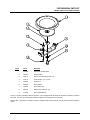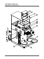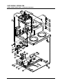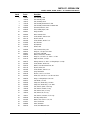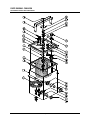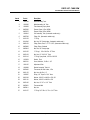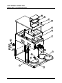
1
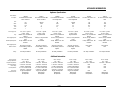
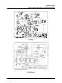
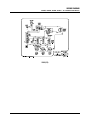
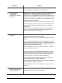
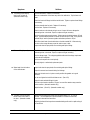
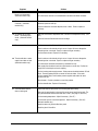
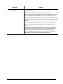
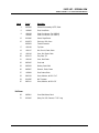
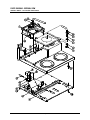
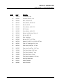
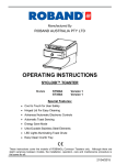
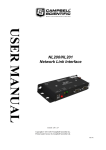
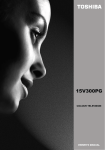
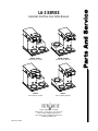
LA-3 SERIES
Automatic And Pour-Over Coffee Brewers
1034505, 1034521
1034506, 1034520
Automatic Brewer, Left Hand
Automatic Brewer, Right Hand
1034516
1034517
Pour-Over Brewer, Left Hand
Pour-Over Brewer, Right Hand
20333 S. Normandie Ave., CA 90502
800-421-6860 • 310-787-5444 • Fax 310-787-5412
USA –E-mail: [email protected]
INT’L E-mail: [email protected]
Website: brewmatic.com
FM CS110 A 6/28/07
TABLE OF CONTENTS
Important Information
Page 3
Appliance Information
Page 4
Wiring Diagrams
Page 5
1034505, 1034506, 1034521 & 1034521 – LA-3 Automatic Brewers
Page 5
1034516 & 1034517 – LA-3 Pour-Over Brewers
Page 6
Troubleshooting Guide
Pages 7 - 13
Parts Diagrams And Parts Lists
Pages 14 – 24
6003093 - Element Pan Assembly W/PTC Black
Page 14
1034505, 1034506, 1034520, 1034521 – LA-3 Automatic Brewers Pages 15 - 18
Tank Assembly – LA-3 Brewers
Pages 19 - 20
1034516 & 1034517 – LA-3 Pour-Over Brewers
Pages 21 - 24
Page 2
IMPORTANT INFORMATION
Read all instructions and safeguards included in the original packaging and in this service manual carefully and
completely before installing, operating or servicing this appliance. Additional copies of installation instructions
and service manuals are available upon request.
The proper performance of service is essential for the safe and effective operation of this appliance. Repairs
should be performed by qualified service personnel only. If you are unable to, or need help servicing this
appliance, contact the nearest Brewmatic Authorized Service Agent or you can contact Brewmatic Company at
800-421-6860.
Only Authorized Replacement Parts Should Be Used. Part substitutions could create a fire hazard and the risk
of personal injury. The use of replacement parts or accessory attachments not recommended by Brewmatic may
be hazardous.
Do Not By-Pass Any Safety Mechanisms Or Operate This Appliance Without Covers In Place. Brewmatic
requires that all safety devices and covers be in place and functioning at all times to guard against a fire hazard
and the risk of personal injury.
Brewmatic Does Not Recommend, And Will Not Furnish Anyone With Information For Changing The Electrical
Rating Of Any Appliance Manufactured Or Distributed By Brewmatic Company. Brewmatic will not approve of
any unauthorized changes to the basic design of this appliance. Any modification or alteration to the appliance
may create a fire hazard, may create a risk of personal injury, may void the safety listings and may void the
warranty.
Plumbing connections - All plumbing connections to water supply lines and drains should be performed by a
licensed plumber complying with all applicable plumbing codes having jurisdiction.
Electrical connections - With the exception of cords with plugs already attached, all electrical connections or
alterations to the power supply should be performed by a licensed electrician complying with all applicable
electrical codes having jurisdiction.
When repairing or replacing internal electrical wiring, in part or in whole, use only terminals and wires with the
same rating, gauge and insulation covering.
When calling for information, parts or service, have the model number, serial number, voltage, wattage, phase
and date of purchase available. Electrical information may be obtained from the electrical information nameplate
located on the appliance.
All procedures, diagrams and specifications contained in this manual are based on the latest information available
at the time of publication. Information, parts and specifications are subject to change without notice.
We assume no liability for any damage to person or property caused by the utilization of this publication to effect
maintenance or repairs.
Due to periodic reviews and changes in safety listing standards, listings and approvals may change at any time.
For current listing and approval information contact Brewmatic.
Page 3
APPLIANCE INFORMATION
Appliance Specifications:
Model Number:
Description:
Volts:
Watts:
Amps:
Hertz:
Phase:
Power Supply Cord:
Plug:
Power Supply Required:
Wall Receptacle Required:
Water Supply Required:
Water Connection:
Listings:
1034505
LA-3 Automatic Brewer With
Faucet. Left Hand.
1034521
LA-3 Automatic Brewer With
Faucet. Leftt Hand.
1034506
LA-3 Automatic Brewer With
Faucet. Right Hand.
1034520
LA-3 Automatic Brewer With
Faucet. Right Hand.
1034516
LA-3 Pour-Over Brewer. Left
Hand.
1034517
LA-3 Pour-Over Brewer. Right
Hand.
120
1700
14.2
60
1
120/240
2220
11
60
1
120
1700
14.2
60
1
120/240
2220
11
60
1
120
1700
14.2
60
1
120
1700
14.2
60
1
6 ft., 2 wire + ground,
15 amp, 14 awg.
NEMA 5-15 P. Furnished and
attached.
120 volt, 15 amp, dedicated
circuit.
15 amp. NEMA 5-15 R. Not
furnished.
6 ft., 3 wire + ground,
15 amp, 14 awg.
Plug Not attached.
6 ft., 2 wire + ground,
15 amp, 14 awg.
NEMA 5-15 P. Furnished and
attached.
120 volt, 15 amp, dedicated
circuit.
15 amp. NEMA 5-15 R. Not
furnished.
6 ft., 3 wire + ground,
15 amp, 14 awg.
Plug Not attached.
6 ft., 2 wire + ground,
15 amp, 14 awg.
NEMA 5-15 P. Furnished and
attached.
120 volt, 15 amp, dedicated
circuit.
15 amp. NEMA 5-15 R. Not
furnished.
6 ft., 2 wire + ground,
15 amp, 14 awg.
NEMA 5-15 P. Furnished and
attached.
120 volt, 15 amp, dedicated
circuit.
15 amp. NEMA 5-15 R. Not
furnished.
240 volt, 15 amp, dedicated
circuit.
Not furnished.
240 volt, 15 amp, dedicated
circuit.
Not furnished.
30 psi min., 80 psi max.
1/4" flared fitting. Flared nut
supplied.
30 psi min., 80 psi max.
1/4" flared fitting. Flared nut
supplied.
30 psi min., 80 psi max.
1/4" flared fitting. Flared nut
supplied.
30 psi min., 80 psi max.
1/4" flared fitting. Flared nut
supplied.
None required.
None.
None required.
None.
ETL safety & sanitation.
ETL safety & sanitation.
ETL safety & sanitation.
ETL safety & sanitation.
ETL safety & sanitation.
ETL safety & sanitation.
60 oz. 12 Cups.
192° - 196°F
3 Increase. 4Decrease
3 Increase. 4 Decrease
1:50 Min., Approximately
5 oz. in 15 to 20 seconds.
4 Increase. 3 Decrease
.25 gpm. Not Adjustable.
Manual Reset.
Not adjustable.
60 oz. 12 Cups.
192° - 196°F
3 Increase. 4Decrease
None
None
None
60 oz. 12 Cups.
192° - 196°F
3 Increase. 4Decrease
None
None
None
None
Manual Reset.
Not adjustable.
None
Manual Reset.
Not adjustable.
Additional Information:
Brewing Capacity:
Brewing Temperature:
Temperature Adjustment:
Beverage Adjustment:
Timer Setting:
Faucet Adjustment:
Flow Control:
Hi-Limit Thermostat:
60 oz. 12 Cups.
192° - 196°F
3 Increase. 4Decrease
3 Increase. 4 Decrease
1:50 Min., Approximately
5 oz. in 15 to 20 seconds.
4 Increase. 3 Decrease
.25 gpm. Not Adjustable.
Manual Reset.
Not adjustable.
60 oz. 12 Cups.
192° - 196°F
3 Increase. 4Decrease
3 Increase. 4 Decrease
1:50 Min., Approximately
5 oz. in 15 to 20 seconds.
4 Increase. 3 Decrease
.25 gpm. Not Adjustable.
Manual Reset.
Not adjustable.
60 oz. 12 Cups.
192° - 196°F
3 Increase. 4Decrease
3 Increase. 4 Decrease
1:50 Min., Approximately
5 oz. in 15 to 20 seconds.
4 Increase. 3 Decrease
.25 gpm. Not Adjustable.
Manual Reset.
Not adjustable.
Page 4
WIRING DIAGRAM
1034505, 1034506, 1034520, 1034521 – LA-3 Automatic Coffee Brewers
120V (Auto)
120/240V (Auto)
Page 5
WIRING DIAGRAM
1034505, 1034506, 1034520, 1034521 – LA-3 Automatic Coffee Brewers
120V (PO)
Page 6
TROUBLESHOOTING
Read and follow the cautions below before attempting to service this coffee brewer.
CAUTION:
Read and verify that the installation instructions have been followed before attempting to operate this appliance.
Incorrect installation or operating procedures will void the warranty and may damage this appliance.
Unplug the power cord before servicing, unless electrical testing is required. Be certain the power supply is of
the correct rating and polarity before connecting the power supply cord. The chassis must be grounded to
prevent possible electric shock. Failure to heed this warning may damage this appliance and may cause injury.
Under no circumstance should the hi-limit thermostat be by-passed. In the event of failure the hi-limit
thermostat should be replaced. Use only original or authorized replacement parts.
Carefully inspect the internal wiring for wear or damage when servicing. Worn or damaged wiring may cause
malfunctions and premature component failures. Replace any wires that have loose connections, damaged
insulation or show evidence of overheating. When repairing or replacing internal electrical wiring, in part or in
whole, use only terminals and wires with the same rating, gauge and insulation covering.
Adjusting the faucet flow beyond factory recommended settings could result in rapid cooling of the faucet flow or
result in excessive faucet head pressure.
Symptoms
1. The coffee brewer will not
operate. The lights and
warmers do not work, and the
coffee brewer will not brew
coffee.
Solutions
Make sure the power supply cord is connected to a proper, working wall
receptacle.
Make sure the "Power" switch has been turned on.
Check the main circuit breaker in the building to see if it has tripped.
Reset or replace the hi-limit thermostat.
Check to make sure the internal wiring is correct. Inspect for loose,
damaged or overheating wires or terminals. Repair or replace wiring as
necessary.
Test the "Power" switch. Replace it if necessary.
Test the power supply cord. Replace it if necessary.
Page 7
Symptoms
2.
The coffee brewer will not
brew coffee. The lights and
warmers work, and the coffee
brewer heats.
Solutions
On automatic models, the start switch must be pressed to initiate a brew
cycle. (Automatic models only.)
On pour-over models, water must be poured in to initiate a brew cycle.
Pour in approximately 60 oz. of water for each brew cycle. See installation
instructions for correct procedures. (Pour-over models only.)
Test the start switch. Replace it if necessary. (Automatic models only.)
Inspect the reservoir and reservoir tubing for blockage.
Check to make sure the internal wiring is correct. Inspect for loose,
damaged or overheating wires or terminals. Repair or replace wiring as
necessary.
Test the timer. Replace it if necessary. (Automatic models only.)
Open the flow control and clean the flow control washer and flow control
screen. (Automatic models only.)
Test the solenoid valve. Replace it if necessary. (Automatic models only.)
If present, check any in-line water filters, check valves or shut-off valves for
proper operation or blockage. (Automatic models only.)
3.
The coffee brewer will not
heat. The brew cycle and
warmers work. The water for
brewing is cold.
Test the thermostat. Replace it if necessary.
Test the thermostat sensor. Replace it if necessary. (See #7)
Test the immersion element. Replace it if necessary.
Check to make sure the internal wiring is correct. Inspect for loose,
damaged or overheating wires or terminals. Repair or replace wiring as
necessary.
4.
The coffee brewer takes much
longer than normal to heat.
The lights and warmers work.
Test the thermostat. Replace it if necessary.
Test the thermostat sensor. Replace it if necessary. (See #7)
Test the voltage supply. The voltage supplied should match the voltage
requirement on the electrical nameplate.
Test the immersion element. Replace it if necessary.
Check to make sure the internal wiring is correct. Inspect for loose,
damaged or overheating wires or terminals. Repair or replace wiring as
necessary.
Page 8
Symptoms
5.
The hi-limit thermostat keeps
activating.
Solutions
Check to make sure the tank has been filled with water. See the installation
instructions for filling procedures.
Test the hi-limit thermostat. Replace it if necessary.
Make sure that the thermostat sensor is inserted all of the way into the well. (See
#7)
Test the brewing temperature. Adjust the thermostat if necessary. (See #7).
Inspect the wiring on the hi-limit thermostat for loose, damaged or overheating
wires or terminals. Repair or replace wiring as necessary.
WARNING
Under no circumstance should the hi-limit thermostat be by-passed. In the event
of failure, the hi-limit thermostat should be replaced. Use only original or
authorized replacement parts.
6.
The coffee brewer trips the
buildings circuit breaker.
Too many appliances are connected on one electrical circuit.
The electrical circuits amperage rating is too low. Locate a correctly rated circuit
or call an electrician to correct this problem.
This coffee brewer may require a dedicated wall circuit or circuit breaker. Check
the electrical specifications.
Check to make sure the internal wiring is correct. Inspect for loose, damaged or
overheating wires or terminals. Repair or replace wiring as necessary.
Inspect the warmer elements for damage. Replace it if necessary.
Inspect the immersion element for damage. Replace it if necessary.
7.
The brewing temperature is
either too hot or too cold.
Make sure that the thermostat sensor is inserted all of the way into the well.
Adjust or replace the thermostat. Turn the adjustment screw clockwise to
increase the temperature, counter-clockwise to decrease. Turn the adjustment
screw a maximum of 1/8 turn per adjustment. Retest and adjust again if
necessary. The recommended temperature is between 192° and 196°F. Test
below the brew cone with water only.
WARNING:
If the thermostat cannot be adjusted properly it should be replaced. The
thermostat is calibrated at the factory and no attempt should be made to
recalibrate it. Use only original or authorized replacement parts.
Test the thermostat sensor with an ohm meter. The sensor should read
approximately 100,000 Ω at a normal room temperature of approximately 25c.
As the heat to the sensor increases, the reading should decrease to zero.
Note: The thermostat sensor must be coated with a thermal mastic heat transfer
compound. (KMP Catalog Number PM8 or equivalent.)
Inspect the inside of the tank for excessive hard water deposits on the thermostat
well. Clean the well if necessary.
Page 9
Symptoms
8.
The brewing cycle is too slow.
Solutions
Inspect and clean the spray head, silicone tubing and siphon fittings.
Do not over tighten the tank lid hold-down screw. (See #10.)
9.
The beverage level is
consistently high or
consistently low. (Automatic
models only.)
Adjust the timer. To increase the beverage level turn the timer adjustment knob
clockwise. To decrease the beverage level turn the adjustment knob
counterclockwise. Turn the adjustment knob 1/2 reference mark maximum per
adjustment. Retest and adjust again if necessary. Note: The marks on the timer
are for reference only and are not intended as an accurate measurement of time.
Test the timer. Replace it if necessary.
Open the flow control and clean the flow control washer and flow control screen.
The flow control washer should be .25 gpm. Incorrect flow washers can cause
inaccurate beverage levels. The code printed on the back of the flow washer
should be “CCP”.
Test the incoming water supply pressure. Water pressure should be between 30
and 80 psi. If the water pressure exceeds 80 psi, install a water pressure
regulator and reduce the water pressure to 50 psi.
10. The beverage level is
inconsistent.
Inspect and clean the spray head, silicone tubing and siphon fittings.
Inspect the reservoir and reservoir tubing for blockage.
Make sure the tank cover is in place correctly and that the gaskets are in good
condition.
Do not over tighten the tank lid hold-down screw. (See page 18, Item #16.) The
screw should be just tight enough to seal the tank. Over tightening the screw can
deform the tank lid causing water leaks and can also change the angle of the
siphon fitting causing inconsistent brew levels
Water or condensation on the timer may cause it to malfunction. Dry the timer
and retest. (Automatic models only.)
Test the incoming water supply for inconsistent water pressure. If the water
pressure is inconsistent, install a water pressure regulator and reduce the water
pressure to minimize water pressure fluctuations. (Automatic models only.)
Test the timer. Replace it if necessary. (Automatic models only.)
If present, check any in-line water filters, check valves or shut-off valves for
proper operation or blockage. (Automatic models only.)
Check the faucet coil fittings inside the tank for leaks. Tighten or replace these
fittings as necessary. (Automatic models only.)
Test the solenoid valve for leaks. Repair or replace it if necessary. (Automatic
models only.)
11. Water drips from the spray
head for a long time after the
brew cycle is finished.
Inspect and clean the spray head, silicone tubing and siphon fittings.
Inspect the reservoir and reservoir tubing for blockage.
Page 10
Symptoms
12. The brewing cycle starts by
itself or will not shut off.
(Automatic models only.)
Solutions
Test the start switch. Replace it if necessary.
Water or condensation on the timer may cause it to malfunction. Dry the timer and
retest.
Check the faucet coil fittings inside the tank for leaks. Tighten or replace these fittings
as necessary.
Test the solenoid valve for leaks. Replace it if necessary.
Test the timer. Replace it if necessary.
Check to make sure the internal wiring is correct. Inspect for loose, damaged or
overheating wires or terminals. Repair or replace wiring as necessary.
Test the incoming water supply pressure. Water pressure should be between 30 and
80 psi. Excessive water pressure can cause the valve to open or leak. If the pressure
exceeds 80 psi, install a pressure regulator and reduce pressure to 50 psi.
Water flow should enter the solenoid valve on the side marked "IN". Water entering
the valve on the wrong side may cause the valve to open or leak.
Inspect and clean the spray head, silicone tubing and siphon fittings.
13. Parts are failing frequently.
Check to make sure the internal wiring is correct. Inspect for loose, damaged or
overheating wires or terminals. Repair or replace wiring as necessary.
Test the voltage supply. The voltage supplied should match the voltage requirement
on the electrical nameplate.
Test the wall receptacle for correct polarity.
Use only original, or authorized, replacement parts.
14. Water leaks from the bottom
of the coffee brewer.
Inspect and clean the spray head, silicone tubing and siphon fittings.
Inspect the reservoir and reservoir tubing for blockage.
Make sure the tank cover is in place correctly and that the gaskets are in good
condition.
Do not over tighten the tank lid hold-down screw. (See #10.)
Inspect the tank and tank fittings for leaks.
The flow control washer should be .25 gpm. Incorrect flow washers may cause the
tank to overflow. (Automatic models only.)
Adjust the timer. (See #9.) (Automatic models only.)
15. The water from the hot water
faucet comes out too fast or
too slow. (Automatic models
only.)
Adjust the faucet adjustment needle valve to approximately 5 oz. in 15 to 20
seconds. Turn the adjustment counterclockwise to increase the faucet flow,
clockwise to decrease the faucet flow.
Adjusting the faucet flow beyond recommended settings will result in rapid cooling of
the faucet flow.
Page 11
Symptoms
16. The water from the hot water
faucet is not hot enough.
(Automatic models only.)
17. The hot water faucet drips
constantly. (Automatic
models only.)
18. No water at the hot water
faucet. The brewing cycle
works. (Automatic models
only.)
19. The warmers will not heat.
Solutions
Make sure that the faucet is adjusted correctly. (See #15.)
The coffee brewer must be on and heated before the faucet will deliver hot water.
Check the faucet seat cup. If the seat cup appears cracked or the material has
hardened, replace the seat cup.
Inspect the faucet for hard water deposits, wear or leaks. Clean or replace as
necessary.
Make sure that the faucet adjustment valve is turned on and adjusted correctly. (See
#15.)
Check the faucet and faucet water lines for blockage.
Test the warmer switch. Replace it if necessary.
Check to make sure the internal wiring is correct. Inspect for loose, damaged or
overheating wires or terminals. Repair or replace wiring as necessary.
Test the warmer element. Replace it if necessary.
20. The solenoid valve or water
supply lines chatter or howl.
(Automatic models only.)
Check to make sure the internal wiring is correct. Inspect for loose, damaged or
overheating wires or terminals. Repair or replace wiring as necessary.
The coffee brewer should be connected to a cold water line only.
Water supply lines should not touch the coffee brewer or counter top. Position the
supply lines so that they do not touch anything.
Test the incoming water supply pressure. Water pressure should be between 30 and
80 psi. Excessive water pressure can cause the valve to chatter. If the water
pressure exceeds 80psi, install a water pressure regulator and reduce the water
pressure to 50 psi.
Water hammer. Contact a plumber to correct this problem.
Test the solenoid valve. Replace it if necessary.
21. The coffee tastes weak or
does not taste good.
Inspect and clean the spray head, silicone tubing and siphon fitting.
Make sure the spray head is in place and the correct spray head is being used. The
spray head should be stainless steel and have 5 holes. (See page 16, Item #47.)
Test the brewing temperature. Adjust if necessary. (See #7.)
Test the brew cycle for correct beverage level. Adjust if necessary. (See #9.)
(Automatic models only.)
Adjust the amount of ground coffee being used.
Adjust the grind of the coffee.
Page 12
Symptoms
22. There are coffee grounds in
the brewed coffee.
Solutions
Test the brew cycle for correct beverage level. (See #9.) Adjust if necessary.
(Automatic models only.)
Inspect the brew cone for wear or damage. Replace it if necessary.
Make sure the spray head is in place and the correct spray head is being used. The
spray head should be stainless steel and have 5 holes. (See page 16, Item #47.)
Adjust the amount of ground coffee being used or adjust the grind of the coffee. Too
much coffee or coffee that is ground too fine may slow the flow of the water through
the coffee.
Make sure that the paper filter being used is correct for this type of coffee brewer.
Two paper filters may have been used accidentally. Use only one filter per brew
cycle.
Fine grind coffees and water softening systems may affect the way the water flows
through the brew cone and coffee, and may cause coffee grounds to appear in the
brewed coffee. There are several options available to help solve this problem:
Extended brew spray heads, wide base brew cones or a paper filter designed for
faster water flow. Call Brewmatic for complete details and options.
Page 13
PARTS DIAGRAM & PARTS LIST
6003093 - Element Pan Assembly W/PTC Black
Item #
Part #
Description
1.
6001020
Element Pan Assembly, Black
2.
6004021
Bracket, Element
3.
9303115
Washer, Lock, With Internal Tooth, 5/16”
4.
9010115
Screw, Machine, 5/16”-18 x 3/4”
5.
9905329
Element, PTC
6.
6000578
Spacer, Element
7.
9905350
Eyelet, Element Pan
8.
9301106
Washer, #10 x .049 Thick, S/S
9.
9918270
Rivet, Tubular Aluminum
The PTC, or Positive Temperature Coefficient element is a self regulating element that adjusts its temperature to maintain a consistent
preset level. The result is an even beverage temperature regardless of the beverage level in the decanter.
Another feature of this element is its ability to operate on voltages between 100 and 240 volts, and still maintain the same temperature
settings.
Page 14
PARTS DIAGRAM - EXTERNAL VIEW
1034505 & 1034506 – LA-3 Automatic Coffee Brewers
Page 15
PARTS LIST - EXTERNAL VIEW
1034505, 1034506,1034520, 1034521 – LA-3 Automatic Coffee Brewers
Item #
Part #
Description
4.
6003093
Element Pan Assembly, W/PTC, Black
5.
1040683
Facia, Hood, Black
9.
1034193
1034206
Panel, Front Access, (For 1034505, 1034521)
Panel, Front Access, (For 1034506, 1034520)
12.
9919461
Switch, Single Rocker
13.
9919463
Switch, Start, Single Rocker
15.
1031112
9920254
Pilot Light
Terminal Connector
16.
9906477
9919457
9901122
9921119
Faucet, Pressure
Seat Cup, Faucet
Aerator, Faucet
Faucet Upper Assy
17.
1034109
Top Cover
18.
1034147
Grid, Pour-In, Plastic, Black
19.
1034148
Cover, Grid, Plastic, Black
20.
9916176
Plug, Snap, 7/8”
21.
1034192
Cover, Back Center
22.
9903435
9903583
Cord, Lead 120V
Cord, Lead 220V
23.
9902329
Bushing, Strain Relief
24.
6000011
Nut, Hex, 1/2”
26.
6000637
Reservoir, Plastic, Brown
27.
1040684
Facia, Bottom, Black
33.
9001229
Screw, Machine, #6-32 x 7/16”
34.
9914285
Nut, Tinnerman
84.
9906103
Fitting, Flared Nut, 1/4”, Brass
85.
9906201
Fitting, Elbow, Flared, 1/4” Tube, Brass
87.
9003141
Screw, Machine, #6-32 x 5/8”
88.
9303124
Washer, Lock, With External Tooth
28.
6000641
Cone, Wide Bottom, Black
75.
9919445
Spring, Coil, S/S, Cleanout, 17-5/8” Long
98.
9918220
Relay (For Model 1034520 & 1034521 Only)
Not Shown
Page 16
PARTS DIAGRAM - INTERNAL VIEW
1034505, 1034506, 1034520, 1034521 – LA-3 Automatic Coffee Brewers
Page 17
PARTS LIST - INTERNAL VIEW
1034505, 1034506, 1034520, 1034521 – LA-3 Automatic Coffee Brewers
Item #
2.
6.
Part #
Description
1034203
1034210
1034197
Tank Assembly, 120V
Tank Assembly, 240V
Tube, Assembly, Faucet
7.
1010198
Tube Assembly, Needle Valve To Tank
8.
1010308
Tube Assembly, Solenoid Valve To Needle Valve
10.
9920526
Thermostat, Electronic, 120v
11.
9920470
Timer, W/Relay Output, 120v
25.
9906201
Fitting, Half Union
30.
9902383
Block, Terminal, 3 Pole
31.
9001162
Screw, Machine, #10-32 x 3/8”
32.
9201110
Nut, Hex, #10-32
33.
34.
9001229
9914285
Screw, Machine, #6-32 x 7/16”
Nut, Tinnerman
35.
9914354
Nut, Expansion
36.
1034196
Bracket, Valve
37.
9922229
Valve, Solenoid, 2 Way, 120v
38.
9906416
Fitting, 90°, 1/8” Pipe x 5/16” Hose
39.
40.
9906561
9906434
9920130
Flow Control, .250 GPM
Washer, Flow Control, .250 GPM
Fitting, Tee, 1/4” Tube x 1/4” Tube x 1/ 4” Tube
41.
9914173
Nipple, Hex, Brass, 1/4” Pipe
42.
6000747
Bushing, Reducer, 1/4” Flare x 1/2” Straight Pipe x 1/4” Pipe
43.
9001208
Screw, Machine, #8-32 x 5/8”
44.
9303104
Washer, Lock, With Internal Tooth, #8
45.
9201145
Nut, Hex, #8-32, S/S
46.
9001258
Screw, Machine, #10-32 x 1/4”
47.
1031320
Spray, Head Brewer
48.
9202120
Nut, Hex, 1/8”-27 x 1/16” Thick
49.
9907223
Gasket, S/S, 13/32” ID x 11/16” OD x .032 Thick
50.
6000792
Fitting, 1/8” Straight Pipe x 5/16” Hose
51.
9922217
Valve Needle, 1/4” Tube
52.
9903549
Clamp, Hose, Double Tang, 1/2” Diam.
53.
9903550
Clamp, Hose, Double Tang, 11/16” Diam.
54.
1031268
Tube, Silicone, Siphon, 3-5/8“ Long
55.
1034160
Tube, Silicone, Overflow, 8“ Long
56.
1010029
Tube, Silicone, Drain, 16“ Long
57.
1032316
Tube, Silicone, Fill, 27“ Long
58.
1034161
Tube, Silicone, Connection, 4-1/2“ Long
59.
9902346
Drain Plug, Bumper Stem
67.
9301205
Washer, #10, 13/64” x 11/16”, S/S
82.
9919521
Sensor, Thermostat
83.
6000800
Shield, Thermostat
86.
9004104
Screw, Sheet Metal, #6 x 3/8”
Page 18
PARTS DIAGRAM - TANK VIEW
LA-3 Automatic and Pour-Over Coffee Brewers
Page 19
PARTS LIST - TANK VIEW
LA-3 Automatic and Pour-Over Coffee Brewers
Item #
Part #
Description
1.
1034199
Weld Assembly, Tank
2.
1034202
Weld Assembly, Lid, Tank
3.
1034028
Tube Assembly, Spray Head
4.
9905356
9905370
Element, Spiral, 120v 1300W
Element, Spiral, 220v 1600W
5.
1034010
Coil Assembly, Tank, (Automatic models only.)
6.
6000768
Fitting, Coil, (Automatic models only.)
7.
9915153
“O” Ring
8.
9914240
Nut, Hex, 3/8” Straight pipe, (Automatic models only.)
9.
9906154
Fitting, Elbow, Flare, 1/4”T To 1/8”P, (Automatic models only.)
10.
6000826
Fitting, Elbow, Soldered
11.
6000818
Nut, Hex, 3/8” Straight pipe
12.
9915155
“O” Ring, 1. OD x .864 ID x .07 Thick
13.
9202123
Nut, Hex, 1/2”-20 5/16” Thick
14.
9915110
“O” Ring, Spray Head, .487 ID x .693 OD
15.
1010254
Gasket, Tank
16.
9001261
Screw, Machine, 10-32 x 1-1/8”
17.
1034125
Adjustment Plate
18.
1034009
Bracket Assembly, Tank Lid
19.
9920436
Thermostat, Hi Heat Limiter, 120v
20.
9201152
Nut, Hex, #6-32 x 1/4”
21.
1040587
Fitting, 1/8” Taper P x 5/16” Hose
22.
9301203
Washer, .628 OD x .406 ID x .032, S/S
23.
9301181
Washer, .628 OD x .406 ID x .032
24.
9202120
Nut, Hex, 1/8”-27 x 1/16” Thick
25.
6000831
Thermostat Well
26.
6000011
Nut, Hex
27.
9915157
“O” Ring, 3/8” OD x 1/4” ID x 1/16” Thick
Page 20
PARTS DIAGRAM - EXTERNAL VIEW
1034516 & 1034517 – LA-3 Pour-Over Coffee Brewers
Page 21
PARTS LIST - EXTERNAL VIEW
1034516 & 1034517 – LA-3 Pour-Over Coffee Brewers
Item #
Part #
Description
4.
6003093
Element Pan Assembly, W/PTC, Black
5.
1040692
Facia, Hood, Black
9.
1034193
1034206
Panel, Front Access, (For 1034516)
Panel, Front Access, (For 1034517)
12.
9919486
Switch, Single Rocker
15.
9916278
9920254
Pilot Light, 125v, Green
Terminal Connector
17.
1034109
Top Cover
18.
1034147
Grid, Pour-In, Plastic, Black
19.
1034148
Cover, Grid, Plastic, Black
20.
9916176
Plug, Snap, 7/8”
21.
1034192
Cover, Back Center
22.
9903435
Cord, Lead
23.
9902329
Bushing, Strain Relief
26.
6000637
Reservoir, Plastic, Brown
27.
1040684
Facia, Bottom, Black
33.
9001229
Screw, Machine, #6-32 x 7/16”
34.
9914285
Nut, Tinnerman
87.
9003141
Screw, Machine, #6-32 x 5/8”
28.
6000641
Cone, Wide Bottom, Black
75.
9919445
Spring, Coil, S/S, Cleanout, 17-5/8” Long
Not Shown
Page 22
PARTS DIAGRAM - INTERNAL VIEW
1034516 & 1034517 – LA-3 Pour-Over Coffee Brewers
Page 23
PARTS LIST - INTERNAL VIEW
1034516 & 1034517 – LA-3 Pour-Over Coffee Brewers
Item #
Part #
Description
2.
1034214
Tank Assembly, 120v
10.
9920526
Thermostat, Electronic, 120v
30.
9902383
Block, Terminal, 3 Pole
31.
9001162
Screw, Machine, #10-32 x 3/8”
32.
9201110
Nut, Hex, #10-32
33.
9001229
Screw, Machine, #6-32 x 7/16”
34.
9914285
Nut, Tinnerman
43.
9001208
Screw, Machine, #8-32 x 5/8”
44.
9303104
Washer, Lock, With Internal Tooth, #8
45.
9201145
Nut, Hex, #8-32, S/S
47.
1031320
Spray, Head Brewer
48.
9202120
Nut, Hex, 1/8”-27 x 1/16” Thick
49.
9907223
Gasket, S/S, 13/32” ID x 11/16” OD x .032 Thick
50.
6000792
Fitting, 1/8” Straight Pipe x 5/16” Hose
52.
9903549
Clamp, Hose, Double Tang, 1/2” Diam.
53.
9903550
Clamp, Hose, Double Tang, 11/16” Diam.
54.
1031268
Tube, Silicone, Siphon, 3-5/8” Long
55.
1034160
Tube, Silicone, Overflow, 8” Long
56.
1010029
Tube, Silicone, Drain, 16” Long
58.
1034161
Tube, Silicone, Connection, 4-1/2” Long
59.
9902346
Drain Plug, Bumper Stem
82.
9919521
Sensor, Thermostat
83.
6000800
Shield, Thermostat
Page 24