1
OWNER’S MANUAL
Safety, Assembly, Operating, and Maintenance Instructions
and ILLUSTRATED PARTS MANUAL
Model MB (18 HP)
™
Please Read and Save These Instructions
For Safety, Read All Safety and Operation
Instructions Prior to Operating Machine
Effective Date: 09-01-06
P/N 4000-3
Foreword
Thank you. . .for purchasing a Walker mower. Every effort has been made to provide you with the
most reliable mower on the market, and we are sure you will be among our many satisfied customers. If for any reason this product does not perform to your expectations, please contact us at (970)
221-5614. Every customer is important to us. Your satisfaction is our goal.
Please. . .read this manual thoroughly! This manual is to be used in conjunction with the engine
manufacturer's manual for the specific engine on the mower model you have purchased. Before you
operate your new mower, please read this entire manual. Some of the information is crucial for proper operation and maintenance of this mower - it will help protect your investment and ensure that the
mower performs to your satisfaction. Some of the information is important to your safety, and must
be read and understood to help prevent possible injury to the operator or others. If anything in this
manual is confusing or hard to understand, please call our service department, at (970) 221-5614,
for clarification before operating or servicing this mower.
This manual covers Model MB with the Briggs & Stratton Vanguard 18 HP gasoline engine.
All shields and guards must be in place for the proper and safe operation of this machine.
Where they are shown removed in this manual, it is for illustration purposes only. Do not operate
this machine unless all shields and guards are in place.
Specifications given are based on the latest information available at the time this manual was
produced.
Walker Mfg. Co. is continually striving to improve the design and performance of its products. We
reserve the right to make changes in specifications and design without thereby incurring any obligation relative to previously manufactured products.
Sincerely,
WALKER MANUFACTURING COMPANY
Bob Walker, President
Table of Contents
Owner’s Manual
General Information ________________
3
HIGHLIGHTED INFORMATION _____________
GLOSSARY ____________________________
IDENTIFYING NUMBER LOCATIONS________
ENGINE SERIAL NUMBER LOCATION ______
SERVICING OF ENGINE AND
DRIVETRAIN COMPONENTS ______________
3
3
3
4
Specifications
4
_______________________ 5
Component Identification ___________
8
Safety Instructions _________________
11
BEFORE OPERATING ___________________
OPERATING ___________________________
MAINTENANCE ________________________
SAFETY, CONTROL, AND
INSTRUCTION DECALS _________________
11
12
13
Assembly Instructions
15
_____________ 17
SETUP INSTRUCTIONS _________________
Battery Service _______________________
Mower Deck Assembly ________________
Deck Caster Wheels Installation ________
Deck Discharge Shield Installation ______
PTO Shaft Guard Installation __________
Tilt-Up Roller Wheel Installation ________
Mower Deck Installation on Tractor ______
Deck Installation ____________________
Deck Leveling ______________________
PREOPERATING CHECKLIST ____________
17
17
17
17
17
18
18
18
18
20
21
Operating Instructions _____________
24
CONTROL IDENTIFICATION,
LOCATION, AND FUNCTION _____________
Ignition Switch _______________________
Engine Choke ________________________
Engine Throttle_______________________
Forward Speed Control (FSC)___________
Steering Levers ______________________
Blade Clutch (PTO) ___________________
Parking Brake ________________________
Transaxle Lockout Rods _______________
Hourmeter ___________________________
STARTING THE ENGINE _________________
ADJUSTING GROUND
SPEED AND STEERING _________________
24
24
25
25
25
25
25
26
26
26
28
ENGAGING THE MOWER ________________
STOPPING THE MACHINE _______________
ADJUSTING CUTTING HEIGHT ___________
TRANSAXLE LOCKOUTS________________
RECOMMENDATIONS FOR MOWING ______
RECOMMENDATIONS FOR TILT-UP DECK
OPERATION/TRANSPORT _______________
30
31
31
32
32
33
Maintenance Instructions___________34
MAINTENANCE SCHEDULE CHART _______ 34
IMPORTANT TIPS FOR CARE OF THE
BRIGGS & STRATTON ENGINE___________ 35
Fuel System _________________________ 35
Starting _____________________________ 35
Cooling System ______________________ 35
Air Cleaner __________________________ 35
Oil _________________________________ 35
LUBRICATION _________________________ 36
Engine Oil___________________________ 36
Engine Break-In Oil ___________________36
Checking Engine Crankcase Oil Level ____36
Changing Engine Crankcase Oil/Oil Filter _36
Grease Fitting and Oil Point Lubrication__ 37
Mower Deck Gearbox Lubrication _______ 40
Transaxle Lubrication _________________ 40
Transaxle Oil and Filter Change_________ 40
CLEANING ____________________________ 41
Engine Air Cooling System ____________ 41
Air Cleaner System ___________________ 42
Grass Buildup in Mower Housing _______ 42
Transaxle Cooling Fins ________________ 43
CHECKING/SERVICING _________________ 43
Security of Air Cleaner System _________ 44
Battery _____________________________ 44
Cleaning the Terminals ________________44
Charging the Battery __________________44
Tire Pressure ________________________ 44
Wheel Nuts Torque ___________________ 44
Sharpen Mower Blades ________________ 44
Drive Belts __________________________ 45
Mower Deck Gearbox Oil Seals _________ 45
Spark Plugs _________________________ 46
Breaker Points _______________________ 46
Fuel Lines and Clamps ________________ 46
Blade Brake Action ___________________ 46
28
1
Table of Contents
REPLACING/REPAIRING ________________
Drive Belts __________________________
Engine/PTO Belt ____________________
Ground Drive Belt ___________________
Fuel Filter ___________________________
Blade Overload Shear Bolts ____________
PTO Shear Pin _______________________
Mower Blades ________________________
ADJUSTMENTS ________________________
Transmission Control _________________
Steering Lever Position Adjustment _____
Steering Handles Adjustment __________
Neutral Position Adjustment ___________
Full Forward Speed Adjustment ________
Straight Tracking Adjustment __________
Neutral Switch Adjustment ____________
Forward Speed Control Friction Adjustment
Tilt-Up Deck Adjustable Stop ___________
PTO Belt Tension _____________________
PTO Clutch __________________________
Clutch Rod __________________________
ELECTRICAL SYSTEM __________________
46
46
47
48
49
49
49
50
51
51
51
51
52
53
53
54
54
54
55
55
55
55
Illustrated Parts Manual
TRACTOR DECALS _____________________
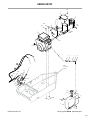
BODY / CHASSIS ASSEMBLY ____________
MAIN COMPONENT
POWER TRANSMISSION ________________
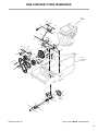
ENGINE GROUP _______________________
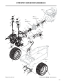
HYDROSTATIC GROUND
DRIVE ASSEMBLIES ____________________
STEERING CONTROL ASSEMBLIES _______
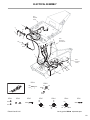
ELECTRICAL ASSEMBLY________________
LIGHT KIT / SPREAD TAIL WHEEL AXLE KIT
WIRING SCHEMATIC____________________
Warranty ___________________________
2
56
58
60
62
64
66
68
70
72
73
General Information
HIGHLIGHTED INFORMATION
Walker Manufacturing recommends that any service requiring special training or tools be performed
by an authorized Walker Mower Dealer. There are
several general practices to be aware of in the area
of safety. Most accidents associated with the operation or maintenance of a Walker Mower are
caused by disregarding basic safety precautions or
specific warnings. Such accidents, in most cases,
can be prevented by being aware of the dangers
present.
Information of special importance has been highlighted in bold type in this manual. Refer to Safety
Instructions for the meanings of DANGER, WARNING, CAUTION, IMPORTANT, and NOTE.
GLOSSARY
There are many terms that are either unique to this
equipment or that are used as acronyms. The following terms and their definitions will help while
using this manual:
•
•
•
STEERING LEVERS steer the tractor by controlling the two transaxles.
•
TRACTOR is the prime mover, including the engine, drive train, operator seat, and controls to
operate the mower.
•
TRANSAXLE LOCKOUT RODS release the
transaxles to permit freewheeling the tractor.
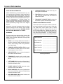
IDENTIFYING NUMBER LOCATIONS
The tractor serial number plate is affixed to the tractor body just below the left rear corner of the seat.
The mower deck serial number plate is affixed
alongside the angle iron framing on the LH side of
the LH mower blade drive. Model and serial numbers are helpful when obtaining replacement parts
and maintenance assistance. For ready reference,
please record these numbers in the space provided.
Tractor Model No. _______________________
Tractor Serial No. _______________________
DECK is the mowing attachment mounted on
the front of the tractor which includes the carrier
frame, deck housing, blade drive gearboxes,
and cutter blades.
FORWARD SPEED CONTROL (FSC) controls
the maximum forward speed of the tractor;
functioning as a cruise control.
•
GROUND DRIVE refers to the dual transaxles
which drive the main wheels.
•
TRANSAXLE transmits and controls power
from the ground drive belt to the main drive
wheel.
•
LEFT HAND (LH) refers to the left-hand side of
the tractor when the operator is seated facing
forward in the tractor seat.
•
POWER TAKE-OFF (PTO) transmits engine
power to run the cutter blades.
•
RIGHT HAND (RH) refers to the right-hand side
of the tractor when the operator is seated facing
forward in the tractor seat.
•
SIDE DISCHARGE (SD) mows but does not
collect the mowed material.
Deck Serial No.
_______________________
Engine Model No. _______________________
Engine Serial No. _______________________
Date of Purchase _______________________
Fill In By Purchaser
3
General Information
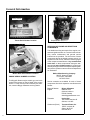
Serial Number
Tractor Serial Number Location
Serial Number
Engine Serial Number Location
SERVICING OF ENGINE AND DRIVETRAIN
COMPONENTS
Serial Number
Mower Deck Serial Number Location
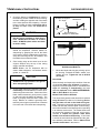
ENGINE SERIAL NUMBER LOCATION
The Briggs & Stratton engine model, type, and code
numbers are located on the left hand of the engine
shroud. For the mower model covered by this manual, contact a Briggs & Stratton servicing dealer.
4
The detailed servicing and repair of the engine, transaxle and gearboxes are not covered in this manual.
Only routine maintenance and general service
instructions are provided. For the service of these
components during the limited warranty period, it is
important to find a local, authorized servicing agent
of the component manufacturer. Any unauthorized
work done on these components during the warranty period may void the warranty. If you have any
difficulty finding an authorized outlet or obtaining warranty service, please contact our Service Department
for assistance:
Walker Manufacturing Company
5925 E. Harmony Road
Fort Collins, CO 80528
1-970-221-5614
Service manuals are available for each of these
components from their respective manufacturers as
follows:
Briggs & Stratton
Engine
Briggs & Stratton
800-233-3723
(24-hour hotline in
USA & Canada)
www.briggsandstratton.com
Transaxle
Hydro-Gear
1411 South Hamilton St.
Sullivan, IL 61951
Gearboxes (Deck)
Tecumseh Power Co.
1555 S. Jackson St.
Salem, IN 47167
812-883-3575
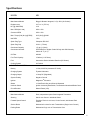
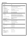
Specifications
MODEL
MB
ENGINE
Manufacturer/Model
Briggs & Stratton Vanguard, 2 Cyl. OHV (Air-Cooled)
Displacement
34.7 cu. in. (570 cc)
HP (@ 3600 RPM)
18.0
Max. RPM (No Load)
3600 ± 100
Governed RPM
3600 ± 100
Max. Torque [ft-lb (N⋅ m) @ RPM]
29.5 (40.5) @ 2400
Idle RPM
1750
Spark Plug Type
Champion RC14YC
Spark Plug Gap
.030 in. (.75 mm)
Crankcase Capacity
1.5 qts (1.4 liters)
Crankcase Lubricant
SF/SG/SH/SJ or Higher Grade Oil Only with 30W Viscosity
Above 40° F (4° C)
Oil Filter
492932
Fuel Tank Capacity
3 Gallons (11.35 liters)
Fuel
Automotive Grade Unleaded Gasoline (85 Octane)
Cooling System
Air Cooled
ELECTRICAL SYSTEM
Battery
12 Volt, 220 CCA (Interstate PC12/80)
Charging System
Flywheel Alternator
Charging Output
16 Amp DC (Regulated)
System Polarity
Negative Ground
Ignition
Magnetron® Electronic
Starter
12 Volt Electric Key and Solenoid Operated
Interlock Switch
Ignition Lockout by Seat Switch, Transmission Neutral and Blade Clutch
Circuit Breaker
Manual Reset (15A)
TRANSMISSION
Manufacturer/Model
Dual, Independent Hydro-Gear Integrated Transaxles
Steering
Hand Lever Control / Individual Wheel
Forward Speed Control
Precision Friction Lock Lever, Cruise Control, with Neutral-Park
Position
Service Brake
Mechanical Lockout for each Transmission (Single Lever Control)
Parking Brake
Mechanical Cog Lock on Transmission Gear
5
Specifications
MODEL
MB
TRANSMISSION (continued)
Neutral
Transmission Release by Manual Dump Valve
Final Drive
Direct Drive Axle from Transaxle
Transmission Fluid
Factory Service
20W50 Multi-Viscosity Motor Oil (Minimum SL Grade Oil)
Transmission Fluid Capacity
79 fl oz (2336 ml)
Transmission Cooling
Cooling Fan Mounted on Drive Pulley
Ground Travel Speed
Forward m.p.h. (km/h)
Reverse m.p.h. (km/h)
0-8 (0-13) Infinitely Variable
0-8 (0-13) Infinitely Variable
BLADE DRIVE
PTO Shaft
Sliding Spline Shaft with Two (2) High-Speed U-Joints
Blade Spindle
Each Blade (2) Mounts Direct on Peerless Right Angle
Gearbox with Tee Gearbox in Center Connected to PTO Shaft
(Complete Geared Drive, Peerless Model 1000 Gearboxes)
Blade Drive Clutch and Brake
Mechanical Clutch with Internal Brake [Stops Blades within Five (5)
Seconds of Disengagement]
Max. Blade Speed
[22 in. (56 cm) Blade] @ 3600
RPM Engine
2900 RPM
[16700 FPM (5090 m/min)]
TIRE SIZE
Deck Caster Wheel
2.80/2.50-4 Pneumatic (4-Ply)
Deck Caster Wheel (Optional)
8 x 3.00-4 Foamed Rubber
Drive
18 x 8.50-10 (4-Ply Low-Profile)
Rear
13 x 6.50-6 (4-Ply)
TIRE PRESSURE
Deck Caster Wheel
20 PSI (137 kPa)
Drive
15 PSI (103 kPa)
Rear
20 PSI (137 kPa)
DIMENSIONS (Tractor and Mower)
Length
82 in. (208 cm)
Width
6
36 in. (91 cm) SD Model
(with Deflector)
41-3/4 in. (106 cm)
42 in. (107 cm) SD Model
(with Deflector)
47-3/4 in. (121 cm)
Specifications
MODEL
MB
DIMENSIONS (continued)
48 in. (122 cm) SD Model
(with Deflector)
53-3/4 in. (137 cm)
56 in. (142 cm) SD Model
(with Deflector)
61-3/4 in. (157 cm)
Height
39 in. (99 cm)
Wheel Base (Tractor)
38-1/2 in. (98 cm)
Tread Width (Tractor)
29-3/4 in. (76 cm)
MOWER DECK
Width of Cut
36-, 42-, 48-, or 56-in. (91, 107, 122 or 142 cm)
Cutting Height
1 to 4 in. (3 to 10 cm)
Height Adjustment
7 Positions - 1/2 in. (1 cm) Increment Hitch Pins Installed in
Multi-Position Deck Support
Blade Size
36 in. (91 cm) SD Model
20 in. (51 cm) Two (2) Clockwise-Rotating Blades with a 4 in.
(10 cm) Center Overlap
42 in. (107 cm) SD Model
22 in. (56 cm) Two (2) Clockwise-Rotating Blades with a 2 in.
(5 cm) Center Overlap
48 in. (122 cm) SD Model
25 in. (64 cm) Two (2) Clockwise-Rotating Blades with a 2 in.
(5 cm) Center Overlap
56 in. (142 cm) SD Model
20 in. (51 cm) Three (3) Clockwise-Rotating Blades with a 2 in.
(5 cm) Center Overlap
Deck Suspension
Torsion-Flex Frame with Caster Wheels and
Counterweight Springs
CURB WEIGHT (Approximate)
Tractor Only
551 lb (250 kg)
SD Tractor and 36 in. SD Deck
696 lb (316 kg)
SD Tractor and 42 in. SD Deck
731 lb (332 kg)
SD Tractor and 48 in. SD Deck
756 lb (343 kg)
DRIVE BELTS
Engine PTO
Walker P/N 4230
Ground Drive
Walker P/N 4248
SEAT
Contour-Molded, with Nylon Backed Vinyl Cover and Integral
Foam Cushion
FRAME/BODY CONSTRUCTION
Frame/Body
3/16 Plate Steel
Deck
11 Gauge Steel
NOTE: The manufacturer reserves the right to make changes in specifications shown herein at any time
without notice or obligation.
7
Component Identification
NOTE: Control Identification
shown in Operating
Instructions section.
Tilt-Up Latch
Counterweight Spring and
Protective Cover
Deck Support
Arm
Forward Speed
Control (FSC)
Friction
Adjustment
Tilt-Up
Deck Handle
Deck Support Arm
Deck Lift Handle
(Cutting Height Adjustment)
Footrests
Tilt-Up
Hook
Deck Discharge Shield
Footrests
Front View and Right Side View
8
Deck Support
Pin and Height
Adjustment
Hitch Pins
Deck
Caster Wheels
Component Identification
Oil Fill
Fuel
Filter
Oil Dipstick
Tailpipe
Fuel Pickup
Line
Muffler
Cylinder Head
Cooling Fins
Left Hand
Drive Wheel
Fuel Tank
and Cap
Tailwheel Fork
and Wheel
Rear View and Left Side View
9
Component Identification
Steering Levers
Dampening Springs
LH Transmission
Control Arm
RH Transmission
Control Arm
LH Transaxle
Expansion
Reservoir
RH Transaxle
Expansion
Reservoir
LH Transaxle
RH Transaxle
RH Transaxle
Lockout Rod
LH Transaxle
Lockout Rod
Parking Brake
Linkage
Positive (+)
Battery Cable
Negative (-)
Battery Cable
Fuel Tank
Fuel Pump
Fuel Tank Cap
Parking Brake
PTO Clutch
Lever
Flexible PTO
Spider Coupling
Fuel Filter
Air Cleaner
Cover Latch
Fuel Pickup Line
Oil Fill
Air Cleaner Cover
Oil Dipstick
RH Tail Weight
LH Tail Weight
Rubber Bumpers
(Body Support)
Muffler Heat
Shield
Top View (Body Raised)
10
Safety Instructions
Pay particular attention to any information labeled
DANGER, WARNING, CAUTION, IMPORTANT,
and NOTE in this manual.
When you see the Safety Alert Symbol (
),
read, understand, and follow the instructions. Failure to comply with safety instructions may result in
personal injury.
The seriousness or degree of importance of each
type of information is defined as follows:
DANGER
An IMMEDIATE hazard that WILL result in
severe personal injury or DEATH, if warning is ignored and proper safety precautions are not taken.
Walker Manufacturing cannot predict every potentially dangerous situation. Therefore, items labeled
as such in this manual do not cover all conceivable
situations. Any person using procedures, tools, or
control techniques not recommended by Walker
Manufacturing must take full responsibility for safety.
The Walker Rider Lawnmower has been designed
with many safety features to protect the operator
from personal harm or injury. However, it is necessary
for the operator to use safe operating procedures at
all times. Failure to follow safety instructions
contained in this manual may result in personal
injury or damage to equipment or property.
If you have any questions concerning setup, operation, maintenance, or safety, please contact your
authorized Walker Mower Dealer or call Walker
Manufacturing Company at (970) 221-5614.
BEFORE OPERATING
WARNING
1.
A POTENTIAL hazard that COULD result in
severe personal injury or DEATH, if warning is ignored and proper safety precautions are not taken.
Walker Manufacturing Company
5925 East Harmony Road
Fort Collins, CO 80528
CAUTION
Possible hazards or unsafe practices that
MAY result in MODERATE personal injury
or property damage, or machine damage, if
warning is ignored and proper safety precautions are not taken.
IMPORTANT: Identifies mechanical information
demanding special attention, since it deals with the
possibility of damaging a part or parts of the
machine.
NOTE: Identifies information worthy of special
attention.
Read and understand the contents of this
Owner's Manual before starting and operating the machine. Become thoroughly familiar
with all machine controls and how to stop the
machine and disengage the controls quickly.
Replacement Owner's Manuals are available by
sending the Model and Serial Number to:
2.
Never allow children to operate rider mower.
Do not allow adults to operate without proper
instruction.
3.
Clear the area to be mowed of any foreign
objects which may be picked up and thrown by
cutter blades. Pick up all sticks, stones, wire,
and any other debris.
4.
Keep everyone, especially children and pets, a
safe distance away from the area being mowed.
Do not mow with bystanders in the area.
5.
Do not operate the machine barefoot or wearing
sandals, sneakers, tennis shoes, or similar lightweight footwear. Wear substantial protective
footwear.
11
Safety Instructions
6.
7.
8.
9.
Do not wear loose fitting clothing that could get
caught in moving parts. Do not operate this
machine while wearing shorts; always wear
adequate protective clothing, including long
pants. Wearing safety glasses, safety shoes,
and a helmet is advisable and required by some
local ordinances and insurance regulations.
Prolonged exposure to loud noise can cause
impairment or loss of hearing. Operator hearing protection is recommended. Wear a
suitable hearing protective device, such as earmuffs or earplugs.
Keep all protective shields and safety devices in place. If a protective shield, safety
device, or decal is damaged, unusable, or missing, repair or replace it before operating the
machine.
Be sure interlock switches are functioning
correctly, so the engine cannot be started unless the Forward Speed Control lever is in the
NEUTRAL-PARK position, and the PTO clutch
is in the DISENGAGED position. Also, the
engine should stop if the operator lifts off the
seat with the PTO clutch in the ENGAGED
position.
12. The electrical system battery contains sulfuric
acid. Avoid any contact with skin, eyes, and
clothing. Keep the battery and acid out of reach
of children.
OPERATING
1.
Operate the mower only in daylight or in good
artificial light with good visibility of the area being
mowed.
2.
Sit on the seat when starting the engine and
operating the machine. Keep feet on the deck
footrests at all times when the tractor is moving
and/or mower blades are operating.
3.
For a beginning operator, learn to steer
(maneuver) the tractor with a slow engine
speed before attempting any mowing operation. Be aware that, with the front mounted
mower configuration, the back of the tractor
swings to the outside during turns.
4.
Remember, for an emergency stop, the forward
motion of the tractor can always be stopped by
pulling the Forward Speed Control (FSC) into
the NEUTRAL-PARK position.
5.
In case the transmission drive belt breaks during
operation, and if the machine is on a slope, the
machine will freewheel down the slope. To
maintain control, immediately (1) Release the
steering levers and simultaneously (2) Move the
FSC to the NEUTRAL-PARK position. When
the machine is stopped or moving slowly,
engage the parking brake.
10. Handle gasoline with care. Gasoline is highly
flammable and its vapors are explosive:
12
a.
Use an approved fuel container.
b.
Never add fuel to a running engine or hot
engine (allow hot engine to cool several
minutes).
c.
Keep matches, cigarettes, cigars, pipes,
open flames, or sparks away from the fuel
tank and fuel container.
NOTE: This is exactly the same procedure used to
normally stop and park the machine.
6.
Disengage the blade clutch and put the FSC in
the NEUTRAL-PARK position before starting
the engine (an ignition interlock switch normally
prevents starting of the machine if these controls
are in the OPERATING position).
d.
Always fill the fuel tank outdoors using care.
Fill to about one inch from the top of the tank.
Use a funnel or spout to prevent spilling.
e.
Replace the machine fuel cap and container
cap securely and clean up any spilled fuel
before starting the engine.
7.
Do not run the engine in a confined area
without adequate ventilation. Exhaust fumes
are hazardous and can be deadly.
11. Never attempt to make any adjustments
while the engine is running, except where specifically instructed to do so.
8.
Do not carry passengers - maximum seating
capacity is one (1) person.
Safety Instructions
9.
Watch for holes, rocks, and roots in the terrain
and for other hidden hazards. When mowing
tall grass, mow higher than desired to expose
any hidden obstacles. Then, clean the area and
mow to the desired height.
16. In case of a clogged or plugged mower deck:
10. Avoid sudden starts or stops. Before backing
the machine up, look to the rear to be sure no
one is behind the machine. Watch carefully for
traffic when crossing or working near roadways.
11. Disengage the blade drive when transporting
the machine across drives, sidewalks, etc. Never
raise the mower deck while blades are
rotating.
12. The maximum recommended side slope
operating angle is 20 degrees or 33% grade.
When operating the machine on a slope, reduce
speed and use caution to start, stop, and
maneuver. To prevent tipping or loss of control
of the machine, avoid sharp turns or sudden
changes in direction.
13. Never adjust cutting height with the engine
running. Before adjusting cutting height or
servicing, disengage the blade clutch (PTO),
stop the engine, and remove the ignition key.
Wait for all movement to stop before getting off
the seat.
NOTE: The clutch brake should normally stop
drive line rotation within five (5) seconds of disengaging the PTO clutch.
14. For side discharge mower decks, do not operate with the grass deflector chute removed.
Keep the deflector in the lowest possible
position.
a.
Disengage the blade clutch (PTO) and turn
the engine off before leaving the seat.
b.
LOOK to make sure blade drive shaft movement has stopped before trying to unclog
the system.
c.
Disconnect the spark plug wires.
d.
Never place hands under the deck use a
stick or similar tool to remove clogged material.
17. If the cutting blades strike a solid object or the
machine begins to vibrate abnormally,
immediately disengage the blade clutch
(PTO), stop the engine, and wait for all
moving parts to stop. To prevent accidental
starting, disconnect the spark plug wires.
Thoroughly inspect the mower and repair any
damage before restarting the engine and
operating the mower. Make sure cutter blades
are in good condition and blade nuts are torqued
to 60 ft-lb (81.3 N⋅ m).
18. Do not touch the engine or muffler while the
engine is running or immediately after stopping the engine. These areas may be hot
enough to cause serious burns.
19. When leaving the machine unattended, disengage the blade clutch (PTO), stop the
engine, and remove the key.
MAINTENANCE
1.
To prevent accidental starting of the engine
when servicing or adjusting the machine, remove the key from the ignition switch and disconnect the spark plug wires.
15. When using the tilt-up deck, observe the following recommendations:
a.
Do not move tractor with deck in tilt-up position.
2.
To reduce fire hazards, keep the engine free of
grass, leaves, excessive grease, and dirt.
b.
Never tilt body forward with deck in tilt-up
position.
3.
Keep all nuts, bolts, and screws tight to ensure
the machine is in a safe, working condition.
Check the blade mounting nuts frequently, making sure they are tight.
4.
Perform only maintenance instructions described in this manual. Unauthorized maintenance operations or machine modifications
may result in unsafe operating conditions.
13
Safety Instructions
5.
If the engine must be running to perform a maintenance adjustment, keep hands, feet, and
clothing away from moving parts. Do not wear
jewelry or loose clothing.
6.
Always use the proper engine service
manual when working on the engine.
Unauthorized maintenance operations or
modifications to the engine may result in
unsafe operating conditions.
7.
Altering the equipment or engine in any manner
which adversely affects its operation, performance, durability, or use will VOID the warranty
and may cause hazardous conditions.
8.
Never attempt to disconnect any safety devices
or defeat the purpose of these safety devices.
9.
Do not change the engine governor settings or
overspeed the engine. The governor has been
factory-set for maximum-safe engine operating
speed.
10. Use genuine factory replacement parts. Substitute parts may result in product malfunction
and possible injury to the operator and/or
others.
14
11. Use care when charging the battery or performing maintenance on the battery and
electrical system:
a.
Make sure the battery charger is unplugged
before connecting or disconnecting cables
to the battery.
b.
Charge the battery in a well-ventilated
space, so gases produced while charging
can dissipate. Make sure the battery vents
in the caps are open.
c.
Keep sparks, flames, and smoking materials away from the battery at all times. To
avoid sparks, use care when removing battery cables from posts.
d.
Disconnect both battery cables before unplugging any wiring connectors or making
repairs on the electrical system.
IMPORTANT: Keep all applicable manuals
immediately accessible to anyone who may
operate or service this machine.
Safety Instructions
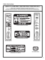
SAFETY, CONTROL, AND INSTRUCTION DECALS
Safety, Control, and Instruction Decals are installed on the machine;
if any are missing, illegible, or damaged, a replacement should be ordered and installed before
putting the machine into operation. The Decal Part Number is listed below and in the Parts Section.
Each End of Mower Deck (5808)
SD Deck Discharge Shield (5848)
LH Fender (5802-2)
RH Fender (5802-1)
Rear Body,
Above Muffler (5805)
Deck Gearbox Cover (5807-3)
15
Safety Instructions
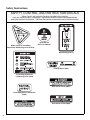
SAFETY, CONTROL, AND INSTRUCTION DECALS
Safety, Control, and Instruction Decals are installed on the machine;
if any are missing, illegible, or damaged, a replacement should be ordered and installed before
putting the machine into operation. The Decal Part Number is listed below and in the Parts Section.
Blade Clutch on Front Body
Adjacent to RH Steering Lever (4107-6)
Hydrostat Oil
Reservoir (4024-2)
Belt Routing (4107-5)
Parking Brake (7809)
Front Body Adjacent to
LH Steering Lever (7818)
Deck Carrier Frame (8647)
Center Body Behind Transaxles
(9804)
Deck Carrier Frame (5865)
Deck Carrier Frame (8653)
16
Assembly Instructions
SETUP INSTRUCTIONS
Walker Mowers are shipped partially assembled to
our distribution network, and are typically assembled
by the selling dealer. For any additional assembly
besides the following, contact your Walker dealer.
Battery Service
The battery is a completely sealed, non serviceable
battery.
IMPORTANT: Make sure battery is securely
mounted in the frame. A loose battery may cause
damage to the case resulting in acid leakage and severe damage to the machine. A hazard may be created by damage to critical working parts and safety
systems.
Mower Deck Assembly
Deck Caster Wheels Installation
1.
Remove the bolt, nut, axle spacer tube, and
spacer washers from each deck caster wheel
fork.
NOTE: Spacer washers are used only when
the optional semi-pneumatic deck wheels (8.25
x 2.75) are installed.
2.
Fit the axle spacer tube through the wheel hub,
position the spacer washer on each side of the
hub (if used), and fit the assembly into the wheel
fork.
3.
Insert the 3/8-16 x 4-1/2 in. bolt through the
wheel fork with the bolt head to the outside and
install the 3/8-16 in. Keps nut.
4.
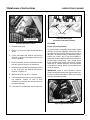
Deck Caster Wheel Installation
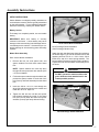
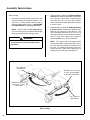
Deck Discharge Shield Installation
(Side Discharge Models Only)
Attach the deck side discharge shield by positioning
the shield hinge lug in front of the deck mount and
fastening with two 3/8-16 x 1-1/4 in. bolts, 3/8-16
ESNA nuts, and 3/8 in. wave spring washers. The
wave washers fit between the two hinging surfaces.
Tighten the nuts until the shield moves freely but is
not loose.
WARNING
DO NOT operate the machine without the
grass deflector chute attached and in the
lowest possible position.
Attach Shield
Tighten the bolt and nut until the axle spacer
tube bottoms against the inside of the wheel
fork (will not turn) while the wheel and spacer
washers (if used) spin freely without binding.
Deck Discharge Shield Installation
17
Assembly Instructions
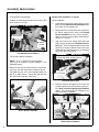
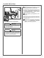
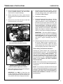
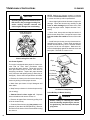
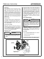
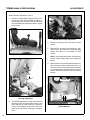
PTO Shaft Guard Installation
Mower Deck Installation on Tractor
Position the shaft guard as shown and mount with
two 1/4-20 x 1/2 in. bolts.
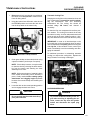
Deck Installation
1.
Lightly grease each deck support arm (2) on the
tractor. Refer to Mower Deck Installation photo
for location of deck support arm.
2.
Engage the deck carrier frame tube sockets on
the tractor support arms (refer to PTO Shaft
Guard Installation photo for socket location).
Slide the deck onto the support arms approximately 3 in. (76 mm).
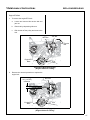
3.
Align and connect the splined PTO shaft and
socket halves, as shown in PTO Shaft Connection photo. The PTO shaft has a pilot end to ease
alignment of shaft; fit shaft end into socket and
rotate shaft until the splines line up as indicated
by arrows, then slide together.
Carrier Frame
Tube Sockets
Attach
Guard
PTO Shaft Guard Installation
Arrows on Shaft and Tube
(used to align when sliding together)
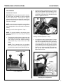
Tilt-Up Roller Wheel Installation
NOTE: A 2-1/2" diameter tilt-up roller wheel
(P/N 9772) is required for decks installed on the
Model MB tractor.
Mount the two (2) tilt-up roller wheels on the brackets on the rear skirt of the deck housing using the
P/N 8490 axle bolt, 3/8 in. wave spring washer and
3/8-16 in. Whiz locknut. Tighten the axle bolt until
the wheel rolls freely, but is not loose.
PTO
Connection
PTO Shaft Connection
4.
Install the hitch pin through the hole on the end
of each support arm to lock the deck in place (refer to Deck Counterweight Spring Installation
photo). Two (2) hitch pins are included in the
owner's packet of materials.
Roller Wheels
Roller Wheel Installation
Deck Support
Arms
Mower Deck Installation
18
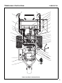
Assembly Instructions
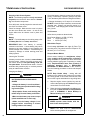
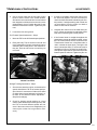
Spring Tension Adjustment Nut
Located Under Lower
Spring Hook (not visible)
Counterweight Springs
Clip Onto Body
With Body Tilted Up
5.
Raise mower body (instead of lifting the front of
deck) and clip the counterweight springs to the
receptacle on front of body. Lower the body to
tension the springs. (Refer to Deck Counterweight Spring Installation photo.)
6.
With the counterweight springs connected, the
weight on the deck caster wheels should be 15
to 25 Ib (6.8 to 11.3 kg). Check this weight by lifting on the front of the deck carrier frame. If
required, the spring tension can be adjusted by
tightening or loosening the elastic stop nuts located underneath the lower spring hook. Refer
to Deck Counterweight Spring Installation
photo.
Hitch Pins
Lock Deck On
Support Arms
Deck Counterweight Spring Installation
19
Assembly Instructions
Deck Leveling
1.
2.
Check the side-to-side level. Rotate each blade
sideways and measure the distance from blade
tip to ground on each side. If measurements
vary more than 1/8 in. (3 mm), add a washer
shim under the deck support pins on the low side
to level the deck.
3.
Check the front-to-rear level. Rotate the blades
to point forward. Measure the distance from
blade tip to ground on the front and rear. The
rear of the blade should be 1/8 to 1/4 in. (3 to 6
mm) higher than the front of the blade; shim the
rear (or front) deck support pins equally to
achieve at least 1/8 in. (3 mm) difference.
Position mower on a smooth, level surface. Set
the cutting height to the highest position - 4 in.
(102 mm) - for easy access under the deck to
measure blade height. Refer to ADJUSTING
CUTTING HEIGHT in Operating Instructions.
NOTE: A block of wood cut 4 in. (102 mm) high
is a convenient gauge to measure blade height
above ground during the leveling process.
WARNING
NOTE: The mower deck and support frame
are jig welded; within normal tolerances, very little, if any, shimming should be required to level
the deck. Tire pressure will influence the levelness of the deck. Check the tire pressure as a
possible cause of the deck not being level.
The machine must be shut off during this
procedure.
4 in. (102 mm)
Wood Block
Should be 1/8 in. (3 mm)
to 1/4 in. (6 mm) higher
at the rear of the blade
Should not vary more
than 1/8 in. (3 mm)
side-to-side
4 in. (102 mm)
Wood Block
Deck Leveling
20
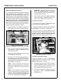
Assembly Instructions
PREOPERATING CHECKLIST
Before operating the mower for the first time, and as
a routine before daily operations, it is important to
make sure the mower is properly prepared and ready
for operation. The following is a list of items to be
checked. (For a mower with frequent operation,
some of these items will not need to be checked every
day, but the operator should be aware of the condition
of each.)
Body Rod
Body Rod
Body Rod in Stowed Position
CHECK BODY ROD IN STOWED POSITION
Check that body rod is secured in the stowed position
before lowering body. Refer to Body Rod in Stowed
Position photo.
For proper fuel and lubricants refer to Specifications.
Body Rod in Engaged Position
FILL FUEL TANK
Fill the fuel tank using clean, fresh, automotive grade
unleaded gasoline (85 octane rating minimum).
21
Assembly Instructions
DANGER
Handle gasoline with care. Gasoline is highly flammable and its vapors are explosive.
Use safe refueling procedures:
• DO NOT fill fuel tank with the engine running.
• If the engine is hot, allow to cool before
refueling.
• Use an approved fuel container.
• Fuel the mower outdoors.
• DO NOT smoke while refueling.
• Avoid spilling fuel; use a funnel or spout.
• DO NOT overfill the fuel tank; fill up to
about 1 in. (25 mm) below the top of tank.
IMPORTANT: DO NOT permit dirt or other foreign
matter to enter the fuel tank. Wipe dirt from around
the filler cap before removing. Use a clean fuel storage container and funnel.
IMPORTANT: DO NOT mix oil with gasoline.
Always use fresh, automotive grade unleaded gasoline. DO NOT use premium, white, or high-test
gasoline. DO NOT use additives, such as carburetor
cleaners, deicers, or moisture removing agents. DO
NOT use gasoline blended with methyl alcohol.
CHECK ENGINE COOLING SYSTEM
Check that the engine cooling air intake screen is free
of obstruction by grass clippings or debris and clean
if required. Also, cylinder head cooling fins should be
inspected and cleaned if any build-up of debris is
noted. Contact your Walker Dealer to perform this
procedure.
CHECK SECURITY OF DRIVE TIRE MOUNTING NUTS
The eight (8) Drive Tire mounting nuts should each
be torqued to 75-85 ft-lbs. (101.7-115.2 N⋅m).
INSPECT TWO (2) DRIVE BELTS
Engine/PTO and Ground Drive.
CHECK HYDROSTATIC TRANSAXLE OIL
LEVEL
Refer to LUBRICATION for Transaxle Lubrication
in Maintenance Instructions.
CHECK TIRE PRESSURE
Deck Caster Wheel = 20 PSI (137 kPa)
Drive = 15 PSI (103 kPa)
Rear = 20 PSI (137 kPa)
CHECK AND CLEAN GRASS
UNDERNEATH MOWER DECK
BUILDUP
Refer to CLEANING in Maintenance Instructions for
deck cleaning information.
CHECK ENGINE CRANKCASE OIL LEVEL
Check the engine crankcase oil level before use and
after each 8 hours of continuous operation. Refer
to LUBRICATION for Checking Engine Crankcase
Oil Level in Maintenance Instructions.
CHECK AND SERVICE ENGINE AIR CLEANER SYSTEM
• Check condition, cleanliness, and security of the
complete air filter element (clean air filter every
100 hours). For detailed procedures, refer to
CLEANING the Air Cleaner System in Maintenance Instructions.
22
DANGER
Never operate cutter blades with deck in
raised position because it is hazardous.
The tilt-up deck can be secured in the raised position
by unlocking the deck lock levers on each side of the
carrier frame and inserting the deck hook into the tiltup latch on the tractor body. Before operating the
tractor, make sure to re-engage the deck lock levers
after lowering the deck to the normal operating position.
Assembly Instructions
CHECK MOWER BLADE CONDITION, SHARPNESS, AND SECURITY OF MOUNTING
The blade mounting nut should be tightened to 60 ftlb (81.3 N⋅m). If blade sharpening is required, refer
to CHECKING/SERVICING for Sharpen Mower
Blades in Maintenance Instructions.
ADJUST MOWER CUTTING HEIGHT, IF REQUIRED
Tilt-Up Latch
Deck Secured in Tilt-Up Position
Position the hitch pins in the four deck support pins.
Refer to the “Cutting Height Adjustment” decal on the
deck gearbox cover.
PERFORM ANY ADDITIONAL PROCEDURES
called for on the MAINTENANCE SCHEDULE
CHART in Maintenance Instructions.
CAUTION
Do not operate machine with deck tilt-up
pivot joint unlocked.
DANGER
Do not operate the mower with deck in tiltup position. Do not move the tractor with
the deck in the tilt-up position.
23
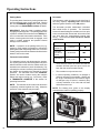
Operating Instructions
CONTROL IDENTIFICATION, LOCATION, AND
FUNCTION
seconds. If the engine does not start, return the key
to the “O” position for at least 60 seconds before
making a restart attempt. Prolonged cranking can
damage the starter motor and shorten battery life.
Release the key when the engine starts, and it will
return to the RUN position. To stop the engine, rotate
the key counterclockwise to the “O” position.
CAUTION
Before operating the mower, become familiar with the location and function of all
operator controls. Knowing the location,
function, and operation of these controls
is important for safe and efficient operation of the mower.
OFF
ON
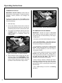
Ignition Switch
The ignition switch is located on the right front of the
body and is used to start and stop the engine. The
switch has three positions: “O” is the OFF position,
RUN is the position the key returns to after starting,
and “S” is the START position. When starting the
engine, turn the key clockwise to the “S” position. Do
not hold the key in the “S” position longer than 10
START
Ignition Switch
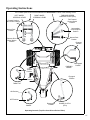
Parking Brake
Forward Speed
Control (FSC)
Steering
Levers
Choke
(not visible)
Blade Clutch
(PTO)
Throttle
Body
Latch
Ignition
Switch
Hourmeter
Operating Controls
24
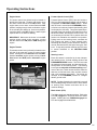
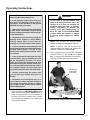
Operating Instructions
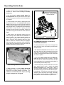
Engine Choke
Forward Speed Control (FSC)
The choke control lever (black knob) is located on
the left side of the seat. To start a cold engine, move
the choke control forward to the ON position. After
engine starts, move choke control toward the OFF
position, keeping enough choke to allow the engine
to run smoothly as it warms up. As soon as possible,
move the choke to the OFF position. A warm engine
requires little or no choke for starting.
Forward Speed Control (FSC) has two functions:
One is to set forward travel speed, and the other is
to establish the NEUTRAL-PARK position. When
the FSC lever is moved into the FORWARD position,
a friction lock holds any forward speed setting from
0 to 8 mph (0 to 12.9 km/h). The ground speed is proportional to the lever position; the further the lever is
advanced forward, the faster the tractor moves. It is
not necessary to hold the FSC in position since the
friction lock maintains the selected lever position.
Pulling back on the steering levers overrides the
FSC setting and slows or stops forward travel.
Releasing the steering levers allows the tractor to
resume forward travel at the speed set by the FSC
lever. To stop and park the machine, the FSC lever
is moved backward to the NEUTRAL-PARK
position.
IMPORTANT: Make sure the choke is in the OFF
position during normal engine operation; running
with the choke in the ON position CAN damage the
engine.
Engine Throttle
The throttle control lever (red knob) is located on the
left side of the seat and is used to control engine
speed. Moving the lever forward toward the FAST
position increases engine speed; moving it backward toward the IDLE position decreases engine
speed.
Throttle
Choke
Steering Levers
Each drive wheel is controlled by its own independent steering lever, for both steering function and
FORWARD/REVERSE motion. The FSC lever sets
the maximum forward speed, and also sets the forward position of the steering levers. The steering
levers operate only with a backward pulling movement of the lever, which causes the drive wheel for
that lever to first slow down, stop, and then reverse
with a full backward lever stroke. The levers are
released to the FORWARD position for “straightahead” ground travel.
NOTE: Pushing forward on the steering levers will
not cause any change in tractor motion - there will be
no steering lever reaction and there will be no
machine damage.
Choke and Throttle Location
Blade Clutch (PTO)
The blade clutch lever has two positions. Pulling the
lever UP engages the PTO that drives the mower
blades. Pushing the lever DOWN disengages the
PTO and engages the blade brake.
25
Operating Instructions
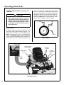
Parking Brake
Hourmeter
The parking brake functions by locking a detent arm
into the transaxle outer control gear teeth. Moving
the lever FORWARD engages the parking brake;
moving the lever BACKWARD releases the brake.
The hourmeter, which is located on the right front of
the body, displays operating time accumulated
while the ignition switch is in the ON position.
IMPORTANT: Stop the tractor completely before
engaging the parking brake. The parking brake uses
a positive mechanical lock similar to the PARK position on an automotive automatic transmission. If the
tractor is moving when the brake is engaged, it will
result in sudden stoppage and possible internal
damage to the transaxle.
The hourmeter provides maintenance reminders
after certain hours of operation. The hourmeter
screen will start flashing the reminder one hour prior
to the recommended interval and will continue until
one hour after the recommended interval (two
hours). The hourmeter does not have a manual
reset function.
Procedure
Interval*
NOTE: If pressure on the parking brake pin (e.g.
parked on a hill) makes it impossible to release the
parking brake with the parking brake lever, move the
mower gently forward or backward to allow the brake
detent to set into the teeth.
Oil Change
(Break-In)**
4-6 Hours
Lubricate
and Check
Levels
24-26 Hours
Transaxle Lockout Rods
Oil Change
The transaxle lockout rods disengage the transaxles. By lifting the rods up and locking them into place
with the shoulder on the rod in the chassis notch, the
transaxles are released to permit freewheeling. By
releasing the rods and recessing them back toward
the chassis, the transaxles are engaged for normal
operation. The transaxle rods in the LOCKOUT
position are used to enable moving the machine
without the engine running (e.g., for service). Refer
to TRANSAXLE LOCKOUTS in this section for
operating instructions.
NOTE: The transaxle lockout rods ends should be
completely retracted against the body, otherwise
operation of the transaxle may be erratic.
49-51 Hours***
C
H
G
0*-6#&
C
H
G
0*-
*
These intervals reflect the actual time that the
reminder will flash (one hour prior to and one
hour after the recommended interval).
**
This reminder is only used one time.
*** In normal operating conditions, oil changes in
100-hour intervals are acceptable. Walker and
the engine manufacturers recommend engine
oil changes every 50 hours in extremely dirty
or dusty conditions or for units with less than
100 hours annual use.
NOTE: The blinking hour glass on the display
means that the meter is operating properly.
Hydro Lockout
Rods
Hydro Lockout Rod Location
Hourmeter
26
Reminder
Operating Instructions
The Forward Speed Control also Establishes the Neutral-Park Position of the Steering Levers
LEFT WHEEL
STEERING LEVER
FORWARD SPEED
CONTROL LEVER (FSC)
RIGHT WHEEL
STEERING LEVER
Full Forward
Ground Speed
Position
Forward Position
(No Control Change)
Intermediate
Ground Speed
Position
Neutral-Park
Position
Neutral-Park
Position
Reverse Drive
Wheel Motion
Position
Engaged
Position
PARKING
BRAKE
Fast
Throttle
Position
Disengaged
Position
Engaged
Position
Idle
Position
THROTTLE
ON Position
OFF Position
CHOKE
Disengaged
Position
BLADE CLUTCH
(PTO)
Operating Controls (Top View from Drivers Point of View)
27
Operating Instructions
STARTING THE ENGINE
IMPORTANT: DO NOT crank the engine continuously for more than 10 seconds at a time. If
the engine does not start, turn the key to the
OFF position and allow a 60 second cool-down
period between starting attempts. Failure to follow these guidelines can damage the starter
motor and shorten battery life.
CAUTION
Before operating the mower, read and understand all Safety Instructions and Operating Instructions.
3.
WARNING
NEVER run the engine in an enclosed or
poorly ventilated area. Engine exhaust
contains carbon monoxide, an odorless
and deadly gas.
1.
Before attempting to start the engine, make
sure the operator is in the seat, the Forward
Speed Control is in NEUTRAL-PARK position,
and the blade clutch and parking brake are
DISENGAGED.
NOTE: Release parking brake to prevent extra
load on the starter if the transmission neutral is
slightly out of adjustment.
CAUTION
A safety interlock switch system PREVENTS CRANKING the engine with either
the Forward Speed Control or the blade
clutch (PTO) out of neutral. If the engine
cranks otherwise, the safety system is not
working and should be repaired or adjusted before operating the mower. DO NOT
disconnect safety switches; they are for
the operator's protection.
2.
Move the choke lever to the ON position and
move the throttle 1/4 to 1/2 open (toward FAST).
Turn the ignition switch to the START position to
start the engine. Release the key to RUN position as soon as the engine starts.
NOTE: The choke may not be required if the
engine is warm.
28
After the engine starts, gradually move the
choke to the OFF position, keeping enough
choke on to allow the engine to run smoothly as
it warms up. As soon as possible, move the
choke to the OFF position.
IMPORTANT: Make sure the choke is in the
OFF position during normal engine operation;
running with the choke in the ON position CAN
damage the engine.
ADJUSTING GROUND SPEED AND STEERING
CAUTION
Learn to START, STOP, and MANEUVER
the mower in a large, open area.
If the operator has not operated a machine
with LEVER STEERING OR DUAL TRANSAXLES, steering and ground operation
should be learned and practiced until the
operator is completely comfortable handling the machine BEFORE ATTEMPTING
TO MOW.
DANGER
Keep feet on footrest at all times when the
machine is moving.
Operating Instructions
WARNING
Beginning Recommendations are:
♦ Learn operation of the mower in an open
area away from buildings, fences, and obstructions. Learn operation on flat ground
BEFORE operating on slopes.
In case either of the transmission drive
belts break during operation, and if the
machine is on a slope, the machine will
freewheel down the slope. To maintain
control, immediately (1) Release the
steering levers and simultaneously (2)
Move the FSC to the NEUTRAL-PARK
position. When the machine is stopped
or moving slowly, engage the parking
brake.
♦ Start maneuvering the mower with SLOW
engine speed and SLOW Forward Speed
Control setting until familiar with all operating characteristics.
♦ Remember it is not necessary to hold the
steering levers forward (a unique Walker
feature); always PULL on the levers for
steering or for reverse motion of the mower.
♦ Learn to operate the mower with your left
hand on the steering levers and right hand on
Forward Speed Control. The use of two
hands on the steering levers tends to cause
overcontrol.
♦ Learn to operate the steering levers with
smooth action. Jerky movements are hard
on the transmission and lawn. For sharp
turns, do not allow the inside wheel to stop
and twist on the grass. Pull the steering lever controlling the inside wheel into reverse
for a smooth “rolling” turn (one wheel rolling forward while the other rolls backward).
NOTE: This is exactly the same procedure
used to normally stop and park the machine.
NOTE: If the FSC lever will not stay in the
selected position, the friction lock needs to be
adjusted. Contact your Walker Dealer.
2.
Steer by pulling the lever on the side of desired
direction of turn, e.g., pull the LH lever to turn
left. To minimize the possibility of overcontrol,
use only one hand on both steering levers.
Pull Steering
Levers with
Left Hand
♦ Practice maneuvering the mower until
you can make it go exactly where you are
aiming.
♦ Remember, for an emergency stop, or in
case of loss of control, machine movement
can always be stopped quickly by pulling
the Forward Speed Control into the NEUTRAL-PARK position.
1.
Move the FSC out of NEUTRAL-PARK position
to the desired forward speed. DO NOT hold forward on steering levers. It is not necessary to
hold the FSC lever in position since a friction
lock maintains the selected lever position (and
forward travel speed).
Forward Speed Control
(FSC)
Keep Feet on Footrest
when Moving
Correct Operator Hand Position on the Controls
29
Operating Instructions
3.
Reverse direction of the mower by pulling both
levers backward.
NOTE: Smooth action on the steering levers
will produce smooth mower operation. Remember to keep the engine and ground speed slow
until learning the control response.
4.
The FSC may be adjusted forward for faster
ground speed and backward for slower ground
speed. When mowing, ground speed should be
adjusted to match the load on the cutter blades,
i.e., as the engine pulls down in heavy cutting,
pull back on the FSC lever to reduce ground
speed. Adjusting ground speed helps maintain
a balance between engine power and blade
speed for high-quality cutting action.
5.
Stop ground travel by pulling both steering
levers backward to the NEUTRAL-PARK position (tractor not moving) and then moving the
FSC lever to the NEUTRAL-PARK position.
NOTE: If the tractor creeps forward or backward with the FSC lever in the NEUTRAL-PARK
position, the transmission control needs to be
adjusted. Contact your Walker Dealer.
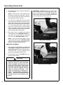
IMPORTANT: DO NOT engage the blade clutch
when transporting the mower across drives, sidewalks, loose materials, etc. DO NOT engage the
blade clutch with the PTO shaft disconnected
(the mower deck removed from tractor).
Blade Clutch Engaged
ENGAGING THE MOWER
1.
Set the engine throttle at about 1/3 speed. Do
not attempt to engage the blade clutch at
high engine speeds. This will drastically shorten drive belt life. Use only moderate engine
speed when engaging the blade clutch.
2.
Pull the blade clutch lever SLOWLY up to engage the mower blades.
CAUTION
A safety interlock switch (seat switch) will
cause the engine to stop if the blade
clutch is engaged and the operator is not
in the seat. The function of this switch
should be checked by the operator raising off the seat and engaging the blade
clutch; the engine should stop. If the
switch is not working, it should be repaired or replaced before operating the
mower. DO NOT disconnect the safety
switches; they are for the operator's protection.
30
Blade Clutch Disengaged
Operating Instructions
CAUTION
If the cutting blades strike a stationary
object while mowing, stop the mower immediately, disconnect the spark plug
wires, lift the deck, and inspect the deck
and blades thoroughly for damage. Make
sure that the blade timing has not been disturbed (the blades should be at 90 degrees
to each other). Refer to REPLACING/REPAIRING the Blade Overload Shear Bolts
in Maintenance Instructions if blades are out
of time. Also, make sure the blade retaining nuts are torqued to 60 ft-lb (81.3 N⋅m).
STOPPING THE MACHINE
1.
Slow the engine to idle; put the throttle in the
IDLE position.
2.
Pull the steering levers to the NEUTRAL-PARK
position and then move the FSC lever backward
to the NEUTRAL-PARK position.
3.
Disengage the blade clutch.
IMPORTANT: DO NOT disengage the blade
clutch with high engine speed (above 1/2
throttle) since the brake action on the blade drive
will cause premature wear of the Engine/PTO
Belt and internal braking mechanism (or
system).
5.
Engage the parking brake.
IMPORTANT: The transaxles lock to prevent the
mower from rolling freely with the engine
stopped. However, if the mower is parked on a
slope, it is necessary to ENGAGE the parking
BRAKE to prevent the mower from creeping.
This is due to a small amount of slippage in the
transaxles, especially when transmission fluid
is warm.
ADJUSTING CUTTING HEIGHT
WARNING
The engine must be stopped before adjusting cutting height. Disengage the
blade clutch (PTO), stop the engine, and
remove the ignition key. Wait for all movement to stop before getting off the seat.
Cutting height is adjusted by positioning the four
retainer hitch pins in a series of seven vertical
holes on the deck support pins. Lift handles have
been provided on each end of the deck to assist in
raising the deck while positioning the hitch pins. Cutting heights range from 1 in. (25 mm) [top holes] to
4 in. (102 mm) [bottom holes] in 1/2 in. (13 mm)
increments.
Lift Handle
WARNING
A brake stops the cutter blades from freewheeling within five (5) seconds after disengaging the clutch. If the brake system
malfunctions and the blades do not stop
within five (5) seconds, the brake should
be repaired or replaced before operating
the mower. Contact your Walker Dealer.
Deck Support Pin
Hitch Pin
4.
Turn the ignition switch OFF.
WARNING
Cutting Height Adjustment
Remove the key from the ignition switch
when leaving the mower unattended. This
will prevent children and inexperienced
operators from starting the engine.
31
Operating Instructions
TRANSAXLE LOCKOUTS
IMPORTANT: DO NOT TOW this mower with the
transmission lockout engaged. Towing can produce
excessive internal pressure and damage the
transaxle.
Hydro Lockout Rod
To move the mower with the engine NOT running
(dead battery, maintenance, etc.), the transaxles are
unlocked (released).
1.
Raise the body.
2.
Pull up the transaxle lockout rods on both the
RH and LH transaxles and secure into place by
shouldering both rods in the chassis notch area.
3.
The mower will “freewheel” with the rods in the
LOCKOUT position. The levers must be in the
highest position to completely unlock the
transmissions.
Hydro Lockout Rod
Hydro Lockout Rod - Normal Operating Position
RECOMMENDATIONS FOR MOWING
IMPORTANT: Operate the engine at full speed
when mowing, to allow the engine to produce full
horsepower and to increase efficiency of the engine
cooling system.
• Keep the mower deck and discharge chute clean.
• Mow with sharp blades. A dull blade tears the
grass (resulting in poor lawn appearance) and uses
extra power (slowing the mowing speed).
• It is preferable to cut grass when it is dry and not
too tall. Mow frequently and do not cut grass too
short. (For best appearance, cut off 1/3 or less of
existing grass height.)
Hydro Lockout Rod - Freewheel Position
4.
After moving the mower, release the rods, placing them in the normal OPERATING position.
The transmission rod ends should be completely retracted against the chassis, otherwise
operation of the transmission maybe erratic.
• When mowing, operate the engine at or near full
throttle for the best cutting action. Mowing with a
lower engine RPM causes the mowing blade to not
cut clean and tear the grass. The engine is
designed to be operated at full speed.
• When mowing in adverse conditions (tall and/or
wet grass), mow the grass twice. Raise the mower
to the highest setting - 4 in. (102 mm) - for the first
pass and then make a second pass cutting to the
desired height.
• Use a slow setting on the FSC for trimming
operations.
32
Operating Instructions
• Make sure the mower is leveled properly for a
smooth cut. Refer to Deck Leveling in Assembly
Instructions.
• Use an alternating stripe mowing pattern for
best appearance and vary the direction of the stripe
each time the grass is mowed to avoid wear patterns
in the grass.
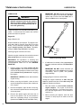
Maximum Recommended
Side Slope - Do Not Operate
on Steep Slopes
• Avoid damage to the grass by slipping and skidding of the drive tires. Use smooth control movements of the steering levers since the transaxles are
“power boosted controls” and jerking the levers can
easily slip the tires. For sharp turns, do not allow the
inside wheel to stop and twist on grass; pull inside
steering lever into reverse for a smooth “rolling” turn
(one wheel rolling forward while the other rolls backward).
• When using a side discharge mower deck, the
side discharge shield must not be removed and
must be kept in the lowest possible position to
deflect grass clippings and thrown objects downward. Orient the side discharge away from sidewalks or streets to minimize cleanup of clippings.
When mowing close to obstacles, orient the side discharge away from obstacles to reduce the chance of
damage to property by thrown objects.
Discharge
Shield
20°
22 in.
60 in.
Maximum Recommended Side Slope
RECOMMENDATIONS FOR TILT-UP DECK
OPERATION/TRANSPORT
To avoid potential deck and/or tractor damage while
using the tilt-up deck, the following recommendations are offered:
• Do not move the tractor with the deck in the tiltup position since both the roller wheels (on the back
of the deck) may be damaged by moving the tractor.
The tilt-up configuration should only be used when
the tractor is parked.
• The tractor body should never be tilted forward with the deck in the tilt-up position. This can
cause the deck to unhook from the tractor and fall
with considerable force, potentially causing deck or
tractor damage and/or bodily injury.
Side Discharge Shield in Lowest Position
• When operating on a slope, reduce speed and
use caution to start, stop, and maneuver. Avoid
sharp turns or sudden changes in direction. The
maximum recommended side slope operating
angle is 20 degrees or 33% grade.
• When transporting a tractor with the deck in the
tilt-up position (on a truck or trailer), the deck
should be secured to the vehicle with a strap or
rope (stop vertical movement). This will prevent the
deck from bouncing on the rear roller wheels (causing breakage). This will also prevent the deck from
unhooking from the tractor and falling, potentially
causing deck or tractor damage. Damage to other
items parked in front of the deck may also occur.
33
CAUTION
Maintenance Instructions
Maintenance procedures requiring special training or
tools should be performed by a trained technician.
MAINTENANCE SCHEDULE CHART - RECOMMENDED SERVICE INTERVALS - MODEL MB
Service Item
Daily
25
Hours
50
Hours
100
Hours
250
Hours
Ref.
Page
Check Engine Crankcase Oil Level
x
36
Check/Clean Engine Air Cooling System*
x
41
Clean Grass Buildup Under Deck
x
42
Service Mower Blades
x
44
Check Security of Air Cleaner System
x
44
Lubricate Grease Fittings and Oil Points*
x
37
Check Transaxle Fluid
x
40
Check Tire Pressure
x
44
Check Drive Belts (Engine/PTO, Ground Drive)
x
45
Check PTO and Deck Gearbox Oil Seals
x
45
Inspect Air Filter Paper Element*
x
42
Clean and Re-Oil Air Filter Foam Element
x
42
Change Engine Crankcase Oil**
x
36
Change Engine Oil Filter
x
36
Check Security of Drive Tire
Mounting Nuts (75-85 ft-lbs.)
x
22
Clean Transaxle Cooling Fins
x
43
Change Transaxle Oil and Filter
x
∗
∗∗
More often in extremely dusty or dirty conditions
(see notes about air cleaner element under
IMPORTANT TIPS FOR CARE OF
BRIGGS & STRATTON ENGINE)
Change engine oil and filter after first 8 hours
of operation of a new engine (break-in period)
40
x
Replace Fuel Filter
34
Yearly
49
CAUTION
When performing maintenance with the
mower body raised, a safety prop should
be installed from back of body to chassis
frame (fail-safe protection in case of failure of body lift support).
Maintenance Instructions
IMPORTANT TIPS FOR CARE OF THE
BRIGGS & STRATTON ENGINE
Fuel System
• Fuel must be clean - free from water, dirt, and organic material.
• Clean the fuel filter on a regular basis and when
contamination is suspected or found in the fuel.
Starting
• Start engine with the throttle advanced off idle
(1/4 to 1/2 throttle). This will aid starting, especially
in cold weather.
• Keep the battery fully charged.
• Match crankcase oil viscosity to the ambient temperature, allowing the engine to crank faster and
start easier.
• Allow engine to run at idle for a few seconds before stopping engine to avoid run-on or backfiring.
Cooling System
• Keep engine air intake screen and cylinder head
fins free of grass clippings, chaff, and dirt. Inspect
intake screen and cooling fins for cleanliness and
damage.
• Operate the engine at full speed when mowing.
This will allow the engine to produce full horsepower
and move more cooling air through the engine cooling fins.
BRIGGS & STRATTON TIPS
Air Cleaner
• Use only Briggs & Stratton air cleaner elements.
Aftermarket elements may not seal in the air cleaner
housing, allowing dirt to enter the engine. Also, aftermarket filters often skimp on the filtration media
and require more frequent cleaning and replacement.
• DO NOT overservice or frequently “disturb” the
air filter. A dirty air filter actually cleans better than
a new one. Changing and cleaning the filter too often can actually reduce filter efficiency and increase
the opportunity for traces of dust to enter the engine.
Wait until the element really needs servicing as indicated by the loss of engine power.
• When the air filter element is removed or replaced, make sure all dust is cleaned out of the air
cleaner body. Use a damp cloth and wipe the interior of the air cleaner body clean (a little dirt left here
will be sucked into the engine and reduce engine
life). When the filter is reinstalled, make sure the element is held tight and straight in the air cleaner
body for proper seating and sealing.
Oil
• Single viscosity or multi-viscosity oils may be
used with the viscosity matching ambient temperatures for the engine operating conditions. This will
aid starting in cold weather and assure proper lubrication in hot weather.
• Use only Briggs & Stratton oil filters. Aftermarket
filters may not seal properly and/or have the incorrect pressure relief valve for proper lubrication.
35
Maintenance Instructions
LUBRICATION
LUBRICATION
IMPORTANT: DO NOT operate engine without
sufficient oil supply in the crankcase. DO NOT
operate with oil level below the LOW mark or
above the FULL mark on the dipstick.
WARNING
DO NOT attempt to lubricate the machine
with the engine running. Disengage the
PTO clutch, shut off the machine, and remove the ignition key.
Proper lubrication is an important maintenance procedure. It reduces wear and makes the machine
quieter and easier to operate.
Engine Oil
Engine Break-In Oil
No special break-in oil is required. The engine is serviced with 10W-30, Service Class SG oil from the
factory. The oil should be changed after the initial
engine break-in period of 5-8 hours. Thereafter,
change oil after every 50 hours of operation.
Operating
Range
{
Checking Engine Crankcase Oil Level
Check the engine crankcase oil level before use and
after each 8 hours of continuous operation.
FULL
Mark
LOW
Mark
Dipstick Operating Range
IMPORTANT: The importance of checking and
maintaining the proper crankcase oil level cannot be
overemphasized. Check the oil level BEFORE
EACH USE.
1.
Park the mower on a level surface with the
engine stopped. Also, make sure the engine is
cool and oil has had time to drain into the sump
[allow at least five (5) minutes after stopping
the engine].
IMPORTANT: NEVER check or add oil with the
engine running.
2.
36
5.
Before removing the dipstick, clean the area
around the dipstick to keep any dirt or debris out
of the engine.
3.
Remove the dipstick, wipe off with a clean rag,
then reinsert the dipstick into the tube and press
all the way down.
4.
Remove the dipstick again and check the oil
level on the dipstick. The oil level should be
within the “Operating Range” on the dipstick
(between the LOW mark and the FULL mark).
If additional oil is needed, refer to Specifications
for proper crankcase lubricant. Fill to the FULL
mark.
IMPORTANT: DO NOT overfill crankcase [oil
above FULL level] as this CAN result in engine
overheating, loss of power, and possible
engine damage.
Changing Engine Crankcase Oil/Oil Filter
Change the engine crankcase oil after every 50
hours of operation and the oil filter after every 100
hours of operation as follows:
1.
Park the mower on a level surface with the
engine stopped. The engine oil should be
warm before draining. If not warm from operation, start the engine and run a few minutes to
warm the oil.
2.
Before removing the dipstick, clean the area
around it to keep any dirt or debris out of the
engine.
Maintenance Instructions
3.
Remove the dipstick and oil drain plug, and drain
oil into a suitable container. Be sure to allow
ample time for complete drainage.
4.
Before removing the oil filter, clean the area
around the filter to keep dirt and debris out of the
engine.
5.
Remove the old oil filter and wipe off the filter
mounting surface on the engine.
Oil Fill
Dipstick
Dipstick and Oil Fill
(view from above left side of tractor)
LUBRICATION
7.
Install the new oil filter on the engine. Turn the
oil filter clockwise until the rubber gasket contacts the sealing surface, then tighten the filter
an additional 1/2 to 3/4 turn.
8.
Reinstall the drain plug.
9.
Fill the crankcase with new, clean oil. Use only
crankcase lubricants recommended by the
engine manufacturer. Refer to Specifications in
this manual or the engine owner’s manual. Use
the recommended oil viscosity for the expected
ambient temperature. Oil with the correct viscosity will aid starting in cold weather and assure
proper lubrication in hot weather. Fill to FULL
mark on the dipstick; crankcase capacity is 1.5
quarts (1.4 liters) when changing oil and filter.
IMPORTANT: Check the dipstick reading before pouring in the last 1/2 pint of oil and fill only
to the FULL mark. The oil level should never be
over the FULL mark on the dipstick; overfilling
can result in engine overheating and loss of
power.
10. Start the engine and check for oil leaks around
the oil filter. Stop the engine, recheck the oil level, and add oil if necessary. (When the engine
is first operated with a new oil filter, the oil level
will drop slightly as the filter is filled with oil.)
Grease Fitting and Oil Point Lubrication
Lubricate the grease fittings and oil points after
every 25 hours of operation. Lubricate more often
when operating in dusty or dirty conditions. Use
SAE general purpose lithium or molybdenum base
grease for grease fittings and light machine oil (SAE
10) to lubricate oil points. Lubricate the locations
shown in the Chassis and Deck Lubrication
Points illustration.
Oil Filter
Oil Drain
Oil Drain and Oil Filter Locations
(view from above right side of tractor)
6.
Apply a thin coating of new oil to the rubber gasket on the replacement oil filter.
IMPORTANT: Use ONLY oil filters from the
engine manufacturer. Aftermarket oil filters may
not seal properly and/or may not have the correct pressure relief valve for proper lubrication.
NOTE: PTO universal joints (on the deck and tractor) require routine lubrication after every 8 hours of
running time.
NOTE: The best way to lubricate the PTO tube half
of the universal joint assembly is to remove it from
the tractor. See instructions for removing and installing PTO quick coupler, refer to Deck Installation in
Mower Deck Installation on Tractor in the Assembly Instructions.
37
Maintenance Instructions
Ident
No.
38
Location
'HFN&DVWHU:KHHO)RUN3LYRW
'HFN&DVWHU:KHHO%HDULQJ
7HH*HDUER['HFN
%ODGH'ULYH*HDUER[
8QLYHUVDO-RLQW6KDIW$VVHPEO\
'HFN6XSSRUW$UP6RFNHW
3LYRW$VVHPEO\7LOW8S'HFN
6WHHULQJ/HYHU3LYRW
'HFNWR372&RXSOLQJ
*UHDVH6OLGH$UHD
8QLYHUVDO-RLQW7XEH$VVHPEO\
7UDQVD[OH2LO5HVHUYRLU
'HFN6XSSRUW$UP3LYRW
+\GUR,GOHU$UP3LYRW
3DUNLQJ%UDNH&OHYLV
)6&/HYHU3LYRW
%RG\/DWFK
3DUNLQJ%UDNH/HYHU
372&OXWFK/HYHU3LYRW
Lubrication
Type
LUBRICATION
No.
Places
*UHDVH
*UHDVH
2LO
2LO
*UHDVH
*UHDVH
*UHDVH
*UHDVH
*UHDVH
*UHDVH
2LO
*UHDVH
*UHDVH
2LO
*UHDVH
2LO
2LO
*UHDVH
Ident
No.
Location
372%HOW7LJKWHQHU3LYRW
7KURWWOH&RQWURO&DEOH(QGV
(QJLQH2LO)LOOHU
&KRNH&RQWURO&DEOH(QGV
&KRNH&RQWURO3LYRW
7KURWWOH&RQWURO3LYRW
Lubrication
Type
*UHDVH
2LO
2LO
2LO
2LO
2LO
No.
Places
*HDUER[HVDUHSHUPDQHQWO\OXEULFDWHGDQGVHDOHGUHTXLULQJ
QRVFKHGXOHGOXEULFDWLRQ2LOOHYHOVKRXOGEHFKHFNHGRQO\
ZKHQDQRLOOHDNLVQRWHG
*UHDVHHYHU\HLJKWKRXUV
5HIHUWR(QJLQH2LOORFDWHGRQSDJH 127( '6' 7LOW8S 'HFN LV VKRZQ IRU UHIHUHQFH )RU RWKHU
'HFN /XEULFDWLRQ 3RLQWV UHIHU WR 'HFN DQG &DUULHU
)UDPH,OOXVWUDWHG3DUWV0DQXDO
Maintenance Instructions
1
LUBRICATION
2
1
3
2
4
5
6
4
7
7
7
6
7
8
20 & 24
9
10
11
11
12
12
22 & 23
13
14
15
16
22
17
18
21
20
19
Chassis and Deck Lubrication Points
39
Maintenance Instructions
LUBRICATION
Mower Deck Gearbox Lubrication
The mower deck gearboxes (tee gearbox and blade
drive gearboxes) are connected as a unitized
assembly, and oil flows freely between them. The
gearboxes are permanently lubricated (oil filled) and
sealed requiring no scheduled lubrication. However,
the gearbox oil seals should be checked every 25
hours for indication of an oil leak; particularly the
lower seals on the blade drive gearboxes should be
inspected, since they operate in a dirty environment.
If an oil leak is noted, replace the oil seal and relubricate the gearbox assembly as follows:
1.
Remove gearbox cover (footrest). Deck orientation should be the normal operating position.
Blade Drive
Gearboxes
IMPORTANT: DO NOT overfill the deck gearboxes. The gearbox assembly is not vented,
and overfilling with oil will cause excessive pressure and result in oil leaks.
5.
Check condition of the cover gasket and replace
if worn or damaged. Reinstall gearbox cover
plates; torque screws to 24 in-lb (2.7 N·m).
Transaxle Lubrication
• The transaxle oil lubrication is SAE 20W-50 (API
Service Class SL or higher) engine oil.
• Inspect both transaxle cases and hoses after every 100 hours of operation for visible leaks.
• The fluid levels for each transaxle can be
checked visually by looking at the fluid levels in each
expansion reservoir. When the transaxles are cold,
the fluid level in the expansion reservoirs should be
between 1/4" and 1/2" (.64 cm and 1.27 cm).
Reservoir Cap
Tee
Gearbox
Hot Level
Mower Deck Gearboxes
(shown with gearbox cover removed for clarity)
2.
Clean the area around the individual gearbox
cover plates to prevent contaminants from
entering the gearcase.
3.
Remove the screws securing the cover plates
on the blade drive gearboxes.
4.
Check the level of lubricant in the gearboxes. If
the lubricant is low, add SAE E.P. (Extreme
Pressure) 80W-90 oil until the oil level is up to
(submerges) the horizontal shaft in the gearbox
(shaft parallel to cover plate).
NOTE: In case the gearboxes are completely
drained of oil, approximately 5 fl. oz. (15 cl) of oil
per gearbox is required to refill the gear drive
assembly.
NOTE: Since the gearboxes are connected as
a unit by connector tubes, it is necessary to add
oil slowly. Allow a few minutes after adding oil
for the oil to flow throughout the assembly and
the oil level to stabilize before reassembly.
40
Cold Level
Expansion Reservoir Location
Transaxle Oil and Filter Change
Change the transaxle oil after the initial break-in
period of 50 hours. Thereafter, change oil every
250 hours of operation as follows:
1.
Thoroughly clean the exterior of the transmission housing before servicing. Using a 1/4” hex
wrench, remove the plug on the underside of
each transaxle allowing the oil to drain.
2.
Remove and replace the oil filters using a 3/8”
hex wrench. (Refer to Transaxle Oil Filter
Location photo.)
Maintenance Instructions
LUBRICATION/CLEANING
Drain Plugs
Use 3/8" hex wrench
to remove filter
Transaxle Oil Filter Location
Transaxle Drain Plugs
(view from underside of tractor)
CLEANING
3.
Reinstall drain plugs.
Engine Air Cooling System
4.
Place 6” (15 cm) block under the left hand drive
wheel.
5.
Fill the transaxles with 20W-50 (API Service
Class SL or higher) oil through the reservoir. Fill
up to the opening.
6.
Remove the block from the left wheel and reattach the reservoir hoses to the transaxles.
7.
Both reservoirs should have a maximum oil level
of 1/4” (6.35 mm) with 20W-50 (API Service
Class SL or higher) oil.
To prevent engine overheating and possible engine
damage, clean grass clippings, chaff and dirt from
the rotating engine air intake screen every 8 hours of
operation. In certain mowing conditions (dry grass,
leaves, tree "cotton", etc.) it may be necessary to
check and clean this area several times each day to
prevent engine overheating. Also, visually check
inside cylinder head shroud and between cylinder
head fins for material packed in this area which
would prevent cooling airflow; remove shroud and
clean as required.
8.
Start and drive the unit for 1- 2 minutes.
9.
If the transaxles sound noisy or have poor steering response, recheck oil level in both
transaxles by removing the elbows (check oil
level at fill opening).
IMPORTANT: Yearly or every 100 hours, remove
engine cooling shroud and clean cylinder head cooling fins to prevent overheating. Make sure cooling
shroud is reinstalled properly.
10. If oil needs to be added refer back to steps 5-9.
Rotating Engine Screen
Keep Engine Screen Clean
41
Maintenance Instructions
CAUTION
Operating the engine with a blocked air intake screen, dirty or plugged cooling fins,
and/or cooling shrouds removed will
cause engine damage from overheating.
Clean these areas
of dirt and debris
CLEANING
NOTE: Washing the element in water or cleaning
solution is not recommended. Replace the element
if it does not clean up with compressed air.
• Use a bright light inside the element to inspect for
damage. Check the element very carefully for pin
holes or other damage that will allow dirt to leak
through the paper media. Replace element if necessary.
• Use a clean, damp cloth and wipe the interior of
the air cleaner body clean. Use special care to clean
both the inside and outside surfaces of the outlet
tube.
• Install foam pre-cleaner over dry element and reassemble onto engine. Tighten knob mounting air
cleaner element securely, 1/2 to 1 turn after contacting cover, but do not over-tighten. Make sure element is sealed tightly against the element cover and
base plate. Reinstall air cleaner cover.
Clean Cooling Fins and Fan
Air Cleaner System
The engine is equipped with a paper air cleaner element with an oiled foam pre-cleaner which
surrounds the paper element. Clean and re-oil the
foam pre-cleaner every 25 hours; more often in
dusty/dirty conditions. Inspect the paper element
every 100 hours and replace yearly (or when dirty or
damaged). Service the foam precleaner as follows:
• Remove air cleaner cover and remove foam precleaner by sliding it off the paper element.
Clips
Cover
Knob
Cartridge
Plate
Pre-Cleaner
and Cartridge
Foam
Pre-Cleaner
Body
• Wash foam pre-cleaner in liquid detergent and
warm water.
• Wrap foam pre-cleaner in cloth and squeeze dry
(do not wring).
• Saturate foam in clean engine oil. Squeeze
foam to distribute and remove excess oil.
• Remove the paper filter element by pulling it out
of the air cleaner body.
• Clean the filter element using low pressure compressed air [less than 100 PSI (689 kPa)]. Blow out
the filter from the interior of the element while turning
the element.
42
Air Cleaner Components
Grass Buildup in Mower Housing
DANGER
Before raising or removing the mower
deck for cleaning, stop the engine, remove
the ignition key, and disconnect the spark
plug wires.
CLEANING/
CHECKING/SERVICING
Maintenance Instructions
1.
2.
Raise the deck lock lever handle on each side of
the carrier frame and pull out to release carrier
frame for tilting action.
Using the carrier frame lift handle, raise deck to
the TILT-UP position and insert the deck hook
into the tilt-up latch on the tractor body.
Transaxle Cooling Fins
Keeping the cooling fins on the transaxles clean and
free of obstruction is essential to avoid overheating the transmission fluid and shortening
transmission life. The cooling fins should be
checked every 100 hours; and cleaned if
necessary.
To clean the fins, use compressed air and/or a pressure washer. The cooling fins extend all the way
around the housing -- the fins underneath need to be
clean as well as the more visible fins above. Also,
pay close attention to the area under the drive pulley.
Tilt-Up Latch
Deck Secured in Tilt-Up Position
3.
An additional procedure in maintaining transaxle
cooling is to inspect the cooling fans. Replace the
fan(s) if blades are missing or damaged.
Clean grass buildup underneath the deck using
a pressure washer (and scraper if required).
NOTE: If the buildup is severe, it may be easier
to clean the deck by removing the deck assembly from the tractor and standing the desk
assembly on its “nose”.
NOTE: While some degree of material buildup
in the mower deck housing can be tolerated, a
point is finally reached where cutting quality
deteriorates and clogging begins to occur
because of too much buildup on the baffling and
housing.
4.
IMPORTANT: In case an oil leak develops on the
input shaft, the cooling fan blowing dusty air and oil
on the transmission will quickly pack the cooling fins
with oily dirt. If this condition occurs, contact your
dealer immediately to avoid overheating and damaging the transaxle.
Lower the deck to the normal operating position
and re-engage the deck lock levers.
CAUTION
Do not operate machine with deck tilt-up
pivot joint unlocked.
Cooling Fins
Cooling
Fans
Transaxle Cooling Fins
CHECKING/SERVICING
DANGER
To prevent accidental starting of the engine when servicing or adjusting the machine, remove the key from the ignition
switch and disconnect the spark plug
wires.
43
Maintenance Instructions
Security of Air Cleaner System
NOTE: The following inspection is only an external
inspection and should be done without “disturbing” the filtration components.
On a daily basis, visually inspect the external condition of the air cleaner cover.
Check for damage. Make sure the cover is in place
and the cover latches are secure - do not run the
engine without the air cleaner cover in place and
secure.
Battery
NOTE: For initial battery service during setup, refer
to Battery Service in Assembly Instructions.
IMPORTANT: Make sure battery is securely
mounted in the frame. A loose battery may cause
damage to the case resulting in acid leakage and
severe damage to the machine. A hazard may be
created by damage to critical working parts and
safety systems.
Cleaning the Terminals
If battery terminals are corroded, remove battery
from the mower. Using a wire brush, remove corrosion with a solution of one part baking soda and
four parts water. Rinse with clean water. Coat the
terminals with petroleum jelly or terminal protector
spray to retard further corrosion.
Charging the Battery
DANGER
BATTERIES PRODUCE EXPLOSIVE
GASES
CHECKING/SERVICING
Check the battery charge by measuring the specific
gravity of electrolyte; if specific gravity is less than
1.225, the battery will need to be charged as follows:
• Charge the battery at 15 amps for 10 minutes.
DO NOT exceed 20 amps maximum recommended
charging rate. Charge until specific gravity is at
least 1.250. Total charging time should not exceed
one (1) hour.
Tire Pressure
Inflate tires to pressures shown below:
Deck Caster Wheel = 20 PSI (137 kPa)
Drive = 15 PSI (103 kPa)
Rear = 20 PSI (137 kPa)
Wheel Nuts Torque
Check every 100 hours the eight (8) Drive Tire
mounting nuts. They should each be torqued to 7585 ft-lbs. (101.7-115.2 N⋅m).
Sharpen Mower Blades
Check mower blade(s) for straightness, sharpness, condition of the cutting edge, and balance
every 10 hours of operation (or more often when
mowing abrasive type grass or operating on sandy
soils). Replace blades if worn, bent, cracked, or
otherwise damaged (refer to REPLACING/
REPAIRING the Mower Blades in this section).
Use the following procedure to check and sharpen
blades:
NOTE: Keep blades sharp - cutting with dull
blades not only yields a poor mowing job but slows
the cutting speed of the mower and causes extra
wear on the engine and blade drive by pulling hard.
1.
Stop the engine, remove ignition key, and disconnect the spark plug wires before raising the
mower deck to service blades.
2.
Raise the deck and secure it in the tilt-up position (refer to Deck Secured in Tilt-Up Position
photo in CLEANING of Grass Buildup in
Mower Housing in this section).
• Charge the battery in a well-ventilated
area, so that gases produced while charging can dissipate.
• Keep sparks, flames, and smoking materials away from the battery at all times.
• Make sure the battery cap vents are open
(check manifold vent on each cap).
• Make sure the battery charger is unplugged before connecting or disconnecting cables to the battery.
DANGER
NEVER operate cutter blades with the
deck in the raised position.
NOTE: PTO shaft must be disconnected
before checking blades for straightness.
44
Maintenance Instructions
3.
CHECKING/SERVICING
Check the blades for straightness by marking
the blade tip position inside the deck housing,
and then rotating the opposite end of the blade
to the same position and comparing. If the difference in blade tip track is more than 1/8 in.
(3 mm), the blade is bent and should be replaced.
Sharpen at Original
30° Angle
30°
Wing Tip
Do Not Grind or
Sharpen on Underside
WARNING
Mower Blade Profile For Sharpening
DO NOT try to straighten a blade that is
bent. NEVER weld a broken or cracked
blade. ALWAYS replace with a new blade
to assure safety.
4.
5.
If the blade cutting edge is dull or nicked, it
should be sharpened. Remove blades for
sharpening by grasping the end of the blade
using a rag or a thick, padded glove, while loosening and removing the nut, lock washer, and
flat washer that mounts the blade.
Blade Balancer
Grind cutting edge at the same bevel as the
original. Sharpen only the top of the cutting
edge to maintain sharpness.
NOTE: Blades can be sharpened with an
electric blade sharpener, conventional electric
grinder, or a hand file.
CAUTION
Intersection
Wear Area
Blade Balanced on Magnetic
Wall-Mounted Balancer
7.
Mount the blade with wing tips pointing up into
the housing. Reinstall the blade, washer, lock
washer, and nut. Tighten the nut to 60 ft-lb
(81.3 N·m).
Drive Belts
ALWAYS wear eye protection and gloves
when sharpening a blade.
6.
Check blade balance by positioning the blade
horizontally on a blade balancer or use a nail or
shaft through the center hole. If either end of the
blade rotates downward, grind (remove) metal
on that end until the blade will balance. The
blade is properly balanced when neither end
drops. Balance of a blade is generally maintained by removing an equal amount of material
from each end of the blade when sharpening.
Raise the body and inspect the condition of the two
(2) drive belts after every 25 hours of operation -engine/PTO drive and ground drive. If the belts show
signs of cracking or deteriorating, the belts
should be replaced. Refer to REPLACING/REPAIRING the Drive Belts in this section.
Mower Deck Gearbox Oil Seals
The mower deck gearbox seals should be inspected
every 25 hours for evidence of oil leaking; particularly the lower oil seal on the blade drive gearbox. This seal is protected by the trash guard on the
blade hub and seal protector plate on the housing,
but is still vulnerable to seal damage due to operating
in an adverse environment. The mower blade must
be removed for inspection of the seal, so it is recommended to inspect the gearbox seals when
blades are removed for sharpening. If an oil leak
is noted, the seal should be replaced and the gearbox assembly relubricated. Refer to Mower Deck
Gearbox Lubrication in this section.
45
CHECKING/SERVICING/
REPLACING/REPAIRING
Maintenance Instructions
Spark Plugs
Every 100 hours, remove the spark plugs, inspect,
clean, and reset the gap (or replace with a new
plug). Clean spark plug with a wire brush. If the
electrodes are burned short or pitted, replace the
plug (refer to Specifications for the proper type of
replacement plug). Check the spark plug gap with a
wire-type feeler gauge and set the gap between
0.028 and 0.032 in. (0.7 and 0.8 mm). Reinstall and
tighten to 17 ft-lb (23 N·m). Both spark plugs should be
replaced yearly.
Check the function of the cutter blade brake by
engaging the blade clutch (PTO), operating the
engine at full throttle, then disengaging the clutch
and measuring how quickly the blades stop. Watch
the rotation of the blade drive shaft as a visual indication that movement has stopped. If the brake is
working properly, all rotation will stop five (5)
seconds after disengagement of the clutch. If the
brake system malfunctions -- blades do not stop in
five (5) seconds -- repair the brake before operating
the mower.
REPLACING/REPAIRING
Breaker Points
DANGER
The Briggs & Stratton engine is equipped with electronic ignition. No breaker points, maintenance, or
adjustments are necessary with this system. Contact an authorized Briggs & Stratton engine dealer in
case of ignition failure.
To prevent accidental starting of the
engine when replacing parts or repairing
the machine, remove the key from the
ignition switch and disconnect the spark
plug wires.
Fuel Lines and Clamps
Every year, inspect the fuel line from the tank to
engine for deterioration or damage. Also, inspect the
fuel line clamps for tightness. Good preventive
maintenance calls for complete replacement of fuel
lines and clamps every two (2) years.
Blade Brake Action
IMPORTANT: ALWAYS use genuine factory replacement parts. Substitute parts CAN result in
product malfunction and possible injury to the operator and/or others.
Drive Belts
WARNING
There are two (2) individual belts on the machine:
It is important to check and maintain blade
brake action for safe operation of the machine.
• Engine/PTO Belt (Matched Set)
• Ground Drive Belt
The belts may be removed and replaced using the
procedures described on the following pages.
Clutch
(Ref)
Ground
Drive Belt
Engine/PTO Belt
(Matched Set)
Belt Locations
46
Maintenance Instructions
REPLACING/REPAIRING
Engine/PTO Belt
1.
To remove the engine/PTO belt:
a.
Loosen and remove idler tension bolt and
jam nut.
b.
Relax belt by depressing idler arm.
c.
Roll the belt off the pulley and remove the
belt.
Idler Arm
Jam Nut
Idler Tension
Bolt
Engine/PTO
Belts
PTO
Pulley
Engine/PTO Belt (Disengaged)
(Engine Hidden for Clarity)
2.
Reverse the removal procedure to replace the
engine belt.
1/2" (1.27 cm)
deflection
Engine/PTO
Belts
Idler Arm
PTO
Pulley
Engine/PTO Belt (Engaged)
(Engine Hidden for Clarity)
47
Maintenance Instructions
REPLACING/REPAIRING
Ground Drive Belt
1.
b.
To remove the ground drive belt:
a.
Slide belt off pulleys, then release the
idler.
Raise the spring-loaded idler to relax belt.
RH Transaxle
Ground Drive
Belt
LH Transaxle
Drive Pulley
Tension
Spring
Idler Pulley
Hydro Idler
Arm
Raise Idler Pulley to
Relax Belt
Ground Drive Belt Assembly (Disengaged)
2.
Reverse the procedure to install the ground
drive belt.
RH Transaxle
Ground Drive
Belt
LH Transaxle
Drive Pulley
Idler Pulley
Hydro Idler Arm
Ground Drive Belt Assembly (Engaged)
48
Maintenance Instructions
REPLACING/REPAIRING
Fuel Filter
Blade Overload Shear Bolts
Model MB is equipped with an in-line fuel filter.
Visually inspect the filter periodically, and replace
the filter yearly.
The cutting blade is keyed to the blade hub by two
(2) shear bolts (10-24 x 5/8 in. stainless steel machine screws). These bolts are designed to shear
and protect the blade drive gearbox from damage if
the blade encounters a shock load.
In-Line
Fuel Filter
Cutting Blade
Shear Bolts
Cutting Blade Shear Bolts
Fuel Filter Location
IMPORTANT: Replace the fuel filter only in a clean
area where the fuel line and connections will not be
contaminated by any dust and dirt.
DANGER
Gasoline is extremely flammable and can
be highly explosive. To minimize danger:
• Use only an approved fuel container for
gasoline.
• DO NOT allow open flames or sparks
near the machine while performing maintenance or refueling; DO NOT smoke
while working with fuel.
• Wipe up spilled gasoline immediately
and completely.
1.
Expand and slide clamps on either side of the
filter away from filter and pull fuel lines off filter.
2.
Replace filter.
NOTE: Tightening the 5/8-18 blade mounting nut
to 60 ft-lb (81.3 N·m) is also important for proper
shock load protection. It is important to not overtighten the mounting nut since this defeats (overrides) the function of the shear bolts.
If these bolts shear, remove the blade and install
new bolts. Refer to CHECKING/SERVICING in this
section for Sharpen Mower Blades which describes
the blade removal and installation procedure.
After reinstalling the blade, check blade timing by
moving blades through one (1) complete revolution. Make sure blade tips pass clear of each other.
If timing is incorrect, contact your Walker Dealer.
PTO Shear Pin
The PTO drive shaft connection to the deck gearbox
has a shear pin to provide shock load protection to the
mower deck drive. This system provides primary
shock protection in case of blade impact and will
normally shear before the individual shear bolts on
the blade hub.
When the PTO pin has sheared, use the following
procedure to replace it:
1.
Loosen the two bolts securing the PTO shaft
guard on the deck; lift the guard off. (Holes in
guard are slotted for easy removal.)
49
Maintenance Instructions
2.
Rotate U-joint on shaft to align the shear pin hole
with the hole (and shear pin fragment) in the
shaft. Use a punch to drive the remaining portion
of the old shear pin out.
3.
Install new shear pin and secure with cotter pin.
Set Screw
REPLACING/REPAIRING
• Examine ends of the blade carefully, especially the
intersection where the flat section of the blade turns
up to form the “wing tip” (refer to Mower Blade Profile For Sharpening illustration in Sharpen Mower
Blades instructions). Since sand and abrasive material can wear metal away in this area, the blade
should be replaced when metal thickness has
worn to 1/16 in. (1.6 mm) or less.
DANGER
Shear Pin
Split Spring Pin
U-Joint
Tube Assembly
U-Joint
Shaft Assembly
Cotter Pin
PTO Shear Pin
IMPORTANT: Use only Walker P/N 8067-13
shear pins for replacement to provide proper
shock protection -- these pins are hardened to
shear under a specific amount of load.
4.
Reinstall the PTO shaft guard.
Before operating the deck, inspect the blade overload shear bolts and also check blade timing (on gear
driven decks) by moving blades through one (1)
complete revolution. Make sure blade tips pass
clear of each other. If timing is incorrect, contact your
Walker Dealer.
Mower Blades
Mower blades are removed and remounted as described in the Sharpen Mower Blades instructions.
During the course of sharpening and inspecting
mower blades, if there are any of the following conditions of wear or damage, blades should be replaced for reasons of safety and performance of the
machine:
• An excessive amount of the flat section of the
blade has been ground away (removed) when the
blade is sharpened. Replace the blade when less
than a 3/4 in. (19 mm) flat section remains at the
blade tip.
50
When blades are operated over sandy soil,
and if blades are allowed to wear, a “slot”
may be worn into the wing tip of blade.
Eventually a piece of the blade may break
off creating a serious potential for injury or
damage.
• Check the blades for straightness by marking
blade tip position inside the deck housing and then rotating the opposite end of the blade to the same position and comparing. If the difference in blade tip
track is more than 1/8 in. (3 mm), the blade is bent
and should be replaced.
• Inspect the blade surface, especially in formed
areas, for cracks. Replace the blade if any cracks
are found.
WARNING
DO NOT try to straighten a blade that is
bent. NEVER weld a broken or cracked
blade. ALWAYS replace with a new blade
to assure safety.
Reinstall the blades following procedure from Sharpen Mower Blades instructions. If blades are replaced, always use Walker original equipment
blades to ensure safety and optimum performance.
The quality and performance of replacement blades
offered by other manufacturers cannot be guaranteed, they could be dangerous.
CAUTION
ALWAYS use genuine factory replacement
parts. Substitute parts CAN result in product malfunction and possible injury to the
operator.
Maintenance Instructions
ADJUSTMENTS
ADJUSTMENTS
2.
Transmission Control
IMPORTANT: The proper adjustment of the transaxle control stops is essential for efficient operation
and life of the transaxle. These stops are properly
adjusted at the factory and should only require readjustment if the transaxle or related control linkage is
removed or changed.
Adjust the position of the RH lever by turning the
stop bolt in the Speed Control Actuator in or out.
Turning the stop bolt in will make the RH lever
move back, and turning it out will make it move
forward. Tighten the lock nut.
Stop
Bolt
NOTE: It would not be unusual for a new machine,
after initial 5 or 10 hours of operation, to begin to not
travel straight (this is due to the break-in of the transaxles).
Steering Lever Position Adjustment - Step 1
NOTE: For proper operation, the steering levers
should be adjusted to sit evenly using the following
procedure.
1.
Examine the steering levers to make sure they
are parallel front to back in relation to one another. If they are not equal, adjust accordingly.
(The handles may or may not be even at this
point.)
NOTE: The LH steering lever is non-adjustable. This procedure will require adjustment of
the RH lever to make it even with the LH lever.
Levers should sit
parallel to each other
Stop Bolt Location
Steering Handles Adjustment - Step 2
1.
An adjustment range of approximately 3 inches
is available on the steering handles - the handles can be adjusted forward or aft depending
on the arm length of the operator. The handles
can be adjusted by loosening the lock nut at the
pivot point and the lock nut holding the handle in
position in the adjustment slide. Adjust the handles into the most comfortable position and
tighten both lock nuts.
Adjustment
Slide
Lever Alignment
Locknut
(Position)
Locknut
(Pivot Point)
Steering Lever Adjustment
51
Maintenance Instructions
ADJUSTMENTS
Neutral Position Adjustment - Step 3
1.
With the Forward Speed Control (FSC) in neutral, the lever should be straight up. Adjust by
loosening the jam nuts on the FSC Rod and turn
the rod to attain the straight up position. Tighten
the jam nuts.
Actuator Rod Length Adjustment
3.
Block the tractor up so the drive tires are off the
ground.
4.
With the FSC in neutral, start the engine. (Operate first at idle and then normal operating
speed) and check for movement of drive
wheels.
FSC Position
NOTE: If the engine will not start, check and adjust the neutral safety switch (see adjustment
below).
5.
With the FSC in the neutral position and the engine running, the wheels should not move. If a
drive tire is moving, the Control Rod on that side
is out of adjustment. Adjust that side to achieve
neutral. Now both transaxles are in the neutral
window.
4-7/8"
Control Rod
Steering Adjustment
2.
52
The initial adjustment for neutral is to loosen the
jam nuts on each end of the Hydro-Gear Control
Rods and turn the rods to achieve a measurement of 4-7/8" between the jam nuts. Be sure to
tighten jam nuts before making the measurement.
Neutral Window
Maintenance Instructions
6.
One at a time adjust the left and right Control
Rods to find the center of the neutral window.
Shorten the rods until the drive tire turns forward
then lengthen it until the drive tire turns in reverse
(approximately 1 turn). Position the rods 1/2 way
between forward and reverse. Tighten the jam
nuts.
7.
Lower drive tires onto ground.
ADJUSTMENTS
3.
If travel is not straight, shorten the control rod of
the slow side (adjust in 1/8 turn increments) to
match the faster side while maintaining the neutral position. If straight tracking and neutral can
not be achieved, turn the control rod back to
where neutral can be achieved.
4.
Lengthen the control rod of the faster side (adjust in 1/8 turn increments) to match the slower
side while maintaining the neutral position.
5.
If the forward travel is straight throughout the
speed range, except at maximum speed - place
the FSC in full forward, turn the set screw in the
Transmission Control Arm, of the faster side, in
until it contacts the hydro stud. (Turning the set
screw in slows the wheel.) Turn the set screw in
an additional 1/8 turn. Recheck for equal full forward speed. Adjust this set screw until equal full
forward speed is achieved. Tighten the jam nut.
Full Forward Speed Adjustment - Step 4
1.
Move the FSC to the full forward speed position.
2.
Raise the body. The set screws in the left and
right Transmission Control Arms should not be
contacting the locating stud in the transaxle. If
they are, back the set screws out until they do
not touch.
Neutral Travel End
Neutral Travel End
Straight Tracking Adjustment - Step 5
1.
Sit in the seat, start the engine, set throttle at full
speed, and with the FSC in the neutral-park position check for movement of either drive wheel
(if either wheel moves backward or forward, refer back to the Neutral Position Adjustment Step 2 and readjust).
2.
Check for straight ground tracking on a level
surface (with hands off the steering levers). Set
the FSC at several different speeds and observe if the mower moves in a straight line (use
cement joint or other line on ground for reference).
Neutral Travel End Adjust
53
Maintenance Instructions
Neutral Switch Adjustment - Step 6
1.
ADJUSTMENTS
2.
With the steering levers held back, move the
FSC lever back from the forward position. With
a proper amount of friction adjusted, the FSC lever should move back with a slight amount of resistance (friction). If the FSC lever movement is
"stiff", the friction needs to be decreased.
3.
The FSC friction is increased or decreased by
tightening or loosening the friction adjustment
nut. Loosen or tighten the nut and check the
control function until the conditions of both
steps 1 and 2 are met.
Place the FSC in neutral position. Loosen the
bottom lock nut and adjust switch body up with
top nut until the switch contacts open. Turn the
nut an additional 1 turn. Tighten lower nut.
FSC Switch
Tilt-Up Deck Adjustable Stop
FSC Switch Location
Forward Speed Control Friction Adjustment - Step 7
When the carrier frame hinge joint is properly adjusted, the deck lock levers should move in and out
of the engaged and disengaged positions freely. All
four hitch pins used for height adjustment should sit
flush on the washers above the deck pin bushing.
On a level surface, if any pin is sticking up (likely the
front pins), tighten the opposite side or loosen the
same side to lower the pin. Adjustments are made
by loosening the jam nut and tightening or loosening the set screws on the Deck Mount Pivot Brackets. Retighten the jam nut when the adjustment is
complete.
Jam Nut
Set Screw
Tilt-Up Deck Adjustable Stop
FSC Position With Levers
1.
54
Place the FSC in the full forward position and
pull both steering levers back; the FSC lever
should not move. If the FSC lever moves back
the friction needs to be increased.
ADJUSTMENTS/
ELECTRICAL SYSTEM
Maintenance Instructions
PTO Belt Tension
PTO belt tension can be adjusted by lengthening or
shortening the position of the adjustment bolt on the
idler adjuster (above idler pulley). Optimum adjustment will result in a 1/2 (1.27 cm) deflection of the
belt.
4 (10.2 cm)
1/2 (1.27 cm)
deflection
PTO Clutch Adjustment - Engaged
PTO Belt Tension Adjustment
NOTE: When making any of the above adjustments,
it is important that the overall length from the top of
the clutch engagement spring to the lower mounting
of the clutch actuator link be 4 inches (10.2 cm) when
engaged.
Clutch Rod
PTO Clutch
WARNING
It is important to check and maintain
blade brake action for safe operation of
the machine.
The declutched or disengaged position of the PTO
clutch is adjustable and is set to completely release
spring tension on the mechanical clutch. The
spring in the linkage that engages the clutch should
not have any tension on it when the clutch is
disengaged. Adjust the PTO clutch engagement
adjustment bolt up or down to allow minimal free
movement in the disengaged position. If this can
not be achieved, the clutch rod will need to be
adjusted.
The clutch rod and ball joints are factory adjusted to
10-1/8 inch (25.72 cm) overall length. Increasing the
length will increase the free movement of the spring
on the clutch engagement arm. Decreasing the
length will increase the amount of spring stretch in the
engaged position. (Refer to PTO Clutch Adjustment - Engaged illustration.)
PTO Clutch
Lever
10-1/8"
(25.72 cm)
Spring Hangs
Freely When
Disengaged
Clutch Rod Adjustment
ELECTRICAL SYSTEM
For troubleshooting, refer to the Wiring Schematic.
Adjustment Bolt
and Jam Nut
PTO Clutch Adjustment - Disengaged
IMPORTANT: Disconnect both battery cables before unplugging any wiring connectors or making repairs on the electrical system.
55
75$&725'(&$/6
,7(0
3$57
12
12
'(6&5,37,21
/2&$7,21
1 2
5(4·'6'
:DONHU3URGXFWDQG2SHUDWLRQ'HFDOV
:DONHU0DQXIDFWXULQJ/RJR
0DGH,Q86$
/+)HQGHU
372&OXWFK
5+)HQGHU
$[OH/RFNRXW
2LO5HVHUYRLU
%RG\
%RG\
%RG\/+6LGH1HDU6HDW
&KDVVLV
%RG\5+6LGH1HDU6HDW
&KDVVLV
&KDVVLV
5HDU%RG\
%RG\
5HDU%RG\8QGHUVLGH
%RG\5+6LGHEHORZ6HDW
8QLYHUVDO-RLQW7XEH$VVHPEO\
%RG\
%RG\
'DQJHU'HFDOV:DUQLQJ'HFDOV&DXWLRQ'HFDOV
&DXWLRQ(QJLQH([KDXVW
:DUQLQJ5HDG0DQXDO
'HFDO%HOW5RXWLQJ
0DLQWHQDQFH'HFDOV
'HFDO3DUNLQJ%UDNH
372$OLJQPHQW$UURZ
'HFDO5++3
'HFDO/++3
2SWLRQ'HFDOVDSSOLHGRQO\WRXQLWVZLWKFRUUHVSRQGLQJ2SWLRQVLQVWDOOHG
/LJKWV2Q2II
%RG\
127( $OOSDUWVUHTXLULQJGHFDOVDUHVKLSSHGZLWKGHFDOVDSSOLHG
8VHRQO\JHQXLQH:DONHU UHSODFHPHQWSDUWV
56
(IIHFWLYH'DWH
75$&725'(&$/6
8
14
13
4
5
10
11
6
2
3
6
15
9
7
7
1
Refer to Decks
Parts Manual
for Deck Decals
(IIHFWLYH'DWH
12
8VHRQO\JHQXLQH:DONHU UHSODFHPHQWSDUWV
57
%2'<&+$66,6$66(0%/<
,7(0
3$57
12
12
'(6&5,37,21
1 2
5(4·'
6HDW$VVHPEO\
6HDW
6HDW6SULQJ3ODWH
&RPSUHVVLRQ6SULQJ[
5XEEHU%XPSHU[
5HWDLQHU:DVKHU[
:DVKHU[[
6KRXOGHU%ROW6HDW0RXQW
6KRFN0RXQW[
5HDU%RG\,QFOXGHV,WHP
,QVXODWLRQ)RDP3DG
)URQW%RG\
'RPH3OXJ
'RPH3OXJ
5XEEHU%XPSHU[
(GJH0ROGLQJ/HYHU2SHQLQJ
+LQJH
'RPH3OXJ
:LUH6DGGOH:LUHV
&KDVVLV$VVHPEO\
%DWWHU\+ROG'RZQ3ODWH
%DWWHU\6SDFHU3DG
*DV7DQN0RXQW
7DLO:HLJKW5+
7DLO:HLJKW/+
372%HOW*XDUG
&DEOH&ODPS
&KDVVLV*XDUG/RZHU)URQW
&KDVVLV)UDPH
%RG\*XLGH
([WHQVLRQ6SULQJ[
3ODVWLF7LS5HG
%RG\/DWFK+RRN
%RG\6XSSRUW5RG
6SULQJ&OLS
([WHQVLRQ6SULQJ[
7DLO:KHHO$VVHPEO\
3$57
12
12
'(6&5,37,21
12
5(4·'
'HFN6XSSRUW$UP+LWFK$VVHPEOLHV
%RG\$VVHPEO\
,7(0
5HWDLQHU&ROODU
,QFOXGHV,WHP)
3LYRW%HDULQJ
7DLO:KHHO)RUN
%HDULQJ7DLO:KHHO
7DLO:KHHO7LUH$VVHPEO\[
7DLO:KHHO7LUH[
7DLO:KHHO+XE[
$[OH6SDFHU7XEH
*UHDVH)LWWLQJ
'HFN6XSSRUW$UP0RXQW
,QFOXGHV,WHP
'HFN6XSSRUW$UP/+
+LWFK3LQ
'HFN6XSSRUW$UP5+
7LOW8S/DWFK$VVHPEO\
3ODVWLF7LS
6SULQJ$UP7LOW8S/DWFK
6SULQJ3LYRW%XVKLQJ
&RPSUHVVLRQ6SULQJ[
0RXQW$QJOH/+
+RRN7LOW8S/DWFK
0RXQW$QJOH5+
)DVWHQHUV
)
)
)
)
)
)
)
)
)
)
)
)
)
)
)
)
)
)
)
)
)
)
)
)
)
)
)
)
)
)
.HSV1XW
.HSV1XW
(61$1XW
:KL]/RFNQXW
(61$1XW
6HOI/RFNLQJ1XW
(61$1XW
(61$1XW
[33+06
[33+06
[33+06
[+H[%ROW
[+H[%ROW
[+H[%ROW
6$(:DVKHU
[+H[%ROW
[+H[%ROW
$1:DVKHU
[&RWWHU3LQ
[&DUULDJH%ROW
[[:DVKHU
[[:DVKHU3ODVWLF
[37+06
[+H[%ROW*5
[6SOLW6SULQJ3LQ
&RLO5ROO3LQ[
&RQLFDO:DVKHU
[+H[%ROW
[37+06
[6HW6FUHZ
6HUYLFH3DUW2QO\
&RPSOHWH 7LOW8S /DWFK $VVHPEO\ .LW DYDLODEOH E\ RUGHULQJ
NLW 8VHRQO\JHQXLQH:DONHU UHSODFHPHQWSDUWV
58
(IIHFWLYH'DWH
%2'<&+$66,6$66(0%/<
9
1
10
3
F227
13
2
4
5
F009
8
F025
12
F009
6
18
8
11
12 13
7
18
F025
F413
F009
35
36
18
17
F002
F029
F020
46
47
F341 F029 16
48
50
49
F093
52
F004 F342
F342
51
F004
34
F127
F009
F120 14
19
F004
F246
33
F002
32
15
F116
36
20
F023
31
37
30
29
F292
F026
F002
F048
F002
F028
F016
38
F005
F182 28
40
F034
F009
F004
F172
38
27
25 F002
F034
F004
F410
F026
F029
22
F034
25
26
39
F048
F004
23
F029
F032
24
F002
F004
F295
21
F014 5
F388
F009
45
F009
44
F034
42
F295
43
44
(IIHFWLYH'DWH
41
F009
8VHRQO\JHQXLQH:DONHU UHSODFHPHQWSDUWV
59
0$,1&20321(1732:(575$160,66,21
,7(0
3$57
12
12
'(6&5,37,21
1 2
5(4·'
372'ULYH$VVHPEO\
3$57
12
12
'(6&5,37,21
12
5(4·'
)DVWHQHUV
+DQGOH*ULS
&OXWFK/HYHU
,QFOXGHV,WHPV
6SDFHU7XEH[[
%DOO-RLQW:26WXG
*UHDVH)LWWLQJ
&OXWFK5RG
%DOO-RLQW1\ORQ/LQHG
&OXWFK$FWXDWRU0%
&OXWFK/LQNDJH6SULQJ
3LYRW%XVKLQJ,'
%HDULQJ0RXQW3ODWH
372,GOHU$UP0RXQW3ODWH
&OXWFK6WRS
372'ULYH3XOOH\$$
,QFOXGHV,WHPV)))
%HDULQJ:&ROODU
372'ULYH6KDIW
8-RLQW7XEH2$/6SOLQH
,QFOXGHV,WHP)
372%HDULQJ+RXVLQJ
&OXWFK5HWDLQHU
6WDWLRQDU\,GOHU$UP
,GOHU3XOOH\)ODW
(QJLQH372%HOW0DWFKHG6HW
5HWDLQHU:DVKHU[
'8%HDULQJ
,QQHU5DFH
*UHDVH)LWWLQJ'HJUHH
,GOHU7HQVLRQ0RXQW
,GOHU$GMXVWHU
,GOHU,QFOXGHV,WHP
0HFKDQLFDO&OXWFK
&OHYLV3LQ[
&OXWFK$FWXDWRU/LQN
([WHQVLRQ6SULQJ[
8VHRQO\JHQXLQH:DONHU UHSODFHPHQWSDUWV
60
,7(0
)
)
)
)
)
)
)
)
)
)
)
)
)
)
)
)
)
)
)
)
)
)
)
)
)
.HSV1XW
.HSV1XW
:KL]/RFNQXW
.HSV1XW
:KL]/RFNQXW
(61$1XW
-DP1XW
[+H[%ROW
[+H[%ROW
[+H[%ROW
[+H[%ROW
[+H[%ROW
6$(:DVKHU
6$(:DVKHU
[64+6HW6FUHZ
[64+6HW6FUHZ
[64+6HW6FUHZ
[&RWWHU3LQ
[[.H\
[)HQGHU:DVKHU
[+H[%ROW
-DP1XW
[6HW6FUHZ
[+H[%ROW
[7DS%ROW
(IIHFWLYH'DWH
0$,1&20321(1732:(575$160,66,21
Refer to
Engine Group
F020 3 4
F049
2
F024
1
F316
5
6
F004
F031
F024
7
10
10
30
F009
F034
32
F009
29
F178
F029
F034
12 F034
F012
F051
F009
Refer to
Body / Chassis
Assembly
19
24
25
20
F009
21
F042
F034
13
F013
26
F041
11
F012
F012
21
F009
31
F336
28
9
33
F127
F425 27
8
F008
F421
23
24
F041 F051
22
F034
F009
F034
F009
F114
18
F009
14
F153
15
F075
F413
F153
15
F413
15
5
16
F076
17
(IIHFWLYH'DWH
8VHRQO\JHQXLQH:DONHU UHSODFHPHQWSDUWV
61
(1*,1(*5283
,7(0
3$57
12
12
'(6&5,37,21
1 2
5(4·'
(QJLQH$VVHPEO\
16
,7(0
3$57
12
12
12
5(4·'
)DVWHQHUV
%RG\6XSSRUW
5XEEHU%XPSHU[
0XIIOHU
+HDW6KLHOG
0XIIOHU+HDW6KLHOG
1376WUHHW/
+3(QJLQH%ULJJV6WUDWWRQ
)
)
)
)
)
)
)
)
)
)
)
)
)
)
)
)
)XHO7DQN$VVHPEO\
'(6&5,37,21
+RVH&ODPS
)XHO)LOWHU
+RVH[
7DQN7XEH(OERZ
%XVKLQJ5XEEHU)LWV
+RVH[
)XHO)LOWHU,Q7DQN
)XHO7DQN*DO*DV
)XHO&DS&HQWHUHG
,QFOXGHV,WHPV
)XHO&DS6HDO
)XHO7DQN&DS
,QFOXGHV,WHP
.HSV1XW
(61$1XW
:KL]/RFNQXW
[33+06
[33+06
[+H[%ROW
6$(:DVKHU
([WHUQDO6WDU/RFN:DVKHU
,QWHUQDO6WDU/RFN:DVKHU
[+H[%ROW
[[6+/%ROW
[+H[%ROW66
,QWHUQDO6WDU/RFN:DVKHU
%HOOHYLOOH6SULQJ:DVKHU
[+H[%ROW
[+H[%ROW
6HUYLFH3DUW2QO\
&KRNHDQG7KURWWOH$VVHPEOLHV
&DEOH7LH[
&RQWURO/HYHU7KURWWOH&KRNH
7KURWWOH&RQWURO.QRE5HG
&KRNH&RQWURO.QRE%ODFN
&RQWURO$VVHPEO\
7KURWWOH&RQWURODQG&DEOH
$VVHPEO\,QFOXGHV,WHP
&KRNH&RQWURODQG&DEOH
$VVHPEO\,QFOXGHV,WHP
&RQWURO%UDFNHW
)ULFWLRQ:DVKHU
&RQWURO/RFN7DE
%HDULQJ1\ORQ,'[2'[
7KURWWOH&DEOH
&KRNH&DEOH
8VHRQO\JHQXLQH:DONHU UHSODFHPHQWSDUWV
62
(IIHFWLYH'DWH
(1*,1(*5283
F002
4
5
3
2
1
F208
F185
F184
F275
F026
7
F140
F044
F052
F053
F009
6
8
9
10
8
11
27
28
18
Refer to
Body / Chassis
Assembly
21
19 20
F050
F005
F164
F201
22
F025
F050 F002
26
25
24
F002
23
17
12
16
13
F009
F009
F184
F185
15
F185
14
(IIHFWLYH'DWH
F184
8VHRQO\JHQXLQH:DONHU UHSODFHPHQWSDUWV
63
+<'5267$7,&*5281''5,9($66(0%/,(6
,7(0
3$57
12
12
'(6&5,37,21
1 2
5(4·'
*URXQG'ULYH$VVHPEOLHV
16
)DVWHQHUV
16
3DUNLQJ%UDNH$UP
+\GUR*HDU:&KDUJH3XPS5+
+\GUR2LO)LOWHU
8VHRQO\JHQXLQH:DONHU UHSODFHPHQWSDUWV
64
)
)
)
)
)
)
)
)
)
)
)
)
)
)
)
)
)
)
)
)
3DUNLQJ%UDNH$VVHPEO\
+DQGOH*ULS5HG
3DUNLQJ%UDNH$UP$VVHPEO\
%UDNH$FWXDWRU3XOO
&RPSUHVVLRQ6SULQJ[
&OHYLV+DOI
%RZ7LH&RWWHU3LQ
&OHYLV+DOI6SULQJ6LGH
&OHYLV3LQZLWK+ROH[
5HWXUQ6SULQJ[
3DUNLQJ%UDNH(QG0RXQW
3DUNLQJ%UDNH0RXQW$VVHPEO\
3DUN%UDNH$FWXDWRU/LQN
12
16
16
3$57
12
'(6&5,37,21
12
5(4·'
:KHHO$VVHPEO\
5HVHUYRLU&DS
2LO([SDQVLRQ5HVHUYRLU
,QFOXGHV,WHP
7%ROW/DWFK&ODPS
3ODVWLF&RYHU%ODFN
25LQJ[
2LO5HVHUYRLU5HWDLQHU
2LO5HVHUYRLU:DVKHU
25LQJ[
+\GUR/RFNRXW5RG
6SULQJ0RXQW3ODWH
)ODQJHG%HDULQJ,QFOXGHV,WHP
(FFHQWULF&ROODU
'ULYH3XOOH\$
,QFOXGHV,WHPV))
(FFHQWULF&ROODU
)ODQJHG%HDULQJ,QFOXGHV,WHP
)OH[&RXSOLQJ+DOI%RUH
6SLGHU)OH[LEOH&RXSOLQJ
5HWDLQHU:DVKHU[
,GOHU3XOOH\$
,QQHU5DFH
'8%HDULQJ
+\GUR,GOHU$UP,QFOXGHV,WHP
*UHDVH)LWWLQJ'HJUHH
([WHQVLRQ6SULQJ[
*URXQG'ULYH%HOW
+\GUR*HDU:&KDUJH3XPS/+
,7(0
/3:KHHO7LUH$VVHPEO\[ /37LUH[
/3:KHHO[
:KHHO7LUH[
6WDQGDUG7LUH[
6WDQGDUG:KHHO[
7LUH7XEH[
.HSV1XW
(61$1XW
:KL]/RFNQXW
.HSV1XW
:KL]/RFNQXW
:KHHO/XJ1XW
[+H[%ROW
[+H[%ROW
[+H[%ROW
[+H[%ROW
6$(:DVKHU
$1:DVKHU
[[.H\
[&RWWHU3LQ
[&RWWHU3LQ
[&DUULDJH%ROW
[6HW6FUHZ
[&DUULDJH%ROW
[:RRGUXII.H\
PP[PP'RZHO3LQ
6HUYLFH3DUW2QO\
0D\ EH RUGHUHG DV D IDFWRU\LQVWDOOHG RSWLRQ RU IRU GHDOHU
LQVWDOODWLRQ1DUURZ'ULYH7LUHVDUHXVHGZKHQLQVWDOOLQJD
'HFN&RQWDFW\RXU:DONHU'HDOHU
(IIHFWLYH'DWH
+<'5267$7,&*5281''5,9($66(0%/,(6
Refer to
Engine Group
1
Refer to
Main Component
Power Transmission Group
1
2
2
3
5
16
Refer to
Main Component
Power Transmission Group
4
3
F009
15
7
8
5
6
16
F173
4
6
7
8
F009
F066
F171 13
14
F173
F169
11
10
9
F277
18
F009
F005
F406
F066
17
12 F171
23
F169
F009
9
21
22
F043
20
F013
F005
F051
F040
24
F012
29
31
25
30
F054
F069
19
F406
F031
28
32
33
36
26
27
34
37
35
38
F005
F004
Refer to
Body / Chassis
Assembly
42
F031
39
F004
41
40
35
F032
F004
42
F111
(IIHFWLYH'DWH
35
41
F111
F015
8VHRQO\JHQXLQH:DONHU UHSODFHPHQWSDUWV
65
67((5,1*&21752/$66(0%/,(6
,7(0
3$57
12
12
'(6&5,37,21
1 2
5(4·'
6WHHULQJ/HYHU)6&$VVHPEOLHV
)6&.QRE
)6&/HYHU$VVHPEO\
,QFOXGHV,WHP
*UHDVH)LWWLQJ
%DOO-RLQW/+:26WXG
)6&5RG
%DOO-RLQW:26WXG
([WHQVLRQ6SULQJ[
)6&)ULFWLRQ$FWXDWRU
%DOO-RLQW1\ORQ/LQHG
+\GUR*HDU&RQWURO5RG
:DVKHU[
7UDQVPLVVLRQ&RQWURO$UP
6WHHULQJ/HYHU'DPSHQHU
PP%DOO6WXG
6WHHULQJ'DPSHQHU0RXQW
%DOO-RLQW/+1\ORQ/LQHG
*UHDVH)LWWLQJ'HJUHH
6WHHULQJ3LYRW6KDIW:6WRS
3LYRW5RG%XVKLQJ3ODVWLF
)6&)ULFWLRQ:DVKHU
[[
)6&)ULFWLRQ:DVKHU
[[
)6&&DP
6WHHULQJ3LYRW[
6SHHG&RQWURO$FWXDWRU/+
,QFOXGHV,WHP
([WHQVLRQ6SULQJ[
'&OLS
6WHHULQJ/HYHU7XEH:7DE
6WHHULQJ/HYHU+DQGOH$GMXVWDEOH
,QFOXGHV,WHPV)
+DQGOH*ULS)RDP
6SHHG&RQWURO$FWXDWRU5+
,QFOXGHV,WHP
,7(0
3$57
12
12
'(6&5,37,21
12
5(4·'
)DVWHQHUV
)
)
)
)
)
)
)
)
)
)
)
)
)
)
)
)
)
)
)
)
)
)
)
)
)
)
)
)
)
+H[1XW
.HSV1XW
(61$1XW
.HSV1XW
:KL]/RFNQXW
(61$1XW
-DP1XW
[+H[%ROW
[+H[%ROW
:DYH6SULQJ:DVKHU
[+H[%ROW
-DP1XW
+H[1XW
[[:DVKHU
6HOI/RFNLQJ1XW
6HOI/RFNLQJ1XW
[[:DVKHU66
[+H[%ROW
[+H[%ROW
[6KRXOGHU%ROW
[6SOLW6SULQJ3LQ
[.QXUOHG%ROW
[+HDY\'XW\5ROO3LQ
/++H[1XW
[5ROO3LQ
[[6KRXOGHU%ROW
[6HW6FUHZ66
%HOOHYLOOH:DVKHU[66
)ODQJH1XW
6HUYLFH3DUW2QO\
7UDQVPLVVLRQ6SULQJ$VVHPEOLHV
7UDQVPLVVLRQ6SULQJ$VVHPEO\
,QFOXGHV,WHPV))
))
%DOO-RLQW
3OXQJHU6OHHYH
6SULQJ3OXQJHU)HPDOH
:DVKHU[[
6SULQJ6OLGH
&RPSUHVV6SULQJ[
6SULQJ6OLGH&DS
8VHRQO\JHQXLQH:DONHU UHSODFHPHQWSDUWV
66
(IIHFWLYH'DWH
67((5,1*&21752/$66(0%/,(6
1
2
F093
9
F010
11
12 F146
F183
F427
F183
3
F093
F008
4
F183
F059
F009
F386
9
29
13
5
8 F009
7
F167
F035
F008
F188
27
25
26
3
F009
F004
F031
14
23
F005
F188
F391
F235
F009
F385
30
F146
F008
14
10
F373
16
F198
F010
11
12
F373
F024
28
F345
F391
F009
F024
6
F183
Refer to
Hydrostatic Ground
Drive Assemblies
28
15
31
29
31
F024
F031
10
14
F373
16
F198
F345
27
Refer to
Hydrostatic Ground
Drive Assemblies
F009
17
F004
F009
24
F320
F008
F005
36
23
25
18
26
38
37
F352
F003
34
35
33
F031
F004
32
F407
F004
F004
F192
22
F211
21
20
19
Refer to
Body / Chassis
Assembly
19
F312
(IIHFWLYH'DWH
8VHRQO\JHQXLQH:DONHU UHSODFHPHQWSDUWV
67
(/(&75,&$/$66(0%/<
,7(0
3$57
12
12
'(6&5,37,21
1 2
5(4·'
(OHFWULFDO$VVHPEO\
3$57
12
12
'(6&5,37,21
12
5(4·'
)DVWHQHUV
,JQLWLRQ6ZLWFK:.H\V
,QFOXGHV,WHPV)
+RXUPHWHU6HQGHF
%RRW&LUFXLW%UHDNHU
&LUFXLW%UHDNHU$03
6ZLWFK%RRW)LWV31
6DIHW\6ZLWFK12
:LUH6DGGOH:LUHV
5HOD\6ZLWFK$031&
%DWWHU\&DEOH
%DWWHU\&DEOH
6WDUWHU6ROHQRLG&DEOH
6WDUWHU6ROHQRLG
%DWWHU\&&$
&DEOH&ODPS
:LUH+DUQHVV
6ZLWFK0RXQW
3ODVWLF7LS5HG
.H\6HW:8PEUHOOD
8VHRQO\JHQXLQH:DONHU UHSODFHPHQWSDUWV
68
,7(0
)
)
)
)
)
)
)
)
)
)
.HSV1XW
.HSV1XW
[33+06
[33+06
[+H[%ROW
[+H[%ROW
6WDU/RFN:DVKHU
6$(:DVKHU
:DVKHU,'2'66
+H[1XW
(IIHFWLYH'DWH
(/(&75,&$/$66(0%/<
Refer to
Body/Chassis
Assembly
1
5
18
B
F349
6
A
17
3
4
D
2
7
C
1
5
1
Refer to
Main Component
Power Transmission
6
F029
8
5
F026
16
I
F002
F004
6
H
E
G
F
15
F002
10
F004
F061
BLK
9
F004
F374
RED
F374
14
F026
BLK
RED
Refer to
Body/Chassis
Assembly
PUR
RED
YEL
11
F086
F002
F028
F029
F031
12
13
DETAIL A
END VIEWS ARE SHOWN FROM BACK OF PLUG
DETAIL B
YEL
BRN
PUR/WHT
BLU
RED/WHT
BLU
RED
WHT
BLK
PUR
PUR/WHT
DETAIL C
DETAIL D
RED
RED
DETAIL E
RED/WHT
BLK
BRN/WHT
ORG
DETAIL H
BLK
BLK
DETAIL I
PUR
PUR/RED
PUR
BLK
YEL
YEL
(IIHFWLYH'DWH
DETAIL G
DETAIL F
PUR
PUR
BLK
BLK
BRN
WHT
WHT
BLK
BLK
PUR
RED ORG
BRN/WHT
8VHRQO\JHQXLQH:DONHU UHSODFHPHQWSDUWV
69
/,*+7.,7635($'7$,/:+((/$;/(.,7
,7(0
3$57
12
12
'(6&5,37,21
1 2
5(4·'
.LW
/LJKW.LW
,QFOXGHV,WHPVIDVWHQHUVOLVWHGLQVWUXFWLRQV0D\EHRUGHUHG
DVDGHDOHULQVWDOOHGRSWLRQ&RQWDFW\RXU:DONHU'HDOHU
/LJKW$VVHPEO\+DORJHQ
:LUH+DUQHVV([W+DORJHQ
,QFOXGHV,WHP
*$%XOOHW&QWU0
*$%XOOHW&QWU)
:LUH6DGGOH:LUHV
*URPPHW[
3RZHU/HDG:LUH$VVHPEO\
,QFOXGHV,WHPV
[*$4')7HUPLQDO
)XOO\,QVXODWHG
&DEOH7LH[
-XPSHU:LUH
3LJJ\EDFN7HUPLQDO
7RJJOH6ZLWFK2II2Q
6ZLWFK%RRW
/LJKW0RXQW%UDFNHW
,7(0
3$57
12
12
12
5(4·'
)DVWHQHUV
)
)
)
)
)
)
)
)
)
)
)
)
)
)
'(6&5,37,21
:KL]/RFNQXW
:KL]/RFNQXW
6HOI/RFNLQJ1XW
[+H[%ROW
([WHUQDO6WDU/RFN:DVKHU
[+H[%ROW
[+H[%ROW
[6HW6FUHZ
6SOLW/RFN:DVKHU
6ORWWHG+H[1XW
6$(:DVKHU
[&RWWHU3LQ
[+H[%ROW
[+H[%ROW
6HUYLFH3DUW2QO\
.LW
6SUHDG$[OH.LW
,QFOXGHV ,WHPV IDVWHQHUV OLVWHG LQVWUXFWLRQV 0D\ EH
RUGHUHGDVDGHDOHULQVWDOOHGRSWLRQ&RQWDFW\RXU:DONHU'HDOHU
:DVKHU
5HWDLQHU:DVKHU[
0RXQW6SUHDG$[OH
'XVW&DS'HFN&DVWHU
%HDULQJ&RQH,'
%HDULQJ&XS
)RUN0RXQW7XEH,QFOXGHV,WHP
6HDO
7DLO)RUN6SUHDG$[OH
1XW7DLO:KHHO$[OH
6SDFHU7DLO:KHHO$[OH
6HDO5HYHUVH/LS
%HDULQJ&RQH,'
7DLO:KHHO7LUH$VVHPEO\[
:LWK%HDULQJ5DFH
7DLO:KHHO7LUH[
:KHHO+XE[
%HDULQJ5DFH
6HDO2XWHU[
7DLO:KHHO$[OH[
3LYRW6KDIW
3LYRW%HDULQJ
*UHDVH)LWWLQJ
8VHRQO\JHQXLQH:DONHU UHSODFHPHQWSDUWV
70
(IIHFWLYH'DWH
/,*+7.,7635($'7$,/:+((/$;/(.,7
1
3
Refer to
Body/Chassis
Assembly
5
1
4
F091
14
2
1
F052
6
5
1
4
3
5
6
13
F016
10
9
12
15
8
7
F009
F046
11
PUR
PUR/WHT
To Main Harness
F013 16
F423
17
F016
18
Refer to
Body / Chassis Assembly
F377
32
F344
F347
19
F348
20
33
21
20
33
19
22
33
32
31
23
F140
F218
F218
F140
30
29
27
28
(IIHFWLYH'DWH
27
26
F205
25
24
8VHRQO\JHQXLQH:DONHU UHSODFHPHQWSDUWV
71
:,5,1*6&+(0$7,&
,7(0
3$57
12
12
'(6&5,37,21
1 2
5(4·'
,7(0
3$57
12
12
WALKER MODEL MB
Beginning S/N 2007-85248
'(6&5,37,21
RELAY - A
RELAY - C
IGNITION RELAY
IGNITION RELAY
IGNITION SWITCH CIRCUITS
OFF
OFF
30 + 87A
OFF
30 + 87A
START
START
30 + 87
START
30 + 87
RUN
RUN
PTO ON
30 + 87
30 + 87A
RUN
PTO ON
30 + 87
30 + 87A
RELAY - B
30 + 87A
30 + 87
RUN
PTO ON
30 + 87
30 + 87A
OFF
PUR
B + A / S1 + S2
B+A
PUR
30
86
ORG
G+M
S1 = START CIRCUIT
S2 = START/ACCESSORY CIRCUIT
M = MAGNETO GROUND CIRCUIT
B = BATTERY CIRCUIT
A = ACCESSORY CIRCUIT
G = GROUND CIRCUIT
START RELAY
START
85
PUR
PUR/
RED
PUR
PUR
CARB SOLENOID
RECTIFIER/REGULATOR
WHT
RELAY - C
87 87A
12
5(4·'
RED
BRN/WHT
MAGNETO
STARTER
BLK
BLK
30
BLK
86
85
87
BRN
RELAY - A
87A
WHT
WHT
YEL
PUR
RED
PUR
30
BLK
BLK
86
85
STARTER
SOLENOID
RED
PUR/
RED
YEL
87 87A
PTO
SWITCH
YEL
RELAY - B
PUR
RED
BATTERY
RED
RED
BLK
BLU
OPTIONAL
LIGHTS
BRN
OPTIONAL
LIGHTS
SEAT
SWITCH
BLK
BLK
PUR/
WHT
BLK
ORG
FSC
NEUTRAL
INTERLOCK
SWITCH
RED/WHT
RED
RED
OPTIONAL
LIGHTS
15 AMP
CIRCUIT
BREAKER
RED
WHT
YEL
M
G
B
S1
S2 A
BLK
RED
PUR/WHT
RED/WHT
BLK
BRN/WHT
RED
HOUR
METER
PUR
BLU
RED
8VHRQO\JHQXLQH:DONHU UHSODFHPHQWSDUWV
72
(IIHFWLYH'DWH
LIMITED WARRANTY
FOR
WALKER MODEL MB
RIDER MOWER
1.
WHAT THIS WARRANTY COVERS, AND FOR HOW LONG:
Walker Manufacturing company will, at its option, repair or replace, without charge, any part covered by this warranty which
is found to be defective in material and/or workmanship within one (1) year after date of sale to the original retail purchaser
unless the product is used for rental purposes, in which case this warranty is limited to ninety (90) days. At Walker's
request, customer will make the defective part available for inspection by Walker and/or return the defective part to Walker,
transportation charges prepaid. All parts and components of the Walker Mower are covered by this warranty except the
following components which are warranted separately by their respective manufacturers:
Briggs & Stratton Engine
Hydro-Gear Transaxles
Battery
Tires
The available warranties covering these items are furnished with each mower. Walker does not assume any warranty obligation, liability or modification for these items, which are covered exclusively by the stated warranty of the respective manufacturers noted above.
2.
3.
WHAT THIS WARRANTY DOES NOT COVER:
A.
This warranty does not cover defects caused by depreciation or damage caused by normal wear, accidents, improper
maintenance, improper use or abuse of the product, alterations, or failure to follow the instructions contained in the
Owner’s Manual for operation and maintenance.
B.
The customer shall pay any charges for making service calls and/or for transporting the mower to and from the place
where the inspection and/or warranty work is performed.
HOW TO OBTAIN SERVICE UNDER THIS WARRANTY:
Warranty service can be arranged by contacting the dealer where you purchased the mower or by contacting Walker Manufacturing Company, 5925 East Harmony Road, Ft. Collins, CO 80528. Proof of the date of purchase may be required to
verify warranty coverage.
4.
WARRANTY LIMITATION:
A.
THERE IS NO OTHER EXPRESS WARRANTY. ANY WARRANTY THAT MAY BE IMPLIED FROM THIS
PURCHASE INCLUDING MERCHANTABILITY AND FITNESS FOR A PARTICULAR PURPOSE IS HEREBY
LIMITED TO THE DURATION OF THIS WARRANTY AND TO THE EXTENT PERMITTED BY LAW ANY AND ALL
IMPLIED WARRANTIES ARE EXCLUDED. Some states do not allow limitations on how long an implied warranty
lasts, so the above limitations may not apply to you.
B.
WALKER WILL NOT BE LIABLE FOR ANY INCIDENTAL, CONSEQUENTIAL, OR SPECIAL DAMAGES AND/OR
EXPENSES IN CONNECTION WITH THE PURCHASE OR USE OF THE MOWER. Some states do not allow the
exclusion or limitation of incidental or consequential damages, so the above limitation(s) or exclusion(s) may not
apply to you.
C.
Only the warranty expressed in this limited warranty shall apply and no dealer, distributor, or individual is authorized
to amend, modify, or extend this warranty in any way. Accordingly, additional statements such as dealer advertising
or presentations, whether oral or written, do not constitute warranties by Walker, and should not be relied upon.
D.
This warranty gives you specific legal rights, and you may also have other rights which vary from state to state.
73
Lwa
97
Sound - Model MB
Vibration - Model MB
Sound Test
Vibration Level
Sound test conducted was in accordance
with 2000/14/EC and was performed on 31
May 05 under the conditions listed:
0.6g
Vibration levels at the operators handles
were measured in the vertical, lateral, and
longitudinal directions using calibrated
vibration test equipment.
Tests were performed on 14 July 04 under the
conditions listed:
LpA
83
General Condition:
Clear
Temperature:
65 (F)o18 (C)o
General Condition:
Clear
Wind Speed:
< 5 mph (< 8 kmh)
Temperature:
50 (F)o10 (C)o
Humidity:
25%
Wind Speed:
< 5 mph (< 8 kmh)
Humidity:
52%
OPERATOR
Barometric Pressure: 83.8 kPA
Barometric Pressure: 24.9" HG (759 mm Hg)
TM
WALKER MFG. CO. • 5925 E. HARMONY ROAD, FORT COLLINS, CO 80528 • (970) 221-5614
FORM NO. 090106
PRINTED IN USA
www.walkermowers.com
©2007 WALKER MFG. CO